International Journal of Electrical Engineering.
ISSN 0974-2158 Volume 10, Number 1 (2017), pp. 13-26
© International Research Publication House
http://www.irphouse.com
Power Quality Improvement By Using SVPWM
Based UPFC
Hitesh B. Hatnapure
Department of Electrical Engineering G.H.Raisoni college of Engineering
Nagpur 440016
V K. Chandrakar
Professor Department of Electrical Engineering G.H.Raisoni college of Engineering
Nagpur 440016
Abstract
With the increasing demand of electricity, at time , it is not possible to
elevated new line to face the situation. Power system harmonic is one of the
considerable problem in power system operation. If these harmonic can rise
and decrease transmission capacity of the line which may cause interruption in
energy supply. Therefore, FACTS devices are working to reduce this
harmonic. The SVPWM based UPFC are used . SVPWM is perfect as
compare to other PWM technique. It presents a amount of flexibility of space
vector placing in a switching cycle. The main consideration of this project is to
compare the performance of PWM based UPFC with SVPWM based UPFC
on the bases of harmonic reduction. The proposed work is validated by using
MATLAB software.
Keywords: FACTS, sample power system, harmonics, dynamic non-linear
load, UPFC, SVPWM
I. INTRODUCTION
Present day industrial devices are worked on the electronic devices such as PLC and
electronic drives. The electronic devices are appropriate unstable to interruption and
become less opposition to power quality problems such as voltage swells, voltage sag
and harmonics.
In current years, more demands have been placed on the transmission network and
this demand will carry on increases day by day. While the generation of power and
14 Hitesh B. Hatnapure and V K. Chandrakar
transmission of power has been extremely limited due to limited natural resources and
environmental limit. With raised power condition, transient and dynamic stability is
of raising importance for safe operation of electric power system. So, a more recent
control method should be execute. FACTS controller such as static VAR
compensator, static synchronous compensator, static synchronous series compensator,
thyristor controlled series compensator are capable to performing changed the
network parameter in a fast and effective way in order to carry out better system
performance out of this, UPFC is the most flexible FACTS device proposed by
Gyugyi in 1991. This device control simultaneously all three parameters such as
impedance, voltage and phase angle of electric power system. These devices is a
combination of two FACTS device such as STATCOM and SSSC. Practically, these
devices are two VSC are such a way shunt inverter are connected shunt with the shunt
transformer in transmission line and series inverter are connected series with series
transformer in transmission line. These two devices connected each other by common
dc link capacitor. The shunt inverter is used to voltage regulation at the point of
connection, introduce reactive power flow into the line and to balance the active
power flow returned between the series inverter on the transmission line. In this paper
mainly focus on control of UPFC. There are so many PWM method to control the
UPFC but SVPWM is perfect as compare to other PWM technique. It presents a
amount of flexibility of space vector placing in a switching cycle. SVM is a digital
modulation technique, to generate PWM load line voltage which is equal to given
load line voltage. By correctly choosing the switching state of the inverter and the
calculation of the suitable time period for each state. The advantages of space vector
modulation as compare to PWM are
1. Lower order harmonic cannot be removed by filters. This harmonic can be
remove by SVM technique.
2. In SVM technique, there is 15% rise in maximum voltage compared to PWM.
3. Space vector modulation provides excellent output performance.
The paper is arranged as follows. The second section provides basic of SVPWM
based voltage source inverter. Third section is fundamental of unified power flow
controller. Fourth section is detail information about two machine system with PWM
and SVPWM firing base UPFC.
II. BASIC OF SPACE VECTOR MODULATION
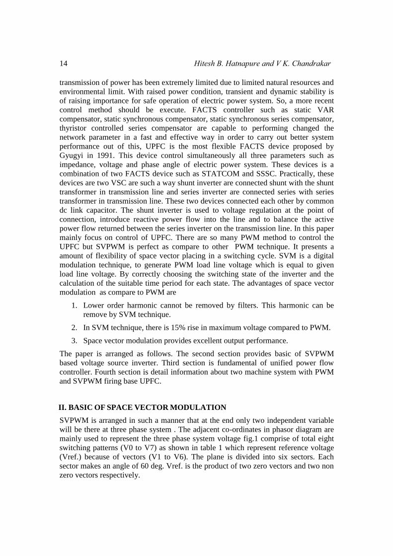
SVPWM is arranged in such a manner that at the end only two independent variable
will be there at three phase system . The adjacent co-ordinates in phasor diagram are
mainly used to represent the three phase system voltage fig.1 comprise of total eight
switching patterns (V0 to V7) as shown in table 1 which represent reference voltage
(Vref.) because of vectors (V1 to V6). The plane is divided into six sectors. Each
sector makes an angle of 60 deg. Vref. is the product of two zero vectors and two non
zero vectors respectively.
Power Quality Improvement By Using SVPWM Based UPFC 15
From the definition of space vector
III
IIII
IVV
VI
sectorV1(100)
V2(110)V3(010)
V4(011)
V5(001)V6(101)
Fig.1. Switching vector of 2-level inverter
V1
V2
Vref
60
60-0
Fig.2. Reference vector
16 Hitesh B. Hatnapure and V K. Chandrakar
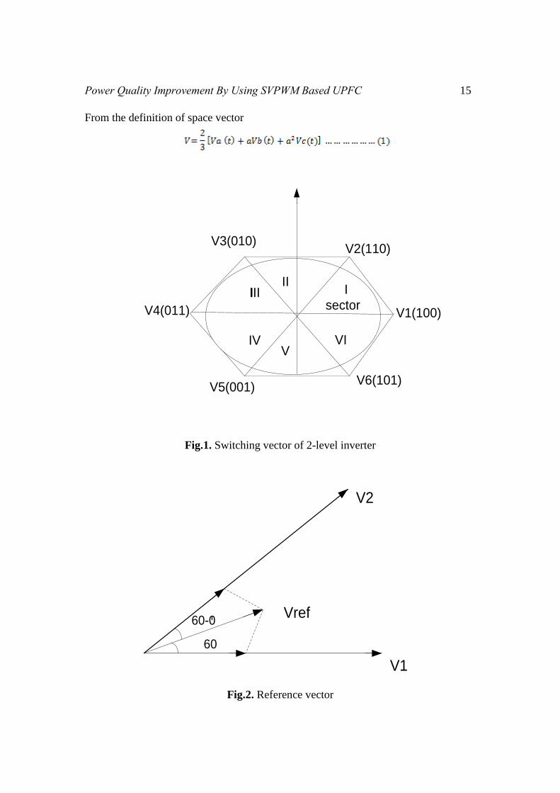
Table.1 : 2-level inverter voltage vector
S. No. Sa Sb Sc Van Vbn Vcn
1 1 0 0 Vdc 0 0
2 1 1 0 Vdc Vdc 0
3 0 1 0 0 Vdc 0
4 0 1 1 0 Vdc Vdc
5 0 0 1 0 0 Vdc
6 1 0 1 Vdc 0 Vdc
7 1 1 1 Vdc Vdc Vdc
8 0 0 0 0 0 0
+Vdc and –Vdc output line voltage are obtained from active state and null state does
not contribute in 2-level inverter to obtain any output line voltage from table 1, “1”
tends to ON state and “0” tends to OFF state of the switches respectively.
By means of three adjacent switching vector reference vector is obtained, likewise
when Vref. drop into sector1 as shown in fig.2, it can be arrange by V1, V2 and V0.
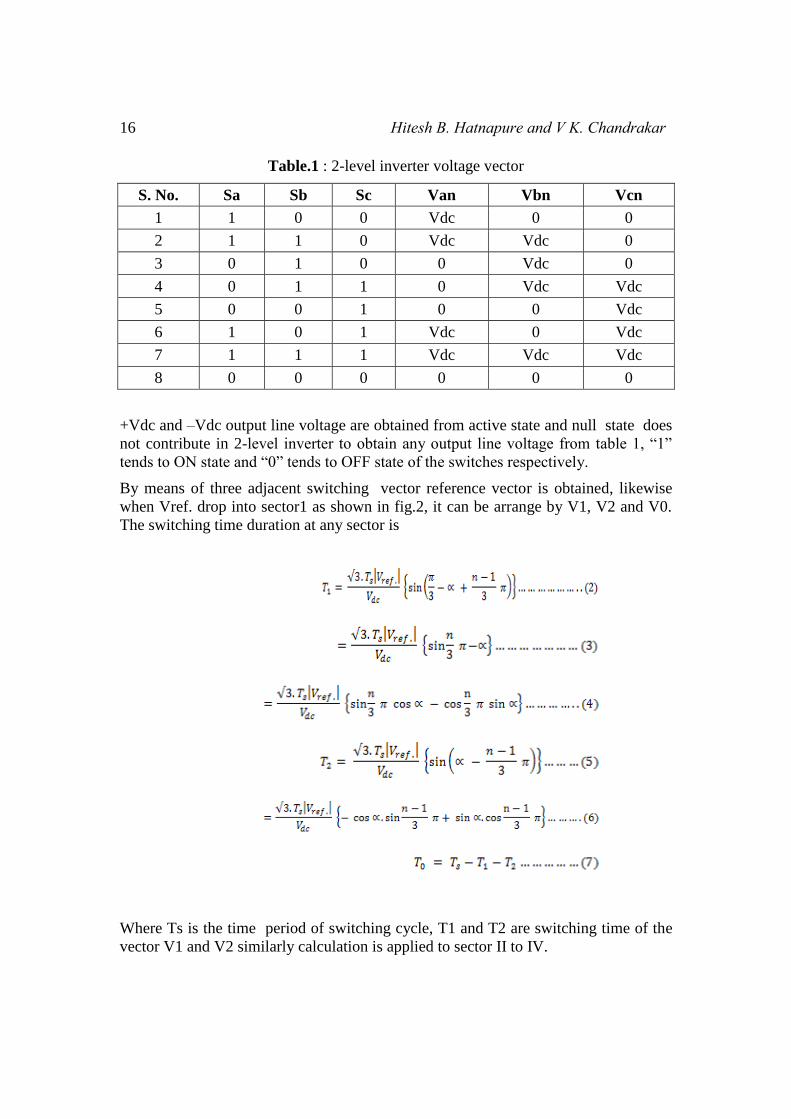
The switching time duration at any sector is
Where Ts is the time period of switching cycle, T1 and T2 are switching time of the
vector V1 and V2 similarly calculation is applied to sector II to IV.
Power Quality Improvement By Using SVPWM Based UPFC 17
The maximum value of Vref. is obtain when
III. UNIFIED POWER FLOW CONTROLLER
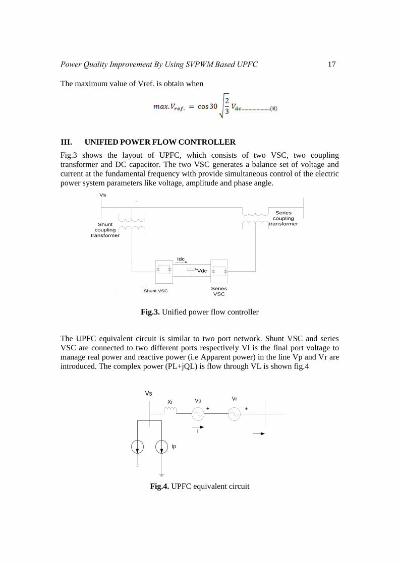
Fig.3 shows the layout of UPFC, which consists of two VSC, two coupling
transformer and DC capacitor. The two VSC generates a balance set of voltage and
current at the fundamental frequency with provide simultaneous control of the electric
power system parameters like voltage, amplitude and phase angle.
Vs
Shunt VSCSeries
VSC
Series
coupling
transformer
Idc
Vdc
Shunt
coupling
transformer
Fig.3. Unified power flow controller
The UPFC equivalent circuit is similar to two port network. Shunt VSC and series
VSC are connected to two different ports respectively Vl is the final port voltage to
manage real power and reactive power (i.e Apparent power) in the line Vp and Vr are
introduced. The complex power (PL+jQL) is flow through VL is shown fig.4
VsVrVpXi
I
Ip
++
Fig.4. UPFC equivalent circuit
18 Hitesh B. Hatnapure and V K. Chandrakar
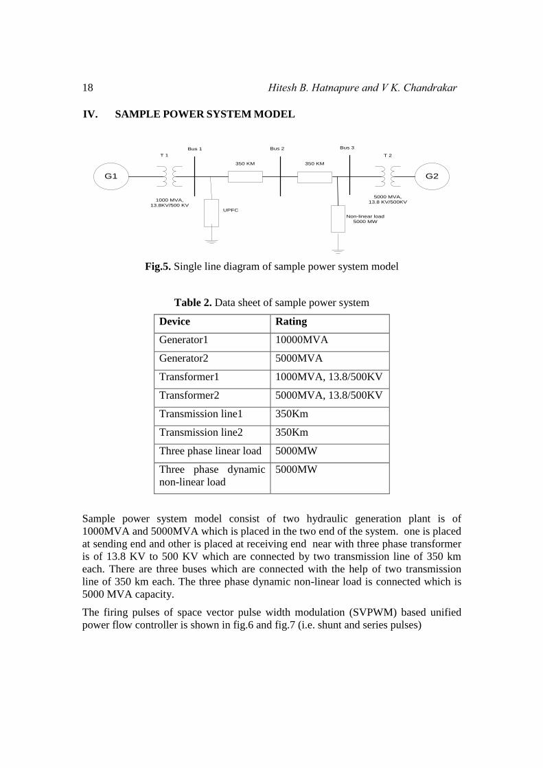
IV. SAMPLE POWER SYSTEM MODEL
G1 G2
5000 MVA,
13.8 KV/500KV
Non-linear load
5000 MW
350 KM350 KM
1000 MVA,
13.8KV/500 KV
Bus 1 Bus 2 Bus 3
UPFC
T 1 T 2
Fig.5. Single line diagram of sample power system model
Table 2. Data sheet of sample power system
Device Rating
Generator1 10000MVA
Generator2 5000MVA
Transformer1 1000MVA, 13.8/500KV
Transformer2 5000MVA, 13.8/500KV
Transmission line1 350Km
Transmission line2 350Km
Three phase linear load 5000MW
Three phase dynamic
non-linear load
5000MW
Sample power system model consist of two hydraulic generation plant is of
1000MVA and 5000MVA which is placed in the two end of the system. one is placed
at sending end and other is placed at receiving end near with three phase transformer
is of 13.8 KV to 500 KV which are connected by two transmission line of 350 km
each. There are three buses which are connected with the help of two transmission
line of 350 km each. The three phase dynamic non-linear load is connected which is
5000 MVA capacity.
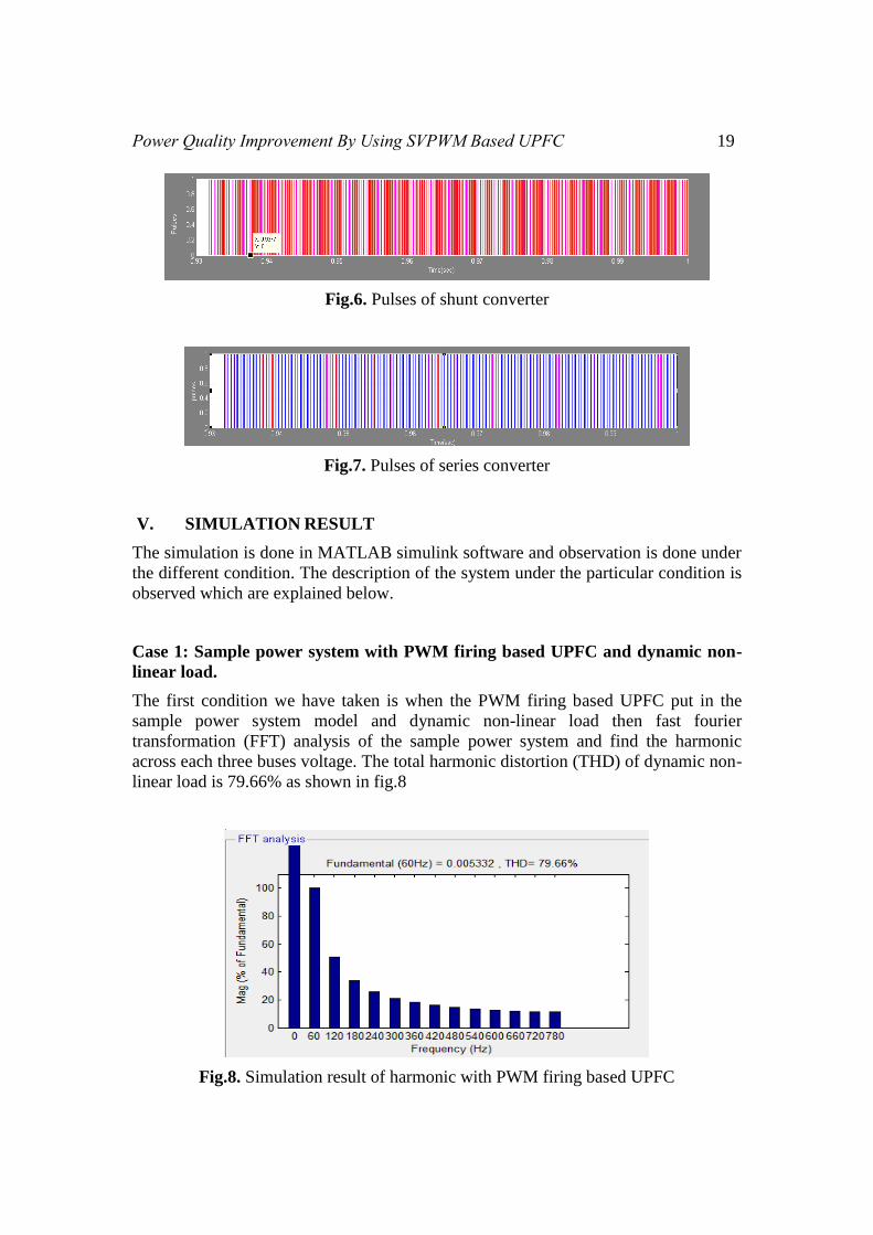
The firing pulses of space vector pulse width modulation (SVPWM) based unified
power flow controller is shown in fig.6 and fig.7 (i.e. shunt and series pulses)
Power Quality Improvement By Using SVPWM Based UPFC 19
Fig.6. Pulses of shunt converter
Fig.7. Pulses of series converter
V. SIMULATION RESULT
The simulation is done in MATLAB simulink software and observation is done under
the different condition. The description of the system under the particular condition is
observed which are explained below.
Case 1: Sample power system with PWM firing based UPFC and dynamic non-
linear load.
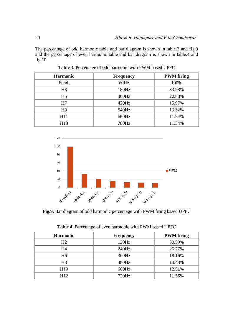
The first condition we have taken is when the PWM firing based UPFC put in the
sample power system model and dynamic non-linear load then fast fourier
transformation (FFT) analysis of the sample power system and find the harmonic
across each three buses voltage. The total harmonic distortion (THD) of dynamic non-
linear load is 79.66% as shown in fig.8
Fig.8. Simulation result of harmonic with PWM firing based UPFC
20 Hitesh B. Hatnapure and V K. Chandrakar
The percentage of odd harmonic table and bar diagram is shown in table.3 and fig.9
and the percentage of even harmonic table and bar diagram is shown in table.4 and
fig.10
Table 3. Percentage of odd harmonic with PWM based UPFC
Harmonic Frequency PWM firing
Fund. 60Hz 100%
H3 180Hz 33.98%
H5 300Hz 20.88%
H7 420Hz 15.97%
H9 540Hz 13.32%
H11 660Hz 11.94%
H13 780Hz 11.34%
Fig.9. Bar diagram of odd harmonic percentage with PWM firing based UPFC
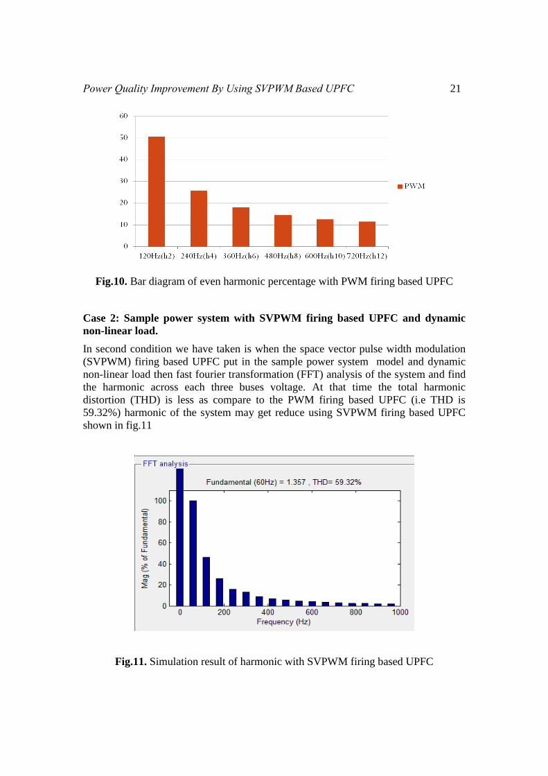
Table 4. Percentage of even harmonic with PWM based UPFC
Harmonic Frequency PWM firing
H2 120Hz 50.59%
H4 240Hz 25.77%
H6 360Hz 18.16%
H8 480Hz 14.43%
H10 600Hz 12.51%
H12 720Hz 11.56%
Power Quality Improvement By Using SVPWM Based UPFC 21
Fig.10. Bar diagram of even harmonic percentage with PWM firing based UPFC
Case 2: Sample power system with SVPWM firing based UPFC and dynamic
non-linear load.
In second condition we have taken is when the space vector pulse width modulation
(SVPWM) firing based UPFC put in the sample power system model and dynamic
non-linear load then fast fourier transformation (FFT) analysis of the system and find
the harmonic across each three buses voltage. At that time the total harmonic
distortion (THD) is less as compare to the PWM firing based UPFC (i.e THD is
59.32%) harmonic of the system may get reduce using SVPWM firing based UPFC
shown in fig.11
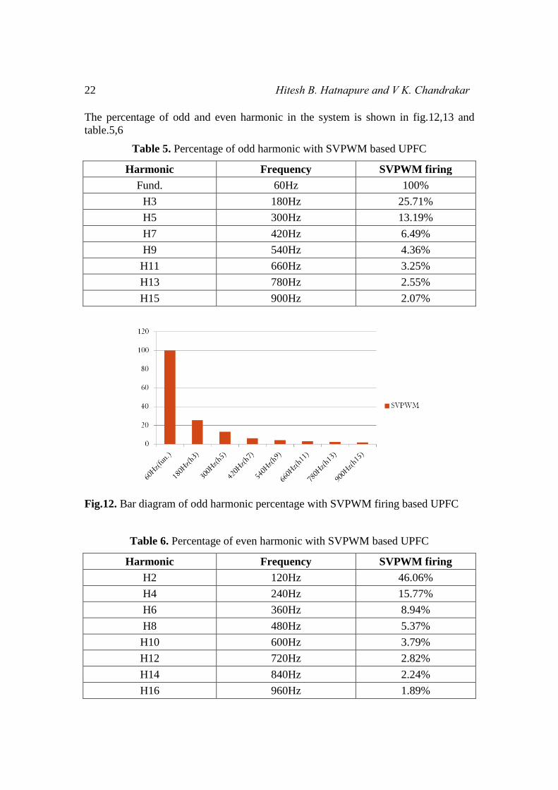
Fig.11. Simulation result of harmonic with SVPWM firing based UPFC
22 Hitesh B. Hatnapure and V K. Chandrakar
The percentage of odd and even harmonic in the system is shown in fig.12,13 and
table.5,6
Table 5. Percentage of odd harmonic with SVPWM based UPFC
Harmonic Frequency SVPWM firing
Fund. 60Hz 100%
H3 180Hz 25.71%
H5 300Hz 13.19%
H7 420Hz 6.49%
H9 540Hz 4.36%
H11 660Hz 3.25%
H13 780Hz 2.55%
H15 900Hz 2.07%
Fig.12. Bar diagram of odd harmonic percentage with SVPWM firing based UPFC
Table 6. Percentage of even harmonic with SVPWM based UPFC
Harmonic Frequency SVPWM firing
H2 120Hz 46.06%
H4 240Hz 15.77%
H6 360Hz 8.94%
H8 480Hz 5.37%
H10 600Hz 3.79%
H12 720Hz 2.82%
H14 840Hz 2.24%
H16 960Hz 1.89%
Power Quality Improvement By Using SVPWM Based UPFC 23
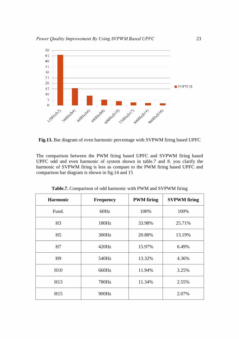
Fig.13. Bar diagram of even harmonic percentage with SVPWM firing based UPFC
The comparison between the PWM firing based UPFC and SVPWM firing based
UPFC odd and even harmonic of system shown in table.7 and 8. you clarify the
harmonic of SVPWM firing is less as compare to the PWM firing based UPFC and
comparison bar diagram is shown in fig.14 and 15
Table.7. Comparison of odd harmonic with PWM and SVPWM firing
Harmonic Frequency PWM firing SVPWM firing
Fund. 60Hz 100% 100%
H3 180Hz 33.98% 25.71%
H5 300Hz 20.88% 13.19%
H7 420Hz 15.97% 6.49%
H9 540Hz 13.32% 4.36%
H10 660Hz 11.94% 3.25%
H13 780Hz 11.34% 2.55%
H15 900Hz 2.07%
24 Hitesh B. Hatnapure and V K. Chandrakar
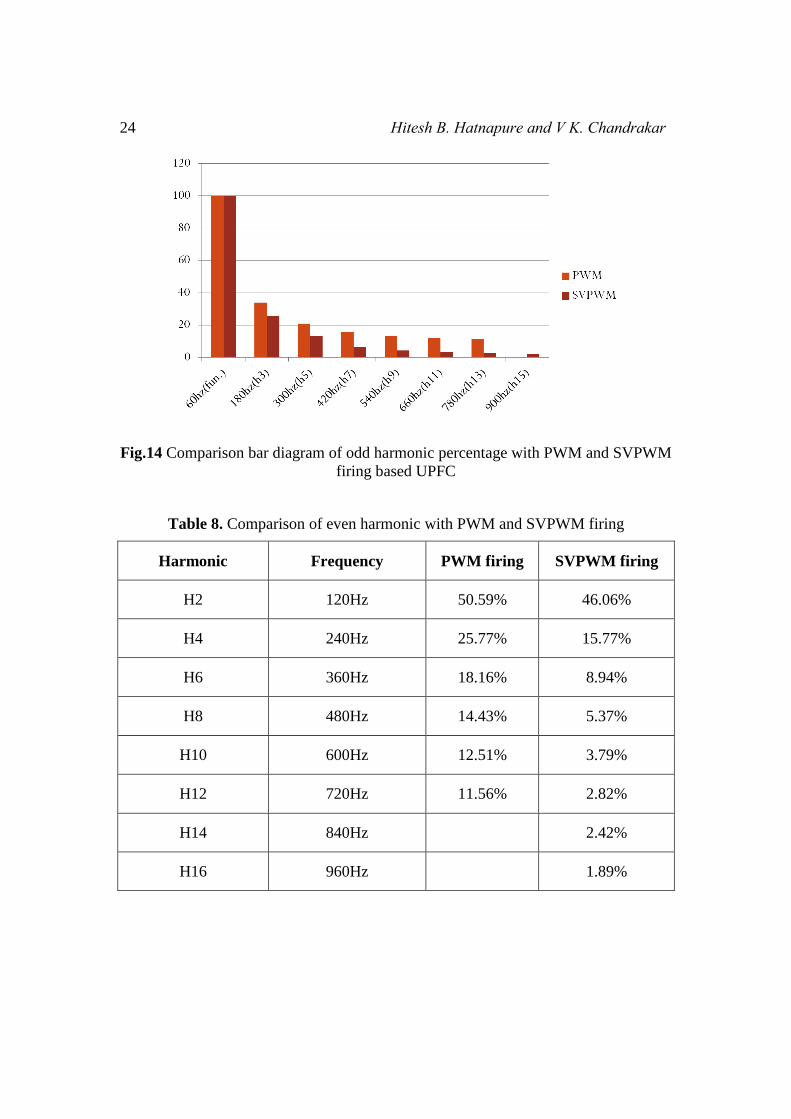
Fig.14 Comparison bar diagram of odd harmonic percentage with PWM and SVPWM
firing based UPFC
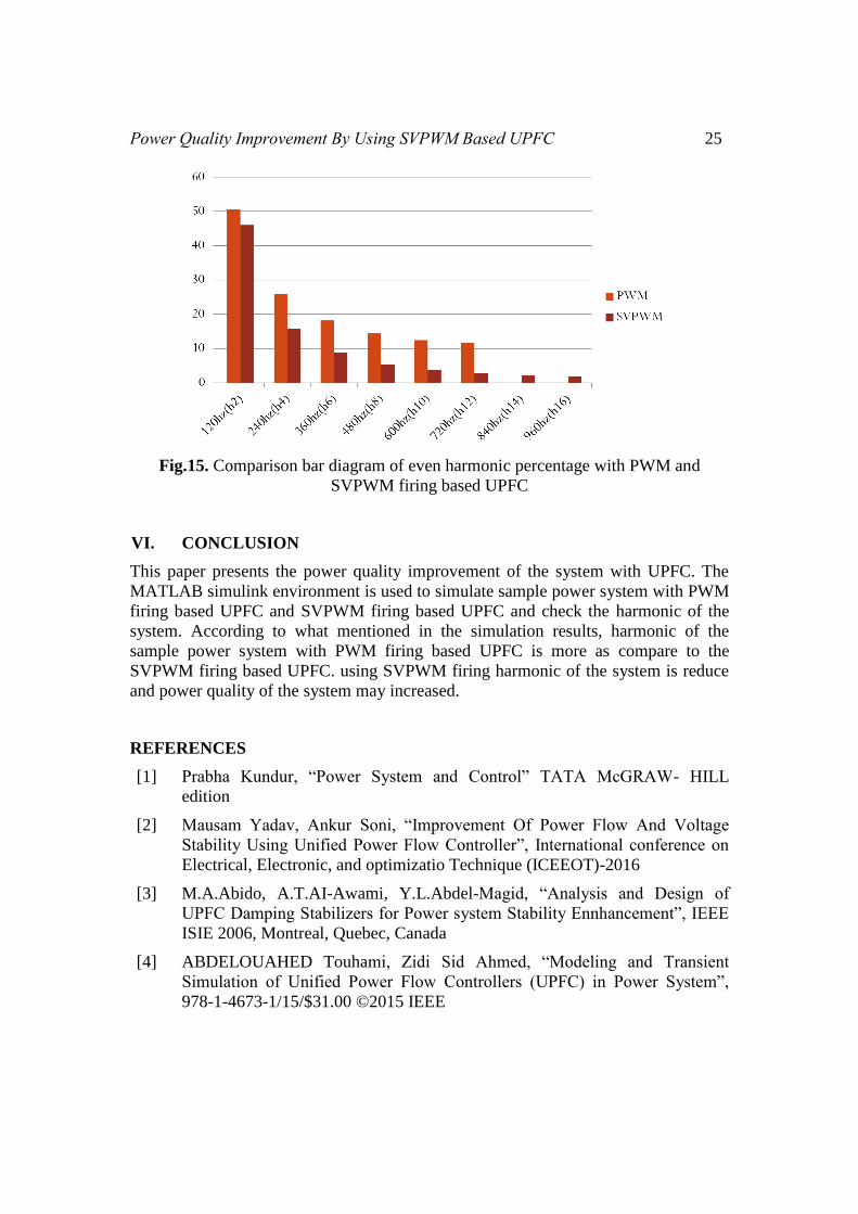
Table 8. Comparison of even harmonic with PWM and SVPWM firing
Harmonic Frequency PWM firing SVPWM firing
H2 120Hz 50.59% 46.06%
H4 240Hz 25.77% 15.77%
H6 360Hz 18.16% 8.94%
H8 480Hz 14.43% 5.37%
H10 600Hz 12.51% 3.79%
H12 720Hz 11.56% 2.82%
H14 840Hz 2.42%
H16 960Hz 1.89%
Power Quality Improvement By Using SVPWM Based UPFC 25
Fig.15. Comparison bar diagram of even harmonic percentage with PWM and
SVPWM firing based UPFC
VI. CONCLUSION
This paper presents the power quality improvement of the system with UPFC. The
MATLAB simulink environment is used to simulate sample power system with PWM
firing based UPFC and SVPWM firing based UPFC and check the harmonic of the
system. According to what mentioned in the simulation results, harmonic of the
sample power system with PWM firing based UPFC is more as compare to the
SVPWM firing based UPFC. using SVPWM firing harmonic of the system is reduce
and power quality of the system may increased.
REFERENCES
[1] Prabha Kundur, “Power System and Control” TATA McGRAW- HILL
edition
[2] Mausam Yadav, Ankur Soni, “Improvement Of Power Flow And Voltage
Stability Using Unified Power Flow Controller”, International conference on
Electrical, Electronic, and optimizatio Technique (ICEEOT)-2016
[3] M.A.Abido, A.T.AI-Awami, Y.L.Abdel-Magid, “Analysis and Design of
UPFC Damping Stabilizers for Power system Stability Ennhancement”, IEEE
ISIE 2006, Montreal, Quebec, Canada
[4] ABDELOUAHED Touhami, Zidi Sid Ahmed, “Modeling and Transient
Simulation of Unified Power Flow Controllers (UPFC) in Power System”,
978-1-4673-1/15/$31.00 ©2015 IEEE
26 Hitesh B. Hatnapure and V K. Chandrakar
[5] Devendra Manikrao Holey, Vinod Kumar Chandrakar, “Dynamic Harmonic
Domain Modelling of Space Vector Based UPFC”, American Journal of
Electrical Power and Energy Systems 2016; 5(1): 1-10
[6] Devendra M. Holey, Vinod Kumar Chandrakar, “Dynamic Harmonic Domain
Modelling of Space Vector Based SSSC”, Energy and Power Engineering,
2016, 8, 152-160
[7] Ravilla Madhusundan, G. Ramamohan Rao, “Modeling and Simulation of a
Distribution STATCOM (D-STATCOM) for Power Quality Problems-Voltage
Sag and Swell Based on Sinusoidal Pulse Width Modulation (SPWM)”,
International Conference on Advances In Engineering, Science and
Management (ICAESM-2012) March 30, 31, 2012 436
[8] Devendra Manikrao Holey, Vinod Kumar Chandrakar, “Harmonic Domain
Modelling of Space Vector Based STATCOM”, Energy and power
Engineering,2016,8,195-203.