Page 1
International Journal of Modern Engineering Research (IJMER)
www.ijmer.com Vol. 2, Issue. 5, Sep.-Oct. 2012 pp-3451-3457 ISSN: 2249-6645
www.ijmer.com 3451 | Page
Veeraiah Kumbha M-Tech Scholar, Power systems,
Department Of Electrical And Electronics Engineering,
JNTU KAKINADA (A.P), India.
N. Sumathi Assistant Professor, M. Tech, (Ph. D) High Voltage
Engineering, Department of Electrical and Electronics
Engineering, JNTU KAKINADA (A.P), India.
Abstract: A Power quality problem is an occurrence
manifested as a nonstandard voltage, current or frequency
that results in a failure or a mis-operation of end user
equipments. Utility distribution networks, sensitive
industrial loads and critical commercial operations suffer
from various types of outages and service interruptions which can cost significant financial losses. With the
restructuring of power systems and with shifting trend
towards distributed and dispersed generation, the issue of
power quality is going to take newer dimensions. Injection
of the wind power into an electric grid affects the power
quality. The performance of the wind turbine and thereby
power quality are determined on the basis of measurements
and the norms followed according to the guideline specified
in International Electro-technical Commission standard,
IEC-61400. The influence of the wind turbine in the grid
system concerning the power quality measurements are-the
active power, reactive power, variation of voltage, flicker, harmonics, and electrical behavior of switching operation
and these are measured according to national/international
guidelines. The paper study demonstrates the power quality
problem due to installation of wind turbine with the grid. In
this proposed scheme STATIC COMPENSATOR
(STATCOM) is connected at a point of common coupling
with a battery energy storage system (BESS) to mitigate the
power quality issues. The battery energy storage is
integrated to sustain the real power source under fluctuating
wind power. The STATCOM control scheme for the grid
connected wind energy generation system for power quality improvement is simulated using MATLAB/SIMULINK in
power system block set. Finally the proposed shceme is
applied for both balanced and unbalanced linear non linear
loads.
Index Terms: International electro-technical commission
(IEC), power quality, wind generating system (WGS).
I. Introduction Electric Power quality is a term which has
captured increasing attention in power engineering in the
recent years. Eventhough this subject has always been of
interest to power engineers,it has assumed considerable
interest in the 1990's. Electric power quality means different
things for different people. To most electric power
engineers, the term refers to a certain sufficiently high grade
of electric service but beyond that there is no universal
agreement. The measure of power quality depends upon the needs of the equipment that is being supplied. What is good
power quality for an electric motor may not be good enough
for a personal computer. Usually the term power quality
refers to maintaining a sinusoidal waveform of bus voltages
at rated voltage and frequency.
The waveform of electric power at generation stage is
purely sinusoidal and free from any distortion. Many of the
Power conversion and consumption equipment are also
designed to function under pure sinusoidal voltage
waveforms. However, there are many devices that distort
the waveform. These distortions may propagate all over the
electrical network. In recent years, there has been an
increased use of non-linear loads which has resulted in an
increased fraction of non-sinusoidal currents and voltages in Electric Network. Classification of power quality areas may
be made according to the source of the problem such as
converters, magnetic circuit non linearity, arc furnace or by
the wave shape of the signal such as harmonics, flicker or
by the frequency spectrum (radio frequency interference).
The wave shape phenomena associated with power quality
may be characterized into synchronous and nonsynchronous
Phenomena. Synchronous phenomena refer to those in
synchronism with A.C waveform at power frequency.
The main aspects of electric power quality
May be categorized as:- a) Fundamental concepts
b) Sources
c) Instrumentation
d) Modeling
e) Analysis
f) Effects
Figure 1 shows some of the typical voltage disturbances.
Figure.1 Typical Voltage Disturbances Voltage disturbance
as shown in above figure
Table-I
Table1 shows the different power quality problems
Custom power Devices like STATCOM (shunt
active power filter), DVR and UPQC (combination of series
and shunt active power filter) are the latest development of
interfacing devices between distribution supply and
Power quality improvement of Distribution lines using
DSTATCOM under various loading conditions
Page 2
International Journal of Modern Engineering Research (IJMER)
www.ijmer.com Vol. 2, Issue. 5, Sep.-Oct. 2012 pp-3451-3457 ISSN: 2249-6645
www.ijmer.com 3452 | Page
consumer appliances to overcome voltage/current
disturbances and improve the power quality by
compensating the reactive and harmonic power generated
or absorbed by the load. wind is the most promising DG sources and their penetration level to the grid is also on
the rise. Although the benefits of DG includes voltage
support, diversification of power sources,
reduction in transmission and distribution losses and
improved reliability.
The solutions of STATCOM is often used in
transmission system. When it is used in distribution system,
it is called D-STATCOM(STATCOM in Distribution
system). D-STATCOM is a key FACTS controller and it
utilizes power electronics to solve many power quality
problems commonly faced by distribution systems.
Potential applications of D-STATCOM include power
factor correction, voltage regulation, load balancing and harmonic reduction. Comparing with the SVC, the D-
STATCOM has quicker response time and compact
structure. It is expected that the D-STATCOM will replace
the roles of SVC in nearly future D-STATCOM and
STATCOM are different in both structure and function,
while the choice of control strategy is related to the main-
circuit structure and main function of compensators [3], so
D-STATCOM and STATCOM adopt different control
strategy. At present, the use of STATCOM is wide and its
strategy is mature, while the introduction of D-STATCOM
is seldom reported. Many control techniques are reported
such as instantaneous reactive power theory (Akagi et al., 1984), power balance theory, etc. In this paper, an indirect
current control technique (Singh et al., 2000a,b) is
employed to obtain gating signals for the Insulated Gate
Bipolar Transistor (IGBT) devices used in current
controlled voltage source inverter (CC-VSI) working as a
DSTATCOM. A model of DSTATCOM is developed using
MATLAB for investigating the transient analysis of
distribution system under balanced/unbalanced linear and
non-linear three-phase and single-phase loads (diode
rectifier with R and R-C load). Simulation results during
steady-state and transient operating conditions of the DSTATCOM are presented and discussed to demonstrate
power factor correction, harmonic elimination and load
balancing capabilities of the DSTATCOM system [5-10].
II. WIND ENERGY SYSTEM A simplified diagram representing some of the common types
of wind energy systems are shown in Fig.2. From the design perspective it is found that some generators are directly
connected to the grid through a dedicated transformer while
others in corporate power electronics. Many designs, however,
include some level of power Electronics to improve
controllability and operating range. Whatever connection
configuration is used, each turbine itself has an effect on the
power quality of the transmission system. Recent analysis and
study shows that the impact of the yaw error and horizontal
wind shear on the power (torque) and voltage oscillations is
more severe than the effects due to the tower shadow and
vertical wind shear.
Fig.2 Different types of wind energy system
The above figure shows different types of wind energy
system
The new grid comes adopted for wind power
integration has identified the problems of integrating large
amounts of wind energy to the electric grid. It suggests that
new wind farms must be able to provide voltage and reactive
power control, frequency control and fault ride-through
capability in order to maintain the electric system stability. For the existing wind farms with variable speed, double-fed
induction generators (DFIG) and synchronous generators
(SG), a frequency response in the turbine control system can
be frequency response in the turbine control system can be
incorporated by a software upgrade. Wind farms with fixed
speed induction generators (FSIG) have to be phased out
because they cannot offer the required voltage or frequency
control. An overview of the developed controllers for the
converter of grid connected system and showed that the DFIG
has now the most efficient design for the regulation of reactive
power and the adjustment of angular velocity to maximize the output power efficiency. These generators can also support the
system during voltage sags. However, the drawbacks of
converter-base systems are harmonic distortions injected into
the system. Being a single-stage buck-boost inverter, with Z-
source inverter can be a good candidate to mitigate the PQ
problems for future DG systems connected to the grid Fig(3).
Fig.3 PMSG-base WECS with dc boost chopper and ZSI
Anti- islanding is one of the important issues for grid
connected DG system. A major challenge for the islanding
operation and control schems is the protection coordination
of distribution systems with bidirectional flows of fault
current. This is unlike the conventional over-current
protection for radial systems with unidirectional flow of fault
current. Therefore extensive research in being carried out and
an overview of the existing protection techniques with
islanding operation and control, for preventing disconnection of DGs during loss of grid, has been discussed.
Page 3
International Journal of Modern Engineering Research (IJMER)
www.ijmer.com Vol. 2, Issue. 5, Sep.-Oct. 2012 pp-3451-3457 ISSN: 2249-6645
www.ijmer.com 3453 | Page
III. MITIGATION OF PQ PROBLEMS There are two ways to mitigate the power quality problems-either form the customer side or from the utility
side. The first approach is called load conditioning, which
ensures that the equipment is less sensitive to power
disturbances, allowing the operation even under
significant voltage distortion. The other solution is to
install line conditioning systems that suppress or
counteracts the power system disturbances. Several
devices including flywheels, super-capacitors, other
energy storage systems, constant voltage transformers,
noise filters, isolations transformers, transient voltage
surge suppressors, harmonic filters are used for the mitigation of specific PQ problems. Custom power
devices(CPD) like DSTATCOM, DVR and UPQC are
capable of mitigating multiple PQ problems associated
with utility distribution and the end used appliance. The
following section of looks at the role of CPDs in
mitigating PQ problems in relation to grid integrated with
wind energy systems.
IV. Distribution Static Compensator (D-
TATCOM)
5.1 System configuration DSTATCOM
DSTATCOM is a shunt-connected custom power device
specially designed for power factor correction, current
harmonics filtering and load balancing. It can also be
used for voltage regulation at a distribution bus. It is often
referred to as a shunt or parallel active power filter. It
consists of a voltage or a current source PWM converter Fig.4.It operates as a current controlled voltage source
and compensates current harmonics by injecting the
harmonic components generated by the load but phase
shifted by 180 degrees. With an appropriate control
scheme, the DSTATCOM can also compensate for poor
load power factor.
Fig.4 system configuration of DSTATCOM
The system configuration of DSTATCOM above shows
figure
When the STATCOM is applied in distribution system is
called DSTACOM (Distribution-STACOM) and its
configuration is the same, or with small modifications,
oriented to a possible future amplification of its possibilities
in the distribution network at low and medium voltage,
implementing the function so that we can describe as flicker damping, harmonic filtering and hole and short interruption
compensation.
Distribution STATCOM (DSTATCOM) exhibits
high speed control of reactive power to provide voltage
stabilization, flicker suppression, and other types of system
control. The DSTATCOM utilizes a design consisting of a
GTO- or IGBT-based voltage sourced converter connected
to the power system via a multi-stage converter transformer.
The DSTATCOM protects the utility transmission or
distribution system from voltage sags and/or flicker caused
by rapidly varying reactive current demand. In utility
applications, a DSTATCOM provides leading or lagging reactive power to achieve system stability during transient
conditions.
The DSTATCOM can also be applied to industrial
facilities to compensate for voltage sag and flicker caused
by non-linear dynamic loads, enabling such problem loads
to co-exist on the same feeder as more sensitive loads. The
DSTATCOM instantaneously exchanges reactive power
with the distribution system without the use of bulky
capacitors or reactors.
Fig.4 Basic circuit diagram of DSTATCOM
The above figure shows basic circuit diagram of distribution
static synchronous compensator.
In most applications, a DSTATCOM can use its
significant short-term transient overload capabilities to reduce the size of the compensation system needed to
handle transient events. The short-term overload capability
is up to 325% for periods of 1 to 3 seconds, which allows
applications such as wind farms and utility voltage
stabilization to optimize the system‟s cost and performance.
The DSTATCOM controls traditional mechanically
switched capacitors to provide optimal compensation on a
both a transient and steady state basis. To prevent the
unbalanced and distorted currents from being drawn from
the distribution bus, a shunt compensator, DSTATCOM,
can be used to ensure that the current drawn from the
distribution bus is balanced and sinusoidal. A Voltage Source Converter (VSC) is used to realize a DSTATCOM.
The structure of the VSC decides the extent of
compensation it can provide.
5.2 Voltage Source Converter (VSC)
A voltage-source converter is a power electronic device that
connected in shunt or parallel to the system. It can generate
a sinusoidal voltage with any required magnitude,
frequency and phase angle. The VSC used to either
completely replace the voltage or to inject the „missing
voltage‟. The „missing voltage‟ is the difference between the nominal voltage and the actual. It also converts the DC
voltage across storage devices into a set of three phase AC
output voltages [8, 9]. In addition, D-STATCOM is also
capable to generate or absorbs reactive power. If the output
voltage of the VSC is greater than AC bus terminal
voltages, D-STATCOM is said to be in capacitive mode.
So, it will compensate the reactive power through AC
system and regulates missing voltages. These voltages are
in phase and coupled with the AC system through the
reactance of coupling transformers. Suitable adjustment of
the phase and magnitude of the DSTATCOM output
voltages allows effectives control of active and reactive
Page 4
International Journal of Modern Engineering Research (IJMER)
www.ijmer.com Vol. 2, Issue. 5, Sep.-Oct. 2012 pp-3451-3457 ISSN: 2249-6645
www.ijmer.com 3454 | Page
power exchanges between D-STATCOM and AC system.
In addition, the converter is normally based on some kind of
energy storage, which will supply the converter with a DC
voltage [10].
5.3 Controller for DSTATCOM
The three-phase reference source currents are computed
using three-phase AC voltages (vta, vtb and vtc) and DC bus
voltage (Vdc) of DSTATCOM. These reference supply
currents consist of two components, one in-phase (Ispdr)
and another in quadrature (Ispqr) with the supply voltages.
The control scheme is represented in Fig. 5. The basic
equations of control algorithm of DSTATCOM are as
follows.
5.3.1 Computation of in-phase components of reference
supply current
The instantaneous values of in-phase component of
reference supply currents (Ispdr) is computed using one PI
controller over the average value of DC bus voltage of the
DSTATCOM (vdc) and reference DC voltage (vdcr) as
𝐼𝑠𝑝𝑑𝑟 = 𝐼𝑠𝑝𝑑𝑟 𝑛−1 + 𝐾𝑝𝑑 𝑉𝑑𝑒 𝑛 − 𝑉𝑑𝑒 𝑛−1 + 𝐾𝑖𝑑𝑉𝑑𝑒 𝑛
where Vde(n) Vdcc-Vdcn) denotes the error in Vdcc and
average value of Vdc Kpd and Kid are proportional and
integral gains of the DC bus voltage PI controller. The
output of this PI controller (Ispdr) is taken as amplitude of
in-phase component of the reference supply currents. Three-phase in-phase components of the reference supply currents
(isadr, isbdr and iscdr) are computed using the in-phase unit
current vectors (ua, ub and uc) derived from the AC
terminal voltages (vtan, vtbn and vtcn), respectively.
𝑈𝑎 = 𝑉𝑡𝑎 𝑉𝑡𝑚 𝑈𝑏 = 𝑉𝑡𝑏 𝑉𝑡𝑚 𝑈𝑐 = 𝑉𝑡𝑐 𝑉𝑡𝑚 where Vtm is amplitude of the supply voltage and it is
computed as
𝑉𝑡𝑚 = 23 𝑉𝑡𝑎𝑛
2 + 𝑉𝑡𝑏𝑛2 + 𝑉𝑡𝑐𝑛
2
The instantaneous values of in-phase component of
reference supply currents (isadr, isbdr and iscdr) are
computed as
𝐼𝑠𝑎𝑑𝑟 = 𝐼𝑠𝑝𝑑𝑠 𝑈𝑎 𝐼𝑠𝑏𝑑𝑟 = 𝐼𝑠𝑝𝑑𝑟 𝑈𝑏 𝐼𝑠𝑐𝑑𝑟 = 𝐼𝑠𝑝𝑑𝑟 𝑈𝑐
5.3.2 Computation of quadrature components of reference
supply current
The amplitude of quadrature component of reference supply
currents is computed using a second PI controller over the
amplitude of supply voltage (vtm) and its reference value
(vtmr)
𝐼𝑠𝑝𝑞𝑟 (𝑛) = 𝐼𝑠𝑝𝑞𝑟 (𝑛−1) + 𝐾𝑝𝑞 {𝑉𝑎𝑐 (𝑛) − 𝑉𝑎𝑐 (𝑛−1)} + 𝐾𝑖𝑞𝑉𝑎𝑐 (𝑛)
Where Vac = VtmcVmc(n) denotes the error in Vtmc and
computed value Vtmn from Equation (3) and Kpq and Kiq
are the proportional and integral gains of the second PI
controller.
𝑊𝑎 = −𝑈𝑏 + 𝑈𝐶 3
𝑊𝑏 = 𝑈𝑎 3 + 𝑈𝑏 − 𝑈𝑐 2 3
𝑊𝑐 = −𝑈𝑎 3 + 𝑈𝑏 − 𝑈𝑐 2 3
Three-phase quadrature components of the reference supply currents (isaqr, isbqr and iscqr) are computed using the
output of second PI controller (Ispqr) and quadrature unit
current vectors (wa, wb and wc ) as
𝑖𝑠𝑎𝑞𝑟 = 𝐼𝑠𝑝𝑞𝑟 𝑊𝑎 , 𝑖𝑠𝑏𝑞𝑟 = 𝐼𝑠𝑝𝑞𝑟 𝑊𝑏 , 𝑖𝑠𝑐𝑞𝑟 = 𝐼𝑠𝑝𝑞𝑟 𝑊𝑐 ,
5.3.3 Computation of total reference supply currents
Three-phase instantaneous reference supply currents (isar, isbr and iscr) are computed by adding in-phase (isadr, isbdr
and iscdr) and quadrature components of supply currents
(isaqr, isbqr and iscqr) as
𝑖𝑠𝑎𝑟 = 𝑖𝑠𝑎𝑑𝑟 + 𝑖𝑠𝑎𝑞𝑟 , 𝑖𝑠𝑏𝑟 = 𝑖𝑠𝑏𝑑𝑟 + 𝑖𝑠𝑏𝑞𝑟 ,
𝑖𝑠𝑐𝑟 = 𝑖𝑠𝑐𝑑𝑟 + 𝑖𝑠𝑐𝑞𝑟
A hysteresis pulse width modulated (PWM) current
controller is employed over the reference (isar, isbr and
iscr) and sensed supply currents (isa, isb and isc) to generate
gating pulses for IGBTs of DSTATCOM.
Figure. 5 Control methods for DTSATCOM
Page 5
International Journal of Modern Engineering Research (IJMER)
www.ijmer.com Vol. 2, Issue. 5, Sep.-Oct. 2012 pp-3451-3457 ISSN: 2249-6645
www.ijmer.com 3455 | Page
V. MATAB/SIMULINK MODELING OF DSTATCOM
6.1 Modeling of Power Circuit
Fig. 6 shows the complete MATLAB model of
DSTATCOM along with control circuit. The power circuit
as well as control system are modelled using Power System Blockset and Simulink. The grid source is represented by
three-phase AC source. Three-phase AC loads are
connected at the load end. DSTATCOM is connected in
shunt and it consists of PWM voltage source inverter circuit
and a DC capacitor connected at its DC bus. An IGBT-
based PWM inverter is implemented using Universal bridge
block from Power Electronics subset of PSB. Snubber
circuits are connected in parallel with each IGBT for
protection. Simulation of DSTATCOM system is carried
out for linear and non-linear loads. The linear load on the
system is modelled using the block three-phase parallel R-L
load connected in delta configuration. The non-linear load on the system is modelled using R and R-C circuits
connected at output of the diode rectifier. Provision is made
to connect loads in parallel so that the effect of sudden load
addition and removal is studied. The feeder connected from
the three-phase source to load is modelled using appropriate
values of resistive and inductive components.
5.1 Modeling of Control Circuit
Fig. 7 shows the control algorithm of DSTATCOM with
two PI controllers. One PI controller regulates the DC link
voltage while the second PI controller regulates the terminal voltage at PCC. The in-phase components of DSTATCOM
reference currents are responsible for power factor
correction of load and the quadrature components of supply
reference currents are to regulate the AC system voltage at
PCC.
The output of PI controller over the DC bus voltage (Ispdr)
is considered as the amplitude of the in-phase component of
supply reference currents and the output of PI controller
over AC terminal voltage (Ispqr) is considered as the
amplitude of the quadrature component of supply reference
currents. The instantaneous reference currents (isar, isbr and
iscr) are obtained by adding the in-phase supply reference currents (isadr, isbdr and iscdr) and quadrature supply
reference currents (isaqr, isbqr and iscqr). Once the
reference supply currents are generated, a carrierless
hysteresis PWM controller is employed over the sensed
supply currents (isa, isb and isc) and instantaneous
reference currents (isar, isbr and iscr) to generate gating
pulses to the IGBTs of DSTATCOM. The controller
controls the DSTATCOM currents to maintain supply
currents in a band around the desired reference current
values. The hysteresis controller generates appropriate
switching pulses for six IGBTs of the VSI working as
DSTATCOM.
VI. SIMULATION RESULTS Here Simulation results are presented for four cases. In case
one load is balanced non linear, case two load is
unbalanced non linear, case three load is balanced linear
and in case four unbalanced linear load is considered.
6.1 Case one
Performance of DSTATCOM connected to a weak supply system is shown in Fig.5 for power factor correction and
load balancing. This figure shows variation of performance
variables such as supply voltages (vsa, vsb and vsc),
terminal voltages at PCC (vta, vtb and vtc), supply currents
(isa, isb and isc), load currents (ila, ilb and ilc),
DSTATCOM currents (ica, icb and icc) and DC link
voltage (Vdc).
Figure. 6 Matlab/Simulink Model of DSTATCOM
Power Circuit
Figure. 7 Control Circuit
Page 6
International Journal of Modern Engineering Research (IJMER)
www.ijmer.com Vol. 2, Issue. 5, Sep.-Oct. 2012 pp-3451-3457 ISSN: 2249-6645
www.ijmer.com 3456 | Page
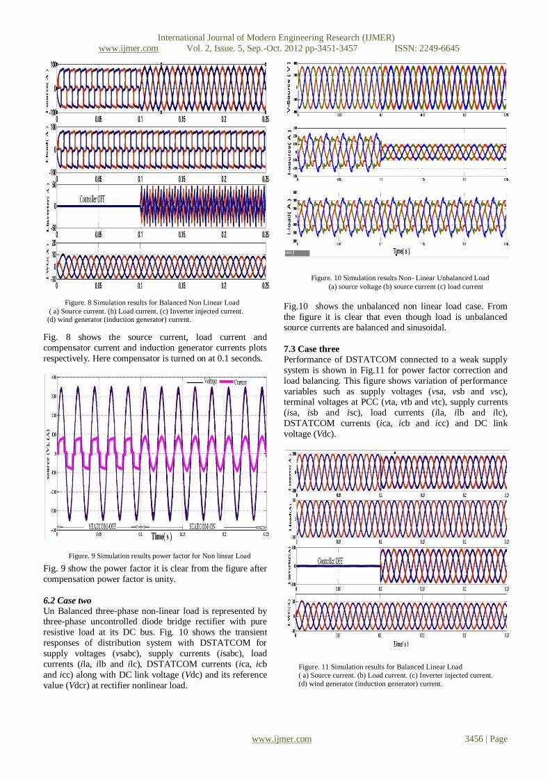
Fig. 8 shows the source current, load current and
compensator current and induction generator currents plots
respectively. Here compensator is turned on at 0.1 seconds.
Fig. 9 show the power factor it is clear from the figure after
compensation power factor is unity.
6.2 Case two
Un Balanced three-phase non-linear load is represented by three-phase uncontrolled diode bridge rectifier with pure
resistive load at its DC bus. Fig. 10 shows the transient
responses of distribution system with DSTATCOM for
supply voltages (vsabc), supply currents (isabc), load
currents (ila, ilb and ilc), DSTATCOM currents (ica, icb
and icc) along with DC link voltage (Vdc) and its reference
value (Vdcr) at rectifier nonlinear load.
Fig.10 shows the unbalanced non linear load case. From
the figure it is clear that even though load is unbalanced
source currents are balanced and sinusoidal.
7.3 Case three
Performance of DSTATCOM connected to a weak supply
system is shown in Fig.11 for power factor correction and
load balancing. This figure shows variation of performance
variables such as supply voltages (vsa, vsb and vsc), terminal voltages at PCC (vta, vtb and vtc), supply currents
(isa, isb and isc), load currents (ila, ilb and ilc),
DSTATCOM currents (ica, icb and icc) and DC link
voltage (Vdc).
Figure. 8 Simulation results for Balanced Non Linear Load
( a) Source current. (b) Load current. (c) Inverter injected current. (d) wind generator (induction generator) current.
Figure. 9 Simulation results power factor for Non linear Load
Figure. 10 Simulation results Non- Linear Unbalanced Load
(a) source voltage (b) source current (c) load current
Figure. 11 Simulation results for Balanced Linear Load
( a) Source current. (b) Load current. (c) Inverter injected current.
(d) wind generator (induction generator) current.
Page 7
International Journal of Modern Engineering Research (IJMER)
www.ijmer.com Vol. 2, Issue. 5, Sep.-Oct. 2012 pp-3451-3457 ISSN: 2249-6645
www.ijmer.com 3457 | Page
Fig. 12 shows the power factor it is clear from the figure
after compensation power factor is unity.
7.4 Case four
Un Balanced three-phase linear load is represented by three-phase uncontrolled diode bridge rectifier with pure resistive
load at its DC bus. Fig. 10 shows the transient responses of
distribution system with DSTATCOM for supply voltages
(vsabc), supply currents (isabc), load currents (ila, ilb and
ilc), inverter current (Iina, Iinb, Iinc) DSTATCOM currents
(ica, icb and icc) along with DC link voltage (Vdc) and its
reference value (Vdcr) at rectifier linear load.
VII. Conclusion DSTATCOM system is an efficient mean for mitigation of PQ disturbances introduced to the grid by DERs.
DSTATCOM compensator is a flexible device which can
operate in current control mode for compensating voltage
variation, unbalance and reactive power and in voltage
control mode as a voltage stabilizer. The latter feature
enables its application for compensation of dips coming
from the supplying network. The simulation results show
that the performance of DSTATCOM system has been
found to be satisfactory for improving the power quality at
the consumer premises. DSTATCOM control algorithm is
flexible and it has been observed to be capable of correcting power factor to unity, eliminate harmonics in supply
currents and provide load balancing. It is also able to
regulate voltage at PCC. The control algorithm of
DSTATCOM has an inherent property to provide a self-
supporting DC bus of DSTATCOM. It has been found that
the DSTATCOM system reduces THD in the supply
currents for non-linear loads. Rectifier-based non-linear
loads generated harmonics are eliminated by DSTATCOM.
When single-phase rectifier loads are connected,
DSTATCOM currents balance these unbalanced load
currents.
References [1] A.E. Hammad, Comparing the Voltage source
capability of Present and future Var Compensation
Techniques in Transmission System, IEEE Trans, on
Power Delivery . volume 1. No.1 Jan 1995.
[2] G.Yalienkaya, M.H.J Bollen, P.A. Crossley,
“Characterization of Voltage Sags in Industrial
Distribution System”, IEEE transactions on industry
applications, volume 34, No. 4, July/August, PP.682-688, 1999.
[3] Haque, M.H., “Compensation Of Distribution
Systems Voltage sags by DVR and D-STATCOM”,
Power Tech Proceedings, 2001 IEEE Porto, Volume
1, PP.10-13, September 2001.
[4] Anaya-Lara O, Acha E., “Modeling and Analysis Of
Custom Power Systems by PSCAD/EMTDC”, IEEE
Transactions on Power Delivery, Volume 17, Issue:
2002, Pages: 266-272.
[5] Bollen, M.H.J.,”Voltage sags in Three Phase
Systems”, Power Engineering Review, IEEE, Volume 21, Issue :9, September 2001, PP: 11-15.
[6] M.Madrigal, E.Acha., “Modelling OF Custom Power
Equipment Using Harmonics Domain
Techniques”,IEEE 2000.
[7] R.Meinski, R.Pawelek and I.Wasiak, “Shunt
Compensation For Power Quality Improvement
Using a STATCOM controller Modelling and
Simulation”, IEEE Proce, Volume 151, No. 2, March
2004.
[8] J.Nastran , R. Cajhen, M. Seliger, and
P.Jereb,”Active Power Filters for Nonlinear AC
loads, IEEE Trans.on Power Electronics Volume 9, No.1, PP: 92-96, Jan 2004.
[9] L.A.Moran, J.W. Dixon , and R.Wallace, A Three
Phase Active Power Filter with fixed Switching
Frequency For Reactive Power and Current
Harmonics Compensation, IEEE Trans. On Industrial
Electronics. Volume 42, PP:402-8, August 1995.
[10] L.T. Moran ,P.D Ziogas, and G.Joos , Analysis and
Design Of Three Phase Current source solid State
Var Compensator, IEEE Trans, on Indutry
Applications. Volume 25, No.2, 1989, PP:356-65.
Figure. 12 Simulation results power factor for linear Load
Figure. 13 Simulation results for unbalanced linear Load


![REVIEW OF CONTROL STRATEGIES OF DSTATCOM · Fig. 2 Equivalent circuit of DSTATCOM The operation of DSTATCOM is explained in the following modes [2]: Mode 1: If V SHabc is in-phase](https://static.documents.pub/doc/80x56/5ec37ced6f2e09596744a3b6/review-of-control-strategies-of-dstatcom-fig-2-equivalent-circuit-of-dstatcom-the.jpg)


