• Describing a Power Quality Waveform • Sample PQ Monitoring Videos• Sample PQ Waveforms
• Monitoring Equipment • PQ Definitions • Power Quality Issues and Expected Waveforms
• Voltage Variations• Transients• Harmonics• Wiring and Grounding Considerations
• Power Quality Lab Overview• Final Exam
3
Outline• Introduction
• Describing a Power Quality Waveform • Sample PQ Monitoring Videos• Sample PQ Waveforms
• Monitoring Equipment • PQ Definitions • Power Quality Issues and Expected Waveforms
• Voltage Variations• Transients• Harmonics• Wiring and Grounding Considerations
• Power Quality Lab Overview• Final Exam
4
Waveform Analysis – What’s Important?• Waveshape• Number of Phases Affected• Voltage or Current?• Monitoring Location • Primary/Secondary (CT/PT)• Monitoring Equipment (Capabilities)• Who Captured the Measurements?• Setup (Trigger on Event Type)• Duration of Event• Repetition/Time Between Events• Definition of Good/Bad
5
Videos of Measurements• Phase Shifting• Active Filter• 18 Pulse Drive
6
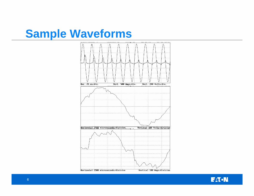
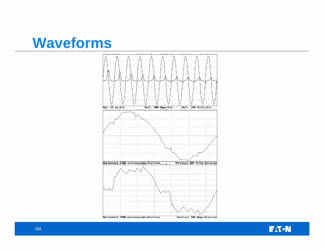
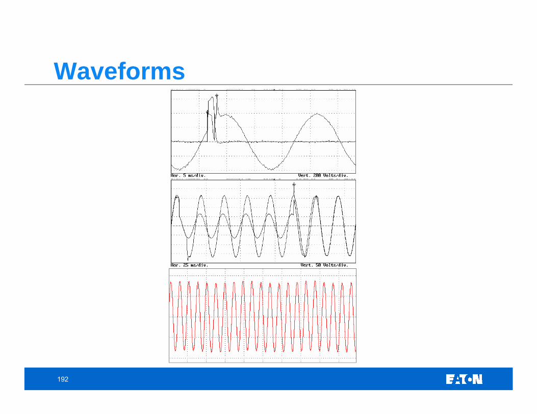
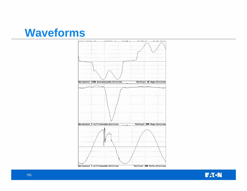
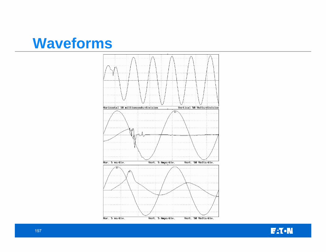
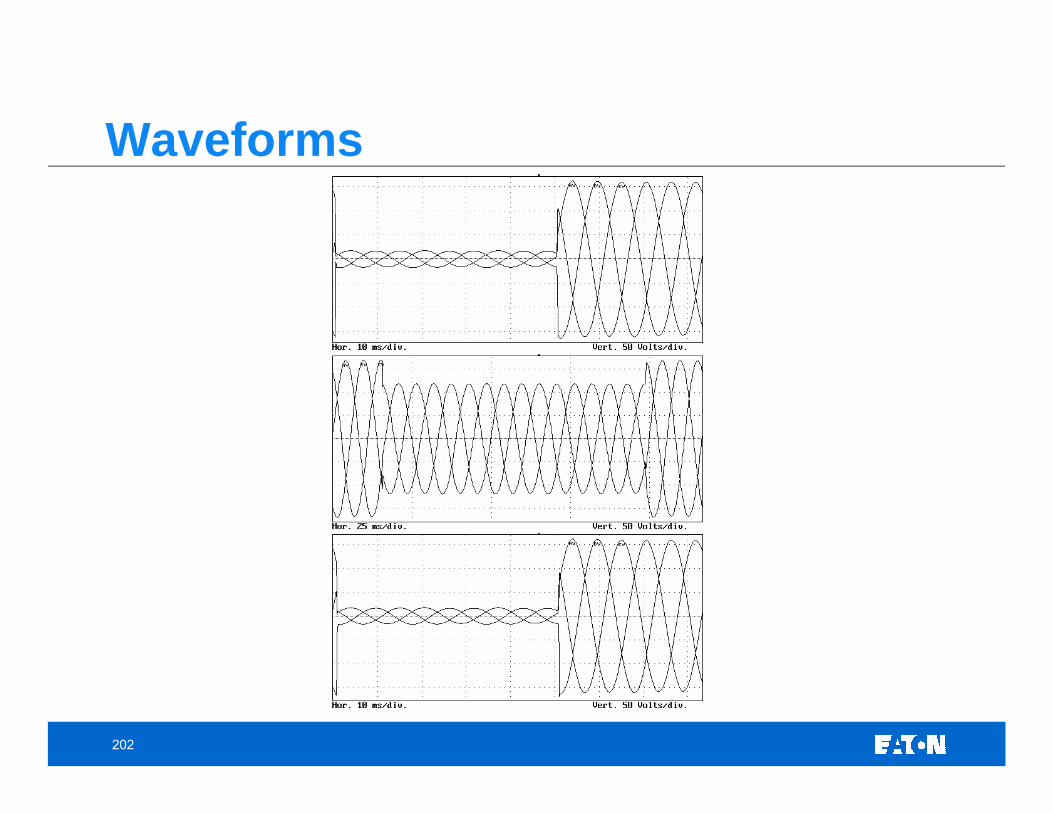
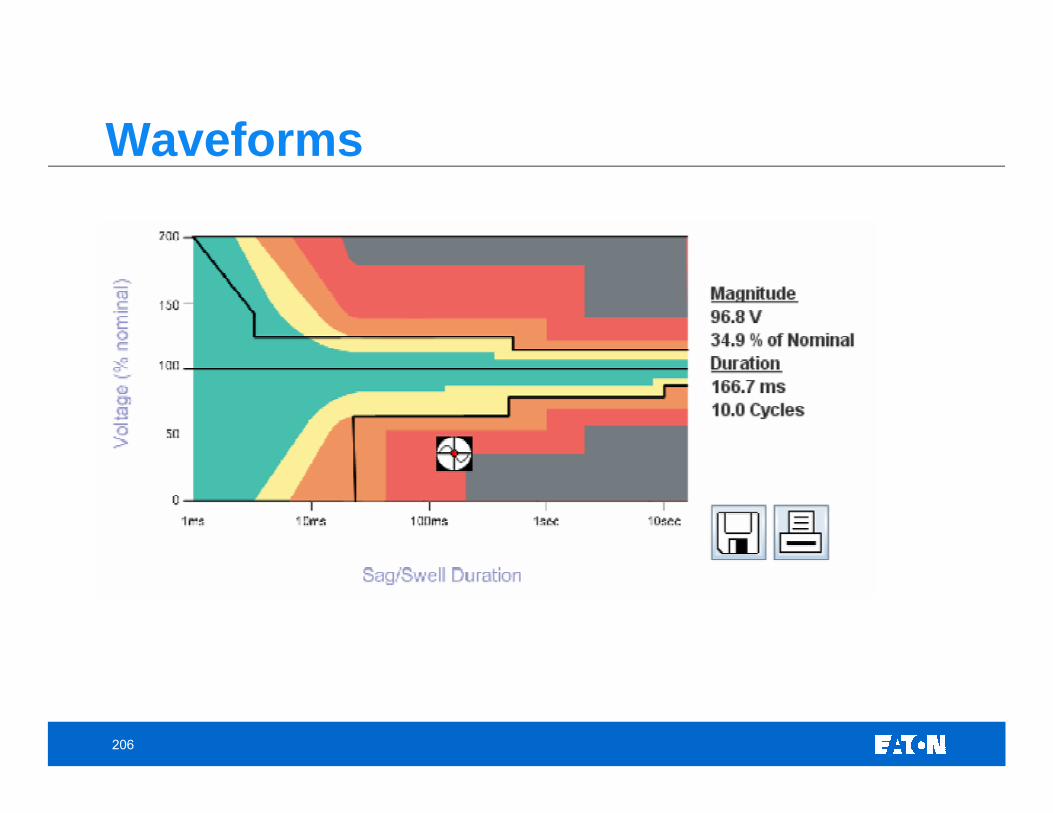
Sample Waveforms
7
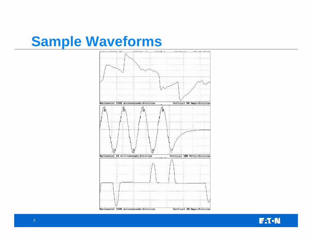
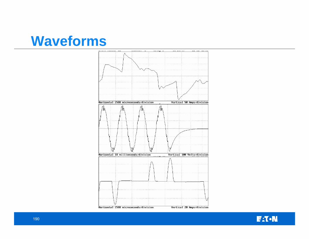
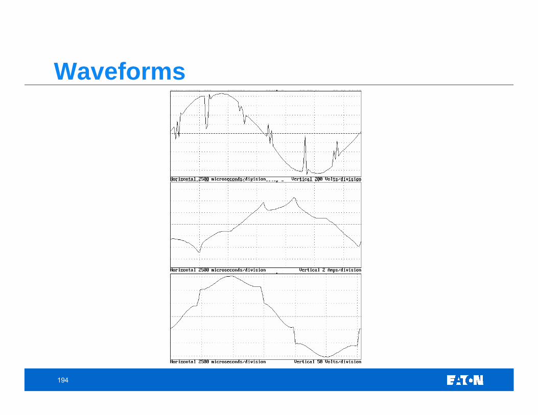
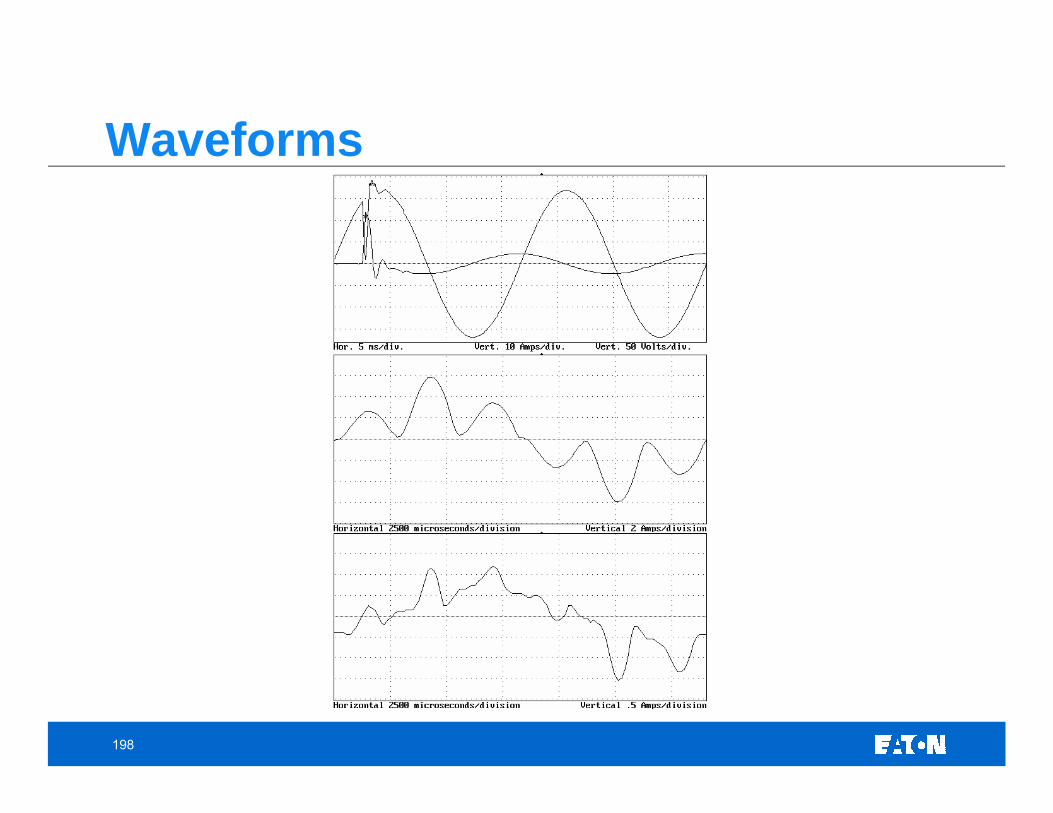
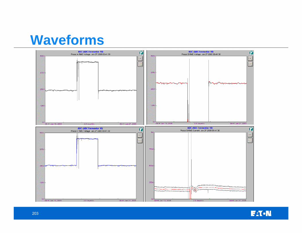
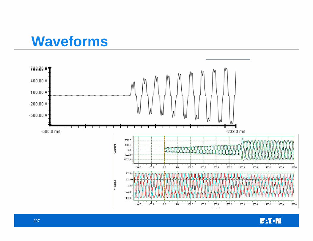
Sample Waveforms
8
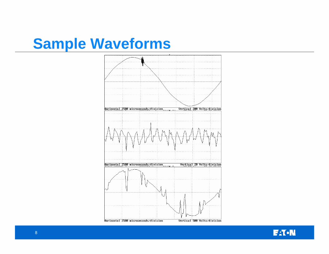
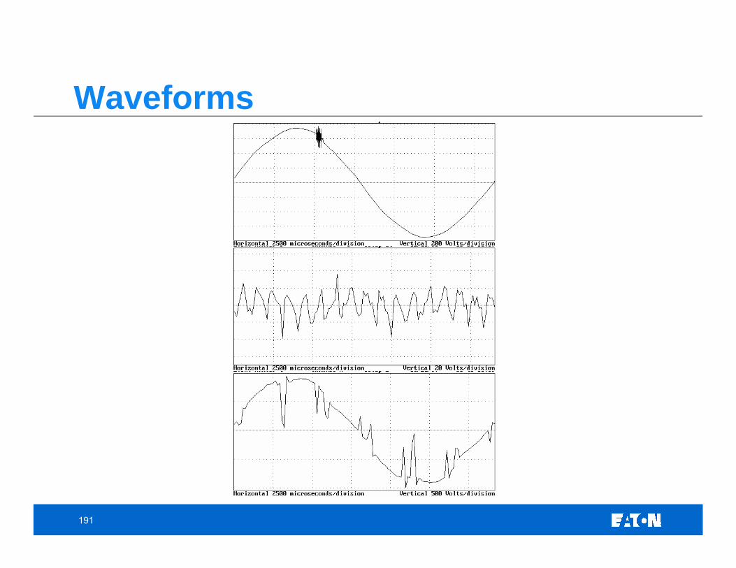
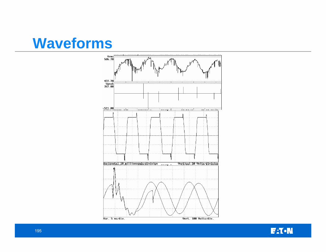
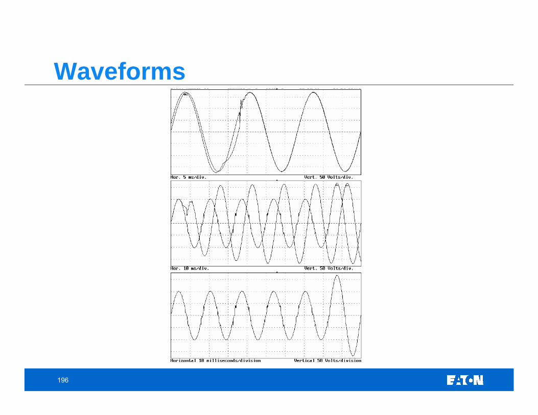
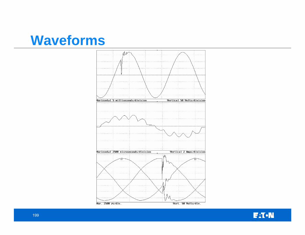
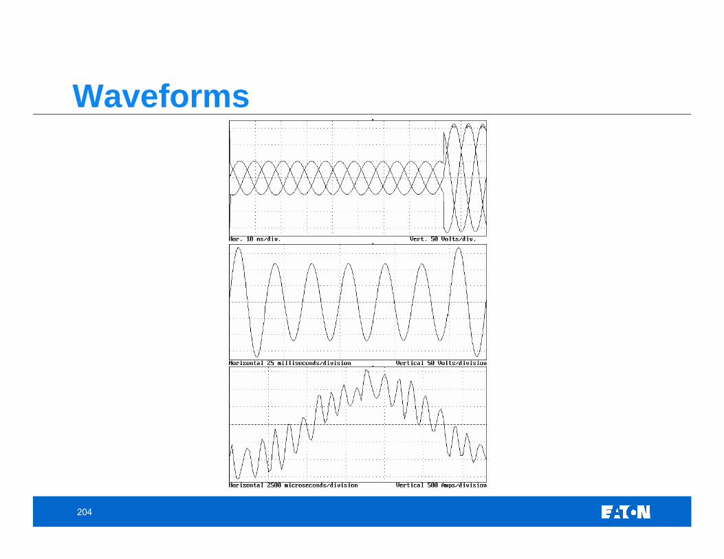
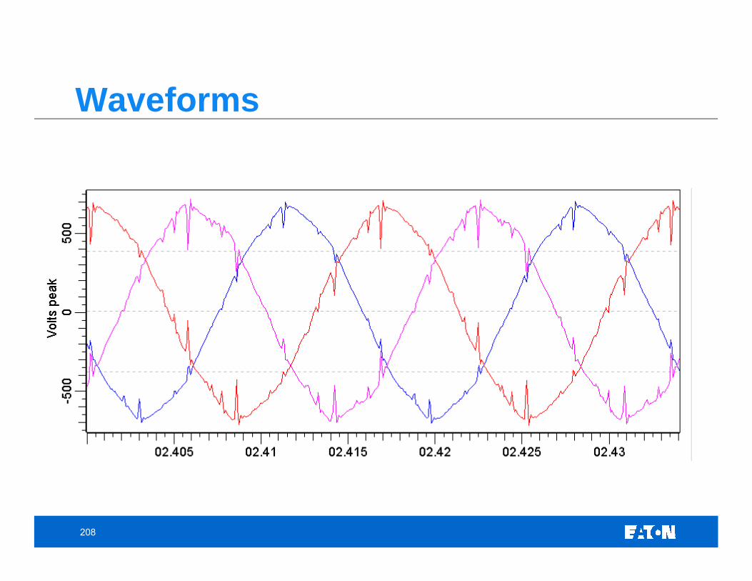
Sample Waveforms
9
Outline• Introduction
• Describing a Power Quality Waveform • Sample PQ Monitoring Videos• Sample PQ Waveforms
• Monitoring Equipment• PQ Definitions • Power Quality Issues and Expected Waveforms
• Voltage Variations• Transients• Harmonics• Wiring and Grounding Considerations
• Power Quality Lab Overview• Final Exam
10
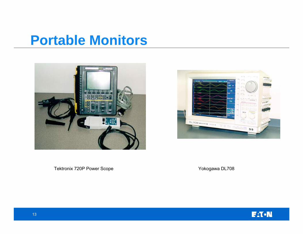
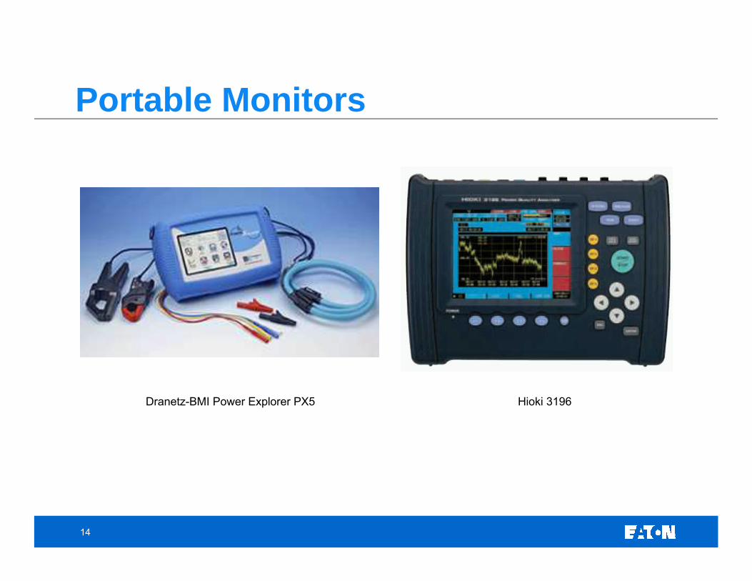
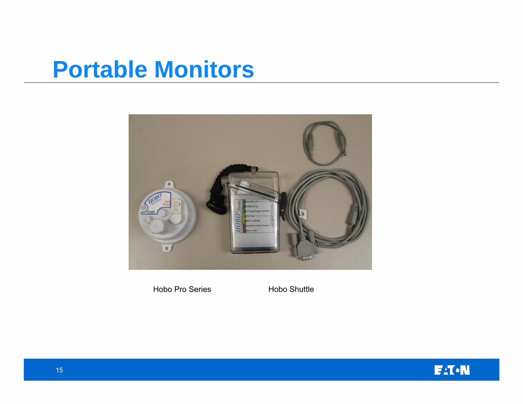
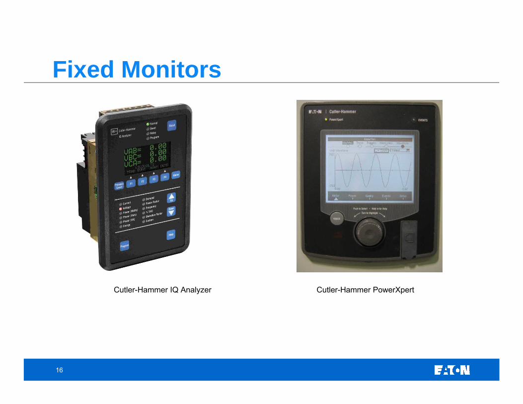
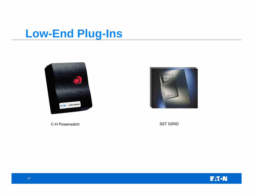
PQ Monitors- Portable- Permanent/Fixed
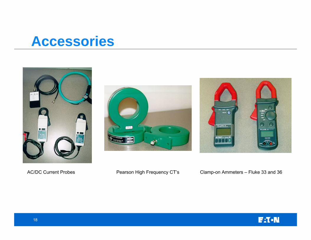
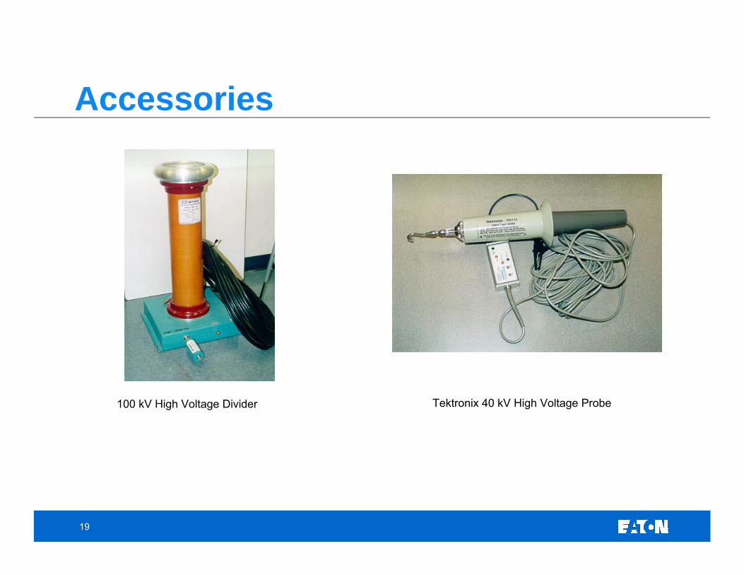
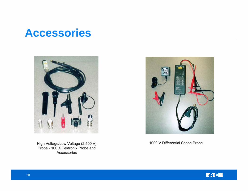
Accessories- Current Transformers- Voltage Probes- High Voltage Dividers- Special Connectors and Cables- Compensated Cables- Battery Backup- Disk Storage
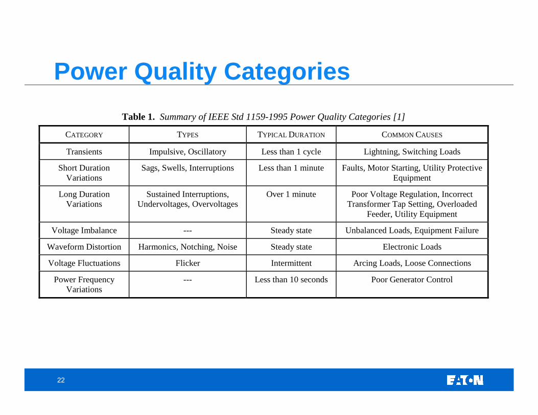
Over 1 minute Poor Voltage Regulation, Incorrect Transformer Tap Setting, Overloaded
Feeder, Utility Equipment
Voltage Imbalance --- Steady state Unbalanced Loads, Equipment Failure
Waveform Distortion Harmonics, Notching, Noise Steady state Electronic Loads
Voltage Fluctuations Flicker Intermittent Arcing Loads, Loose Connections
Power Frequency Variations
--- Less than 10 seconds Poor Generator Control
23
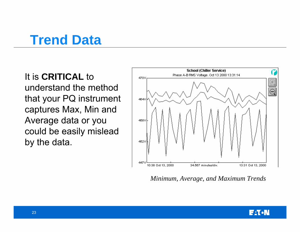
Trend Data
Minimum, Average, and Maximum Trends
It is CRITICAL to understand the method that your PQ instrument captures Max, Min and Average data or you could be easily mislead by the data.
24
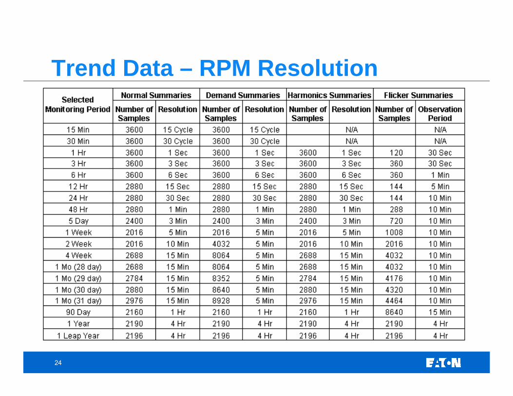
Trend Data – RPM Resolution
25
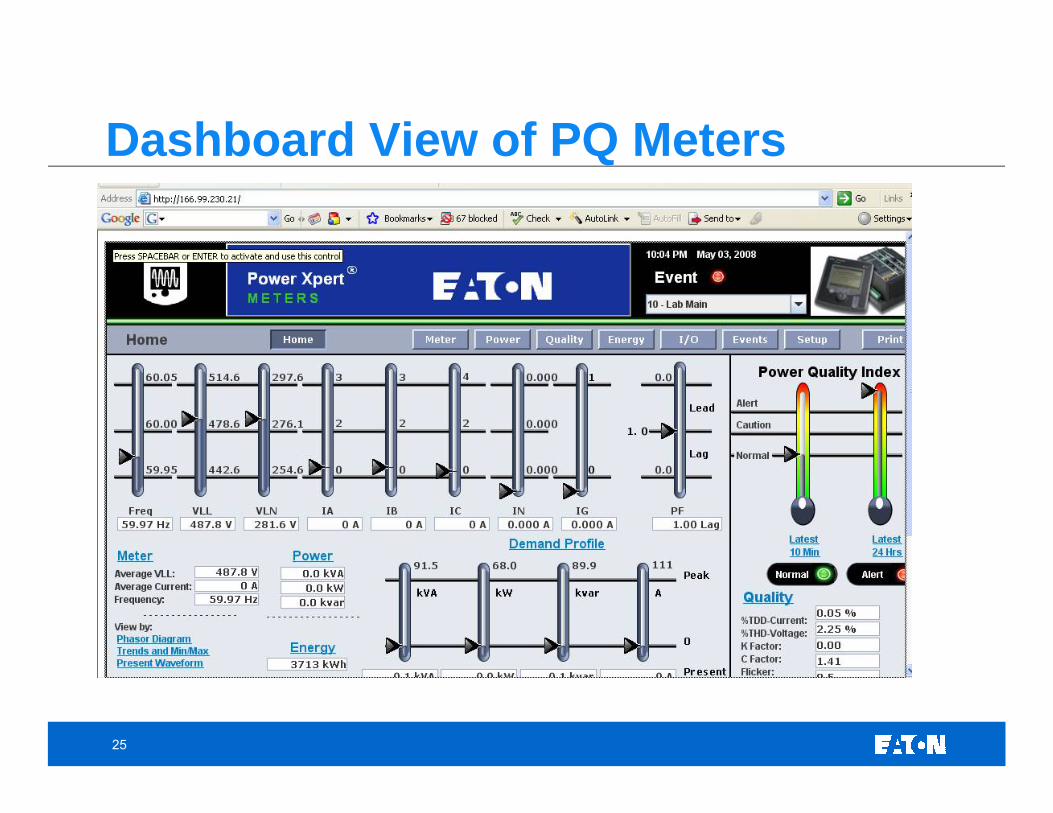
Dashboard View of PQ Meters
26
The most important requirement is the sampling rate.
Many people have thought that they don’t have a voltage transient problem, when really their monitor could not accurately capture the switching transient.
The sampling rate required should be selected based upon the frequency of interest.
Some users follow the Nyquist theory of having the sampling rate double the frequency of interest. As it is still possible to miss the peak of the transient, one should consider using at least 4 times the frequency of interest – 10X is better.
The monitor should be immune to external sources of error, such as VHF ratios, etc. These signals have been recorded as transients by some monitors.
Potential transformers (PT’s) and current transformers (CT’s), generally are bandwidth limited. They typically cannot pass frequencies higher than 3-5kHz and therefore, should not be relied upon to accurately reproduce the event when transient frequencies exceed these limits.
Special Considerations for Transients
27
• Time and Date Stamp• Current Transducer Phase Shift• CT Ratio and Scaling Capabilities• PT Ratio and Scaling Capabilities• Frequency range of steady state data (i.e. for monitoring output of variable
frequency drives)• RMS Sampling Rates if No Transient Event Occurs• Pre-trigger Data• Post Trigger Data• Time Scaling and Zooming• Full Scale Range of Input Voltage and Current
Other Considerations
28
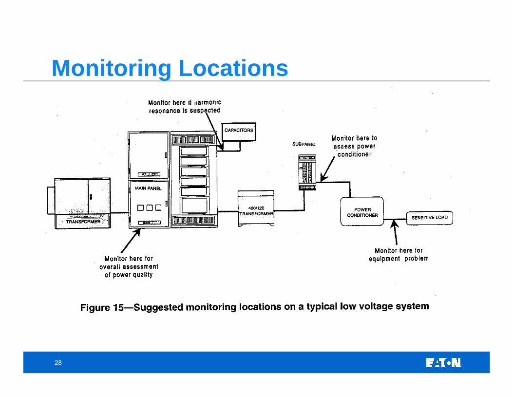
Monitoring Locations
29
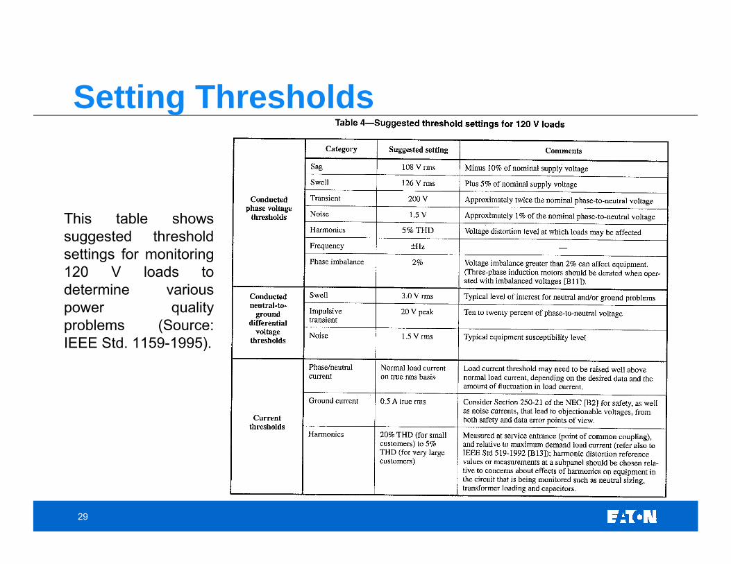
This table shows suggested threshold settings for monitoring 120 V loads to determine various power quality problems (Source: IEEE Std. 1159-1995).
Setting Thresholds
30
Outline• Introduction
• Describing a Power Quality Waveform • Sample PQ Monitoring Videos• Sample PQ Waveforms
• Monitoring Equipment • PQ Definitions • Power Quality Issues and Expected Waveforms
• Voltage Variations• Transients• Harmonics• Wiring and Grounding Considerations
• Power Quality Lab Overview• Final Exam
31
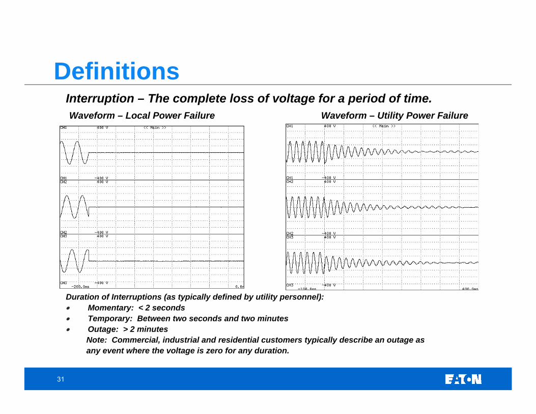
Interruption – The complete loss of voltage for a period of time. Waveform – Local Power Failure Waveform – Utility Power Failure
Duration of Interruptions (as typically defined by utility personnel):• Momentary: < 2 seconds• Temporary: Between two seconds and two minutes• Outage: > 2 minutes
Note: Commercial, industrial and residential customers typically describe an outage as any event where the voltage is zero for any duration.
Definitions
32
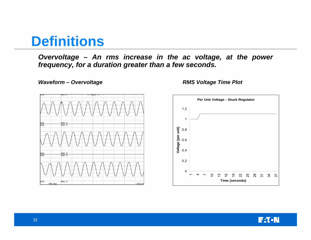
Overvoltage – An rms increase in the ac voltage, at the power frequency, for a duration greater than a few seconds.
Waveform – Overvoltage RMS Voltage Time Plot
Per Unit Voltage - Stuck Regulator
0
0.2
0.4
0.6
0.8
1
1.2
1 4 7 10 13 16 19 22 25 28 31 34 37
Time (seconds)Vo
ltage
(per
uni
t)
Definitions
33
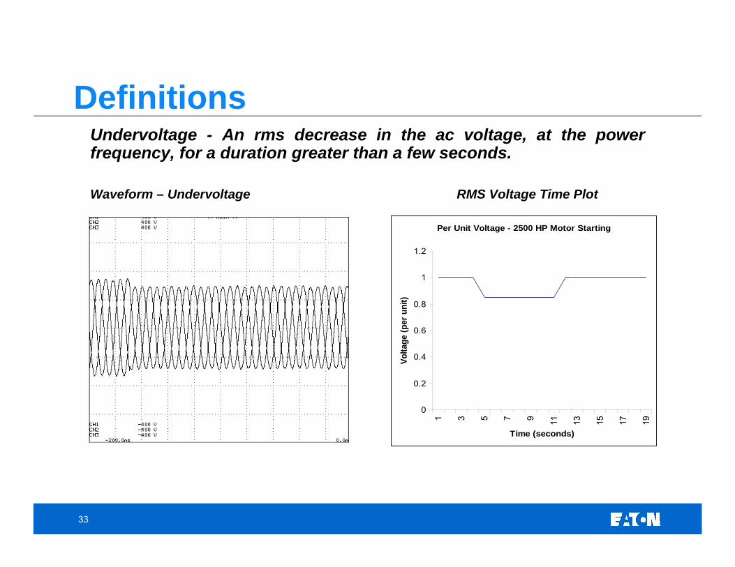
Undervoltage - An rms decrease in the ac voltage, at the power frequency, for a duration greater than a few seconds.
Waveform – Undervoltage RMS Voltage Time Plot
Per Unit Voltage - 2500 HP Motor Starting
0
0.2
0.4
0.6
0.8
1
1.2
1 3 5 7 9 11 13 15 17 19
Time (seconds)
Volta
ge (p
er u
nit)
Definitions
34
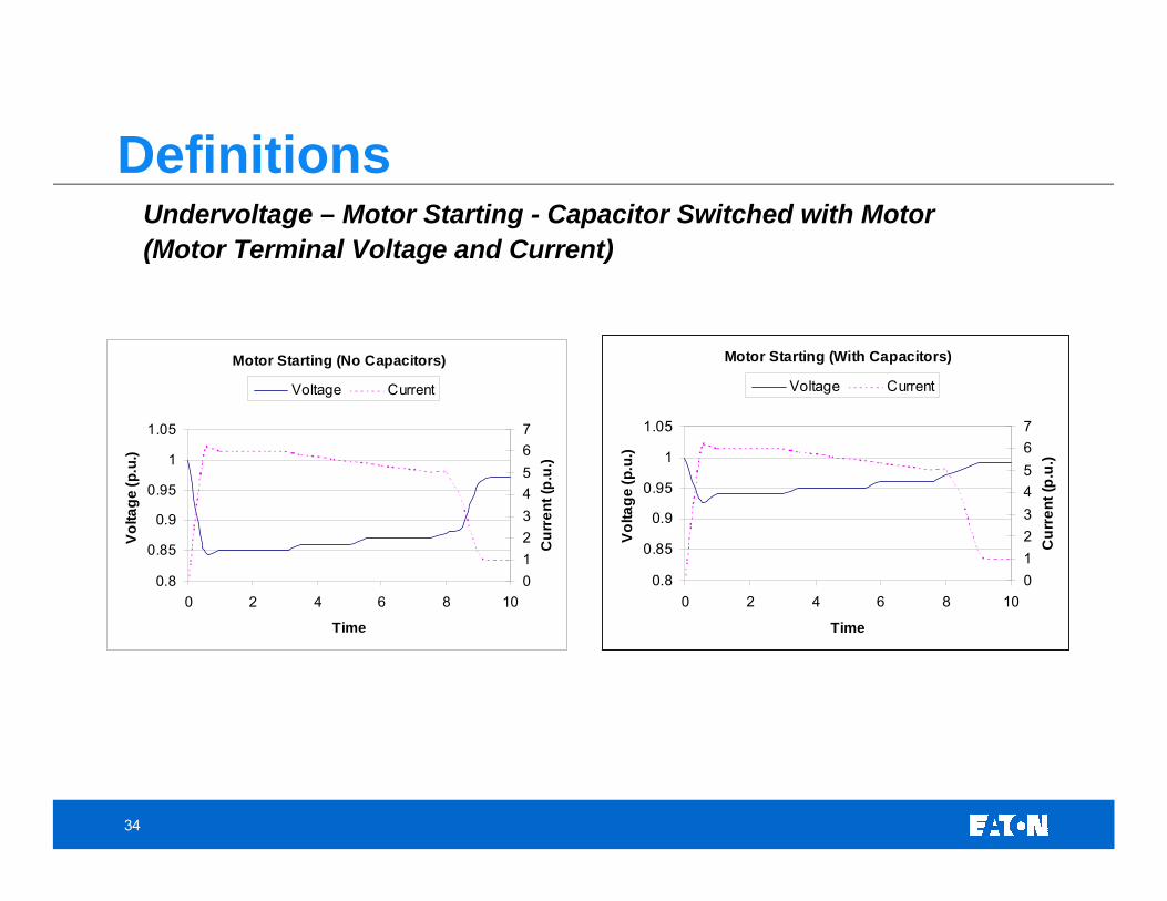
Undervoltage – Motor Starting - Capacitor Switched with Motor(Motor Terminal Voltage and Current)
Motor Starting (No Capacitors)
0.8
0.85
0.9
0.95
1
1.05
0 2 4 6 8 10
Time
Vol
tage
(p.u
.)
01234567
Cur
rent
(p.u
.)
Voltage Current
Motor Starting (With Capacitors)
0.8
0.85
0.9
0.95
1
1.05
0 2 4 6 8 10
TimeV
olta
ge (p
.u.)
01234567
Cur
rent
(p.u
.)
Voltage Current
Definitions
35
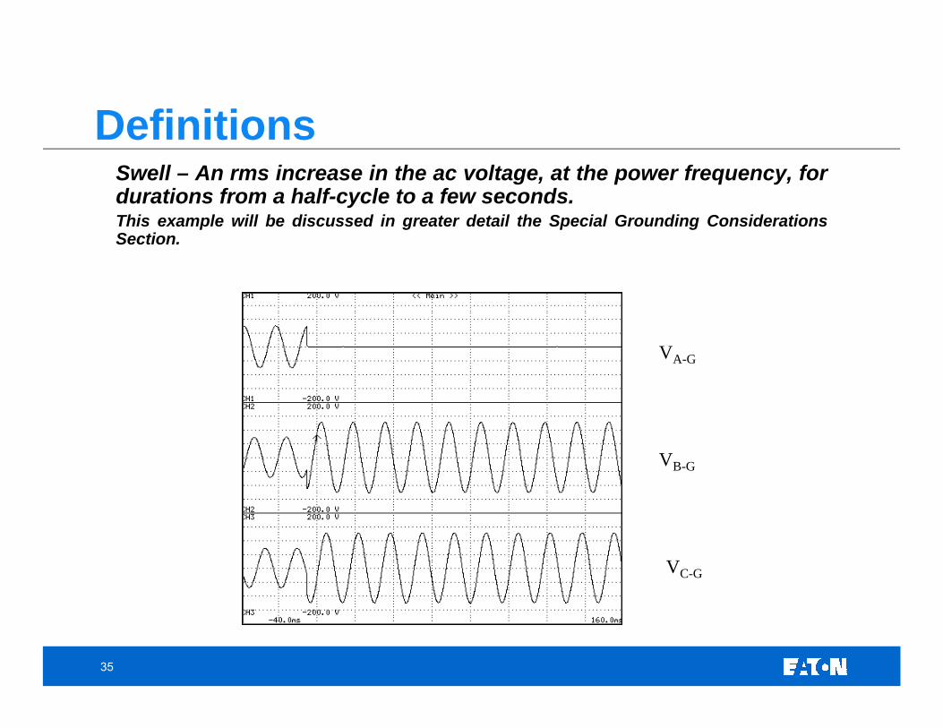
Swell – An rms increase in the ac voltage, at the power frequency, for durations from a half-cycle to a few seconds.This example will be discussed in greater detail the Special Grounding Considerations Section.
VC-G
VA-G
VB-G
Definitions
36
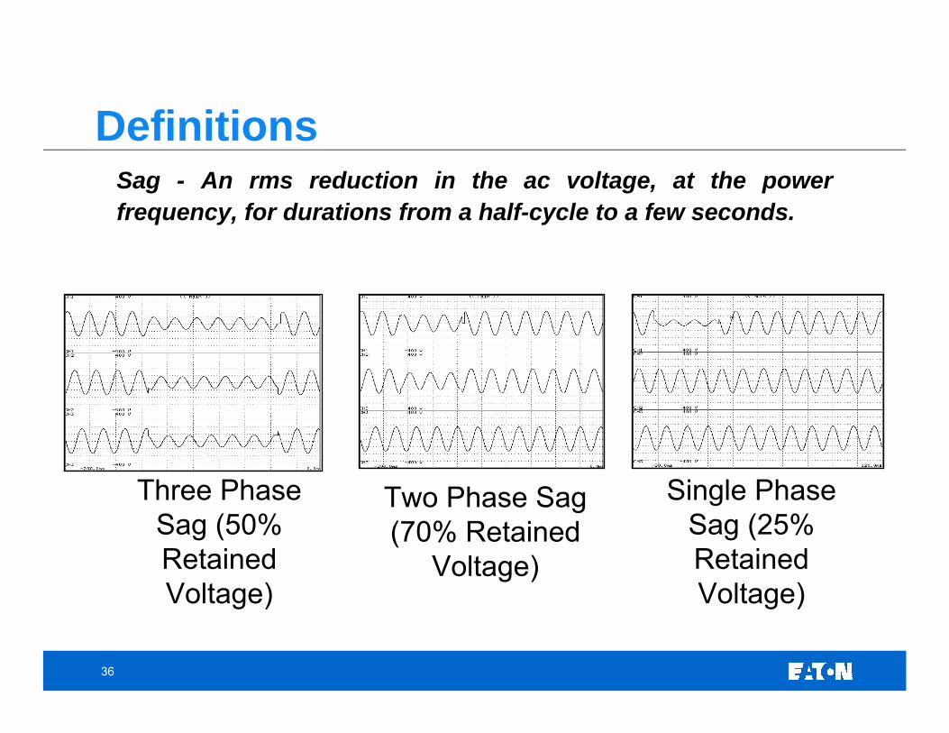
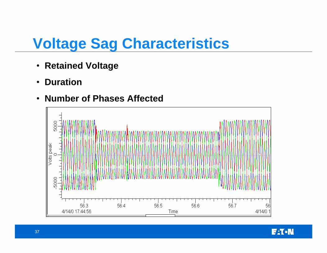
Sag - An rms reduction in the ac voltage, at the power frequency, for durations from a half-cycle to a few seconds.
Three Phase Sag (50% Retained Voltage)
Two Phase Sag (70% Retained
Voltage)
Single Phase Sag (25% Retained Voltage)
Definitions
37
• Retained Voltage
• Duration
• Number of Phases Affected
Voltage Sag Characteristics
38
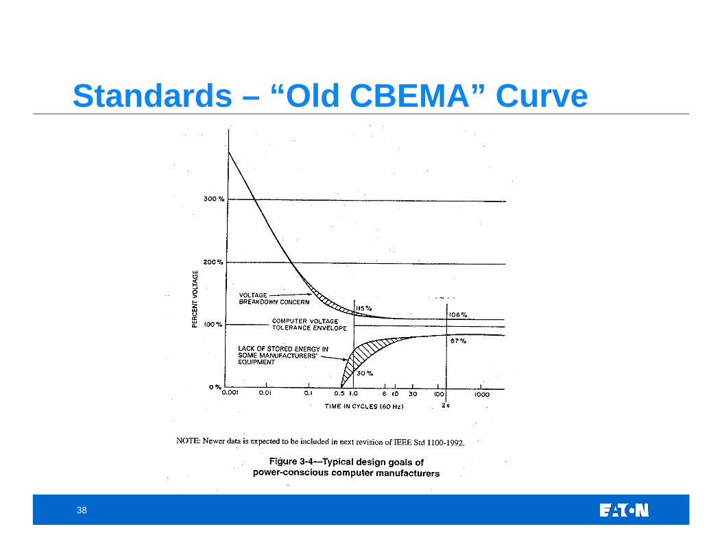
Standards – “Old CBEMA” Curve
39
1 us 3 ms 20 ms 0.5s 10s STEADY
100
0
200
300
400
500
PER
CE
NT
OF
NO
MIN
AL
VO
LTAG
E (R
MS
OR
PE A
K EQ
UIV
ALEN
T)
DURATION OF DISTURBANCES IN CYCLES (c) AND SECONDS (s) ON A 60HZ BASIS
STATE1 ms
110120
140
40
908070
VOLTAGE-TOLERANCEENVELOPE
APPLICABLE TO 120, 120/208, AND120/240 NOMINAL VOLTAGES
A1B
C
D
E1E2
F
H1
H2
D
A2G
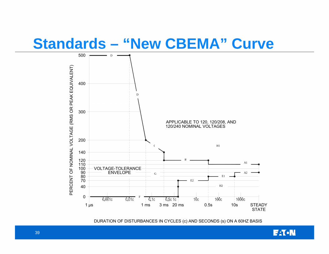
Standards – “New CBEMA” Curve
40
Boundary A – These two lines define the acceptable steady-state voltage range. The range is +/- 10% of nominal voltage. Within this range, equipment should be able to tolerate this voltage continuously.
Boundary B – This boundary defines a voltage swell with a magnitude up to 120% of nominal voltage and duration up to 0.5 seconds. Such a voltage swell is generally the result of a significant reduction in load or when regulation is poor such as from alternate generation sources.
Boundary C – This boundary defines tolerance for typical low-frequency ringwaves such as utility capacitor switching. The frequency of the oscillation may range from 200 Hz to 5 kHz. This boundary includes transients that range from 140% (at 200 Hz) to 200% (at 5 kHz).
Boundary D – This boundary limits high frequency transients typically the result of induced effects from lightning or may be related to high frequency transients generated on the low voltage system. The waveforms characterized in this boundary are described by ANSI/IEEE C62.41-1991. The intent of the range covered by this boundary is to provide 80 Joule minimum transient immunity.
Boundary E – This boundary covers two different types of voltage sags. The first type of sag (E1) is related to application of large loads (motor starting, etc.). These sags are generally shallow (>80% retained voltage) but their duration is long (up to 10 seconds). The second type of sag (E2) is typically related to faults on the power system. This boundary is defined as a retained voltage of 70% and duration up to 0.5 seconds.
Boundary F – A complete loss of voltage is defined by this boundary. An interruption of up to 20 mS is acceptable. If a fault occurs on a power system, fast acting fuses or low voltage circuit breakers will clear a fault within this time and a very deep voltage sag near 0 V (retained voltage) may occur. In addition, reclosing operations that may occur on a power system will account for other occurrences of zero volts for this short period of time.
Region G – The shaded region inside all of the boundaries is the No Damage Region. Within these boundaries, normal operation of information technology equipment (ITE) is expected.
Region H – The Prohibited Regions are the areas outside Boundaries A-F. H1 defines the area above boundaries A1, B, C, and D and Region H2 defines the area below Boundaries A2, E1, E2, and F.
Standards – “New CBEMA” Curve
41
%N
omin
al V
olta
ge (R
MS
or
Peak
Equ
ival
ent)
1µs 1ms 3ms 20ms 0.5s 10s
Safe RegionSafe Region
Equipment Disruptionor Damage Region
500500
400400
300300
200200
100100
00
SagRegion
Motor Starting
SteadyState
ITIC Curve: Voltage-Tolerance Envelope
42
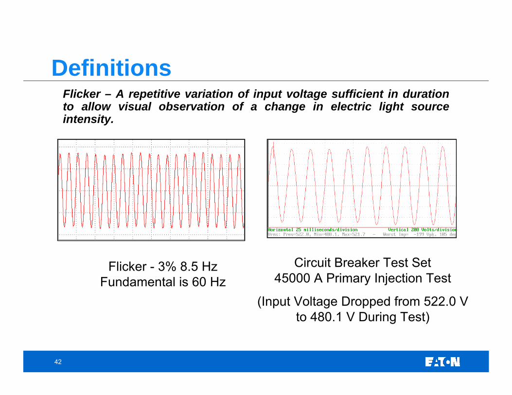
Flicker – A repetitive variation of input voltage sufficient in duration to allow visual observation of a change in electric light sourceintensity.
Flicker - 3% 8.5 Hz Fundamental is 60 Hz
Circuit Breaker Test Set 45000 A Primary Injection Test
(Input Voltage Dropped from 522.0 V to 480.1 V During Test)
Definitions
43
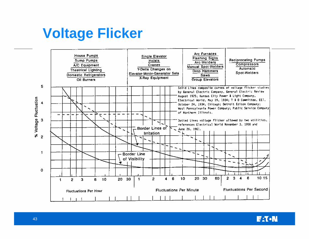
Voltage Flicker
44
Brownout – A reduction of voltage by utility for long duration (hours)
• Often a problem in developing countries or where utility is overloaded
• Utilities will admit that with deregulation, they will push the +/-10% limits
Definitions
45
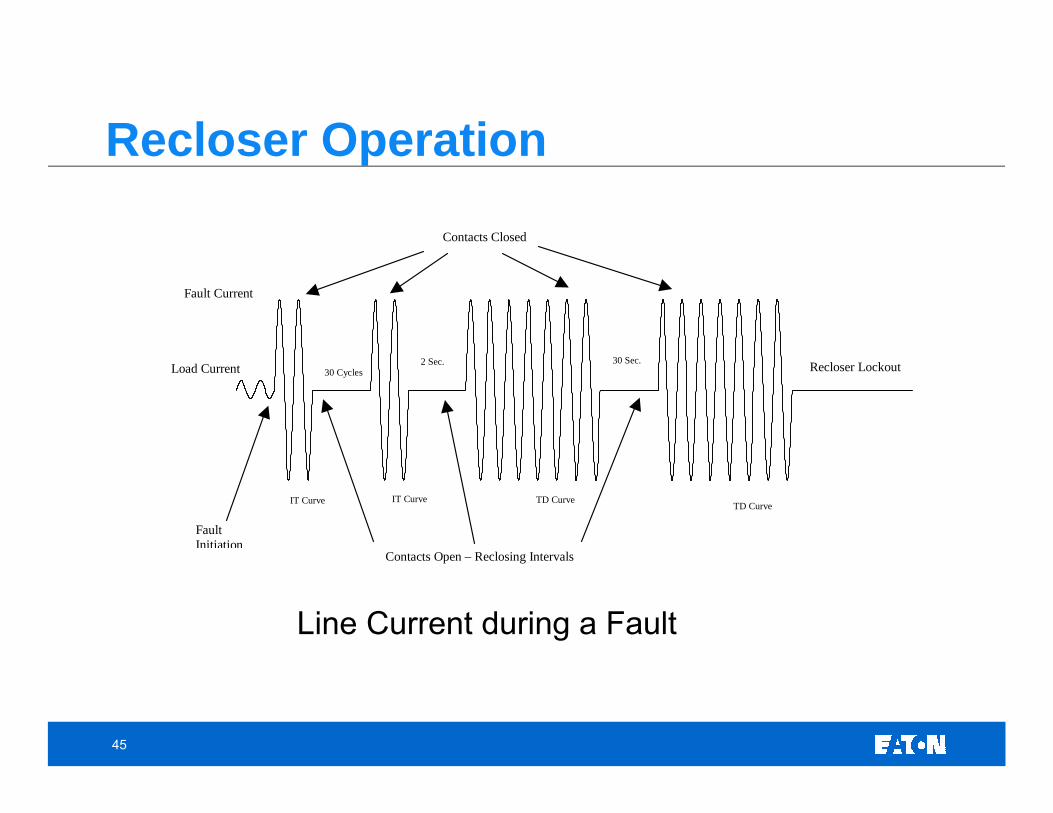
Load Current
Fault Current
Fault Initiation
Contacts Closed
Contacts Open – Reclosing Intervals
Recloser Lockout 30 Cycles 2 Sec. 30 Sec.
IT Curve IT Curve TD Curve TD Curve
Line Current during a Fault
Recloser Operation
46
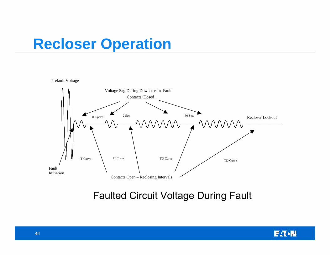
Recloser Operation
Faulted Circuit Voltage During Fault
Prefault Voltage
Voltage Sag During Downstream Fault
Fault Initiation
Contacts Closed
Contacts Open – Reclosing Intervals
Recloser Lockout 30 Cycles 2 Sec. 30 Sec.
IT Curve IT Curve TD Curve TD Curve
47
Impulse Transient - a sudden, non-power frequency change in the steady-state voltage or current, which has a unidirectional polarity.
• Typical duration is nsec to msec.
• Often associated with lightning strikes.
• Because of the high frequencies involved, these types of transients are not conducted very far.
• Impulse transients have been known to excite the natural frequency of the power system and produce oscillatory transients.
Transients
48
Oscillatory Transient - sudden, non-power frequency change in the steady-state voltage or current, that includes both positive and negative polarity values.
• Typical duration can range from 5 usec to 3 msec
• Divided into three types by frequency of the primary frequency component.
− High frequency - primary component over 500 kHz - usually the result of a system response to an impulse transient.
− Medium frequency - primary component between 5 kHz and 500 kHz - often the result of cable switching or back-to-back capacitor bank switching.
− Low frequency - primary component less than 5 kHz - usually the result of capacitor bank switching on a distribution or sub-transmission system.
Transients
49
Low Frequency Oscillatory Transient - sudden, non-power frequency change in the steady-state voltage or current, that includes both positive and negative polarity values – usually caused by utility capacitor switching.
• Distribution capacitor switching will typically produce a transient between 300 Hz and 900 Hz.
• Many utility distribution systems will have a common “ring” frequency due to fact that many utilities reuse construction details such as structure type, conductor type, etc.
• In theory the peak magnitude can be 2.0 p.u., but in reality it tends to fall between 1.3 p.u. and 1.8 p.u. with a duration between 0.5 to 3 cycles. 1.4 p.u. is a typical value.
• Transients below 300 Hz are generally the result of transformer energizationor ferroresonance.
Transients
50
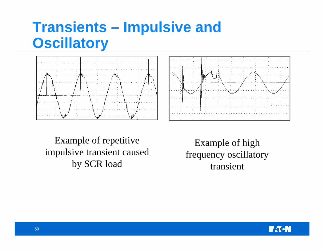
Example of repetitive impulsive transient caused
by SCR load
Example of high frequency oscillatory
transient
Transients – Impulsive and Oscillatory
51
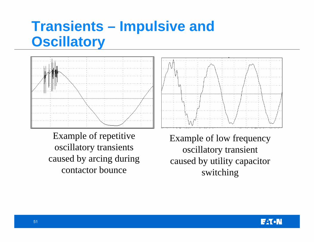
Example of repetitive oscillatory transients
caused by arcing during contactor bounce
Example of low frequency oscillatory transient
caused by utility capacitor switching
Transients – Impulsive and Oscillatory
52
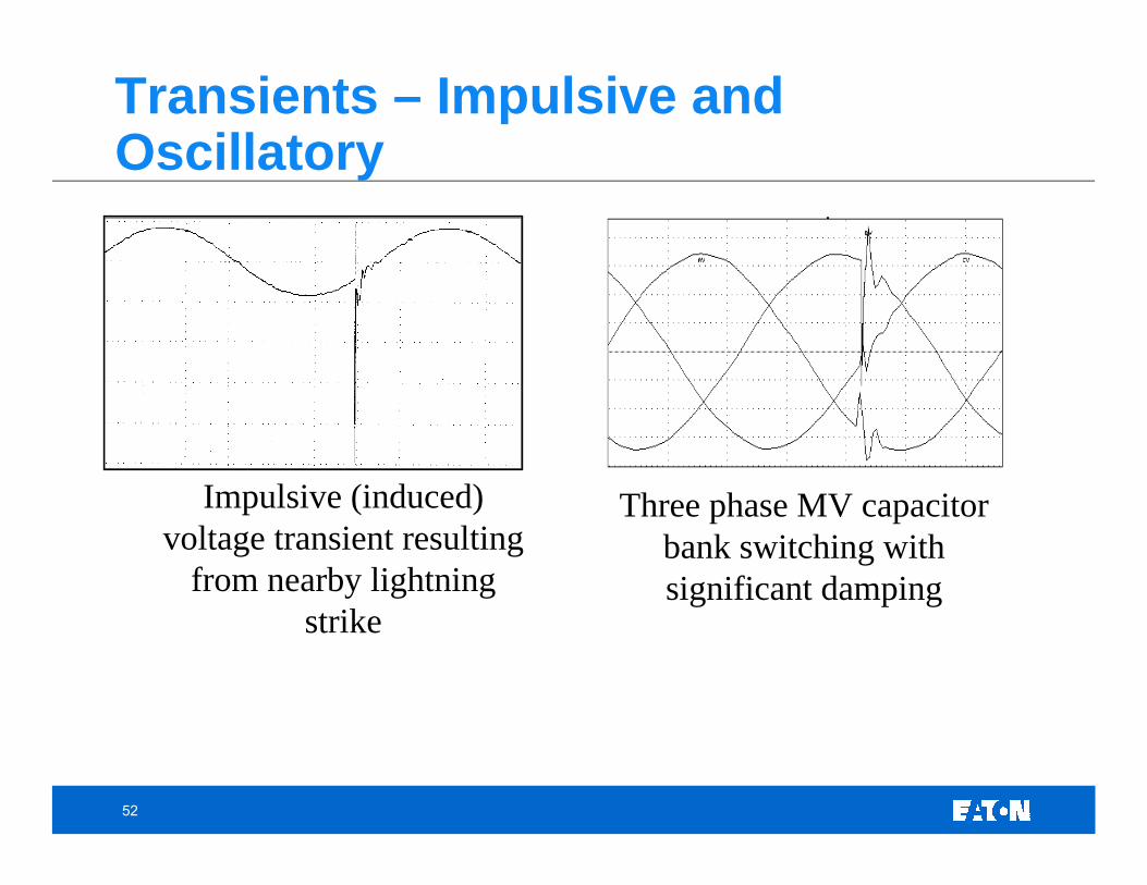
Impulsive (induced) voltage transient resulting
from nearby lightning strike
Three phase MV capacitor bank switching with significant damping
Transients – Impulsive and Oscillatory
53
Outline• Introduction
• Describing a Power Quality Waveform • Sample PQ Monitoring Videos• Sample PQ Waveforms
• Monitoring Equipment • PQ Definitions • Power Quality Issues and Expected Waveforms
• Voltage Variations• Transients• Harmonics• Wiring and Grounding Considerations
• Power Quality Lab Overview• Final Exam
54
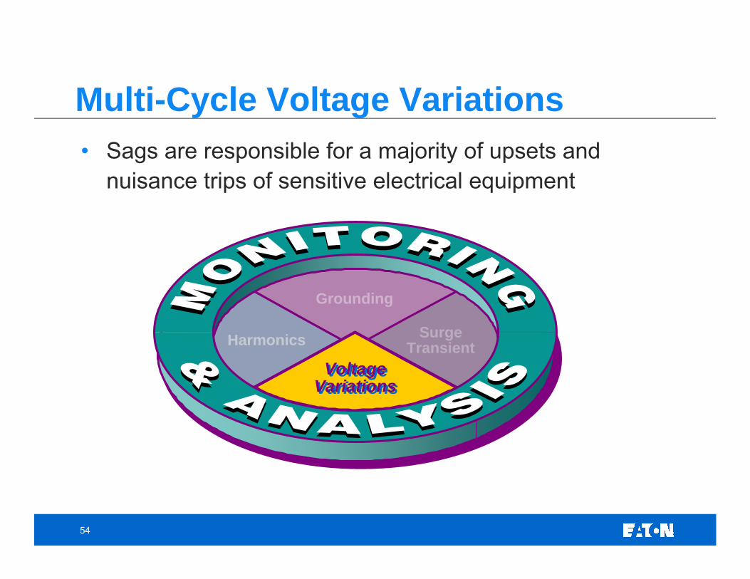
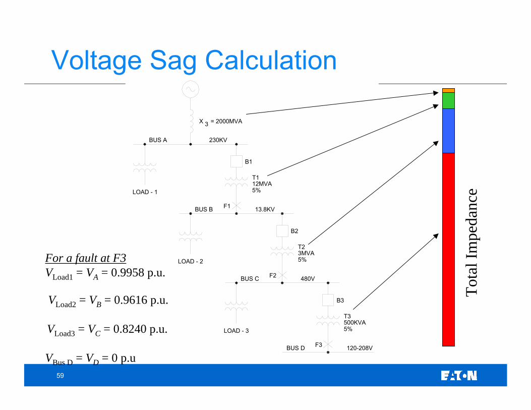
• Sags are responsible for a majority of upsets and nuisance trips of sensitive electrical equipment
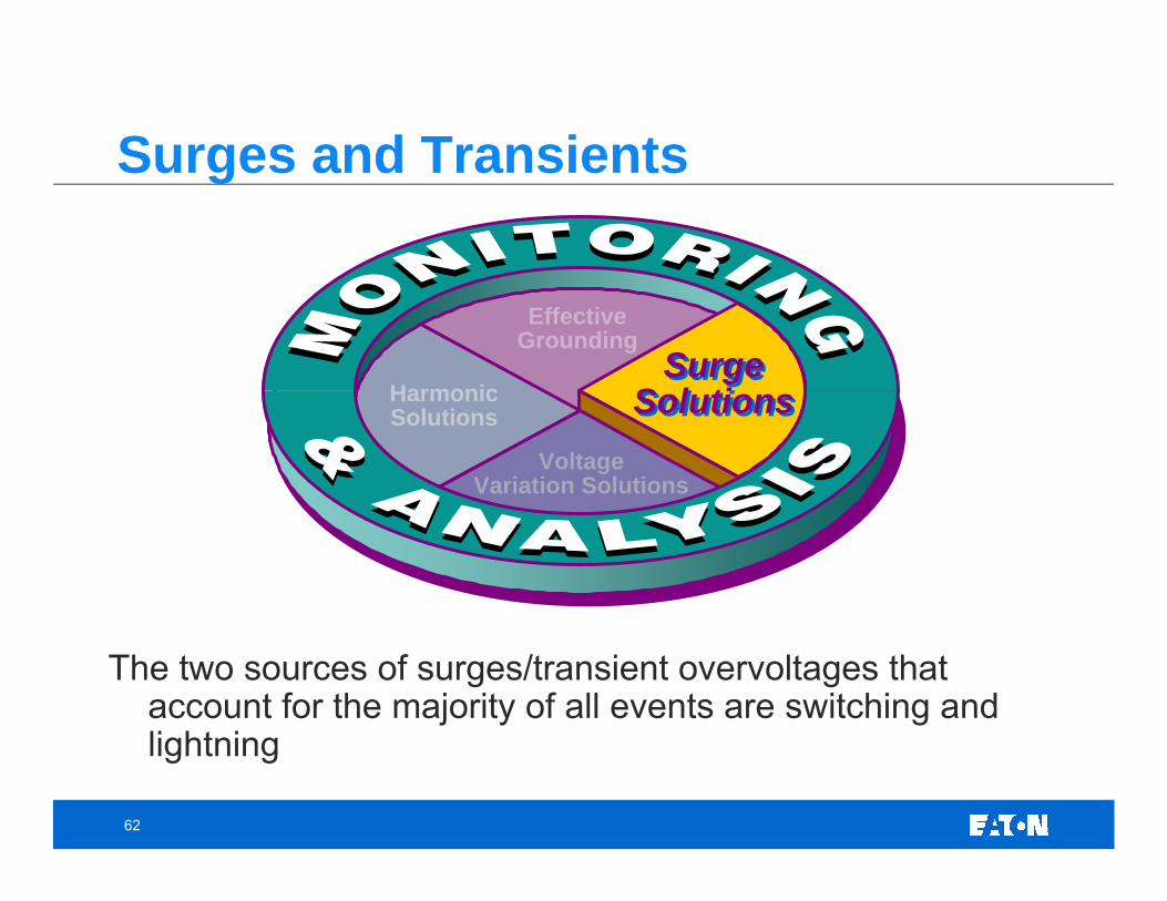
The two sources of surges/transient overvoltages that account for the majority of all events are switching and lightning
EffectiveGrounding
SurgeSolutions
SurgeSolutionsHarmonic
Solutions
VoltageVariation Solutions
Surges and Transients
63
• Monitoring Techniques for Surges and Transients.
• Explore the capabilities of the various meters to capture transients.
• Quantify the protection afforded by surge protective devices (SPDs).
• Investigate the affect of lead length on let-thru voltage of the SPD.
Monitoring Transients - Outline
64
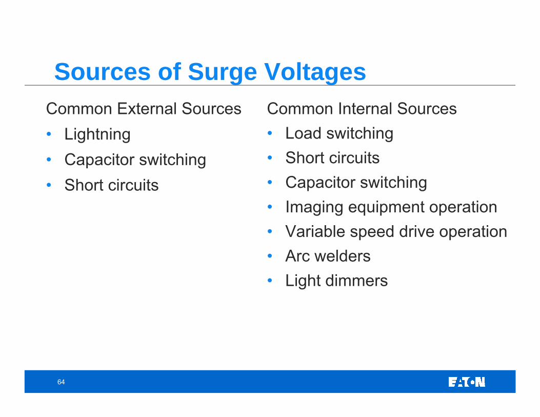
Common External Sources• Lightning• Capacitor switching• Short circuits
Common Internal Sources• Load switching• Short circuits• Capacitor switching• Imaging equipment operation• Variable speed drive operation• Arc welders• Light dimmers
Sources of Surge Voltages
65
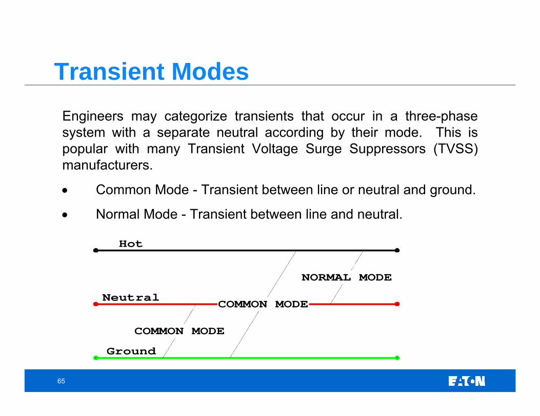
Engineers may categorize transients that occur in a three-phase system with a separate neutral according by their mode. This ispopular with many Transient Voltage Surge Suppressors (TVSS) manufacturers.
• Common Mode - Transient between line or neutral and ground.
• Normal Mode - Transient between line and neutral.
• Oscillatory transients approaching 2.0 p.u. will not generally cause insulation damage. Transients can be magnified if the conditions are right on the low voltage side to between 3.0 to 4.0 p.u.
• Voltage magnification can occur if the low side resonant frequency closely matches the switching frequency of the capacitor bank.
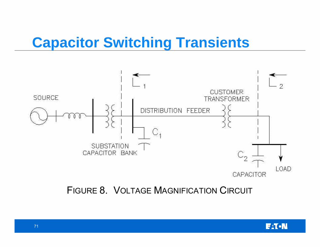
Capacitor Switching – Voltage Magnification
69
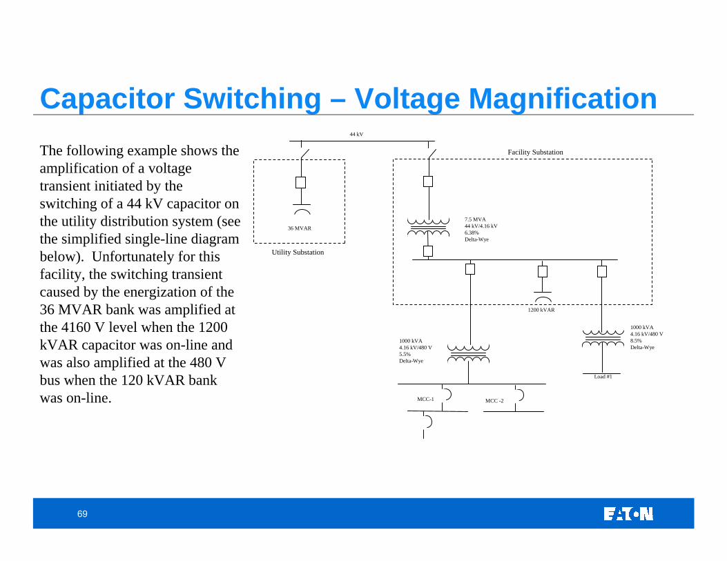
1000 kVA4.16 kV/480 V8.5% Delta-Wye
7.5 MVA44 kV/4.16 kV6.38%Delta-Wye
44 kV
1000 kVA4.16 kV/480 V5.5%Delta-Wye
1200 kVAR
Load #1
MCC -2MCC-1
36 MVAR
Facility Substation
Utility Substation
The following example shows the amplification of a voltage transient initiated by the switching of a 44 kV capacitor on the utility distribution system (see the simplified single-line diagram below). Unfortunately for this facility, the switching transient caused by the energization of the 36 MVAR bank was amplified at the 4160 V level when the 1200 kVAR capacitor was on-line and was also amplified at the 480 V bus when the 120 kVAR bank was on-line.
Capacitor Switching – Voltage Magnification
70
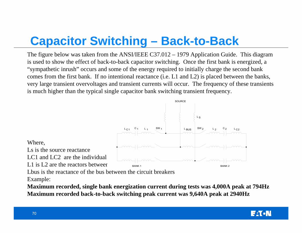
The figure below was taken from the ANSI/IEEE C37.012 – 1979 Application Guide. This diagram is used to show the effect of back-to-back capacitor switching. Once the first bank is energized, a “sympathetic inrush” occurs and some of the energy required to initially charge the second bank comes from the first bank. If no intentional reactance (i.e. L1 and L2) is placed between the banks, very large transient overvoltages and transient currents will occur. The frequency of these transients is much higher than the typical single capacitor bank switching transient frequency.
Where,Ls is the source reactanceLC1 and LC2 are the individual capacitor bank reactancesL1 is L2 are the reactors between each circuit breaker and its switched bankLbus is the reactance of the bus between the circuit breakers Example:Maximum recorded, single bank energization current during tests was 4,000A peak at 794HzMaximum recorded back-to-back switching peak current was 9,640A peak at 2940Hz
SOURCE
L C1 1C 1L SW 1 L BUS SW 2 L 2 C 2 CL 2
L S
BANK 1 BANK 2
Capacitor Switching – Back-to-Back
71
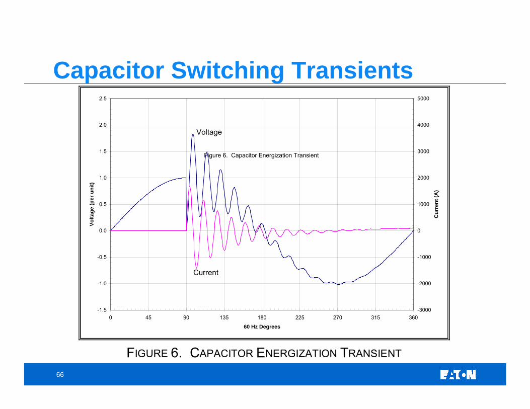
Capacitor Switching Transients
FIGURE 8. VOLTAGE MAGNIFICATION CIRCUIT
72
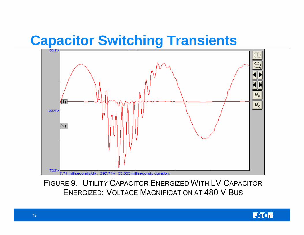
Capacitor Switching Transients
FIGURE 9. UTILITY CAPACITOR ENERGIZED WITH LV CAPACITOR ENERGIZED: VOLTAGE MAGNIFICATION AT 480 V BUS
73
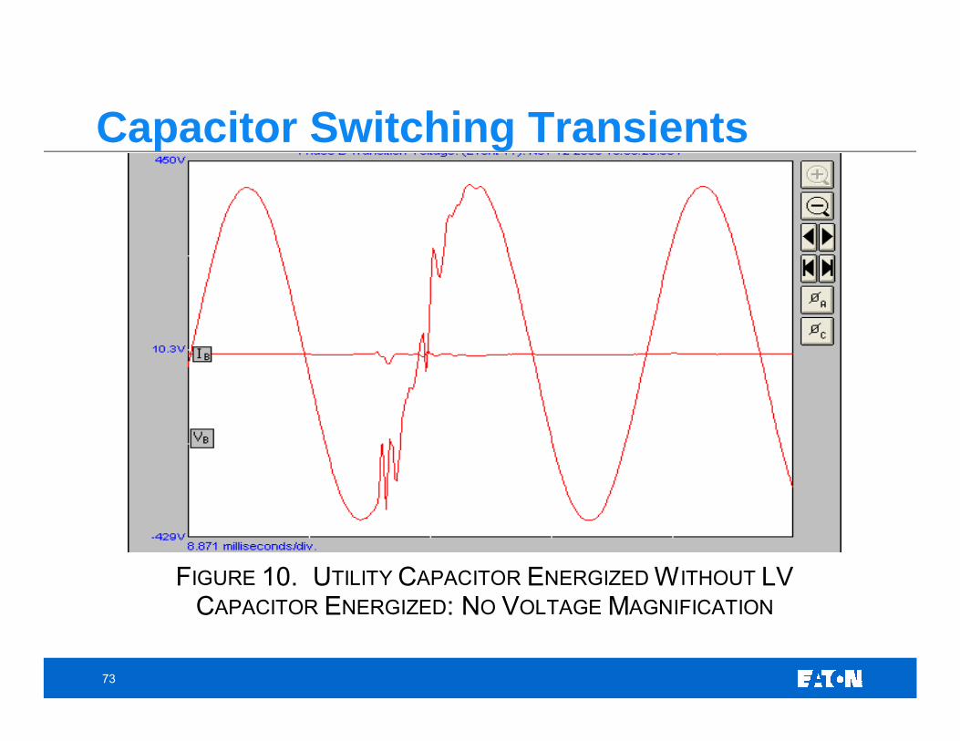
Capacitor Switching Transients
FIGURE 10. UTILITY CAPACITOR ENERGIZED WITHOUT LV CAPACITOR ENERGIZED: NO VOLTAGE MAGNIFICATION
74
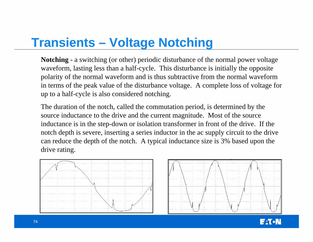
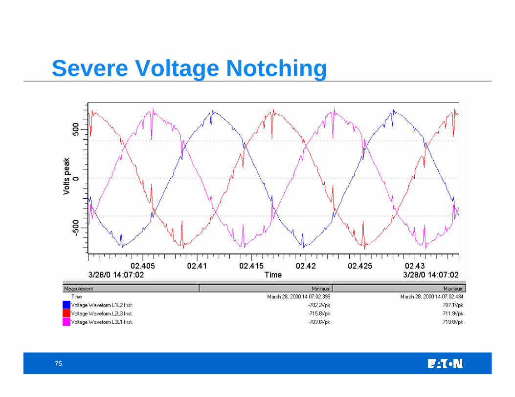
Notching - a switching (or other) periodic disturbance of the normal power voltage waveform, lasting less than a half-cycle. This disturbance is initially the opposite polarity of the normal waveform and is thus subtractive from the normal waveform in terms of the peak value of the disturbance voltage. A complete loss of voltage for up to a half-cycle is also considered notching.
The duration of the notch, called the commutation period, is determined by the source inductance to the drive and the current magnitude. Most of the source inductance is in the step-down or isolation transformer in front of the drive. If the notch depth is severe, inserting a series inductor in the ac supply circuit to the drive can reduce the depth of the notch. A typical inductance size is 3% based upon the drive rating.
Transients – Voltage Notching
75
Severe Voltage Notching
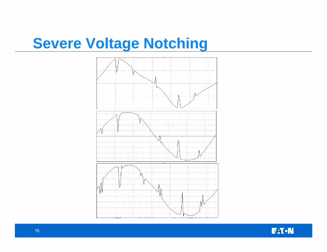
76
Severe Voltage Notching
77
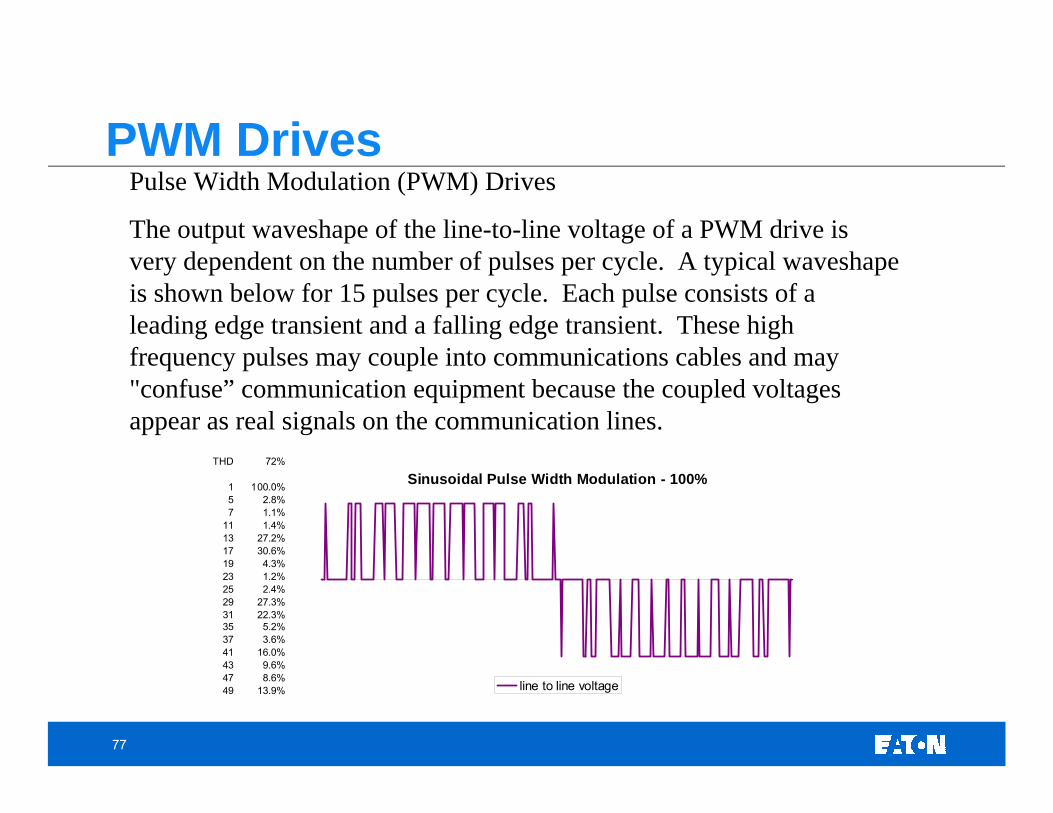
Pulse Width Modulation (PWM) Drives
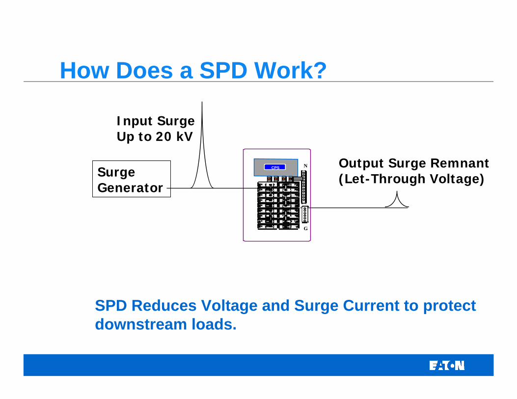
The output waveshape of the line-to-line voltage of a PWM drive is very dependent on the number of pulses per cycle. A typical waveshape is shown below for 15 pulses per cycle. Each pulse consists of a leading edge transient and a falling edge transient. These highfrequency pulses may couple into communications cables and may "confuse” communication equipment because the coupled voltages appear as real signals on the communication lines.
SPD Reduces Voltage and Surge Current to protect downstream loads.
80
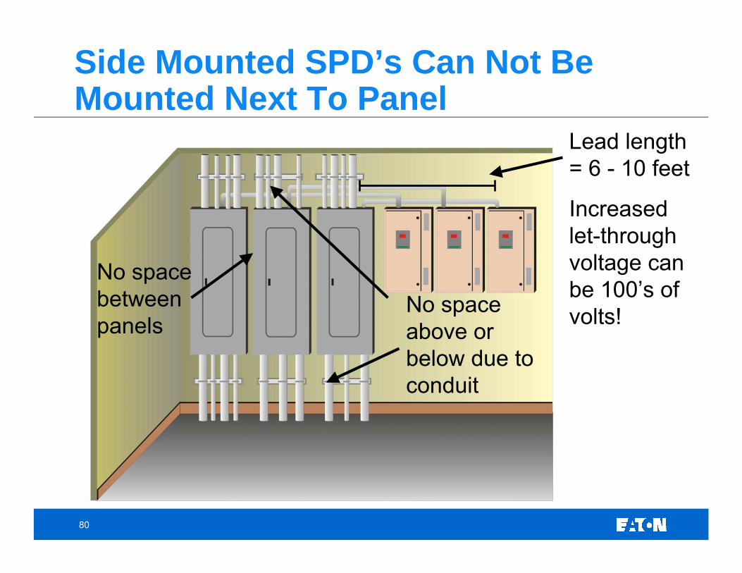
Side Mounted SPD’s Can Not Be Mounted Next To Panel
No space between panels
No space above or below due to conduit
Lead length = 6 - 10 feet
Increased let-through voltage can be 100’s of volts!
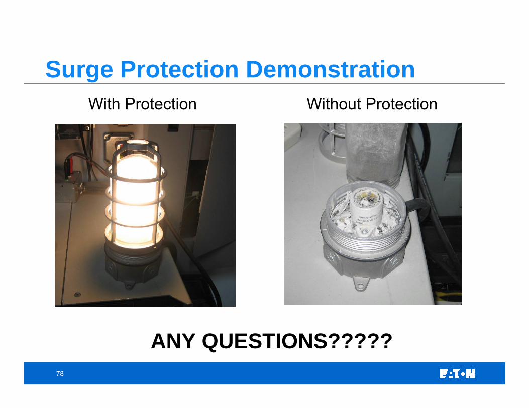
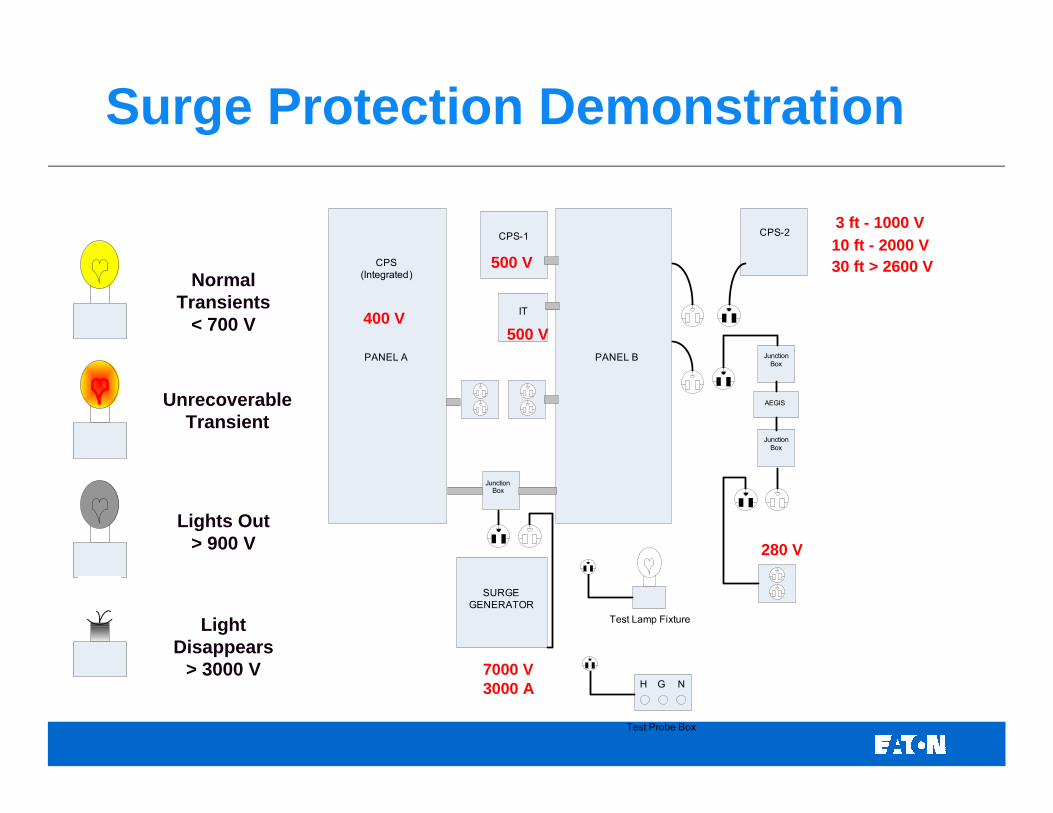
Surge Protection Demonstration
CPS(Integrated)
CPS-1
IT
Junction Box
CPS-2
AEGIS
Junction Box
Junction Box
PANEL A PANEL B
SURGE GENERATOR
H G N
Test Probe Box
Test Lamp Fixture
400 V
280 V
3 ft - 1000 V
500 V
500 V10 ft - 2000 V30 ft > 2600 V
7000 V 3000 A
Normal Transients
< 700 V
Unrecoverable Transient
Lights Out > 900 V
Light Disappears
> 3000 V
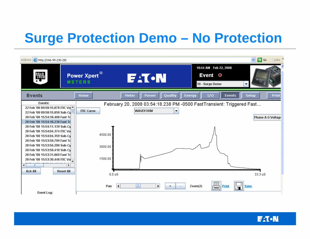
Surge Protection Demo – No Protection
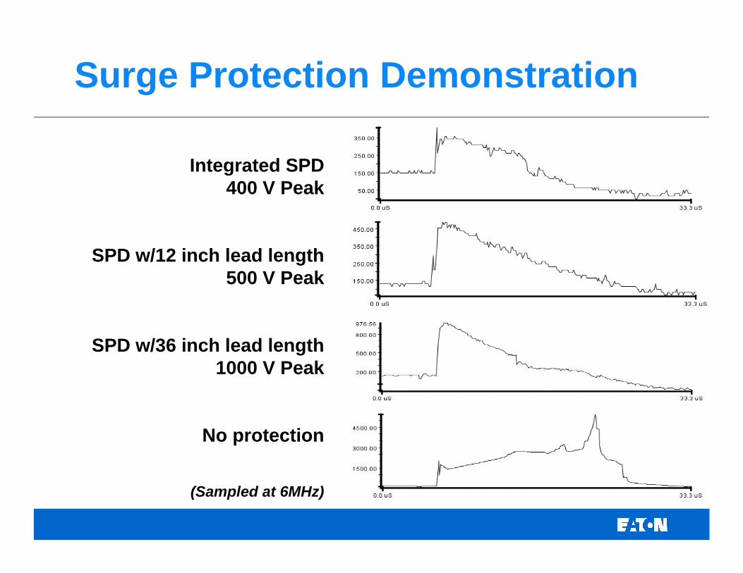
Surge Protection Demonstration
Integrated SPD400 V Peak
SPD w/12 inch lead length500 V Peak
SPD w/36 inch lead length1000 V Peak
No protection
(Sampled at 6MHz)
84
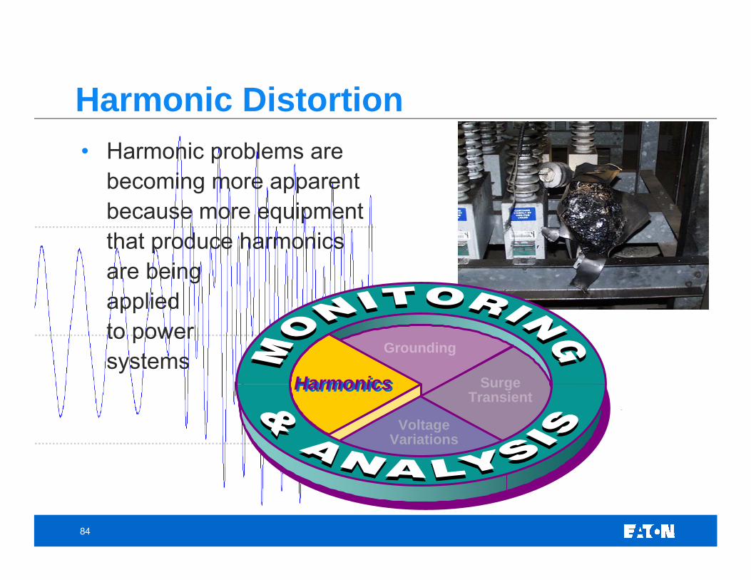
• Harmonic problems are becoming more apparent because more equipment that produce harmonics are being applied to power systems
Grounding
SurgeTransient
HarmonicsHarmonics
VoltageVariations
Harmonic Distortion
85
• Power factor correction capacitors
• Harmonic filter that may be out of service
• Shunt capacitors on the utility supply
• Alternate sources from the utility or a utility transformer out of service
• Different load combinations
• Nearby facilities with significant harmonic generation
• Monitor long enough to cover one complete “business” cycle
Specific Conditions to Consider
86
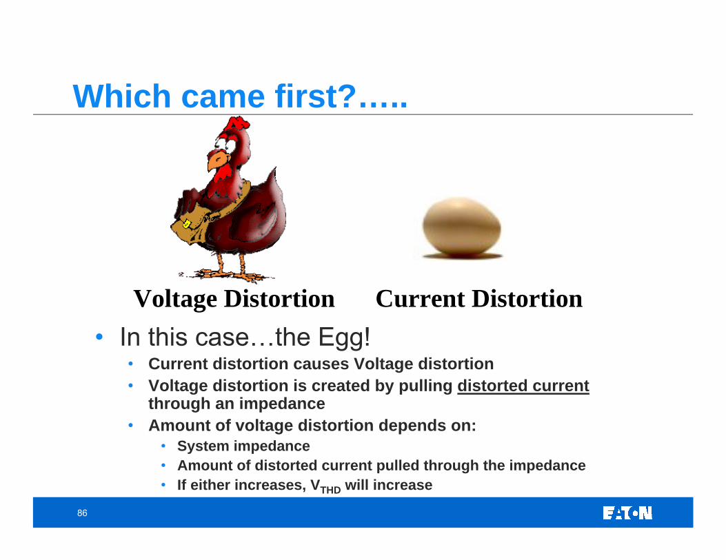
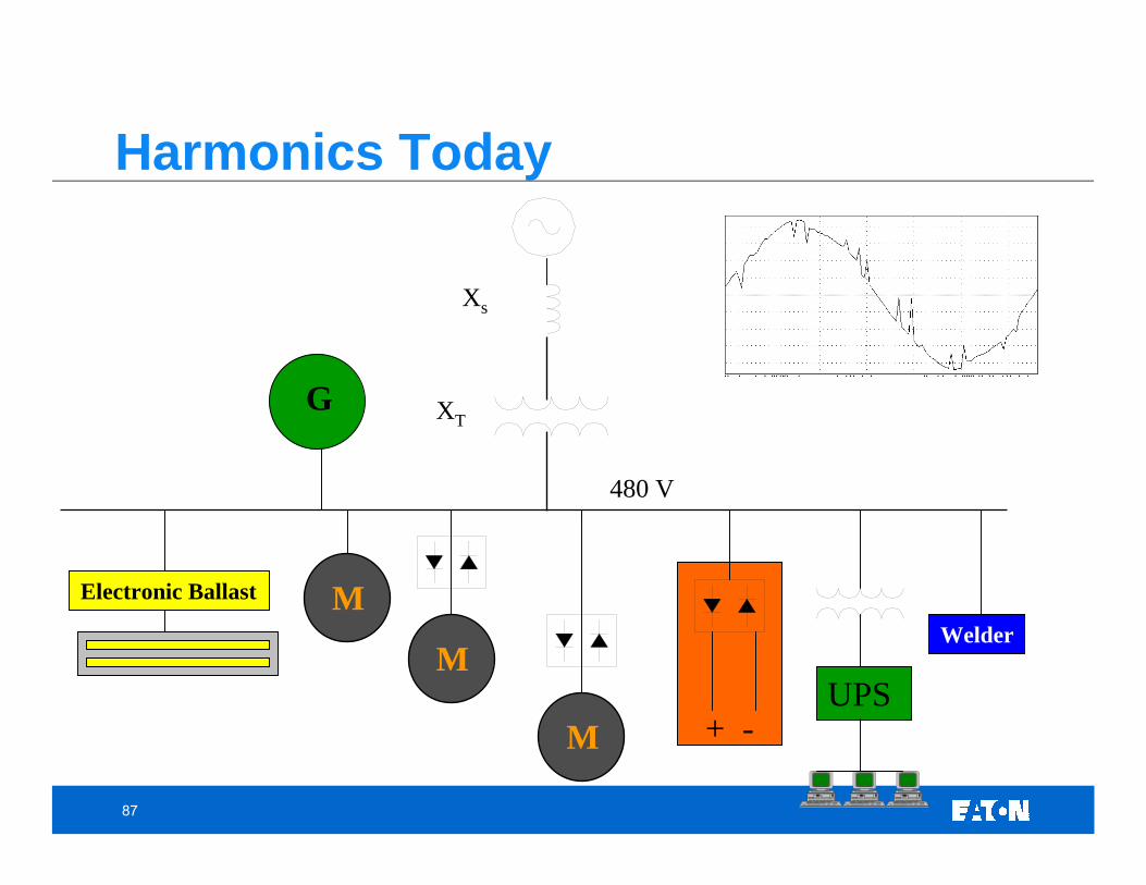
Which came first?…..
• In this case…the Egg!• Current distortion causes Voltage distortion• Voltage distortion is created by pulling distorted current
through an impedance• Amount of voltage distortion depends on:
• System impedance• Amount of distorted current pulled through the impedance• If either increases, VTHD will increase
Voltage Distortion Current Distortion
87
Harmonics Today
480 V
Xs
M
XT
+ -M
G
UPS
Welder
Electronic Ballast M
88
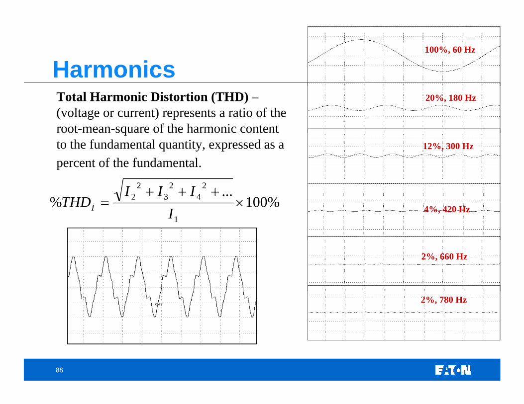
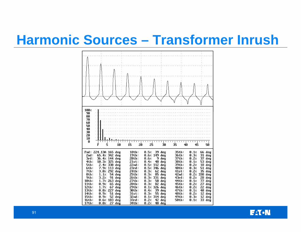
100%, 60 Hz
2%, 780 Hz
20%, 180 Hz
12%, 300 Hz
4%, 420 Hz
2%, 660 Hz
%100...
%1
24
23
22 ×
+++=
IIII
THDI
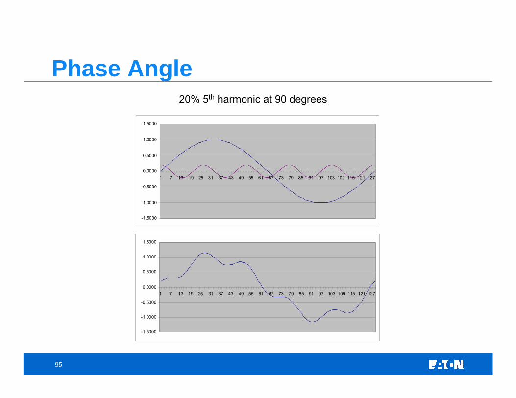
Total Harmonic Distortion (THD) –(voltage or current) represents a ratio of the root-mean-square of the harmonic content to the fundamental quantity, expressed as a percent of the fundamental.
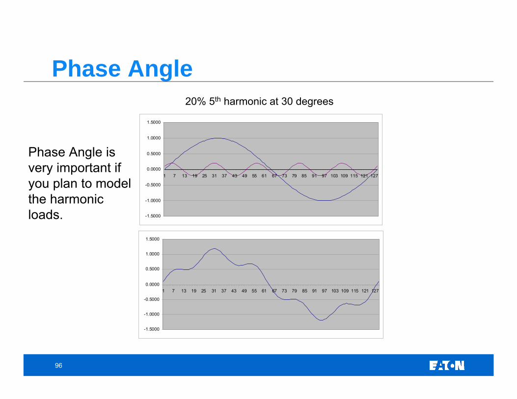
Phase Angle is very important if you plan to model the harmonic loads.
97
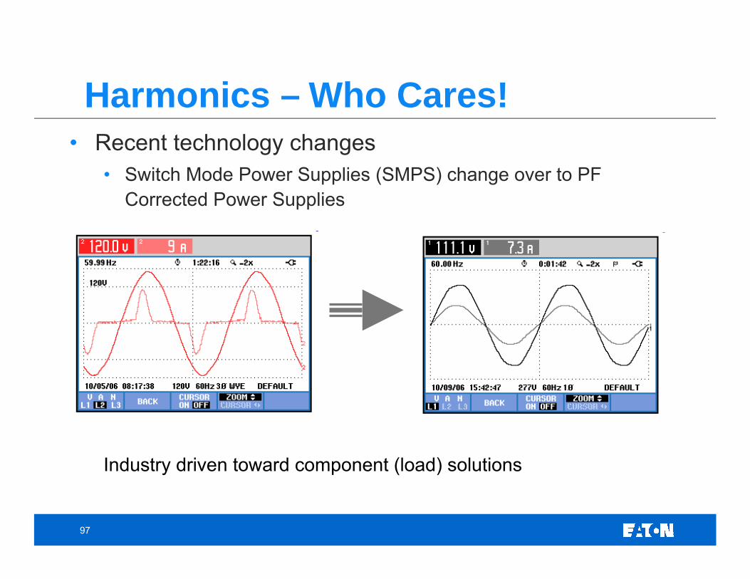
Harmonics – Who Cares!• Recent technology changes
• Switch Mode Power Supplies (SMPS) change over to PF Corrected Power Supplies
Industry driven toward component (load) solutions
98
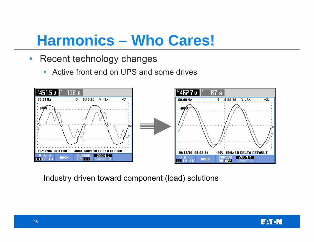
Harmonics – Who Cares!• Recent technology changes
• Active front end on UPS and some drives
Industry driven toward component (load) solutions
99
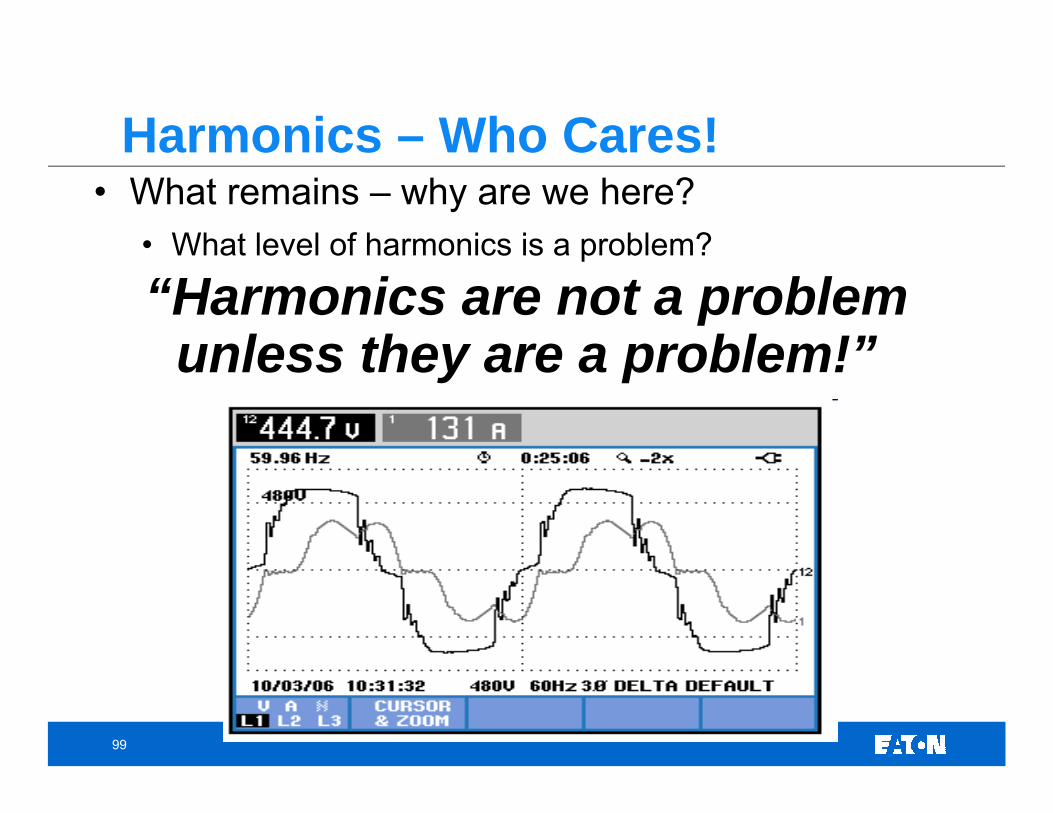
Harmonics – Who Cares!• What remains – why are we here?
• What level of harmonics is a problem?
“Harmonics are not a problem unless they are a problem!”
100
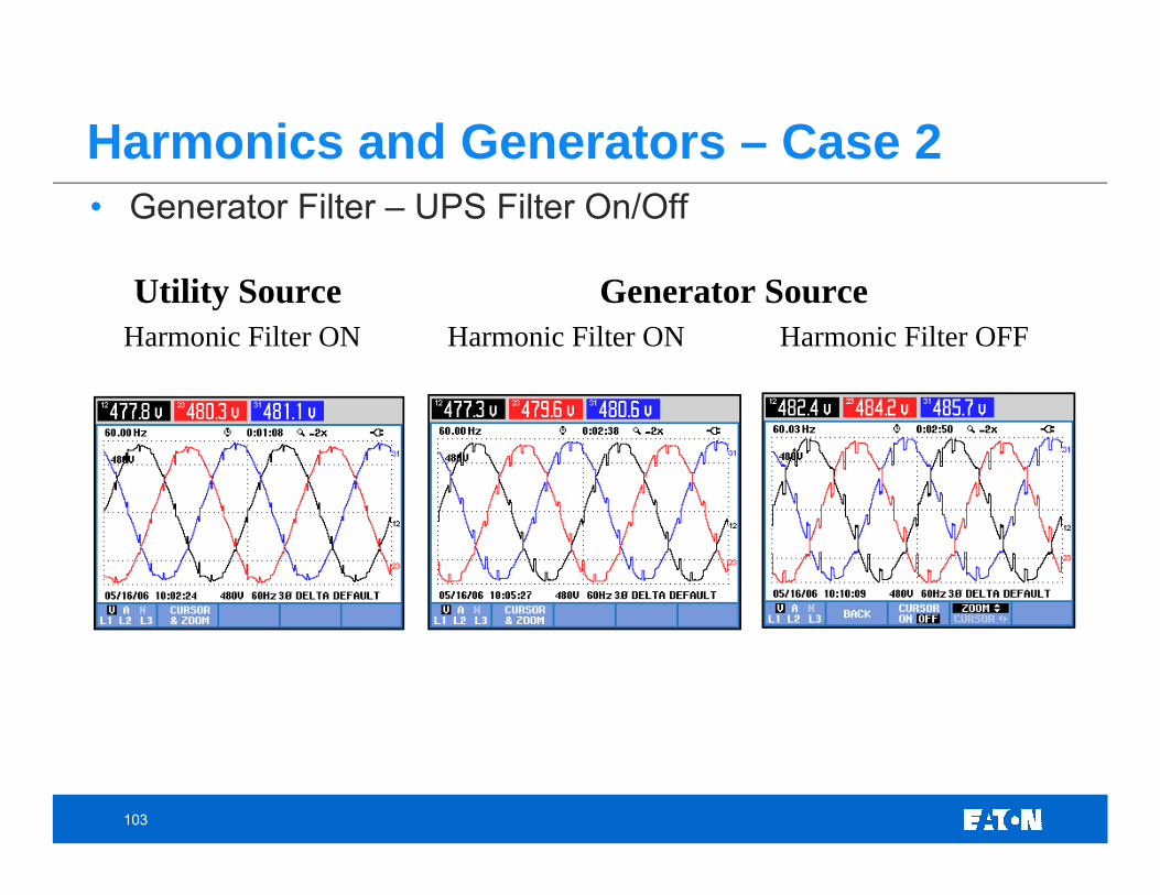
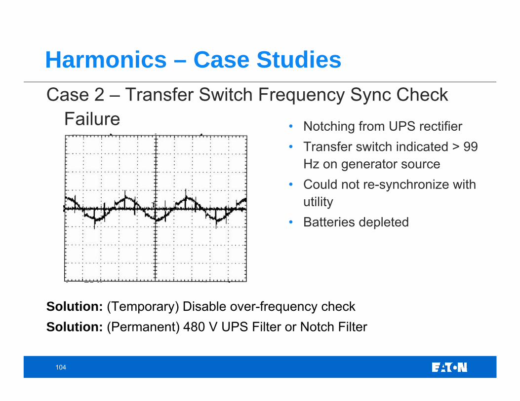
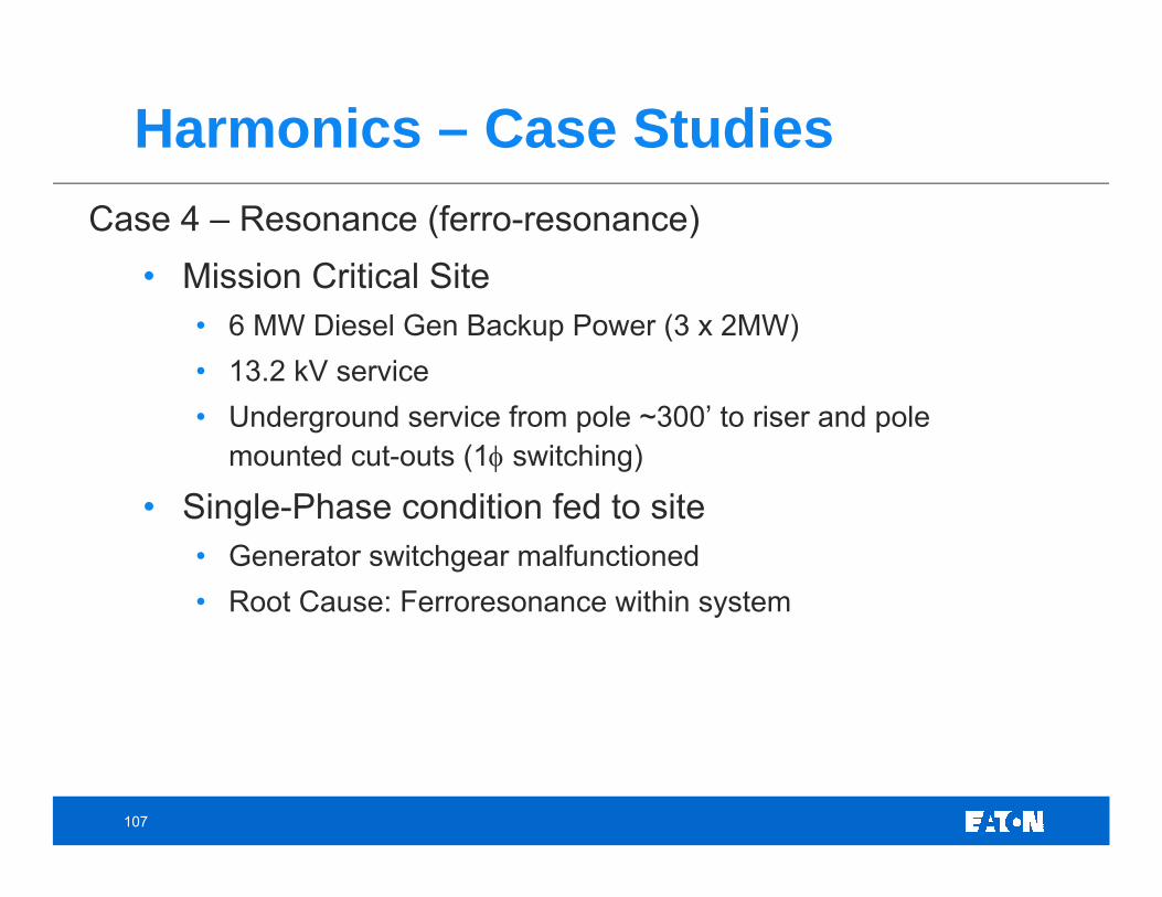
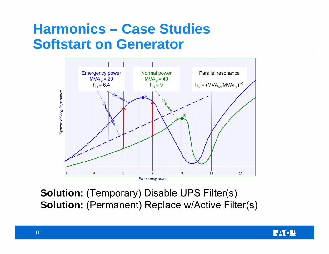
Harmonics – Case Studies
Case Studies• Case 1 – Generator Sync Failure• Case 2 – Transfer Switch Frequency Sync Check Failure• Case 3 – Small Single-Phase Examples• Case 4 – Ferroresonance Example• Case 5 – UPS Filter Parallel Resonance
101
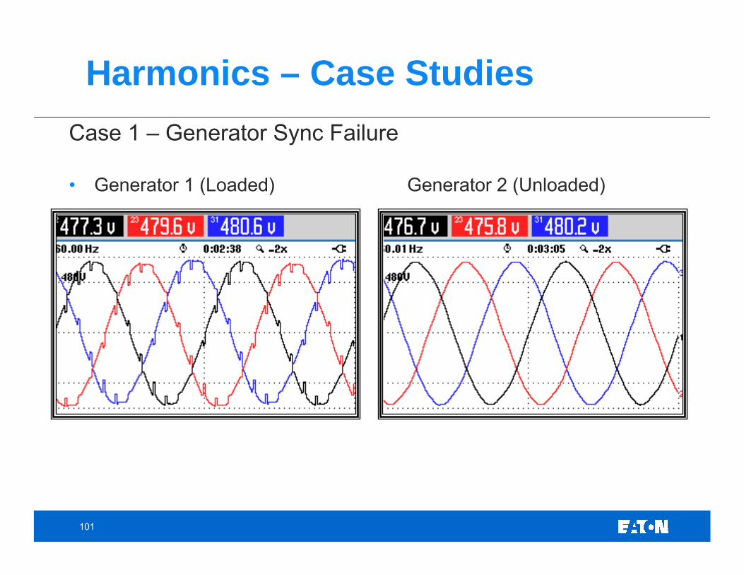
Harmonics – Case StudiesCase 1 – Generator Sync Failure
• Generator 1 (Loaded) Generator 2 (Unloaded)
102
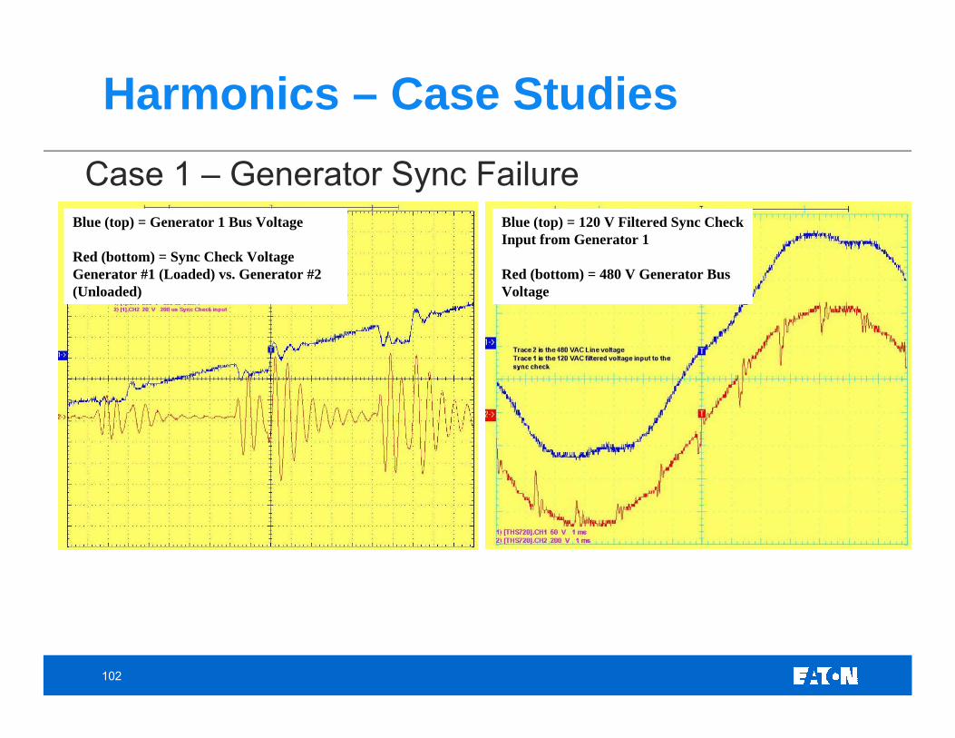
Harmonics – Case StudiesCase 1 – Generator Sync Failure
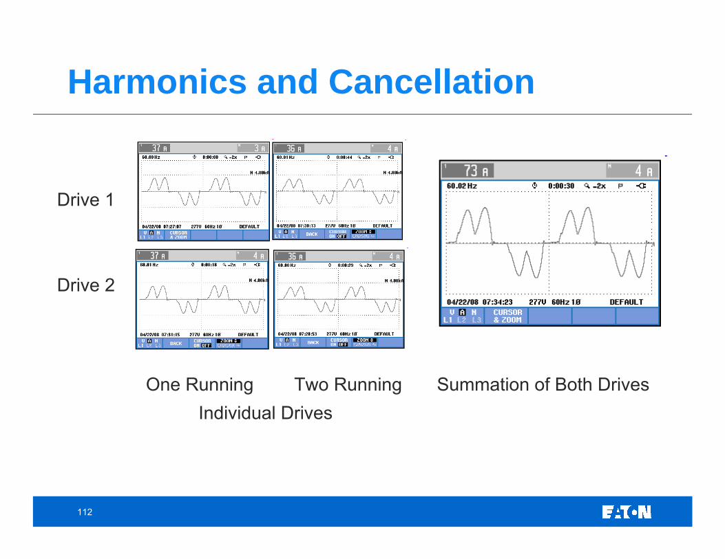
One Running Two Running Summation of Both DrivesIndividual Drives
113
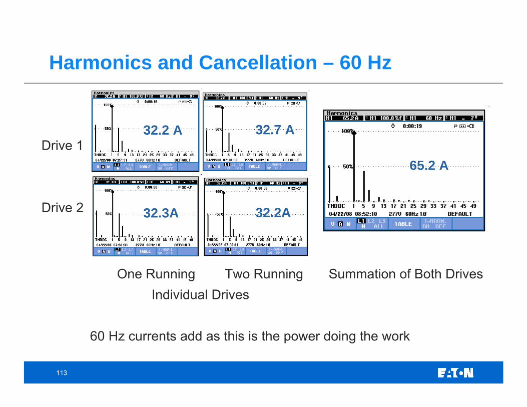
Harmonics and Cancellation – 60 Hz
One Running Two Running Summation of Both DrivesIndividual Drives
60 Hz currents add as this is the power doing the work
Drive 1
Drive 2
32.2 A
32.3A
32.7 A
32.2A
65.2 A
114
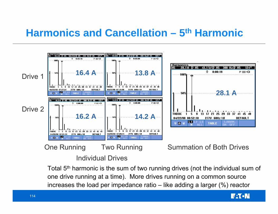
Harmonics and Cancellation – 5th Harmonic
Drive 1
Drive 2
One Running Two Running Summation of Both DrivesIndividual Drives
Total 5th harmonic is the sum of two running drives (not the individual sum of one drive running at a time). More drives running on a common source increases the load per impedance ratio – like adding a larger (%) reactor
16.4 A
16.2 A
13.8 A
14.2 A
28.1 A
115
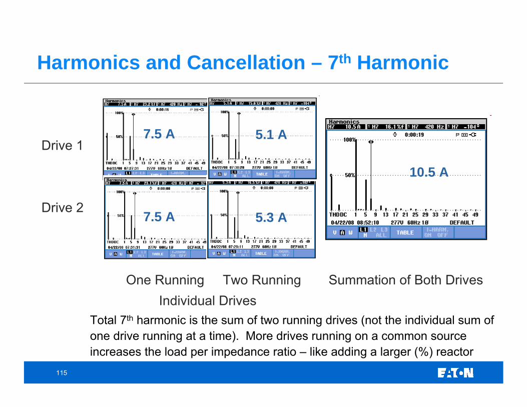
Harmonics and Cancellation – 7th Harmonic
Drive 1
Drive 2
One Running Two Running Summation of Both DrivesIndividual Drives
Total 7th harmonic is the sum of two running drives (not the individual sum of one drive running at a time). More drives running on a common source increases the load per impedance ratio – like adding a larger (%) reactor
7.5 A
7.5 A
5.1 A
5.3 A
10.5 A
116
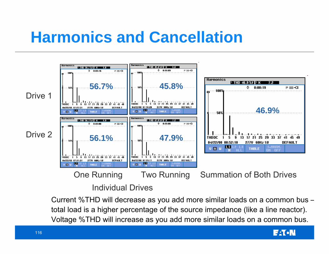
Harmonics and Cancellation
Drive 1
Drive 2
One Running Two Running Summation of Both DrivesIndividual Drives
Current %THD will decrease as you add more similar loads on a common bus –total load is a higher percentage of the source impedance (like a line reactor). Voltage %THD will increase as you add more similar loads on a common bus.
56.7%
56.1%
45.8%
47.9%
46.9%
117
Transformers and Harmonic Currents• Many people incorrectly assume that ALL harmonics are
trapped by delta-wye transformers. The fact is:• only the balanced third harmonics (and multiples of the third)
circulate in the delta winding and are therefore trapped.• other harmonic currents (5th and 7th, for example) and the
unbalanced multiples of the third harmonics can pass through thetransformer
• harmonic currents are inductively coupled along with the 60 Hz current by the ratio of the primary turns to the secondary turns.
• Higher order harmonics (> 25th) may or may not be inductively coupled through the transformer.
• Sometimes, higher frequency harmonics are capacitivelycoupled from secondary to primary (not by the turns ratio).
118
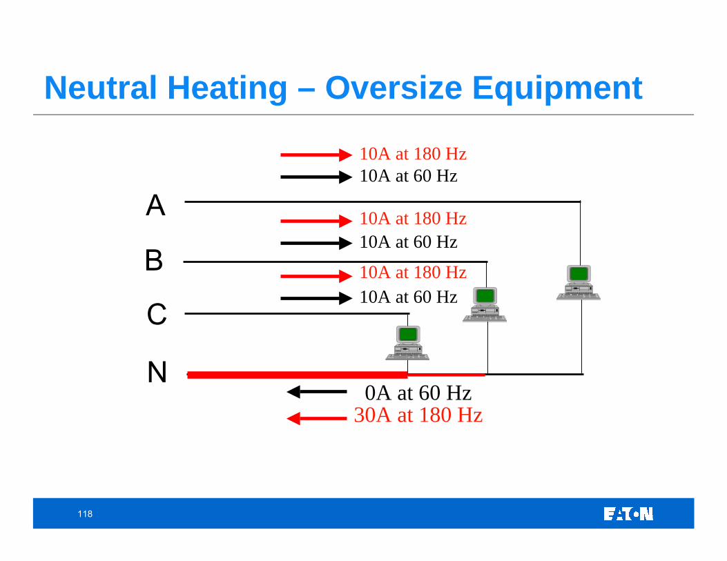
Neutral Heating – Oversize Equipment
C
B
A
N0A at 60 Hz
10A at 60 Hz
10A at 60 Hz
10A at 60 Hz
30A at 180 Hz
10A at 180 Hz
10A at 180 Hz
10A at 180 Hz
119
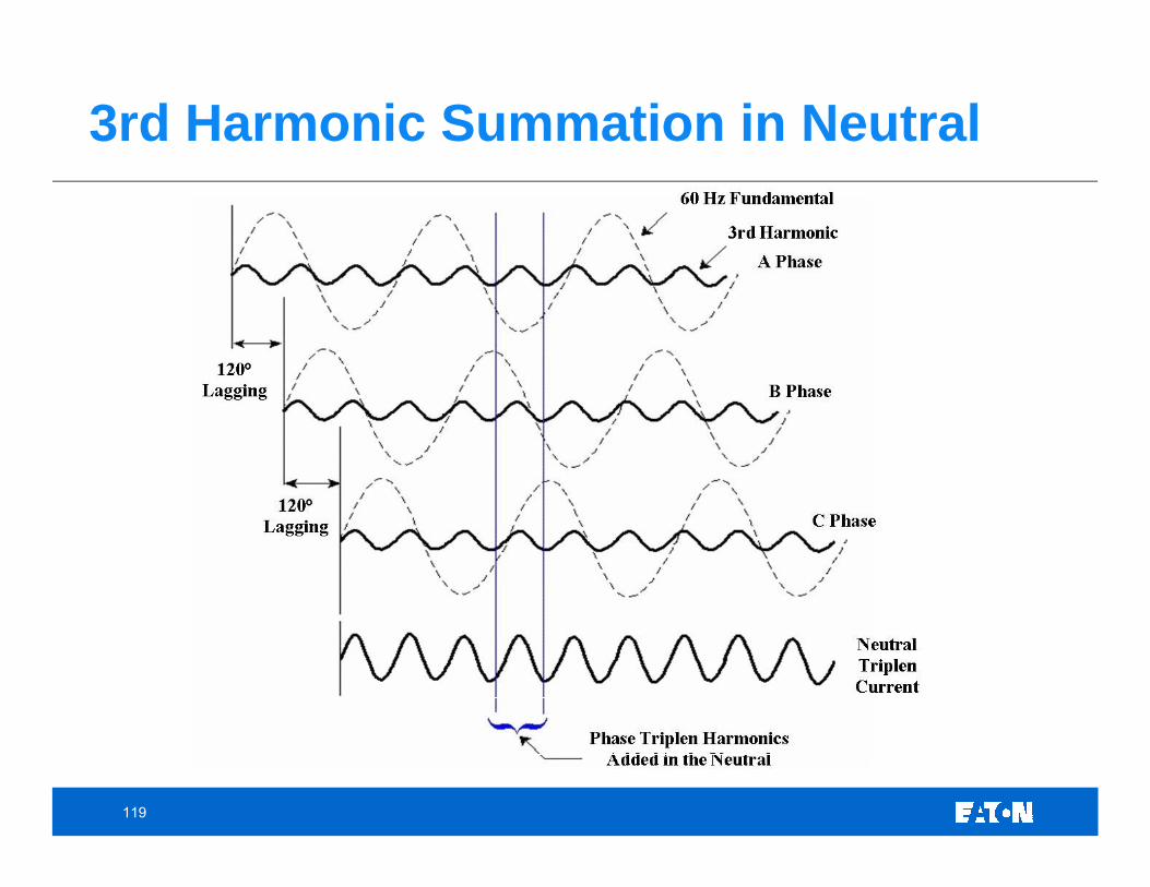
3rd Harmonic Summation in Neutral
120
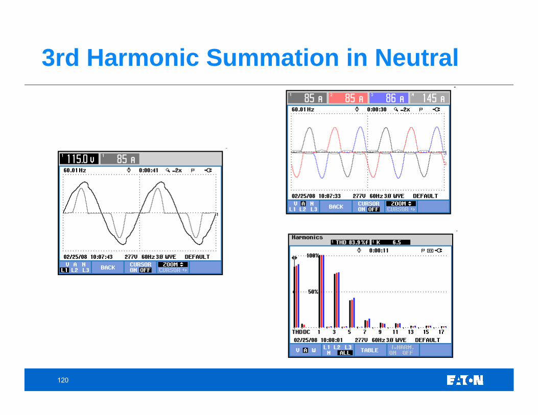
3rd Harmonic Summation in Neutral
121
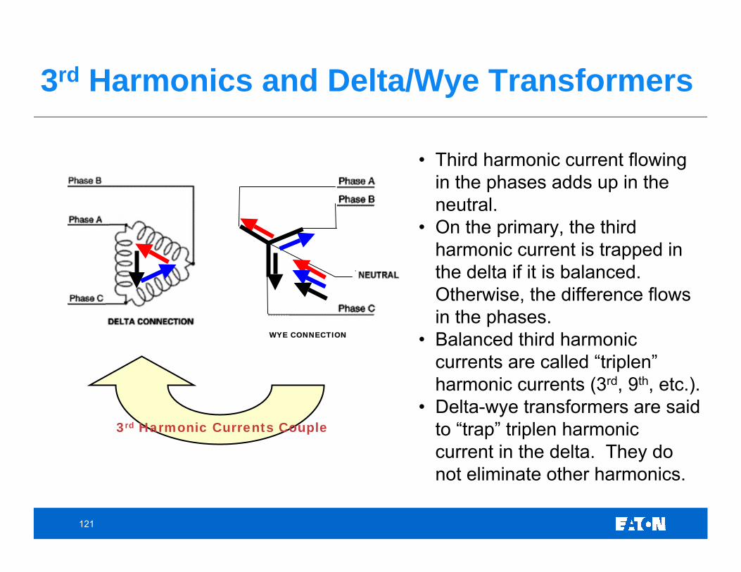
3rd Harmonics and Delta/Wye Transformers
• Third harmonic current flowing in the phases adds up in the neutral.
• On the primary, the third harmonic current is trapped in the delta if it is balanced. Otherwise, the difference flows in the phases.
• Balanced third harmonic currents are called “triplen” harmonic currents (3rd, 9th, etc.).
• Delta-wye transformers are said to “trap” triplen harmonic current in the delta. They do not eliminate other harmonics.
WYE CONNECTION
3rd Harmonic Currents Couple
122
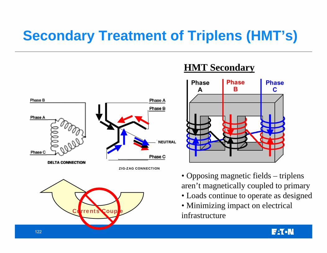
Secondary Treatment of Triplens (HMT’s)
HMT Secondary
• Opposing magnetic fields – triplens aren’t magnetically coupled to primary• Loads continue to operate as designed• Minimizing impact on electrical infrastructure
ZIG-ZAG CONNECTION
Currents Couple
123
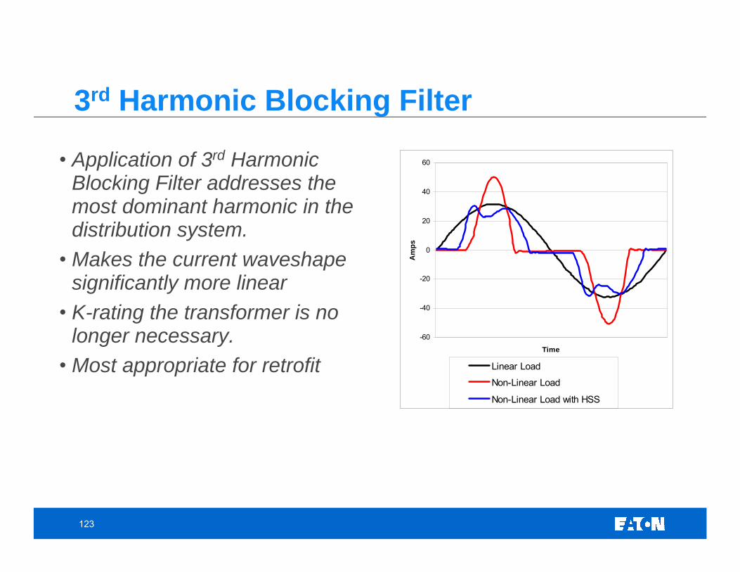
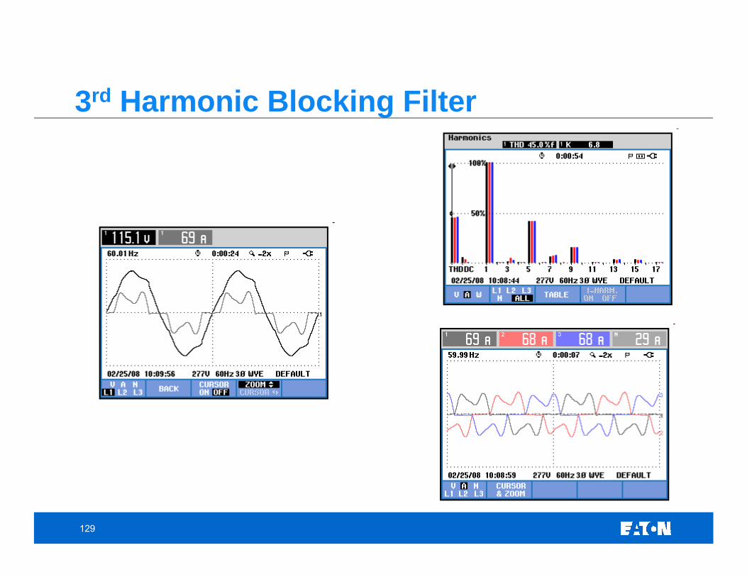
3rd Harmonic Blocking Filter
-60
-40
-20
0
20
40
60
Time
Am
ps
Linear Load
Non-Linear Load
Non-Linear Load with HSS
• Application of 3rd Harmonic Blocking Filter addresses the most dominant harmonic in the distribution system.
• Makes the current waveshapesignificantly more linear
• K-rating the transformer is no longer necessary.
• Most appropriate for retrofit
124
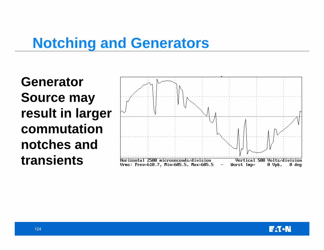
Generator Source may result in larger commutation notches and transients
Notching and Generators
125
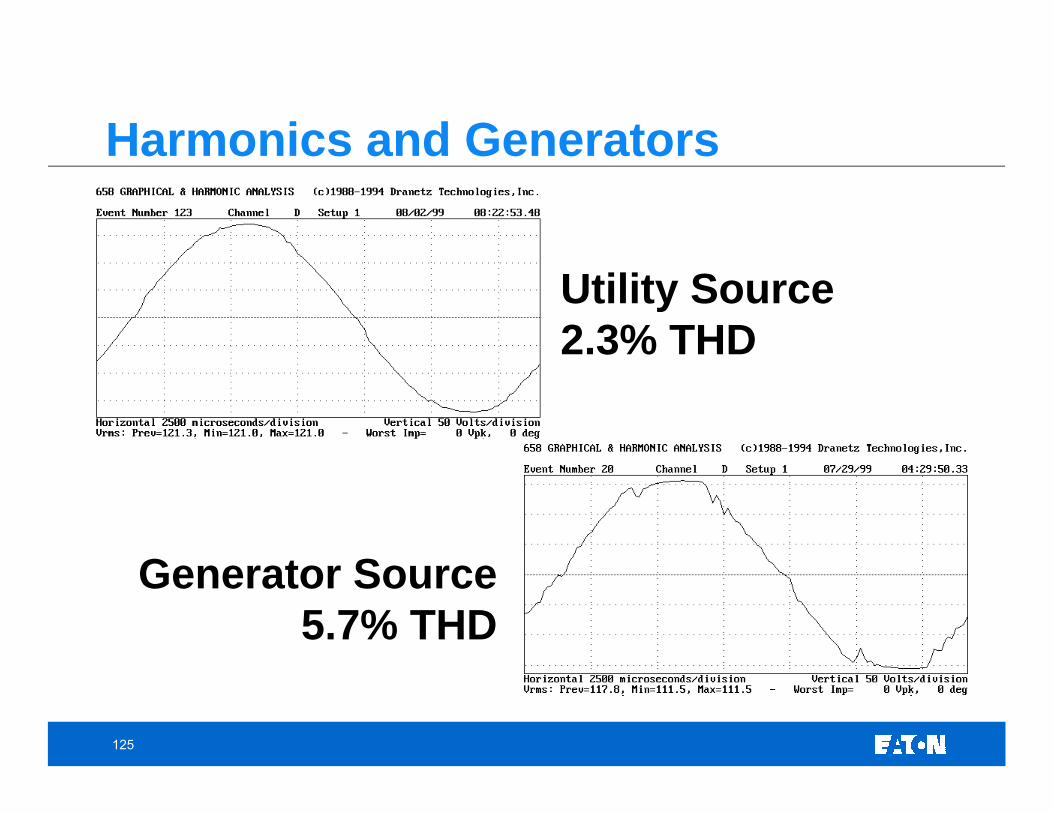
Utility Source2.3% THD
Generator Source 5.7% THD
Harmonics and Generators
126
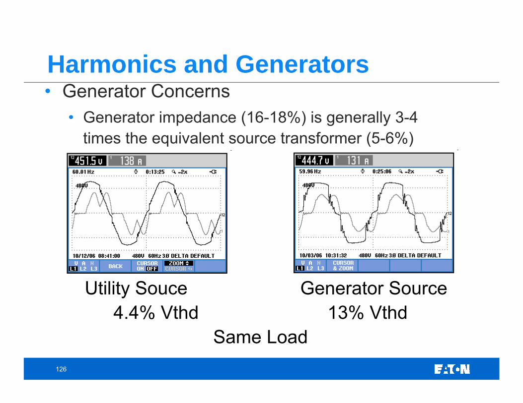
Harmonics and Generators• Generator Concerns
• Generator impedance (16-18%) is generally 3-4 times the equivalent source transformer (5-6%)
Utility Souce Generator Source4.4% Vthd 13% Vthd
Same Load
127
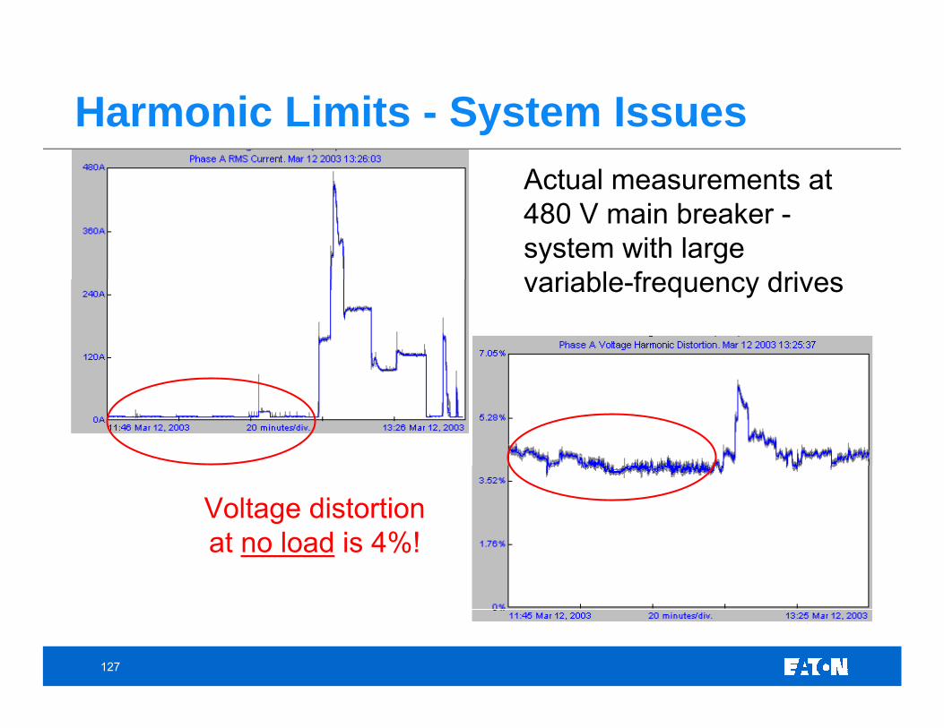
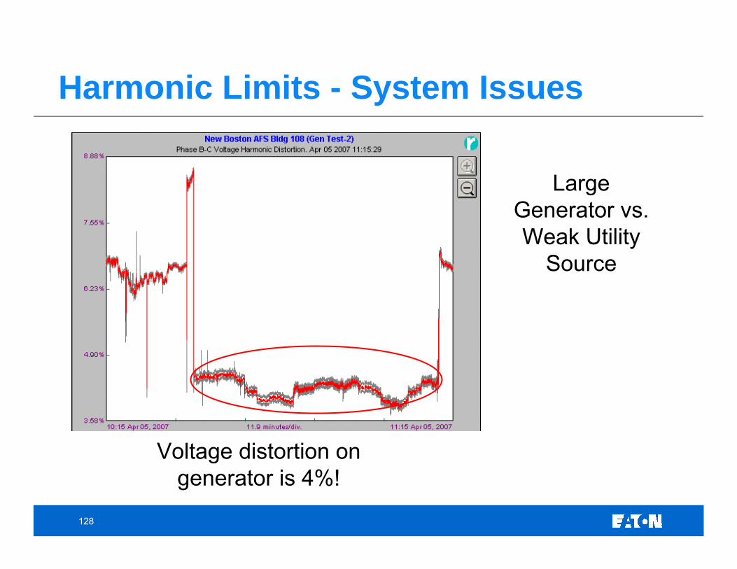
Harmonic Limits - System Issues
Voltage distortion at no load is 4%!
Actual measurements at 480 V main breaker -system with large variable-frequency drives
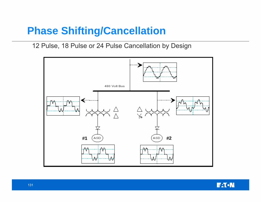
Phase Shifting/Cancellation12 Pulse, 18 Pulse or 24 Pulse Cancellation by Design
#1 #2
132
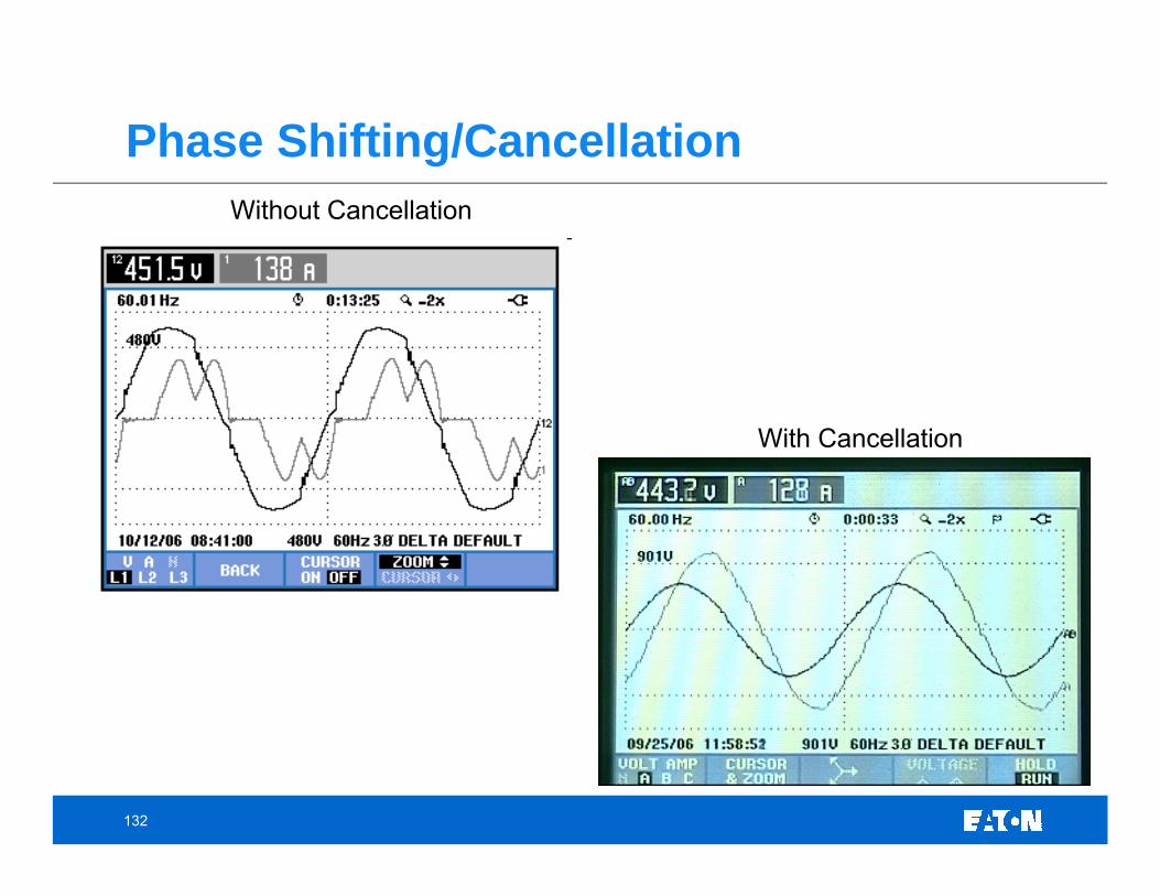
Phase Shifting/CancellationWithout Cancellation
With Cancellation
133
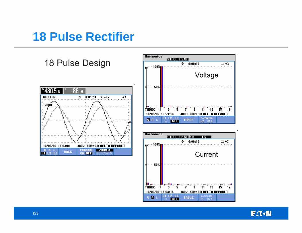
18 Pulse DesignVoltage
Current
18 Pulse Rectifier
134
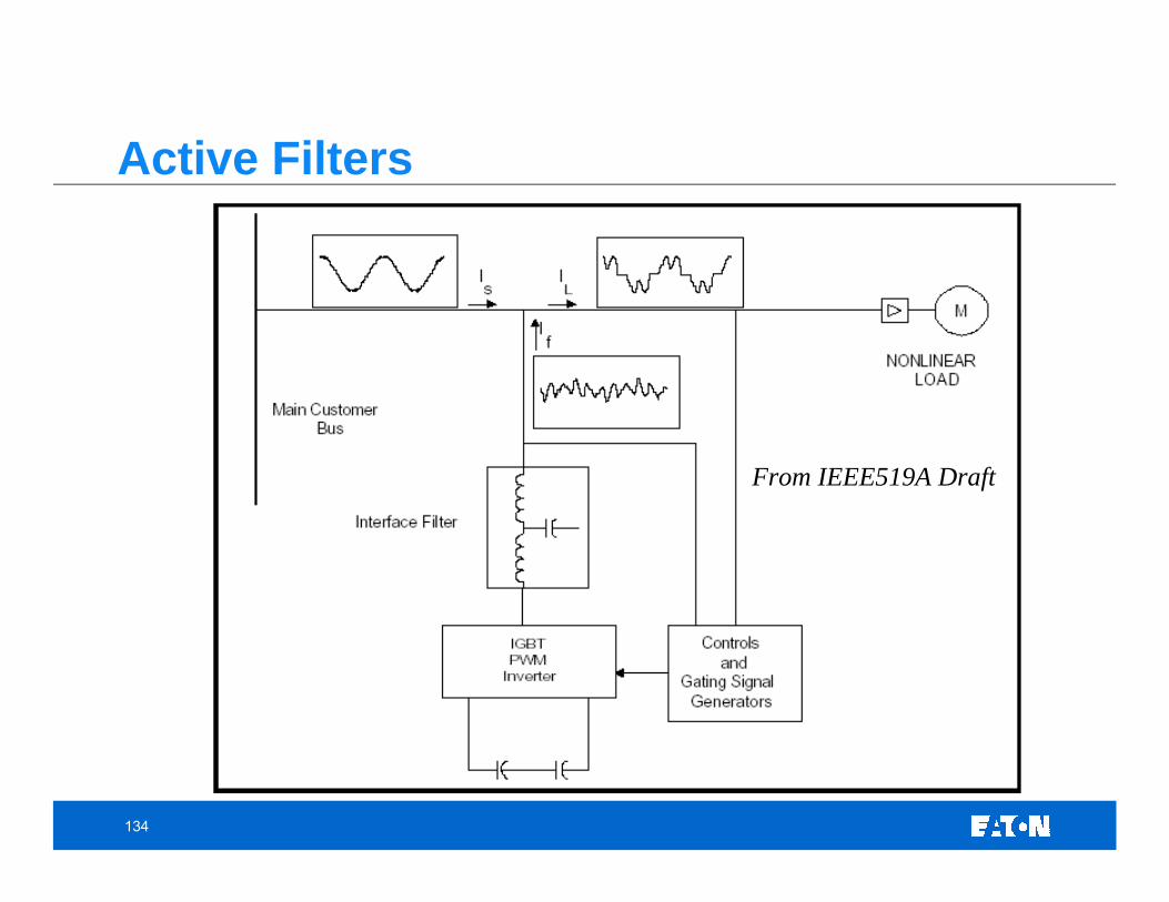
From IEEE519A Draft
Active Filters
135
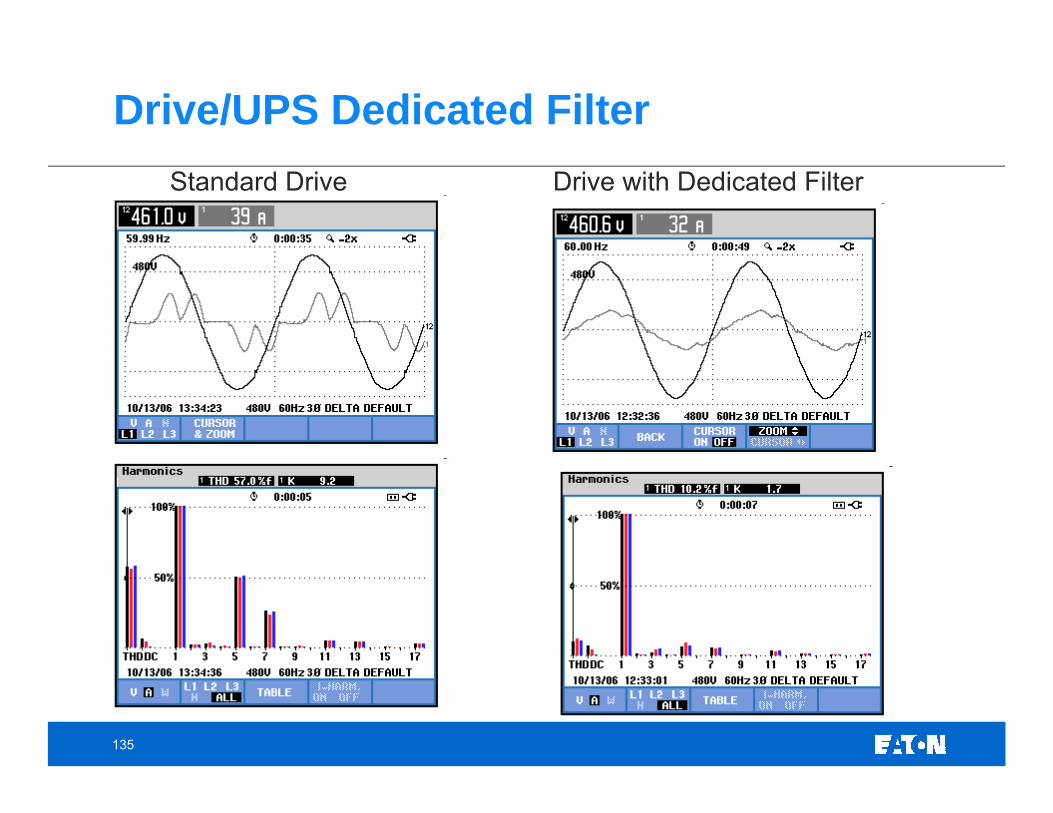
Drive/UPS Dedicated FilterStandard Drive Drive with Dedicated Filter
136
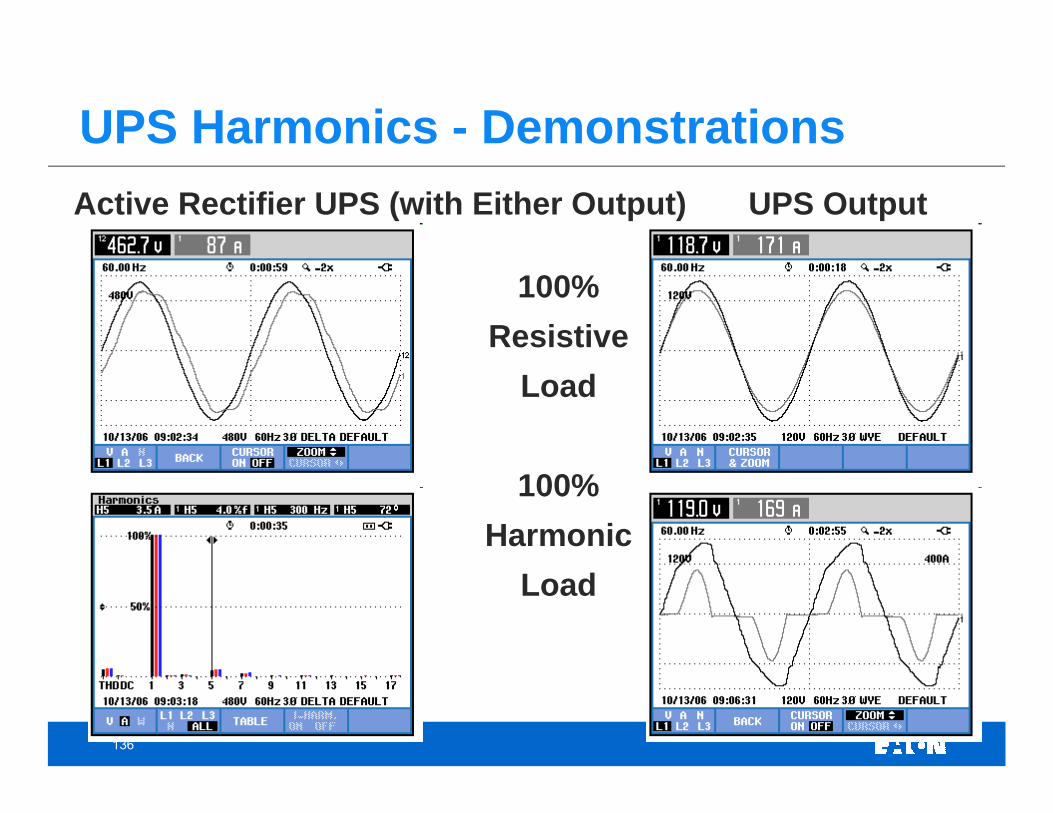
Active Rectifier UPS (with Either Output) UPS Output
100%Resistive
Load
100% Harmonic
Load
UPS Harmonics - Demonstrations
137
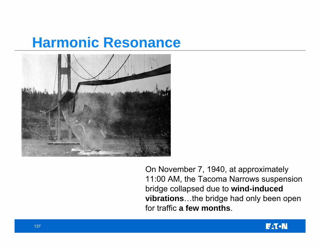
Harmonic Resonance
On November 7, 1940, at approximately 11:00 AM, the Tacoma Narrows suspension bridge collapsed due to wind-induced vibrations…the bridge had only been open for traffic a few months.
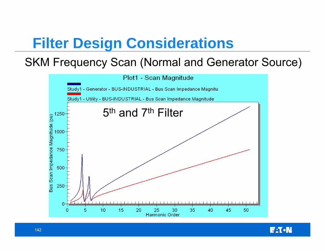
Filter Design ConsiderationsSKM Frequency Scan (Normal and Generator Source)
5th and 7th Filter
143
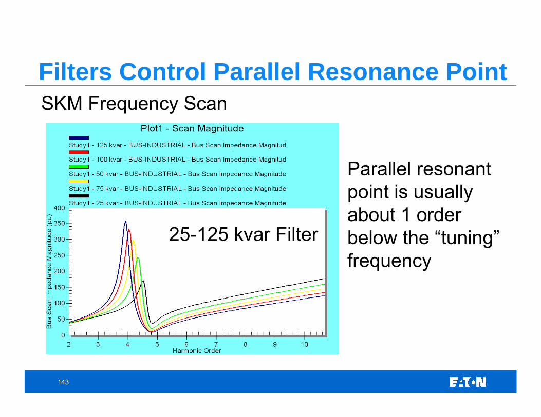
Filters Control Parallel Resonance PointSKM Frequency Scan
25-125 kvar Filter
Parallel resonant point is usually about 1 order below the “tuning” frequency
144
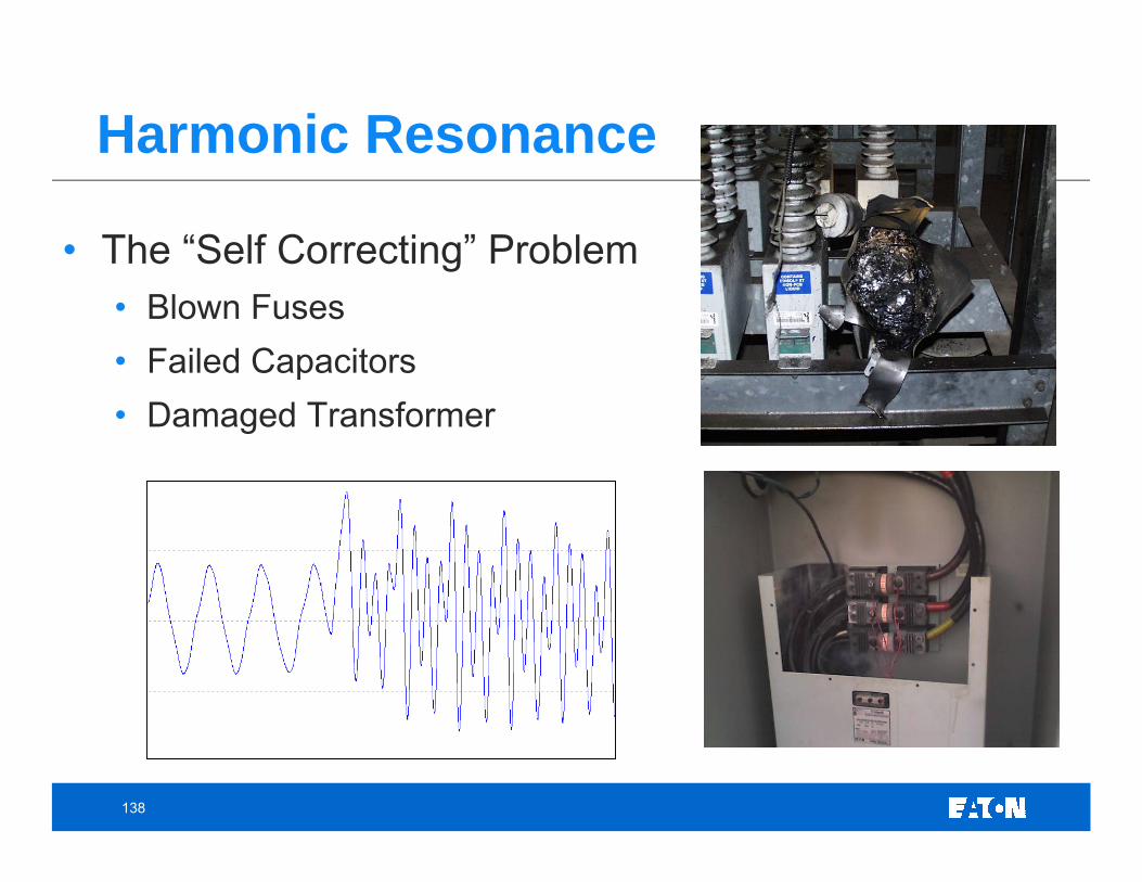
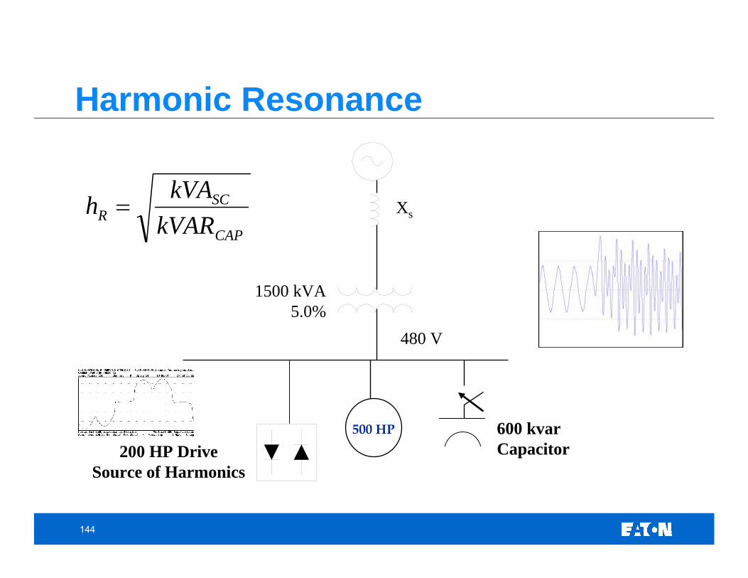
Harmonic Resonance
CAP
SCR kVAR
kVAh =
600 kvarCapacitor
1500 kVA5.0%
480 V
Xs
200 HP DriveSource of Harmonics
500 HP
145
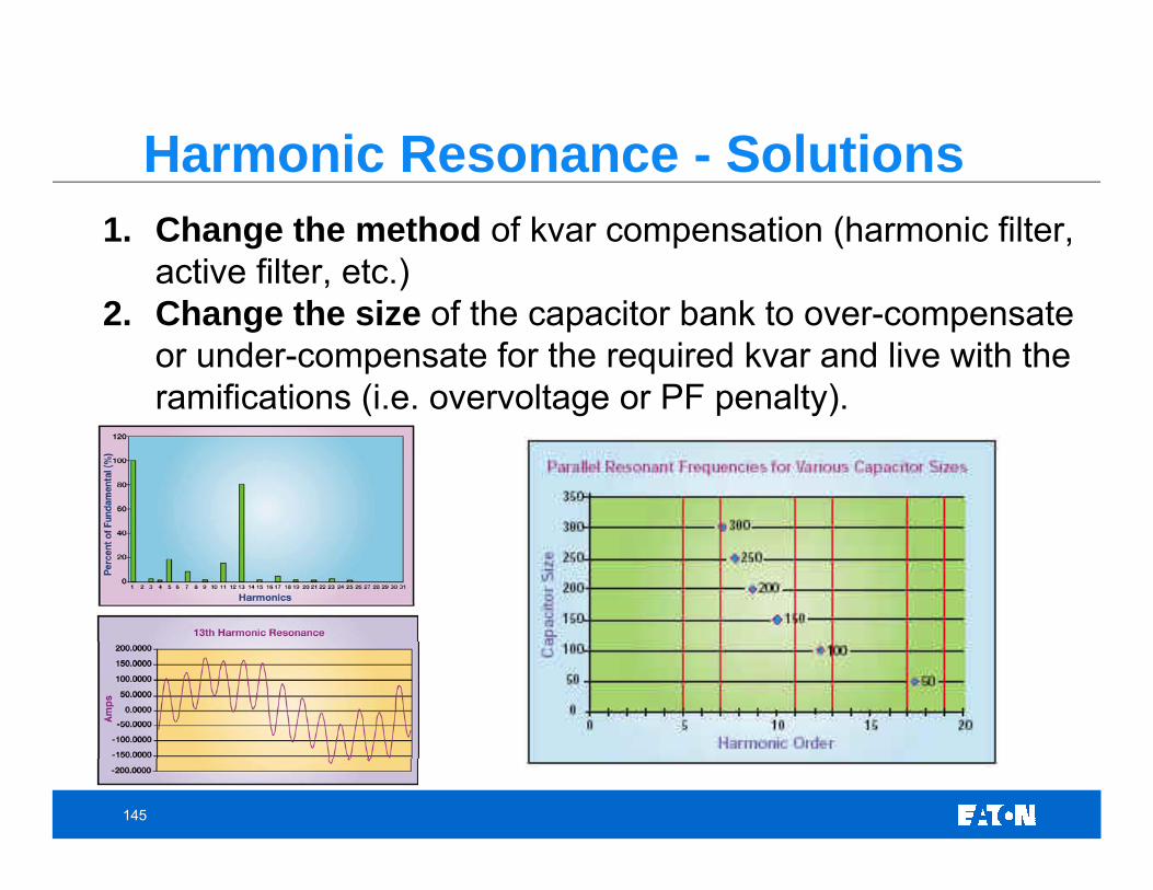
Harmonic Resonance - Solutions1. Change the method of kvar compensation (harmonic filter,
active filter, etc.) 2. Change the size of the capacitor bank to over-compensate
or under-compensate for the required kvar and live with the ramifications (i.e. overvoltage or PF penalty).
146
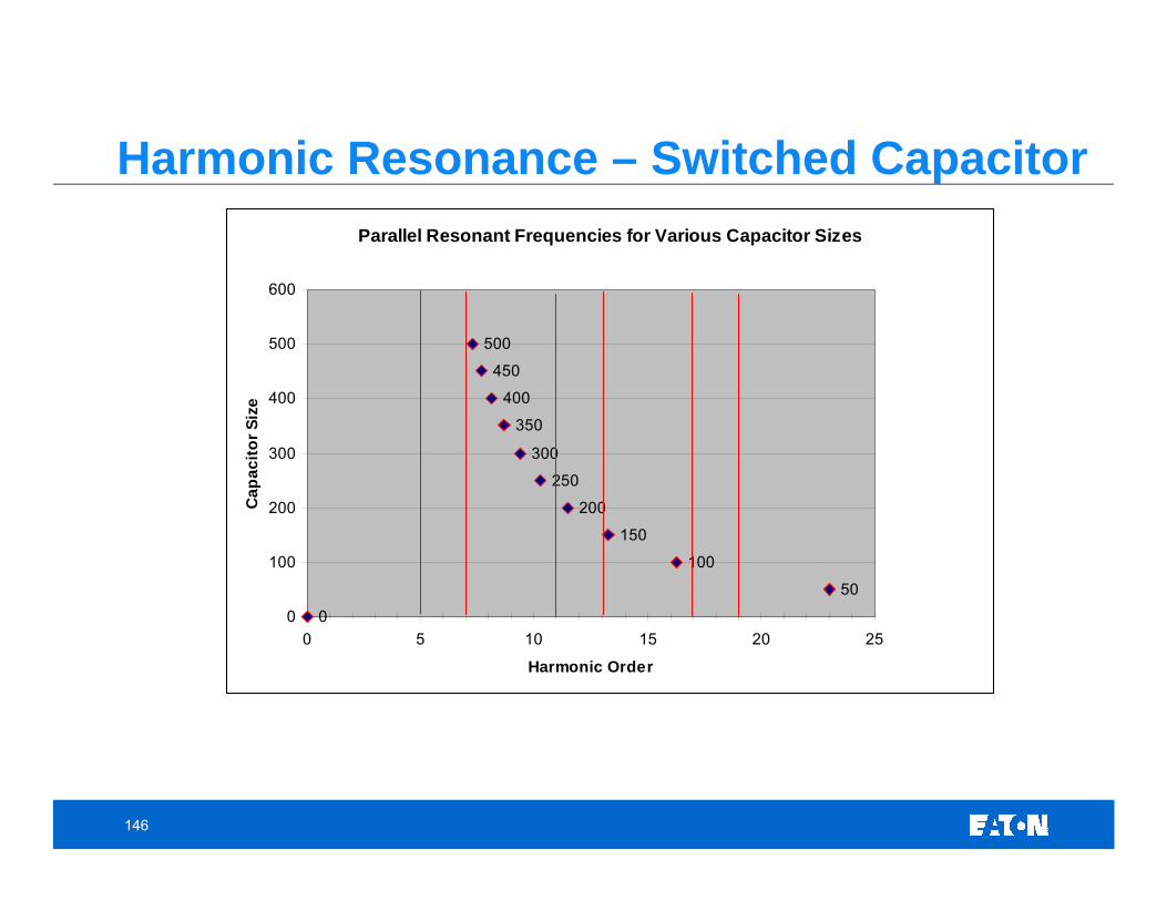
Harmonic Resonance – Switched CapacitorParallel Resonant Frequencies for Various Capacitor Sizes
0
50
100
150
200
250
300
350
400
450
500
0
100
200
300
400
500
600
0 5 10 15 20 25
Harmonic Order
Cap
acito
r Siz
e
147
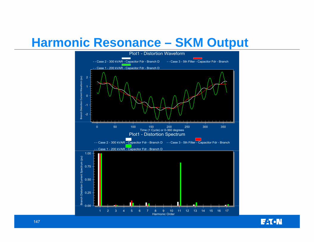
Harmonic Resonance – SKM Output
-2
-1
0
1
2
0 50 100 150 200 250 300 350
Plot1 - Distortion Waveform
Bra
nch
Dis
torti
on C
urre
nt W
avef
orm
(pu)
Time (1 Cycle) or 0-360 degrees
- - Case 2 - 300 kVAR - Capacitor Fdr - Branch D - - Case 3 - 5th Filter - Capacitor Fdr - Branch
- - Case 1 - 200 kVAR - Capacitor Fdr - Branch D
0.00
0.25
0.50
0.75
1.00
1 2 3 4 5 6 7 8 9 10 11 12 13 14 15 16 17
Plot1 - Distortion Spectrum
Bra
nch
Dis
torti
on C
urre
nt S
pect
rum
(pu)
Harmonic Order
- - Case 2 - 300 kVAR - Capacitor Fdr - Branch D - - Case 3 - 5th Filter - Capacitor Fdr - Branch
- - Case 1 - 200 kVAR - Capacitor Fdr - Branch D
148
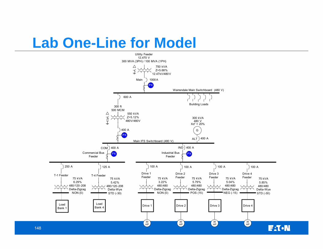
Lab One-Line for Model
600 A
300 ft500 MCM
1000A
Warrendale Main Switchboard (480 V)
Utility Feeder 12,470 V
300 MVA (3PH) / 100 MVA (1PH)
PX
750 kVAZ=5.68%
12.47kV/480V
Building Loads
550 kVAZ=5.12%
480V/480V
400 A
PX
400 A 400 A
Commercial Bus Feeder
PXPX Industrial Bus Feeder
400 AMain IFS Switchboard (480 V)
Main
ALT
INDCOM
G
300 kVA
Xd” = 20%480 V
100 A
Drive 1Feeder 75 kVA
5.79%480 /480
Delta-ZigzagPOS (15)
100 A
Drive 2Feeder 75 kVA
5.04%480 /480
Delta-ZigzagNEG (-15)
100 A
Drive 3Feeder 75 kVA
5.85%480/480
Delta-WyeSTD (-30)
100 A
Drive 4Feeder75 kVA
3.22%480 /480
Delta-ZigzagNON (0)
250 A
T-1 Feeder75 kVA6.29%
480/120-208Delta-Zigzag
NON (0)
125 A
T-4 Feeder75 kVA5.42%
480/120-208Delta-WyeSTD (-30)
Drive 2
30 HP
Drive 3
30 HP
Drive 4
30 HP
Drive 1
30 HP
Load Bank 1
Load Bank 4
149
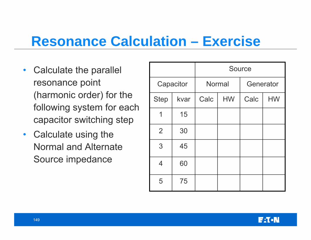
Resonance Calculation – Exercise
• Calculate the parallel resonance point (harmonic order) for the following system for each capacitor switching step
• Calculate using the Normal and Alternate Source impedance
Source
GeneratorNormalCapacitor
755
604
453
302
151
HWCalcHWCalckvarStep
150
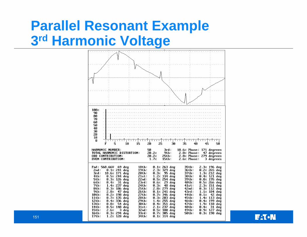
Parallel Resonant Example3rd Harmonic Voltage
151
Parallel Resonant Example3rd Harmonic Voltage
152
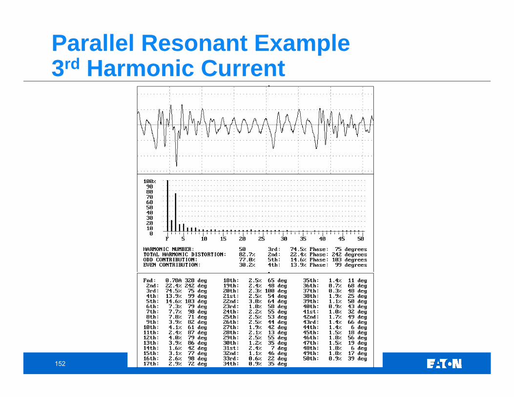
Parallel Resonant Example3rd Harmonic Current
153
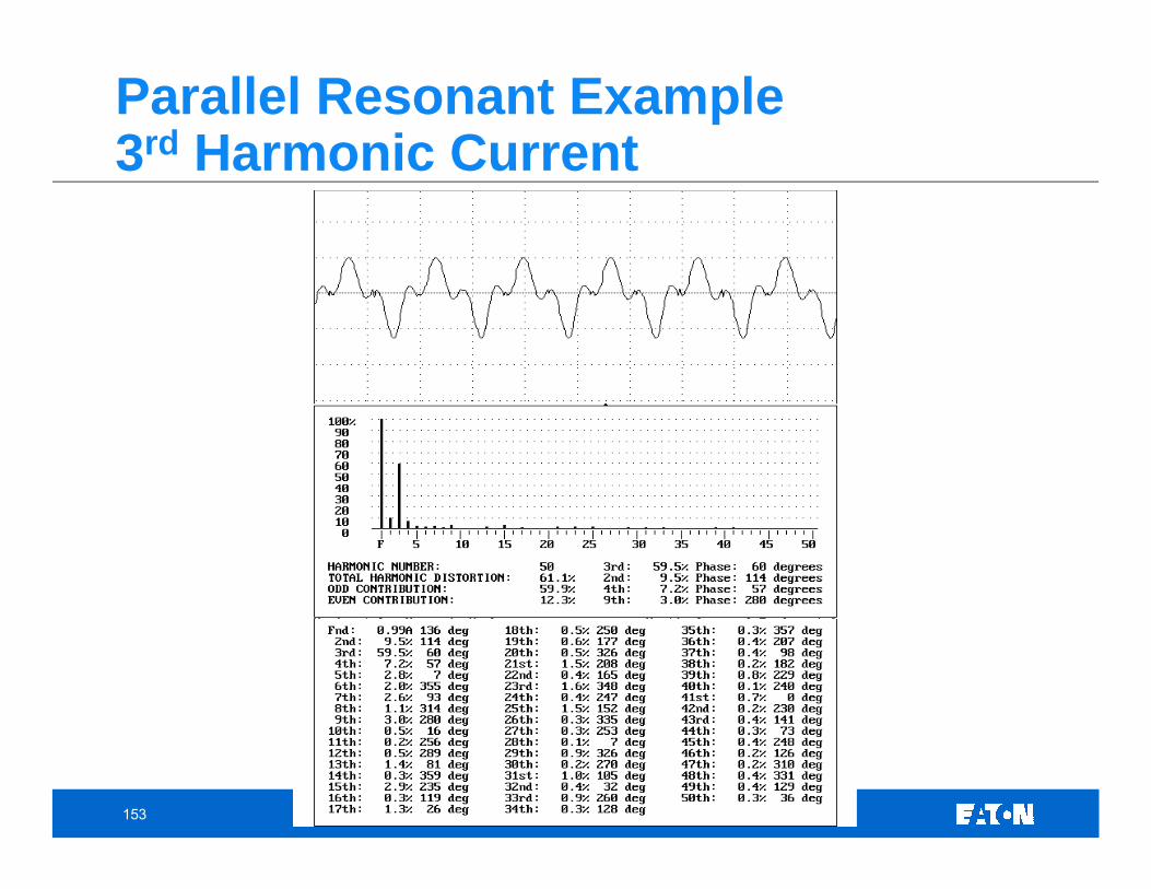
Parallel Resonant Example3rd Harmonic Current
154
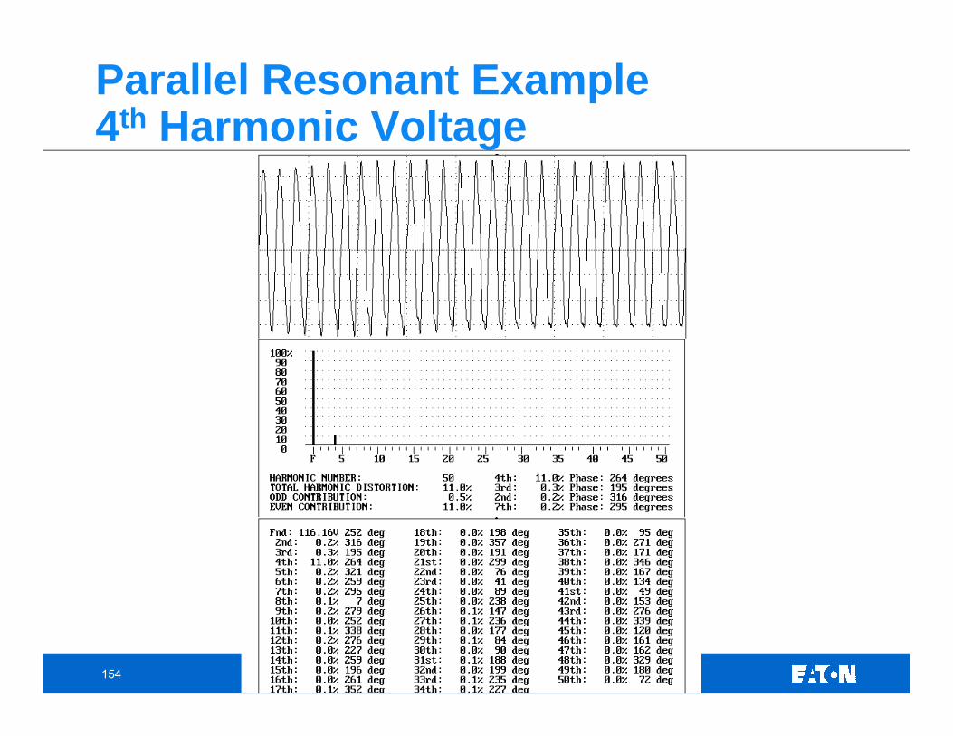
Parallel Resonant Example4th Harmonic Voltage
155
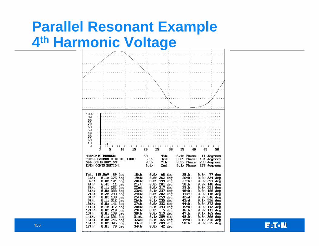
Parallel Resonant Example4th Harmonic Voltage
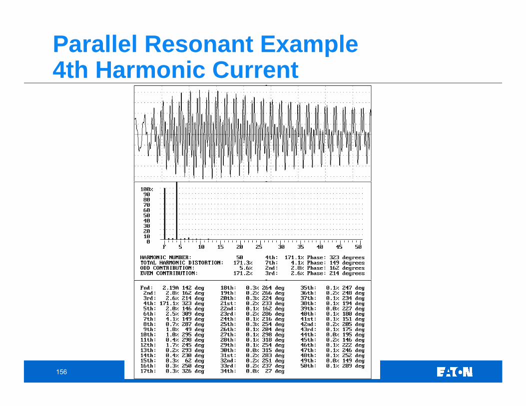
156
Parallel Resonant Example4th Harmonic Current
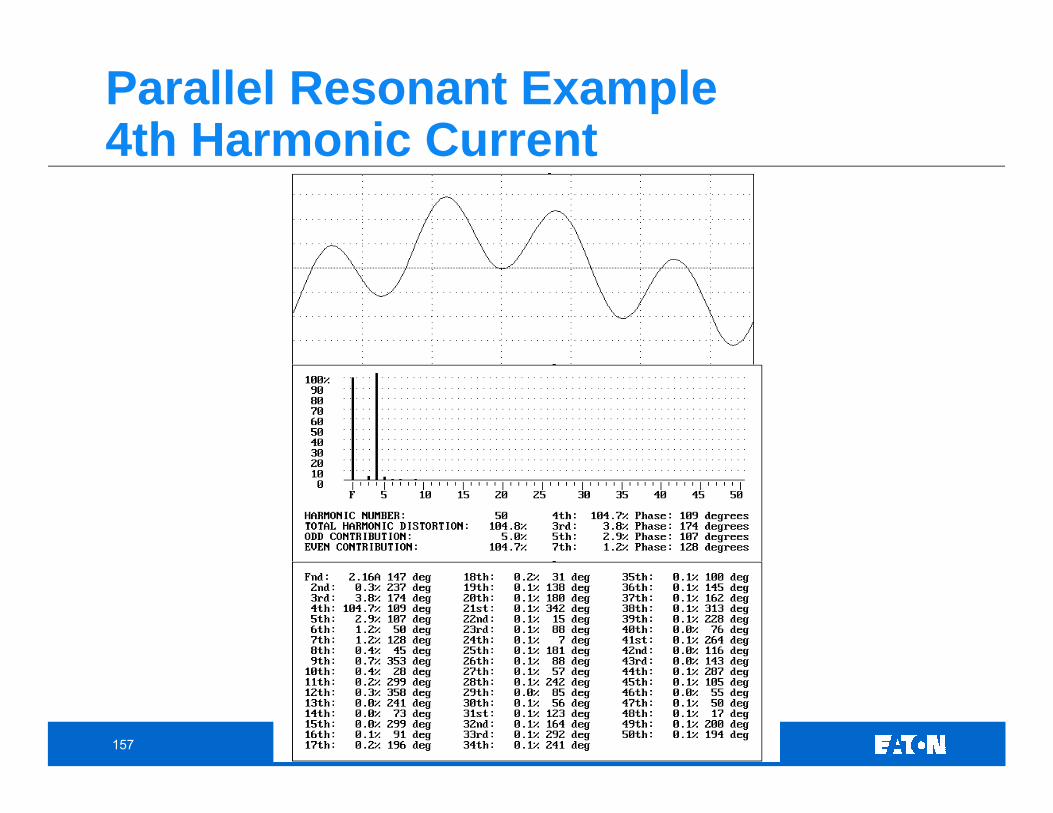
157
Parallel Resonant Example4th Harmonic Current
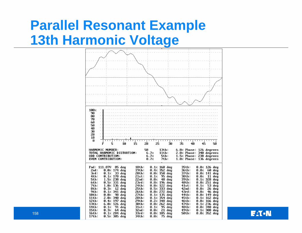
158
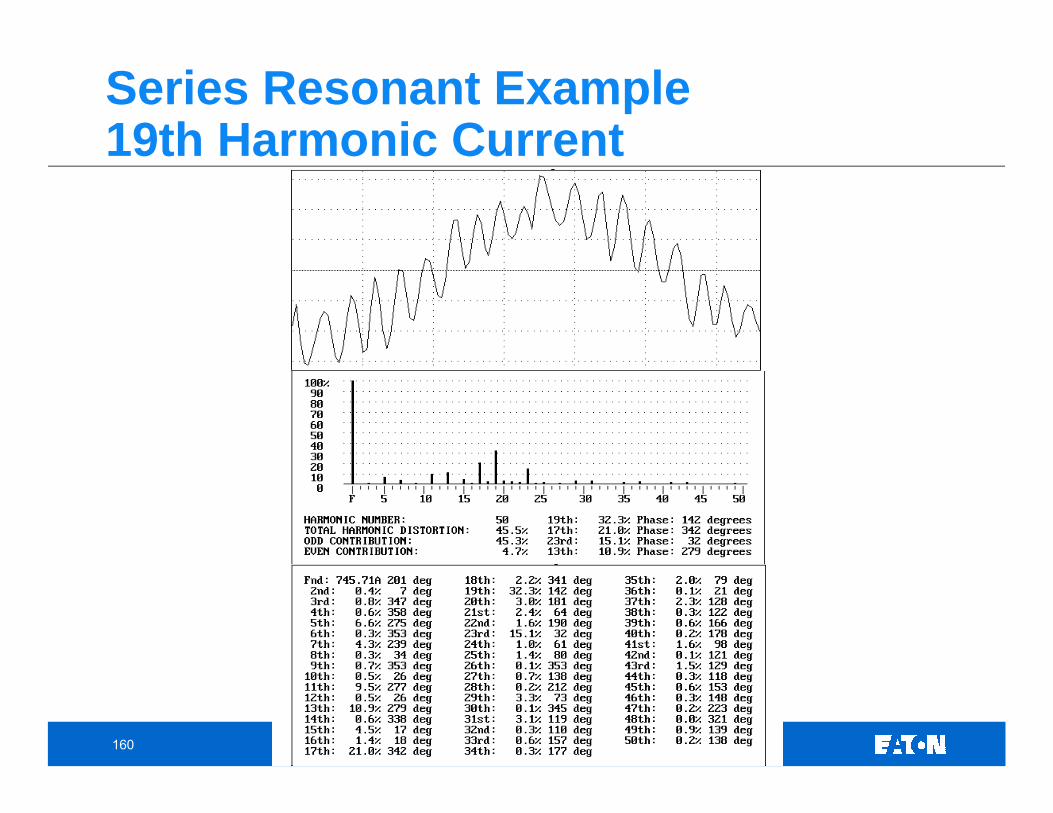
Parallel Resonant Example13th Harmonic Voltage
159
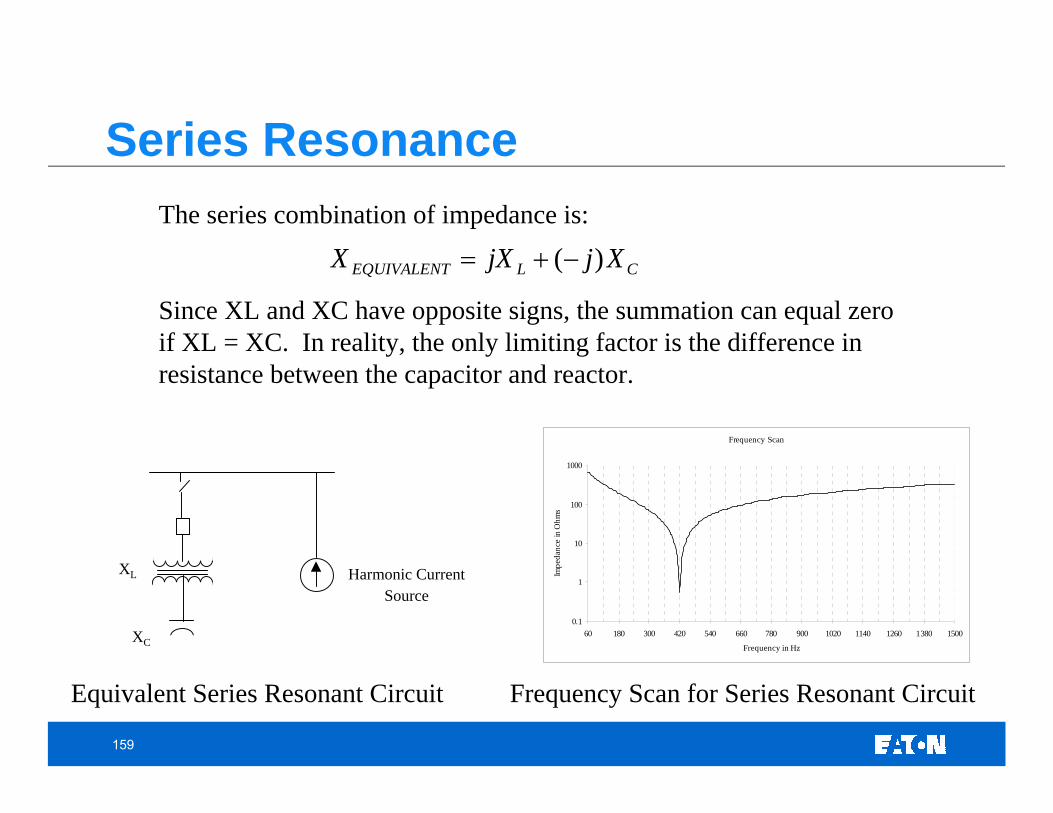
The series combination of impedance is:
Since XL and XC have opposite signs, the summation can equal zero if XL = XC. In reality, the only limiting factor is the difference in resistance between the capacitor and reactor.
Equivalent Series Resonant Circuit Frequency Scan for Series Resonant Circuit
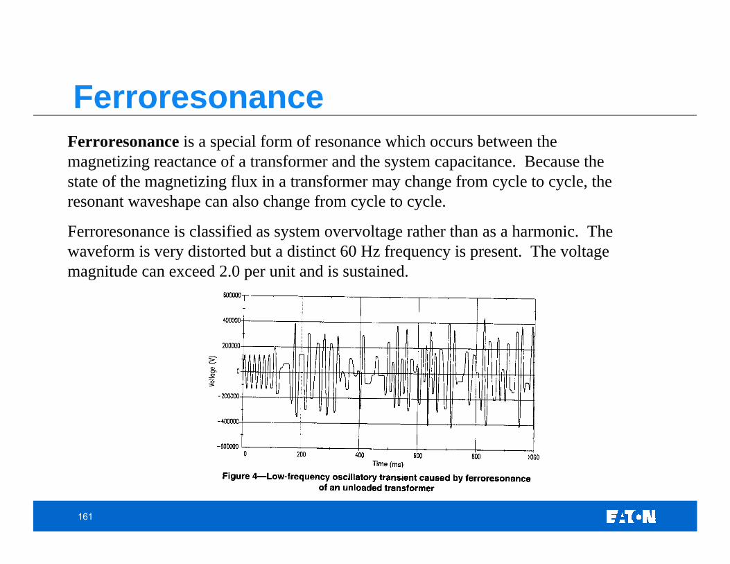
Ferroresonance is a special form of resonance which occurs between the magnetizing reactance of a transformer and the system capacitance. Because the state of the magnetizing flux in a transformer may change from cycle to cycle, the resonant waveshape can also change from cycle to cycle.
Ferroresonance is classified as system overvoltage rather than as a harmonic. The waveform is very distorted but a distinct 60 Hz frequency is present. The voltage magnitude can exceed 2.0 per unit and is sustained.
Ferroresonance
162
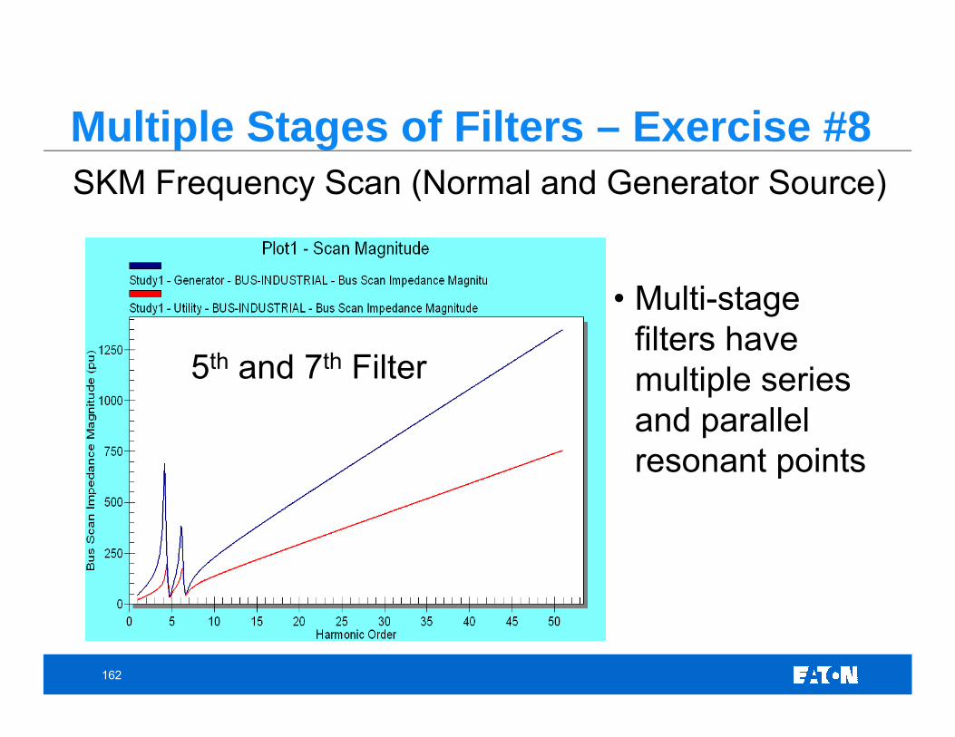
Multiple Stages of Filters – Exercise #8SKM Frequency Scan (Normal and Generator Source)
5th and 7th Filter
• Multi-stage filters have multiple series and parallel resonant points
163
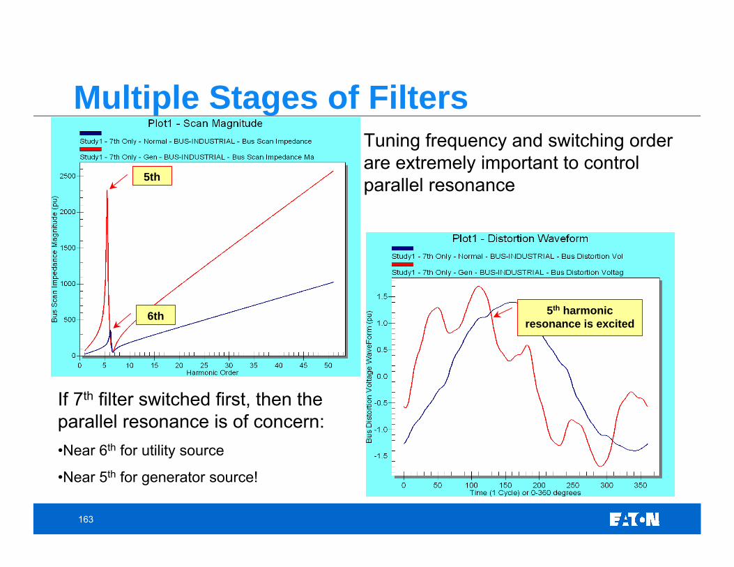
Multiple Stages of FiltersTuning frequency and switching order are extremely important to control parallel resonance5th
6th 5th harmonic resonance is excited
If 7th filter switched first, then the parallel resonance is of concern:•Near 6th for utility source
•Near 5th for generator source!
164
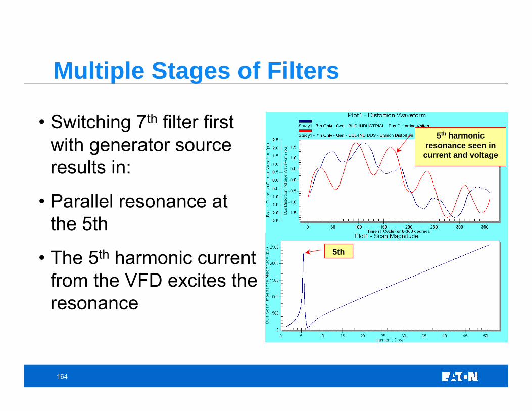
Multiple Stages of Filters
• Switching 7th filter first with generator source results in:
• Parallel resonance at the 5th
• The 5th harmonic current from the VFD excites the resonance
5th
5th harmonic resonance seen in
current and voltage
165
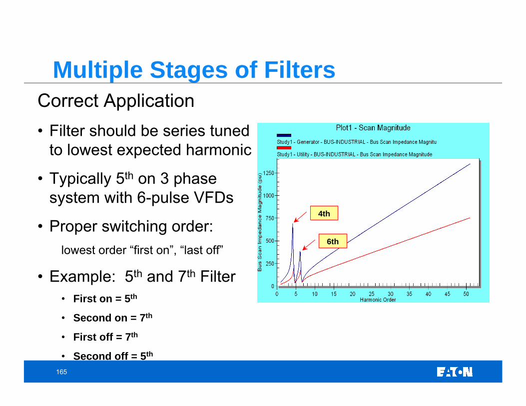
Multiple Stages of FiltersCorrect Application• Filter should be series tuned
to lowest expected harmonic
• Typically 5th on 3 phase system with 6-pulse VFDs
• Proper switching order:lowest order “first on”, “last off”
• Example: 5th and 7th Filter• First on = 5th
• Second on = 7th
• First off = 7th
• Second off = 5th
4th
6th
166
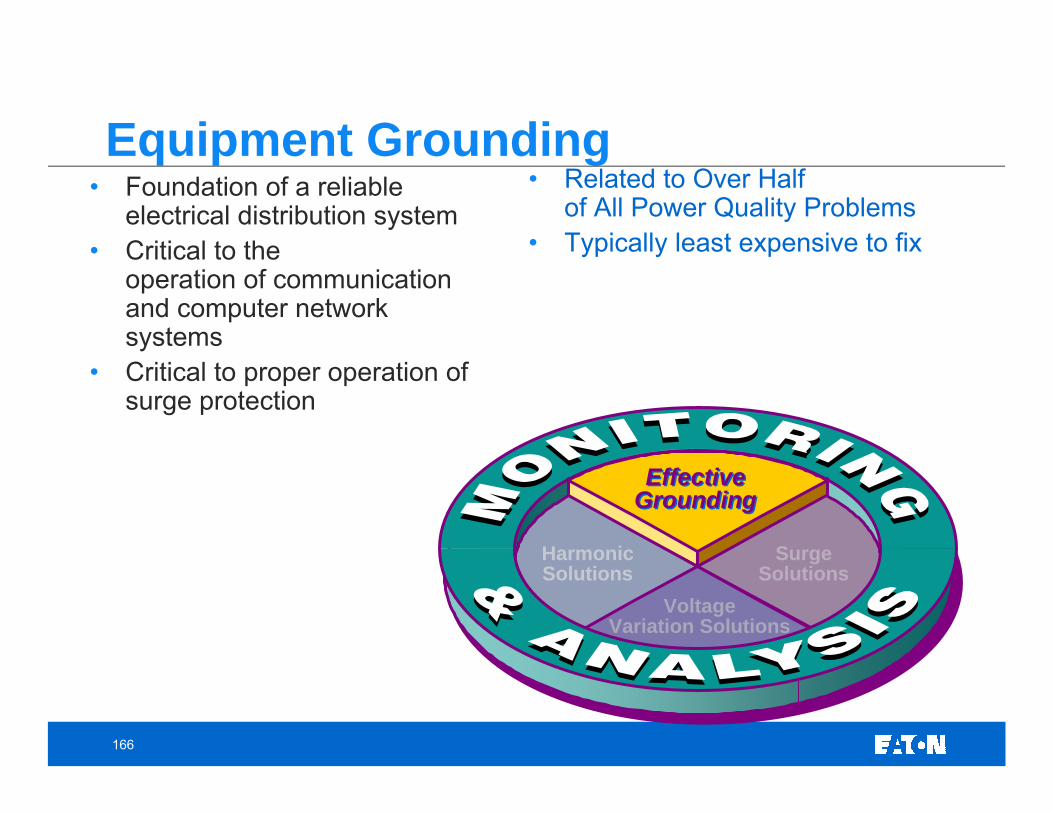
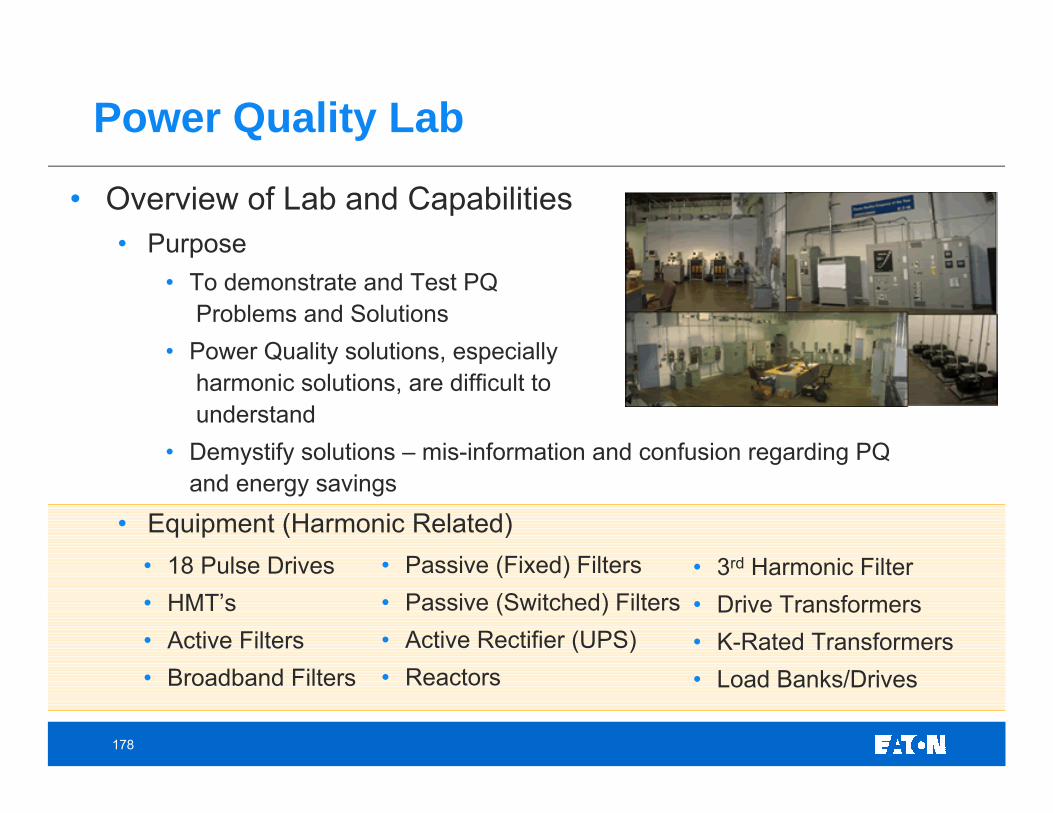
Equipment Grounding• Foundation of a reliable
electrical distribution system• Critical to the
operation of communication and computer network systems
• Critical to proper operation of surge protection
• Related to Over Half of All Power Quality Problems
• Typically least expensive to fix
EffectiveGroundingEffective
Grounding
SurgeSolutions
HarmonicSolutions
VoltageVariation Solutions
167
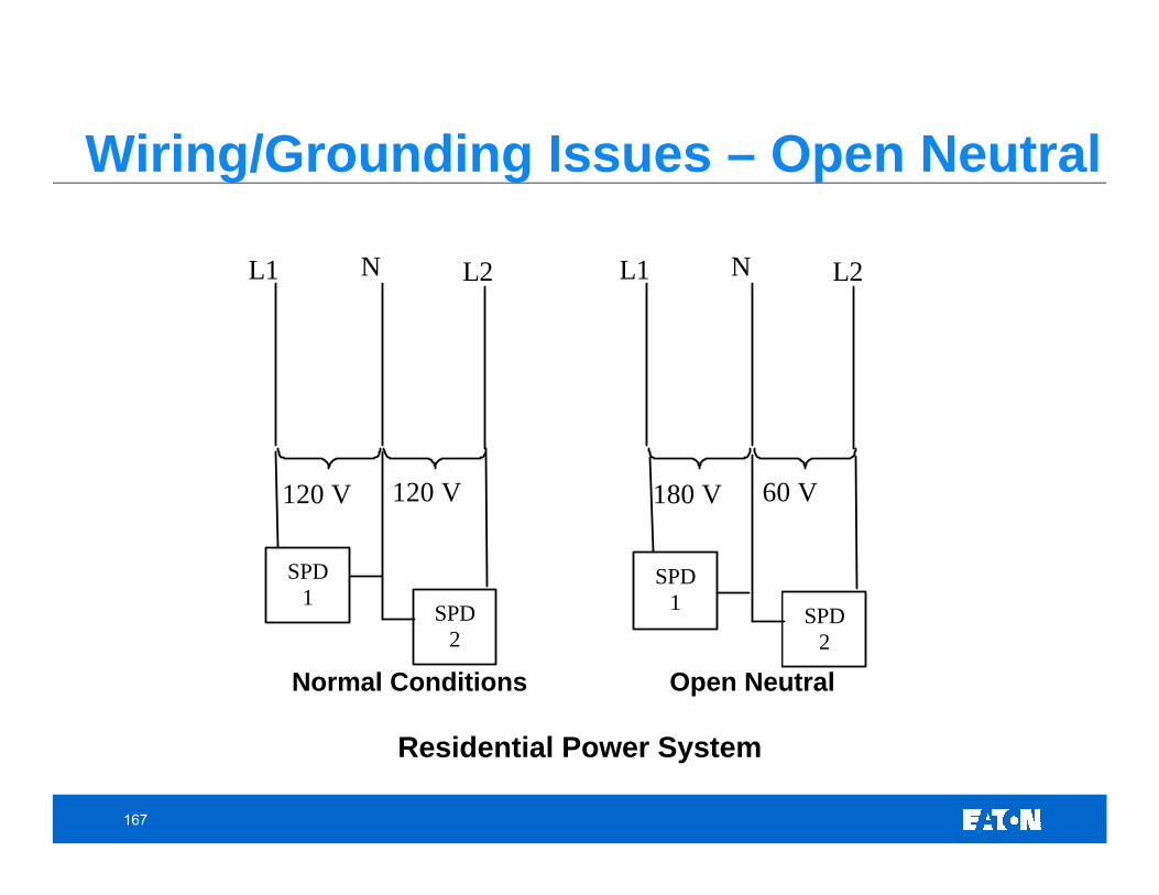
Wiring/Grounding Issues – Open Neutral
120 V 120 V
L1 N L2
180 V 60 V
L1 N L2
SPD1
SPD1 SPD
2 SPD
2
Normal Conditions Open Neutral
Residential Power System
168
When a fault occurs on a distribution system, a sag (retained voltage is zero at the point of fault) will generally occur on all of the phases that are faulted unless a phase shifting transformer –delta/wye or wye/delta – is between the faulted section of the system and the common bus. A swell may occur on the unfaulted phases if the system is not solidly grounded.
If a line-to-ground fault occurs on an ungrounded or high resistance grounded system, the unfaultedphase(s) may experience line-to-line voltage to ground. The line-to-line voltages will maintain the proper relationship for a single-line-to-ground fault.
A
C
B
B’
C’
NGND
N’A’
Faulted
Unfaulted
Faults on Ungrounded System
169
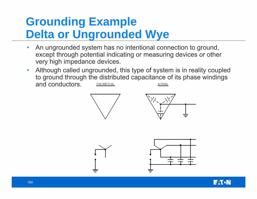
Grounding ExampleDelta or Ungrounded Wye• An ungrounded system has no intentional connection to ground,
except through potential indicating or measuring devices or other very high impedance devices.
• Although called ungrounded, this type of system is in reality coupled to ground through the distributed capacitance of its phase windings and conductors.
170
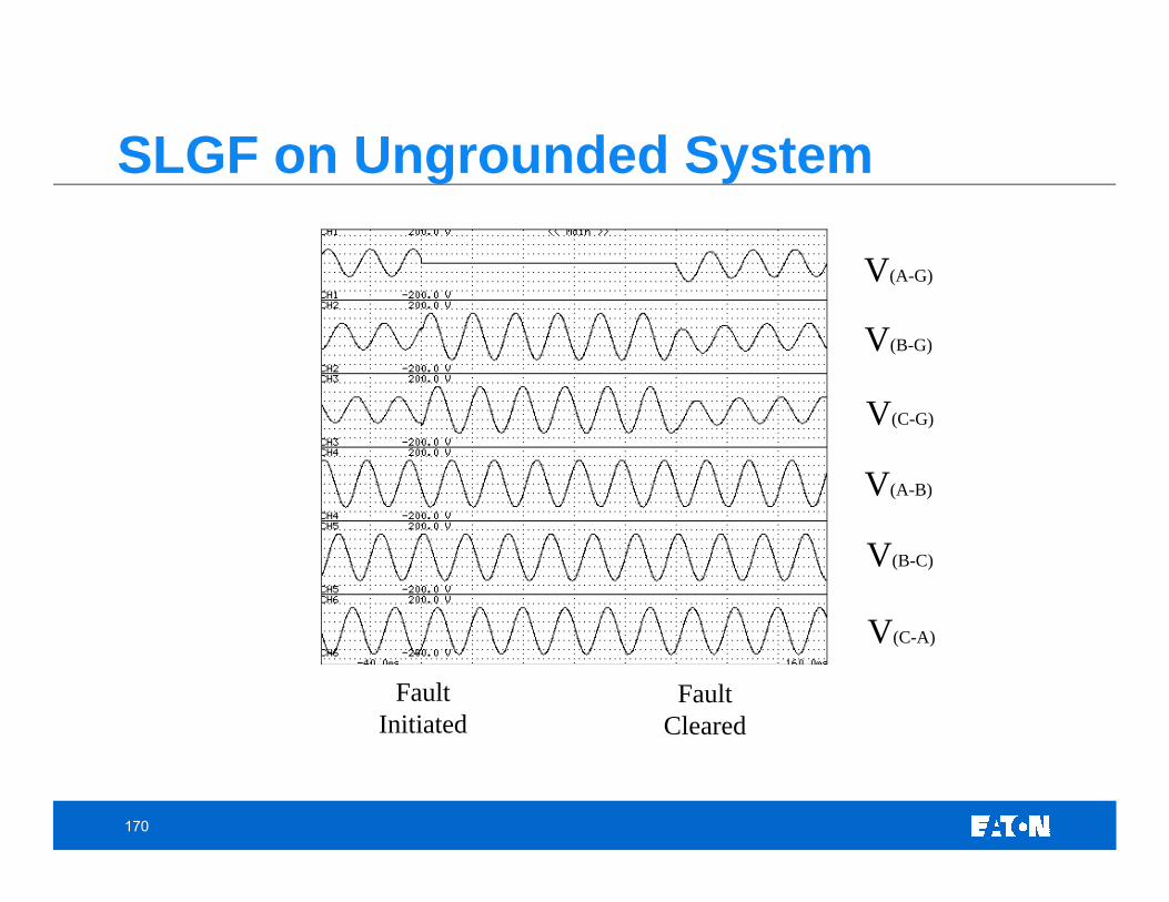
Fault Initiated
Fault Cleared
V(A-G)
V(B-G)
V(C-G)
V(A-B)
V(B-C)
V(C-A)
SLGF on Ungrounded System
171
Transformer Winding ConnectionRelationship of Transformer Connection to Utilization Bus Voltage
When phase shifting transformers (delta/wye, wye/delta, etc.) are electrically located between the faulted part of the system and the monitoring location (the utilization bus), single-line-to-ground fault may be measured as a single-phase, two-phase, or three-phase voltage sag at the utilization bus. For example, a very severe single-line-to-ground fault on a 115 kV transmission system may appear as an insignificant two or three-phase sag on a 120 V outlet in an office building.
Consequently, although the most common faults (>80%) on a power system are single-line-to-ground faults, typical power quality monitoring shows that voltage sags are evenly split between single-phase, two-phase, and three-phase events. This is primarily the result of the effect of phase shifting transformers. Therefore, these transformers may be carefully applied to protect sensitive electronic equipment in some cases.
172
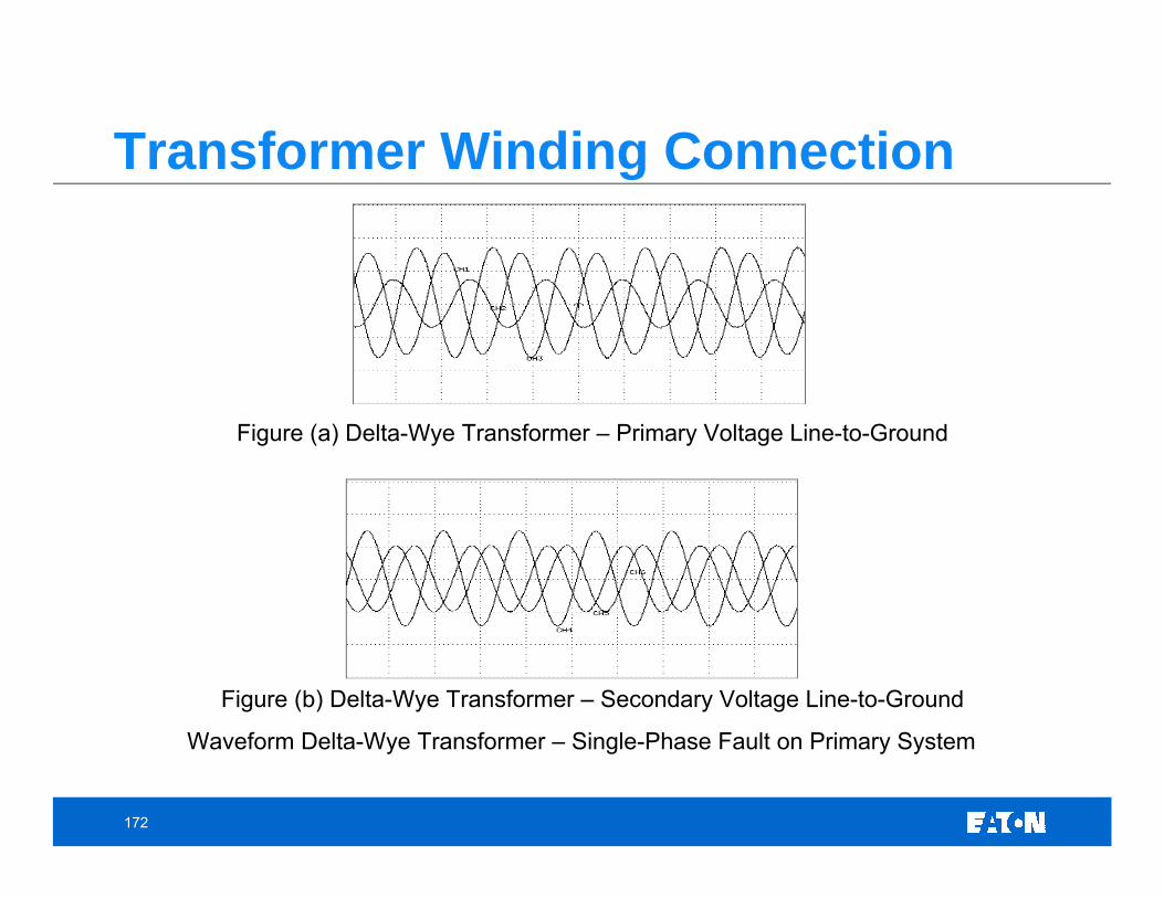
Transformer Winding Connection
Figure (b) Delta-Wye Transformer – Secondary Voltage Line-to-Ground
Waveform Delta-Wye Transformer – Single-Phase Fault on Primary System
Figure (a) Delta-Wye Transformer – Primary Voltage Line-to-Ground
173
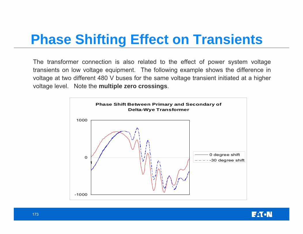
Phase Shifting Effect on TransientsThe transformer connection is also related to the effect of power system voltage transients on low voltage equipment. The following example shows the difference in voltage at two different 480 V buses for the same voltage transient initiated at a higher voltage level. Note the multiple zero crossings.
Phase Shift Between Primary and Secondary of Delta-Wye Transformer
-1000
0
1000
1
0 degree shift-30 degree shift
174
Monitoring on Open Delta PT’s• Normally, on medium voltage power systems, if a voltage measurement is required:
• standard potential transformers are connected to the primary system (i.e. at 13.2 kV, for example) and they are either connected in a Wye configuration or in an Open-Delta configuration.
• The arrangement of the PT’s is typically a result of cost analysis and need for equivalent line-to-line or line-to-ground measurements.
• Usually, only line-to-line measurements are required (or important) on a medium voltage system.
• Therefore, the less expensive solution for monitoring the line-to-line voltage is to connect two PT’s in an open delta arrangement.
• Physically, the arrangement is usually as shown below:• The two windings accurately represent the three-phase line-to-line primary voltage. • The midpoint of the transformers on the secondary (Phase B) is normally grounded.
Therefore, if line-to-ground measurements are required (for power measurements, for example) care must be taken to ensure that the meter recognizes that the output voltages are the line-to-line values – a magnitude and phase angle adjustment must be made to determine the actual line-to-ground equivalent.
• Line-to-ground measurements on the secondary will typically yield measurements of 120 V, 0 V, and 120 V, respectively for phases A, B, and C. Line-to-line measurements will yield 120 V, 120 V and 120 V, for VA-B, VB-C, and VC-A, respectively.
175
Monitoring Using Open-Delta PTs
C
A
B
C
B
A
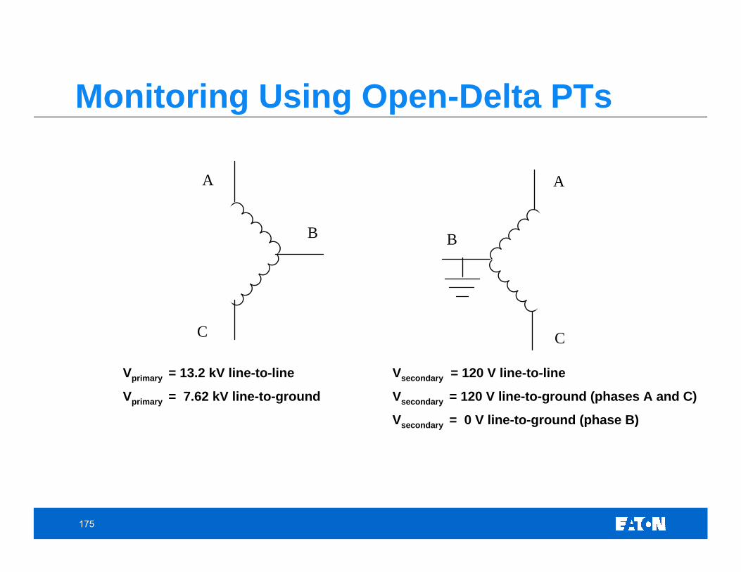
Vprimary = 13.2 kV line-to-line Vsecondary = 120 V line-to-line
Vprimary = 7.62 kV line-to-ground Vsecondary = 120 V line-to-ground (phases A and C)
Vsecondary = 0 V line-to-ground (phase B)
176
Outline• Introduction
• Describing a Power Quality Waveform • Sample PQ Monitoring Videos• Sample PQ Waveforms
• Monitoring Equipment • PQ Definitions • Power Quality Issues and Expected Waveforms
• Voltage Variations• Transients• Harmonics• Wiring and Grounding Considerations
• Power Quality Monitoring Considerations • The Evolution of Power Quality Data Acquisition Systems • Applying Uninterruptible Power Supplies: System Compatibility