The second generation of laser interferometricgravitational-wave detectors, such as the AdvancedLaser Interferometer Gravitational Wave Observato-ry1 and the Large-scale Cryogenic Gravitationalwave Telescope2 will make use of a technique calledresonant sideband extraction (RSE)3 to allow tuningof the detector’s frequency response and to improvethe peak sensitivity.
All previously investigated RSE interferometershave a signal extraction mirror added to the basicFabry–Perot Michelson interferometer configurationthat is employed by the first generation of interfero-metric gravitational-wave detectors.4–7 This mirror,placed at the dark port of the interferometer, couplesthe output field to the fields circulating in the armcavities to modify the resonant frequency and band-width for the signal sidebands in the interferometer.This configuration has been demonstrated with sev-eral different control schemes,8–12 but they all requireadditional radio-frequency (rf) components on the in-put light introducing bandwidth requirements on thephotodetectors that may be difficult to meet. The ex-
tra mirror used in these configurations for RSE in-creases the coupling between the control signals forthe various degrees of freedom, and the asymmetrictransmission of the rf sidebands to the detection portin the detuned configuration prevents the rf readoutscheme that is used for signal readout in the firstgeneration of detectors from being able to suppressphase modulator noise, making the feasibility of thisreadout scheme questionable for second-generationdetectors.13
An alternative RSE configuration based on polar-ization detection is presented here. It allows RSE tobe implemented without the signal extraction mirrorat the output port. As a result, power-recycled RSE,an advanced detector configuration, can be fully re-alized with the length sensing and signal readoutschemes used by the first generation of large-scaledetectors, thereby avoiding several issues that havebeen problematic in previous RSE configurations. Inthis paper we describe the polarization RSE configu-ration, present a mathematical model of the inter-ferometer, and report the results of a tabletopprototype of this configuration.
To understand the polarization RSE configurationand the motivation for its development, it is useful tobegin with a picture of a conventional power-recycledRSE interferometer, shown in Fig. 1.
The Michelson interferometer is sensitive to thedifferential strain induced by a passing gravitationalwave. When all the mirrors are positioned at theirintended operating points, the interference condition
P. T. Beyersdorf ([email protected]), S. Kawamura,and K. Somiya are with the National Astronomical Observatory ofJapan, 2-21-21 Osawa, Mitaka-shi, Tokyo 181-8588, Japan. F.Kawazoe is with Ochanomizu University, 2-21-1 Otsuka Bunkyou-ku, Tokyo 112-8610, Japan. M. Agüeros is with the Department ofAstronomy, University of Washington, Seattle, Washington 98195.
Received 17 September 2004; revised manuscript received 28January 2005; accepted 28 January 2005.
is such that the output port is held at a dark fringe.The Fabry–Perot cavities in the arms increase theeffective length, and hence the peak sensitivity, of theMichelson. The power-recycling mirror increases theeffective laser power in the interferometer by forminga resonant cavity for the reflected carrier field. Thegravitational-wave-induced signal sidebands exit thebeam splitter toward the signal extraction mirror,which reflects the signal sidebands back into the in-terferometer, and together with the mirrors of theFabry–Perot arm cavities (which, although split inseparate arms, can be modeled as a simple cavity)forms a three-mirror coupled cavity that the signalsidebands must pass through to reach the outputphotodetector. The resonant frequency of this coupledcavity is set by the microscopic positioning of thesignal extraction mirror. When it is positioned suchthat light at the carrier frequency would resonate inthis cavity, it is said to be a broadband configuration.In this configuration the interferometer is sensitiveover a relatively wide frequency band with a peakresponse at the dc. By detuning the cavity, movingthe signal extraction mirror a fraction of a wave-length to change the resonant condition, we can in-crease the interferometer’s peak sensitivity in anarrow frequency band, and the peak of the fre-quency response is shifted to a frequency that mightbe more interesting for gravitational-wave detection.
Controlling the position of the optics so that theinterferometer is held at the proper operating pointdespite the influence of external forces on the mirrorsdue to various noise sources is the job of the control
scheme. The mirror positions are relative quantitiesand are usually expressed in terms of the cavitylengths. A convenient way to describe the relativemirror positions is through the five quantities ��, ��,��, ��, and �s, defined in Table 1. The first four ofthese are relevant to power-recycled Fabry–PerotMichelson interferometer configurations of first-generation detectors whereas conventional RSE con-figurations also have the fifth degree of freedom �s.
The sensing of these length degrees of freedom issimilar for both RSE and non-RSE configurations: rfmodulation sidebands are imposed on the input lightof the interferometer.14 The frequency dependence ofthe cavities causes the different spectral componentsof the input light to propagate through the inter-ferometer with different efficiencies. Each componentof the light also accumulates a phase shift that is ameasure of one or more of the mirrors’ deviationsfrom the operating points. Detection and demodula-tion of the transmitted, reflected, and circulatinglight in the interferometer allow these phases to bedetected. From the detected signals and knowledge ofthe interferometer’s parameters, the four or five rel-evant cavity length errors are determined. This in-formation is fed back to the interferometer to keep allthe cavities resonant and the output port dark for thecarrier light. Uncertainties in any of the interferom-eter’s parameters or any measurement offsets limithow well the errors of each cavity can be determined.The sensitivity to these uncertainties and offsets ismuch greater when there are 5 degrees of freedom tobe sensed than when there are only 4. This effect ismost severe when the interferometer is far from itsoperating point, during lock acquisition. To lock all 5degrees of freedom to their desired operating points,it is necessary to first lock to one or a sequence ofintermediate configurations with a subset of these 5degrees of freedom controlled, adjusting the demod-ulation phases and servo gains at each step.
In addition to hampering the lock acquisition pro-cess, the addition of a fifth degree of freedom compli-cates the signal readout scheme. The signalextraction cavity length is sensed by an additional rfsideband or sidebands on the input light. The fre-quency of this sideband is generally chosen to bemuch higher than the other rf sidebands (180 versus9 MHz in the Advanced LIGO baseline design) sothat the difference in coupling to the signal extractioncavity by the asymmetric length of the Michelsoninterferometer is maximized, allowing the most ro-
Fig. 1. Conventional power-recycled RSE interferometer config-uration with a 50–50 beam splitter (BS) forming a Michelsoninterferometer with high-finesse Fabry–Perot cavities in the arms.The mirror positions are set such that the interference condition atthe beam splitter causes the carrier power to return toward thepower-recycling mirror (PRM) while the gravitational-wave signalsideband goes toward the signal extraction mirror (SEM).
Table 1. Five Relevant Length Degrees of Freedom of a Power-Recycled RSE Interferometera
Degree of Freedom Symbol Physical DistanceValue for Carrier at
bust sensing of ls, the signal extraction cavitylength. Tuning of the interferometer is achieved byadjustment of the frequency of the high-frequencysideband and in some configurations the macroscopiclength of the signal extraction cavity. This requiresthe demodulation phase to be reoptimized every timethe detuning is changed and limits the allowable val-ues of the detuning to those that have correspondingrf sideband frequencies allowable given the con-straints placed by the need to avoid frequencies nearwhich the arm cavities are resonant. This high-frequency rf sideband, not used in first-generationdetectors, places a challenging requirement on thephotodetector—not only must it be capable of han-dling the high power used in an interferometricgravitational-wave detector, but it must also be fastto detect signals at the higher rf. In addition, in adetuned configuration the transmission of any rf side-bands to the dark port is asymmetric, causing onesideband to transmit more efficiently than the other.When used as a local oscillator for a gravitational-wave signal, this imbalance in the sidebands allowsphase noise from the phase modulator or residualcarrier field at the dark port to couple to the detectedsignal, raising concern over the feasibility of rf signalreadout in second-generation detectors.
To develop polarization RSE, the goal was to createa RSE topology that could be controlled with a well-understood and thoroughly tested control scheme.The polarization RSE configuration transmits the rfsidebands symmetrically to the dark port photodetec-tor and furthermore does not require use of an addi-tional rf modulation frequency to control the signalextraction cavity, so control of the polarization RSEand readout of the gravitational-wave signal is sim-ilar to that of first-generation detectors.
With polarization RSE, as shown in Fig. 2, all thelight enters and exits the Michelson interferometerthrough the same face of the polarizing beam splitter.A differential phase shift between the arms manifestsitself as a change in the polarization state of thereflected light, rather than a change in the magni-tude of the field at the output of the beam splitter. Atthe operating point in the absence of a signal, thepolarization state is unchanged from input to output,and all the light exits in the bright polarization. Adifferential phase shift in the arms causes some of theoutput light to become polarized in the orthogonaldark polarization.
In this configuration all the light reflects from theMichelson interferometer toward the recycling mir-ror. The bright polarization reflected by the recyclingmirror increases the effective power in the inter-ferometer, as in power recycling, and the dark polar-ization reflected by the recycling cavity interacts withthe fields in the arm cavities to modify their resonantfrequency and bandwidth for differential signals, asin signal extraction. Thus the single recycling mirrortakes the place of both the power-recycling mirror
and the signal extraction mirror so that RSE can beused with only the 4 degrees of freedom present innon-RSE configurations. Polarization-sensitive ele-ments in the recycling cavity allow the parameters ofthe cavity to differ for the two polarizations so thatthe signal extraction cavity can have a differentbandwidth and can be detuned from the power-recycling cavity even though they are just two differ-ent polarization states of the same physical cavity. Inthis configuration the basic control scheme developedfor first-generation detectors can be used. The lengthsensing scheme is shown in Fig. 3. It is completelyanalogous to that of a (non-RSE) power-recycledFabry–Perot interferometer. Port 1 corresponds tothe pickoff port since it contains only components ofthe light that were resonate in the recycling cavity.Port 2 corresponds to the dark port as it contains thedark polarization component for which the carrierinterferes destructively and a fraction of the first-order sidebands that were resonate in the recyclingcavity. Port 3 corresponds to the bright port since itcontains the bright polarization component of thelight that resonates in the recycling cavity as well asall the components of the input light that are notresonate in the recycling cavity.
To analyze the control scheme and the response togravitational waves for this configuration, it is usefulto consider a mathematical model in which Jonescalculus15 is used to represent the full polarization-dependent nature of the interferometer.
4. Mathematical Model of the Interferometer
In Jones calculus the amplitude of polarized light isrepresented by a 2 � 1 vector, and the action of anoptical element on the light is represented by a 2
Fig. 2. Polarization RSE interferometer configuration showingthe polarization state of light at four locations in the interferom-eter. The interferometer contains several polarization-sensitive op-tics: a polarizing beam splitter (PBS), a variable wave plate (V), ahalf-wave plate (H), and an input–output coupler (IOC). Lx and Ly
are the lengths between the near mirror (N) and the far mirror (F)in the x- and y-arm cavities, respectively. lx and ly are the distancesfrom the near mirrors to the polarizing beam splitter in the x andy arms, respectively, and lp is the length from the polarizing beamsplitter to the recycling mirror (RM).
� 2 matrix. The propagation of light through an op-tical system is represented by the product of theJones vector for the input field with the Jones matrixfor the optical system. We define the Jones vector by
E � �Ep
Es�, (1)
where Ep is the p-polarized component and Es is thes-polarized component of the electric field (corre-sponding to horizontal and vertical polarization, re-spectively, in the laboratory frame used for thispaper). Table 2 summarizes the matrices necessary tomodel the polarization RSE interferometer.
We can find the steady-state solution for the fieldsin the interferometer, as shown in Fig. 4, by express-ing the relationships between the fields using Jonesmatrices. Treating the propagation delay in the recy-cling cavity as occurring entirely between the input–output coupler and the variable wave plate, theserelations are
Ea � (Rrm)1�2Ea�, (2)
Ec � �iocEa � �iocEb, (3)
Ed � �iocEa � �iocEb, (4)
Ee � exp(iklp)��Ed, (5)
Ef � �pbsEe, (6)
Eg � exp(ikly)Ef, (7)
Eh � i(Tn, y)1�2Eg � (Rn, y)
1�2Eh�, (8)
Ei � exp(ikLy)Eh, (9)
Fig. 3. Control scheme for the polarization RSE interferometer byuse of frontal modulation with a single rf modulation frequencydriving the electro-optic modulator (EOM). Demodulation occurs atthe three output ports shown in the dashed boxes labeled ports 1,2, and 3. A Faraday isolator (FI) is used to separate the reflectedsignals.
Table 2. Jones Matrices Necessary to Model the Polarization RSE Interferometer
Symbol Element Jones Matrix
�ioc Transmission through a window at nonnormal incidence with powertransmission Tp for p polarization and Ts for s polarization i��Tioc, p�1�2 0
0 �Tioc, s�1�2��ioc Reflection from a window at nonnormal incidence with power
reflectivity Rp for p polarization and Rs for s polarization ��Rioc, p�1�2 00 �Rioc, s�1�2�
� Half-wave plate with a fast axis at 22.5 deg from vertical 1
�2��1 1
1 1�� Variable wave plate with retardation � and vertical fast axis �exp�i�� 0
0 1��pbs Transmission through a polarizing beam splitter with fractional
power leakage Cp in transmission and Cs in reflection i��Cp�1�2 00 �1�Cs�1�2�
�pbs Reflection from an ideal polarizing beam splitter with fractionalpower leakage Cp in transmission and Cs in reflection ��1�Cp�1�2 0
0 �Cs�1�2�
Fig. 4. Fields in the polarization RSE interferometer.
where Rrm is the (power) reflection coefficient of therecycling mirror; Tn, x, Rn, x and Tn, y, Rn, y are thetransmission and reflection coefficients for the armcavity mirrors nearest the polarizing beam splitter inthe x and y arms, respectively; and Tf, x, Rf, x andTf, y, Rf, y are the transmission and reflection coeffi-cients for the arm cavity mirrors furthest from thepolarizing beam splitter in the x and y arms, respec-tively. The solution to Eqs. (2)–(25) gives the steady-state fields in the interferometer, useful forunderstanding the control scheme and the inter-ferometer’s response to gravitational waves.
A. Control Scheme
The static response of the interferometer illuminatesthe choice of signals for length sensing. We calculateit considering only a small static deviation in themirror positions relative to the operating point for thecarrier and each of the sideband frequencies. For onlya single, classical input field so that Ec� � Ej� � Eq�� 0, we can determine the fields in the interferometerby solving Eqs. (2)–(25). Identifying the field in the
recycling cavity as Erc � Ed� and the input field asEb � Ein, the fields reflected from and transmittedthrough the interferometer Er � Eb� and Et � Ec arelinearly dependent on the field in the recycling cavitysuch that
Er � �iocErc, (26)
Et � (Rrm)1�2�ioc�iocErc � �iocEin. (27)
Thus it is sufficient to express the response of thefield in the recycling cavity that is due to static offsetsin the length degrees of freedom.
For small deviations from the operating point suchthat
�� � 2(Lx � Ly)�c � ��mod 2�, (28)
�� � 2(Lx � Ly)�c � ��mod 2�, (29)
�� � (2lp � lx � ly)�c � ��2 � ��mod 2�, (30)
�� � (lx � ly)�c � ��2 � ��mod �, (31)
where � is the frequency of the rf sidebands relativeto the carrier, and assuming a linearly polarized in-put field
Ein � �01�Ein; (32)
unit reflectivity arm cavity end mirrors
Rf, x � Rf, y � 1, (33)
Tf, x � Tf, y � 0; (34)
and cavity near mirrors with matched reflection andtransmission coefficients
Rn, x � Rn, y � Rn, (35)
Tn, x � Tn, y � Tn; (36)
with an ideal polarizing beam splitter such that
Cp � Cs � 0, (37)
the components of the field in the recycling cavity areto first order in ��, ��, ��, and ��.
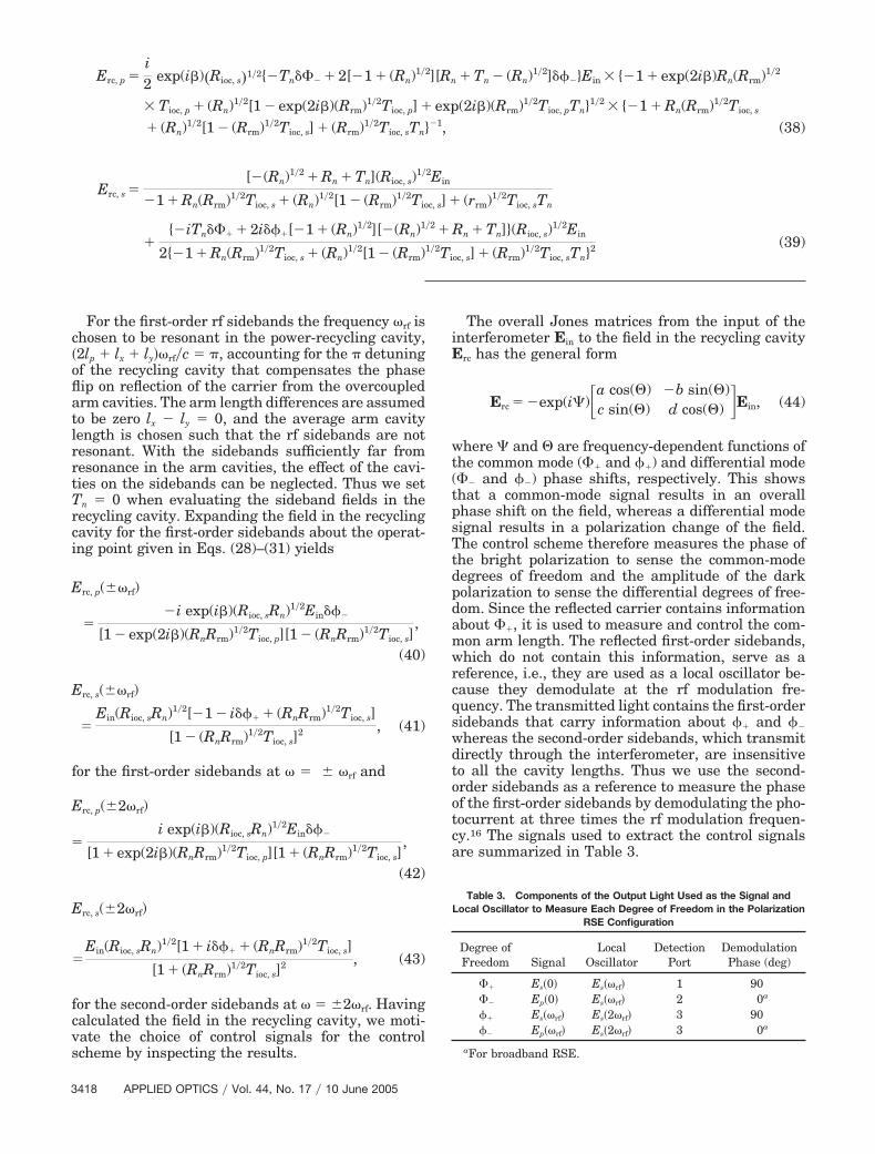
For the first-order rf sidebands the frequency rf ischosen to be resonant in the power-recycling cavity,�2lp � lx � ly�rf�c � �, accounting for the � detuningof the recycling cavity that compensates the phaseflip on reflection of the carrier from the overcoupledarm cavities. The arm length differences are assumedto be zero lx � ly � 0, and the average arm cavitylength is chosen such that the rf sidebands are notresonant. With the sidebands sufficiently far fromresonance in the arm cavities, the effect of the cavi-ties on the sidebands can be neglected. Thus we setTn � 0 when evaluating the sideband fields in therecycling cavity. Expanding the field in the recyclingcavity for the first-order sidebands about the operat-ing point given in Eqs. (28)–(31) yields
for the second-order sidebands at � �2rf. Havingcalculated the field in the recycling cavity, we moti-vate the choice of control signals for the controlscheme by inspecting the results.
The overall Jones matrices from the input of theinterferometer Ein to the field in the recycling cavityErc has the general form
where � and � are frequency-dependent functions ofthe common mode (�� and ��) and differential mode(�� and ��) phase shifts, respectively. This showsthat a common-mode signal results in an overallphase shift on the field, whereas a differential modesignal results in a polarization change of the field.The control scheme therefore measures the phase ofthe bright polarization to sense the common-modedegrees of freedom and the amplitude of the darkpolarization to sense the differential degrees of free-dom. Since the reflected carrier contains informationabout ��, it is used to measure and control the com-mon arm length. The reflected first-order sidebands,which do not contain this information, serve as areference, i.e., they are used as a local oscillator be-cause they demodulate at the rf modulation fre-quency. The transmitted light contains the first-ordersidebands that carry information about �� and ��
whereas the second-order sidebands, which transmitdirectly through the interferometer, are insensitiveto all the cavity lengths. Thus we use the second-order sidebands as a reference to measure the phaseof the first-order sidebands by demodulating the pho-tocurrent at three times the rf modulation frequen-cy.16 The signals used to extract the control signalsare summarized in Table 3.
The control signals for the differential degrees offreedom �� and �� are generated with a local oscil-lator that is orthogonally polarized to the signal. Thisis accomplished with a balanced detection tech-nique17 where the sum and difference of these polar-ization components are projected onto twophotodetectors that have their signals subtracted.
B. Gravitational-Wave Response
The dynamic response of the interferometer is used tocalculate the response to gravitational waves. Forthis calculation all the length degrees of freedom areassumed to be held at their operating point by thecontrol scheme. The conversion of carrier light in thearms to signal sidebands at frequency � by a gravi-tational wave is treated as fields injected through thefar mirror of the arms that are proportional to thearm fields and the gravitational-wave amplitude18
according to
Eq�() �i
(Tf, x)1�2
0
sin (Lx�c)h()En�(0), (45)
Ej�() � �i
(Tf, y)1�2
0
sin (Ly�c)h()Ei�(0), (46)
where h�� is the spectral density of a gravitationalwave at normal incidence with a polarization alignedto the arms of the interferometer. The resulting Jonesmatrix used to relate the input carrier light to thesignal sidebands exiting the interferometer satisfies
Ec() � Eb�() � �()h()Ein(0). (47)
Here x12��, the off-diagonal term of ���, is thetransfer function of the interferometer giving the re-sponse to gravitational-wave signals:
x12() � GcarGsig
0
sin(L�c)h, (48)
with
where 0 � 2�c�� is the angular frequency of thelaser, L � Lx � Ly is the arm cavity lengths (assumedto be identical), l � lp � �lx � ly��2 is the recyclingcavity length, An � 1 � Rn � Tn is the loss in the nearmirrors, and the arm lengths are assumed to be iden-tical �lx � ly�.
This response has a resonant peak at a tunablefrequency that depends on �, the retardance of thewave plate in the recycling cavity, as can be seen inFig. 5.
5. Tabletop Prototype
We built a tabletop polarization RSE interferometerto demonstrate this configuration. We first selectedthe modulation frequency of 18.8 MHz to be compat-ible with the electronics and modulators we hadavailable. This frequency defines the overall length ofthe recycling cavity as described in the next para-graph. The choice of other lengths in the interferom-eter is less critical and was primarily driven by spaceconstraints on the optical table:
Lx � 17.5 cm, (51)
Ly � 17.5 cm, (52)
lx � ly � 30 cm. (53)
Schnupp asymmetry (having lx � ly), which is usuallyused to couple rf sideband power to the dark port, was
forsaken in this setup because the polarizing beamsplitter used to separate the dark polarization fromthe bright polarization was somewhat leaky allowingit to provide this coupling.
Because of the relatively short arm cavity length,the sidebands reflected from the arm cavity were suf-
Fig. 5. Response of a polarization RSE interferometer. The am-plitude is referenced to the dc response of the broadband configu-ration. The interferometer parameters are l� � 5 m, L� � 300 m,rn � 0.9994, tioc, p � 0.95, and tioc, s � 0.74. Curves for severaldetunings are shown.
ficiently close to resonance (13 linewidths) that theyexperience a nonnegligible phase shift of ��� 0.075 rad. With this phase shift, the 18.8-MHzfrequency modulation, and the requirement that thesidebands resonate in the recycling cavity when thecarrier is resonant in the recycling cavity and the armcavities, the total recycling cavity length is set by theconstraint
lp �lx � ly
2 �c2f �1 �
��
� � 4.08 m. (54)
The arm cavities consist of a high-reflector far mir-ror and a near mirror with 99% power reflectivity fora finesse of 600. The cavity mirrors and the recyclingmirror are mounted on piezoelectric actuators to con-trol the cavity lengths. The observed power reflectiv-ity for the carrier when on resonance in the armcavities was only 4%, much lower than the 99% the-oretical reflectivity. We were unable to improve thecarrier reflectivity by adjusting the cavity alignment,or by replacing the cavity mirrors (with new but nom-inally identical mirrors). This suggests a loss internalto the arm cavity likely due to a combination of theinherent coating loss on the mirrors and some con-tamination of their surfaces totaling 1.4%. Because ofthis loss the power-recycling gain was less than uni-ty; the power-recycling cavity suppressed the carrierpower by a factor of 2 when resonant and a factor of32 when antiresonant. Although this suppression de-grades the sensitivity of the interferometer, it doesnot change the dynamics of the control system. Sincethis prototype was intended to demonstrate the con-trol system, not low-noise operation, we continuedthe experiment without resolving the issue of theunexpected loss in the arm cavities.
Figure 6 shows the layout of the tabletop inter-ferometer. A calibrated Berek-style variable waveplate from New Focus consisting of a birefringentcrystal that can be tilted to change the internal pathlength, and hence the birefringence of the wave plate,was double passed in the recycling cavity. A 1% pick-off in the recycling cavity was used for monitoringand diagnostic purposes. One beam from the pickoffwas used to monitor the power inside the recyclingcavity, and the other was monitored by a scanningconfocal Fabry–Perot-type optical spectrum analyzer(OSA) to observe the optical spectrum of the lightcirculating in the recycling cavity.
The other elements in the recycling cavity were theinput–output coupler, a half-wave plate, and themain polarizing beam splitter. The input–output cou-pler was a low-reflectivity beam-splitting plate ori-ented to have an incident angle of 50 deg yielding apower reflection coefficient of 10% for the s polariza-tion and 5% for the p polarization. The beam splitterfor the Michelson interferometer was a 90-deg polar-izing beam-splitter cube. The extinction ratio intransmission is 1000:1 but in reflection it is only 20:1.This introduced a small coupling between signals for
the x and y arms, but was not enough to prevent lockacquisition or operation of the interferometer.
A. Input Field
The desired input field consists of a frequency-modulated laser with sideband pairs at only the fun-damental modulation frequency and the secondharmonic of this frequency. Any sidebands at thethird harmonic of the modulation frequency are prob-lematic because they beat with the carrier at 3rf, thesame frequency as the signals used to control �� and��, which come from the beat of the first- and second-order sidebands at �rf and �2rf, respectively.
The main laser is a 200-mW InnoLight Nd:YAGnonplanar ring oscillator with a wavelength of1064 nm. The rf sidebands were generated by a phasemodulator driven at rf � 18.8 MHz with a modula-tion depth of 0.5. At this modulation depth a suffi-ciently large amplitude of the first- and second-ordersidebands is generated. A nonnegligible amplitude ofthird-order sidebands is also produced. To suppressthese unwanted third-order sidebands, the modula-tion waveform was not sinusoidal, but rather wastailored to avoid their generation. An 18.8-MHz sinewave was combined with a 56.4-MHz sine wave ofappropriate amplitude and phase to cancel thewould-be third-order sidebands. We generated thiswaveform by splitting the output of a voltage-
Fig. 6. Schematic of the tabletop polarization RSE interferome-ter. The dashed line is the secondary beam used for lock acquisi-tion. PZT, piezoelectric transducer; EOM, electro-optic modulator;mon PD, monitored photodiode.
controlled oscillator. One output was amplified to a5-V sine wave and the other was used to drive atransistor into saturation producing an 18.8-MHzsquare wave. The square wave was filtered at56.4 MHz to extract the third-harmonic component.This third-harmonic signal was attenuated with avariable attenuator, and we set its phase by adjustingthe cable lengths before we recombined the signalwith the 18.8-MHz component. This waveform wasamplified to approximately 30 V peak to peak by apassive resonant transmission line and was used todrive a broadband electro-optic modulator.
The laser field exiting the phase modulator wasmonitored with an OSA, and the relative amplitudeand phase of the frequency-tripled component of thedriving waveform was adjusted to null the amplitudeof the third-harmonic optical sideband. Once an ac-ceptable spectrum was obtained, the OSA was re-moved and the rf waveform was not inspected oradjusted again.
B. Lock Acquisition
A useful advantage of the polarization RSE is theability to cleanly separate the control signals for the4 length degrees of freedom during lock acquisition.Although the configuration shown in Fig. 3 and theassociated control scheme described in Table 1 canreliably control the interferometer when all degreesof freedom are near their operating point, during lockacquisition, when this condition is not met, an aux-iliary interferometer, in which the otherwise unusedface of the polarizing beam splitter is used, assists inlocking the arms.
In our experiment a pickoff upstream of the inter-ferometer generates a secondary beam that is in-jected into the otherwise unused face of the polarizingbeam splitter. The polarization of the secondarybeam is set by a half-wave plate so that the light issplit evenly by the polarization beam splitter. A pick-off of the returning beam is split by a polarizing beamsplitter and detected by a pair of photodiodes. Thepolarization is such that each photodiode sees lightfrom a different arm. This allows the arm cavities tobe independently locked by Pound–Drever–Hall lock-ing19; since this secondary beam never encounters therecycling mirror and the arm cavity signals are sep-arated by polarization, the signals for the arm cavi-ties are not affected by the state of the other armcavity, the differential Michelson, or the recyclingcavity length; therefore the arms can be locked ro-bustly regardless of the state of the rest of the inter-ferometer.
The remaining 2 degrees of freedom are locked bythe light from the main beam exiting the recyclingcavity. The first-order rf sidebands must be resonantin the recycling cavity before they can be used togenerate the Michelson error signal. In practice, theMichelson servo is first engaged, while the recyclingcavity length is adjusted to be near resonance. Oncethe recycling cavity is near resonance, the recyclingcavity servo is engaged and both degrees of freedomlock simultaneously.
C. Length Control
Once all 4 degrees of freedom are locked, the sensingof the arm cavities is switched to the signals from ��
and �� described in Table 3, which have a highersignal-to-noise ratio due to the higher laser power inthe main beam. The �� and �� signals are fed backto the end mirrors of the arm cavities that are con-trolled by the signals from the secondary beam usedfor lock acquisition. The secondary beam is thenblocked so that the interferometer is controlled en-tirely by the signals from frontal modulation. Figure7(a) shows a typical lock acquisition sequence whenthe recycling cavity and the Michelson are lockedbefore the arm cavities. Figure 7(b) shows a lock ac-quisition sequence when the arm cavities are lockedfirst. This shows one strength of this configuration:
Fig. 7. Total intracavity power in the recycling cavity (top traces),the intracavity power in the dark polarization (second traces), andthe power transmitted through the x- and y-arm cavities (third andfourth traces, respectively) as the interferometer is brought to theoperating point during typical lock acquisitions. In (a) the armcavities are locked after the recycling cavity and the Michelson. In(b) the arm cavities are locked first. The apparent difference of thenoise level between the two plots is due only to the traces beingrecorded at different times when the alignment of the photodiodesused to monitor the signals had changed.
The control signals are largely independent, evenduring lock acquisition.
The differential Michelson was the most trouble-some degree of freedom. This is because the localoscillator is several orders of magnitude smaller thanthose for the other degrees of freedom. The second-order sidebands in the bright polarization are used asthe local oscillator. They leak through a polarizingbeam splitter to detect the dark polarization of thefirst-order sidebands. The amplitude is several ordersof magnitude smaller than the local oscillator fieldsfor the other degrees of freedom because the second-order sidebands have a relatively small amplitude tobegin with because of the low modulation depth of thephase modulator, and then only a small fraction (ap-proximately 5%) leaks through the polarizing beamsplitter for detection. The low signal-to-noise ratio forthis degree of freedom resulted in a strong sensitivityto electronic offsets and required that this controlsignal be frequently calibrated. With the high laserpower in full-scale detectors, however, this would notbe an issue.
D. Frequency Response
The measurement of the transfer function of the in-terferometer to show the effect of detuning with RSErequires that the signals be measured at frequenciesseveral times higher than the �1.4-MHz� linewidth ofthe arm cavities. Since these frequencies are too highto mechanically shake the arm mirrors to generatesignals for the transfer function, a laser with an offsetfrequency was injected through the end mirror of onearm cavity to simulate gravitational-wave-inducedsignal sidebands. The laser was phase locked to themain laser as shown in Fig. 8 with an adjustableoffset frequency. Pickoffs from both the main laserand the auxiliary laser were combined on a photode-tector producing a beat signal at the frequency dif-ference of the lasers. This beat signal was mixed witha sine wave from a network analyzer, low-pass fil-tered, and fed back to the frequency control of theauxiliary laser. When the auxiliary laser frequency isadjusted to be near the main laser frequency so thatthe beat signal is within the bandwidth of the photo-detector and other electronics in the feedback loop,this error signal locks the auxiliary laser to the main
laser with a frequency offset controlled by the net-work analyzer. Although the large tuning range ofthe laser �30 GHz� relative to the photodetector’sbandwidth �200 MHz� made the initial acquisition ofa signal difficult, once the lasers were locked, thelocking was robust and could be maintained for theduration of our experiments.
The auxiliary laser is a 100-mW Lightwave 126Nd:YAG nonplanar ring oscillator with a wavelengthof 1064 nm. It was injected through the far mirror ofone arm cavity. Although injecting a signal into onlyone arm is equivalent to introducing sidebands in thedifferential mode and the common mode, the separa-tion of signals based on polarization and the balancedphotodetection method assure that only the differen-tial mode signals are measured by the appropriatedetector. Several plots of the response are shown inFig. 9 for several detuning values set by the birefrin-gence in the recycling cavity.
We measured the transfer functions, shown in Fig.9, by sweeping the sine wave generated by the net-work analyzer while measuring the amplitude of thedemodulated signal from the L� photodetector. Aftereach measurement, we changed the birefringence inthe recycling cavity by adjusting the tilt of the Berekwave plate. This was done without breaking the lockand without the need to change any parameters ofthe control scheme.
E. Output Light Spectrum
Balanced rf sidebands are necessary for low-noise rfreadout of a gravitational-wave signal. To demon-strate that the rf sidebands used for the signal read-out are balanced, the optical spectrum of the light inthe recycling cavity was measured for several valuesof detuning. The spectra, shown in Fig. 10, were re-corded by the scanning confocal Fabry–Perot spec-trum analyzer monitoring a pickoff of the light in therecycling cavity. We calibrated the horizontal axis bysetting the value of the carrier to zero and the lowersideband to 18.8 MHz, the independently measuredrf modulation frequency. Although the detuningcauses the spectrum of the signal sidebands in thedark polarization to become unbalanced as the re-sponse peak is shifted away from the dc, the rf side-
Fig. 8. Offset phase locking of the auxiliary laser used to simulatea gravitational-wave-induced sideband. When phase locked, thefrequency of the auxiliary laser differs from the main laser by s.LPF, low-pass filter. Fig. 9. RSE tuning curves for the polarization RSE prototype
interferometer showing both measured (solid curves) and calcu-lated (dotted curves) values for several different detunings.
bands, which are in the bright polarization, areunaffected; the spectra of Fig. 10 show no systematicimbalance. This is significant because it is unlike allother RSE configurations that have been investigatedand allows the rf signal readout to be used withoutintroducing technical noise from the phase modulatorthat couples in when the rf sidebands are unbal-anced.
6. Summary
We have introduced a resonant sideband extractionscheme in which polarization detection is used toreduce the number of length degrees of freedom from5 to 4. We presented a mathematical model in whichwe used Jones calculus to describe the configurationand illuminate the choice of signals used for the con-trol scheme. We showed that a tabletop prototypeinterferometer can be locked and controlled with acontrol scheme similar to that currently used byTAMA300 for control of a non-RSE power-recycledFabry–Perot Michelson interferometer. The peak fre-quency response of the interferometer is continuouslytunable by means of adjusting the birefringence inthe recycling cavity. The strength of this configura-tion is that because it has the same 4 degrees offreedom as first-generation detectors, and because,even when the frequency response is detuned, the rfsidebands are balanced at the detection port, it allowsthe readout and control schemes that have alreadybeen proven in large-scale detectors to be used with afrequency-tunable (RSE) configuration. Further-more, the frequency response of this configuration iscontinuously tunable without breaking the lock; andbecause it does not require a length asymmetry in theMichelson, the coupling of laser frequency noise tothe output port can be eliminated.
Although its primary strength is that it has a famil-iar and well-tested control scheme, the trade-off is thatthe optical configuration, with many polarization-sensitive elements, has never been used in a large-scale gravitational-wave detector. Therefore severalissues must still be resolved before this configuration
can be implemented in a gravitational-wave detector.These include investigation of the tolerances (such asallowable motion of the wave plates in the roll mode)imposed by the polarization-sensitive optics and inves-tigation of the quality and availability of large-sizepolarizing beam splitters and wave plates.
We thank the Advanced Interferometer Configura-tions working group of the LIGO Science Collabora-tion for helpful discussions during this study. Thisresearch is supported by a Grant-in-Aid for ScientificResearch of the Ministry of Education, Culture,Sports, Science, and Technology. Marcel Agüeros ac-knowledges support from the National Science Foun-dation’s Summer Program in Japan.
References1. P. Fritschel, “The second generation LIGO interferometers,”
AIP Conf. Proc. 575, 15–23 (2001).2. K. Kuroda, M. Ohashi, S. Miyoki, D. Tatsumi, S. Sato, H.
Ishizuka, M. Fujimoto, S. Kawamura, R. Takahashi, T.Yamazaki, K. Arai, M. Fukushima, K. Waseda, S. Telada, A.Ueda, T. Shintomi, A. Yamamoto, T. Suzuki, Y. Saito, T. Ha-ruyama, N. Sato, K. Tsubono, K. Kawabe, M. Ando, K. Ueda,H. Yoneda, M. Musha, N. Mio, S. Moriwaki, A. Araya, N.Kanda, and M. E. Tobar, “Large-scale Cryogenic GravitationalWave Telescope,” Int. J. Mod. Phys. D 8, 557–579 (1999).
3. J. Mizuno, K. A. Strain, P. G. Nelson, J. M. Chen, R. Schilling,A. Rüdiger, W. Winkler, and K. Danzmann, “Resonant side-band extraction: a new configuration for interferometricgravitational-wave detectors,” Phys. Lett. A 175, 273–276(1993).
4. A. Abramovici, W. Althouse, R. Drever, Y. Gursel, S.Kawamura, F. Raab, D. Shoemaker, L. Sievers, R. Spero, K.Thorne, R. Vogt, R. Weiss, S. Whitcomb, and M. Zucker,“LIGO: the Laser Interferometer Gravitational-Wave Obser-vatory,” Science 256, 325–333 (1992).
5. C. Bradaschia, R. D. Fabbro, A. D. Virgilio, A. Giazotto, H.Kautzky, V. Montelatici, D. Passuello, A. Brillet, O. Cregut, P.Hello, C. N. Man, P. T. Manh, A. Marraud, D. Shoemaker, J. Y.Vinet, F. Barone, L. D. Fiore, L. Milano, G. Russo, J. M. Agu-irregabiria, H. Bel, J. P. Duruisseau, G. L. Denmat, P. Tour-renc, M. Capozzi, M. Longo, M. Lops, I. Pinto, G. Rotoli, T.Damour, S. Bonazzola, J. A. Marck, Y. Gourghoulon, L. E.Holloway, F. Fuligni, V. Iafolla, and G. Natale, “The Virgoproject: a wide band antenna for gravitational wave detection,”Nucl. Instrum. Methods Phys. Res. A 289, 518–525 (1990).
6. K. Danzmann, H. Lück, A. Rüdiger, R. Schilling, M. Schrem-pel, W. Winkler, J. Hough, G. P. Newton, N. A. Robertson, H.Ward, A. M. Campbell, J. E. Logan, D. I. Robertson, K. A.Strain, J. R. J. Bennett, V. Kose, M. Kühne, B. F. Schutz, D.Nicholson, J. Shuttleworth, H. Welling, P. Aufmuth, R. Rink-leff, A. Tünnermann, and B. Willke, “GEO 600: a 600-m laserinterferometric gravitational wave antenna,” in First EdoardoAmaldi Conference on Gravitational Wave Experiments, E.Coccia, G. Pizella, and F. Ronga, eds. (World Scientific, Singa-pore, 1995), pp. 100–111.
7. K. Tsubono, “300-m laser interferometer gravitational wavedetector TAMA 300 in Japan,” in First Edoardo Amaldi Con-ference on Gravitational Wave Experiments, E. Coccia, G. Pi-zella, and F. Ronga, eds. (World Scientific, Singapore, 1995),pp. 112–114.
8. J. E. Mason and P. A. Willems, “Signal extraction and opticaldesign for an advanced gravitational-wave interferometer,”Appl. Opt. 42, 1269–1282 (2003).
9. G. Müller, T. Delker, D. B. Tanner, and D. Reitze, “Dual-recycled cavity-enhanced Michelson interferometer for
Fig. 10. Optical spectrum of the light resonating in the recyclingcavity for various values of detuning.
10. D. A. Shaddock, M. B. Gray, C. Mow-Lowry, and D. E. McClel-land, “Power-recycled Michelson interferometer with resonantsideband extraction,” Appl. Opt. 42, 1283–1295 (2003).
11. O. Miyakawa, K. Somiya, G. Heinzel, and S. Kawamura, “De-velopment of a suspended-mass RSE interferometer usingthird harmonic demodulation,” Class. Quantum Grav. 19,1555–1560 (2002).
12. K. Somiya, “Investigation of radiation pressure effect in afrequency-detuned interferometer and development of thereadout scheme for a gravitational-wave detector,” Ph.D. dis-sertation (University of Tokyo, 5-1-5 Kashiwanoha, Kashiwa,Chiba, Tokyo, Japan, 2004).
13. P. Fritschel, “DC readout for Advanced LIGO,” presented atthe LIGO Science Collaboration meeting, Hannover, Germany,18–21 August 2003, http://www.ligo.caltech.edu/docs/G/G030460-00/.
14. M. W. Regehr, F. J. Raab, and S. E. Whitcomb, “Demonstrationof a power-recycled Michelson interferometer with Fabry–
Perot arms by frontal modulation,” Opt. Lett. 20, 1507–1509(1995).
15. E. Hecht, Optics, 3rd ed. (Addison-Wesley, Reading, Mass.,1998), pp. 321–326.
16. K. Arai, M. Ando, S. Moriwaki, K. Kawabe, and K. Tsubono,“New signal extraction scheme with harmonic demodulationfor power-recycled Fabry-Perot-Michelson interferometers,”Phys. Lett. A 273, 15–24 (2000).
17. K.-X. Sun, E. K. Gustafson, M. M. Fejer, and R. L. Byer,“Polarization-based balanced heterodyne detection method ina Sagnac interferometer for precision phase measurement,”Opt. Lett. 22, 1359–1361 (1997).
18. J. Mizuno, “Comparison of optical configurations for laser-interferometric gravitational-wave detectors,” Ph.D. disserta-tion (Max-Plank-Institut für Quantumoptik, Garching,Bundersrepublik, Deutschland, 1995).
19. R. W. P. Drever, J. L. Hall, F. V. Kowalski, J. Hough, G. M.Ford, A. J. Munley, and H. Ward, “Laser phase and frequencystabilization using an optical resonator,” Appl. Phys. B 31,97–105 (1983).