30
Power Savings by Impeller Replacements for Main Fan Stations in the SA Gold Mining Industry Presented by: • John-John Fourie
| Date post: | 18-Dec-2015 |
| Category: |
Documents |
| Upload: | sydney-bond |
| View: | 213 times |
| Download: | 0 times |

Power Savings by Impeller Replacements for Main Fan Stations in
the SA Gold Mining Industry
Presented by:• John-John Fourie

Agenda
• Introduction• Potential savings - Typical mine fan• Theory, Fan laws and Fan curves• Energy Saving Options• Drop-in Impeller Replacement• Conclusion

Introduction• Typically 250kW to 2.2MW per single fan can be
consumed• Potential financial savings significant • Intervention methods include centrifugal fan impellers
modifications
Potential savings - Typical Mine Fan
0 20 40 60 80 100 120 140 160 180 2000
500
1000
1500
2000
2500
3000
3500
4000
4500
5000
5500
6000
6500
0%
10%
20%
30%
40%
50%
60%
70%
80%
90%
100%
Volume Flow (m3/s)
Stati
c Pre
ssur
e (P
a)
Efficie
ncy
(%)
Original duty
Actual duty

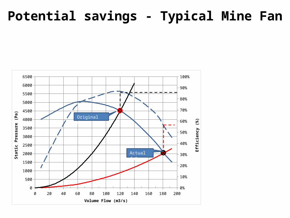
Potential savings - Typical Mine Fan
Actual efficiency of 55% is much lower than the original,
selected efficiency of 80%
0 20 40 60 80 100 120 140 160 180 2000
500
1000
1500
2000
2500
3000
3500
4000
4500
5000
5500
6000
6500
0%
10%
20%
30%
40%
50%
60%
70%
80%
90%
100%
Volume Flow (m3/s)
Stati
c Pre
ssur
e (P
a)
Efficie
ncy
(%)
Original duty
Actual duty
0 20 40 60 80 100 120 140 160 180 2000
500
1000
1500
2000
2500
3000
3500
4000
4500
5000
5500
6000
6500
0
50
100
150
200
250
300
350
400
450
500
550
600
650
700
750
Volume Flow (m3/s)
Stati
c Pre
ssur
e (P
a)
Pow
er (k
W)
Original duty
Actual duty
Potential savings - Typical Mine Fan

0 20 40 60 80 100 120 140 160 180 2000
500
1000
1500
2000
2500
3000
3500
4000
4500
5000
5500
6000
6500
0
50
100
150
200
250
300
350
400
450
500
550
600
650
700
750
Volume Flow (m3/s)
Stati
c Pre
ssur
e (P
a)
Pow
er (k
W)
Original duty
Actual duty
Original dutyAir power = 540kWAbsorbed power = 620kWIn-efficiency lost = 80kW
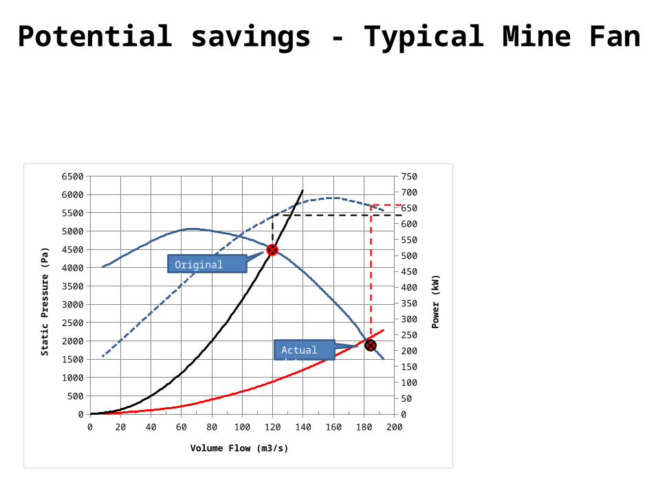
Actual dutyAir power = 360kWAbsorbed power = 660kWIn-efficiency lost = 300kW
Potential savings - Typical Mine Fan

• Efficiency achieved > 80% (from 60%) • Power Saved approximately 200 kW (per
fan)• Cost Saving R963 600 per annum (Based on
0.55c/kWh)
Potential savings - Typical Mine Fan

Theory – Basic Fan laws
1. Volume flow
2. Pressure
3. Power
Q – Volumetric flow rate (m3/s)P – Fan static pressure (Pa)kW – Absorbed power (kW)n – Fan operating speed (rpm)D – Impeller diameter (m)ρ – Air density (kg/m3)

Theory – Fan Efficiency
Low efficiency, due to losses
Best efficiency
Low efficiency, due to losses

Energy Savings Options
1. Inlet guide vanes (IGV’s)2. Speed control3. Impeller replacement
(1) Inlet Guide Vane (3) Impeller Replacement(2) Speed Control

Energy Savings Options- Inlet Guide Vanes

0 20 40 60 80 100 120 140 160 180 2000
500
1000
1500
2000
2500
3000
3500
4000
4500
5000
5500
6000
6500
0
50
100
150
200
250
300
350
400
450
500
550
600
650
700
750
Volume Flow (m3/s)
Stati
c Pre
ssur
e (P
a)
Pow
er (k
W)
Energy Savings Options - Inlet Guide Vanes
60° rpm
90°
Duty 1
Duty 2
• Power consumption is related to volume flow• Volume flow reduction of 10% - 15% is power savings of 22% -
25%

0 20 40 60 80 100 120 140 160 180 2000
500
1000
1500
2000
2500
3000
3500
4000
4500
5000
5500
6000
6500
0
50
100
150
200
250
300
350
400
450
500
550
600
650
700
750
Volume Flow (m3/s)
Stati
c Pre
ssur
e (P
a)
Pow
er (k
W)
Energy Savings Options - Inlet Guide Vanes
60° rpm
90°
Duty 1
Duty 2
By altering the IGV opening from 90° to 60° a saving of ±150kW can be achieved.

Energy Savings Options - Speed control• Fixed speed reduction gearbox• Variable frequency drives (VFD’s)

0 20 40 60 80 100 120 140 160 180 2000
500
1000
1500
2000
2500
3000
3500
4000
4500
5000
5500
6000
6500
0
50
100
150
200
250
300
350
400
450
500
550
600
650
700
750
Volume Flow (m3/s)
Stati
c Pre
ssur
e (P
a)
Pow
er (k
W)
Energy Savings Options - Speed control
600rpm745rpm
Duty 1
Duty 2
𝑄2
𝑄1
∝(𝑛2𝑛1 )𝑃2
𝑃1
∝(𝑛2𝑛1 )2

0 20 40 60 80 100 120 140 160 180 2000
500
1000
1500
2000
2500
3000
3500
4000
4500
5000
5500
6000
6500
0
50
100
150
200
250
300
350
400
450
500
550
600
650
700
750
Volume Flow (m3/s)
Stati
c Pre
ssur
e (P
a)
Pow
er (k
W)
Energy Savings Options - Speed control
600rpm745rpm
Duty 1
Duty 2
By adjusting the fan speed from 745 rpm to 600 rpm a saving of ±300kW can be achieved.
𝑄2
𝑄1
∝(𝑛2𝑛1 )𝑃2
𝑃1
∝(𝑛2𝑛1 )2

Original inefficient paddle wheel impeller
Replaced high efficiency backward inclined impeller
Photo courtesy of FläktWoods Fans Hermit Crab concept
Impeller Replacement – Example

Impeller Replacement – Design constraints
• No change to fan casing and civils • Existing impeller should be stored• Re-evaluate fan shaft and bearing selection• Vibration signature of the fan

Impeller Replacement – Design Parameters
Impeller diameter
Impeller exit angle
Impeller width
• Impeller diameter• Impeller width• Impeller exit angle• Impeller blade profile• Number of blades

0 20 40 60 80 100 120 140 160 180 2000
500
1000
1500
2000
2500
3000
3500
4000
4500
5000
5500
6000
6500
0
50
100
150
200
250
300
350
400
450
500
550
600
650
700
750
Volume Flow (m3/s)
Stati
c Pre
ssur
e (P
a)
Pow
er (k
W)
Impeller Replacement – Impeller diameter
16% Change in impeller diameter,
results in 58% decrease in
absorbed power
Original Duty Impeller diameter 2610mm
New DutyImpeller diameter 2200mm

Impeller Replacement - Impeller width • Distance between the backplate and the shroud • Width is directly proportional to the volumetric flow• Width defines the volume capabilities• If altered check inlet cone arrangement
Increase in power due to increased impeller
width.
0 20 40 60 80 100 120 140 160 180 200 220 240 2600
500
1000
1500
2000
2500
3000
3500
4000
4500
5000
5500
6000
6500
050100150200250300350400450500550600650700750800850900
Volume Flow (m3/s)
Stati
c Pre
ssur
e (P
a)
Pow
er (k
W)
Original DutyNew Duty

Impeller Replacement - Impeller exit angle• A larger blade exit angle reduces the exit shock losses• Backward curved impellers are typically more efficient than
radial type impellers• Changing the exit angle also impacts the static pressure

Impeller Replacement - Impeller blade profile
Blade aerodynamic profile:• Reducing drag and increasing lift• Reduced power at the same pressure and volume flow

Impeller Replacement - Number of blades• Increasing the number of blades increases the fan pressure• Increasing the blade numbers can result in secondary flow
losses and increased tip blockage

Impeller Replacement – Method of Analysis
1. Specify required static pressure and volume flow2. Start with a slightly decreased impeller diameter3. Increase impeller width by 100 mm to get a flatter head curve4. Decrease number of blades to get a reduced pressure curve5. Increase exit blade angle to get a reduced pressure curve6. Calculate efficiency using numerical methods (target eff. = 82%)7. Repeat steps 2 till 6 until desired curve is achieved
Finite Element Structural and fatigue analysis essential

Pres
sure
Flow
745 rpm
10°20°30°
Existing fan IGVsOld impeller/design resistanceOld impeller efficiencyNew resistanceNew impellerNew impeller efficiency
80%
70%75%
70%
75%
80%
745 rpm
Impeller Replacement – New fan curve
Original design duty @ 82%
NEW fan curve
Actual operating duty @ 65%
OLD fan curve
NEW fan duty @ 82%
Original mine system resistance
NEW mine system resistance

Impeller Replacement – Measured fan efficiency
Performance data:
• Volume flows 85 m3/s - 460 m3/s • Static pressures 1.6 kPa - 6.2 kPa.
• Old Fan efficiency 50% - 60% • New Fan Efficiency 75% - 80%.
• Possible Power Savings ~ 1 MWE
• Possible Cost Savings R5.6M pa (Megaflex)

Conclusion – Drop-in Impellers
• Drop-in impeller replacements are feasible on surface fans that are running at poor efficiency
• Payback period < 2 years • Saving R 5.6M per year – 1MWe (60% - 80%)• No significant technical or production risk


