A
SOLUTION
OF
POWER SYSTEM ANALYSIS – REE 603
A COURSE IN 6TH SEMESTER
OF
ELECTRICAL ENGINEERING / ELECTRICAL AND ELECTRONICS
ENGINEERING
DEPARTMENT OF ELECTRICAL ENGINEERING
SHAMBHUNATH INSTITUTE OF ENGINEERING AND TECHNOLOGY,
JHALWA, PRAYAGRAJ
Affiliated to
Dr. A.P.J. Abdul Kalam Technical University, Lucknow, Uttar Pradesh.
SHAMBHUNATH INSTITUTE OF ENGINEERING AND TECHNOLOGY
ELECTRICAL ENGINEERING DEPARTMENT
B.Tech: EE/EN, 6th
Semester –1st
Sessional Exam (2019-20)
Subject: Power System Analysis Subject Code: REE-603
SOLUTION SECTION – A
Q.1 Attempt all the parts of the following. (5x1=5)
a) What is per unit system?
Ans: - Per unit of any quantity is defined as the ratio of the quantity to its base value is
expressed as a Decimal
b) Write the boundary conditions of L-L and, L-G fault.
Ans: - Boundary conditions of L-L fault are-
Ia = 0, Ib = -IC, Vb - Vc = ZfIb
Boundary conditions of L-G fault are-
Ib = 0, Ic =0, Va=ZfIa
c) What are sequence impedance and sequence networks?
Ans: - The sequence impedances are the impedances offered by the devices for the like
Sequence component of the current.
The single phase equivalent circuit of a power system consists of impedances to
current of any one sequence is called sequence network.
d) Define one line diagram.
Ans: - A simplified diagram by omiting the completed circuit through the neutral and by
indicating the components of the power system by standard symbols rather than by
their equivalent.
e) Write the symmetrical components of three phase system..
Ans: - the symmetrical components of three phase system are-
i. Positive sequence components
ii. Negative sequence components.
iii. Zero sequence components.
SECTION-B
Q.2 Attempt any TWO parts of the following. (2x5=10)
a) A 200 MVA, 13.8 kV generator has a reactance of 0.85 p.u. and is generating 1.15 pu
voltage. Determine (a) the actual values of the line voltage, phase voltage and reactance,
and (b) the corresponding quantities to a new base of 500 MVA, 13.5 kV.
Solution:-
(a) Line voltage = 1.15 * 13.8 = 15.87 kV
Phase voltage = 1.15 * 13.8/√3 = 9.16 kV
.
Reactance = 0.85 * 13.82/200 = 0.809 Ω
(b) Line voltage = 1.15 * 13.8/13.5 = 1.176 pu
Phase voltage = 1.15 * (13.8/√3)/(13.5/√3) = 1.176 pu
Reactance = 0.85 * (13.8/13.5)2/(500/200) = 0.355 pu
b) Express the unsymmetrical components in terms of symmetrical components.
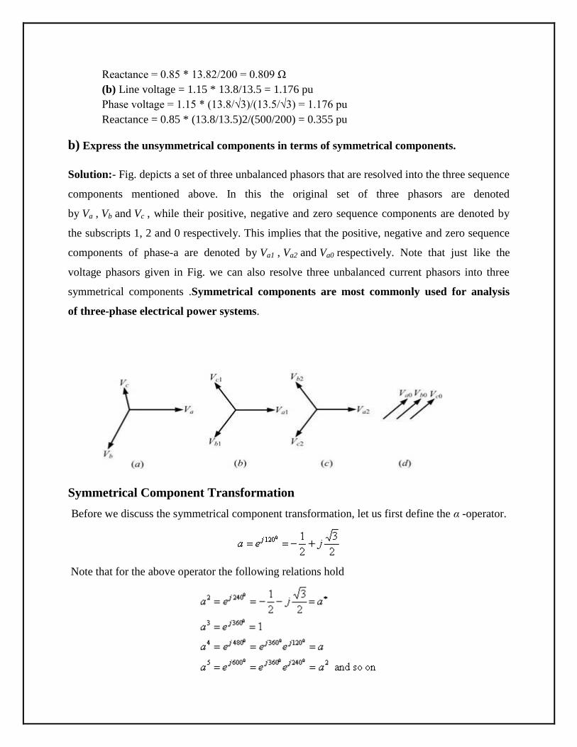
Solution:- Fig. depicts a set of three unbalanced phasors that are resolved into the three sequence
components mentioned above. In this the original set of three phasors are denoted
by Va , Vb and Vc , while their positive, negative and zero sequence components are denoted by
the subscripts 1, 2 and 0 respectively. This implies that the positive, negative and zero sequence
components of phase-a are denoted by Va1 , Va2 and Va0 respectively. Note that just like the
voltage phasors given in Fig. we can also resolve three unbalanced current phasors into three
symmetrical components .Symmetrical components are most commonly used for analysis
of three-phase electrical power systems.
Symmetrical Component Transformation
Before we discuss the symmetrical component transformation, let us first define the α -operator.
Note that for the above operator the following relations hold
Also note that we have
Using the a -operator we can write from Fig. (b)
Similarly from Fig. (c) we get
Finally from Fig. (d) we get
a set of three-phase voltages designated Va, Vb, and Vc is given as-
Therefore,
The symmetrical component transformation matrix is then given by
Defining the vectors V a012 and V abc as
we can write above as
where C is the symmetrical component transformation matrix and is given by
The original phasor components can be obtained from the inverse symmetrical component
transformation, i.e.,
Similarly we can also calculate a set of unbalanced current phasors as Iabc and their symmetrical
components as Ia012 ,
c) Derive the expression of power in terms of symmetrical components and also discuss the
reactance and impedance diagram of one-line diagram.
Solution:- The three-phase power in the original unbalanced system is given by
where I* is the complex conjugate of the vector I .
Now from this
and this equation
we get
we get
Therefore the power equation can be written as by putting the values of C-T
C-1*
Hence we say that the complex power is three times the summation of the complex power of the
three phase sequences.
Impedance Diagram
The impedance diagram on single-phase basis for use under balanced conditions can be easily
drawn from the SLD. The following assumptions are made in obtaining the impedance diagrams
Assumptions:
The single phase transformer equivalents are shown as ideals with impedances on
appropriate side (LV/HV),
The magnetizing reactance’s of transformers are negligible,
The generators are represented as constant voltage sources with series resistance or
reactance, -Models,
The transmission lines are approximated by their equivalent
The loads are assumed to be passive and are represented by a series branch of resistance
or reactance .
Since the balanced conditions are assumed, the neutral grounding impedances do not
appear in the impedance diagram.
Impedance diagram
Reactance Diagram
With some more additional and simplifying assumptions, the impedance diagram can be
simplified further to obtain the corresponding reactance diagram. The following are the
assumptions made.
Additional assumptions:
The resistance is often omitted during the fault analysis. This causes a very negligible
error since, resistances are negligible.
Loads are omitted.
Transmission line capacitances are ineffective.
Magnetizing currents of transformers are neglected.
Reactance Diagram
SECTION-C
Q.3 Attempt any ONE parts of the following. (1x5=5)
a) Derive the fault current expression for line to line fault.
Solution:- LINE-TO-LINE FAULT
The faulted segment for an L-L fault is shown in Fig. where it is assumed that the fault has
occurred at node k of the network. In this the phases b and c got shorted through the
impedance Zf . Since the system is unloaded before the occurrence of the fault we have
boundary condition
Also since phases b and c are shorted we have
Fig. Representation of L-L fault.
According to the symmetrical component transformation current equation can be written as
By put the value of boundary condition we get
From above result we can writ the value of current
Therefore no zero sequence current is injected into the network at bus k and hence the zero
sequence remains a dead network for an L-L fault. The positive and negative sequence currents
are negative of each other. the voltage at the faulted point
Again putting the values of sequence voltages values we get
Moreover since I fa0 = I fb0 = 0 and I fa1 = - I fb2 , we can write
Therefore combining above two eqution of current and voltages we get
The above voltage equation indicate that the positive and negative sequence networks are in
parallel. The sequence network is then as shown in Fig. From this network we get
Fig. Thevenin equivalent of an LL fault.
b) A 5 kVA 400/200 V, 50 Hz single phase transformer has primary and secondary leakage
reactance each of 2.5 Ω. Determine the total reactance in per unit.
Solution:-
Q.4 Attempt any ONE parts of the following. (1x5=5)
a) Derive the transient analysis of R-L series circuit.
Solution:-
b) Calculate the sequence components of the following balanced line-to-network voltages.
Q.5 Attempt any ONE parts of the following. (1x5=5)
a) Derive the expression for fault current in Line-to-Ground fault on an unloaded
generator in terms of symmetrical components.
Solution:- SINGLE-LINE-TO-GROUND FAULT
Let a Single Line to Ground fault has occurred at node k of a network. The faulted segment is
then as shown in Fig. where it is assumed that phase-a has touched the ground through an
impedance Zf . Since the system is unloaded before the occurrence of the fault we have boundary
conditions
Also the phase-a voltage at the fault point is given by
Fig. Representation of single line to ground fault.
According to the symmetrical component transformation current equation can be written as
The above equation can also be written as
This implies that the three sequence currents are in series for the 1-L-G fault. Let us denote the
zero, positive and negative sequence Thevenin impedance at the faulted point
as Z kk0, Z kk1 and Z kk2 respectively. Also since the Thevenin voltage at the faulted phase is Vf we
get three sequence circuits.
Then from current equation and above sequence component voltage we can write
Again since
The value of fault current can be written as
The Thevenin equivalent of the sequence network is shown in Fig
Fig Thevenin equivalent of the single line to ground fault
b) A 3-phase line operating at 11 KV and having a resistance of 1.5 ohm and reactance of 6
ohm is connected to a generating station bus bars through a 5 MVA step-up transformer
having reactance of 5%. The bus bars are supplied by a 12 MVA generator having 25%
reactance. Calculate the short circuit KVA fed into a symmetric fault (i) at the load end of
the transformer and (ii) at the h. v. terminals of the transformer. Assume base MVA 20.