37
Power System Protection Dr. Lionel R. Orama Exclusa, PE Week 1
Power System Protection
Dr. Lionel R. Orama Exclusa, PEWeek 1

Jan 18/2006 Copyright L.R. Orama 2006 2
Philosophy of Protective Relaying
Readings-Mason Chapter 1• Relay function• What exactly is a relay?• CT’s and PT’s• Abnormal conditions-faults• Desirable relay characteristics• Zones of protection
– Primary and backup protection
Copyright L.R. Orama 2006 3
Relay function
• Causes fast disconnection of equipment from power system during abnormal conditions– Minimizes damage– Minimizes effects on the system operation– Maximizes power transfer

Copyright L.R. Orama 2006 4
Relay function• Power transfer (from C.R. Mason page 13)
Copyright L.R. Orama 2006 5
What exactly is a relay?
• Measuring device-receives a signal from the Power System (PS) & determines if the condition is abnormal
• Control device-for abnormal conditions, it signals Circuit Breakers (CB) to disconnect equipment– It kind of “relays” a signal from the PS to the CB– Relay & CB is a system protection team– Fuses are simpler system

Copyright L.R. Orama 2006 6
What exactly is a relay?
Copyright L.R. Orama 2006 7
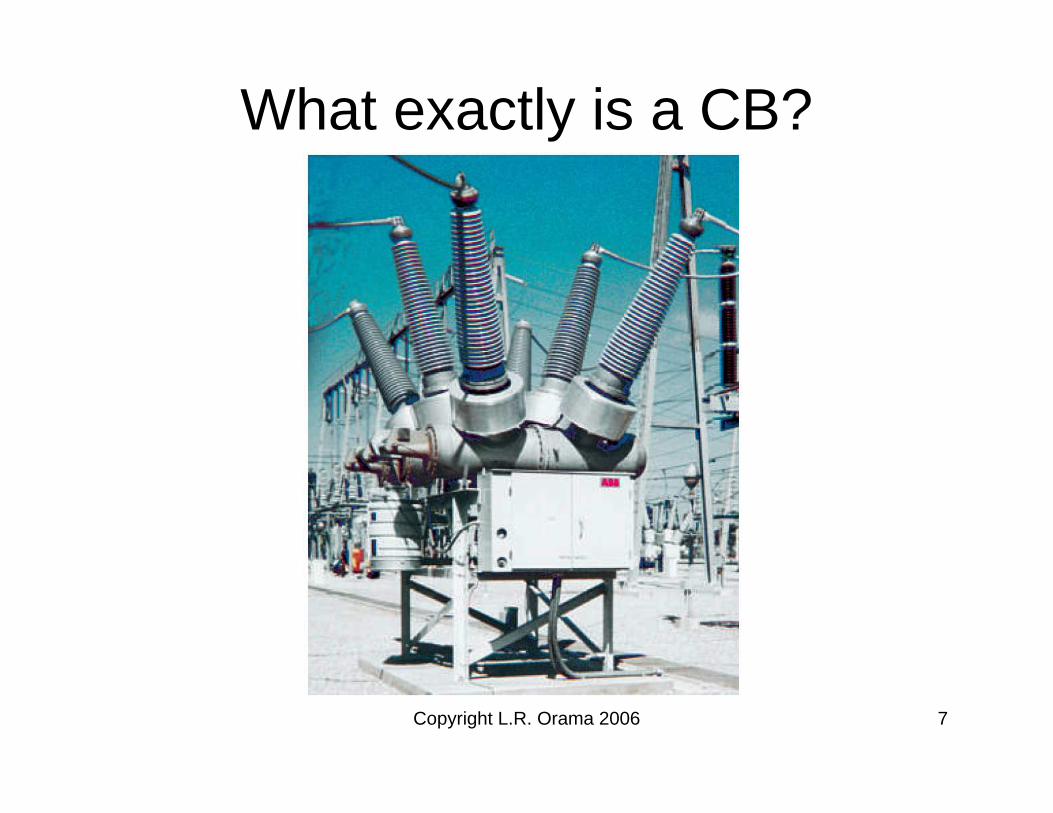
What exactly is a CB?

Copyright L.R. Orama 2006 8
What exactly is a relay?

Copyright L.R. Orama 2006 9
Current Transformers (CT’s)
• Device that produces current proportional to current in the power system conductor
• Ideal CT has current of:
• Rated ICT is aprox. 5A, typically (called CT secondary current)
CT
SYSCT N
II =

Copyright L.R. Orama 2006 10
Current Transformers (CT’s)
40020005
2001000:5
120600:5
80400:5
40200:5
20100:5
1050:5
TurnsCurrent
Common ratios
Polarity dot convention

Copyright L.R. Orama 2006 11
Potential Transformers (PT’s)
• Device that produces voltage proportional to voltage in the power system bus
• Ideal PT has voltage of:
• Rated VPT is aprox. 120V, typically (called PT secondary voltage)
1
2
N
NVV SYSPT =

Jan 20/2006 Copyright L.R. Orama 2006 12
Relaying Diagram
Copyright L.R. Orama 2006 13
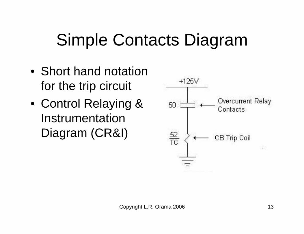
Simple Contacts Diagram
• Short hand notation for the trip circuit
• Control Relaying & Instrumentation Diagram (CR&I)
Copyright L.R. Orama 2006 14
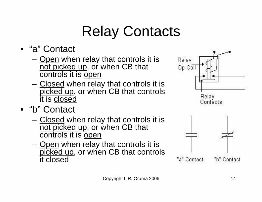
Relay Contacts• “a” Contact
– Open when relay that controls it is not picked up, or when CB that controls it is open
– Closed when relay that controls it is picked up, or when CB that controls it is closed
• “b” Contact– Closed when relay that controls it is
not picked up, or when CB that controls it is open
– Open when relay that controls it is picked up, or when CB that controls it closed

Copyright L.R. Orama 2006 15
Contacts• A relay is said to be picked up
when its:– Its “a” contacts are closedor– Its “b” contacts are open

Copyright L.R. Orama 2006 16
Faults (Short Circuits)
• Most common type of abnormal condition• Often Abnormally high currents flow IF>>IL• Flow of current in a path not intended for it• To interrupt IF, circuit must be opened• Relays often set based on calculated IF
Copyright L.R. Orama 2006 17
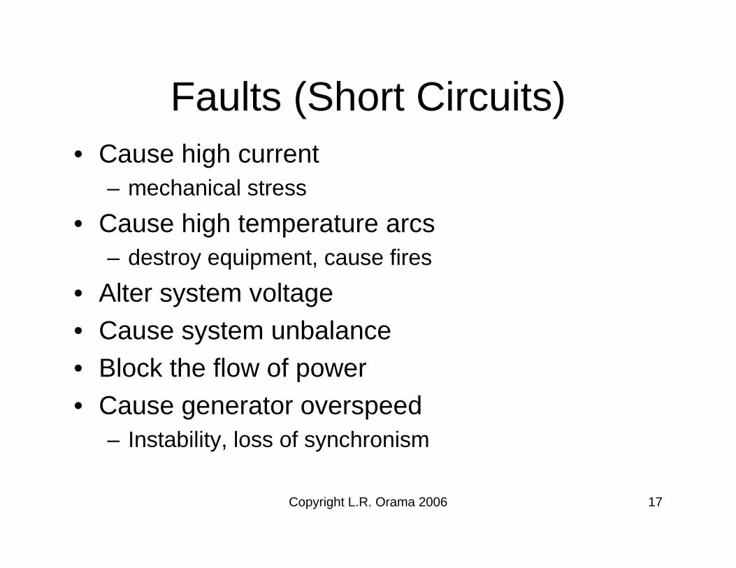
Faults (Short Circuits)• Cause high current
– mechanical stress
• Cause high temperature arcs– destroy equipment, cause fires
• Alter system voltage• Cause system unbalance• Block the flow of power• Cause generator overspeed
– Instability, loss of synchronism

Copyright L.R. Orama 2006 18
Fault Current Interruption
• No current flow when breakers open

Copyright L.R. Orama 2006 19
Desirable Relay Characteristics
• Speed (time to make decision 1/60sec)– Minimizes damage from current– Maximizes power transfer and stability
• Security– Relay should not cause CB to open during
normal conditions
• Dependability (reliability)– Relay should cause CB to open during
abnormal operation

Copyright L.R. Orama 2006 20
Desirable Relay Characteristics
• Sensitivity – Ability to detect all faults for the expected limiting
system and fault conditions• Selectivity
– Ability to discriminate between faults internal and external to its intended zone of protection

Copyright L.R. Orama 2006 21
Primary & Backup Protection
• Relays, CB’s, CT’s & PT’s located at substations
• Substation is a point of– Interconnection– Switching– Voltage
transformation

Jan 23/2006 Copyright L.R. Orama 2006 22
Primary & Backup Protection
• Every equipment should be protected by at least two independent protection systems
• Equipment– Lines, busses, transformers, generators
• Protection system– Primary and backup

Copyright L.R. Orama 2006 23
Primary Protection
• Primary– To do it, zones are drawn on the system’s
one-line diagram– Zones are defined by CT location and include
equipment & CB’s that isolate equipment

Copyright L.R. Orama 2006 24
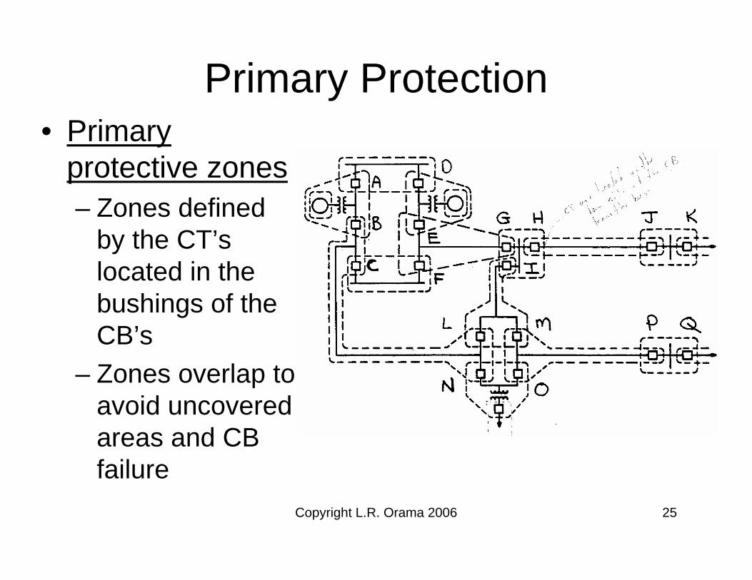
Primary Protection• Primary protective zones
– CB’s located in connection to each PS equipment
– Zones configured so the fault within the zone causes all CB’s in the zone to open
– CB’s open simultaneously & instantaneously (no intentional delay)
– If primary zone is successful, minimum effect on the system (power transfer ability)
Copyright L.R. Orama 2006 25
Primary Protection• Primary
protective zones– Zones defined
by the CT’slocated in the bushings of the CB’s
– Zones overlap to avoid uncovered areas and CB failure

Copyright L.R. Orama 2006 26
Primary & Backup Protection
Causes of Relay Failure• CT’s and circuits• PT’s and circuits• Loss of DC supply
– Short circuit– Open circuit– Failure of auxiliary switches
• Relay failure

Copyright L.R. Orama 2006 27
Primary & Backup Protection
Causes of CB failure• Loss of DC supply• Open trip coil• Short circuit trip coil• Mechanical failure• Failure of main contacts

Copyright L.R. Orama 2006 28
Backup Protection• Provided in case of:
– Primary relay failure– Circuit breaker failure
• Ideally primary & backup must be independent– Relay, CB’s, CT’s, PT’s– However, duplicity of CB’s is not practical & causes
other problems
• Backup is slower than primary• Opens more CB’s than necessary to clear a fault• Provides primary protection when primary
equipment is out of service

Copyright L.R. Orama 2006 29
Backup ProtectionTypes of backup protection• Remote backup
– Clears fault one substation away from where the failure has occured
• Local backup– Clears fault in the same substation where the
fault has occured

Copyright L.R. Orama 2006 30
Remote Backup
• CB’s P and O opens• CB M stay closed• Then B, C and I has to open • Load is lost in this case

Copyright L.R. Orama 2006 31
Remote Backup
• Trips more system than necessary to clear the fault
• Long backup times from 50-60 cycles (0.8-1.0 sec)
• Difficult to set remote relays• Initially, more economical• In the long run is more expensive

Copyright L.R. Orama 2006 32
Local Backup
• Primary relay op. & energizes timer
• If CB relays remain picked up & timer times out– Opens all CB’s on
the bus (trips all CB’s)

Copyright L.R. Orama 2006 33
Local Backup
• J opens• H closed• G and I opens• Load is operating
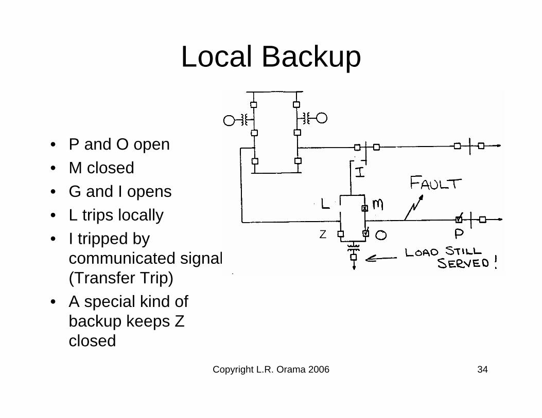
Copyright L.R. Orama 2006 34
Local Backup
• P and O open• M closed• G and I opens• L trips locally• I tripped by
communicated signal (Transfer Trip)
• A special kind of backup keeps Z closed
Copyright L.R. Orama 2006 35
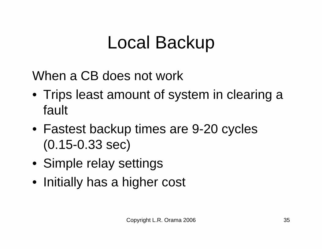
Local Backup
When a CB does not work• Trips least amount of system in clearing a
fault• Fastest backup times are 9-20 cycles
(0.15-0.33 sec)• Simple relay settings• Initially has a higher cost

Copyright L.R. Orama 2006 36
Remote vs. Local Backup
• Remote
• Local

Copyright L.R. Orama 2006 37
Remote vs. Local Backup
• Remote
• Local


