64
| Date post: | 15-Jul-2015 |
| Category: |
Engineering |
| Upload: | siswoyo-edo |
| View: | 469 times |
| Download: | 14 times |

Power System Protection
Fundamentals
Dr. Youssef A. Mobarak
2014
1

AGENDA
Why protection is needed
Principles and elements of the protection system
Basic protection schemes
Digital relay advantages and enhancements
2
Topic_1

DISTURBANCES: LIGHT OR SEVERE
The power system must maintain acceptable operation 24 hours a day
Voltage and frequency must stay within certain limits
Small disturbances
The control system can handle these
Example: variation in transformer or generator load
Severe disturbances require a protection system
They can jeopardize the entire power system
They cannot be overcome by a control system
3

POWER SYSTEM PROTECTION
Operation during severe disturbances:
System element protection
System protection
Automatic reclosing
Automatic transfer to alternate power supplies
Automatic synchronization
4

Generation-typically at 4-35kV
Transmission-typically at 230-765kV
Subtransmission-typically at 69-161kV
Receives power from transmission system and transforms
into subtransmission level
Receives power from subtransmission system and
transforms into primary feeder voltage
Distribution network-typically 2.4-69kV
Low voltage (service)-typically 120-600V
TYPICAL BULK POWER SYSTEM
5

PROTECTION ZONES
1. Generator or Generator-Transformer Units
2. Transformers
3. Buses
4. Lines (transmission and distribution)
5. Utilization equipment (motors, static loads, etc.)
6. Capacitor or reactor (when separately protected)
Unit Generator-Tx zone
Bus zone
Line zone
Bus zone
Transformer zoneTransformer zone
Bus zone
Generator
~
XFMR Bus Line Bus XFMR Bus Motor
Motor zone
6

WHAT INFO IS REQUIRED TO APPLY PROTECTION
1. One-line diagram of the system or area involved
2. Impedances and connections of power equipment, system frequency,
voltage level and phase sequence
3. Existing schemes
4. Operating procedures and practices affecting protection
5. Importance of protection required and maximum allowed clearance
times
6. System fault studies
7. Maximum load and system swing limits
8. CTs and VTs locations, connections and ratios
9. Future expansion expectance
10. Any special considerations for application. 11

C37.2: DEVICENUMBERS
Partial listing

ONE LINE DIAGRAM
Non-dimensioned diagram showing how pieces of electrical equipment are connected
Simplification of actual system
Equipment is shown as boxes, circles and other simple graphic symbols
Symbols should follow ANSI or IEC conventions
13
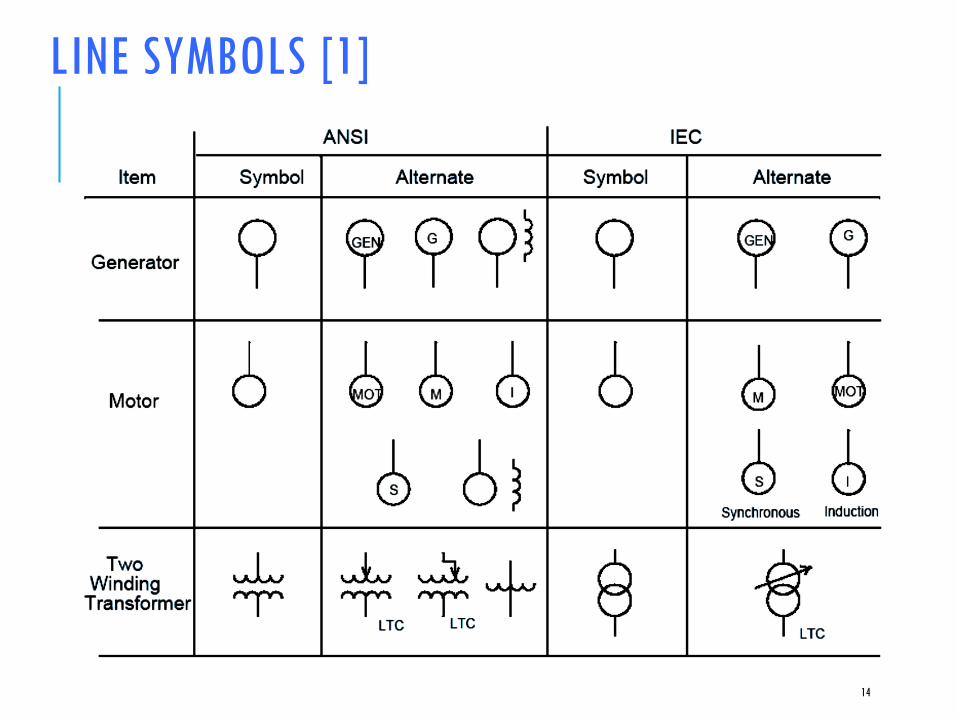
LINE SYMBOLS [1]
14

LINE SYMBOLS [2]
15
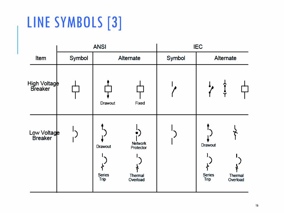
LINE SYMBOLS [3]
16

LINE SYMBOLS [4]
17

1-LINE [1]
18

PROTECTION SYSTEM
A series of devices whose main purpose is to
protect persons and primary electric power
equipment from the effects of faults
19
BLACKOUTS
Loss of service in a large area or population region
Hazard to human life
May result in enormous economic losses
Overreaction of the protection system
Bad design of the protection system
Characteristics Main Causes

SHORT CIRCUITS PRODUCE HIGH CURRENTS
FaultSubstation
a
b
c
I
IWire
Three-Phase Line
Thousands of Amps
20

ELECTRICAL EQUIPMENT THERMAL DAMAGE
I
t
In Imd
Damage Curve
Short-Circuit
Current
Damage
Time
Rated Value
21

MECHANICAL DAMAGE DURING SHORT CIRCUITS
Very destructive in busbars, isolators, supports, transformers, and machines
Damage is instantaneous
i1
i2
f1 f2
Rigid Conductors f1(t) = k i1(t) i2(t)
Mechanical
Forces
22
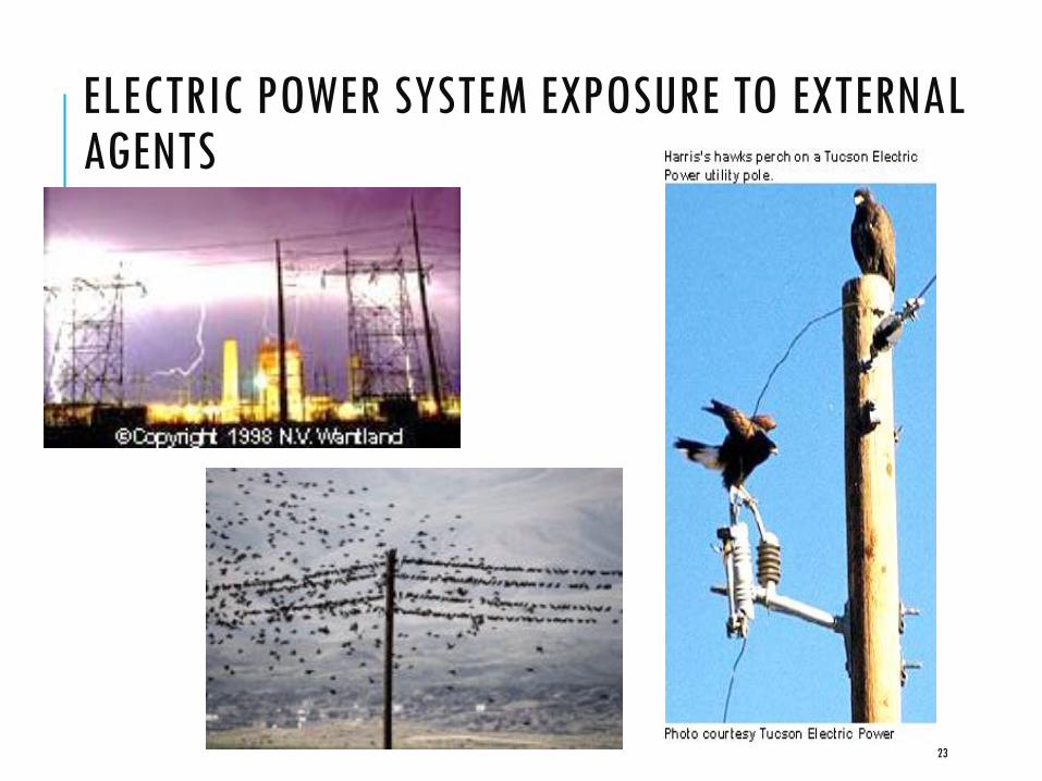
ELECTRIC POWER SYSTEM EXPOSURE TO EXTERNAL AGENTS
23
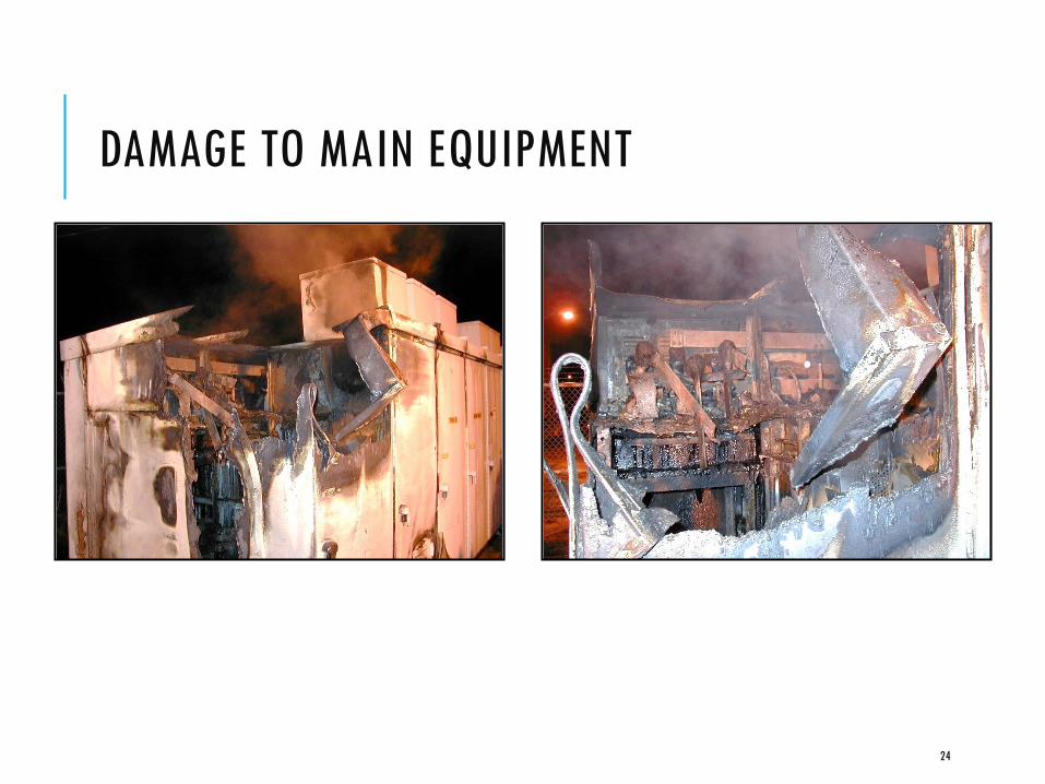
DAMAGE TO MAIN EQUIPMENT
24

THE FUSE
Fuse
Transformer
25

PROTECTION SYSTEM ELEMENTS
Protective relays
Circuit breakers
Current and voltage transducers
Communications channels
DC supply system
Control cables
26

THREE-PHASE DIAGRAM OF THE PROTECTION TEAM
CTs
VTs
Relay
CB
Control
Protected
Equipment
27
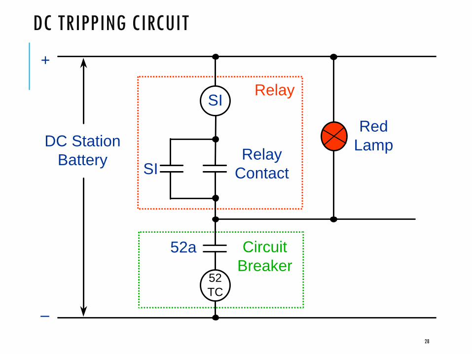
DC TRIPPING CIRCUIT
SI
52
TC
DC Station
Battery SI
Relay
Contact
Relay
Circuit
Breaker
52a
+
–
Red
Lamp
28

CIRCUIT BREAKERS
29
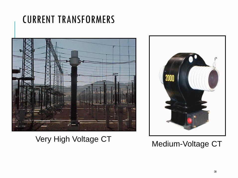
CURRENT TRANSFORMERS
Very High Voltage CTMedium-Voltage CT
30

VOLTAGE TRANSFORMERS
Medium Voltage
High Voltage
Note: Voltage transformers
are also known as potential
transformers
31

TYPICAL CT/VT CIRCUITS
Courtesy of Blackburn, Protective Relay: Principles and Applications
32

CT/VT CIRCUIT VS. CASING GROUND
Case ground made at IT location
Secondary circuit ground made at first point of use
Case
Secondary Circuit
Prevents shock exposure of personnel
Provides current carrying capability for the ground-fault current
Grounding includes design and construction of substation ground mat and CT and VT safety grounding
SUBSTATION TYPES
• Single Supply
• Multiple Supply
• Mobile Substations for emergencies
• Types are defined by number of transformers, buses,
breakers to provide adequate service for application
34

SWITCHGEAR DEFINED
Assemblies containing electrical switching, protection, metering and management devices
Used in three-phase, high-power industrial, commercial and utility applications
Covers a variety of actual uses, including motor control, distribution panels and outdoor switchyards
The term "switchgear" is plural, even when referring to a single switchgear assembly (never say, "switchgears")
May be a described in terms of use:
"the generator switchgear"
"the stamping line switchgear"
35
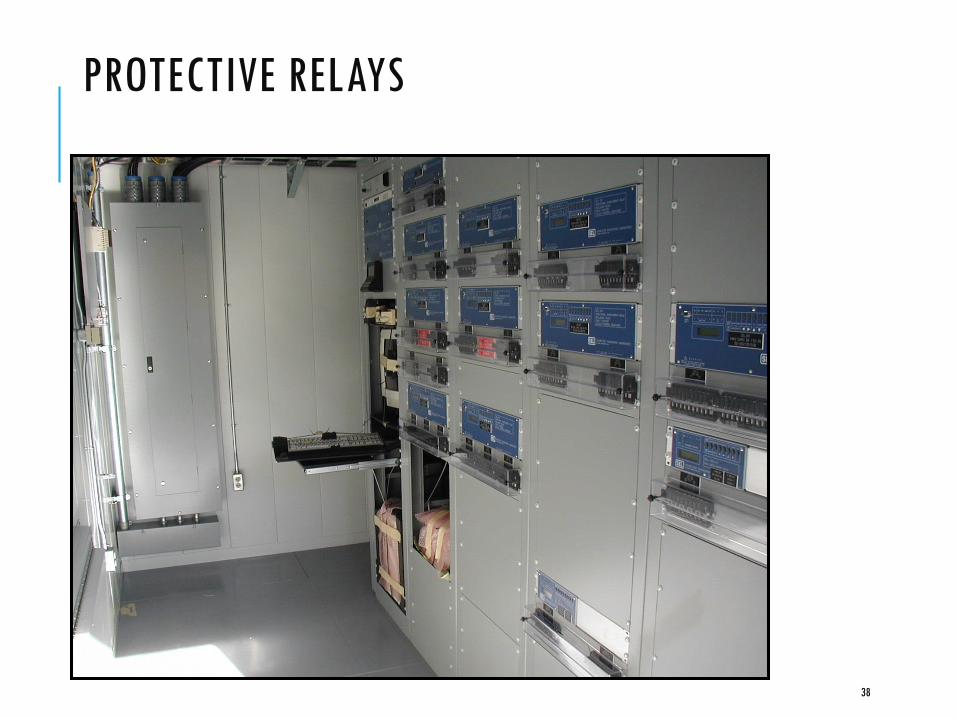
PROTECTIVE RELAYS
38

EXAMPLES OF RELAY PANELS
Old Electromechanical
Microprocessor-
Based Relay
39

HOW DO RELAYS DETECT FAULTS?
When a fault takes place, the current, voltage,frequency, and other electrical variables behave in apeculiar way. For example:
Current suddenly increases
Voltage suddenly decreases
Relays can measure the currents and the voltages anddetect that there is an overcurrent, or an undervoltage, ora combination of both
Many other detection principles determine the design ofprotective relays
40

MAIN PROTECTION REQUIREMENTS
Reliability
Dependability
Security
Selectivity
Speed
System stability
Equipment damage
Power quality
Sensitivity
High-impedance faults
Dispersed generation
41

PRIMARY PROTECTION
42

PRIMARY PROTECTION ZONE OVERLAPPING
Protection
Zone B
Protection
Zone A
To Zone B
Relays
To Zone A
Relays
52 Protection
Zone B
Protection
Zone A
To Zone B
Relays
To Zone A
Relays
52
43

BACKUP PROTECTION
A
C D
E
Breaker 5
Fails
1 2 5 6 11 12
T
3 4 7 8 9 10
B F
44

BALANCED VS. UNBALANCED CONDITIONS
Balanced System Unbalanced System
cI
aI
bI
aI
cI
bI
45
Typical Short-Circuit Type Distribution
Single-Phase-Ground: 70–80%
Phase-Phase-Ground: 17–10%
Phase-Phase: 10–8%
Three-Phase: 3–2%

DECOMPOSITION OF AN UNBALANCED SYSTEM
Positive-Sequence
Balanced Balanced
Negative-Sequence
1bI
1cI
1aI
2bI
2aI
2cI
0aI
0bI
0cI
aI
cI
bI
Zero-Sequence
Single-Phase46

CONTRIBUTION TO FAULTS
47

FAULT TYPES (SHUNT)
48
X
X
Z
Z
Z
G
BC
A
Short Circuit Calculation
Fault Types – Single Phase to Ground
X
X
Z
Z
Z
G
BC
A
Short Circuit Calculations
Fault Types – Line to Line
Z
Z
Z
G
BC
AX
X
X
Short Circuit Calculations
Fault Types – Three Phase

AC & DC CURRENT COMPONENTS OF FAULT CURRENT
49VARIATION OF CURRENT WITH TIME DURING A FAULT
VARIATION OF GENERATOR REACTANCEDURING A FAULT
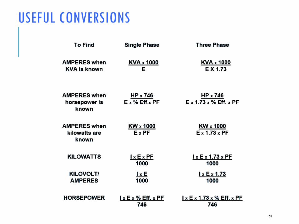
USEFUL CONVERSIONS
50

PER UNIT SYSTEM
Establish two base quantities:
Standard practice is to define
Base power – 3 phase
Base voltage – line to line
Other quantities derived
with basic power equations
51

SHORT CIRCUIT CALCULATIONSPER UNIT SYSTEM
Per Unit Value = Actual QuantityBase Quantity
Vpu = Vactual
Vbase
Ipu = Iactual
Ibase
Zpu = Zactual
Zbase
52
3 x kV L-L base
I base =x 1000MVAbase
Z base =kV2
L-L base
MVAbase
Zpu2 =Zpu1 x kV 2base1 x MVAbase2
kV 2base2 MVAbase1
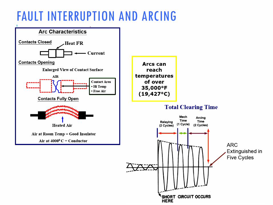
FAULT INTERRUPTION AND ARCING
57

POWER LINE PROTECTION PRINCIPLES
Overcurrent (50, 51, 50N, 51N)
Directional Overcurrent (67, 67N)
Distance (21, 21N)
Differential (87)
58
tRelay
Operation
Time
I
Fault Load
Radial Line
APPLICATION OF INVERSE -TYPE RELAYS

INVERSE-TIME RELAY COORDINATION
59
tRelay
Operation
Time
I
Fault Load
Radial Line
Distance
Distance
t
I
T T T
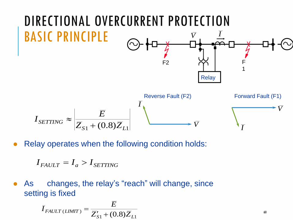
DIRECTIONAL OVERCURRENT PROTECTIONBASIC PRINCIPLE
F2
Relay
F
1
Forward Fault (F1)Reverse Fault (F2)
V
IV
I
IV
60
11 )8.0( LS
SETTINGZZ
EI
11
)()8.0( LS
LIMITFAULTZZ
EI
Relay operates when the following condition holds:
SETTINGaFAULT III
As changes, the relay’s “reach” will change, since
setting is fixed

DISTANCE RELAY PRINCIPLE
L
Three-Phase
Solid Fault
d
Radial
Line2
1
Suppose Relay Is Designed to Operate When:
||||)8.0(|| 1 aLa IZV
cba III ,,
cba VVV ,,
61
21
22rZXR
R
X Plain Impedance Relay
Operation Zone
Zr1
Radius Zr11rZZ
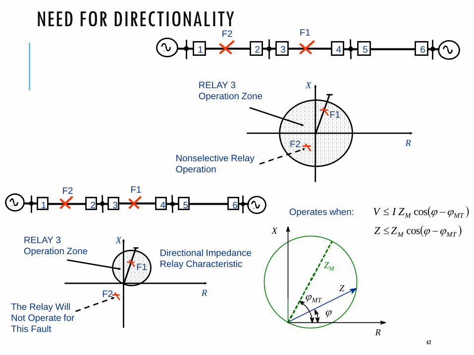
NEED FOR DIRECTIONALITYF1
1 2 3 4 5 6
F2
R
XRELAY 3
Operation Zone
F1
F2
Nonselective Relay
Operation
62
1 2 3 4 5 6
F1F2
R
XRELAY 3
Operation Zone
F1
F2
The Relay Will
Not Operate for
This Fault
Directional Impedance
Relay Characteristic
MTMZZ cos
ZM
Z
R
X
MT
MTMZIV cosOperates when:

THREE-ZONE DISTANCE PROTECTION
1 2 3 4 5 6
Zone 1
Zone 2
Zone 3
Time
Time
Zone 1 Is Instantaneous
63
X
RA
B
C
D

DISTANCE PROTECTION SUMMARYCurrent and voltage information
Phase elements: more sensitive than 67 elements
Ground elements: less sensitive than 67N elements
Application: looped and parallel lines
64
Communications
Channel
Exchange of logic information
on relay status
RL
Relays Relays
T
R
R
T
LI RI

PERMISSIVE OVERREACHING TRANSFER TRIP
1 2 3 4 5 6
FWD
FWD
Bus A Bus B
65
1 2 3 4 5 6
FWD
FWD
RVS
RVS
Bus A Bus B

DIFFERENTIAL PROTECTION PRINCIPLE
No Relay Operation if CTs Are Considered Ideal
External
Fault
IDIF = 0
CT CT
50
Balanced CT Ratio
Protected
Equipment
66
Internal
Fault
IDIF > ISETTING
CTR CTR
50
Relay Operates
Protected
Equipment

PROBLEM OF UNEQUAL CT PERFORMANCE
False differential current can occur if a CT saturates during a through-fault
Use some measure of through-current to desensitize the relay when high currents are present
External
Fault
Protected
Equipment
IDIF 0
CT CT
50
67

POSSIBLE SCHEME – PERCENTAGE DIFFERENTIAL PROTECTION PRINCIPLE
Protected
Equipment
ĪRĪS
CTR CTR
Compares:
Relay
(87)
OP S RI I I
| | | |
2
S RRT
I Ik I k
ĪRPĪSP
68

DIFFERENTIAL PROTECTION APPLICATIONS
Bus protection
Transformer protection
Generator protection
Line protection
Large motor protection
Reactor protection
Capacitor bank protection
Compound equipment protection
69
DIFFERENTIAL PROTECTIONSUMMARY
The overcurrent differential scheme is simple and economical, but it does not respond well to unequal current transformer performance
The percentage differential scheme responds better to CT saturation
Percentage differential protection can be analyzed in the relay and the alpha plane
Differential protection is the best alternative selectivity/speed with present technology
70

MULTIPLE INPUT DIFFERENTIAL SCHEMESEXAMPLES
Differential Protection Zone
Bus Differential: Several Inputs
ĪRPĪSP
OP
ĪT
I1 I2 I3 I4
Three-Winding Transformer
Differential: Three Inputs
71

ADVANTAGES OF DIGITAL RELAYS
Multifunctional
Compatibility with
digital integrated
systems
Low maintenance
(self-supervision)
Highly sensitive,
secure, and
selective
AdaptiveHighly reliable
(self-supervision)
Reduced burden
on
CTs and VTs
Programmable
VersatileLow Cost
72

A GOOD DAY IN SYSTEM PROTECTION……
CTs and VTs bring electrical info to relays
Relays sense current and voltage and declare fault
Relays send signals through control circuits to circuit breakers
Circuit breaker(s) correctly trip
73
A BAD DAY IN SYSTEM PROTECTION……
CTs or VTs are shorted, opened, or their wiring is
Relays do not declare fault due to setting errors, faulty relay, CT saturation
Control wires cut or batteries dead so no signal is sent from relay to circuit breaker
Circuit breakers do not have power, burnt trip coil or otherwise fail to trip

PROTECTION PERFORMANCE STATISTICSCorrect and desired: 92.2%
Correct but undesired: 5.3%
Incorrect: 2.1%
Fail to trip: 0.4%
74
THE FUTURE
Improvements in computer-based protection
Highly reliable and viable communication systems (satellite, optical fiber, etc.)
Integration of control, command, protection, and communication
Improvements to human-machine interface
Much more


