60
POWER SYSTEM STABILITY ENHANCEMENT BY USING SSSC DEPT OF EEE GKCE, SULLURUPETA Page 1 Chapter 1 INTRODUCTION
| Date post: | 21-Oct-2015 |
| Category: |
Documents |
| Upload: | sai-bhargav-veerabathini |
| View: | 183 times |
| Download: | 0 times |

POWER SYSTEM STABILITY ENHANCEMENT BY USING SSSC DEPT OF EEE
GKCE, SULLURUPETA Page 1
Chapter 1
INTRODUCTION

POWER SYSTEM STABILITY ENHANCEMENT BY USING SSSC DEPT OF EEE
GKCE, SULLURUPETA Page 2
1. INTRODUCTION
Nowadays, the need for flexible and fast power flow control in the
transmission system is anticipated to increase in the future in view of utility deregulation
and power wheeling requirement. The utilities need to operate their power transmission
system much more effectively, increasing their utilization degree. Reducing the effective
reactance of lines by series compensation is a direct approach to increase transmission
capability. However, power transfer capability of long transmission lines is limited by
stability considerations. Because of the power electronic switching capabilities in terms
of control and high speed, more advantages have been done in FACTS devices areas and
presence of these devices in transient stability during transient faults resulting in
improvement in power system stability. This paper investigates the static synchronous
series compensator (SSSC) FACTS controller performance in terms of stability
improvements.
A Static Synchronous Series Compensator (SSSC) is a member of FACTS
family which is connected in series with a power system. It consists of a solid state
voltage source converter (VSC) which generates a controllable alternating current voltage
at fundamental frequency. When the injected voltage is kept in quadrature with the line
current, it can emulate as inductive or capacitive reactance so as to influence the power
flow through the transmission line. While the primary purpose of a SSSC is to control
power flow in steady state, it can also improve transient stability of a power system.

POWER SYSTEM STABILITY ENHANCEMENT BY USING SSSC DEPT OF EEE
GKCE, SULLURUPETA Page 3
CHAPTER 2
FACTS

POWER SYSTEM STABILITY ENHANCEMENT BY USING SSSC DEPT OF EEE
GKCE, SULLURUPETA Page 4
2. FACTS
2.1 Introduction
With the history of more than three decades and widespread research and development,
FACTS controllers are now considered a proven and mature technology. The operational
flexibility and controllability that FACTS has to offer will be one of the most important
tools for the system operator in the changing utility environment. In view of the various
power system limits, FACTS provides the most reliable and efficient solution. The high
initial cost has been the barrier to its deployment, which highlight the need to device
proper tools and methods for quantifying the benefits that can be derived from use of
FACTS.
Why power flow control is important
For economic reasons most if not all of the worlds electric power supply are widely
Interconnected, involving interconnections Inside utilities own territories which extend
To inter-utility interconnections and then t o Inter - regional’s .We need these
interconnections because apart From delivery, the purpose of the transmission Network is
t o pool power plants and load Centers, in order to minimize the number of Power
generation sources needed, taking Advantage of diversity of loads, availability Of sources
and fuel in order to supply the Load a t a required reliability . If we just had radial lines,
we would need many more Generation resources to serve the load with the same
reliability. If you look a tit that Way, transmission is an alternative to a new Generation
resource. Less transmission Capability means that more generation Resources would be
required regardless of whether we have large or small power plants. Often as power
transfers grow, the power system becomes increasingly more complex to operate and the
system can become more insecure with large power flows with inadequate control and
inability to utilize the full potential of transmission interconnections.
FACTS – What and why?
FACTS are the acronym for Flexible AC Transmission Systems and refer to a group of
resources used to overcome certain limitations in the static and dynamic transmission

POWER SYSTEM STABILITY ENHANCEMENT BY USING SSSC DEPT OF EEE
GKCE, SULLURUPETA Page 5
capacity of electrical networks.The IEEE defines FACTS as “alternating current
transmission systems incorporating power-electronics based and other static controllers to
enhance controllability and power transfer capability. The main purpose of these systems
is to supply the network as quickly as possible with inductive or capacitive reactive
power that is adapted to its particular requirements, while also improving transmission
quality and the efficiency of the power transmission System”.
FACTS for supplying power –Now and in the future
The inevitable globalization and liberalization of energy markets associated with
growing deregulation and privatization are increasingly resulting in bottlenecks,
uncontrolled load flows, instabilities, and even power transmission failures. Power
supplies are increasingly dependent on distributed power plants with higher voltage
levels, and transport to large load centers over what are often long distances. This type of
power transmission must be implemented safely and cost effectively
With a view to the future. Implementing new transmission systems and
components is a long-term strategy for meeting these challenges. Over the short and
medium term, modern transmission technologies can be employed at comparatively little
expense to rectify or minimize bottlenecks and substantially improve the quality of
supply. Often, this makes it possible to postpone investing in new plants and, as a result,
to achieve critical advantages over the competition – especially important in de-regulated
energy markets in which power supply companies are subject to extreme conditions.
FACTS provide
1. Fast voltage regulation
2. Increased power transfer over long AC lines
3. Damping of active power oscillations
4. Load flow control in power system
5. Balance reactive power

POWER SYSTEM STABILITY ENHANCEMENT BY USING SSSC DEPT OF EEE
GKCE, SULLURUPETA Page 6
This means that with FACTS, power companies will be able to better utilize their existing
transmission networks, substantially increase the availability and reliability of their line
networks, and improve both dynamic and transient network stability while ensuring a
better quality of supply.
2.2 FACTS BASIC TERMS AND DEFINITION:-
The definitions presented in the following are divided into basic definitions and
Definitions of Controllers that serve specific function(s). The given categorization is the
Result of extensive discussions and compromises.
Basic Definitions:-
1. Flexibility of Electric Power Transmission:-
The ability to accommodate changes in the electric transmission system or operating
Conditions while maintaining sufficient steady state and transient margins.
2. Flexible AC Transmission System:-
Alternating current transmission systems incorporating power electronic-based and Other
static controllers to enhance controllability and increase power transfer capability.
3. FACTS Controller:-
A power electronic-based system and other static equipment that provide control of one
or more AC transmission system parameters.
4. FACTS Controllers Definitions:-
The definitions presented in the following are organized according to their respective
connection to the controlled ac transmission system.
(A) Shunt Connected Controllers:-
1. Battery Energy Storage System (BESS):- A chemical-based energy storage system
using shunt connected, voltage sourced converters capable of rapidly adjusting the
amount of energy which is supplied to or absorbed from an ac system.
2. Static Synchronous Compensator (SSC or STATCOM):- A static synchronous
generator operated as a shunt-connected static var compensator whose capacitive or
inductive output current can be controlled independent of the ac system voltage.
3. Static Condenser (STATCON):- This term is deprecated in favor of the Static
Synchronous Compensator (SSC or STATCOM

POWER SYSTEM STABILITY ENHANCEMENT BY USING SSSC DEPT OF EEE
GKCE, SULLURUPETA Page 7
4. Static Synchronous Generator (SSG):- A static, self-commutated switching power
converter supplied from an appropriate electric energy source and operated to produce a
set of adjustable multi-phase output voltages, which may be coupled to an ac power
system for the purpose of exchanging independently controllable real and reactive power.
5. Static Var Compensator (SVC):- A shunt-connected static var generator or absorber
whose output is adjusted to exchange capacitive or inductive current so as to maintain or
control specific parameters of the electrical power system (typically bus voltage).
6. Static Var Generator or Absorber (SVG):- A static electrical device, equipment, or
system that is capable of drawing controlled capacitive and/or inductive current from an
electrical power system and thereby generating or absorbing reactive power. Generally
considered to consist of shunt connected, thyristor-controlled reactor(s) and/or thyristor-
switched capacitors.
7. Static Var System (SVS):- A combination of different static and mechanically-
switched var compensators whose outputs are coordinated.
8. Superconducting Magnetic Energy Storage (SMES): - A Superconducting
electromagnetic energy storage device containing electronic converters that rapidly
injects and/or absorbs real and/or reactive power or dynamically controls power flow in
an ac system
9. Thyristor Controlled Braking Resistor (TCBR):- A shunt-connected, thyristor-
switched resistor, which is controlled to aid stabilization of a power system or to
minimize power acceleration of a generating unit during a disturbance.
10. Thyristor Controlled Reactor (TCR):- A shunt-connected, thyristor-controlled
inductor whose effective reactance is varied in a continuous manner by partial conduction
control of the thyristor valve.
11. Thyristor Switched Capacitor (TSC):- A shunt-connected, thyristor-switched
capacitor whose effective reactance is varied in a stepwise manner by full- or zero
conduction operation of the thyristor valve.
12. Thyristor Switched Reactor (TSR):- A shunt-connected, thyristor-switched
inductor whose effective reactance is varied in a stepwise manner by full- or zero
conduction operation of the thyristor valve.

POWER SYSTEM STABILITY ENHANCEMENT BY USING SSSC DEPT OF EEE
GKCE, SULLURUPETA Page 8
13. Var Compensating System (VCS):- A combination of different static and rotating
var compensators whose outputs are coordinated.
(B) Series Connected Controllers:-
1. Static Synchronous Series Compensator (SSSC):- A static, synchronous generator
operated without an external electric energy source as a series compensator whose output
voltage is in quadrature with, and controllable independently of, the line current for the
purpose of increasing or decreasing the overall reactive voltage drop across the line and
thereby controlling the transmitted electric power . The S3C may include transiently
rated energy storage or energy absorbing devices to enhance the dynamic behavior of the
power system by additional temporary real power compensation, to increase or decrease
momentarily, the overall real (resistive) voltage drop across the line.
2. Thyristor controlled Series Capacitor (TCSC):- A capacitive reactance compensator
which consists of a series capacitor bank shunted by thyristor controlled reactor in order
to provide a smoothly variable series capacitive reactance.
3. Thyristor Controlled Series compensation: - An impedance compensator which is
applied in series on an ac transmission system to provide smooth control of series
reactance.
3. Thyristor Controlled Series Reactor (TCSR):- An inductive reactance compensator
which consists of a series reactor shunted by a thyristor controlled reactor in order to
provide a smoothly variable series inductive reactance.
4. Thyristor Switched Series Capacitor (TCSC):- A capacitive reactance compensator
which consists of a series capacitor bank shunted by a thyristor switched reactor to
provide a stepwise control of series capacitive reactance.
5. Thyristor Switched Series Compensation (TSSC):- An impedance compensator
which is applied in series on an ac transmission system to provide a step-wise control of
series reactance.
6. Thyristor Switched Series Reactor (TSSR):-An inductive reactance compensator
which consists of series reactor shunted by thyristor switched reactor in order to provide a
stepwise control of series inductive reactance.

POWER SYSTEM STABILITY ENHANCEMENT BY USING SSSC DEPT OF EEE
GKCE, SULLURUPETA Page 9
(C) Combined Shunt and Series Connected Controllers:-
1. Interphase Power Controller (IPC):- A series-connected controller of active and
reactive power consisting, in each phase, of inductive and capacitive branches subjected
to separately phase-shifted voltages. The active and reactive power can be set
independently by adjusting the phase shifts and/or the branch impedances, using
mechanical or electronic switches. In the particular case where the inductive and
capacitive impedances form a conjugate pair, each terminal of the IPC is a passive
current source dependent on the voltage at the other terminal.
2. Thyristor Controlled Phase Shifting Transformer (TCPST):- A phase-shifting
transformer, adjusted by thyristor switches to provide a rapidly variable phase angle.
3. Unified Power Flow Controller (UPFC):- A combination of a static synchronous
compensator (STATCOM) and a static synchronous series compensator (S3C) which are
coupled via a common dc link, to allow bi-directional flow of real power between the
series output terminals of the S3C and the shunt output terminals of the STATCOM, and
are controlled to provide concurrent real and reactive series line compensation without an
external electric energy source. The UPFC, by means of angularly unconstrained series
voltage injection, is able to control, concurrently or selectively, the transmission line
voltage, impedance, and angle or, alternatively, the real and reactive power flow in the
line. The UPFC may also provide independently controllable shunt reactive
compensation.
Other Controllers:-
Thyristor Controlled Voltage Limiter (TCVL):- A thyristor-switched metal-oxide
varistor (MOV) used to limit the voltage across its terminals during transient conditions.
2.3 PRESENT STATUS OF FACTS CONTROLLERS :-
FACTS Controllers are currently in various stages of maturity. Some, such as
SVCs, STATCOM and TCSCs, are commercially available. Others are either in the
development or demonstration stages.

POWER SYSTEM STABILITY ENHANCEMENT BY USING SSSC DEPT OF EEE
GKCE, SULLURUPETA Page 10
Commercially Available FACTS Controllers:-The FACTS Controllers for which
commercial or demonstration projects exist include:
1. Static Var Compensator (SVC):- SVCs have been in use since the early 1960s. The
SVC application for transmission voltage control began in the late 1970s. Since that time,
many SVCs have been applied worldwide for voltage control and, in some cases for
stability enhancement.
2. Thyristor Switched / Controlled Series Capacitor (TSSC/TCSC):- Since 1991 there
have been three installations, in the United States of America (USA), using thyristor
switches to obtain a controllable series capacitive compensation. The first installation was
essentially experimental in nature, testing the hardware of thyristor switched series
capacitor (TSSC). A thyristor valve was applied across one phase of a capacitor module
on a series capacitive compensated 345 KV transmission line Kanawa River - Matt Funk
line at Kanawa River Substation in West Virginia. The second installation was a thyristor
controlled series capacitor (TCSC). It consists of a fixed capacitor shunted by a thyristor
controlled reactor, providing continuously controlled series capacitive compensation. It
was installed in a 300 km, 230 KV transmission line at the Kayenta Substation in
Arizona. The functions of this installation are to increase power transfers to the line’s
thermal limit and evaluate the TCSC ability to control power flow, line impedance, damp
electromechanical power oscillations, and mitigate Sub synchronous Resonance The third
installation, at the Slat substation in Oregon, is also a TCSC . The Slat TCSC is
comprised of six identical thyristor controlled capacitor modules connected in series.
3. Static Synchronous Compensator (STATCOM):-
The most recent STATCOM installation is a ±100 MVAR STATCOM which is installed
in November 1995 at Sullivan (500 KV / 161 KV) substation in Johnson City, Tennessee.
In 1991 an 80 MVAR was installed at the Inuyama Switching Station in Japan. In
operation the 100 MVAR STATCOM will provide voltage control to the 161 KV bus
voltages during daily buildup to minimize the activation of the on load tap changer of the
500 KV / 161 KV transformer. Furthermore, the STATCOM will provide adequate
voltage support to the 161 KV and 500 KV buses during light and peak load conditions.

POWER SYSTEM STABILITY ENHANCEMENT BY USING SSSC DEPT OF EEE
GKCE, SULLURUPETA Page 11
2.4 FACTS Controllers Currently Under Development
Unified Power Flow Controller (UPFC):- The first large-scale UPFC will consist of a
shunt voltage sourced inverter (STATCOM) rated at 2 160 MVA to provide 2 150
MVAR reactive power support and 50 MW real power through the DC link required in
full UPFC mode of operation. The series voltage sourced inverter is rated 160 MVA to
provide phase shifting and/or series compensation. Both the STATCOM and series
subsystem will consist of a 160 MVA voltage sourced, multi-pulse, harmonic neutralized
GTO inverter and magnetic interface. The UPFC will be installed on 138 KV
transmission line at Inez substation in Kentucky. The installation is planned to be
completed by the end of 1997.
Future FACTS Controllers:-FACTS Controllers which are expected to be available in
the foreseeable future include:
Thyristor Controlled Phase Shifting transformer (TCPST).
Static Synchronous Series Compensator (SSSC).
Interphase power controller (IPC).
General Description:-
The large interconnected transmission networks (made up of predominantly
overhead transmission lines) are susceptible to faults caused by lightning discharges and
decrease in insulation clearances by undergrowth. The power flow in a transmission line
is determined by Kirchhoff's laws for specified power injections (both active and
reactive) at various nodes. While the loads in a power system vary by the time of the day
in general, they are also subject to variations caused by the weather (ambient
temperature) and other unpredictable factors. The generation pattern in a deregulated
environment also tends to be variable (and hence less predictable). Thus, the power flow
in a transmission line can vary even under normal, steady state conditions.
The occurrence of a contingency (due to the tripping of a line, generator) can
result in a sudden increase/decrease in the power flow. This can result in overloading of
some lines and consequent threat to system secure a major disturbance can also result in
the swinging of generator rotors which contribute to power swings in transmission lines.
It is possible that the system is subjected to transient instability and cascading outages as
individual components (lines and generators) trip due to the action of protective relays. If

POWER SYSTEM STABILITY ENHANCEMENT BY USING SSSC DEPT OF EEE
GKCE, SULLURUPETA Page 12
the system is operating close to the boundary of the small signal stability region, even a
small disturbance can lead to large power swings and blackouts. The increase in the
loading of the transmission lines sometimes can lead to voltage collapse due to the
shortage of reactive power delivered at the load centers. This is due to the increased
consumption of the reactive power in the transmission network and the characteristics of
the load (such as induction motors supplying constant torque). The factors mentioned in
the previous paragraphs point to the problems faced in maintaining economic and secure
operation of large interconnected systems.
The problems are eased if sufficient margins (in power transfer) can be
maintained. This is not feasible due to the difficulties in the expansion of the transmission
network caused by economic and environmental reasons. The required safe operating
margin can be substantially reduced by the introduction of fast dynamic control over
reactive and active power by high power electronic controllers. This can make the AC
transmission network “flexible” to adapt to the changing conditions caused by
contingencies and load variations. Flexible AC Transmission System (FACTS) is defined
as `Alternating current transmission systems incorporating power electronic-based and
other static controllers to enhance controllability and increase power transfer capability’.
The FACTS controller is defined as a power electronic based system and other static
equipment that provide control of one or more AC transmission system parameters.
The FACTS controllers can be classified as
1. Shunt connected controllers
2. Series connected controllers
3. Combined series-series controllers
4. Combined shunt-series controllers
Depending on the power electronic devices used in the control, the FACTS controllers
can be classified as
(A) Variable impedance type
(B) Voltage Source Converter (VSC).
The variable impedance type controllers include:
(i) Static Var Compensator (SVC), (shunt connected)

POWER SYSTEM STABILITY ENHANCEMENT BY USING SSSC DEPT OF EEE
GKCE, SULLURUPETA Page 13
(ii) Thyristor Controlled Series Capacitor or compensator (TCSC), (series
connected)
(iii) Thyristor Controlled Phase Shifting Transformer (TCPST) of Static PST
(combined shunt and series)
The VSC based FACTS controllers are:
(i) Static synchronous Compensator (STATCOM) (shunt connected)
(ii) Static Synchronous Series Compensator (SSSC) (series connected)
(iii) Interline Power Flow Controller (IPFC) (combined series-series)
(iv) Unified Power Flow Controller (UPFC) (combined shunt-series)
Some of the special purpose FACTS controllers are
(a) Thyristor Controller Braking Resistor (TCBR)
(b) Thyristor Controlled Voltage Limiter (TCVL)
(c) Thyristor Controlled Voltage Regulator (TCVR)
(d) Interphase Power Controller (IPC)
(e) NGH-SSR damping
The FACTS controllers based on VSC have several advantages over the
variable impedance type. For example, a STATCOM is much more compact than a SVC
for similar rating and is technically superior. It can supply required reactive current even
at low values of the bus voltage and can be designed to have in built short term overload
capability. Also, a STATCOM can supply active power if it has an energy source or large
energy storage at its DC terminals. The only drawback with VSC based controllers is the
requirement of using self commutating power semiconductor devices such as Gate Turn-
off (GTO) thyristors, Insulated Gate Bipolar Transistors (IGBT), Integrated Gate
Commutated Thyristors (IGCT). Thyristors do not have this capability and cannot be
used although they are available in higher voltage ratings and tend to be cheaper with
reduced losses. However, the technical advantages with VSC based controllers coupled
will emerging power semiconductor devices using silicon carbide technology are
expected to lead to the wide spread use of VSC based controllers in future. It is
interesting to note that while SVC was the first FACTS controllers (which utilized the
thyristor valves developed in connection with HVDC line commutated convertors)

POWER SYSTEM STABILITY ENHANCEMENT BY USING SSSC DEPT OF EEE
GKCE, SULLURUPETA Page 14
several new FACTS controller based on VSC have been developed. This has led to the
introduction of VSC in HVDC transmission for ratings up to 300 MW.

POWER SYSTEM STABILITY ENHANCEMENT BY USING SSSC DEPT OF EEE
GKCE, SULLURUPETA Page 15
CHAPTER 3
APPLICATIONS & BENEFITS OF FACTS

POWER SYSTEM STABILITY ENHANCEMENT BY USING SSSC DEPT OF EEE
GKCE, SULLURUPETA Page 16
3. APPLICATIONS & BENEFITS OF FACTS
FACTS controllers can be used for various applications to enhance power system
performance. One of the greatest advantages of using FACTS controllers is that it can be
used in all the three states of the power system, namely Steady state, Transient and Post
transient steady state.
3.1 APPLICATIONS
STEADY STATE APPLICATION:-
Various steady state applications of FACTS controller includes voltage control
(low and high), increase of thermal loading, post-contingency voltage control, loop flows
control, reduction in short circuit level and power flow control. SVC and STATCOM can
be used for voltage control while TCSC is more suited for loop flow control and for
power flow control.
CONGESTION MANAGEMENT:-
Congestion management is a serious concern for Independent System Operator
(ISO) in present deregulated electricity markets as it can arbitrarily increase the prices
and hinders the free electricity trade. FACTS devices like TCSC, TCPAR (Thyristor
Controlled Phase Angle Regulator) and UPFC can help to reduce congestion, smoothen
locational marginal prices (LMP) and to increase the social welfare by redirecting power
from congested interface to under utilized lines.
ATC IMPROVEMENT:-
In many deregulated market, the power transaction between buyer and seller is
allowed based on calculation of ATC. Low ATC signifies that the network is unable to
accommodate further transaction and hence does not promote free competition. FACTS
controllers like TCSC, TCPAR and UPFC can help to improve ATC by allowing more
power transactions.
SSR ELIMINATION:-
Sub synchronous resonance (SSR) is a phenomenon which can be associated with
series compensation under certain adverse conditions. TCSC have dynamic
characteristics that differ drastically from conventional series capacitors especially at

POWER SYSTEM STABILITY ENHANCEMENT BY USING SSSC DEPT OF EEE
GKCE, SULLURUPETA Page 17
frequencies outside the operating frequency range and hence is used in Stode, Sweden for
the elimination of SSR in the power system.
POWER SYSTEM INTERCONNECTION:-
Interconnection of power systems is becoming increasingly widespread as part of
power exchange between countries as well as regions within countries in many parts of
the world. There are numerous examples of interconnection of remotely separated regions
within one country. Such are found in the Nordic countries, Argentina and Brazil. In
cases of long distance AC transmission, as in interconnected power systems, care has to
be taken for safeguarding of synchronism as well as stable system voltages, particularly
in conjunction with system faults. With series compensation, bulk AC power
transmission over distances of more than 1,000 km are a reality today and has been used
in Brazil north south interconnection. With the advent of TCSC, further potential as well
as flexibility is added to AC power transmission.
APPLICATION IN DEREGULATED ENVIRONMENT:-
Apart from its traditional application for voltage control, power flow control and
enhancing steady state and dynamic limits, FACTS controllers are finding new
applications in the present deregulated environment. One of the applications is in
controlling the “parallel flow” or “loop flow”. Loop flow results in involuntary reduction
in transmission capacity that may belong to some other utility and hence foreclose
beneficial transactions through that line. Utilities can also make use of FACTS
controllers in their tie lines, either to shield it from the neighboring effects, such as
wheeling transactions or to participate in such transaction. FACTS devices can also be
implemented to ensure the economy in operation by placing it in a suitable line such that
least cost generators can be dispatched more. It can also be used to reduce the losses in
the system. Yet, another application is to use FACTS to relieve the congestion in the
system. FACTS devices can be strategically placed such that congestion cost is reduced,
curtailment is decreased and price volatility due to congestion is minimized.

POWER SYSTEM STABILITY ENHANCEMENT BY USING SSSC DEPT OF EEE
GKCE, SULLURUPETA Page 18
Application of FACTS Controllers in Distribution Systems
Although the concept of FACTS was developed originally for transmission
network; this has been extended since last 10 years for improvement of Power Quality
(PQ) in distribution systems operating at low or medium voltages. In the early days, the
power quality referred primarily to the continuity of power supply at acceptable voltage
and frequency. However, the prolific increase in the use of computers, microprocessors
and power electronic systems has resulted in power quality issues involving transient
disturbances in voltage magnitude, waveform and frequency. The nonlinear loads not
only cause PQ problems but are also very sensitive to the voltage deviations. In the
modern context, PQ problem is defined as “Any problem manifested in voltage, current
or frequency deviations that result in failure or misoperation of customer equipment".
The PQ problems are categorized as follows
1. Transients
(a) Impulsive
(b) Oscillatory
2. Short-duration and Long-duration variations
(a) Interruptions
(b) Sag (dip)
(c) Swell
3. Voltage unbalance
4. Waveform distortion
(a) DC offset
(b) Harmonics
(c) Inter harmonics
(d) Notching
(e) Noise
5. Voltage Flicker
6. Power frequency variations
Hingorani was the first to propose FACTS controllers for improving PQ. He
termed them as Custom Power Devices (CPD). These are based on VSC and are of 3
types given below.

POWER SYSTEM STABILITY ENHANCEMENT BY USING SSSC DEPT OF EEE
GKCE, SULLURUPETA Page 19
1. Shunt connected Distribution STATCOM (DSTATCOM)
2. Series connected Dynamic Voltage Restorer (DVR)
3. Combined shunt and series, Unified Power Quality Conditioner (UPQC).
The DVR is similar to SSSC while UPQC is similar to UPFC. In spite of the
similarities, the control strategies are quite different for improving PQ. A major
difference involves the injection of harmonic currents and voltages to isolate the source
from the load. For example, a DVR can work as a harmonic isolator to prevent the
harmonics in the source voltage reaching the load in addition to balancing the voltages
and providing voltage regulation. A UPQC can be considered as the combination of
DSTATCOM and DVR. A DSTATCOM is utilized to eliminate the harmonics from the
source currents and also balance them in addition to providing reactive power
compensation (to improve power factor or regulate the load bus voltage). The
terminology is yet to be standardized. The term `active filters' or `power conditioners' is
also employed to describe the custom power devices. ABB terms DSTATCOM as `SVC
light'. Irrespective of the name, the trend is to increasingly apply VSC based
compensators for power quality improvement.
3.2 BENEFITS:-
The benefits from the use of FACTS devices are many; however, not all are
tangible. Similarly, the cost of FACTS devices is also huge. The world second UPFC
came into operation at the end of year 2004 in Keepco power system in Korea. It was the
largest single procurement order ever placed by Keepco. From this, it is clear how
expensive these technologies are. But, the cost has to compute against anticipated
benefits. One of the reasons for low deployment of FACTS is because
ENVIRONMENTAL BENEFIT:-
The construction of new transmission line has negative impact on the
environment. FACTS devices help to distribute the electrical energy more economically
through better utilization of existing installation there by reducing the need for additional
transmission lines. For example, in Sweden, eight 400 KV systems run in parallel to
transport electrical energy from the north to the south. Each of these transmission systems

POWER SYSTEM STABILITY ENHANCEMENT BY USING SSSC DEPT OF EEE
GKCE, SULLURUPETA Page 20
is equipped with FACTS. Studies have shown that four additional 400 KV transmission
systems would be necessary, if FACTS were not utilized on the existing systems.
INCREASED STABILITY:-
Instabilities in power system are created due to long length of transmission lines,
interconnected grid, changing system loads and line faults in the system. These
instabilities results in reduced line flows or even line trip. FACTS devices stabilize
transmission systems with increased transfer capability and reduced risk of line trips.
INCREASED QUALITY OF SUPPLY:-
Modern industries require high quality of electricity supply including constant
voltage and frequency, and no supply interruptions. Voltage dips, frequency variations or
the loss of supply can lead to interruptions in manufacturing processes with high
economic losses. FACTS devices can help to provide the required quality of supply.
FLEXIBILITY AND UPTIME:-
Unlike new overhead transmission lines that take several years to construct,
FACTS installation requires only 12 to 18 months. FACTS installation has the flexibility
for future upgrades and requires small land area.
FINANCIAL BENEFIT:-
Financial benefit from FACTS devices comes from the additional sales due to
increased transmission capability, additional wheeling charges due to increased
transmission capability and due to delay in investment of high voltage transmission lines
or even new power generation facilities. Also, in a deregulated market, the improved
stability in a power system substantially reduces the risk for forced outages, thus reducing
risks of lost revenue and penalties from power contracts.
REDUCED MAINTENANCE COST:-
The overhead transmission lines need to be cleared from the surrounding
environment (e.g. tree branches) from time to time. In comparison to this, the FACTS

POWER SYSTEM STABILITY ENHANCEMENT BY USING SSSC DEPT OF EEE
GKCE, SULLURUPETA Page 21
maintenance cost is very minimum. In addition, as the number of transmission line
increases, the probability of fault occurring in a line is also high. So, by utilizing the
transmission systems optimally with the use of FACTS, the total number of line fault is
minimized, thus reducing the maintenance costs. The capital investment and the
operating costs (essentially the cost of power losses and maintenance) are offset against
the benefits provided by the FACTS controllers and the `payback period' is generally
used as an index in the planning. The major issues in the deployment of FACTS
controllers are (a) the location (b) ratings (continuous and short term) and (c) control
strategies required for the optimal utilization. Here, both steady-state and dynamic
operating conditions have to be considered. Several systems studies involving power
flow, stability, short circuit analysis are required to prepare the specifications. The design
and testing of the control and protection equipment is based on Real Time Digital
Simulator (RTDS) or physical simulators. It is to be noted that a series connected FACTS
controller (such as TCSC) can control power flow not only in the line in which it is
connected, but also in the parallel paths (depending on the control strategies).

POWER SYSTEM STABILITY ENHANCEMENT BY USING SSSC DEPT OF EEE
GKCE, SULLURUPETA Page 22
CHAPTER 4
STATIC SYNCHRONOUS SERIES COMPENSATOR
(SSSC)

POWER SYSTEM STABILITY ENHANCEMENT BY USING SSSC DEPT OF EEE
GKCE, SULLURUPETA Page 23
4. Static synchronous series compensator
4.1 INTRODUCTION
Modern power systems are designed to operate efficiently to supply power on
demand to various load centers with high reliability. The generating stations are often
located at distant locations for economic, environmental and safety reasons. For example,
it may be cheaper to locate a thermal power station at pithead instead of transporting coal
to load centres. Hydropower is generally available in remote areas. A nuclear plant may
be located at a place away from urban areas. Thus, a grid of transmission lines operating
at high or extra high voltages is required to transmit power from the generating stations to
the load centres. In addition to transmission lines that carry power from the sources to
loads, modern power systems are also highly interconnected for economic reasons. The
interconnected systems benefit by
(a) Exploiting load diversity
(b) Sharing of generation reserves and
(c) Economy gained from the use of large efficient units without sacrificing reliability.
However, there is also a downside to ac system interconnection - the security can
be adversely affected as the disturbances initiated in a particular area can spread and
propagate over the entire system resulting in major blackouts caused by cascading
outages.
4.2 Basics of Power Transmission Networks
A large majority of power transmission lines are AC lines operating at different
voltages (10 KV to 800 KV). The distribution networks generally operate below 100 KV
while the bulk power is transmitted at higher voltages. The lines operating at different
voltages are connected through transformers which operate at high efficiency.
Traditionally, AC lines have no provision for the control of power flow.
The mechanically operated circuit breakers (CB) are meant for protection
against faults (caused by flashovers due to over voltages on the lines or reduced
clearances to ground). A CB is rated for a limited number of open and close operations at

POWER SYSTEM STABILITY ENHANCEMENT BY USING SSSC DEPT OF EEE
GKCE, SULLURUPETA Page 24
a time and cannot be used for power flow control. (Unlike a high power electronic switch
such as thyristor, GTO, IGBT, IGCT, etc.). Fortunately, ac lines have inherent power
flow control as the power flow is determined by the power at the sending end or receiving
end. For example, consider a transmission line connecting a generating station to a load
centre in Fig 4.1(a). Assuming the line to be lossless and ignoring the line charging, the
power flow (P) is given by
P =
------------------- Eq 4.1
Where X is the series line reactance. Assuming V1 and V2 to be held constants (through
voltage regulators at the two ends), the power injected by the power station determines
the flow of power in the line. The difference in the bus angles is automatically adjusted to
enable P = PG (Note that usually there could be more than one line transmitting power
from a generating station to a load centre). If one or more lines trip, the output of the
power station may have to be reduced by tripping generators, so as to avoid overloading
the remaining lines in operation.
(a) A line transmitting power from a generating station
(b) A line supplying power to a load
Fig 4.1: A transmission line carrying a power
Fig. 4.1(b) shows another situation where a line supplies power to a load located at bus
(2). Here also the eq. (4.1) applies but the power flow in the line is determined by the

POWER SYSTEM STABILITY ENHANCEMENT BY USING SSSC DEPT OF EEE
GKCE, SULLURUPETA Page 25
load supplied. The essential difference between the two situations is that in Fig. 4.1(a),
the load centre is modeled as an infinite bus which can absorb (theoretically) any amount
of power supplied to it from the generating station. This model of the load centre assumes
that the generation available at the load centre is much higher than the power supplied
from the remote power station (obviously, the total load supplied at the load centre is
equal to the net generation available at that bus). The reliability of the power supply at a
load bus can be improved by arranging two (or more) sources of power as shown in Fig.
4.2. Here, P1 is the output of G1 while P2 is the output of G2 (Note that we are neglecting
losses as before). However, the tripping of any one line will reduce the availability of
power at the load bus.
This problem can be overcome by providing a line (shown dotted in Fig. 4.2) to
interconnect the two power stations. Note that this results in the creation of a mesh in the
transmission network. This improves the system reliability, as tripping of any one line
does not result in curtailment of the load. However, in steady state, P1 can be higher or
lower than PG1 (the output of G1). The actual power flows in the 3 lines forming a mesh
are determined by Kirchhoff’s Voltage Law (KVL). In general, the addition of an
(interconnecting) line can result in increase of power flow in a line (while decreasing the
power flow in some other line). This is an interesting feature of AC transmission lines
and not usually well understood (in the context of restructuring). In general, it can be
stated that in an uncontrolled AC transmission network with loops (to improve system
reliability), the power flows in individual lines are determined by KVL and do not follow
the requirements of the contracts (between energy producers and customers). In other
words, it is almost impossible to ensure that the power flow between two nodes follows a
predetermined path.
This is only feasible in radial networks (with no loops), but the reliability is
adversely affected as even a single outage can result in load curtailment. Consider two
power systems, each with a single power station meeting its own local load,
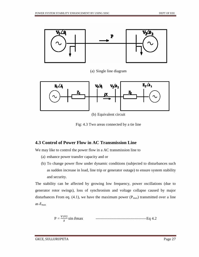
interconnected by a tie line as shown in Fig. 4.3(a). In this case, the power flow in the tie
line (P) in steady state is determined by the mismatch between the generation and load in
the individual areas. Under dynamic conditions, this power flow is determined from the
equivalent circuit shown in Fig. 4.3(b). If the capacity of the tie is small compared to the

POWER SYSTEM STABILITY ENHANCEMENT BY USING SSSC DEPT OF EEE
GKCE, SULLURUPETA Page 26
size (generation) of the two areas, the angles δ1 and δ2 are not affected much by the tie
line power flow. Thus, power flow in AC tie is generally uncontrolled and it becomes
essential to trip the tie during a disturbance, either to protect the tie line or preserve
system security. In comparison with an AC transmission line, the power flow in a HVDC
line is controlled and regulated. However, HVDC converter stations are expensive and
HVDC option is used primarily for
(a) Long distance bulk power transmission
(b) Interconnection of asynchronous systems and
(c) Underwater (submarine) transmission.
The application of HVDC transmission (using thyristor converters) is also constrained by
the problem of commutation failures affecting operation of multiterminal or multi-feed
HVDC systems. This implies that HVDC links are primarily used for point-to-point
transmission of power and asynchronous interconnection (using Back to Back (BTB)
links).
Fig 4.2: Two generating stations supplying a load
POWER SYSTEM STABILITY ENHANCEMENT BY USING SSSC DEPT OF EEE
GKCE, SULLURUPETA Page 27
(a) Single line diagram
(b) Equivalent circuit
Fig: 4.3 Two areas connected by a tie line
4.3 Control of Power Flow in AC Transmission Line
We may like to control the power flow in a AC transmission line to
(a) enhance power transfer capacity and or
(b) To change power flow under dynamic conditions (subjected to disturbances such
as sudden increase in load, line trip or generator outage) to ensure system stability
and security.
The stability can be affected by growing low frequency, power oscillations (due to
generator rotor swings), loss of synchronism and voltage collapse caused by major
disturbances From eq. (4.1), we have the maximum power (Pmax) transmitted over a line
as max
P =
---------------------------------------Eq 4.2
POWER SYSTEM STABILITY ENHANCEMENT BY USING SSSC DEPT OF EEE
GKCE, SULLURUPETA Page 28
Where δmax (30ο - 40
ο) is selected depending on the stability margins and the stiffness of
the terminal buses to which the line is connected. For line lengths exceeding a limit, Pmax
is less than the thermal limit on the power transfer determined by the current carrying
capacity of the conductors (Note this is also a function of the ambient temperature). As
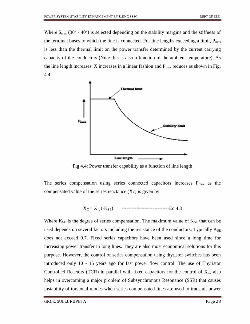
the line length increases, X increases in a linear fashion and Pmax reduces as shown in Fig.
4.4.
Fig 4.4: Power transfer capability as a function of line length
The series compensation using series connected capacitors increases Pmax as the
compensated value of the series reactance (Xc) is given by
XC = X (1-KSE) -----------------------------Eq 4.3
Where KSE is the degree of series compensation. The maximum value of KSE that can be
used depends on several factors including the resistance of the conductors. Typically KSE
does not exceed 0.7. Fixed series capacitors have been used since a long time for
increasing power transfer in long lines. They are also most economical solutions for this
purpose. However, the control of series compensation using thyristor switches has been
introduced only 10 - 15 years ago for fast power flow control. The use of Thyristor
Controlled Reactors (TCR) in parallel with fixed capacitors for the control of XC, also
helps in overcoming a major problem of Subsynchronous Resonance (SSR) that causes
instability of torsional modes when series compensated lines are used to transmit power

POWER SYSTEM STABILITY ENHANCEMENT BY USING SSSC DEPT OF EEE
GKCE, SULLURUPETA Page 29
from turbo generators in steam power stations. In tie lines of short lengths, the power
flow can be controlled by introducing Phase Shifting Transformer (PST) which has a
complex turn’s ratio with magnitude of unity. The power flow in a lossless transmission
line with an ideal PST (see Fig. 4.5) is given by
P =
--------------------------------------Eq 4.4
Where θ = θ1- θ2
Fig 4.5: A lossless line with an ideal PST
Again, manually controlled PST is not fast enough under dynamic conditions. Thyristor
switches can ensure fast control over discrete (or continuous) values of A, depending on
the configuration of PST used. Pmax can also be increased by controlling (regulating) the
receiving end voltage of the AC line. When a generator supplies a unity power factor load
(see Fig. 4.1(b)), the maximum power occurs when the load resistance is equal to the line
reactance. It is to be noted that V2 varies with the load and can be expressed as
V2 = V1 ------------------------- 4.5
Substituting (4.5) in (4.1) gives:
P = V12 / 2X ------------------------4.6
By providing dynamic reactive power support at bus (2) as shown in Fig. (4.6), it is
possible to regulate the bus voltage magnitude. The reactive power (QC) that has to be
injected is given by

POWER SYSTEM STABILITY ENHANCEMENT BY USING SSSC DEPT OF EEE
GKCE, SULLURUPETA Page 30
Fig 4.6: Transmission line compensated by controllable reactive power source at
receiving end
QC = V22 – V1V2 / X --------------------- 4.7
Comparing eq. (4.6) with (4.1), it can be seen that the maximum power transfer can be
doubled just by providing dynamic reactive power support at the receiving end of the
transmission line. This is in addition to the voltage support at the sending end. It is to be
noted that while steady state voltage support can be provided by mechanically switched
capacitors, the dynamic voltage support requires synchronous condenser or a power
electronic controller such as Static Var Compensator (svc) or static synchronous
compensator (STATCOM).
Voltage Source Converter Based Controllers - An Introduction
This section is aimed at giving a brief introduction to the VSC based controller.
The schematic diagram of a STATCOM is shown in Fig. 4.7 while that of a SSSC is
shown in Fig.4.8. The diagram of a UPFC is shown in Fig. 4.9.
Fig: 4.7 Shunt connected STATCOM

POWER SYSTEM STABILITY ENHANCEMENT BY USING SSSC DEPT OF EEE
GKCE, SULLURUPETA Page 31
Fig 4.8: Series connected SSSC
Fig 4.9: Unified power flow controller
A six pulse Voltage Source Converter (VSC) is shown in Fig. 4.10. By suitable
control, the phase and the magnitude of the AC voltage injected by the VSC can be
controlled. The Phase Lock Loop (PLL) ensures that the sinusoidal component of the
injected voltage is synchronized (matching in frequency and required phase angle) with
the voltage of the AC bus to which VSC is connected through an inductor. Often, the
leakage impedance of the interconnecting transformer serves as the inductive impedance
that has to separate the sinusoidal bus voltage and the voltage injected by the VSC (which
contains harmonics). The injection of harmonic voltages can be minimized by multipulse
(12, 24 or 48), and/or multilevel convertors. At low power levels, it is feasible to provide
pulse width modulation (PWM) to control the magnitude of the fundamental component
of the injected voltage. The high voltage IGBT devices can be switched up to 2 kHz and
high frequency of sinusoidal modulation enables the use of simple L-C (low pass) filters
to reduce harmonic components.

POWER SYSTEM STABILITY ENHANCEMENT BY USING SSSC DEPT OF EEE
GKCE, SULLURUPETA Page 32
Fig 4.10: A three phase six pulse VSC
The operation of a VSC can be explained with reference to a single phase (half-wave)
convertor shown in Fig. 4.11. This can represent one leg of the 3 phase VSC.
Fig 4.11:- A single phase half wave rectifier
TA+ and TA- are controllable switches which can be switched on or off at controllable
instants in a cycle. The diodes ensure that the current can flow in both directions in the
DC capacitor. The switches TA+ and TA- work in complementary fashion - only one of
them is on while the other is off. If the switch is turned on only once during a cycle, this
is called as the square-wave switching scheme with each switch conducting for 180˚in a
cycle. The peak value of the fundamental component (VAN1) is given by
VAN1=
----------------------------4.8
The waveform contains odd harmonics with the magnitudes
VANh=
---------------4.9

POWER SYSTEM STABILITY ENHANCEMENT BY USING SSSC DEPT OF EEE
GKCE, SULLURUPETA Page 33
It is to be noted that in the square wave switching scheme, only the phase angle of the
voltage injected by the VSC can be controlled (and not the magnitude) . In a three phase
converter with 3 legs the triplen harmonics will disappear such that the non-zero
harmonic order (h) is given by
h = 6n ± 1, n = 1, 2…. --------------------------------4.10
Increasing the pulse number from six to twelve has the effect of eliminating the
harmonics corresponding to odd values of n. The introduction of PWM has the effect of
controlling the magnitude of the fundamental component of the injected voltage by the
VSC. For this case, the waveform of the voltage VAN is shown in Fig. 4.12. Using
sinusoidal modulation (with triangular carrier wave), the peak value of the injected
sinusoidal voltage can be expressed as
VAN1= m
--------------------------------------4.11
Where m is called the modulation index. The maximum modulation index can be
achieved with space vector modulation and is given by
M max =
----------------------------------------------4.12
It is to be noted that the modulation index (m) and the phase angle (α) are controlled to
regulate the injected current by the shunt connected VSC. Neglecting losses, a
STATCOM can only inject reactive current in Steady state. The reactive current
reference can be controlled to regulate the bus voltage. In a similar fashion the reactive
voltage injected by a lossless SSSC can be controlled to regulate the power flow in a line
within limits.

POWER SYSTEM STABILITY ENHANCEMENT BY USING SSSC DEPT OF EEE
GKCE, SULLURUPETA Page 34
Fig 4.12: Waveform of VAN and the fundamental component
. The combination of a STATCOM and a SSSC, in which the STATCOM feeds (or
absorbs) power on the DC side to SSSC, can be used to regulate both active and reactive
power flow in a line (subject to the constraints imposed by the ratings of the converters in
addition to the limits on bus voltages).
Introduction-SSSC:-
The Static Synchronous Series Compensator (SSSC) is a series connected FACTS
controller based on VSC and can be viewed as an advanced type of controlled series
compensation, just as a STATCOM is an advanced SVC. A SSSC has several advantages
over a TCSC such as
(a) Elimination of bulky passive components like capacitors and reactors,
(b) Improved technical characteristics
(c) Symmetric capability in both inductive and capacitive operating modes
(d) Possibility of connecting an energy source on the DC side to exchange real power
with the AC network.

POWER SYSTEM STABILITY ENHANCEMENT BY USING SSSC DEPT OF EEE
GKCE, SULLURUPETA Page 35
However, a SSSC is yet to be installed in practice except as a part of UPFC or
Convertible Static Compensator (CSC). An example of the former is a 160 MVAR series
connected converter as part of the Unified Power Flow Controller installed at Inez station
of American Electric Power (AEP). An example of the latter are the two, 100 MVA
series connected converters at Marcy 345 KV substation in Central New York belonging
to NYPA. In both cases, 24 pulse three-level converters are used. This topology reduces
the injected harmonic voltages considerably and there is no need for harmonic filters.
BASIC OPERATING MODES FOR THE SSSC:- There are several possible control
strategies:
Constant Voltage Injection Mode: - In this mode the SSSC generates a three phase
voltage with Respect to a reference input. The direct voltage injection mode is used to
provide purely reactive series compensation where the injected voltage is always kept in
quadrature with the line current.
Constant Impedance Emulation Mode: - This control mode provides a opportunity for
operator to control the total line impedance, which can be specified by the reference
input. The series injected voltage will create, via the series transformer, virtual
impedance seen by the transmission line.
Constant Power Control Mode:- Under this mode, the injected voltages can he variable
in Magnitude and phase angle in order to control the power flow to be constant. This
control Mode can also be used for improving system transient stability.
Basic SSSC function:-
Electric power flow through an alternating current transmission line is a
function of the line impedance, the magnitudes of the sending-end and receiving-end
voltages, and the phase angle between these voltages. The power flow can be decreased
by inserting an additional inductive reactance in series with the transmission line, thereby
increasing the effective reactance of the transmission line between its two ends. Also, the
power flow can be increased by inserting an additional capacitive reactance in series with
the transmission line, thereby decreasing the effective reactance of the transmission line
between its two ends. Traditionally, in order to control the power flow of the transmission

POWER SYSTEM STABILITY ENHANCEMENT BY USING SSSC DEPT OF EEE
GKCE, SULLURUPETA Page 36
line, the effective line reactance is controlled by using fixed or thyristor-controlled series
capacitors or inductors.
Recently, a new power flow controller entitled Transmission Line Dynamic
Impedance Compensation System which uses solid state switching converters has been
proposed. With the use of the impedance compensation controller, a Static Synchronous
Series Compensator (SSSC), which is a solid-state voltage source inverter, injects an
almost sinusoidal voltage, of variable magnitude, in series with a transmission line. This
injected voltage is almost in quadrature with the line current. A small part of the injected
voltage which is in phase with the line current provides the losses in the inverter. Most of
the injected voltage which is in quadrature with the line current emulates an inductive or
a capacitive reactance in series with the transmission line. This emulated variable
reactance, inserted by the injected voltage source, influences the electric power flow in
the transmission line.
An impedance compensation controller can compensate for the transmission line
resistance if an SSSC is operated with an energy storage system. An impedance
compensation controller, when used with an SSSC and no energy storage system, is
essentially a reactance compensation controller. The reactance compensation controller is
used to operate the inverter in such a way that the injected alternating voltage in series
with the transmission line is proportional to the line current with the emulated reactance
being the constant of proportionality. When an SSSC injects an alternating voltage
leading the line current, it emulates an inductive reactance in series with the transmission
line causing the power flow as well as the line current to decrease as the level of
compensation increases and the SSSC is considered to be operating in an inductive mode.
When an SSSC injects an alternating voltage lagging the line current, it emulates a
capacitive reactance in series with the transmission line causing the power flow as well as
the line current to increase as the level of compensation increases and the SSSC is
considered to be operating in a capacitive mode. FACTS devices consist of a solid-state
voltage source inverter with several Gate Turn off (GTO) thyristor switch-based valves
and a DC link capacitor, a magnetic circuit, and a controller. The number of valves and

POWER SYSTEM STABILITY ENHANCEMENT BY USING SSSC DEPT OF EEE
GKCE, SULLURUPETA Page 37
the various configurations of the magnetic circuit depend on the desired quality of AC
waveforms generated by the FACTS devices.
Theory:-
Fig 4.13 shows a single line diagram of a simple transmission line with an inductive
reactance, X,, connecting a sending-end voltage source, Vs , and a receiving-end voltage
source, Vr , respectively.
Fig 4.13: An elementary transmission power system
The real and reactive power (P and Q) flow at the receiving-end voltage source is given
by the expressions:-
P =
------------------------------------------------4.13 (a)
And
Q =
---------------------------4.14(b)
Where Vs and Vr are the magnitudes and δs and δr are the phase angles of the voltage
sources Vs and Vr respectively. For simplicity, the voltage magnitudes are chosen such
that Vs = Vr =V and the difference between the phase angles is δ = δs - δr. An SSSC,
limited by its voltage and current ratings, is capable of emulating a compensating
reactance, Xq, (both inductive and capacitive) in series with the transmission line
inductive reactance, X, Therefore, the expressions for power flow given in equation (1)
become XL(1-Xq / XL)

POWER SYSTEM STABILITY ENHANCEMENT BY USING SSSC DEPT OF EEE
GKCE, SULLURUPETA Page 38
P q =
-----------------------------------------4.15
And
Qq =
--------------------------------------4.16
Where Xeff is the effective reactance of the transmission line between its two ends,
including the emulated variable reactance inserted by the injected voltage source of the
SSSC. The compensating reactance, Xq, is defined to be negative when the SSSC is
operated in an inductive mode and positive when the SSSC is operated in a capacitive
mode.
4.4 STATIC SYNCHRONOUS SERIES COMPENSATOR (SSSC)
WORKING:-
The voltage–sourced converter-based series compensator, called static
synchronous series compensator (SSSC) ,was proposed by Gyugyi in 1989 within the
concept of using converter-based technology uniformly for shunt and series
compensation, as well as for transmission angle control. The basic operation principle of
the SSSC can be explained with reference to the fig 4.13 together with the related voltage
phasor diagram. The phasor diagram clearly shows that at a given line current the voltage
across the series capacitor forces the opposite polarity voltage across the series line
reactance to increases by the magnitude of the capacitor voltage. thus, the series
capacitive compensation works by increasing the voltage across the impedance of the
given physical line, which in turn increases the corresponding line current and the
transmitted power, while it may be convenient to consider series capacitive compensation
as a means of reducing the line impedance, in reality, as explained previously, it is really
a means of increasing the voltage across the given impedance of the physical line. it
follows therefore that the same steady-state power transmission can be established if the

POWER SYSTEM STABILITY ENHANCEMENT BY USING SSSC DEPT OF EEE
GKCE, SULLURUPETA Page 39
series compensation is provided by a synchronous ac voltage source, as shown in fig
4.14, whose output precisely matches the voltage of the series capacitor ,i.e.,
Vq = Vc = -JXCI = -JKXI ---------------------------------- (4.17)
Where, as before, Vc is the injected compensating voltage phasor, I is the line current, Xc
is the reactance of the series capacitor. X is the line reactance, K=Xc/X is the degree of
series compensating, and J=√-1. Thus , by making the output voltage of the synchronous
voltage source a function of the line current, as specified by (4.17), the same
compensation as provided by the series capacitor is accomplished . However, in contrast
to the real series capacitor, the SVS is able to maintain a constant compensating voltage
in the presence of variable line current, or control the amplitude of the injected
compensating voltage independent of the amplitude of the line current.
For normal capacitive compensation, the output voltage lags the line current by 90
degrees. For SVS, the output voltage can be reversed by simple control action to
Basic two-machine system with a series capacitor compensated line and associated
phasor diagram

POWER SYSTEM STABILITY ENHANCEMENT BY USING SSSC DEPT OF EEE
GKCE, SULLURUPETA Page 40
Figure 4.14: Basic two-machine system as in figure 6.30 but with synchronous voltage
source replacing the series capacitor
Make it lead or lag the line current by 90 degrees. In the case, the injected voltage
decreases the voltage across the inductive line impedance and thus the series
compensation has the same effect as if the reactive line impedance was increased
With above observations, a generalized expression for the injected voltage,
Vq, can simply be written :
Vq= ± JVq(ζ)
--------------------------(4.18)
Where Vq (ζ) is the magnitude of the injected compensating voltage (0 ≤ Vq (ζ) ≤ Vqmax)
and ζ is a chosen control parameter. the series reactive compensation scheme, using a
switching power converter (voltage-sourced converter) as a synchronous voltage source
to produce a controllable voltage in quadrature with the liner current as defined by(4.18)
is , per IEEE and CIGRE definition, termed the static synchronous series compensator
(SSSC).
Transmitted power versus transmission angle characteristic:-
The SSSC injects the compensating voltage in series with the line irrespective of the line
current. The transmitted power Pq verses the transmission angles δ relationship therefore
becomes a parametric function of the injected voltage, Vq, and it can be expressed for a
two machine system as follows:

POWER SYSTEM STABILITY ENHANCEMENT BY USING SSSC DEPT OF EEE
GKCE, SULLURUPETA Page 41
P=
SIN δ +
Vq COS δ/2 ------------------ (4.19)
The normalized power P verses angle δ plots as a parametric function of Vq are shown in
fig 6.32 for Vq =0, ± 0.353, and ± 0.707. for comparison, the normalized power P versus
angle δ plots of a series capacitor compensated two machine system are shown in fig 4.16
as a parametric function of the degree of series compunction K. For this comparison, K is
chosen to give the same maximum power as the SSSC with corresponding Vq. that is, at
δ=90 degree, k=1/5 when Vq=0.353 and k=1/3 when Vq=0.707.
Comparison of the corresponding plots in figures 4.15 and 4.16 clearly shows that the
series capacitor increase the transmitted power by a fixed percentage of that transmitted
by the uncompensated line at a given δ and, by contrast, the SSSC can increases it by a
fixed fraction of the maximum power transmittable by the uncompensated line,
independent of δ in the important operating range of 0≤δ≤Π/2.
Fig 4.15 Transmitted power vs. transmission angle provided by the SSSC as a parametric
function of the series compensation voltage.

POWER SYSTEM STABILITY ENHANCEMENT BY USING SSSC DEPT OF EEE
GKCE, SULLURUPETA Page 42
Figure 4.16 transmitted power vs. transmission angle attainable with series capacitive
compensation as a parametric function of the degree of series compensation
Figure 4.17 oscillograms from TNA simulation showing the capability of the SSSC to
control as well as reverse real power flow

POWER SYSTEM STABILITY ENHANCEMENT BY USING SSSC DEPT OF EEE
GKCE, SULLURUPETA Page 43
For applications requiring (steady-state or dynamic) power flow control, the basic
P versus δ characteristic shown in figure 4.15 indicates that the SSSC, similarly to the
statcom, inherently has twice as wide controlled compensation range as the VA rating of
the converter. This means that the SSSC can decrease, as well as increases the power
flow to the same degree, simply by reversing the polarity of the injected ac voltage. The
reversed (180 degree phase shift) voltage adds directly to the reactive voltage drop of the
line as if the reactive line impedance was increased. further more, if this (reverse polarity)
injected voltage is made larger than the voltage impressed across the uncompensated line
by the sending and receiving-end systems, that is, if Vq >|Vs-Vr|, then the power flow will
reverse with the line current I = (Vq >|Vs-Vr|)/X , as indicated in figure 4.15.
The feasibility of reversing power flow by reactive compensation is demonstrated
in figure 4.16 by the results obtained from the TNA simulation of a simple two- machine
system controlled by a precisely detailed SSSC hardware model. the plots in the figure
shows, at δ=10 degree , the line current I together with the receiving- end (l-n) voltage Vr
= V2 for phase A, the transmitted power P together with the reactive power Q supplied by
the receiving end, the same line current I together with the voltage Vq injected by the
SSSC in phase A, and the reactive power the SSSC exchanged with the ac system for no
compensation (Vq=0), purely reactive compensation for positive power flow (Vq = IX -
|Vs-Vr|), and purely reactive compensation for negative flow (Vq = IX + |Vs-Vr|). Apart
from the stable operation of the system with both positive and negative power flows, it
can also be observed that the SSSC has, as expected (sub cycle) response time and that
the transition from positive to negative power flow through zero voltage injection is
perfectly smooth and continuous.
Apart from the bi-directional compensation capability, the basic operation
characteristic of the SSSC also suggests a significant difference between the behaviors of
SSSC and the series capacitor under the condition of variable line reactance that the
reader should note. The gist of this difference is that the SSSC could not be tuned with
any finite line inductive to have a classical series resonance (at which the capacitive and
inductive would be equal) at the fundamental frequency, because the voltage across the
line reactance would, in all practical cases, be greater than, and this compensating voltage

POWER SYSTEM STABILITY ENHANCEMENT BY USING SSSC DEPT OF EEE
GKCE, SULLURUPETA Page 44
is set by the control and it is independent of network impedance (and, consequently, line
current) changes. That is, the voltage Vx across an ideal line of reactance X (R=0) at a
fixed δ is the function of only the compensating voltage Vq injected by the SSSC, that is
VX=IX=Vq + 2V SIN δ/2 ------------------------------------------ (4.20)
Where again V is the ac system (l-n) voltage and δ is the transmission angle. As (4.20)
shows, Vx can be equal to Vq only if δ=0, in which case the transmission would be
controlled entirely by the SSSC as if it were a generator and the line current would be
restricted to the operating range of 0≤ I ≤
. (It should be noted that the SSSC would
require an external dc power supply for the replenishment of its internal losses to be able
to establish power transmission at zero transmission angle.)
Immunity to sub synchronous resonance:-
The desired function of the series capacitor is to provide a compensating
voltage opposite to that which develops across the reactive line impedance at the
fundamental system frequency to increase the transmitted power. However, the
impedance of the series capacitor is a function of frequency and thus it can cause
resonance at various subsynchronous frequencies with other reactive impedance present
in the network. As discussed in previous sections, in recent years there has been
considerable progress made in modifying the inherent frequency band by a parallel
connected thyristor-controlled reactor, making it immune to subsynchronous resonance
with the use of electronic control.
In contrast to a series capacitor and an impedance type series compensator, the
voltage-sourced converter-based static synchronous series compensator is essentially an
AC voltage source which, with a constant DC voltage and fixed control inputs, would
operate only at the selected (fundamental) output frequency, and its output impedance at
other frequencies would theoretically be zero. In practice, the SSSC does have relatively
small inductive output impedance provided by the leakage inductance of the series
insertion transformer. The voltage drop across this impedance is automatically

POWER SYSTEM STABILITY ENHANCEMENT BY USING SSSC DEPT OF EEE
GKCE, SULLURUPETA Page 45
compensated at the fundamental frequency when the SSSC provided capacitive line
compensation.
A sufficient condition for the SSSC to remain neutral to sub synchronous
oscillations, independently of system conditions, is to keep its instantaneous output
voltage vector (representing the output voltage of the converter) in quadrature with the
instantaneous line current vector.
SSSC RATING:-
The SSSC can provide capacitive or inductive compensating voltage independent of
the line current independent of the line current upto its specified current rating. The
voltage ampere rating of the of the SSSC is simply the product of the maximum line
current and the maximum series compensating voltage.
VA = ImaxVqmax
4.5 APPLICATIONS OF SSSC:-
A SSSC is an advanced version of controlled series compensation that is based on
VSC and the use of GTOs instead of thyristors. There are many technical advantages of a
SSSC over a TCSC. However, the application of a SSSC would depend on the techno-
economic evaluation and proven reliability based on operating experience. A major
drawback with SSSC is the need
for a coupling transformer (and an intermediate transformer if multiples converters are
used). In contrast, TCSCs don't require any magnetic devices or coupling transformers.
However, the harmonics are better controlled with a SSSC. A SSSC requires protection
against over currents. A high speed electronic Thyristor Bypass Switch (TBS) is installed
in parallel with the converter terminals. When an over current is detected, it operates
quite fast. In case the system fault is not cleared by primary protection, then, the TBS is
protected by a parallel connected low voltage breaker (LVB) which by- passes the TBS in
about 6 cycles. If LVB fails to close when required, then its breaker failure protection
closes the high side breaker (HSB) that by passes the SSSC. After the fault is cleared, the
SSSC is reinserted into the line by opening the LVB. The improvements in the power
(semiconductor) device characteristics and the reduction in the costs would spur the
applications of SSSC in place of TCSC.

POWER SYSTEM STABILITY ENHANCEMENT BY USING SSSC DEPT OF EEE
GKCE, SULLURUPETA Page 46
CHAPTER 5
INTRODUCTION TO MATLAB

POWER SYSTEM STABILITY ENHANCEMENT BY USING SSSC DEPT OF EEE
GKCE, SULLURUPETA Page 47
5. INTRODUCTION TO MATLAB
5.1 MATLAB
MATLAB is a software package for computation in engineering, science, and applied
mathematics. It offers a powerful programming language, excellent graphics, and a wide
range of expert knowledge. MATLAB is published by and a trademark of The Math
Works, Inc.The focus in MATLAB is on computation, not mathematics: Symbolic
expressions and manipulations are not possible (except through the optional Symbolic
Toolbox, a clever interface to maple). All results are not only numerical but inexact,
thanks to the rounding errors inherent in computer arithmetic. The limitation to numerical
computation can be seen as a drawback, but it’s a source of strength too: MATLAB is
much preferred to Maple, Mathematical, and the like when it comes to numeric’s.
On the other hand, compared to other numerically oriented languages like C++
and FORTRAN, MATLAB is much easier to use and comes with a huge standard
library.1 the unfavorable comparison here is a gap in execution speed. This gap is not
always as dramatic as popular lore has it, and it can often be narrowed or closed with
good MATLAB programming (see section 6). Moreover, one can link other codes into
MATLAB, or vice versa, and MATLAB now optionally supports parallel computing.
Still, MATLAB is usually not the tool of choice for maximum-performance Computing.
The MATLAB niche is numerical computation on workstations for non-experts
in computation. This is a huge niche—one way to tell is to look at the number of
MATLAB-related books on mathworks.com. Even for supercomputer users, MATLAB
can be a valuable environment in which to explore and fine-tune algorithms before more
laborious coding in another language. Most successful computing languages and
environments acquire a distinctive character or culture. In MATLAB, that culture
contains several elements: an experimental and graphical bias, resulting from the
interactive environment and compression of the write-compile-link-execute analyze
cycle; an emphasis on syntax that is compact and friendly to the interactive mode, rather

POWER SYSTEM STABILITY ENHANCEMENT BY USING SSSC DEPT OF EEE
GKCE, SULLURUPETA Page 48
than tightly constrained and verbose; a kitchen-sink mentality for providing functionality;
and a high degree of openness and transparency (though not to the extent of being open
source software).The component that is the heart of MATLAB is called the Command
Window, located on the 1Here and elsewhere I am thinking of the “old FORTRAN,”
FORTRAN 77. This is not a commentary on the usefulness of FORTRAN 90 but on my
ignorance of it.
5.2 SIMULINK:-
Simulink (Simulation and Link) is an extension of MATLAB by Math works Inc. It
works with MATLAB to offer modeling, simulating, and analyzing of dynamical systems
under a graphical user interface (GUI) environment. The construction of a model is
simplified with click-and-drag mouse operations. Simulink includes a comprehensive
block library of toolboxes for both linear and nonlinear analyses. Models are hierarchical,
which allow using both top-down and bottom-up approaches. As Simulink is an integral
part of MATLAB, it is easy to switch back and forth during the analysis process and thus,
the user may take full advantage of features offered in both environments. This tutorial
presents the basic features of Simulink and is focused on control systems as it has been
written for students in my control system
SimPowe Systems:-
SimPowerSystems is a modern design tool that allows scientists and engineers to
rapidly and easily build models that simulate power systems. SimPowerSystems uses the
Simulink environment, allowing you to build a model using simple click and drag
procedures. Not only can you draw the circuit topology rapidly, but your analysis of the
circuit can include its interactions with mechanical, thermal, control, and other
disciplines. This is possible because all the electrical parts of the simulation interact with
the extensive Simulink modeling library. Since Simulink uses MATLAB® as its
computational engine, designers can also use MATLAB toolboxes and Simulink block
sets. SimPowerSystems and Sim Mechanics share a special Physical Modeling block and
connection line interface.
POWER SYSTEM STABILITY ENHANCEMENT BY USING SSSC DEPT OF EEE
GKCE, SULLURUPETA Page 49
SimPowerSystems Libraries:-
You can rapidly put SimPowerSystems to work. The libraries contain models of
typical power equipment such as transformers, lines, machines, and power electronics.
These models are proven ones coming from textbooks, and their validity is based on the
experience of the Power Systems Testing and Simulation Laboratory of Hydro-Québec, a
large North American utility located in Canada, and also on the experience of Ecolab de
Technologies Superiors and University Laval.
The capabilities of SimPowerSystems for modeling a typical electrical system are
illustrated in demonstration files. And for users who want to refresh their knowledge of
power system theory, there are also self-learning case studies. The SimPowerSystems
main library, power lib, organizes its blocks into libraries according to their behavior.
The power lib library window displays the block library icons and names. Double-click a
library icon to open the library and access the blocks. The main SimPowerSystems power
lib library window also contains the Powerful block that opens a graphical user interface
for the steady-state analysis of electrical circuits.

POWER SYSTEM STABILITY ENHANCEMENT BY USING SSSC DEPT OF EEE
GKCE, SULLURUPETA Page 50
CHAPTER 6
TWO MACHINE POWER SYSTEM MODELLING

POWER SYSTEM STABILITY ENHANCEMENT BY USING SSSC DEPT OF EEE
GKCE, SULLURUPETA Page 51
6. TWO MACHINE POWER SYSTEM MODELLING
6.1 INTRODUCTION:-
The dynamic performance of SSSC is presented by real time voltage and current
waveforms. Using MATLAB software the system shown in Fig 6.1 has been obtained. In
the simulation one SSSC has been utilized to control the power flow in the 500 KV
transmission systems. This system which has been made in ring mode consisting of 4
buses (B1 to B4) connected to each other through three phase transmission lines L1, L2-
1, L2-2 and L3 with the length of 280, 150, 150 and 5 km respectively. System has been
supplied by two power plants on either side.
Fig 6.1 Two machine power system without SSSC
First, power system with two machines and four buses has been simulated in
MATLAB environment, and then powers and voltages in all buses have been obtained.
Using obtained results bus-2 has been selected as a candidate bus to which the SSSC be

POWER SYSTEM STABILITY ENHANCEMENT BY USING SSSC DEPT OF EEE
GKCE, SULLURUPETA Page 52
installed. Therefore, the simulation results have been focused on bus-2. The simulation
circuits with and without SSSC has been shown in fig 6.1 and fig 6.2 respectively.
By using SSSC in two machine power system across bus -2 the oscillations
magnitude during transient period is decreased well, thus improving the transient stability.
We already know that by using SSSC we can control active and reactive power i.e. we can
either inject or absorb by making output voltage of the SSSC in quadrature with line
current. In the present case the desired values of active and reactive powers are 4 p.u and -
6 p.u. so by making use of correct control strategy of the SSSC we can get the desired
values. The converter circuit of the SSSC is shown in fig 6.3.
Fig 6.2 Two machine power system with SSSC

POWER SYSTEM STABILITY ENHANCEMENT BY USING SSSC DEPT OF EEE
GKCE, SULLURUPETA Page 53
6.2 CONTROL STRATEGY OF SSSC:-
SSSC is nothing but a voltage source converter such that required output
voltage (A.C) is obtained from a DC source. The gating signals for the igbt’s are
obtained from the pwm generator such that the input to it is given from control circuit
shown in the fig 6.4. The voltage and current from the concerned bus 2 are sampled and
and taken in control circuit in order to get the out1 ,out2 and out 3 which are given to
pwm generator. For reason of economics and performance, voltage-sourced converters
are often performed over current-sourced converters for FACTS applications , since the
direct current in a voltage-sourced converter flows in either direction, the converter
valves have to be bidirectional. On the dc side, voltage is unipolar and is supported by a
capacitor (it is not used in simulation circuit).This capacitor is large enough to at least
handle a sustained charge/discharge current that accompanies the switching sequence of
the converter values and shifts in phase angle of the switching without significant change
in the dc voltage.
In the dc side that the dc current flows in either direction and that it can
exchange dc power with the constant dc system in either direction. Shown on the ac side
is the generator ac voltage connected to the ac system via an inductor. Being an ac
voltage source with low internal impedance, a series inductive with the ac system
(usually through a series inductor and/a transformer) is essential to ensure that dc
capacitor is not short circuited and discharged rapidly into a capacitive loads such as a
transmission line. Also an ac filter is necessary following the series inductive interface to
limit the consequent current harmonics entering the system side.

POWER SYSTEM STABILITY ENHANCEMENT BY USING SSSC DEPT OF EEE
GKCE, SULLURUPETA Page 54
Fig 6.3 Converter circuit of SSSC
The voltage sampled from bus 2 is given to the discrete 3 – phase PLL in
order to obtain the concerned phase angle. The voltage, current which are in abc reference
are transformed to dq reference by using abc to dq transformation and Pact and Qact are
obtained. Actual and reference values of active and reactive powers are compared and the
generated error is minimized by using the parameters in PI controller. The output
parameter obtained from the PI controller is again transformed to abc reference by using
dq to abc transformation. The generated output is compared with the current samples
taken from the output of SSSC such that out1 ,out2 and out3 are generated which are
given to pwm generator. The output voltage and current waveforms with and without
SSSC are shown in fig 6.5

POWER SYSTEM STABILITY ENHANCEMENT BY USING SSSC DEPT OF EEE
GKCE, SULLURUPETA Page 55
Fig 6.4 control circuit of SSSC
Basically a voltage –sourced converter generates ac voltage for a dc voltage. It
is for historical reasons, offten referred to as an inverter, Even though it has the capability
to transfer the power in either direction. with a voltage source converter, the magnitude,
the phase angle and the frequency of output can be controlled. The voltage ,current
,active and reactive powers are measured by using following measurement circuit.

POWER SYSTEM STABILITY ENHANCEMENT BY USING SSSC DEPT OF EEE
GKCE, SULLURUPETA Page 56
WITHOUT SSSC
WITH SSSC
Fig 6.5 voltage and current waveforms with and without SSSC

POWER SYSTEM STABILITY ENHANCEMENT BY USING SSSC DEPT OF EEE
GKCE, SULLURUPETA Page 57
The active and reactive powers with and without SSSC is shown in fig 6.6
WITHOUT SSSC
WITH SSSC
Fig 6.6 active and reactive powers with and without SSSC

POWER SYSTEM STABILITY ENHANCEMENT BY USING SSSC DEPT OF EEE
GKCE, SULLURUPETA Page 58
By using SSSC the nature of transient stability is increased and damping time decreased to some
extent thus enhancing the power system stability. Generally just after load is charged or during
switching transient oscillations occurs even we use SSSC but the magnitude of the oscillations is
less with using SSSC. However controlling systems in power plants 1 and 2 such as governor,
PSS and other stabilizing units are used for damping these oscillations.
POWER SYSTEM STABILITY ENHANCEMENT BY USING SSSC DEPT OF EEE
GKCE, SULLURUPETA Page 59
CONCLUSION
It has been found that the SSSC is capable of controlling the flow of power at
a desired point on the transmission line. It is also observed that the SSSC injects a fast
changing voltage in series with the line irrespective of the magnitude and phase of the
line current. Based on obtained simulation results the performance of the SSSC has been
examined in a simple two-machine system simply on the selected bus-2, and applications
of the SSSC will be extended in future to a complex and multimachine system to
investigate the problems related to the various modes of power oscillation in the power
systems.

POWER SYSTEM STABILITY ENHANCEMENT BY USING SSSC DEPT OF EEE
GKCE, SULLURUPETA Page 60
BIBLIOGRAPHY
1. UNDERSTANDING FACTS by NARAIN G HINGORANI and LASZLO GUIGOI.
2. FACTS by KR PADIYAR.
3. Websites referred: - www.ieee.org
www.siemens.com
www.wikipedia.com


