28


Healthcare Facilities
Web Hosting, Internet Data Centers
Commercial Buildings / Industrial Buildings
Telecom Central Offices
Process Manufacturing / Wafer Fabrication Plants /
Distributed Power / Load Management
2
As we become moredependent on the qualityand reliability of electricalpower, interruption or complete loss of power cancreate serious and even crippling financial losses, orimpose dangers to life andsafety.
ASCO Power Technologies(ASCO) provides the solu-tions to handle the transferof critical loads to emer-gency sources reliably andwith state of the art prod-ucts. Using ASCO productscan mean the differencebetween a minor inconven-ience and a major catastro-phe. You’ll find ASCO PowerTransfer Switches whereverthere is a critical load to beprotected.
When flexibility in powerswitching is a must, ASCOoffers a variety of product solutions to meet virtuallyevery application require-ment, including distributedgeneration applications.That’s why the 7000 SERIES
is available in open, delayed,closed and closed soft loadconfigurations. Additionally,switched or overlappingneutral options provide forreliable operation of groundfault protection systems andreduction of voltage tran-sients from unbalanced loadswitching.
ASCO Power TransferSwitches are the first CEMarked, IEC 60947-6-1 com-pliant Transfer Switches inthe world.
ASCO 7000 SERIES
Power Transfer Switches
Critical Loads Demand ASCO
Protecting:
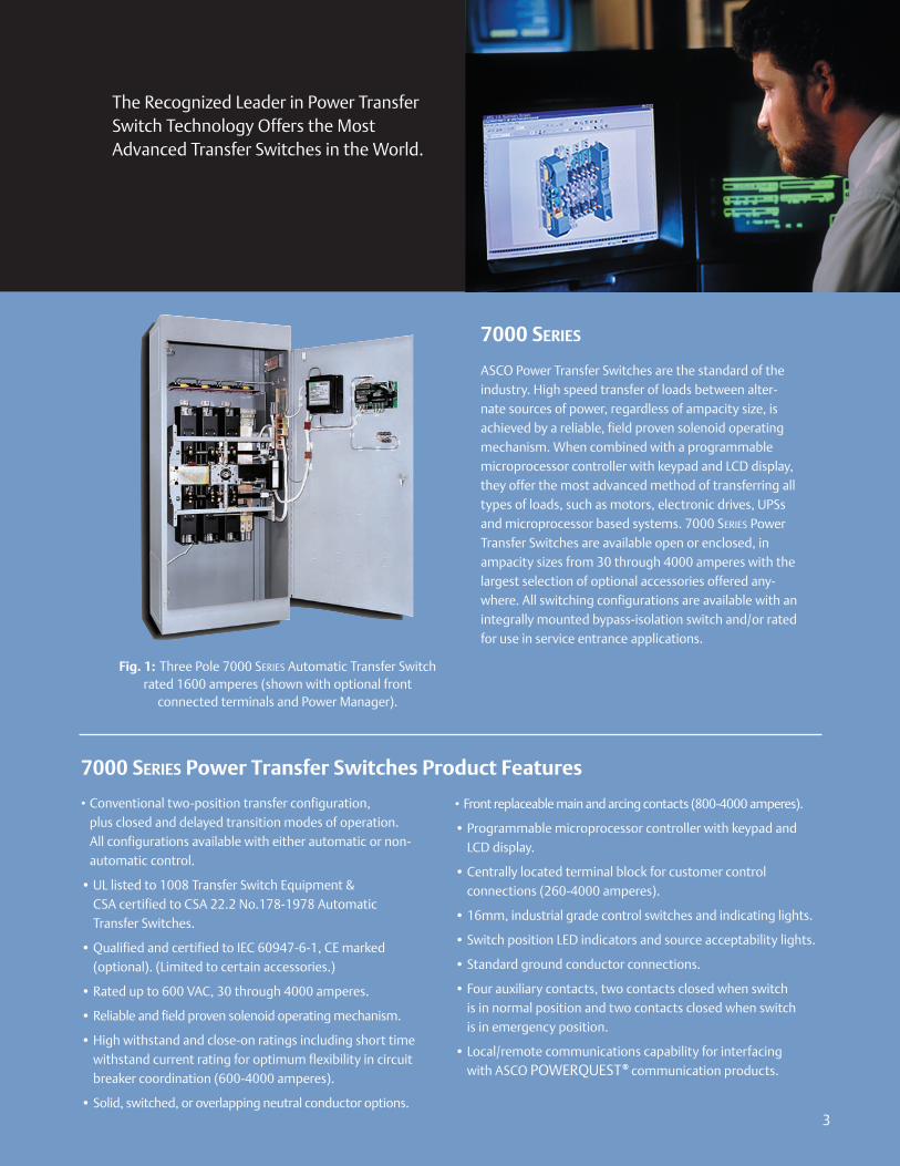
The Recognized Leader in Power TransferSwitch Technology Offers the MostAdvanced Transfer Switches in the World.
• Conventional two-position transfer configuration, plus closed and delayed transition modes of operation. All configurations available with either automatic or non-automatic control.
• UL listed to 1008 Transfer Switch Equipment & CSA certified to CSA 22.2 No.178-1978 AutomaticTransfer Switches.
• Qualified and certified to IEC 60947-6-1, CE marked(optional). (Limited to certain accessories.)
• Rated up to 600 VAC, 30 through 4000 amperes.
• Reliable and field proven solenoid operating mechanism.
• High withstand and close-on ratings including short timewithstand current rating for optimum flexibility in circuitbreaker coordination (600-4000 amperes).
• Solid, switched, or overlapping neutral conductor options.
ASCO Power Transfer Switches are the standard of theindustry. High speed transfer of loads between alter-nate sources of power, regardless of ampacity size, isachieved by a reliable, field proven solenoid operatingmechanism. When combined with a programmablemicroprocessor controller with keypad and LCD display,they offer the most advanced method of transferring alltypes of loads, such as motors, electronic drives, UPSsand microprocessor based systems. 7000 SERIES PowerTransfer Switches are available open or enclosed, inampacity sizes from 30 through 4000 amperes with thelargest selection of optional accessories offered any-where. All switching configurations are available with anintegrally mounted bypass-isolation switch and/or ratedfor use in service entrance applications.
• Front replaceable main and arcing contacts (800-4000 amperes).
• Programmable microprocessor controller with keypad andLCD display.
• Centrally located terminal block for customer control connections (260-4000 amperes).
• 16mm, industrial grade control switches and indicating lights.
• Switch position LED indicators and source acceptability lights.
• Standard ground conductor connections.
• Four auxiliary contacts, two contacts closed when switch is in normal position and two contacts closed when switch is in emergency position.
• Local/remote communications capability for interfacing with ASCO POWERQUEST® communication products.
3
7000 SERIES
7000 SERIES Power Transfer Switches Product Features
Fig. 1: Three Pole 7000 SERIES Automatic Transfer Switchrated 1600 amperes (shown with optional front
connected terminals and Power Manager).
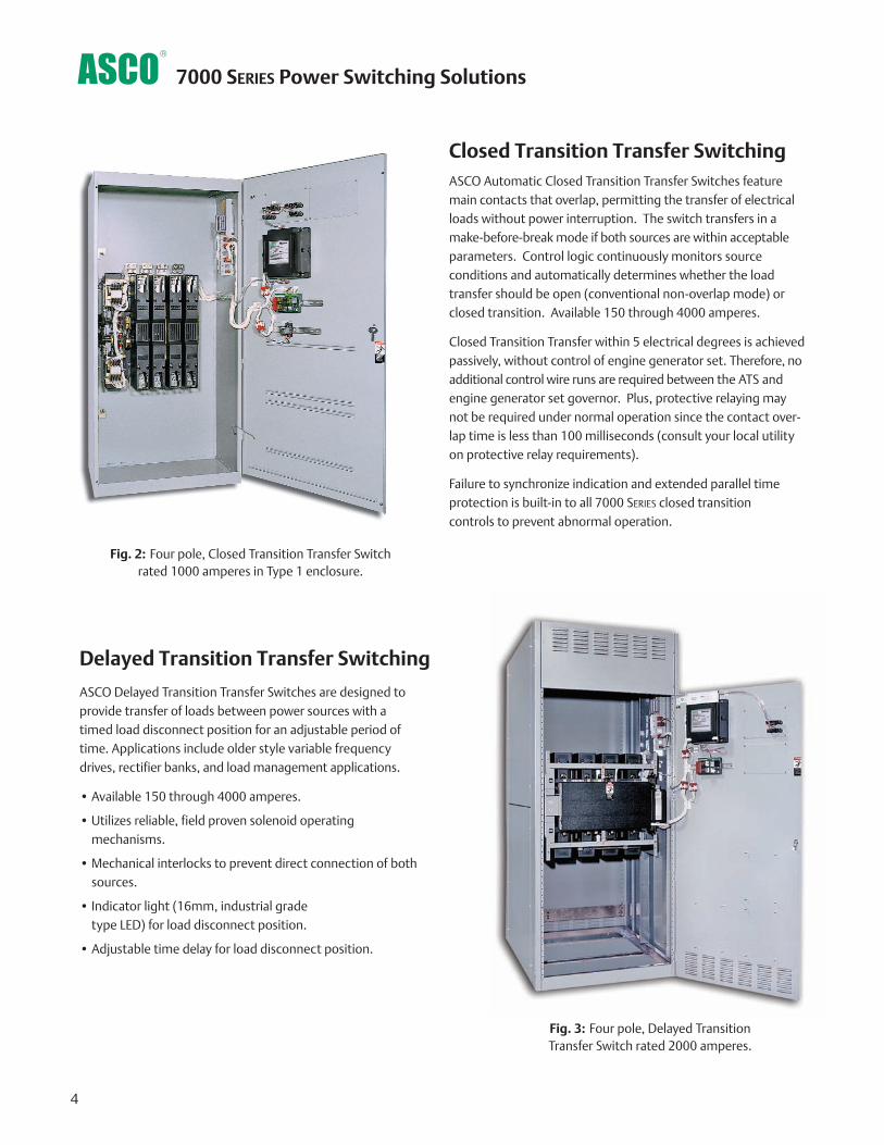
Delayed Transition Transfer Switching
Fig. 3: Four pole, Delayed Transition Transfer Switch rated 2000 amperes.
ASCO Delayed Transition Transfer Switches are designed toprovide transfer of loads between power sources with atimed load disconnect position for an adjustable period oftime. Applications include older style variable frequencydrives, rectifier banks, and load management applications.
• Available 150 through 4000 amperes.
• Utilizes reliable, field proven solenoid operating mechanisms.
• Mechanical interlocks to prevent direct connection of bothsources.
• Indicator light (16mm, industrial grade type LED) for load disconnect position.
• Adjustable time delay for load disconnect position.
Closed Transition Transfer SwitchingASCO Automatic Closed Transition Transfer Switches featuremain contacts that overlap, permitting the transfer of electricalloads without power interruption. The switch transfers in amake-before-break mode if both sources are within acceptableparameters. Control logic continuously monitors source conditions and automatically determines whether the loadtransfer should be open (conventional non-overlap mode) orclosed transition. Available 150 through 4000 amperes.
Closed Transition Transfer within 5 electrical degrees is achievedpassively, without control of engine generator set. Therefore, noadditional control wire runs are required between the ATS andengine generator set governor. Plus, protective relaying maynot be required under normal operation since the contact over-lap time is less than 100 milliseconds (consult your local utilityon protective relay requirements).
Failure to synchronize indication and extended parallel timeprotection is built-in to all 7000 SERIES closed transition controls to prevent abnormal operation.
Fig. 2: Four pole, Closed Transition Transfer Switchrated 1000 amperes in Type 1 enclosure.
4
7000 SERIES Power Switching Solutions
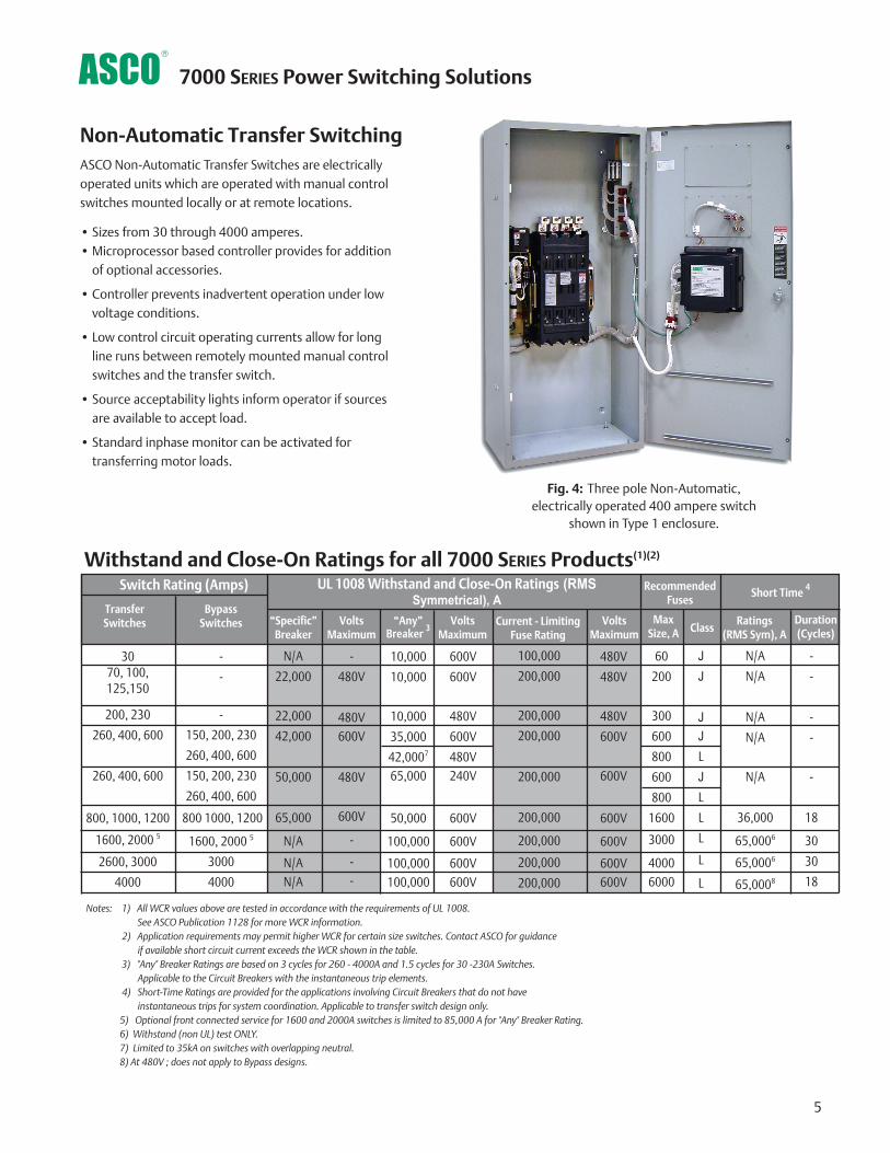
Non-Automatic Transfer SwitchingASCO Non-Automatic Transfer Switches are electricallyoperated units which are operated with manual controlswitches mounted locally or at remote locations.
• Sizes from 30 through 4000 amperes.• Microprocessor based controller provides for addition
of optional accessories.
• Controller prevents inadvertent operation under lowvoltage conditions.
• Low control circuit operating currents allow for longline runs between remotely mounted manual controlswitches and the transfer switch.
• Source acceptability lights inform operator if sourcesare available to accept load.
• Standard inphase monitor can be activated fortransferring motor loads.
Fig. 4: Three pole Non-Automatic, electrically operated 400 ampere switch
shown in Type 1 enclosure.
5
7000 SERIES Power Switching Solutions
-
-
-
150, 200, 230
260, 400, 600
150, 200, 230
260, 400, 600
800 1000, 1200
1600, 2000 5
3000
4000
-
-
-
-
-
18
30
30
18
Withstand and Close-On Ratings for all 7000 SERIES Products(1)(2)
Notes: 1) All WCR values above are tested in accordance with the requirements of UL 1008. See ASCO Publication 1128 for more WCR information.
2) Application requirements may permit higher WCR for certain size switches. Contact ASCO for guidance if available short circuit current exceeds the WCR shown in the table.
3) "Any" Breaker Ratings are based on 3 cycles for 260 - 4000A and 1.5 cycles for 30 -230A Switches. Applicable to the Circuit Breakers with the instantaneous trip elements.
4) Short-Time Ratings are provided for the applications involving Circuit Breakers that do not have instantaneous trips for system coordination. Applicable to transfer switch design only.
5) Optional front connected service for 1600 and 2000A switches is limited to 85,000 A for "Any" Breaker Rating.6) Withstand (non UL) test ONLY.7) Limited to 35kA on switches with overlapping neutral.8) At 480V ; does not apply to Bypass designs.
3070, 100, 125,150
200, 230
260, 400, 600
260, 400, 600
800, 1000, 1200
1600, 2000 5
2600, 3000
4000
100,000
200,000
200,000
200,000
200,000
200,000
200,000
200,000
200,000
JJ
JJL
JL
L
L
L
L
10,000
10,000
10,000
35,000
42,0007
65,000
50,000
100,000
100,000100,000
N/A
N/A
N/A
N/A
N/A
36,000
65,0006
65,0006
65,0008
Ratings(RMS Sym), A
Duration(Cycles)
“Specific” Breaker
N/A
22,000
22,000
42,000
50,000
65,000
N/A
N/AN/A
60
200
300
600
800
600
800
1600
3000
40006000
Current - LimitingFuse Rating
BypassSwitches
Transfer Switches
Switch Rating (Amps)
“Any” Breaker 3
VoltsMaximum
-
480V
480V600V
480V
600V
-
--
UL 1008 Withstand and Close-On Ratings (RMSSymmetrical), A
VoltsMaximum
600V
600V
480V
600V
480V240V
600V
600V
600V600V
VoltsMaximum
480V
480V
480V
600V
600V
600V
600V
600V600V
Max Size, A
RecommendedFuses
Class
Short Time 4

Automatic Transfer Bypass-Isolation Switching
ASCO Automatic Transfer & Bypass-Isolation Switches areavailable in open transition, closed transition and delayedtransition designs. The bypass and isolation features allowpower transfer switches to be inspected, tested, andmaintained without any interruption of power to the load.
• Available 150 to 4000 amperes.
• Allows bypass-isolation without load interruption.
• Bypass switch and transfer switch have identical electrical
ratings.
• Heavy duty mechanical interlocks prevent undesirable
operation.
• Bypass contacts carry current only during bypass mode.
• Transfer switch is drawout design for ease of maintenance.
• Bypass and isolation handles are permanently mounted.The bypass switch has dead front quick-make, quick-breakoperation for transferring of loads between live sources.
• Bypass switch is fully rated for use as a manual 3-position transfer switch.
• Bypass and isolation functions are simple, requiring a total oftwo operating handles.
• No toggle switches, push buttons, selector switches or leversare required for bypass-isolation operation.
• Mechanical indicators show bypass and transfer switchpositions.
• 800 -1200 ampere available in shallow depth, front connectedor rear connected designs.
Fig. 6: Three Pole 7000SERIES AutomaticBypass-Isolation
Transfer Switch Rated1000 Amps
Transfer Switch Drawout Features (150-3000 amperes)
• Automatic secondary disconnectsremove all control power as switch iswithdrawn.
• Drawout carriage provides for easytransfer switch maintenance and/orremoval via commercially availablebreaker hoists.
• Optional transfer switch lifting yoke kit available
• Optional automatic shutters whichclose when the transfer switch is withdrawn to provide bus isolation,specify accessory 82C.(1000-3000Aonly)
AutomaticSecondary
Disconnects
AutomaticShutters
(optional)
Fig. 8: Bypass-Isolation Transfer Switch secondary disconnects and
optional automatic shutters.
6
Self Aligning
Jaws
Fig. 9: Bypass-IsolationTransfer Switch self
aligning power jaws.
7000 SERIES Power Switching Solutions
Fig. 5: J-Design Bypass-Isolation
Transfer Switch Rated600 Amps
Fig. 7: Three Pole 7000SERIES AutomaticBypass-Isolation
Transfer Switch Rated3000 Amps
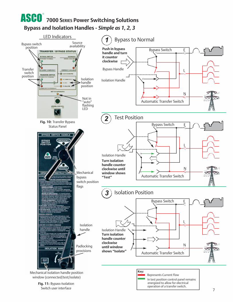
Push in bypass handle and turn it counter clockwise
7
7000 SERIES Power Switching Solutions
Bypass Switch E
L
N
Automatic Transfer Switch
Bypass Switch E
L
N
Automatic Transfer Switch
Bypass Switch E
L
N
Automatic Transfer Switch
Turn isolation handle counter clockwise until window shows“Test”
Mechanical isolation handle position window (connected/test/isolate)
Padlockingprovisions
Mechanicalbypass switch positionflags
Turn isolationhandle counterclockwise until windowshows “Isolate”
Bypass to Normal
Test Position
Isolation Position
Isolation Handle
Bypass Handle
Isolation Handle
Isolation HandleIsolationhandle
Bypass and Isolation Handles - Simple as 1, 2, 3
1
2
3
Key:Represents Current Flow
In test position control panel remains energized to allow for electrical operation of a transfer switch.
Fig. 11: Bypass-IsolationSwitch user interface
Source availability
Bypass switchposition
Transfer switch
positionIsolationhandleposition
Not in“auto”flashingLED
Fig. 10: Transfer BypassStatus Panel
LED Indicators
Optional Features• Enclosures - Secure Double Door
- UL Type 3R w/strip heater & thermostat
- UL Type 4 or 4X
- UL Type 12
• Connections
- Crimp lugs
- Bus Riser on Normal, Emergency or Load
• Protective Relays/Metering
- Accessory 85L , see page 15
• Surge Suppression- Accessory 73, 80KA Surge protector (see pg. 14)
• Communications- ASCO 72A Communication interface module- ASCO POWERQUEST®, see page 18- ASCO 5500 SERIES Thin Web Server for internet
connection , see page 21
• Additional Breaker(s)- Circuit Breaker on Emergency- Load Distribution Panel
• Optional high AIC ratings on breakers
Consult ASCO for additional features
7000 SERIES Service Entrance Power Transfer Switches
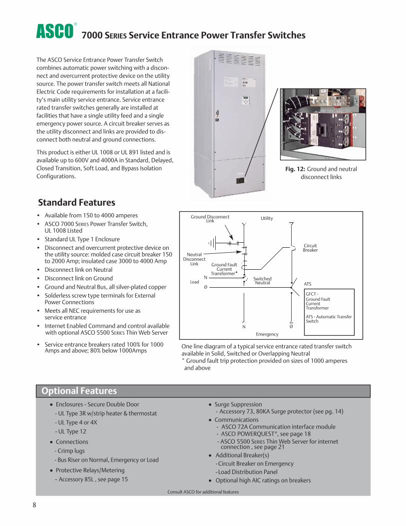
The ASCO Service Entrance Power Transfer Switchcombines automatic power switching with a discon-nect and overcurrent protective device on the utilitysource. The power transfer switch meets all NationalElectric Code requirements for installation at a facili-ty’s main utility service entrance. Service entrancerated transfer switches generally are installed atfacilities that have a single utility feed and a singleemergency power source. A circuit breaker serves asthe utility disconnect and links are provided to dis-connect both neutral and ground connections.
This product is either UL 1008 or UL 891 listed and isavailable up to 600V and 4000A in Standard, Delayed,Closed Transition, Soft Load, and Bypass IsolationConfigurations.
8
Standard Features• Available from 150 to 4000 amperes• ASCO 7000 SERIES Power Transfer Switch,
UL 1008 Listed • Standard UL Type 1 Enclosure• Disconnect and overcurrent protective device on
the utility source: molded case circuit breaker 150 to 2000 Amp; insulated case 3000 to 4000 Amp
• Disconnect link on Neutral• Disconnect link on Ground• Ground and Neutral Bus, all silver-plated copper• Solderless screw type terminals for External
Power Connections• Meets all NEC requirements for use as
service entrance• Internet Enabled Command and control available
with optional ASCO 5500 SERIES Thin Web Server
• Service entrance breakers rated 100% for 1000Amps and above; 80% below 1000Amps
NeutralDisconnect
Link
Ground DisconnectLink
Ground FaultCurrent
Transformer**
Utility
CircuitBreaker
ATS
Emergency
LoadN
Ø
N Ø
GFCT - Ground FaultCurrent Transformer
ATS - Automatic TransferSwitch
SwitchedNeutral
One line diagram of a typical service entrance rated transfer switchavailable in Solid, Switched or Overlapping Neutral* Ground fault trip protection provided on sizes of 1000 amperes
and above
Fig. 12: Ground and neutral disconnect links
The Example Catalog Number above is 7AUSA3400N5XC (X is used to specify optional accessories).
7000 SERIES Service Entrance Power Transfer Switches
9
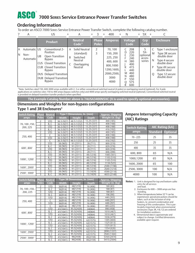
Dimensions and Weights for non-bypass configurationsType 1 and 3R Enclosures4
A Automatic
N Non-Automatic
C Type 1 enclosureM Type 3R secure
double doorN Type 4 secure
double doorP Type 4X secure
double doorQ Type 12 secure
double door
US Conventional 2-Position
UB Open TransitionBypass
CUS Closed TransitionCUB Closed Transition
BypassDUS Delayed TransitionDUB Delayed Transition
Bypass
A Solid Neutral(standard)
B SwitchedNeutral
C OverlappingNeutral
23
70, 100150, 200225, 250400, 600800,1000
1200,1600,2000,2500,
30004000
C 208D 220E 230F 240H 380J 400K 415L 440M 460N 480P 550Q 575R 600
55X-
optionalacces-sories
Ordering Information
Product NeutralCode*
PhasePoles
VoltageCode
GrpCode
EnclosureAmperes
To order an ASCO 7000 SERIES Service Entrance Power Transfer Switch, complete the following catalog number.7 A US + A + 3 + 400 + N + 5X + C
*Note. Switches rated 150, 600-3000 amps available with 2, 3 or either conventional switched neutral (4 poles) or overlapping neutral (optional). For 4 poleapplications on switches rates 150 to 400 amps (bypass switches only) and 4000 amps specify overlapping switched neutral (optional). Conventional switched neutralis provided on delayed transition transfer products when specified.
Ampere Interrupting Capacity(AIC) Ratings
70 - 225 25 35
250 25 35
400 35 35
600, 800 65 N/A
1000,1200 65 N/A
1600, 2000 65 100
2500, 3000 100 N/A
4000 100 N/A
StandardSwitch Rating
amps Optional
AIC Rating (kA)
22332233223322333333
Switch Ratingamps
Phase Poles
Neutral Code
Type 1 Dimensions, In. (mm)Width Height Depth
Approx. ShippingWeight Lb. (kg)
70, 100 ,150, 200, 225
250, 400
6001, 8001
10001, 12001
16001, 20001
25001, 30001
STDB, CSTDB, CSTD
CSTD
CSTDB, CSTDB, CSTDB, CSTDB, CSTDB, CSTDB, C
36.5 (927)36.5 (927)36.5 (927)36.5 (927)36.5 (927)36.5 (927)36.5 (927)36.5 (927)
38 (965)38 (965)38 (965)38 (965)38 (965)38 (965)38 (965)38 (965)38 (965)38 (965)38 (965)38 (965)
48.5 (1232)48.5 (1232)48.5 (1232)48.5 (1232)48.5 (1232)48.5 (1232)48.5 (1232)48.5 (1232)
91 (2311)91 (2311)91 (2311)91 (2311)91 (2311)91 (2311)91 (2311)91 (2311)91 (2311)91 (2311)91 (2311)91 (2311)
13.25 (337)13.25 (337)13.25 (337)13.25 (337)13.25 (337)13.25 (337)13.25 (337)13.25 (337)
28 (711)28 (711)28 (711)28 (711)
48 (1218)48 (1218)48 (1218)48 (1218)48 (1218)48 (1218)72 (1829)72 (1829)
400 (185)408 (188)408 (188)416 (192)400 (185)408 (188)408 (188)416 (192)800 (370)820 (378)820 (378)846 (390)
1085 (501)1105 (510)1105 (510)1134 (523)
2590 (1198)2640 (1218)4590 (2118)4655 (2148)
22332233223322333333
70, 100 ,150, 200, 225
250, 400
6001, 8001
10001, 12001
16001, 20001
25001, 30001
STDB, CSTDB, CSTD
CSTD
CSTDB, CSTDB, CSTDB, CSTDB, CSTDB, CSTDB, C
36(914)36(914)36(914)36(914)36(914)36(914)36(914)36(914)
41(1041)41(1041)41(1041)41(1041)41(1041)41(1041)41(1041)41(1041)41(1041)41(1041)41(1041)41(1041)
48(1219)48(1219)48(1219)48(1219)48(1219)48(1219)48(1219)48(1219)
95.5(2426)95.5(2426)95.5(2426)95.5(2426)95.5(2426)95.5(2426)95.5(2426)95.5(2426)95.5(2426)95.5(2426)
96(2438)96(2438)
16 (406)16 (406)16 (406)16 (406)16 (406)16 (406)16 (406)16 (406)34(864)34(864)34(864)34(864)
62(1575)62(1575)62(1575)62(1575)62(1575)62(1575)85(2159)85(2159)
180 (83)188 (87)188 (87)196 (90)
440 (203)448 (207)448 (207)485 (225)990 (458)
1010 (467)1010 (467)1036 (479)1305 (604)1325 (613)1325 (613)1354 (626)
2890 (1337)2940 (1360)5350 (2474)5415 (2504)
Notes: 1. Unit is designed for top and bottom cable entry for all services and load.
2. Enclosures for 600 – 3000 amps are freestanding.
3. When temperatures below 32° F can beexperienced, special precautions should betaken, such as the inclusion of stripheaters, to prevent condensation andfreezing of this condensation. This is par-ticularly important when environmentalenclosures (Type 3R, 4 & 12) are orderedfor installation outdoors.
4. Dimensional data is approximate and subject to change. Certified dimensions available upon request.
Switch Ratingamps
Phase Poles
Neutral Code
Type 3R Dimensions, In. (mm)Width Height Depth
Approx. ShippingWeight Lb. (kg)
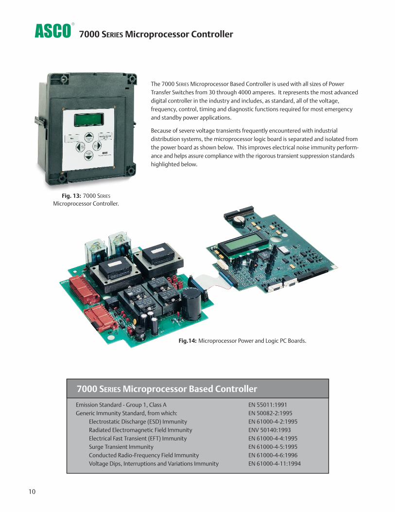
The 7000 SERIES Microprocessor Based Controller is used with all sizes of PowerTransfer Switches from 30 through 4000 amperes. It represents the most advanceddigital controller in the industry and includes, as standard, all of the voltage,frequency, control, timing and diagnostic functions required for most emergencyand standby power applications.
Because of severe voltage transients frequently encountered with industrial distribution systems, the microprocessor logic board is separated and isolated fromthe power board as shown below. This improves electrical noise immunity perform-ance and helps assure compliance with the rigorous transient suppression standardshighlighted below.
10
Fig.14: Microprocessor Power and Logic PC Boards.
Fig. 13: 7000 SERIES
Microprocessor Controller.
7000 SERIES Microprocessor Based Controller
Emission Standard - Group 1, Class A EN 55011:1991Generic Immunity Standard, from which: EN 50082-2:1995
Electrostatic Discharge (ESD) Immunity EN 61000-4-2:1995Radiated Electromagnetic Field Immunity ENV 50140:1993Electrical Fast Transient (EFT) Immunity EN 61000-4-4:1995Surge Transient Immunity EN 61000-4-5:1995Conducted Radio-Frequency Field Immunity EN 61000-4-6:1996 Voltage Dips, Interruptions and Variations Immunity EN 61000-4-11:1994
7000 SERIES Microprocessor Controller
Voltage and Frequency Sensing• 3-Phase under and over voltage settings on normal
and emergency sources.
• Under and over frequency settings on normal and emergency.
• True RMS Voltage Sensing with +/- 1% accuracy;Frequency Sensing Accuracy is +/- 0.2%.
• Selectable settings: single or three phase voltage sensing on normal and emergency; 50 or 60Hz.
• Phase sequence sensing for phase sensitive loads.
• Voltage unbalance detection between phases.
Status and Control Features• Output contact (N/O or N/C) for engine-start signals.
• Selection between “commit/no-commit” on transfer to emergency after engine start and normal restoresbefore transfer.
• Advanced inphase algorithm which automatically measures the frequency difference between the two sources andinitiates transfer at appropriate phase angles to minimizedisturbances when transferring motor loads.
• Event log displays 99 logged events with the time anddate of the event, event type and event reason.
• Output signals for remote indication of normal and emer-gency source acceptability
• Statistical ATS/System monitoring data screens which provide:
• Total number of ATS transfers.
• Number of ATS transfers caused by power source failure.
• Total number of days ATS has been in operation.
• Total number of hours that the normal and emergencysources have been available.
Time Delays• Engine start time delay - delays engine starting signal to
override momentary normal source outages - adjustable0 to 6 seconds.
• Transfer to emergency time delay - adjustable 0 to 60minutes.
• Emergency source stabilization time delay to ignore momentary transients during initial generator set loading - adjustable 0 to 6 seconds.
• Retransfer to normal time delay with two settings:
• Power failure mode - 0 to 60 minutes.
• Test mode - 0 to 10 hours.
• Unloaded running time delay for engine cooldown -adjustable 0 to 60 minutes.
• Pre and post transfer signal time delay for selective load disconnect with a programmable bypass on sourcefailures - adjustable 0 to 5 minutes. This signal can beused to drive a customer furnished relay, or for (2) sets ofdouble throw contacts rated 3 amps at 480 volts AC,specify ASCO optional accessory 31Z.
• Fully programmable engine exerciser with seven independent routines to exercise the engine generator,with or without loads, on a daily, weekly, bi-weekly ormonthly basis.
• Contains all alarm signals, logic and time delays for use with closed transition switches.
• Insynch time delay - 0 to 3 seconds.
• Failure to synchronize - 1 to 5 minutes.
• Extended parallel - 0.1 to 1.0 seconds.
• Delayed transition load disconnect time delay - adjustable 0 to 5 minutes.
11
7000 SERIES Microprocessor Controller
Features
• Digital microprocessor.
• Touch pad programming of features and settings without the need for meters, or variable power supplies.
• Sixteen (16) selectable operating voltages available in asingle Controller.
• On-board diagnostics provide control panel and ATS sta-tus information to analyze system performance.
• Displays and counts down active timing functions.
• Selectable multi-language display (English, German, Portuguese, Spanish, or French. Forothers contact ASCO).
• Password protection to prevent unauthorized tamperingof settings.
• Remote monitoring and control with ASCOPOWERQUEST® communications products. Specify optional accessory 72A or 72E.
• Load shed option for SYNCHROPOWER® bus optimization applications. Specify optional accessory 30B.
• Historical event log
• Statistical ATS systems monitoring information

12
The 7000 SERIES microprocessor controller is a Power Control Center whichallows the user to easily access detailed information on: system status; powersource parameters; voltage, frequency and time delay settings; optionalfeature settings; historical event log; and system diagnostics. A four line, (20)character LCD has a backlit display which enables easy viewing under allconditions. The user can navigate through all screens using only six buttons,which also allows selection of: (18) different source parameter settings; (16)standard time delays; (12) standard feature settings; up to seven independentengine exercise routines; and even the language (English, German, Spanish,French, etc.) which appears on the display.
Since the Power Control Center must be visible and operable through the enclosure door, it has been qualified for use in industrial and outdoorapplications. This includes installation in Type 3R (outdoor/rainproof), 4 (weatherproof) and 12 (indoor/industrial) enclosures.
7000 SERIES Power Control Center
Control Switches and Indicating Lights for Conventional 2-Position Switches
Control Switches and Indicating Lights for Closed Transition Switches
Fig. 15: 7000 SERIES User Controls and Indicators.
Fig. 17: 7000 SERIES
Power Control Center.
Fig. 16: 7000 SERIES User Controls and Indicators.
• Switch position indicating lights (16 mm, industrial grade LEDs).
• Source acceptability indicating lights with true indication of the acceptability of each source, as determined by the voltage, frequency,voltage unbalance, and phase sequence settings of the control panel(16mm, industrial grade LEDs).
• Three position (16mm, industrial grade type) selector switch:
• Automatic: Normal maintained position.
• Test: Momentary position to simulate normal source failure for system test function.
• Reset Delay Bypass: Momentary position to bypass transfer and re-transfer time delay.
• Extended Parallel Time - Provides visual indication when thepre-set extended parallel time has been exceeded. The controlsautomatically open the emergency or normal main contacts.Separate contact also available to shunt trip external breaker.
• Failure To Synchronize - Visually displays a failure to synchronizealarm if the time delay settings is exceeded, during closed transition transfer operation.
• TS Locked Out - Prevents transfer in either direction if theextended parallel time is exceeded.
• Alarm Reset - Resets extended parallel and failure tosynchronize alarms.
• Closed Transition Bypass - Pushbutton allows transfer betweensources in an open transition mode.
7000 SERIES User Controls and Indicators

Normal SourceVab=480V....................ABCVbc=480V.........Vunbal=1%Vca=480V................60.0Hz
P1..................Engine.ExerciserEnable:.....Yes....WLoad:....YesStart:19h30. ALL MONRun.Time:...............2h15min
16.AUG02/95..........13h10:17Eng.Start...............NormFail.15.AUG02/95...........13h10:25Xfer.N>E................................
Normal OK
TD.Engine.Cooldown:4min15s
Normal OK
Load on Normal
Normal VoltageDropout.............85%.408VPickup...............90%.432VO.V. Trip.........110%.528V
Displays voltage for each phase, frequency, phase rotation and voltage unbalance for both
normal and emergency sources.
Provides voltage and frequency setting values for normal and emergency sources. Voltage pick-up,
dropout and trip settings are set in percentage of nominalvoltage and are also displayed in rms voltage values.
Seven independent programs, load/no load selection, flexible run times and daily, weekly,
bi-weekly and monthly exercise routines.
Active time delay status displays time remaining until next control event.
TD N>E Xfer SignalBypass if N Fail: NoPre Xfer: 0 min 20S
Post Xfer: 0 min 20S
Provides direct reading display for setting time delays.
Displays system status in clear, concise language. Message shown indicates normal source is acceptable
and the load is connected to the normal source.
Displays detailed information for last 99 events, including time of occurrence, length of event,
date and reason for event.
ATS StatisticsATS Total Xfers: 46
SRC Fail Tot Xfers: 20Days Energized: 36.5
Instant availability of statistical information on total number ofATS transfers, number of transfers caused by power failures and
total days controller has been energized, plus more.
13
Source Status
Time Delay Status
Voltage and Frequency Settings Time Delay Settings
Engine Exerciser
Historical Event Log
System Status
ATS Statistics
Emerg OK
Waiting for In-Sync -45o 0.02Hz
Displays the relative phase angle between sources and frequency differential to indicate
the controller is awaiting an inphase condition.
Shed Load
Direction: From EInphase: No TD/0.25
Standard features can be activated with the keypad. As anexample, when enabled, the “shed load” option causes the
transfer switch to transfer the load off of the specified source.If desired, the load shed transfer can be made inphase.
Inphase Transfer Mode
Feature Settings
Status
Settings
Data Logging
7000 SERIES Power Control Center Screens
14
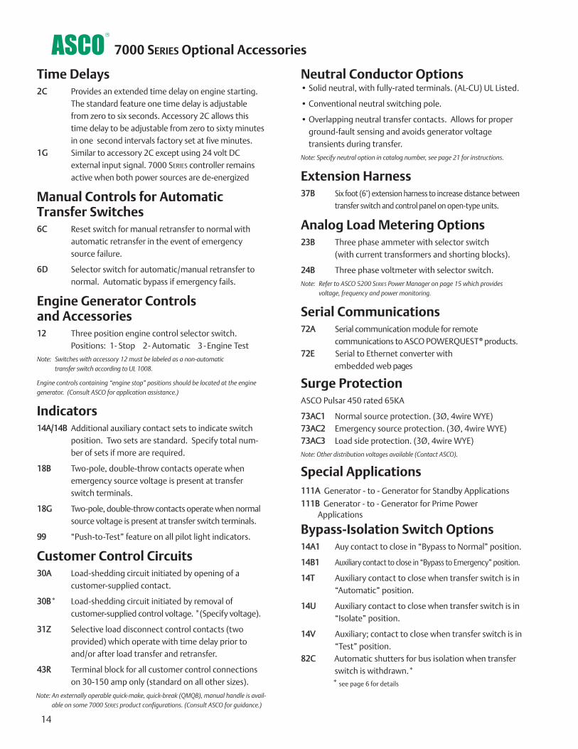
Time Delays2C Provides an extended time delay on engine starting.
The standard feature one time delay is adjustablefrom zero to six seconds. Accessory 2C allows thistime delay to be adjustable from zero to sixty minutesin one second intervals factory set at five minutes.
1G Similar to accessory 2C except using 24 volt DCexternal input signal. 7000 SERIES controller remainsactive when both power sources are de-energized
Manual Controls for Automatic Transfer Switches6C Reset switch for manual retransfer to normal with
automatic retransfer in the event of emergencysource failure.
6D Selector switch for automatic/manual retransfer tonormal. Automatic bypass if emergency fails.
Engine Generator Controls and Accessories12 Three position engine control selector switch.
Positions: 1- Stop 2- Automatic 3 - Engine Test
Note: Switches with accessory 12 must be labeled as a non-automatic transfer switch according to UL 1008.
Engine controls containing “engine stop” positions should be located at the enginegenerator. (Consult ASCO for application assistance.)
Indicators14A/14B Additional auxiliary contact sets to indicate switch
position. Two sets are standard. Specify total num-ber of sets if more are required.
18B Two-pole, double-throw contacts operate whenemergency source voltage is present at transferswitch terminals.
18G Two-pole, double-throw contacts operate when normalsource voltage is present at transfer switch terminals.
99 “Push-to-Test” feature on all pilot light indicators.
Customer Control Circuits30A Load-shedding circuit initiated by opening of a
customer-supplied contact.
30B* Load-shedding circuit initiated by removal of customer-supplied control voltage. *(Specify voltage).
31Z Selective load disconnect control contacts (two provided) which operate with time delay prior toand/or after load transfer and retransfer.
43R Terminal block for all customer control connectionson 30-150 amp only (standard on all other sizes).
Neutral Conductor Options• Solid neutral, with fully-rated terminals. (AL-CU) UL Listed.
• Conventional neutral switching pole.
• Overlapping neutral transfer contacts. Allows for properground-fault sensing and avoids generator voltage transients during transfer.
Note: Specify neutral option in catalog number, see page 21 for instructions.
Extension Harness37B Six foot (6’) extension harness to increase distance between
transfer switch and control panel on open-type units.
Analog Load Metering Options23B Three phase ammeter with selector switch
(with current transformers and shorting blocks).
24B Three phase voltmeter with selector switch.
Note: Refer to ASCO 5200 SERIES Power Manager on page 15 which providesvoltage, frequency and power monitoring.
Serial Communications72A Serial communication module for remote
communications to ASCO POWERQUEST® products.72E Serial to Ethernet converter with
embedded web pages
Surge ProtectionASCO Pulsar 450 rated 65KA
73AC1 Normal source protection. (3Ø, 4wire WYE)73AC2 Emergency source protection. (3Ø, 4wire WYE)73AC3 Load side protection. (3Ø, 4wire WYE)
Note: Other distribution voltages available (Contact ASCO).
Special Applications111A Generator - to - Generator for Standby Applications
111B Generator - to - Generator for Prime Power Applications
Bypass-Isolation Switch Options14A1 Auy contact to close in “Bypass to Normal” position.
14B1 Auxiliary contact to close in “Bypass to Emergency” position.
14T Auxiliary contact to close when transfer switch is in“Automatic” position.
14U Auxiliary contact to close when transfer switch is in“Isolate” position.
14V Auxiliary; contact to close when transfer switch is in“Test” position.
82C Automatic shutters for bus isolation when transfer switch is withdrawn.*
* see page 6 for details
Note: An externally operable quick-make, quick-break (QMQB), manual handle is avail-able on some 7000 SERIES product configurations. (Consult ASCO for guidance.)
7000 SERIES Optional Accessories
15
Optional Configurations and Connection Arrangements
Connected To: With Display Without DisplayLoad Acc. 85L Acc. 75LNormal Acc. 85N Acc. 75NEmergency Acc. 85M Acc. 75MLoad (BPS only) Acc. 85R* Acc. 75R*
Add suffix “A” to above designations if neutral conductor monitoring is required.
Note: Accessory 75 and 85 includes component mounting, CTs, shorting blocks and all necessary interwiring.
*Bypass & isolation switch contacts wired to discrete Power Manager inputs.
7000 SERIES Optional Accessories
Power Metering• Voltage:
Line - Line: VAB, VBC, VCA, VAVERAGELine - Neutral: VAN, VBN, VCN, VAVERAGE
• Frequency: 45.0 to 66.0 Hertz
• Current: IA, IB, IC, IAVERAGE
• Unbalance %: Voltage, Amps
• Real Power: KWA, KWB, KWC, KWNET
• Reactive Power: KVARA, KVARB, KVARC, KVARNET
• Apparent Power: KVAA, KVAB, KVAC, KVANET
• Real Energy: KWHIMPORT, KWHEXPORT, KWHNET
• Reactive Energy: KVARHIMPORT, KVARHEXPORT,KVARHNET
• Power Factor: PFA, PFB, PFC, PFNET
Data Access• Eight digital inputs, four relay outputs.
• Input/Output 15-character, user definable screen display for identification of input/output signals.
Communications• RS485 (2) or (4) wire serial capability.
• Includes Modbus RTU.
• Ethernet compatible when combined with5150 Connectivity Module (72E).
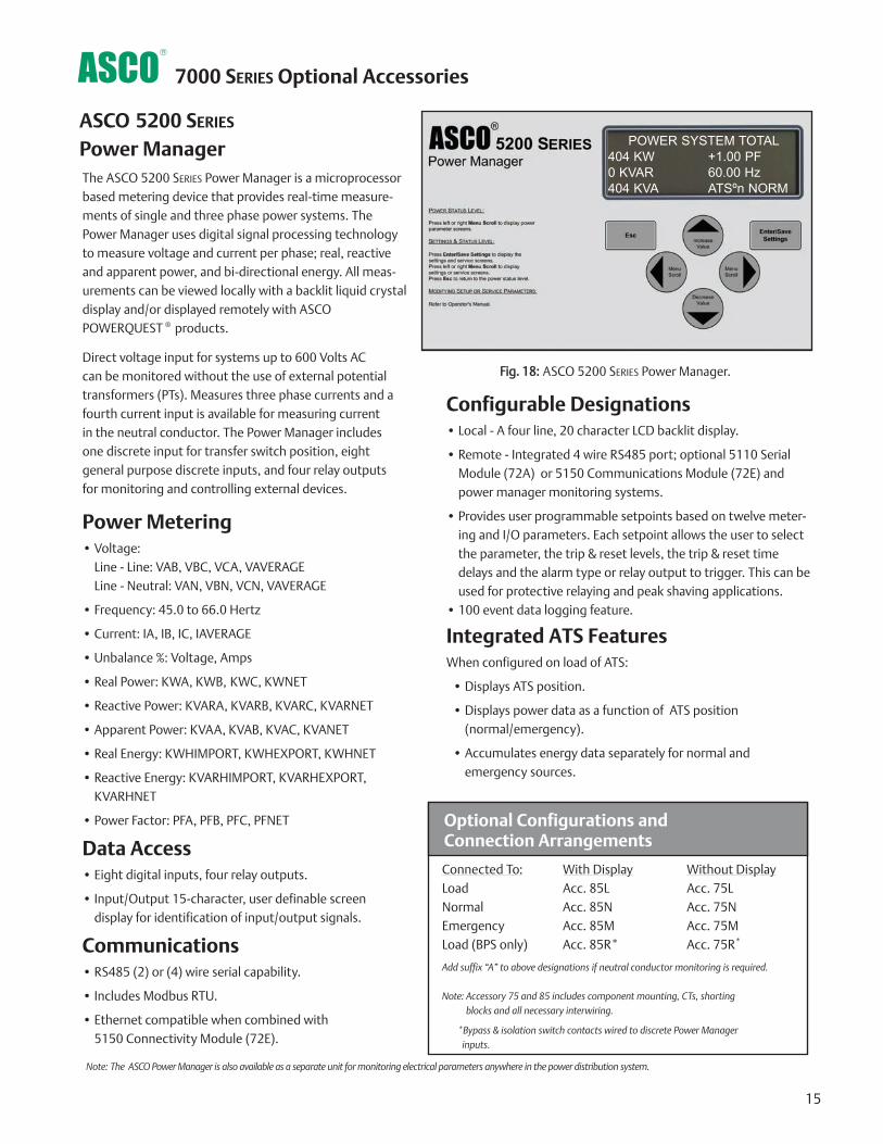
Fig. 18: ASCO 5200 SERIES Power Manager.
Configurable Designations• Local - A four line, 20 character LCD backlit display.
• Remote - Integrated 4 wire RS485 port; optional 5110 SerialModule (72A) or 5150 Communications Module (72E) andpower manager monitoring systems.
• Provides user programmable setpoints based on twelve meter-ing and I/O parameters. Each setpoint allows the user to selectthe parameter, the trip & reset levels, the trip & reset timedelays and the alarm type or relay output to trigger. This can beused for protective relaying and peak shaving applications.
• 100 event data logging feature.
Integrated ATS FeaturesWhen configured on load of ATS:
• Displays ATS position.
• Displays power data as a function of ATS position (normal/emergency).
• Accumulates energy data separately for normal and emergency sources.
ASCO 5200 SERIES
Power ManagerThe ASCO 5200 SERIES Power Manager is a microprocessorbased metering device that provides real-time measure-ments of single and three phase power systems. ThePower Manager uses digital signal processing technologyto measure voltage and current per phase; real, reactiveand apparent power, and bi-directional energy. All meas-urements can be viewed locally with a backlit liquid crystaldisplay and/or displayed remotely with ASCOPOWERQUEST ® products.
Direct voltage input for systems up to 600 Volts AC can be monitored without the use of external potentialtransformers (PTs). Measures three phase currents and afourth current input is available for measuring current in the neutral conductor. The Power Manager includesone discrete input for transfer switch position, eightgeneral purpose discrete inputs, and four relay outputsfor monitoring and controlling external devices.
Note: The ASCO Power Manager is also available as a separate unit for monitoring electrical parameters anywhere in the power distribution system.
POWER SYSTEM TOTAL404 KW +1.00 PF0 KVAR 60.00 Hz404 KVA ATSºn NORM

16
7000 SERIES Power Monitoring & Control
Features• Monitors and controls Power Transfer Switches and Engine Generators
• Monitors normal and emergency voltages and frequency
• Indicates transfer switch position and source availability
• Provides transfer and re-transfer of loads for system testing
• View normal and emergency voltage and frequency settings
• View transfer switch time-delay settings
• Provides transfer switch rating and identification
• Automatic paging notifies personnel, by e-mail or text message, of selected system alarms
• View current, power and power factor with ASCO Power Managers Connected to the System
• View transfer switch event log
• Provides transfer switch test schedule
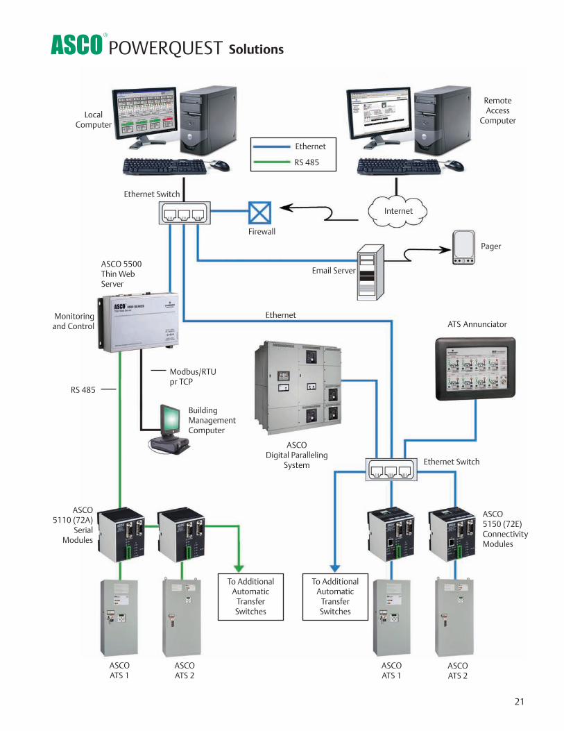
ASCO POWERQUEST SolutionsASCO POWERQUEST® communications products allow for the monitoring and control of power transferswitches in your Emergency or Standby Power Distribution System. Local Area networks and Remote networksare supported with either single or multiple points of access, and web-enabled communications allow accessto your power system from anywhere around the world.
Typical Network Architecture
ASCOATS 1
ASCOATS 2
ASCO 5200Power Manager
Generator 2
RS-485
ASCO 5110 (72A) Serial Modules
ASCO 5110 (72A) Serial Modules
ASCOATS 3
ASCOATS 4
ASCOPOWERQUEST®
32.15 Software
To AdditionalAutomatic
Transfer Switches
ASCO 5200Power Manager
Generator 1
ASCO 5150 (72E) Connectivity Module
ASCO 5150(72E)
ConnectivityModule
To AdditionalAutomatic
Transfer Switches
RS-485
EthernetSwitch

17
7000 SERIES Power Monitoring
Fig. 21: ASCORemote Annuciator
Fig. 19: Serial Module 72A
Fig. 20: Connectivity Module 72E
5350 Remote AnnunciatorThe ASCO Power Transfer Switch Remote Annunciator is a stand-alone, industrialgrade interface device providing you with the most critical transfer switch statusindication and transfer/retransfer control for up to eight switches. Ethernet technology is built in for faster and more reliable communications. LEDs indicate switch status and position, while separate push buttons individually initiatetransfer switch operation and testing. Transfer switch annunciators can be set up inmultiple locations to monitor various transfer switches, allowing redundant and distributed annunciation.
5110 Serial ModuleThe 5110 Serial Module is used to allow local or remote communications with ASCOPOWERQUEST® communication products.The module is used to connect the 7000 SERIES transfer switches to a serial networkvia an RS-485 interface. The module has two port connectors used for ATS & PowerManager connectivity.The serial connection is accomplished from a 5-pin terminal header/socket block. RS- 485 serial networks allow for up to 32 modules to be set up in a daisy chainconfiguration to connect to POWERQUEST® systems.
5150 Connectivity ModuleThe 5150 Connectivity Module is used to bring several different serial devices thatcommunicate at different baud rates and with different protocols to a commonEthernet media.The module is used to connect 7000 SERIES transfer switches, and ASCO RemoteAnnuciators to a standard Ethernet TCP/IP network with standard 10base T(RJ-45)connectors. The module has customized embedded JAVATM applets (programapplications for an internet browser) for each monitored device that loadsautomatically to a standard Web Browser. The module is designed to communicate with up to 8 clients such as Webapplications (web pages), POWERQUEST® , or third party Modbus devicessimultaneously over an Ethernet connection.
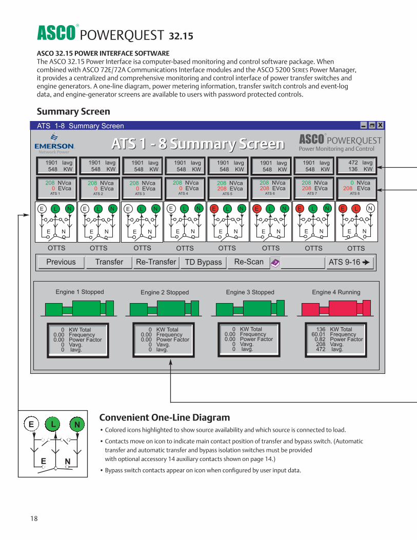
Summary Screen
Convenient One-Line Diagram• Colored icons highlighted to show source availability and which source is connected to load.
• Contacts move on icon to indicate main contact position of transfer and bypass switch. (Automatictransfer and automatic transfer and bypass isolation switches must be provided with optional accessory 14 auxiliary contacts shown on page 14.)
• Bypass switch contacts appear on icon when configured by user input data.
E
E
L N
N
18
32.15
ASCO 32.15 POWER INTERFACE SOFTWAREThe ASCO 32.15 Power Interface isa computer-based monitoring and control software package. When combined with ASCO 72E/72A Communications Interface modules and the ASCO 5200 SERIES Power Manager, it provides a centralized and comprehensive monitoring and control interface of power transfer switches andengine generators. A one-line diagram, power metering information, transfer switch controls and event-logdata, and engine-generator screens are available to users with password protected controls.
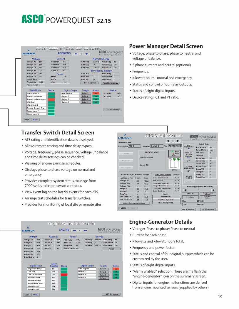
Engine-Generator Details• Voltage: Phase to phase; Phase to neutral
• Current for each phase.
• Kilowatts and kilowatt hours total.
• Frequency and power factor.
• Status and control of four digital outputs which can be customized by the user.
• Status of eight digital inputs.
• “Alarm Enabled” selection. These alarms flash the “engine-generator” icon on the summary screen.
• Digital inputs for engine malfunctions are derived from engine mounted sensors (supplied by others).
Power Manager Detail Screen• Voltage: phase to phase; phase to neutral and
voltage unbalance.
• 3 phase currents and neutral (optional).
• Frequency.
• Kilowatt hours - normal and emergency.
• Status and control of four relay outputs.
• Status of eight digital inputs.
• Device ratings: CT and PT ratio.
Transfer Switch Detail Screen• ATS rating and identification data is displayed.
• Allows remote testing and time delay bypass.
• Voltage, frequency, phase sequence, voltage unbalance and time delay settings can be checked.
• Viewing of engine exercise schedules.
• Displays phase to phase voltage on normal and emergency.
• Provides complete system status message from 7000 series microprocessor controller.
• View event log on the last 99 events for each ATS.
• Arrange test schedules for transfer switches.
• Provides for monitoring of local site or remote sites.
19
32.15
20
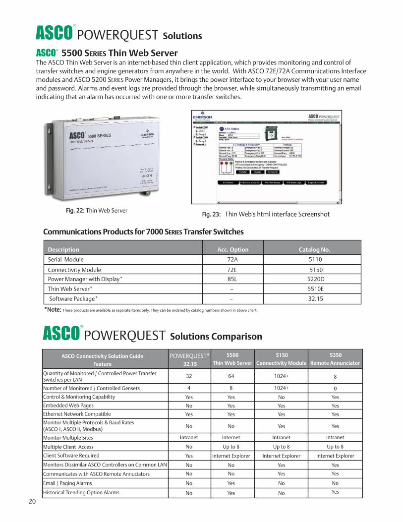
5500 SERIES Thin Web ServerThe ASCO Thin Web Server is an internet-based thin client application, which provides monitoring and control oftransfer switches and engine generators from anywhere in the world. With ASCO 72E/72A Communications Interfacemodules and ASCO 5200 SERIES Power Managers, it brings the power interface to your browser with your user nameand password. Alarms and event logs are provided through the browser, while simultaneously transmitting an emailindicating that an alarm has occurred with one or more transfer switches.
Communications Products for 7000 SERIES Transfer Switches
Description Acc. Option Catalog No.
Serial Module 72A 5110
Connectivity Module 72E 5150
Power Manager with Display* 85L 5220D
Thin Web Server* — 5510E
Software Package* — 32.15
*Note: These products are available as separate items only. They can be ordered by catalog numbers shown in above chart.
ASCO Connectivity Solution Guide
Feature
POWERQUEST®
32.15
5500
Thin Web Server
5150
Connectivity Module
Quantity of Monitored / Controlled Power TransferSwitches per LAN
Number of Monitored / Controlled Gensets
Control & Monitoring Capability
Embedded Web Pages
Ethernet Network Compatible
Monitor Multiple Protocols & Baud Rates(ASCO I, ASCO II, Modbus)
Monitor Multiple Sites
Multiple Client Access
Client Software Required
Monitors Dissimilar ASCO Controllers on Common LAN
Communicates with ASCO Remote Annuciators
Email / Paging Alarms
Historical Trending Option Alarms
32
4
Yes
No
Yes
No
Intranet
No
Yes
No
No
No
No
64
8
Yes
Yes
Yes
No
Internet
Up to 8
Internet Explorer
No
No
Yes
Yes
1024+
1024+
No
Yes
Yes
Yes
Intranet
Up to 8
Internet Explorer
Yes
Yes
No
No
Fig. 22: Thin Web Server
ASCO
Solutions
Solutions Comparison
Fig. 23: Thin Web's html interface Screenshot
5350
Remote Annunciator
8
0
Yes
Yes
Yes
Yes
Intranet
Up to 8
Internet Explorer
Yes
Yes
No
Yes
Internet
Ethernet Switch
RemoteAccess
ComputerLocal
Computer
Firewall
ASCO 5500Thin Web Server
Email Server
Pager
Building ManagementComputer
Ethernet Switch
ASCO 5110 (72A)
SerialModules
ASCO 5150 (72E)ConnectivityModules
ASCOATS 1
ASCOATS 2
Ethernet
ASCODigital Paralleling
System
RS 485
ASCOATS 1
ASCOATS 2
To AdditionalAutomatic
Transfer Switches
To AdditionalAutomatic
Transfer Switches
Ethernet
RS 485
Monitoringand Control
21
ATS Annunciator
Solutions
Modbus/RTUpr TCP

+ + + + + +TSA A 3 400 N 5X C
22
To order an ASCO 7000 SERIES Power Transfer Switch, complete the following catalog number:
The Example Catalog Number above is 7ATSA3400N5XC (X is used to specify optional accessories).
7
*Notes: For 4 pole applications on switches rated 4000 amps specify overlapping switched neutral (optional). Conventional switch neutral is provided on delayed transition transfer products when specified.200 and 230 amp switch limited to 480 volts maximum, on 7ATS, 7CTS and 7DTS only.
Amperes VoltageCode
GrpCode
EnclosureNeutralCode*
Product PhasePoles
115120208220230240380400415440460480550575600
TS
TB
CTS
CTB
DTS
DTB
23
A
N
M
Automatic
Non-Automatic
ManuallyOperated
55X-
optionalacces-sories
---
C
F
G
H
L
M
N
P
Q
---
A
B
C
Conventional 2-Position
OpenTransitionBypass
ClosedTransition
ClosedTransitionBypass
DelayedTransition
DelayedTransitionBypass
No Neutral
Solid Neutral
SwitchedNeutral
OverlappingNeutral
3070
100150200230260400600800
1000120016002000 260030004000
ABCDEF HJKLMNPQR
No enclosure
Type 1 enclosure
Type 3R enclosure
Type 4 enclosure
Type 4X enclosure (stainless steel)
Type 12 enclosure
Type 3R securedouble door
Type 4 securedouble door
Type 4X securedouble door
Type 12 securedouble door
Transfer Switch Configurations7A TS, 7N TS, 7A DTS, 7A CTS, 7N DTS, 7N CTS
Transfer/Bypass Configurations7A TB, 7N TB, 7A DTB, 7A CTB, 7N DTB, 7N CTB
Sizes of UL-Listed Solderless Screw-Type Terminals for External Power Connections
Notes: 1. Unit is designed for top cable entry of emergency and load and bottom entry ofnormal. Optionally, the switch may be supplied with reverse source and/or bot-tom entry load, when specified.
2. All main terminals are rear connected. The 4000 amp switch is arranged for busbar connection. Contact ASCO if provisions for cable connection are required.
Switch Rating amps
Max # of Conductors per Terminal
Range of AL- CU Conductor Sizes
One
One
Two
Two
Four
Six
Twelve
#14 to 4/0 AWG
#4 AWG to 600 MCM
#1/0 AWG to 600 MCM
#1/0 AWG to 600 MCM
#1/0 AWG to 600 MCM
#1/0 AWG to 250 MCM
#1/0 AWG to 600 MCM
30 -2303
600
800-12001
1600-2000
2600, 3000
40002
260-400
Sizes of UL-Listed Solderless Screw-Type Terminal for Power Connections
Switch Rating amps
Max # of Conductors per Terminal
Range of AL-CU Conductor Sizes
One
Two
Two
Four
Six
Ten
Twelve
# 1/0 AWG to 250 MCM
# 4 AWG to 600 MCM
# 2 AWG to 600 MCM
# 2 AWG to 600 MCM
# 2 AWG to 600 MCM
# 1/0 AWG to 600 MCM
# 1/0 AWG to 600 MCM
150, 200, 230260,400
6004
800,1000,12004
1600-20004
2600, 30004
40004
3. 200 and 230 amp rating for copper conductors only for transfer switch
configurations only.
4. All main terminals are rear connected. A front connected version isavailable in 600 and 1200 amp ratings only with top cable entry only.See pages 25-27 for dimensional data and additional information.
7000 SERIES Ordering Information
**
Twelve #2/0 AWG to 600 MCM

23
2-Position Transfer Switching 7A TS, 7N TS (Non-Bypass)Notes:1. Enclosures for 1600 - 4000 ampare free-standing with removabletop, sides, and back. 2. Consult ASCO for dimensions onenclosures other than UL type 1.3. Order accessory 40MY for1600A and 40NY for 2000A F/Cdesign.
7000 SERIES Designed to Fit Anywhere*
2-Position Transfer Switching 7A TS, 7N TSShipping Weights
Depthinches (mm)
Heightinches (mm)
Widthinches (mm)
PolesSwitch Rating
Amps
Enclosed UL Type 1 2
30, 70, 100, 125, 150, 200, 230 2, 3 or 3 with neutral A/B/C 18 (457) 48 (1219) 13 (330)
260, 400 2, 3 or 3 with neutral A/B/C 24 (610) 56 (1422) 14 (356)
600 2, 3 or 3 with neutral A/B/C 24 (610) 63 (1600) 17 (432)
800, 1000 2, 3 or 3 with neutral A/B/C 34 (864) 72 (1829) 20 (508)
1200 2, 3 or 3 with neutral A/B/C 38 (965) 87 (2210) 23 (584)
1600, 2000 1 2, 3 or 3 with neutral A/B/C 38 (965) 91 (2311) 48 (1219)
1600, 20001,3 (front connected) 2, 3 or 3 with neutral A/B/C 38 (965) 87 (2210) 23 (584)
2600, 3000 1 2, 3 or 3 with neutral A/B/C 38 (965) 91 (2311) 60 (1524)
4000 1 2, 3 or 3 with neutral A/C 60 (1524) 91 (2311) 72 (1829)
Open Configuration30, 70, 100, 125,150, 200, 230 2, 3 or 3 with neutral B/C 10-1/4 (260) 10-1/4 (260) 5-1/2 (140)
260, 400 2, 3 or 3 with neutral B/C 18-1/2 (470) 25 (635) 8 (203)
600 2, 3 or 3 with neutral B/C 19 (483) 30 (762) 9-7/8 (251)
800, 1000, 1200 2, 3 or 3 with neutral B/C 27 (686) 31 (787) 12-7/8 (327)
1600, 2000 2, 3 or 3 with neutral B/C 33-1/4 (845) 28 (711) 26-1/4 (667)
2600, 3000 2, 3 or 3 with neutral B/C 33-1/4 (845) 28 (711) 30-3/4 (781)
4000 2, 3 or 3 with neutral C 60 (1524) 70 (1778) 53 (1272)
30, 70, 100, 125 2 67 (31) 15 (7)
30, 70, 100, 125 3 70 (32) 18 (8)
30, 70, 100, 125 3 with B/C 73 (33) 21 (10)
150, 200, 230 2 69 (32) 17 (8)
150, 200, 230 3 72 (33) 20 (9)
150, 200, 230 3 with B/C 75 (34) 23 (11)
260, 400 2 216 (98) 82 (37)
260, 400 3 223 (101) 89 (40)
260, 400 3 with B/C 230 (105) 102 (46)
600 2 316 (143) 88 (40)
600 3 324 (147) 96 (44)
600 3 with B/C 332 (151) 104 (47)
800, 1000 2 400 (182) 150 (68)
800, 1000 3 420 (192) 170 (78)
800, 1000 3 with B/C 446 (203) 196 (90)
1200 2 685 (312) 150 (68)
1200 3 705 (321) 170 (78)
1200 3 with B/C 731 (333) 196 (90)
1600, 2000 2 1110 (503) 370 (167)
1600, 2000 3 1160 (525) 420 (190)
1600, 2000 3 with B/C 1210 (548) 470 (213)
2600, 3000 2 1365 (620) 405 (184)
2600, 3000 3 1430 (649) 470 (213)
2600, 3000 3 with B/C 1495 (679) 535 (243)
4000 2 1969 (893) 1258 (571)
4000 3 2149 (975) 1451 (658)
4000 3 with B/C 2328 (1056) 1623 (736)
Open*lb (kg)
Enclosed*lb (kg)
PolesSwitch RatingAmps
*All dimensions and weightsshown are approximate and shouldnot be used for constructionpurposes. Certified dimensions canbe furnished upon request.
*All dimensions and weightsshown are approximate and shouldnot be used for constructionpurposes. Certified dimensions canbe furnished upon request.
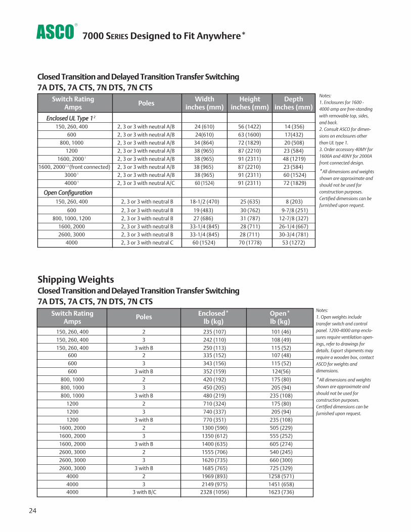
7000 SERIES Designed to Fit Anywhere*
Notes:1. Enclosures for 1600 -4000 amp are free-standingwith removable top, sides,and back.2. Consult ASCO for dimen-sions on enclosures otherthan UL type 1.3. Order accessory 40MY for1600A and 40NY for 2000Afront connected design.
Closed Transition and Delayed Transition Transfer Switching7A DTS, 7A CTS, 7N DTS, 7N CTS
Shipping Weights
Notes:1. Open weights includetransfer switch and controlpanel. 1200-4000 amp enclo-sures require ventilation open-ings, refer to drawings fordetails. Export shipments mayrequire a wooden box, contactASCO for weights anddimensions.
24
Depthinches (mm)
Heightinches (mm)
Widthinches (mm)
PolesSwitch Rating
Amps
Enclosed UL Type 1 2
150, 260, 400 2, 3 or 3 with neutral A/B 24 (610) 56 (1422) 14 (356)
600 2, 3 or 3 with neutral A/B 24(610) 63 (1600) 17(432)
800, 1000 2, 3 or 3 with neutral A/B 34 (864) 72 (1829) 20 (508)
1200 2, 3 or 3 with neutral A/B 38 (965) 87 (2210) 23 (584)
1600, 2000 1 2, 3 or 3 with neutral A/B 38 (965) 91 (2311) 48 (1219)
1600, 20001,3 (front connected) 2, 3 or 3 with neutral A/B 38 (965) 87 (2210) 23 (584)
3000 1 2, 3 or 3 with neutral A/B 38 (965) 91 (2311) 60 (1524)
4000 1 2, 3 or 3 with neutral A/C 60 (1524) 91 (2311) 72 (1829)
Open Configuration150, 260, 400 2, 3 or 3 with neutral B 18-1/2 (470) 25 (635) 8 (203)
600 2, 3 or 3 with neutral B 19 (483) 30 (762) 9-7/8 (251)
800, 1000, 1200 2, 3 or 3 with neutral B 27 (686) 31 (787) 12-7/8 (327)
1600, 2000 2, 3 or 3 with neutral B 33-1/4 (845) 28 (711) 26-1/4 (667)
2600, 3000 2, 3 or 3 with neutral B 33-1/4 (845) 28 (711) 30-3/4 (781)
4000 2, 3 or 3 with neutral C 60 (1524) 70 (1778) 53 (1272)
Open*lb (kg)
Enclosed*lb (kg)
PolesSwitch RatingAmps
150, 260, 400 2 235 (107) 101 (46)
150, 260, 400 3 242 (110) 108 (49)
150, 260, 400 3 with B 250 (113) 115 (52)600 2 335 (152) 107 (48)
600 3 343 (156) 115 (52)
600 3 with B 352 (159) 124(56)
800, 1000 2 420 (192) 175 (80)
800, 1000 3 450 (205) 205 (94)
800, 1000 3 with B 480 (219) 235 (108)
1200 2 710 (324) 175 (80)
1200 3 740 (337) 205 (94)
1200 3 with B 770 (351) 235 (108)
1600, 2000 2 1300 (590) 505 (229)
1600, 2000 3 1350 (612) 555 (252)
1600, 2000 3 with B 1400 (635) 605 (274)
2600, 3000 2 1555 (706) 540 (245)
2600, 3000 3 1620 (735) 660 (300)
2600, 3000 3 with B 1685 (765) 725 (329)
4000 2 1969 (893) 1258 (571)
4000 3 2149 (975) 1451 (658)4000 3 with B/C 2328 (1056) 1623 (736)
Closed Transition and Delayed Transition Transfer Switching7A DTS, 7A CTS, 7N DTS, 7N CTS
*All dimensions and weightsshown are approximate andshould not be used forconstruction purposes.Certified dimensions can befurnished upon request.
*All dimensions and weightsshown are approximate andshould not be used forconstruction purposes.Certified dimensions can befurnished upon request.
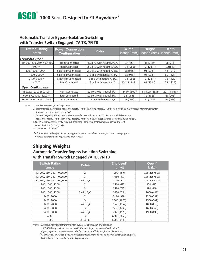
7000 SERIES Designed to Fit Anywhere*
Automatic Transfer Bypass-Isolation Switching with Transfer Switch Engaged 7A TB, 7N TB
Notes: 1. Handles extend 6-1/4 inches (159mm). 2. Recommended clearance to enclosure: 3 feet (914mm) from rear, 4 feet (1219mm) from front (25 inches required for transfer switch
drawout). Side or rear access required.3. For 4000 amp size, ATS and bypass sections can be reversed, contact ASCO. Recommended clearance to
enclosure: 3 feet (914mm) from rear, 5 feet (1524mm) from front (3 feet required for transfer switch rollout). 4. Specify optional accessory 40JY for 800 amp front - connected arrangement. All service and load
cables limited to top entry only.5. Contact ASCO for details.
Depthinches (mm)
Heightinches (mm)
Widthinches (mm)Poles
Switch Ratingamps
Enclosed UL Type 1150, 200, 230, 260, 4001, 600 Front Connected 2, 3 or 3 with neutral A/B/C 34 (864) 85 (2159) 28 (711)
800 1, 4 Front Connected 2, 3 or 3 with neutral A/B/C 38 (965) 91 (2311) 32 (813)
800, 1000, 12001, 2 Side/Rear Connected 2, 3 or 3 with neutral A/B/C 38 (965) 91 (2311) 48 (1219)
1600, 20001,2 Side/Rear Connected 2, 3 or 3 with neutral A/B/C 38 (965) 91 (2311) 60 (1524)
2600, 30001, 2 Side/Rear Connected 3 or 3 with neutral A/B/C 38 (965) 91 (2311) 72 (1829)
40003 Rear Connected 3 or 3 with neutral A/C 96-1/2 (2451) 91 (2311) 72 (1829)
150, 200, 230, 260, 4001 Front Connected 2, 3 or 3 with neutral B/C 19-3/4 (500)5 61-1/2 (1553)5 22-1/4 (565)5
600, 800, 1000, 12001, 2 Rear Connected 2, 3 or 3 with neutral B/C 38 (965) 72 (1829) 38 (965)
1600, 2000, 2600, 30001, 2 Rear Connected 2, 3 or 3 with neutral B/C 38 (965) 72 (1829) 38 (965)
Automatic Transfer Bypass-Isolation Switching with Transfer Switch Engaged 7A TB, 7N TB
Open*lb (kg)
Enclosed*lb (kg)
PolesSwitch Ratingamps
150, 200, 230, 260, 400, 600 2 990 (450) Contact ASCO
150, 200, 230, 260, 400, 600 3 1050 (477) Contact ASCO
150, 200, 230, 260, 400, 600 3 with B/C 1110 (505) Contact ASCO
800, 1000, 1200 2 1510 (685) 920 (417)
800, 1000, 1200 3 1580 (717) 990 (449)
800, 1000, 1200 3 with B/C 1650 (748) 1060 (481)
1600, 2000 2 2180 (989) 1300 (589)
1600, 2000 3 2360 (1070) 1550 (702)
1600, 2000 3 with B/C 2540 (1152) 1800 (815)
2600, 3000 3 2730 (1240) 1690 (768)
2600, 3000 3 with B/C 3360 (1525) 1980 (899)
4000 3 6300 (2858) –
4000 3 with C 6900 (3130) –
Shipping Weights
Notes: 1.Open weights include transfer switch, bypass-isolation switch and controller.1600-4000 amp enclosures require ventilation openings, refer to drawings for details. Export shipments may require a wooden box, contact ASCO for weights and dimensions.
Open Configuration
25
Power ConnectionConfiguration
*All dimensions and weights shown are approximate and should not be used for construction purposes. Certified dimensions can be furnished upon request.
*All dimensions and weights shown are approximate and should not be used for construction purposes. Certified dimensions can be furnished upon request.
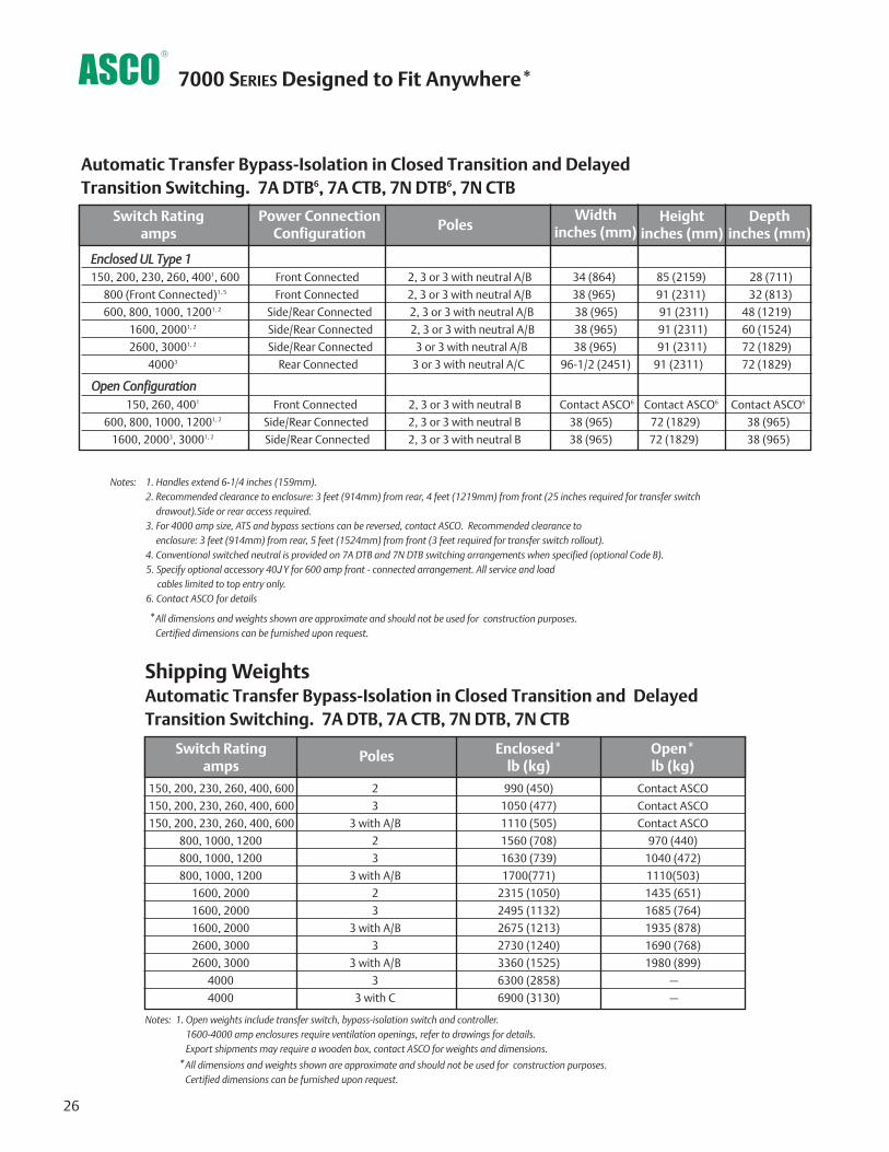
Automatic Transfer Bypass-Isolation in Closed Transition and DelayedTransition Switching. 7A DTB6, 7A CTB, 7N DTB6, 7N CTB
Notes: 1. Handles extend 6-1/4 inches (159mm). 2. Recommended clearance to enclosure: 3 feet (914mm) from rear, 4 feet (1219mm) from front (25 inches required for transfer switch
drawout).Side or rear access required.3. For 4000 amp size, ATS and bypass sections can be reversed, contact ASCO. Recommended clearance to
enclosure: 3 feet (914mm) from rear, 5 feet (1524mm) from front (3 feet required for transfer switch rollout).4. Conventional switched neutral is provided on 7A DTB and 7N DTB switching arrangements when specified (optional Code B).5. Specify optional accessory 40JY for 600 amp front - connected arrangement. All service and load
cables limited to top entry only.6. Contact ASCO for details
Depthinches (mm)
Heightinches (mm)
Widthinches (mm)Poles
Switch Ratingamps
Enclosed UL Type 1150, 200, 230, 260, 4001, 600 Front Connected 2, 3 or 3 with neutral A/B 34 (864) 85 (2159) 28 (711)
800 (Front Connected)1, 5 Front Connected 2, 3 or 3 with neutral A/B 38 (965) 91 (2311) 32 (813)
600, 800, 1000, 12001, 2 Side/Rear Connected 2, 3 or 3 with neutral A/B 38 (965) 91 (2311) 48 (1219)
1600, 20001, 2 Side/Rear Connected 2, 3 or 3 with neutral A/B 38 (965) 91 (2311) 60 (1524)
2600, 30001, 2 Side/Rear Connected 3 or 3 with neutral A/B 38 (965) 91 (2311) 72 (1829)
40003 Rear Connected 3 or 3 with neutral A/C 96-1/2 (2451) 91 (2311) 72 (1829)
150, 260, 4001 Front Connected 2, 3 or 3 with neutral B Contact ASCO6 Contact ASCO6 Contact ASCO6
600, 800, 1000, 12001, 2 Side/Rear Connected 2, 3 or 3 with neutral B 38 (965) 72 (1829) 38 (965)
1600, 20003, 30001, 2 Side/Rear Connected 2, 3 or 3 with neutral B 38 (965) 72 (1829) 38 (965)
Automatic Transfer Bypass-Isolation in Closed Transition and DelayedTransition Switching. 7A DTB, 7A CTB, 7N DTB, 7N CTB
Open*lb (kg)
Enclosed*lb (kg)
PolesSwitch Ratingamps
150, 200, 230, 260, 400, 600 2 990 (450) Contact ASCO
150, 200, 230, 260, 400, 600 3 1050 (477) Contact ASCO
150, 200, 230, 260, 400, 600 3 with A/B 1110 (505) Contact ASCO
800, 1000, 1200 2 1560 (708) 970 (440)
800, 1000, 1200 3 1630 (739) 1040 (472)
800, 1000, 1200 3 with A/B 1700(771) 1110(503)
1600, 2000 2 2315 (1050) 1435 (651)
1600, 2000 3 2495 (1132) 1685 (764)
1600, 2000 3 with A/B 2675 (1213) 1935 (878)
2600, 3000 3 2730 (1240) 1690 (768)
2600, 3000 3 with A/B 3360 (1525) 1980 (899)
4000 3 6300 (2858) –
4000 3 with C 6900 (3130) –
Shipping Weights
Notes: 1. Open weights include transfer switch, bypass-isolation switch and controller.1600-4000 amp enclosures require ventilation openings, refer to drawings for details.Export shipments may require a wooden box, contact ASCO for weights and dimensions.
Open Configuration
7000 SERIES Designed to Fit Anywhere*
26
Power ConnectionConfiguration
*All dimensions and weights shown are approximate and should not be used for construction purposes. Certified dimensions can be furnished upon request.
*All dimensions and weights shown are approximate and should not be used for construction purposes. Certified dimensions can be furnished upon request.

27
48.00CableCompartment
Emergency LugsPoles 1 and 4
Emergency LugsPoles 2 and 3
Load Lugs MountedPointing UpwardFor Top CableEntry, Lug Plates MayBe Turned To Point Downward ForBottom Cable Entry
Normal LugsPoles 2 and 4
Normal LugsPoles 1 and 3
Bypass Handle
Isolation Handle
59.05Ref 12.42
Ref
TransferSwitch
Drawn Out(Isolated)Position
Transfer SwitchCompartment
Controls &Indication
Group 5Controller UserInterface
Field WiringTerminal Block(TB)
Additional Controls ifRequired
BypassSwitch
Manual OperationHandle
IsolationHandle
17.00
38.76
91.00
35.24
Front View (Covers Installed) Right Side View (Covers Removed)
17.00
38.76
35.24
91.00
Transfer SwitchCompartment
Controls andIndication
Group 5Controller UserInterface
Field WiringTerminal Block(TB)
Front View (Doors and Top Covers Installed)
7000 SERIES Designed to Fit Anywhere*
Standard and Optional Power Connection Configurations for 800 Amp, Automatic Transfer Bypass Isolation Switches 7ATB, 7NTB, 7ADTB, 7ACTB, 7NDTB, 7NCTB
Bypass Handle
IsolationHandle
59.05REF
39.00CG
12.42 REF
32.00
CableCompartment
Ground Bus
Load Lugs
Normal Lugs
Emergency Lugs
Right Side View(Covers Removed)
800 Amp Optional Front Connected Design- 32 Inch Depth
BypassSwitch
Manual OperationHandle
Standard Rear Connected Design
IsolationHandle
*All dimensions and weightsshown are approximate andshould not be used for con-struction purposes. Certifieddimensions can be furnishedupon request.
Emerson Network Power. The world leader in business-critical continuity. EmersonNetworkPower.com
AC Power Systems
Connectivity
DC Power Systems
Embedded Power
Integrated Cabinet Solutions
Outside Plant
Precision Cooling
Services
Emerson Network Power and the Emerson Network Power logo are trademarks and service marks of Emerson Electric Co. ©2008 Emerson Electric Co.
Publication 3040 R11 © November, 2008 Printed in the U.S.A.
Power Switching & Controls Site Monitoring
Surge & Signal Protection
A SCO Power Technologies50 Hanover Road F l o r ha m Par k , N J 0 7 9 3 2USA
8 0 0 8 0 0 A SCOW W W.A S COP OWE R. COM
A SIA
AUS T R A L I A
B R A Z I L
C AN ADA
GERMANY
J A PA N
M E X I CO
SOU TH AFRIC A
SOU TH AMERIC A
U N I T E D A R A B E M I R AT E S
U N I T E D K I N G D O M
U N I T E D S TATE S


