18
Rev. 2, 9/22/10 PowerAire ™ Installation Guide

Rev. 2, 9/22/10
PowerAire™ Installation Guide
Introduction
Tate’s PowerAireTM
Variable Speed Fan Assist device provides the user with unparallel local control of
airflow to precisely meet individual rack cooling demands in areas of low or no static pressure without
user intervention. Automatic control based on user a defined set point guarantees that each piece of IT
hardware installed in the users rack is supplied with sufficient air volume at all times.
Method of Operation
Tate’s PowerAireTM
product is designed to work in conjunction with the DirectAireTM
Directional Grate,
the to meet high airflow requirements and accurate air flow deliver to the rack face. The PowerAireTM
is
designed to alleviate airflow issues in areas where little to no static pressure exists due to underfloor
restrictions, or insufficient floor heights. The PowerAireTM
is designed to function on most finished floor
heights greater than 12”. Since IT loads are rarely stable on a rack to rack basis, the PowerAireTM
is
designed to throttle the amount of air delivered to an individual rack based on its current inlet air
temperatures. This guarantees sufficient air delivery to the rack, as hot air recirculation would occur in
insufficient airflow delivery situations. This balancing act is managed by a high speed PID controller
which monitors each temperature sensor in a multiloop temperature evaluation mode. Each of the four
sensors installed at the rack face are polled for current temperature value, and then compared to each
other. The probe having the highest value is then used as the control point. This control point is then
used to determine the correct speed for the variable speed fan. The command signal is sent to the fan
controller, which then changes the fan speed producing more or less air to pass through the DirectAireTM
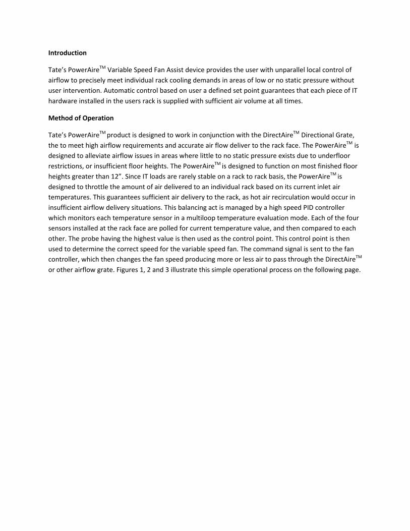
or other airflow grate. Figures 1, 2 and 3 illustrate this simple operational process on the following page.
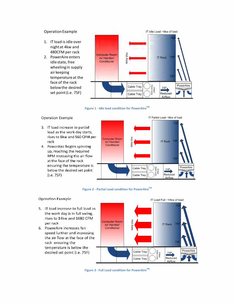
Figure 1
Figure 2
Figure 3
Operation Example
1. IT load is idle over
night at 4kw and
480CFM per rack
2. PowerAire enters
idle state, free
wheeling in supply
air keeping
temperature at the
face of the rack
below the desired
set point (i.e. 75F)
Figure 1 - Idle load condition for PowerAireTM
Figure 2 - Partial Load condition for PowerAireTM
Figure 3 - Full Load condition for PowerAireTM
Installation Instructions
1. Remove the PowerAireTM
unit from the factory packaging. Take care to check that each
required separate component is in the shipping packaging as listed below, and figure 4 for
details.
A. 1 x PowerAireTM
Fan Assist Device
B. 1 x Four Point Color Coded Temperature Sensor Tree
C. 10 x Temperature Sensor Tree Zip Ties
D. 4 x Tool Less Roll Formed Stringer Hangers
E. 1 x PowerAireTM
power cord
F. The PowerAireTM
is designed for optimum use with Tate’s DirectAireTM
airflow panel
ordered separately; other airflow panels may reduce the performance of the
PowerAireTM
.
Figure 4 - Illustrated Parts List
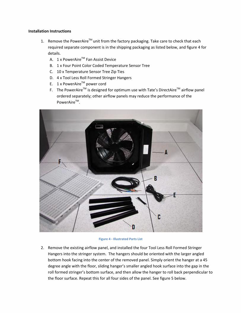
2. Remove the existing airflow panel, and installed the four Tool Less Roll Formed Stringer
Hangers into the stringer system. The hangers should be oriented with the larger angled
bottom hook facing into the center of the removed panel. Simply orient the hanger at a 45
degree angle with the floor, sliding hanger’s smaller angled hook surface into the gap in the
roll formed stringer’s bottom surface, and then allow the hanger to roll back perpendicular to
the floor surface. Repeat this for all four sides of the panel. See figure 5 below.

3.
Figure 5 –Position hanger parallel to the floor with short angled edge aligned to opening in roll form stringer

Figure 6 - Insert hanger into roll form opening and catch the top angle inside the stringer
Figure 7 - Release hanger and allow it to return perpendicular to the floor

Each PowerAireTM
unit must be powered from the appropriate outlet. For 120V and 240V
installations, a C14 power inlet is provided on the unit. The supply voltage of the unit will dictate
the power cord supplied with the unit, which will be 6’ feet in length, a list of the required
power outlet is shown below in table 1. If the supplied cord does not meet the site
requirements, a use supplied cord set may be used if it meets the voltage and amperage
requirements of the power module. Figure 8 shows an example of a power feed to the unit.
Table 1 - Power Feed Requirements for Unit
PowerAireTM
Power Feed
Requirements
Voltage Outlet Required
120V NEMA 5-15R
240V NEMA L6-15R
277V NEMA L7-15R
Figure 8 – Power Outlet from Site Source
4. Pickup the PowerAireTM
unit using the inside lip around the inside perimeter of the
PowerAireTM
unit. Be sure to orient the units extended shroud below the rack. Lower the
PowerAireTM
unit at the edge that extends beyond the perimeter of the unit first so that this
edge will be oriented beneath the rack see figure 9 and 10 below. Lock the lip of the unit into

the hanger, the lower the opposite side into the waiting Tool Less hanger. Once this side is
also resting in the hanger support, manipulated the unit so that each hanger on the alternate
sides are also secure the unit into place.
Figure 9 - PowerAireTM
Unit Installed on hangers in correct orientation
Figure 10 - Installation of Fan Unit onto Tool Less Hangers
5. Plug in the temperature sensor tree into the labeled connection port on the left side of the
unit when facing the rack. Route the temperature probes into the rack. This can typically be
done by routing the probes through the cable entry hole serving the rack, or by drilling a new
0.5” hole at the front of the rack, through the panel directly below the rack. If a new hole is
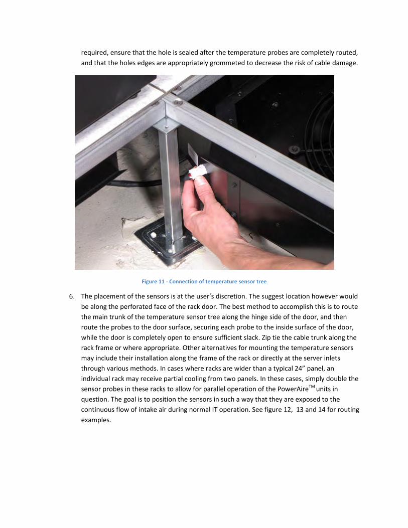
required, ensure that the hole is sealed after the temperature probes are completely routed,
and that the holes edges are appropriately grommeted to decrease the risk of cable damage.
Figure 11 - Connection of temperature sensor tree
6. The placement of the sensors is at the user’s discretion. The suggest location however would
be along the perforated face of the rack door. The best method to accomplish this is to route
the main trunk of the temperature sensor tree along the hinge side of the door, and then
route the probes to the door surface, securing each probe to the inside surface of the door,
while the door is completely open to ensure sufficient slack. Zip tie the cable trunk along the
rack frame or where appropriate. Other alternatives for mounting the temperature sensors
may include their installation along the frame of the rack or directly at the server inlets
through various methods. In cases where racks are wider than a typical 24” panel, an
individual rack may receive partial cooling from two panels. In these cases, simply double the
sensor probes in these racks to allow for parallel operation of the PowerAireTM
units in
question. The goal is to position the sensors in such a way that they are exposed to the
continuous flow of intake air during normal IT operation. See figure 12, 13 and 14 for routing
examples.

Figure 12 - Routing temperature sensor tree through cable entry point
Figure 13 - Temperature Sensor installation

Figure 14 - Securing Sensor Tree to Rack with Sufficient Slack for Door Operation
7. The unit can now be powered on by plugging it into (figure 15) the appropriate power outlet
outline in table 1. Once power is applied, and the power switch is turn on, (figure 16) the unit
will begin the startup procedure. This process is completed when the user display shows the
current peak temperature. Figure 13 shows this connection method.

Figure 15 - Plugging the power cord into the unit
Figure 16 – Location of Power Switch
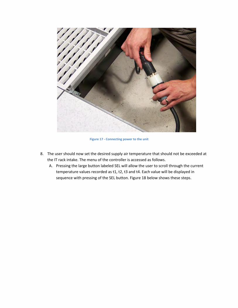
Figure 17 - Connecting power to the unit
8. The user should now set the desired supply air temperature that should not be exceeded at
the IT rack intake. The menu of the controller is accessed as follows.
A. Pressing the large button labeled SEL will allow the user to scroll through the current
temperature values recorded as t1, t2, t3 and t4. Each value will be displayed in
sequence with pressing of the SEL button. Figure 18 below shows these steps.

Figure 18 - Scrolling Through Temperature Values
B. After the temperature values are displayed, pressing SEL again will show the current set
point value indicated by SP. (Figure 15)
C. Pressing the SEL button again will light the PRG buttons, and allow the user to adjust the
set point as desired. Pressing either button once will adjust the set point 0.1F, holding
the button for approximately 1 seconds will quickly adjust the set point in 1.0F
increments.
D. Pressing the SEL button again after the desired SP is entered will store the value and
then display the current command percent opening the controller has sent to the
actuator. The actuator will adjust to this value in time as the damper follows the
command position.
E. Pressing the SEL button again will return the user to main screen which displays the
current peak temperature value recorded from the temperature sensor tree. Figure 19
shows this procedure.

Figure 19 - Programming Set point for PowerAire Control
9. Once the value has been set, and all programming completed. Reinstall the DirectAireTM
or
other panel above the PowerAireTM
unit and proceed to the next unit. It is best to work right
to left due to the connector layout on the PowerAireTM
unit. Each subsequent unit can fully
access connector points on its neighboring unit, allowing for easier access to power
connections for daisy chaining up to 4 units together.

Figure 20 - Installation of DirectAire Panel
10. The PowerAireTM
will now run automatically, increasing and decreasing fan speed as the
temperature values change based on changing IT equipment conditions. The unit is meant to
function as a hot spot reduction device, pulling air into areas with little or no static pressure
due to underfloor restrictions, and insufficient floor heights. Best practices dictate that
underfloor plenum spaces should have all unnecessary restrictions removed from beneath
the floor, but often site conditions make this difficult or not cost effective.
Figure 21 - Typical Operation
11. The PowerAireTM
units are completely maintenance free. The temperature display will
continue to show the current peak temperature during normal operation. Power failure, or
control failure will result in a 0% fan speed although air may still flow from the panel due to
the effect of underfloor air pressure alone. After a power interruption event, the PowerAire TM
unit will reenter the last operation condition when power is restored.
12. The PowerAireTM
unit can affected the air flow that is delivered to other nearby panels if
insufficient air delivery is widespread in the data center environment. The installer should
verify after installation that sufficient air volume is reaching IT hardware in the vicinity of the
PowerAireTM
installation location. Failure to do this may result in a reduction of airflow in
neighboring panels, and should be avoided.
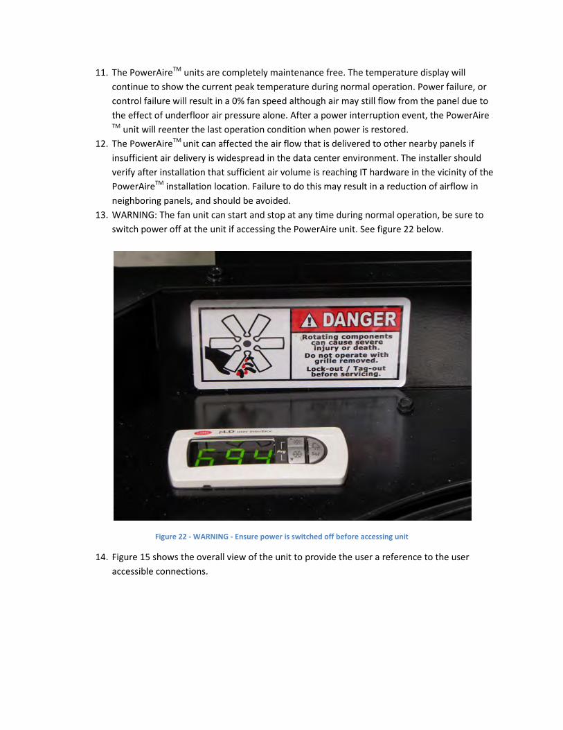
13. WARNING: The fan unit can start and stop at any time during normal operation, be sure to
switch power off at the unit if accessing the PowerAire unit. See figure 22 below.
Figure 22 - WARNING - Ensure power is switched off before accessing unit
14. Figure 15 shows the overall view of the unit to provide the user a reference to the user
accessible connections.

A. Temperature Sensor Port
B. Power inlet location


