71
Technical Information and Installation Manual Output range 43 to 531 kWe 4212933/06 - 04/19 Subject to modifications PowerBloc EG Combined Heat and Power

Technical Information and Installation ManualOutput range 43 to 531 kWe4212933/06 - 04/19 Subject to modifications
PowerBloc EG Combined Heat and Power

2 4212933/06 - 04/19
PowerBloc EG 43 - 531 kWe
1. An Introduction to Hoval Combined Heat and Power1.1. Foreword................................................................................................................................... 51.2. Introduction.............................................................................................................................. 5
2. Safety Information2.1. Safety Information Introduction............................................................................................. 6 2.2. SpecificWarnings....................................................................................................................6
3. ImportantNotes3.1. Acceptance of Delivery............................................................................................................ 83.2. Scope of Guarantee................................................................................................................. 83.3. InstructionManuals.................................................................................................................83.4. Standards.................................................................................................................................8
4. Technical Data4.1. PowerBloc EG (43-104) Technical Data................................................................................. 94.2. PowerBloc EG (130-260) Technical Data............................................................................... 10 4.3. PowerBloc EG (320-355/NOx) Technical Data....................................................................... 114.4. PowerBloc EG (460-530/NOx) Technical Data....................................................................... 124.5. PowerBloc EG (43-530/NOx) Cooler Technical Data............................................................. 134.6. PowerBlocEG(43-50)Dimensions........................................................................................144.7. PowerBlocEG(70)Dimensions.............................................................................................154.8. PowerBlocEG(104)Dimensions...........................................................................................164.9. PowerBlocEG(130)Dimensions............................................................................................174.10. PowerBlocEG(210,210NOx)Dimensions...........................................................................184.11. PowerBlocEG(260-530/NOx)Dimensions............................................................................194.12. DimensionsforEmergencycoolers(EG43-130)...................................................................204.13. DimensionsforEmergencycoolers(EG210-530).................................................................214.14. DimensionsforMixturecoolers(EG104-530/NOx)...............................................................224.15. Dimensionsforsecondarysilencers(EG43-530).................................................................23
5. InstallationRequirements5.1. SiteRequirements...................................................................................................................245.2. AdditionalNotesfortheInstaller............................................................................................245.3. ReadinessforOperation.........................................................................................................255.4. Further Important Information................................................................................................ 255.5. WasteDisposal.........................................................................................................................25
6. WaterQuality6.1. HeatingWater...........................................................................................................................26
7. TypicalPipeworkSchematics7.1. CHP in Parallel......................................................................................................................... 277.2. CHPinSeries...........................................................................................................................27
8. Construction8.1. ConstructionofTheCHPPlant...............................................................................................288.2. TheGasEngine........................................................................................................................288.3. The Generator.......................................................................................................................... 288.4. EngineCoolingWaterHeatExchanger..................................................................................298.5. ExhaustGasHeatExchanger.................................................................................................298.6. EngineCoolingCircuit............................................................................................................298.7. HeatingWaterCircuit..............................................................................................................298.8. ExhaustCatalyticConverter...................................................................................................298.9. Ventilation................................................................................................................................. 298.10. Monitoringdevices................................................................................................................. 29
9. FunctionalDescription9.1. FunctionalDescriptionofCHPPlant.....................................................................................30
Contents
34212933/06 - 04/19
PowerBloc EG 43 - 531 kWe
10. Control Panel - Overview 10.1. Control Panel............................................................................................................................3110.2. Overview of Functionality....................................................................................................... 3210.3. ManualandAutomaticOperation..........................................................................................3210.4. SafetySystem..........................................................................................................................3310.5. GridMonitoring........................................................................................................................3310.6. GeneratorMonitoring..............................................................................................................3310.7. EngineControl.........................................................................................................................3310.8. Speed Control.......................................................................................................................... 3310.9. Power Output Control.............................................................................................................. 3310.10. Lambda Control....................................................................................................................... 3310.11. TouchScreenDisplay..............................................................................................................33
11.ControlsOverview................................................................................................................................34
12. Pre-Commisioning12.1. Engine......................................................................................................................................4112.2. Oil Supply................................................................................................................................. 4112.3. GasSupply...............................................................................................................................4112.4. HeatingWaterSystem.............................................................................................................4112.5. Electrical Connection.............................................................................................................. 4112.6. Static maintenance.................................................................................................................. 4112.7 Pre-CommissioningChecklist................................................................................................42
13. MaintenanceAndServicing13.1. Overview................................................................................................................................... 4513.2. OilChange................................................................................................................................4513.3. OilChangeProcedure.............................................................................................................4513.4. SparkPlugs..............................................................................................................................4513.5. Air Filter.................................................................................................................................... 4513.6. Valve Clearance....................................................................................................................... 4613.7. Starter Battery.......................................................................................................................... 4613.8. EngineCoolantPressure........................................................................................................4613.9. Generator.................................................................................................................................. 4613.10. Postservice..............................................................................................................................4613.11. Day-to-day operation............................................................................................................... 4613.12. Maximumwearvalues.............................................................................................................4613.13. ServiceIntervalsandScopeofWork.....................................................................................4713.14-27. MaintenanceSchedules(EG43-EG530/NOx).........................................................................48
14. CustomerService14.1. ContactingHoval.....................................................................................................................6214.2. RemoteServicing....................................................................................................................63
15. FaultFinding15.1. Alarms......................................................................................................................................6315.2. FaultCodes............................................................................................................................. 6415.3. GasLeaks................................................................................................................................ 6615.4. OilLeaks.................................................................................................................................. 6615.5. HeatingCircuitLeaks............................................................................................................. 6615.6. ExhaustGasLeaks..................................................................................................................66

4 4212933/06 - 04/19
PowerBloc EG 43 - 531 kWe
16 Accessories16.1. Flexibleconnections...............................................................................................................6716.2. Extendedexhaustgaspurification........................................................................................6716.3. Interface.................................................................................................................................... 6816.4. Ventilation Controller recirculation and room air................................................................. 6816.5. Electricity meter with convertor............................................................................................. 6816.6. LowfrequencysilencertypeS...............................................................................................6816.7. LowfrequencysilencertypeG..............................................................................................6816.8. Networkandsystemprotection.............................................................................................6816.9. Emergencycooling.................................................................................................................6916.10 Emergencypowerfunctionmanual......................................................................................6916.11 Stainlesssteelcondensationtrap.........................................................................................6916.12 Gasdetectionsystem.............................................................................................................6916.13 Smokewarningsystem..........................................................................................................6916.14 Oil/waterwarningdevice........................................................................................................7016.15 Warninghornandlight...........................................................................................................7016.16 CondensateboxKB22............................................................................................................7016.17 NeutralisationboxKB23.........................................................................................................7016.18 NeutralisationboxKB24.........................................................................................................7016.19 Neutralisationgranulate.........................................................................................................70
54212933/06 - 04/19
PowerBloc EG 43 - 531 kWe
1.1. Foreword
These instructions have been written to give a brief description of the PowerBloc EG (43-530) combined heat and power plant (CHP plant), their installation, commissioning, operation and subsequent preventative maintenance.
The installation of CHP plant and their ancillary equipment is normally carried out by a competent Engineer, and for the purpose of this manual they are regarded as the installer, and, as such, it is their responsibility to ensure that they have read and understood the contents of this manual before installing and operating the CHP plant. As the manufacturer, Hoval cannot accept any responsibility for any damage, faults or injuries caused by non compliance with this published document.
A copy of this manual must be available on site at all times as the operating personnel will need to be able to reference it as quickly as possible. It is imperative that this manual has been read and understood before operating the CHP plant.
Hoval, or Hoval approved Engineers will commission the CHP plant. It is essential that the installer and the operator of the CHP plant are present at the commissioning handover as they can then be instructed on the day-to-day use and operation of the CHP plant. If this is not possible, or additional training is required, a further site visit can be arranged through Hoval. Day-to-day checks of the CHP must be completed by the operator.
Hoval retains the copyright to this documentation. The drawings, images or information may not be reproduced or distributed, in their entirety or as extracts, or passed to others, without written consent of Hoval Ltd.
1.2. Introduction
A Hoval combined heat and power plant consists of a gas fuelled internal combustion engine coupled to a three-phase synchronous generator. With the CHP plant it is designed that both the electricity and heat generated are utilised resulting in high efficiencies, much more efficient than a typical fossil fuel power sta-tion.
Hoval CHP plant is generally supplied skid mounted and housed within a sound reduction casing for installation into a suitable building plant room. Alternatively the CHP plant can be supplied within a complete packaged plant room for external siting.
The CHP plant has highly sophisticated controls as it is responsible for the fully automatic operation of the plant. In addition to controlling the engine and monitoring all of its values, the controls are also responsible for the synchronisation of the generator to the grid and the dissipation of heat from the engine to the connected heating circuit. The emissions from the exhaust system are measured and tightly controlled to their set values complete with low NOx from the assistance of the catalyctic converters. If necessary the Hoval CHP plant can be equipped to be back-up power generation should the electrical power from the mains fail. Should this be required, Hoval Technical should be contacted for assistance.
The CHP is as standard delivered in a sound reduction housing but can be supplied in a containerised plant-room. Additional silencers are available for the exhaust system to meet the most stringent requirements.
The controls installed on the CHP plant can be interrogated by the touch-screen interface. Many different ex-ternal interfaces can be configured, however these need to be confirmed at time of order as they may result in hardware changes. These interfaces can be either read from a master controls system or over other me-dia such as the internet. Remote control such as the internet interface can be used to quickly rectify faults caused by changing operating conditions.
All Hoval CHP's are built with select, quality components. All models contain MAN natural gas engines and Marelli or Stamford synchronous generators, and controlled with suitably certified equipment.
1. An Introduction to Hoval Combined Heat and Power
6 4212933/06 - 04/19
PowerBloc EG 43 - 531 kWe
2.1. Safety Information Introduction
The CHP plant is manufactured to a very high level to ensure that it complies with all safety requirements and regulations. However, due to the nature of the equipment dangers are present and these may pose a risk if it is operated improperly or by untrained personnel.
The operator on site is responsible to ensure that only trained and authorised personnel can enter, operate and maintain the CHP plant. IFINDOUBT,CONTACTHOVALFORADVICE.
Safety must never be compromised when operating or maintaining the CHP plant.
The operator on site should inspect the plant on a daily basis for any signs of damage or defects and report them immediately.
Any unauthorised modifications are prohibited as this may affect safety and correct functionality of the plant.
Before work commences for example on a preventative maintenance or break-down visit the controls must be locked off against an inadvertent start-up.
Apermit-to-worksystemshouldbeputinplacebytheoperatorpriortoallsuchworkbeing undertaken.
The exhaust system must be sealed, insulated and not have any leaks. If a gas escape is detected the CHP plant must be switched off immediately and an appropriate specialist investigate the issue. Drain points must be fitted where required.
Used oil and coolant must be disposed of in accordance to the local regulations.
2.2. SpecificWarnings
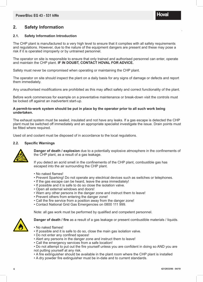
Dangerofdeath/explosion due to a potentially explosive atmosphere in the confinements of the CHP plant, as a result of a gas leakage.
If you detect an acrid smell in the confinements of the CHP plant, combustible gas has escaped into the air surrounding the CHP plant. • No naked flames!• Prevent Sparking! Do not operate any electrical devices such as switches or telephones.• If the gas escape can be heard, leave the area immediately!• If possible and it is safe to do so close the isolation valve. • Open all external windows and doors!• Warn any other persons in the danger zone and instruct them to leave!• Prevent others from entering the danger zone!• Call the fire service from a position away from the danger zone!• Contact National Grid Gas Emergencies on 0800 111 999.
Note: all gas work must be performed by qualified and competent personnel.
Dangerofdeath/fire as a result of a gas leakage or present combustible materials / liquids. • No naked flames!• If possible and it is safe to do so, close the main gas isolation valve.• Do not enter any confined spaces!• Alert any persons in the danger zone and instruct them to leave!• Call the emergency services from a safe location!• Do not attempt to put out the fire yourself unless you are confident in doing so AND you are not putting yourself at any risk. • A fire extinguisher should be available in the plant room where the CHP plant is installed• A dry powder fire extinguisher must be in-date and to current standards.
2. Safety Information
74212933/06 - 04/19
PowerBloc EG 43 - 531 kWe
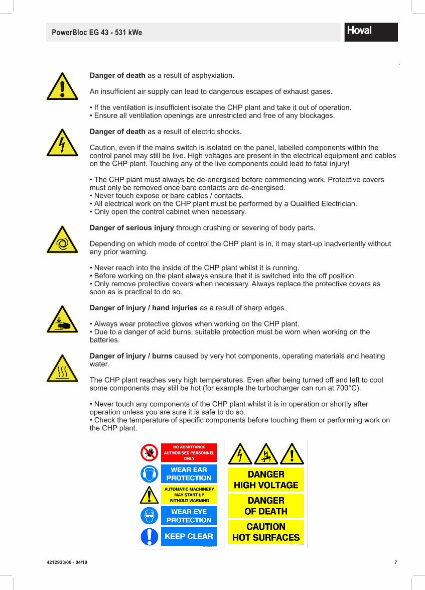
Dangerofdeath as a result of asphyxiation.
An insufficient air supply can lead to dangerous escapes of exhaust gases.
• If the ventilation is insufficient isolate the CHP plant and take it out of operation.• Ensure all ventilation openings are unrestricted and free of any blockages.
Dangerofdeath as a result of electric shocks.
Caution, even if the mains switch is isolated on the panel, labelled components within the control panel may still be live. High voltages are present in the electrical equipment and cables on the CHP plant. Touching any of the live components could lead to fatal injury!
• The CHP plant must always be de-energised before commencing work. Protective covers must only be removed once bare contacts are de-energised. • Never touch expose or bare cables / contacts.• All electrical work on the CHP plant must be performed by a Qualified Electrician. • Only open the control cabinet when necessary.
Dangerofseriousinjury through crushing or severing of body parts.
Depending on which mode of control the CHP plant is in, it may start-up inadvertently without any prior warning.
• Never reach into the inside of the CHP plant whilst it is running.• Before working on the plant always ensure that it is switched into the off position. • Only remove protective covers when necessary. Always replace the protective covers as soon as is practical to do so.
Dangerofinjury/handinjuries as a result of sharp edges.
• Always wear protective gloves when working on the CHP plant.• Due to a danger of acid burns, suitable protection must be worn when working on the batteries.
Dangerofinjury/burns caused by very hot components, operating materials and heating water.
The CHP plant reaches very high temperatures. Even after being turned off and left to cool some components may still be hot (for example the turbocharger can run at 700°C).
• Never touch any components of the CHP plant whilst it is in operation or shortly after operation unless you are sure it is safe to do so. • Check the temperature of specific components before touching them or performing work on the CHP plant.
8 4212933/06 - 04/19
PowerBloc EG 43 - 531 kWe
3.1. Acceptance of Delivery
A visual inspection upon delivery should be performed including a check to ensure all components are present. In the event of there being damage or missing parts, the necessary steps should be followed as specified in the delivery contract.
The cost for correcting the damage shall be taken over by the individual risk bearer.
3.2. Scope of Guarantee
The guarantee does not cover defects caused by: - Non-observance of these instructions - Non-observance of the MAN engine instructions - Incorrect installation - Unauthorised modifications - Improper use - Improper maintenance including day-to-day checks - Contaminated operating media (gas, water, combustion air) - Unsuitable chemical additives in the water circuits - Damage due to excessive force - Corrosion due to halogen compounds - Corrosion due to nonconforming water quality - Corrosion due to unsuitable and/or damp storage conditions
3.3. InstructionManuals
As well as this document please refer to the specific MAN engine and Marelli / Stamford Generator manuals. A copy of all documentation should be kept with the CHP plant.Additional sources of information: - Hoval catalogue - Standards and regulations
3.4. Standards
When installing, operating and maintaining the CHP plant you must comply with all country-specific laws, standards and directives.
The installation must be in accordance with current I.E.E. Regulations, Engineering Networks Association G59/3 recommendations, relevant British & European standards and Codes of Practice, Building Regula-tions and Local Authority ByLaws.
3. ImportantNotes

94212933/06 - 04/19
PowerBloc EG 43 - 531 kWe
4. Technical Data4.1. Hoval PowerBloc EG (43-104) Type (43) (50) (70) (104)
Electrical power 4 kW 26-43 31-50 41-70 62-100Thermal output 4 kW 43-63 56-79 73-113 104-136Firing heat output kW 89-129 103-146 136-204 184-273Electrical efficiency (net) (full load 100 %) % 33.4 34.3 34.4 36.6
(partial load 80 %) % 31.2 33.0 32.9 35.3(partial load 60 %) % 29.4 30.2 30.2 33.8
Thermal efficiency (net) (full load 100 %) % 48.8 54.1 55.4 49.7(partial load 80 %) % 49.0 53.7 53.7 52.3(partial load 60 %) % 48.9 54.4 53.4 56.6
Total efficiency (net) (full load 100 %) % 82.2 88.4 89.7 86.3(partial load 80 %) % 80.2 86.7 86.6 87.6(partial load 60 %) % 78.3 84.6 83.6 90.4
Power to heat ratio at full load 0.68 0.63 0.62 0.74Flow temperature °C 90 90 90 90Minimum/maximum return temperature °C 50/70 50/70 50/70 50/70Volume flow heating m3/h 2.8 3.5 5.0 6.0Minimum/maximum operating pressure (psv 3 bar) 2 bar 1/2.5 1/2.5 1/2.5 1/2.5Hydraulic resistance mbar 50-60 50-60 50-60 50-60Minimum/maximum gas pressure mbar 18-100 18-100 18-100 18-100Gas consumption m3/h 12.9 14.6 20.4 27.3Exhaust gas temperature °C 120 120 120 120Maximum exhaust gas back pressure kPa 1.5 1.5 1.5 1.5Exhaust gas flow - moist kg/h 159 192 272 566Exhaust gas flow - dry m3/h 129 156 221 510Standard emission rate @ 5% O2 nitrogen oxide (NOx) mg/m3 <250 <250 <250 <500 carbon monoxide (CO) mg/m3 <300 <300 <300 <300Upgraded emission rate5 @ 5% O2 nitrogen oxide (NOx) mg/m3 <50 <50 <50 N/A carbon monoxide (CO) mg/m3 <100 <100 <100 N/ASupply air temperature °C 10-30 10-30 10-30 10-30Supply air flow m3/h 2639 3012 4451 4030Combustion air m3/h 150 181 257 511Residual pressure for supply/exhaust air system Pa approx. 100Maximum extract air temperature °C 50 50 50 50Extract air quantity m3/h 2517 2865 4241 3613Maximum radiant heat kW 12 17 23 13Dimensions see dimensional drawingSound emission at 1 m distance 1.3 dB(A) 62 62 68 70Exhaust gas sound emission at 10 m distance 3 dB(A) 65 65 70 70As above with low-frequency silencer (external) (type G) dB(A) 40 40 45 45Engine manufacturer MAN MAN MAN MANModel E0834 E312 E0834 E302 E0836 E302 E0836 LE302ISO-standard output kW 47 54 75 107Nominal speed of rotation rpm 1500 1500 1500 1500Fuel natural gas natural gas natural gas natural gasCylinder 4 4 6 6Displacement dm3 4.58 4.58 6.87 6.87Bore mm 108 108 108 108Stroke mm 125 125 125 125Average effective pressure bar 8.21 9.43 8.73 12.80Average piston speed m/s 6.3 6.3 6.3 6.25Compression ratio 13:1 13:1 13:1 11:1Lubricating oil consumption kg/h 0.040 0.040 0.060 0.075Lubricating oil volume min./max. dm3 17/25 17/25 24/34 24/34Generator manufacturer StamfordModel UCG224E2 UCG224F2 UCG274C2 UCG274E2Type synchronous synchronous synchronous synchronousType power rating kVA 51 62 85 119Speed of rotation rpm 1500 1500 1500 1500Efficiency % 93 94.7 92.8 93.7Voltage V 400 400 400 400Current A 69 82 111 165Frequency Hz 50 50 50 50Type of protection IP23 IP23 IP23 IP23Insulation class H H H HTemperature rise class F F F FTotal weight empty kg 2000 2100 2600 3350 when filled kg 2100 2200 2700 3500
1 All noise-related data apply to operation with closed casing. The technical data above are based on natural gas with a calorific value of 36.0 MJ/m³ (10.0 kWh/m³) and a methane number higher than 80. Performance data apply under standard reference conditions: air pressure 1000 hPa. air temperature 298 K. relative air humidity 30 %. Power at generator terminals at cos φ = 1.02 Maximum operating pressure 5.4 bar possible at psv 6 bar3 Sound pressure level +/- 3 dB(A)4 The motors used are designed for continuous operation at 100 % nominal output. For further information about partial load operation please contact Hoval to discuss 5 With extended exhaust gas cleaning

10 4212933/06 - 04/19
PowerBloc EG 43 - 531 kWe
4.2. PowerBloc EG (130-260) Technical Data Type (130) (210) (210/NOx) (260) Electrical power 4 kW 79-132 126-210 126-210 157-263Thermal output 4 kW 142-193 166-248 183-263 264-375Firing heat output kW 240-356 336-529 349-553 457-693Electrical efficiency (net) (full load 100 %) % 37.1 39.7 38.0 37.9
(partial load 80 %) % 35.5 38.9 37.4 36.5(partial load 60 %) % 32.9 37.5 36.1 34.4
Thermal efficiency (net) (full load 100 %) % 54.2 46.9 47.6 54.0(partial load 80 %) % 56.4 47.2 49.6 55.6(partial load 60 %) % 59.2 49.3 52.6 57.7
Total efficiency (net) (full load 100 %) % 91.3 86.6 85.5 92.0(partial load 80 %) % 91.9 86.1 87.0 92.1(partial load 60 %) % 92.1 86.8 88.7 92.1
Power to heat ratio at full load 0.68 0.85 0.80 0.70Flow temperature °C 90 90 90 90Minimum/maximum return temperature °C 50/70 50/70 50/70 50/70Volume flow heating m3/h 8.5 11.0 11.6 16.6Minimum/maximum operating pressure (psv 3 bar) 2 bar 1/2.5 1/2.5 1/2.5 1/2.5Hydraulic resistance mbar 50-60 50-60 50-60 50-60Minimum/maximum gas pressure mbar 18-100 18-100 18-100 18-100Gas consumption m3/h 35.6 52.9 55.3 69.3Exhaust gas temperature °C 120 120 120 120Maximum exhaust gas back pressure kPa 1.5 1.5 1.5 1.5Exhaust gas flow - moist kg/h 461 1196 1147 901Exhaust gas flow - dry m3/h 367 983 948 730Standard emission rate @ 5% O2 nitrogen oxide (NOx) mg/m3 <250 <500 <250 <250 carbon monoxide (CO) mg/m3 <300 <300 <100 <300Upgraded emission rate5 @ 5% O2
nitrogen oxide (NOx) mg/m3 <50 N/A N/A <50 carbon monoxide (CO) mg/m3 <100 N/A N/A <100Supply air temperature °C 10-30 10-30 10-30 10-30Supply air flow m3/h 4010 5873 5831 6918Combustion air m3/h 736 1157 1106 851Residual pressure for supply/exhaust air system Pa approx. 100Maximum extract air temperature °C 50 50 50 50Extract air quantity m3/h 3409 4929 4929 6224Maximum radiant heat kW 17 22 22 24Dimensions see dimensional drawingSound emission at 1 m distance (1.3) dB(A) 70 70 70 70Exhaust gas sound emission at 10 m distance (3) dB(A) 70 70 70 70As above with low-frequency silencer (external) (type G) dB(A) 45 45 45 45Engine manufacturer MAN MAN MAN MANModel E2676 E302 E2676 LE202 E2676 LE202 E3262 E302ISO-standard output kW 140 220 220 275Nominal speed of rotation rpm 1500 1500 1500 1500Fuel natural gas natural gas natural gas Erdgas Cylinder 6 6 6 12Displacement dm3 12.4 12.4 12.4 25.78Bore mm 126 126 126 132Stroke mm 166 166 166 157Average effective pressure bar 8.9 14.2 14.2 8.5Average piston speed m/s 8.3 8.3 8.3 7.85Compression ratio 12:1 12.6:1 12.6:1 12:1Lubricating oil consumption kg/h 0.080 0.15 0.15 0.110Lubricating oil volume min./max. dm3 50/70 50/70 50/70 70/90Generator manufacturer Stamford Marelli GeneratorsModel UCG274H2 MJB315MA4 MJB315MA4 MJB315MB4Type synchronous synchronous synchronous synchron Type power rating kVA 170 350 350 390Speed of rotation rpm 1500 1500 1500 1500Efficiency % 95.1 95.5 95.5 95.9Voltage V 400 400 400 400Current A 213 319 319 400Frequency Hz 50 50 50 50Type of protection IP23 IP23 IP23 IP23Insulation class H H H HTemperature rise class F F F FTotal weight empty kg 4500 4700 4700 7050 when filled kg 4700 4900 4900 7250
1 All noise-related data apply to operation with closed casing for sound insulation. The technical data above are based on natural gas with a calorific value of 36.0 MJ/m³ (10.0 kWh/m³) and a methane number higher than 80. Performance data apply under standard reference conditions: air pressure 1000 hPa. air temperature 298 K. relative air humidity 30 %. Power at generator terminals at cos φ = 1.02 Maximum operating pressure 5.4 bar possible at psv 6 bar3 Sound pressure level +/- 3 dB(A)4 The motors used are designed for continuous operation at 100% nominal output. For further information about partial load operation please contact Hoval to discuss5 With extended exhaust gas cleaning

114212933/06 - 04/19
PowerBloc EG 43 - 531 kWe
4.3. Hoval PowerBloc EG (320-355/NOx)
Type (355) (355/NOx) (430) (430/NOx)
Electrical power 4 kW 213-356 213-356 260-434 260-434Thermal output 4 kW 280-426 306-456 349-516 385-581Firing heat output kW 555-889 591-937 693-1090 737-1169Electrical efficiency (net) (full load 100 %) % 40.0 38.0 39.8 37.1
(partial load 80 %) % 39.4 37.1 39.0 36.5(partial load 60 %) % 38.4 36.0 37.5 35.3
Thermal efficiency (net) (full load 100 %) % 47.9 48.7 47.3 49.7(partial load 80 %) % 49.2 50.2 48.4 50.5(partial load 60 %) % 50.4 51.8 50.3 52.2
Total efficiency (net) (full load 100 %) % 88.0 86.7 87.2 86.8(partial load 80 %) % 88.6 87.3 87.4 87.0(partial load 60 %) % 88.7 87.9 87.9 87.4
Power to heat ratio at full load 0.84 0.78 0.84 0.75Flow temperature °C 90 90 90 90Minimum/maximum return temperature °C 50/70 50/70 50/70 50/70Volume flow heating m3/h 18.8 20.2 22.8 25.7Minimum/maximum operating pressure (psv 3 bar) 2 bar 1/2.5 1/2.5 1/2.5 1/2.5Hydraulic resistance mbar 50-60 50-60 50-60 50-60Minimum/maximum natural gas pressure mbar 18-100 18-100 18-100 18-100Gas consumption m3/h 88.9 93.7 109.0 116.9Exhaust gas temperature °C 120 120 120 120Maximum exhaust gas back pressure kPa 1.5 1.5 1.5 1.5Exhaust gas flow - moist kg/h 1846 1956 2364 2492Exhaust gas flow - dry m3/h 1476 1632 1887 1991Standard emission rate nitrogen oxide (NOx) mg/m3 <500 <250 <500 <250 @ 5% O2 carbon monoxide (CO) mg/m3 <300 <100 <300 <100Supply air temperature °C 10-30 10-30 10-30 10-30Supply air flow m3/h 9041 9587 10141 12082Combustion air m3/h 1777 1883 2280 2403Residual pressure for supply/exhaust air system Pa approx. 100Maximum extract air temperature °C 50 50 50 50Extract air quantity m3/h 7590 8050 8280 10120Maximum radiant heat kW 37 39 40 48Dimensions see dimensional drawingSound emission at 1 m distance (1.3) dB(A) 73 73 73 73Exhaust gas sound emission at 10 m distance (3) dB(A) 70 70 70 70As above with low-frequency silencer (external) (type G) dB(A) 45 45 45 45Engine manufacturer MAN MAN MAN MANModel E3268 LE212 E3268 LE212 E3262 LE232 E3262 LE232ISO-standard output kW 370 370 450 450Nominal speed of rotation rpm 1500 1500 1500 1500Fuel natural gas natural gas natural gas natural gasCylinder 8 8 12 12Displacement dm3 17.19 17.19 25.78 25.78Bore mm 132 132 132 132Stroke mm 157 157 157 157Average effective pressure bar 17.2 17.2 14.0 14.0Average piston speed m/s 7.85 7.85 7.85 7.85Compression ratio 12:1 12:1 12:1 12:1Lubricating oil consumption kg/h 0.140 0.140 0.180 0.180Lubricating oil volume min./max. dm3 42/95 42/95 42/90 42/90Generator manufacturer Marelli Generators Model MJB355MA4 MJB355MA4 MJB355MA4 MJB355MA4Type synchronous synchronous synchronous synchronousType power rating kVA 590 590 590 590Speed of rotation rpm 1500 1500 1500 1500Efficiency % 96.5 96.5 96.5 96.5Voltage V 400 400 400 400Current A 541 514 659 659Frequency Hz 50 50 50 50Type of protection IP23 IP23 IP23 IP23Insulation class H H H HTemperature rise class F F F FTotal weight empty kg 7500 7700 7650 7650 when filled kg 7700 7900 7850 7850
1 All noise-related data apply to operation with closed casing for sound insulation. The technical data above are based on natural gas with a calorific value of 36.0 MJ/m³ (10.0 kWh/m³) and a methane number higher than 80. Performance data apply under standard reference conditions: air pressure 1000 hPa. air temperature 298 K. relative air humidity 30 %. Power at generator terminals at cos φ = 1.02 Maximum operating pressure 5.4 bar possible at psv 6 bar3 Sound pressure level +/- 3 dB(A)4 The motors used are designed for continuous operation at 100 % nominal output. For further information about partial load operation please contact Hoval to discuss
12 4212933/06 - 04/19
PowerBloc EG 43 - 531 kWe
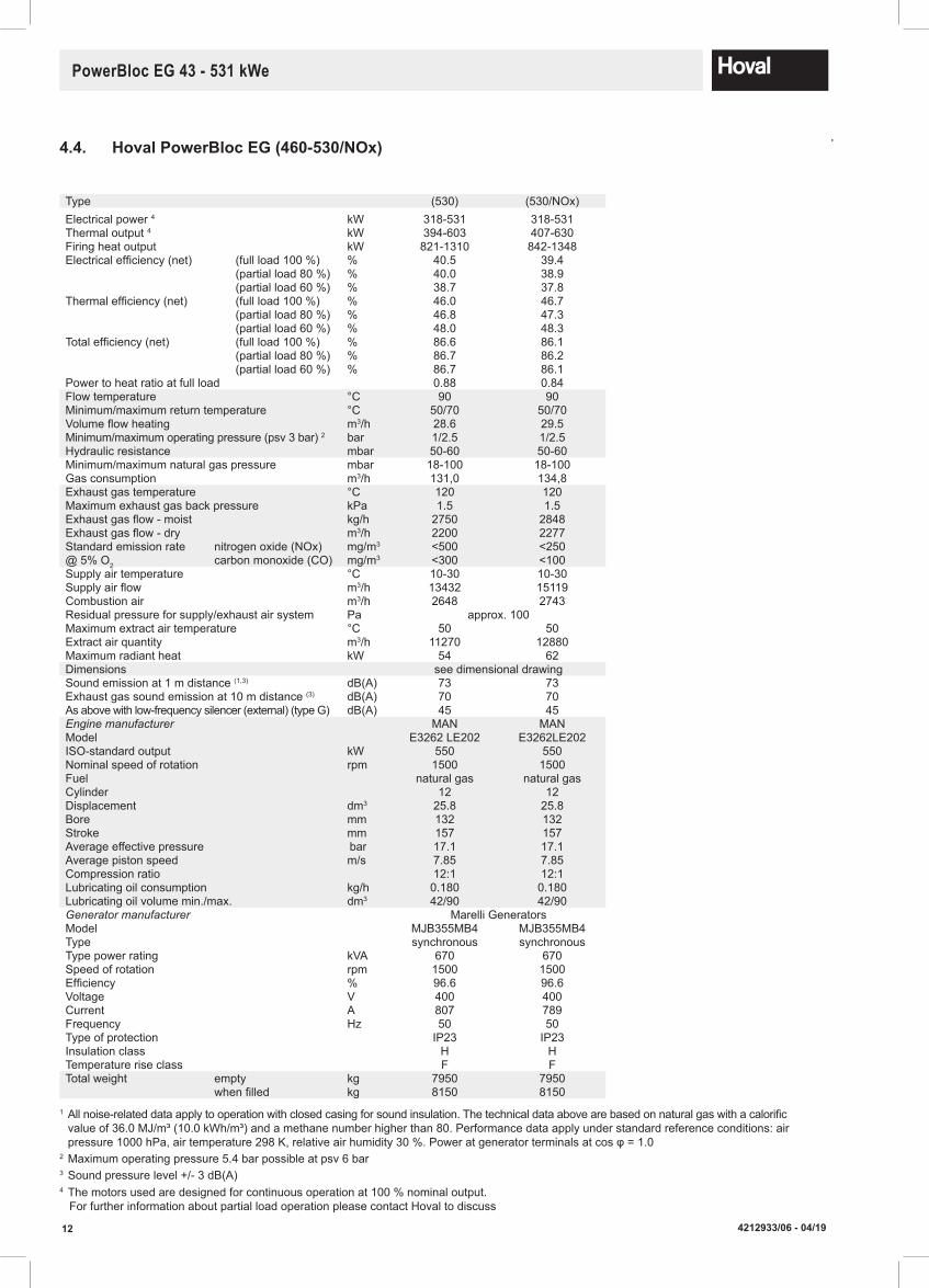
4.4. Hoval PowerBloc EG (460-530/NOx)
Type (530) (530/NOx)Electrical power 4 kW 318-531 318-531Thermal output 4 kW 394-603 407-630Firing heat output kW 821-1310 842-1348Electrical efficiency (net) (full load 100 %) % 40.5 39.4
(partial load 80 %) % 40.0 38.9(partial load 60 %) % 38.7 37.8
Thermal efficiency (net) (full load 100 %) % 46.0 46.7(partial load 80 %) % 46.8 47.3(partial load 60 %) % 48.0 48.3
Total efficiency (net) (full load 100 %) % 86.6 86.1(partial load 80 %) % 86.7 86.2(partial load 60 %) % 86.7 86.1
Power to heat ratio at full load 0.88 0.84Flow temperature °C 90 90Minimum/maximum return temperature °C 50/70 50/70Volume flow heating m3/h 28.6 29.5Minimum/maximum operating pressure (psv 3 bar) 2 bar 1/2.5 1/2.5Hydraulic resistance mbar 50-60 50-60Minimum/maximum natural gas pressure mbar 18-100 18-100Gas consumption m3/h 131,0 134,8Exhaust gas temperature °C 120 120Maximum exhaust gas back pressure kPa 1.5 1.5Exhaust gas flow - moist kg/h 2750 2848Exhaust gas flow - dry m3/h 2200 2277Standard emission rate nitrogen oxide (NOx) mg/m3 <500 <250@ 5% O2 carbon monoxide (CO) mg/m3 <300 <100Supply air temperature °C 10-30 10-30Supply air flow m3/h 13432 15119Combustion air m3/h 2648 2743Residual pressure for supply/exhaust air system Pa approx. 100Maximum extract air temperature °C 50 50Extract air quantity m3/h 11270 12880Maximum radiant heat kW 54 62Dimensions see dimensional drawingSound emission at 1 m distance (1,3) dB(A) 73 73Exhaust gas sound emission at 10 m distance (3) dB(A) 70 70As above with low-frequency silencer (external) (type G) dB(A) 45 45Engine manufacturer MAN MANModel E3262 LE202 E3262LE202ISO-standard output kW 550 550Nominal speed of rotation rpm 1500 1500Fuel natural gas natural gasCylinder 12 12Displacement dm3 25.8 25.8Bore mm 132 132Stroke mm 157 157Average effective pressure bar 17.1 17.1Average piston speed m/s 7.85 7.85Compression ratio 12:1 12:1Lubricating oil consumption kg/h 0.180 0.180Lubricating oil volume min./max. dm3 42/90 42/90Generator manufacturer Marelli Generators Model MJB355MB4 MJB355MB4Type synchronous synchronousType power rating kVA 670 670Speed of rotation rpm 1500 1500Efficiency % 96.6 96.6Voltage V 400 400Current A 807 789Frequency Hz 50 50Type of protection IP23 IP23Insulation class H HTemperature rise class F FTotal weight empty kg 7950 7950 when filled kg 8150 8150
1 All noise-related data apply to operation with closed casing for sound insulation. The technical data above are based on natural gas with a calorific value of 36.0 MJ/m³ (10.0 kWh/m³) and a methane number higher than 80. Performance data apply under standard reference conditions: air pressure 1000 hPa, air temperature 298 K, relative air humidity 30 %. Power at generator terminals at cos φ = 1.02 Maximum operating pressure 5.4 bar possible at psv 6 bar3 Sound pressure level +/- 3 dB(A)4 The motors used are designed for continuous operation at 100 % nominal output. For further information about partial load operation please contact Hoval to discuss
134212933/06 - 04/19
PowerBloc EG 43 - 531 kWe
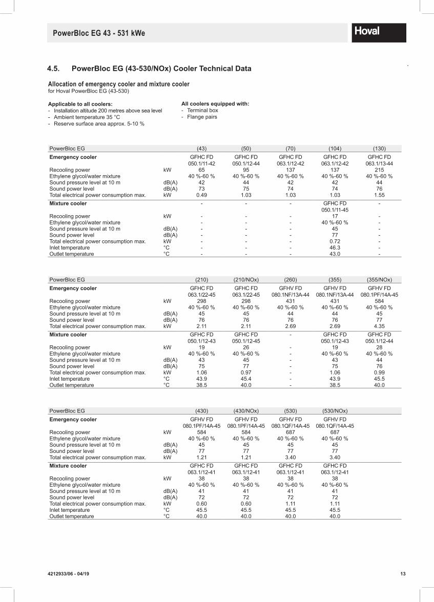
4.5. PowerBloc EG (43-530/NOx) Cooler Technical Data
Allocation of emergency cooler and mixture cooler for Hoval PowerBloc EG (43-530)
Applicabletoallcoolers: - Installation altitude 200 metres above sea level - Ambient temperature 35 °C - Reserve surface area approx. 5-10 %
Allcoolersequippedwith: - Terminal box - Flange pairs
PowerBloc EG (43) (50) (70) (104) (130)Emergencycooler GFHC FD
050.1/11-42GFHC FD
050.1/12-44GFHC FD
063.1/12-42GFHC FD
063.1/12-42GFHC FD
063.1/13-44Recooling power kW 65 95 137 137 215Ethylene glycol/water mixture 40 %-60 % 40 %-60 % 40 %-60 % 40 %-60 % 40 %-60 %Sound pressure level at 10 m dB(A) 42 44 42 42 44Sound power level dB(A) 73 75 74 74 76Total electrical power consumption max. kW 0.49 1.03 1.03 1.03 1.55Mixturecooler - - - GFHC FD
050.1/11-45-
Recooling power kW - - - 17 -Ethylene glycol/water mixture - - - 40 %-60 % -Sound pressure level at 10 m dB(A) - - - 45 -Sound power level dB(A) - - - 77 -Total electrical power consumption max. kW - - - 0.72 -Inlet temperature °C - - - 46.3 -Outlet temperature °C - - - 43.0 -
PowerBloc EG (210) (210/NOx) (260) (355) (355/NOx)Emergencycooler GFHC FD
063.1/22-45GFHC FD
063.1/22-45GFHV FD
080.1NF/13A-44GFHV FD
080.1NF/13A-44GFHV FD
080.1PF/14A-45Recooling power kW 298 298 431 431 584Ethylene glycol/water mixture 40 %-60 % 40 %-60 % 40 %-60 % 40 %-60 % 40 %-60 %Sound pressure level at 10 m dB(A) 45 45 44 44 45Sound power level dB(A) 76 76 76 76 77Total electrical power consumption max. kW 2.11 2.11 2.69 2.69 4.35Mixturecooler GFHC FD
050.1/12-43GFHC FD
050.1/12-45- GFHC FD
050.1/12-43GFHC FD
050.1/12-44Recooling power kW 19 26 - 19 28Ethylene glycol/water mixture 40 %-60 % 40 %-60 % - 40 %-60 % 40 %-60 %Sound pressure level at 10 m dB(A) 43 45 - 43 44Sound power level dB(A) 75 77 - 75 76Total electrical power consumption max. kW 1.06 0.97 - 1.06 0.99Inlet temperature °C 43.9 45.4 - 43.9 45.5Outlet temperature °C 38.5 40.0 - 38.5 40.0
PowerBloc EG (430) (430/NOx) (530) (530/NOx)Emergencycooler GFHV FD
080.1PF/14A-45GFHV FD
080.1PF/14A-45GFHV FD
080.1QF/14A-45GFHV FD
080.1QF/14A-45Recooling power kW 584 584 687 687Ethylene glycol/water mixture 40 %-60 % 40 %-60 % 40 %-60 % 40 %-60 %Sound pressure level at 10 m dB(A) 45 45 45 45Sound power level dB(A) 77 77 77 77Total electrical power consumption max. kW 1.21 1.21 3.40 3.40Mixturecooler GFHC FD
063.1/12-41GFHC FD
063.1/12-41GFHC FD
063.1/12-41GFHC FD
063.1/12-41Recooling power kW 38 38 38 38Ethylene glycol/water mixture 40 %-60 % 40 %-60 % 40 %-60 % 40 %-60 %Sound pressure level at 10 m dB(A) 41 41 41 41Sound power level dB(A) 72 72 72 72Total electrical power consumption max. kW 0.60 0.60 1.11 1.11Inlet temperature °C 45.5 45.5 45.5 45.5Outlet temperature °C 40.0 40.0 40.0 40.0

14 4212933/06 - 04/19
PowerBloc EG 43 - 531 kWe
4.6. PowerBlocEG(43-50)Dimensions
2380
3090
150
1770
Ø 530
2015
1200
960
1830
80
447 1326
Platzbedarf für Service
125
149
260
297
135 30
0
168
210 350 170
460
3 8
min
.100
0
P latzbedarf für Zu-/ Abluft
1500 1200
1000
1000
1
2
4
6
5 3
3
500
180
9
7
1 Heating flow Rp 1¼″/PN 62 Heating return Rp 1¼″/PN 63 Gas connection Rp ¾″4 Exhaust gas connection DN 80/PN 105 Condensate connection left
(stainless steel)22x1 mm
6 Condensate connection right (stainless steel)
22x1 mm
7 Drain ½″8 Supply air9 Extract air
Space requirement for supply/extract air
Space requirement for servicing

154212933/06 - 04/19
PowerBloc EG 43 - 531 kWe
4.7. PowerBlocEG(70)Dimensions
960
1830
560
1200
550
2840
2035
217
240
1812
351 2138
460
Platzbedarf für Service
3550
98
min
.100
0
1000
1000
200
12001500
Platzbedarf für Zu-/ Abluft
500
3
3
615
175
275
320
135
124
194 345
3
45
7
21
6
300
141
Space requirement for supply/extract air
Space requirement for servicing
1 Heating flow Rp 1¼″/PN 6 2 Heating return Rp 1¼″/PN 6 3 Gas connection 1″4 Exhaust gas connection DN 100/PN 105 Condensate connection left
(stainless steel)22x1 mm
6 Condensate connection right (stainless steel)
22x1 mm
7 Drain ½″8 Supply air9 Extract air

16 4212933/06 - 04/19
PowerBloc EG 43 - 531 kWe
4.8. PowerBlocEG(104)Dimensions
S180
U
L
190
D
590
1600
350
240
3200
20302235
340G
N O QP
325
X Z
W
Platzbedarf für Service
I
10 9
1000
1000
1500 1200
162
min
.100
0861
540*
Platzbedarf für Zu-/ Abluft
T
3
3
421
560
3758
6
M
* nur EG (104)
V135
Hoval PowerBloc EG (104)(Dimensions in mm)
Type D G I L M N O PEG(104) 1160 3960 1933 125 135 196 225 140
Type Q S T U V W X ZEG(104) 280 345 310 320 125 550 398 2403
Space requirement for supply/extract air
Space requirement for servicing
1 Heating flow Rp 1¼″/PN 6 2 Heating return Rp 1¼″/PN 6 3 Gas connection 1″4 Exhaust gas connection DN 100/PN 105 Condensate connection left
(stainless steel)22x1 mm
6 Condensate connection right (stainless steel)
22x1 mm
7 Drain ½″8 Supply air9 Extract air

174212933/06 - 04/19
PowerBloc EG 43 - 531 kWe
4.9. Hoval PowerBloc EG (130)(Dimensions in mm)
Type D G I L M N O PEG(130) 1360 4144 4210 125 114 252 450 -
Type Q S T U V W X ZEG
(130) - 335 347 328 133 630 458 2275
1 Heating flow Rp 2″/PN 62 Heating return Rp 2″/PN 63 Gas connection Rp 1½″4 Exhaust gas connection DN 125/PN 105 Condensate connection left
(stainless steel)22x1 mm
6 Condensate connection right (stainless steel)
22x1 mm
7 Drain ½″8 Supply air9 Extract air
Space requirement for supply/extract air
Space requirement for servicing
18 4212933/06 - 04/19
PowerBloc EG 43 - 531 kWe
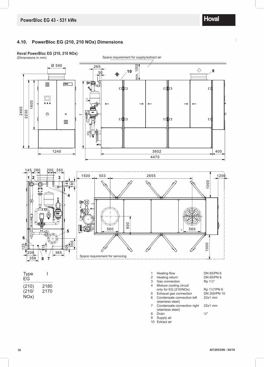
4.10. PowerBlocEG(210,210NOx)Dimensions
280
125
115
200358
105
365
350
200
3602
1600
Ø 590
22302465
1240
560 560
503 2655145 350
4004470
600
Platzbedarf für Service
26550
I
10 9
1000
1000
1500 1200
min
.100
0
185
P latzbedarf für Zu-/ Abluft
148
4
321
5
8
6
7
Hoval PowerBloc EG (210, 210 NOx)(Dimensions in mm)
1 Heating flow DN 65/PN 62 Heating return DN 65/PN 63 Gas connection Rp 1½″4 Mixture cooling circuit
only for EG (210/NOx) Rp 1¼″/PN 65 Exhaust gas connection DN 200/PN 106 Condensate connection left
(stainless steel)22x1 mm
7 Condensate connection right (stainless steel)
22x1 mm
8 Drain ½″9 Supply air10 Extract air
Type IEG(210) 2180(210/NOx)
2170
Space requirement for servicing
Space requirement for supply/extract air

194212933/06 - 04/19
PowerBloc EG 43 - 531 kWe
4.11. PowerBlocEG(260-530/NOx)Dimensions
Hoval PowerBloc EG (260-530/NOx)(Dimensions in mm)
6 Condensate connection left (stainless steel)
22x1 mm
7 Condensate connection right (stainless steel)
22x1 mm
8 Drain ½″9 Supply air
10 Extract air
1 Heating flow DN 65/ PN 6, EG (240,260)DN 80/ PN 6, EG (355-530)
2 Heating return DN 65/ PN 6, EG (240,260)DN 80/ PN 6, EG (355-530)
3 Gas connection Rp 2″, EG (260-430)DN 65/ PN 16, EG (530)
4 Mixture cooling Rp 1¼″, EG (355)circuit Rp 1½″, EG (430)
Rp 1½″/ PN 6, EG (530)5 Exhaust gas DN 200/ PN 10, EG (260)
connection DN 250/PN 10, EG (355,430)DN 300/PN 10, EG (530)
Mixture cooling circuit only for EG (355,430,530)
L
M
U
VK
R
Q
N P
T
S
H
E
1200D
C16
00B
A
J
400FG
I
8
1 2
34
5
min
.10
00
10 9
Y YW
X Z 1200
1000
1000
6
1500
7
Platzbedarf für Zu-/ Abluft
Platzbedarf für Service
B ir a l ®
Space requirement for supply/extract air
Space requirement for servicing
Type W X Y ZEG(260) 800 380 620 3048(355) 860 450 690 3597(430) 925 500 770 3996(530) 925 500 770 3996
Type A B C D E F G H I J K L M N P Q R S T U VEG Ø(260) 2465 2230 345 1640 650 3800 4720 - 2069 311 200 255 355 270 650 200 - 365 365 160 370(355) 2765 2530 655 1640 720 4500 4820 - 2512 317 300 150 390 368 300 300 - 460 460 230 460(430) 2765 2530 950 1760 800 5000 5680 - 2460 315 300 220 460 300 300 300 - 460 460 150 428(530) 2890 2630 950 1890 800 5000 6120 300 2460 315 300 219 460 300 300 300 600 460 460 150 428
Connection dimensions subject to technical modifications

20 4212933/06 - 04/19
PowerBloc EG 43 - 531 kWe
4.12. DimensionsforEmergencycoolers(EG43-210)
Emergency coolerfor Hoval PowerBloc EG (210,210/NOx)(Dimensions in mm)
Emergency coolerfor Hoval PowerBloc EG (43)(Dimensions in mm)
Emergency coolerfor Hoval PowerBloc EG (50,70,104)(Dimensions in mm)
Masse in mm
Gewichte in kg
*Losflansche PN10 mit Lötbördel
R 000 534 / 01
15.09.2016 / MILESeite 1 von 2
BHKW-Typ Typ D H H1 L L1 W W1 Gewicht Anschlussgrösse*
EG-210/80 / EG-210 / EG-210 Nox GFHC FD 063.1/22-45 13 924 400 2469 2300 2096 2056 357 54 x 2
BHKW-Typ Typ D H H1 L L1 W W1 Gewicht Anschlussgrösse*
EG-50 GFHC FD 050.1/12-44 13 919 400 1869 1700 888 848 132 35 x 1,5
EG-70 / EG-140 GFHC FD 063.1/12-42 13 924 400 2469 2300 1088 1048 177 42 x 1,6
BHKW-Typ Typ D H H1 L L1 W W1 Gewicht Anschlussgrösse*
EG-20 / EG-43 GFHC FD 050.1/11-42 13 919 400 1269 1100 1088 1048 103 28 x 1,5
L
L 1
D
H
H1
W
W 1
L 1
L
D
W 1
W
H1
H
L 1
L
D
H1
W 1
H
W
PowerBloc EG type D H H1 L L1 W W1 Weight Connection 1)
type kg
(43) GFHC FD 050.1/11-42 13 919 400 1269 1100 1088 1048 103 28 x 1.5
1 Mating flange PN 10 with soldering flange
Masse in mm
Gewichte in kg
*Losflansche PN10 mit Lötbördel
R 000 534 / 01
15.09.2016 / MILESeite 1 von 2
BHKW-Typ Typ D H H1 L L1 W W1 Gewicht Anschlussgrösse*
EG-210/80 / EG-210 / EG-210 Nox GFHC FD 063.1/22-45 13 924 400 2469 2300 2096 2056 357 54 x 2
BHKW-Typ Typ D H H1 L L1 W W1 Gewicht Anschlussgrösse*
EG-50 GFHC FD 050.1/12-44 13 919 400 1869 1700 888 848 132 35 x 1,5
EG-70 / EG-140 GFHC FD 063.1/12-42 13 924 400 2469 2300 1088 1048 177 42 x 1,6
BHKW-Typ Typ D H H1 L L1 W W1 Gewicht Anschlussgrösse*
EG-20 / EG-43 GFHC FD 050.1/11-42 13 919 400 1269 1100 1088 1048 103 28 x 1,5
L
L 1
D
H
H1
W
W 1
L 1
L
D
W 1
W
H1
H
L 1
L
D
H1
W 1
H
W
PowerBloc EG type D H H1 L L1 W W1 Weight Connection 1)
type kg
(50) GFHC FD 050.1/12-44 13 919 400 1869 1700 888 848 132 35 x 1.5(70,104) GFHC FD 063.1/12-42 13 924 400 2469 2300 1088 1048 177 42 x 1.6
1 Mating flange PN 10 with soldering flange
PowerBloc EG type D H H1 L L1 W W1 Weight Connection 1)
type kg
(210,210/NOx) GFHC FD 063.1/22-45 13 924 400 2469 2300 2096 2056 357 54 x 2
1 Mating flange PN 10 with soldering flange
Masse in mm
Gewichte in kg
*Losflansche PN10 mit Lötbördel
R 000 534 / 01
15.09.2016 / MILESeite 1 von 2
BHKW-Typ Typ D H H1 L L1 W W1 Gewicht Anschlussgrösse*
EG-210/80 / EG-210 / EG-210 Nox GFHC FD 063.1/22-45 13 924 400 2469 2300 2096 2056 357 54 x 2
BHKW-Typ Typ D H H1 L L1 W W1 Gewicht Anschlussgrösse*
EG-50 GFHC FD 050.1/12-44 13 919 400 1869 1700 888 848 132 35 x 1,5
EG-70 / EG-140 GFHC FD 063.1/12-42 13 924 400 2469 2300 1088 1048 177 42 x 1,6
BHKW-Typ Typ D H H1 L L1 W W1 Gewicht Anschlussgrösse*
EG-20 / EG-43 GFHC FD 050.1/11-42 13 919 400 1269 1100 1088 1048 103 28 x 1,5
L
L 1
D
H
H1
W
W 1
L 1
L
D
W 1
W
H1
H
L 1
L
D
H1
W 1
H
W
214212933/06 - 04/19
PowerBloc EG 43 - 531 kWe
PowerBloc EG type D H H1 L L1 W W1 Weight Connection 1)
type kg
(50) GFHC FD 050.1/12-44 13 919 400 1869 1700 888 848 132 35 x 1.5(70,104) GFHC FD 063.1/12-42 13 924 400 2469 2300 1088 1048 177 42 x 1.6
1 Mating flange PN 10 with soldering flange
PowerBloc EG type D H H1 L L1 W W1 Weight Connection 1)
type kg
(210,210/NOx) GFHC FD 063.1/22-45 13 924 400 2469 2300 2096 2056 357 54 x 2
1 Mating flange PN 10 with soldering flange
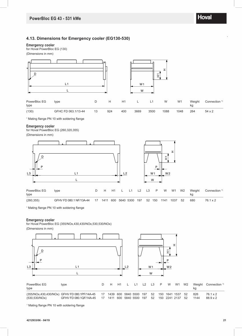
4.13.DimensionsforEmergencycooler(EG130-530)Emergency cooler for Hoval PowerBloc EG (130)(Dimensions in mm)
Emergency cooler for Hoval PowerBloc EG (260,320,355)(Dimensions in mm)
PowerBloc EG type D H H1 L L1 W W1 Weight Connection 1)
type kg
(130) GFHC FD 063.1/13-44 13 924 400 3669 3500 1088 1048 264 54 x 2
1 Mating flange PN 10 with soldering flange
PowerBloc EG type D H H1 L L1 L2 L3 P W W1 W2 Weight Connection 1)
type kg
(260,355) GFHV FD 080.1 NF/13A-44 17 1411 600 5640 5300 197 52 150 1141 1037 52 680 76.1 x 2
1 Mating flange PN 10 with soldering flange
*Losflansche PN10 mit Lötbördel
Masse in mm
Gewichte in kg
R 000 534 / 01
15.09.2016 / MILESeite 2 von 2
L 1
L
D
W 1
W
H1
H
P
L 3 L 2L 1
L
D
W 1 W 2
W
P
H1
H
BHKW-Typ Typ D H H1 L L1 W W1 Gewicht Anschlussgrösse*
EG-140 GFHC FD 063.1/13-44 13 924 400 3669 3500 1088 1048 264 54 x 2
BHKW-Typ Typ D H H1 L L1 L2 L3 P W W1 W2 Gewicht Anschlussgrösse*
EG-320 / EG-355 GFHV FD 080.1 NF/13A-44 17 1411 600 5640 5300 197 52 150 1141 1037 52 680 76,1 x 2
L 1
L
D
W
W 1
H
H1
P
L 3 L 1 L 2
L
D
P
W 2W 1
W
H1
H
BHKW-Typ Typ D H H1 L L1 W W1 Gewicht Anschlussgrösse*
EG-240 / EG-250 GFHC FD 050.1/24-43 13 1146 600 3669 3500 1696 1656 496 64 x 2
BHKW-Typ Typ D H H1 L L1 L2 L3 P W W1 W2 Gewicht Anschlussgrösse*
EG-355 Nox / EG-404 / EG-460 GFHV FD 080.1PF/14A-45 13 1439 600 5840 5500 197 52 150 1641 1537 52 826 76,1 x 2
EG-530 / EG-530 Nox GFHV FD 080.1QF/14A-45 17 1411 600 5840 5500 197 52 150 2241 2137 52 1144 88,9 x 2
*Losflansche PN10 mit Lötbördel
Masse in mm
Gewichte in kg
R 000 534 / 01
15.09.2016 / MILESeite 2 von 2
L 1
L
D
W 1
W
H1
H
P
L 3 L 2L 1
L
D
W 1 W 2
W
PH
1
H
BHKW-Typ Typ D H H1 L L1 W W1 Gewicht Anschlussgrösse*
EG-140 GFHC FD 063.1/13-44 13 924 400 3669 3500 1088 1048 264 54 x 2
BHKW-Typ Typ D H H1 L L1 L2 L3 P W W1 W2 Gewicht Anschlussgrösse*
EG-320 / EG-355 GFHV FD 080.1 NF/13A-44 17 1411 600 5640 5300 197 52 150 1141 1037 52 680 76,1 x 2
L 1
L
D
W
W 1
H
H1
P
L 3 L 1 L 2
L
D
P
W 2W 1
W
H1
H
BHKW-Typ Typ D H H1 L L1 W W1 Gewicht Anschlussgrösse*
EG-240 / EG-250 GFHC FD 050.1/24-43 13 1146 600 3669 3500 1696 1656 496 64 x 2
BHKW-Typ Typ D H H1 L L1 L2 L3 P W W1 W2 Gewicht Anschlussgrösse*
EG-355 Nox / EG-404 / EG-460 GFHV FD 080.1PF/14A-45 13 1439 600 5840 5500 197 52 150 1641 1537 52 826 76,1 x 2
EG-530 / EG-530 Nox GFHV FD 080.1QF/14A-45 17 1411 600 5840 5500 197 52 150 2241 2137 52 1144 88,9 x 2
Emergency cooler for Hoval PowerBloc EG (355/NOx,430,430/NOx,530,530/NOx)(Dimensions in mm)
PowerBloc EG type D H H1 L L1 L2 L3 P W W1 W2 Weight Connection 1)
type kg
(355/NOx,430,430/NOx) GFHV FD 080.1PF/14A-45 17 1439 600 5840 5500 197 52 150 1641 1537 52 826 76.1 x 2(530,530/NOx) GFHV FD 080.1QF/14A-45 17 1411 600 5840 5500 197 52 150 2241 2137 52 1144 88.9 x 2
1 Mating flange PN 10 with soldering flange*Losflansche PN10 mit Lötbördel
Masse in mm
Gewichte in kg
R 000 534 / 01
15.09.2016 / MILESeite 2 von 2
L 1
L
D
W 1
W
H1
H
P
L 3 L 2L 1
L
D
W 1 W 2
W
P
H1
H
BHKW-Typ Typ D H H1 L L1 W W1 Gewicht Anschlussgrösse*
EG-140 GFHC FD 063.1/13-44 13 924 400 3669 3500 1088 1048 264 54 x 2
BHKW-Typ Typ D H H1 L L1 L2 L3 P W W1 W2 Gewicht Anschlussgrösse*
EG-320 / EG-355 GFHV FD 080.1 NF/13A-44 17 1411 600 5640 5300 197 52 150 1141 1037 52 680 76,1 x 2
L 1
L
D
W
W 1
H
H1
P
L 3 L 1 L 2
L
D
P
W 2W 1
W
H1
H
BHKW-Typ Typ D H H1 L L1 W W1 Gewicht Anschlussgrösse*
EG-240 / EG-250 GFHC FD 050.1/24-43 13 1146 600 3669 3500 1696 1656 496 64 x 2
BHKW-Typ Typ D H H1 L L1 L2 L3 P W W1 W2 Gewicht Anschlussgrösse*
EG-355 Nox / EG-404 / EG-460 GFHV FD 080.1PF/14A-45 13 1439 600 5840 5500 197 52 150 1641 1537 52 826 76,1 x 2
EG-530 / EG-530 Nox GFHV FD 080.1QF/14A-45 17 1411 600 5840 5500 197 52 150 2241 2137 52 1144 88,9 x 2
22 4212933/06 - 04/19
PowerBloc EG 43 - 531 kWe
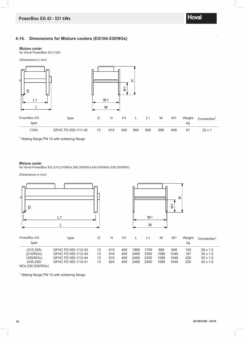
Mixture cooler for Hoval PowerBloc EG (104)
(Dimensions in mm)
Mixture cooler for Hoval PowerBloc EG (210,210/NOx,355,355/NOx,430,430/NOx,530,530/NOx)
(Dimensions in mm)
4.14. DimensionsforMixturecoolers(EG104-530/NOx)
PowerBloc EG type D H H1 L L1 W W1 Weight Connection1
type kg
(104) GFHC FD 050.1/11-45 13 919 400 969 800 888 848 67 22 x 1
1 Mating flange PN 10 with soldering flange
PowerBloc EG type D H H1 L L1 W W1 Weight Connection1
type kg
(210,355) GFHC FD 050.1/12-43 13 919 400 1869 1700 888 848 155 28 x 1,5(210/NOx) GFHC FD 050.1/12-45 13 919 400 2469 2300 1088 1048 187 35 x 1,5(355/NOx) GFHC FD 050.1/12-44 13 919 400 2469 2300 1088 1048 206 35 x 1,5(430,430/
NOx,530,530/NOx)GFHC FD 063.1/12-41 13 924 400 2469 2300 1088 1048 226 42 x 1,6
1 Mating flange PN 10 with soldering flange

234212933/06 - 04/19
PowerBloc EG 43 - 531 kWe
4.15. Dimensionsforsecondarysilencers(EG43-530)
Low-frequency silencer G(Dimensions in mm)
Low-frequency silencer S(Dimensions in mm)
PowerBloc EG A B C D E F G H 1 Exhaust gas inlet 2 Exhaust gas outlet 3 Condensate Weighttype DN PN DN PN outlet kg
(43,50) 205 1500 150 600 50 300 100 1855 80 10 80 10 R 1″ 112(70) 210 1750 150 600 75 320 100 2110 100 10 100 10 R 1″ 123(104,130) 205 2000 150 600 95 325 100 2355 125 10 125 10 R 1″ 139(210) 300 2200 150 700 30 500 100 2650 200 10 200 10 R 1″ 182(355,430) 300 2250 150 750 40 500 100 2700 250 10 250 10 R 1″ 215(530) 300 2500 150 800 30 520 100 2950 300 10 300 10 R 1″ 254
PowerBloc EG A B C D E F G H 1 Exhaust gas inlet 2 Exhaust gas outlet 3 Condensate Weighttype DN PN DN PN outlet kg
(43,50) 205 1500 150 500 50 300 100 1855 80 10 80 10 R 1″ 58(70) 210 1750 150 500 75 320 100 2110 100 10 100 10 R 1″ 67(104,130) 205 2000 150 500 95 325 100 2355 125 10 125 10 R 1″ 75(210) 300 2200 150 600 30 500 100 2650 200 10 200 10 R 1″ 118(355,430) 300 2250 150 650 40 500 100 2700 250 10 250 10 R 1″ 131(530) 300 2500 150 650 30 520 100 2950 300 10 300 10 R 1″ 148
HC
BA
G
D
FE
2
3
1
HC
B
D
A
G
FE
2
3
1
Pressuredrop
PowerBloc EG Low-frequency Pressure droptype silencer Pa
(43) (S-080) 33(50) (S-080) 45(70) (S-100) 25(104) (S-125) 53(130) (S-125) 59(210) (S-200) 23(260) (S-200) 12(355) (S-250) 31(430) (S-250) 20(530) (S-300) 21
Pressuredrop
PowerBloc EG Low-frequency Pressure droptype silencer Pa
(43) (G-080) 33(50) (G-080) 45(70) (G-100) 25(104) (G-125) 53(130) (G-125) 59(210) (G-200) 23(260) (G-200) 12(355) (G-250) 31(430) (G-250) 20(530) (G-300) 21(530) (G-300) 21
Connection dimensions subject to technical modifications
24 4212933/06 - 04/19
PowerBloc EG 43 - 531 kWe
NotesoninstallationandtheOperationoftheCHPplantRegular preventative maintenance needs to be performed on the CHP plant to ensure it operates correctly. As well as these scheduled service visits the site operator needs to frequently check the CHP plant to ensure that everything is operating as designed.
5.1. SiteRequirements
• A suitable flat, solid, level and fire proof base must be provided to suit the flooded weight of the CHP plant concerned (not provided by Hoval).
• The CHP plant must be installed by competent persons and in accordance with the assembly instructions.
• The CHP plant must be commissioned by Hoval.• All building regulations must be adhered to in regards to the installation, the air duct work and the flue
arrangement.• All electrical regulations must be adhered to when connecting the power (i.e. G59/3 application must be
completed).• The relevant Gas standards must be adhered to when connecting the gas pipe-work.• All regulations with regard to the heating water system must be adhered to. • All health & safety regulations applicable to the plant must be adhered to at all times.• The Heating system must be pressurised between 1-2.5 bar (1-5.5 bar for high pressure modules).• Suitable rated outgoing power to be connected to CHP as well as a 32A 3Phase and Neutral supply.• Tomaintainthebestoperatingefficienciesandavoidprematurewear,theCHPhasaminimum
runtimeofthreehours.
5.2. AdditionalNotesfortheInstaller
When installing your new CHP plant you need to be aware of several items:
VibrationInsulationMat
Rubber Vibration Insulation Matting is provided with the CHP plant, supplied loose. When the CHP is sited these insulation strips must be placed under the framework of the skid arrangement before services are con-nected.
FlexiblePipeConnections
It is imperative that the incoming gas pipe, the heating system flow pipe, the heating system return pipe and the exhaust connection are all connected to the CHP skid with flexible connections. This is so vibration from the engine is not transmitted through the pipework back through the building.
CondensateDrains
The condensate from the exhaust connection must be piped to drain in stainless steel or a suitable plastic. A suitable trap must be fitted in line before reaching the drain point. Note this must all be done in stainless steel or a suitable plastic.
ElectricalConnections/CableManagement
Any links between the CHP plant and the cable management must be done so with flexible connections. All cable management (trunking, conduit, cable tray) must not be rigidly fixed to the CHP plant.
ExistingElectricalSupply
Please be aware the voltage on site must be within the tolerances of the current standards. The electrical loadings on each phase must be within 10% of one another. For example if L1 is 1000A then L2 and L3 must be between 910A and 1000A or 1000A and 1100A.
Un-commissionedCHP
Please be aware the CHP should be commissioned within 6 months from date of delivery as the corrosion protection is limited. Should further time be required then Hoval will be able to offer a quotation to attend site and re-protect the necessary surfaces. (see section 12.6 for further information)
5. InstallationRequirements

254212933/06 - 04/19
PowerBloc EG 43 - 531 kWe
Ventilation
Ventilation can be done in either of two ways, the first being open to the plantroom and secondly as a room-sealed device. If the inlet and extract air ventilation connections are open to the plant room then the plant room must have suitable ventilation as per BS6644. If this does not suit the installation both connections can be ducted to an external wall (with a minimum distance of 1m between inlet and extract connection. In all installations the maximum temperatures stated in BS6644 must be adhered to.
Catalytic Converter
A catalytic converter is supplied loose and is designed to be fitted after 50-200 run hours. This must be stored in a safe location on site by the installer for fitting as above.
5.3. ReadinessforOperation
GasSupply
A supply of gas at the required quality (see technical data table). This must be above the minimum pressure of 18mbar at full output, and at all times the CHP plant and other gas-fired equipment is operating.
LubricatingOilintheEngine
The engine oil must always be filled to the correct level with a suitable lubricant approved by MAN. Details of the oil specification can be found in the engine manual.
The CHP package is equipped with an oil storage tank inside the cabinet for automatic lubrication oil top-up. This is to replenish burnt oil during operation and tops up the engine oil starting at a pre-determined level set at commissioning. The oil storage tank will be filled at the first 50hr running in service, after which the opera-tor should check this tank regularly to ensure it is topped up. It is not to become empty.
CoolingWater
The coolant must be maintained at the required level. The coolant circuit is pressurised so must remain sealed at all times. The coolant must be to the appropriate standard as specified in the engine manual to ensure adequate protection against corrosion.
HeatingWater
The heating water circuit to extract heat from the CHP plant must meet the minimum quality (see detailed specification further in the manual). The circulation pump for this circuit must be operational and above the stated minimum flow rate.
Starter Battery
The battery should always be fully charged and the fluid level maintained to its upper marking.
5.4. Further Important Information
• The installation of the CHP plant must be reported to and approved by the relevant energy supply companies. (G59 / Electrical Distribution Network Operator).
• Certificates must be available prior to commissioning from the appropriate specialists for the gas purge test and also a pressure test for the exhaust system.
• Approval must be sought before piping the condensate to drain.
5.5. WasteDisposal
The disposal of any un-needed items such as packaging should be done so in an environmentally friendly manner.Upon servicing the waste lubricating oil must be disposed of correctly. Proof of disposal must be documented and archived.WasteoilwillnotbedisposedofbyHoval.
Modifications
Modifications to the CHP plant without written approval are not permitted.

26 4212933/06 - 04/19
PowerBloc EG 43 - 531 kWe
6. WaterQuality
– European standard BSEN 14868:2005 and VDI guideline 2035 must be observed. Particular note must be taken of the following regulations.
– Hoval CHP plant, boilers and water heaters are suitable for heating systems without significant oxygenation (system type 1 in accordance below with BSEN 14868:2005).
– Systems with – Continuousoxygen intake (e.g. underfloor heating without diffusion proof plastic piping) or – Intermittent oxygen intake (e.g. where frequent refilling is necessary) must be equipped with separate circuits.
– Treated heating water must be checked at least once per year or more frequently as specified by the inhibitor manufacturer.
– If, in the case of existing systems (e.g. heat generator replacement), the water quality of the existing heating water complies with VDI 2035, it is not recommended that the system be refilled. VDI 2035 also applies to top-up water.
– Before filling new systems, or, if applicable, existing systems, the heating system must be professionally cleaned and flushed. The heating system must be flushed before the CHP is filled.
– Components of the CHP plant that come into contact with water are made of ferrous materials and stainless steel.
– Due to the risk of stress corrosion cracking in the stainless steel component of the heat generator, the combined chloride, nitrate and sulphate content of the heating water must not exceed a total of 50mg/l. The limit for chloride is 30mg/l.
– Once the heating has been in operation for 6–12 weeks, the pH value of the heating water should be between 8.3 and 9.5.
6.1. HeatingWater
Electrical conductivity (µS) < 100Oxygen (O2) mg/l < 0.05Chloride mg/l < 30Copper (Cu) mg/l < 0.05Total Iron (Fe) mg/l < 0.05Alkaline earths mmol/l < 0.02Total hardness °dH < 0.1Phosphate (PO4) mg/l 5 - 10
– A suitable freezing-protection agent should be used, if the CHP plant and associated pipework are likely to be subjected to temperatures below 2°C.
Waterforfillingandtoppingupthesystem:
– For an installation using a Hoval CHP, untreated drinking water is generally best suited as the heating medium, i.e. as filling and replacement water. However, as not all drinking water is suitable for use as as filling and replacement water the water quality must fulfil the standard set in VDI 2035. Should the mains water available not be suited for use then it must be desalinated and/ or be treated with inhibitors. The stipulations of EN 14868 must be observed.
– In order to maintain a high level of efficiency and to avoid overheating of the heating surfaces the values given in the table should not be exceeded (dependent on heat generator performance ratings - for multi-heat generator installation, the rating of smallest boiler applies - and on the water content of the plant).
The total quantity of water used to fill and top up the system during the equipments life must not exceed a value equivalent of twice the water content of the system.
WaterSpecificationLimitValues
The European Standard EN 14868 and thedirectiveVDI2035mustbeobserved.

274212933/06 - 04/19
PowerBloc EG 43 - 531 kWe
7. TypicalPipeworkSchematics
Hydraulics Plant:
HCS-CHP-1
Notes:
drawn
File: HCS-CHP-2.vsd
Date Name14.03.12 RobGri
Attention!Thishydraulicschematiconlyshowsthebasicprinciplesanddoesnotshowalltheitemsoftheinstallation.Theinstallationmustbeinaccordancewithlocalregulations.Page 1 of 2
Pumps, Valves, Pipework and interconnecting wiring not by Hoval. Unless specified (see quote).
checked
Pipework Schematic
SVLF
AAV
Hoval
HovalPressVal
CWS
Dies ist ein unerlaubter Weg!Gehen Sie einen Schritt zurück oder löschen Sie dieses Shape!Sie haben die Möglichkeit ein neues Shape zu nehmen!!! hovhovalhhovalhovaalhovalho
P
UltraGas 2
M5.2
Dies ist ein unerlaubter Weg!Gehen Sie einen Schritt zurück oder löschen Sie dieses Shape!Sie haben die Möglichkeit ein neues Shape zu nehmen!!! hovhovalhhovalhovaalhovalho
P
UltraGas 1
M5.1
AAV AAV
P
AAV
M5.3 M5.4
Combined Heat and
PowerEnerVal
Thermal Store
P
AAV
YK1
Hydraulics Plant:
HCS-CHP-1
Notes:
drawn
File: HCS-CHP-1.vsd
Date Name14.03.12 RobGri
Attention!Thishydraulicschematiconlyshowsthebasicprinciplesanddoesnotshowalltheitemsoftheinstallation.Theinstallationmustbeinaccordancewithlocalregulations.Page 1 of 2
Pumps, Valves, Pipework and interconnecting wiring not by Hoval. Unless specified (see quote).
checked
Pipework Schematic
SVLF
Dies ist ein unerlaubter Weg!Gehen Sie einen Schritt zurück oder löschen Sie dieses Shape!Sie haben die Möglichkeit ein neues Shape zu nehmen!!! hovhovalhhovalhovaalhovalho
P
UltraGas 2
M5.4
Dies ist ein unerlaubter Weg!Gehen Sie einen Schritt zurück oder löschen Sie dieses Shape!Sie haben die Möglichkeit ein neues Shape zu nehmen!!! hovhovalhhovalhovaalhovalho
P
UltraGas 1
M5.3
AAV AAVAAV
P
AAV
M5.1 M5.2
CombinedHeat and
PowerEnerVal
Thermal Store
Hoval
HovalPressVal
CWS
P
AAV
YK1
7.1. CHP in Parallel The most efficient way of operating a CHP installation providing the Building Management System has the appropriate controls.
7.2. CHPinSeries The easiest way of fitting the CHP into building with a limited control system. This arrangement works by pre-heating the return to the boilers.
Note: Theaboveschematicsareindicativeandonlyshowthebasicprinciple.Allinstallationsshouldbeinaccordancewithlocalregulations.

28 4212933/06 - 04/19
PowerBloc EG 43 - 531 kWe
8.1. ConstructionofTheCHPPlant • A skid-mounted unit complete with a sound reduction casing or mounted within an insulated container
installed complete with heat exchangers and exhaust gas silencer.• Combustion air and all ventilation requirements are met with the fan-assisted inlet and extract air
system. • All pipe work to the flanged connections and the heat exchangers containing useful heat are fully
insulated.• Anti-vibration mounting points are used between the main frame of the skid and the engine and
generator assembly stopping nuisance vibrations being transferred through the unit.• Various information points and test points on the CHP plant are available on all of the water circuits and
on the exhaust system.
8.2. TheGasEngine
A MAN gas engine with spark ignition is used in the CHP plant. This engine has electronic speed control with automatic ignition complete with all required filtration, lubrication and cooling systems required. The full specification of the engine as follows:
• Crankcase with cylinder block in one piece, made of cast iron, sealed at the bottom by an oil sump and at the rear by the flywheel control housing
• Cylinder heads with moulded-in vortex intake ducts and valve seat inserts shrunk into the cylinder heads• Light alloy pistons, cooled by pressurised oil from oil injection nozzles• Angled connecting rods, a crankshaft with 7 bearings, steel-backed cast lead bronze bearing shells• Valves mounted vertically and with replaceable valve guides• One inlet valve and one outlet valve per cylinder, camshaft mounted on 7 bearings• Forced-feed lubrication with oil filter in the main flow and cooling by means of oil cooler• Automatic oil refill device• Crankshaft ventilation with oil separator and connection to combustion air• Closed-circuit engine cooling, pump with three-phase motor, safety valve and expansion tank• Air intake via dry-air filter, directly from the installation room via supply air device• Pre-engaged drive starter motor 24V• Electronic high-performance ignition with solid-state low-voltage distribution, one ignition coil per cylinder• Gas-air mixer, gas control damper for output and speed control• Actuator for speed and output control• Turbo-charger and intercooler (on some models)
8.3. The Generator
The main components of the generator are the internally-poled rotor and the wound stator complete with exciter circuit and voltage regulator using an auxiliary winding. The three-phase alternating voltage induced in the exciter circuit is rectified via the rotating diode disc and fed to the generator revolving field. Voltage stabilisation for the main generator under alternating loads is maintained by changing the field current via the thyristor actuator in the voltage regulator.
8. Construction
294212933/06 - 04/19
PowerBloc EG 43 - 531 kWe
8.4. EngineCoolingWaterHeatExchanger
The engine cooling water heat exchanger transfers the heat from the gas engine to the external heating wa-ter system. Inside the heat exchanger, the warm engine cooling water and the cooler heating water are in counterflow, ensuring optimum heat transfer. The heat exchanger hydraulically separates the cooling water and the heating water.
8.5. ExhaustGasHeatExchanger
In the exhaust gas heat exchanger, energy is recovered from the exhaust gas. The exhaust gas mass flow is routed over a water circuit flowing through the exhaust gas heat exchanger. The exhaust gas flows through the heat exchanger tubes on the primary side, thereby transferring its heat to the heating water (secondary side). The operating temperatures for the exhaust gas are approx. 600°C at the inlet and approx. 120°C at the outlet, and the operating temperature on the heating water side is approx. 90°C.
8.6. EngineCoolingCircuit
The cooling circuit of the gas engine is equipped with a separate expansion tank and pump which is routed via the engine cooling water heat exchanger. The engine cooling water is first routed into the cooling ducts of the engine housing, where it absorbs the transferred heat and then flows back into the engine cooling water heat exchanger. The engine cooling water heat exchanger transfers the heat to the heating water. The cooling water is always a mixture of antifreeze and a corrosion protection agent. For the full specification see the MAN manual.
8.7. HeatingWaterCircuit
The heating water circuit flows first through the engine cooling water heat exchanger and then through the exhaust gas heat exchanger. The CHP plant is equipped with a circulation pump which pumps a constant volume of water through the exchangers. In addition, a three-way valve is installed to regulate a constant return temperature of 70°C to the engine cooling water heat exchanger. The heat extraction system is also equipped with the relevant safety devices for temperature and pressure.
8.8. ExhaustCatalyticConvertor
The closed-loop three-way catalytic convertor and the oxidation catalyst in the case of turbocharged engines reduce the pollutants in the engine exhaust gases. To be fitted after 50-200 hours run time.
8.9. Ventilation
The CHP plant is equipped with a supply air fan which is operated in two stages. The first stage is designed to supply adequate combustion air to the engine and allow the radiant heat to be extracted. The second stage is switched on as required via a temperature sensor in the sound reduction capsule or container. The supply air is drawn in by a fan via an on-site supply air duct. The extract air should be routed to outdoors via an extract air duct (not by Hoval). Please refer to the technical data section for further information.
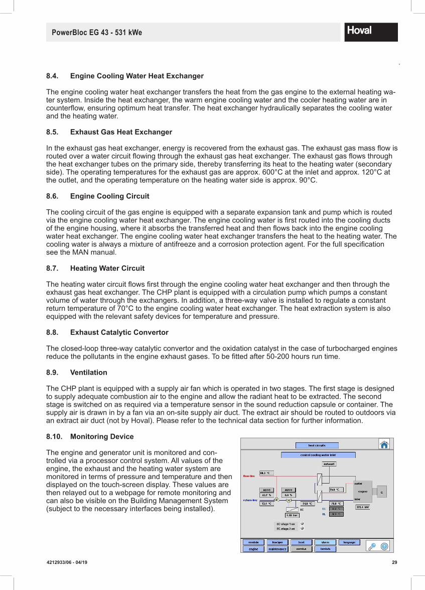
8.10. MonitoringDevice
The engine and generator unit is monitored and con-trolled via a processor control system. All values of the engine, the exhaust and the heating water system are monitored in terms of pressure and temperature and then displayed on the touch-screen display. These values are then relayed out to a webpage for remote monitoring and can also be visible on the Building Management System (subject to the necessary interfaces being installed).
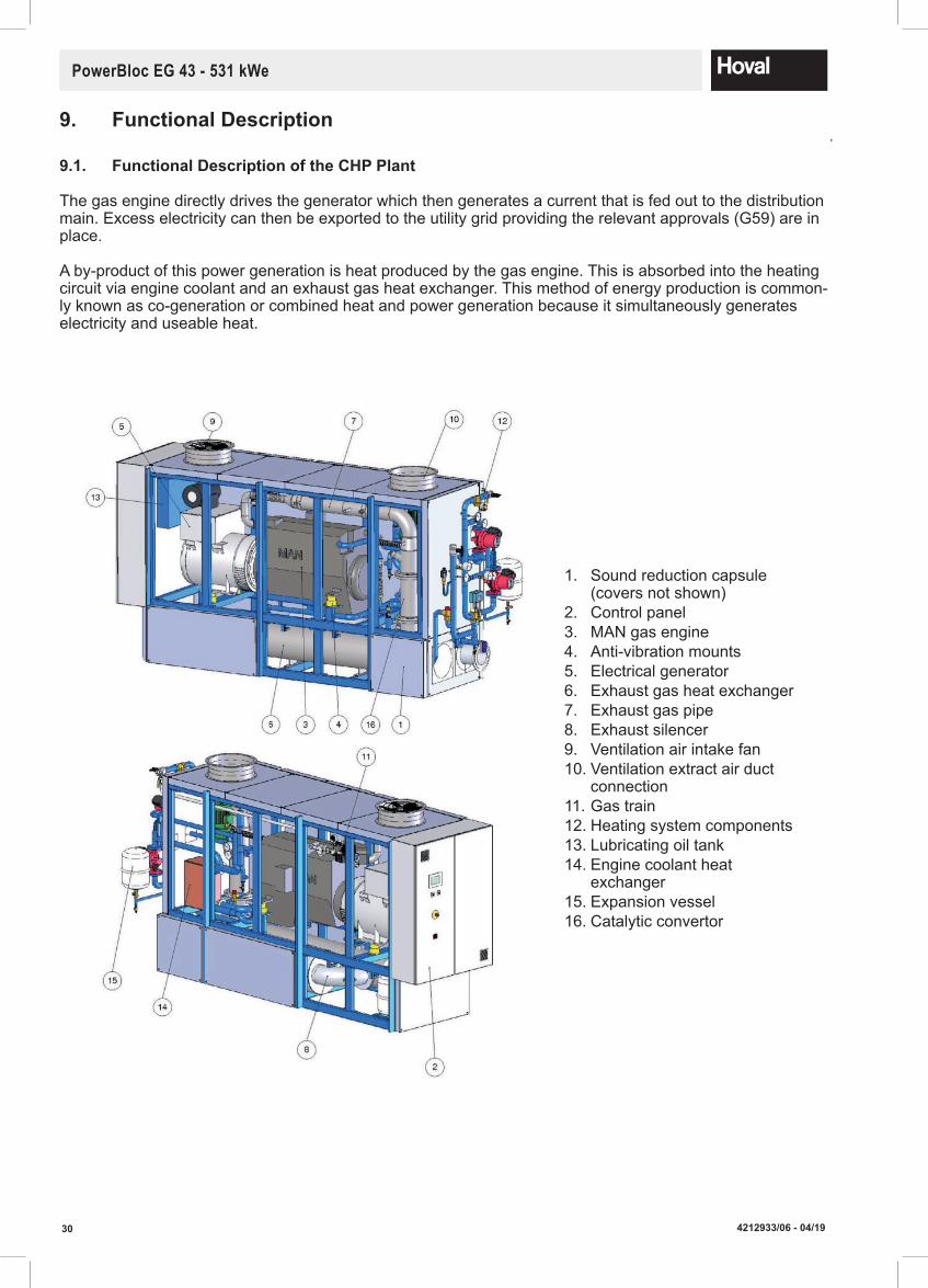
30 4212933/06 - 04/19
PowerBloc EG 43 - 531 kWe
9.1. FunctionalDescriptionoftheCHPPlant
The gas engine directly drives the generator which then generates a current that is fed out to the distribution main. Excess electricity can then be exported to the utility grid providing the relevant approvals (G59) are in place.
A by-product of this power generation is heat produced by the gas engine. This is absorbed into the heating circuit via engine coolant and an exhaust gas heat exchanger. This method of energy production is common-ly known as co-generation or combined heat and power generation because it simultaneously generates electricity and useable heat.
9. FunctionalDescription
1. Sound reduction capsule (covers not shown)
2. Control panel3. MAN gas engine4. Anti-vibration mounts5. Electrical generator6. Exhaust gas heat exchanger7. Exhaust gas pipe8. Exhaust silencer9. Ventilation air intake fan10. Ventilation extract air duct
connection11. Gas train12. Heating system components13. Lubricating oil tank14. Engine coolant heat
exchanger15. Expansion vessel16. Catalytic convertor
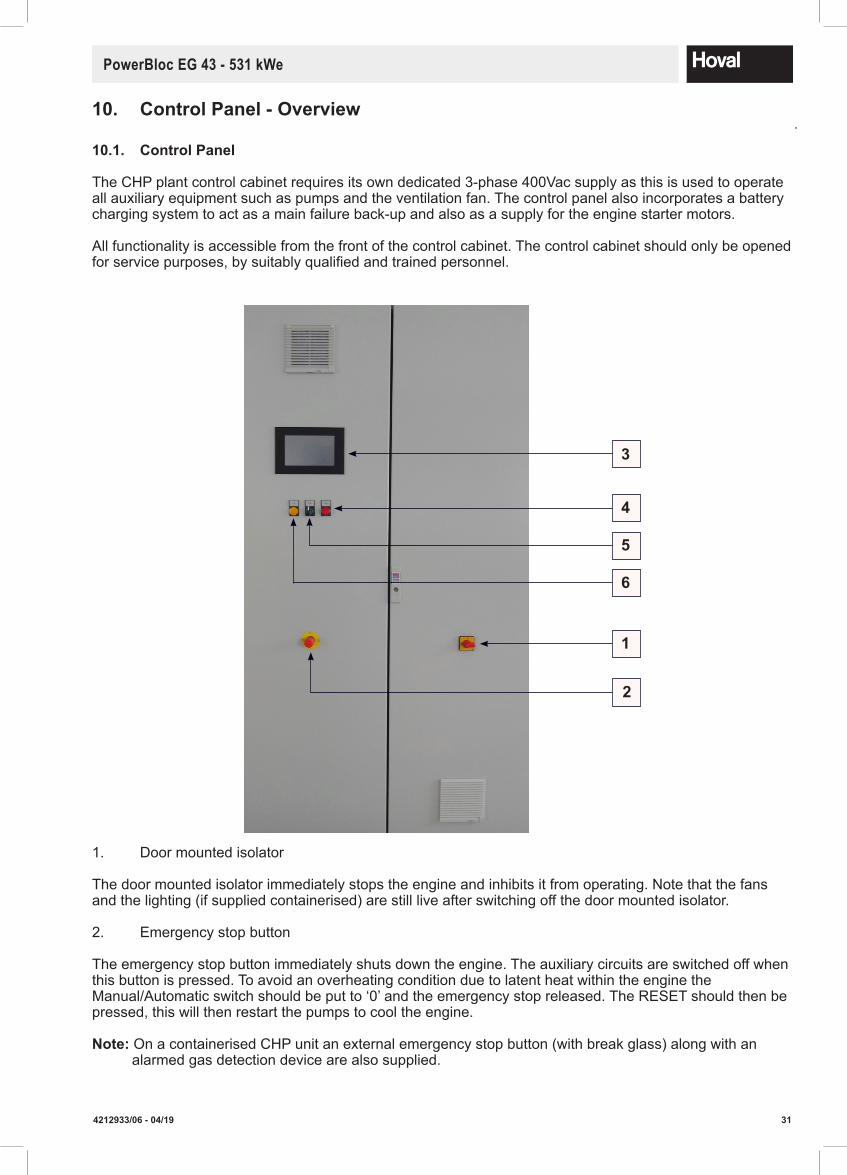
314212933/06 - 04/19
PowerBloc EG 43 - 531 kWe
10.1. Control Panel
The CHP plant control cabinet requires its own dedicated 3-phase 400Vac supply as this is used to operate all auxiliary equipment such as pumps and the ventilation fan. The control panel also incorporates a battery charging system to act as a main failure back-up and also as a supply for the engine starter motors.
All functionality is accessible from the front of the control cabinet. The control cabinet should only be opened for service purposes, by suitably qualified and trained personnel.
1. Door mounted isolator
The door mounted isolator immediately stops the engine and inhibits it from operating. Note that the fans and the lighting (if supplied containerised) are still live after switching off the door mounted isolator.
2. Emergency stop button
The emergency stop button immediately shuts down the engine. The auxiliary circuits are switched off when this button is pressed. To avoid an overheating condition due to latent heat within the engine the Manual/Automatic switch should be put to ‘0’ and the emergency stop released. The RESET should then be pressed, this will then restart the pumps to cool the engine.
Note:On a containerised CHP unit an external emergency stop button (with break glass) along with an alarmed gas detection device are also supplied.
10. Control Panel - Overview
2
6
5
4
3
1

32 4212933/06 - 04/19
PowerBloc EG 43 - 531 kWe
3. 7" graphic touch display
The main control functionality of the CHP plant is accessed using the touch screen controller. This will display all operating conditions and allow the adjustment of parameters providing the correct service codes have been input.
4. Red RESET/Fault illuminated pushbutton
The red light will illuminate when the CHP plant is in a fault condition. A detailed description of the fault is available on the touch screen controller in the alarm menu. If the fault condition has cleared then this button can then be pressed for 3 seconds to clear the fault.
5. M-0-A illuminated selector switch (Manual – Off – Automatic)
When illuminated, this indicates that the CHP plant is running. The selector switch has three positions:• Manual: The CHP plant will start up and control to the set-point set on the display.• Off: The CHP plant will be in an "off" condition.• Automatic: The CHP plant will control dependant on the signals received from the Building Management System.
6. Yellow warning indicator lamp
The yellow lamp will illuminate when the CHP plant is in a warning condition. The warning condition will not stop the machine. If the minor problem is not rectified and worsens this will then develop into a fault. A detailed description of the warning is available on the touch screen controller in the alarm menu.
10.2. Overview of Functionality
All of the control processes for efficient and safe operation are carried out by the controller within the CHP plant control cabinet. Below is a brief overview of these main functions:
• Manual and automatic operation• Complete CHP safety system with warning messages and self protection• Mains and generator monitoring• Automatic engine starter• Electronic speed control for the rotating assembly• Synchronisation, frequency and power output control• Electrical output control• Flow temperature control• Mains back-up operation (optional)• Remote diagnosis and interrogation available• Operating hours, service hours, start and kWh counter.
10.3. ManualandAutomaticOperation
The operating mode is selected with the mode selector switch on the control cabinet door. This switch has three positions, Manual - Off - Automatic.
Manual mode is available to operate the CHP plant on site without the need for a Building Management System. This will then automatically control to a set-point on the touch screen.
Automatic mode allows the CHP plant to respond to an external start/stop signal as well as an analogue control signal to adjust the set-point for site requirements.
When the switch is positioned to ‘0’ the unit will perform a safe shut-down and then stop.
334212933/06 - 04/19
PowerBloc EG 43 - 531 kWe
10.4. SafetySystem
The CHP plant contains its own safety protection to ensure the correct running of the equipment. There are two tiers of safety within the CHP controls, firstly the warnings and secondly the faults. There are multiple information points measured: engine speed, water pressure, mixture pressure, water temperature, oil temperature, exhaust temperature, battery voltage, and oil level.
10.5. GridMonitoring
The CHP plant controller has a function where it monitors the electricity from the national grid. In the event of a fault it will disconnect from the national grid in approximately 100ms. The following signals are monitored: Overvoltage/undervoltage, over-frequency/under-frequency and vector surge.
10.6. GeneratorMonitoring
The CHP plant controller also monitors the generator in the same way as it monitors the electricity from the national grid. The following electrical signals are monitored: Overvoltage/undervoltage, over-frequency/under-frequency, over-current, reverse power and differential current.
10.7. EngineControl
The touch-screen controller operates the engine and has the following control: Safe start and shutdown, starter and ignition, control of both gas valves, control of auxiliary equipment, speed control, engine over-run control and gas leak detection.
10.8. Speed Control
The CHP plant controller has a speed regulator to control the engine between 1440 and 1560 rpm. This controller will ramp the engine up to this speed on start-up and down from this speed when it is in its cool-down cycle. When the generator is synchronised this speed is maintained by the frequency from the grid.
10.9. Power Output Control
When the CHP plant is synchronised the control is switched from speed control to power set-point control. In automatic mode this set-point is derived from the building management system controls but in manual this set-point is input on the touch screen controller. The safety circuits can interrupt this set-point, for example if a warning signal is apparent the CHP plant will run at the pre-set reduced set-point.
10.10. Lambda Control
In order to respond to minor changes in the gas quality, the exhaust gas is measured with a lambda sensor. This acts to automatically adjust the fuelling to suit the current site conditions.
10.11 TouchScreenDisplay
The display is used as the interface to the CHP, showing all measured values as well as any error or warning messages. All of the operating parameters can be adjusted although the manufacturer’s access code is required to do this.
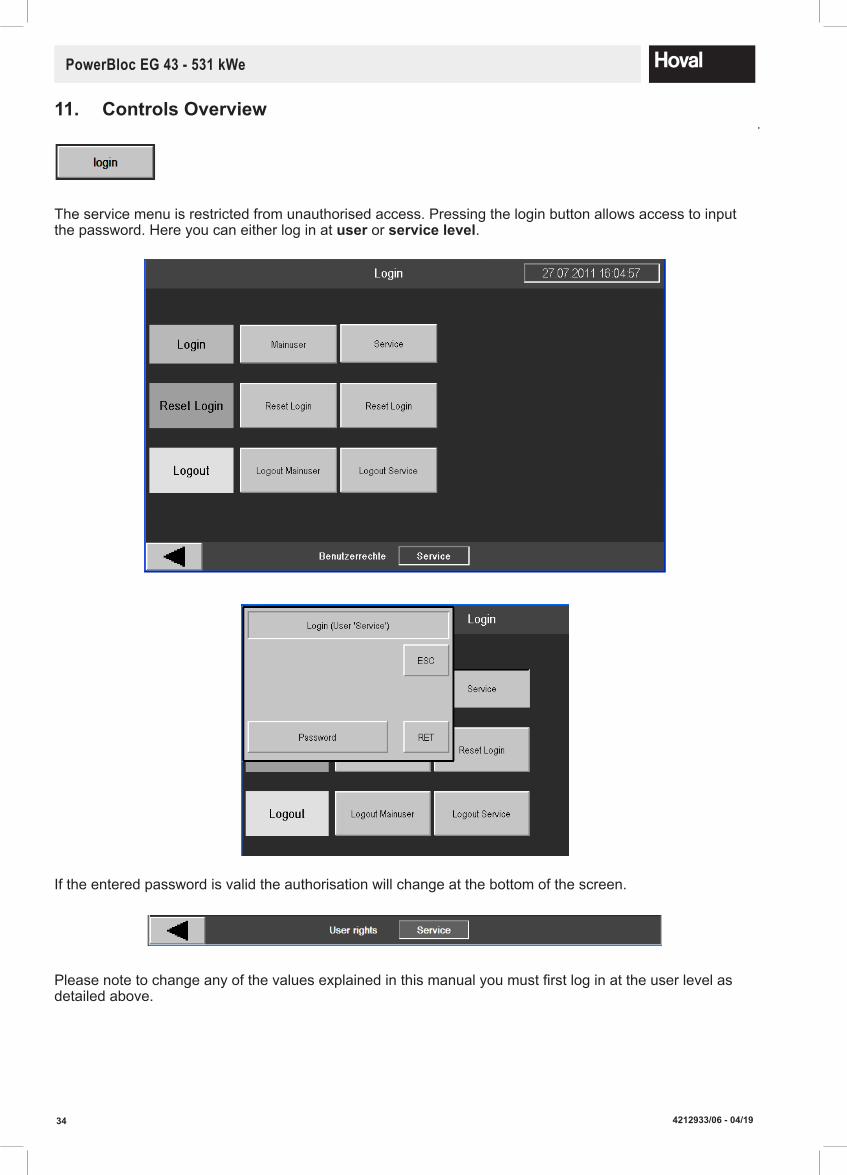
34 4212933/06 - 04/19
PowerBloc EG 43 - 531 kWe
The service menu is restricted from unauthorised access. Pressing the login button allows access to input the password. Here you can either log in at user or servicelevel.
If the entered password is valid the authorisation will change at the bottom of the screen.
Please note to change any of the values explained in this manual you must first log in at the user level as detailed above.
11. ControlsOverview

354212933/06 - 04/19
PowerBloc EG 43 - 531 kWe
Overview of Start Screen
The start screen provides an overview of the CHP outputs and a display of the accumilated running hours with the kWh produced.
The main menu opens by tapping anywhere on the touch screen.
You can go back to the previous page by tapping this arrow button from any other screen.
Mainmenu
To display actual values and operate the CHP controller, the sub-menus, which are described in the follow-ing pages, are accessed by tapping the corresponding touch screen buttons shown in the menu.

36 4212933/06 - 04/19
PowerBloc EG 43 - 531 kWe
This menu item shows an overview of the current status of the CHP plant.
The following set-points can be set for the power output in the top left area (onlytobeadjustedbyCompetentpersonnel):
Set-point for manual mode Set-point for power reduction mode
The signals from the Building Management System are shown in Automatic mode in the bottom right area.
The important engine operating values are displayed in the engine values section.

374212933/06 - 04/19
PowerBloc EG 43 - 531 kWe
The important generator information is displayed on this screen. The active bar graphs on the right show the current outputs of the generator.
The maintenance menu is important for being able to view when the next service is required. Here you also have the button where you can reset the service hours when a service has been performed. Please note, access codes will be required.
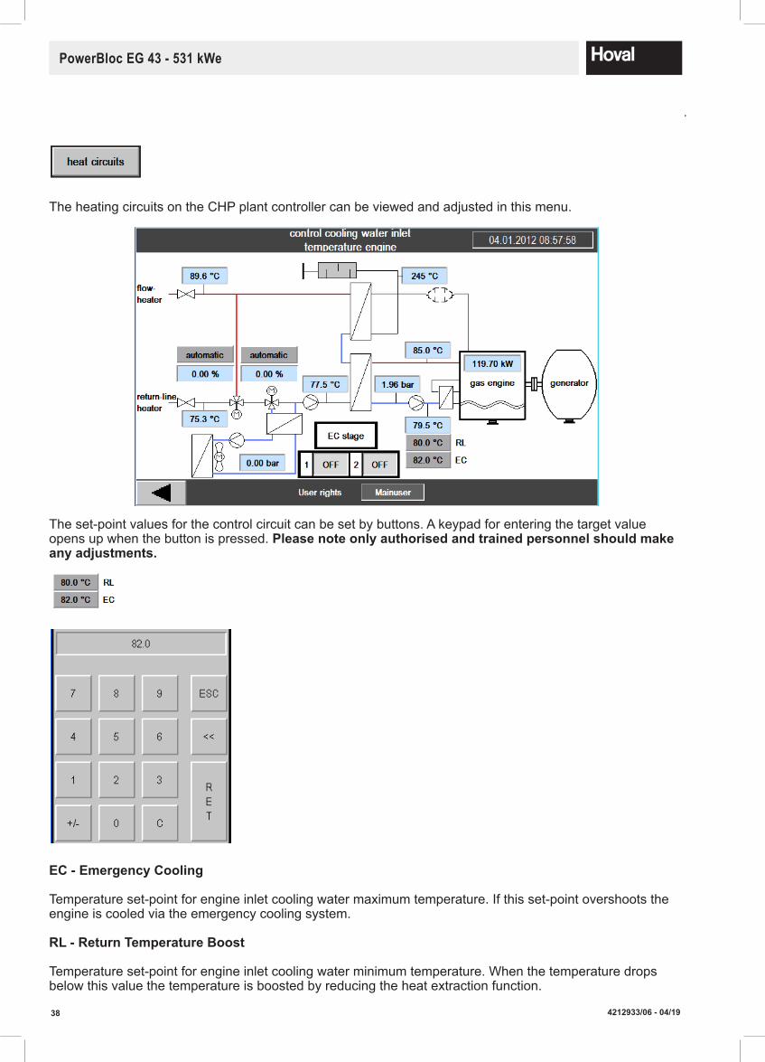
38 4212933/06 - 04/19
PowerBloc EG 43 - 531 kWe
The heating circuits on the CHP plant controller can be viewed and adjusted in this menu.
The set-point values for the control circuit can be set by buttons. A keypad for entering the target value opens up when the button is pressed. Pleasenoteonlyauthorisedandtrainedpersonnelshouldmakeanyadjustments.
EC-EmergencyCooling
Temperature set-point for engine inlet cooling water maximum temperature. If this set-point overshoots the engine is cooled via the emergency cooling system.
RL-ReturnTemperatureBoost
Temperature set-point for engine inlet cooling water minimum temperature. When the temperature drops below this value the temperature is boosted by reducing the heat extraction function.

394212933/06 - 04/19
PowerBloc EG 43 - 531 kWe
The 3-port mixing valves for return temperature control or emergency cooling control can be operated in manual mode for test purposes. This is accessed by the window below when you select manual operation.
When active is selected the valve will display "manual" on the schematic. The set-point for manual mode is entered as a valve position. This is a value from 0-100%. When in manual mode the warning lamp will illumi-nate and a warning message will be displayed in the alarm list.
The lambda value for the engine to control this setting automatically can be set within this menu. It is ad-vised that this is not adjusted unless you are a competent, trained engineer.
For more detailed information regarding the lambda menu please see the Noris Automation controls manual. This menu should only be entered by a competent, trained engineer.
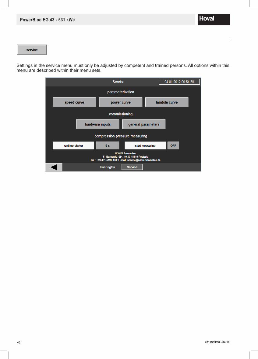
40 4212933/06 - 04/19
PowerBloc EG 43 - 531 kWe
Settings in the service menu must only be adjusted by competent and trained persons. All options within this menu are described within their menu sets.

414212933/06 - 04/19
PowerBloc EG 43 - 531 kWe
12. Pre-Commissioning
12.1 Engine(Hoval will fill the engine with approved engine oil and fit the catalytic converter at commissioning)• Site must have sufficient access for the delivery and removal of the engine oil containers• Only use engine oil as approved by MAN • Fill engine with oil as detailed in the MAN assembly instructions• The oil level should never exceed maximum• The engine must be checked for oil leaks• Catalytic Convertor to hand for fitting after 50-200 run hours, if not already installed
Coolant must be mixed correctly and added to the coolant circuit. This coolant must be of a suitable specification and approved by MAN engines. The coolant circuit must be fully de-aerated.
12.2. Oil Supply(Hoval action at commissioning)• Fill the lubricating oil tank observing all safety and environmental regulations• Check for leaks.
12.3. GasSupply
• Approval must be in place for the use of Natural Gas• Gas purge test and tightness test certificates need to be available prior to commencement of
commissioning• The Natural Gas supply must be installed to the current industry standards.
12.4. HeatingWaterSystem
• The heating water system must have been flushed, filled and de-aerated• The water must be to the quality as specified earlier in this manual• All safety equipment must be operational• Sufficient pressure and flow must be available• Heating load must be available for commissioning.
12.5. Electrical Connection
• A power cable for the CHP plant must be installed for the use of the auxiliary equipment• Cabling must be installed to export electricity• Grid monitoring cabling must be installed to ensure synchronisation is possible• Electrical earthing must be to current standards• The G59/3 application must be in place and certification available• All connections to the Building Management System must be in place• An internet connection must be set-up to allow for remote monitoring• All electrical connections must be tested to the latest relevant standards.
12.6. Static maintenance
If the CHP is not commissioned within 6 months of delivery then the following must happen every 6 months until commissioning:• Remove injection nozzles or spark plugs• Move pistons of cylinders 1 and 6 to bottom dead centre position• Using a pneumatic spray gun, spray 30-40ml diesel fuel + 2% by vol. Auto Desolite K through the injec-
tion nozzles to spark plug bore in cylinders 1 and 6.• Then move pistons of cylinders 2 and 5 to bottom dead centre position and carry out preservation.• Repeat provedure for cylindrs 3 and 4• Briefly turn over engine with starter motor (2 to 3 seconds) or turn engine manually three times.• Re-install spark plugs

42 4212933/06 - 04/19
PowerBloc EG 43 - 531 kWe
12.7.Pre-CommissioningChecklist
Northgate ‐ Newark ‐ Nottinghamshire NG24 1JN – UK Tel: (01636) 672711 ‐ Fax: (01636) 673532 Direct dial: (01636) 593413 e‐mail: [email protected] ‐ Web: www.hoval.co.uk Direct e‐mail: ‐ [email protected]
Rev 2 SC.P 06 Rev 03 ME
2017‐04‐12 Page 1 of 4
Pre-commissioningCombinedHeatandPowerchecklist (All items must be completed and ready for when our engineer arrives on site. If any items on the list are not ready or site conditions dictate we cannot complete, Hoval reserve the right to abort the visit and make a charge for revisiting the site to complete commissioning). Name (person who filled in the this form).
Site Name
Site Address
Post Code.
Site contact
Phone number
E-Mail for reports to be sent,.
Boiler Type Boiler ID No. (1200+6digits):IfKnown
Proposed date of visit. if given:
Company Name of Installer Gas Safe Company number if applicable. (Must be filled in).CHECKLIST Checked Date Sufficient gas available to meet the capacity of all available equipment at full output. Gas line purged, soundness tested and strength tested up to the CHP isolation valve and a copy of the certificate available for the commissioning engineer (In accordance with IGE‐UP‐1). Note the connection must be made with a flexible joint to mitigate vibration on‐site. Natural Gas pressure must be between 18‐100mbar at full output.
Ventilation fitted and installed. This may include ductwork dependant on design. If the extract is ducted then the intake MUST also be ducted. In accordance with IGME/UP/3 &10. The running of the CHP MUST NOT lead to the plant room becoming under a negative condition.
Suitable access available to bring any maintenance parts to the plant. This includes oil and coolant containers.
Heating system connected to the CHP using flexible pipework connections in accordance with a Hoval approved hydraulic schematic.
Heating system water treated to meet the minimum requirements stated in the operation and maintenance manual.
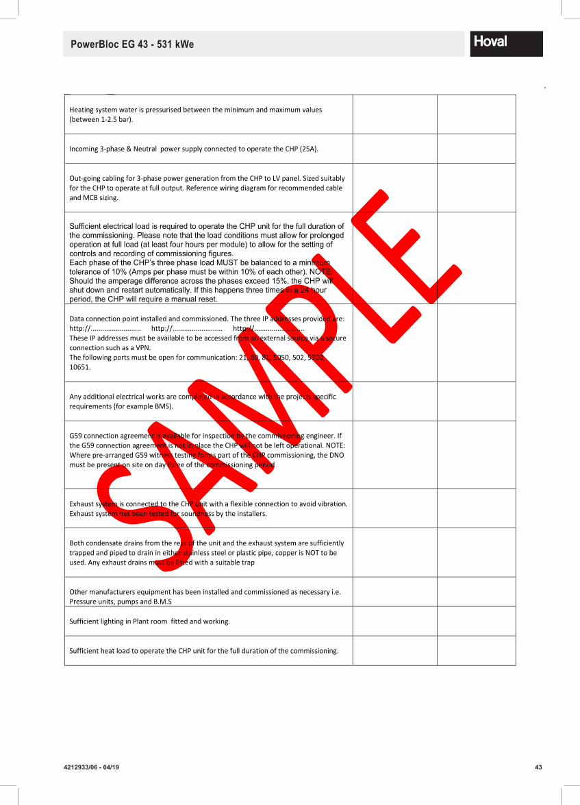
434212933/06 - 04/19
PowerBloc EG 43 - 531 kWe
Northgate ‐ Newark ‐ Nottinghamshire NG24 1JN – UK Tel: (01636) 672711 ‐ Fax: (01636) 673532 Direct dial: (01636) 593413 e‐mail: [email protected] ‐ Web: www.hoval.co.uk Direct e‐mail: ‐ [email protected]
Rev 2 SC.P 06 Rev 03 ME
2017‐04‐12 Page 2 of 4
Heating system water is pressurised between the minimum and maximum values (between 1‐2.5 bar).
Incoming 3‐phase & Neutral power supply connected to operate the CHP (25A).
Out‐going cabling for 3‐phase power generation from the CHP to LV panel. Sized suitably for the CHP to operate at full output. Reference wiring diagram for recommended cable and MCB sizing.
Sufficient electrical load is required to operate the CHP unit for the full duration of the commissioning. Please note that the load conditions must allow for prolonged operation at full load (at least four hours per module) to allow for the setting of controls and recording of commissioning figures. Each phase of the CHP’s three phase load MUST be balanced to a minimum tolerance of 10% (Amps per phase must be within 10% of each other). NOTE: Should the amperage difference across the phases exceed 15%, the CHP will shut down and restart automatically. If this happens three times in a 24 hour period, the CHP will require a manual reset.
Data connection point installed and commissioned. The three IP addresses provided are: http://.......................... http://.......................... http://.......................... These IP addresses must be available to be accessed from an external source via a secure connection such as a VPN. The following ports must be open for communication: 21, 80, 81, 5050, 502, 5900, 10651.
Any additional electrical works are completed in accordance with the projects specific requirements (for example BMS).
G59 connection agreement is available for inspection by the commissioning engineer. If the G59 connection agreement is not in place the CHP will not be left operational. NOTE: Where pre‐arranged G59 witness testing forms part of the CHP commissioning, the DNO must be present on site on day three of the commissioning period
Exhaust system is connected to the CHP unit with a flexible connection to avoid vibration. Exhaust system has been tested for soundness by the installers.
Both condensate drains from the rear of the unit and the exhaust system are sufficiently trapped and piped to drain in either stainless steel or plastic pipe, copper is NOT to be used. Any exhaust drains must be fitted with a suitable trap
Other manufacturers equipment has been installed and commissioned as necessary i.e. Pressure units, pumps and B.M.S
Sufficient lighting in Plant room fitted and working.
Sufficient heat load to operate the CHP unit for the full duration of the commissioning.

44 4212933/06 - 04/19
PowerBloc EG 43 - 531 kWe
Northgate ‐ Newark ‐ Nottinghamshire NG24 1JN – UK Tel: (01636) 672711 ‐ Fax: (01636) 673532 Direct dial: (01636) 593413 e‐mail: [email protected] ‐ Web: www.hoval.co.uk Direct e‐mail: ‐ [email protected]
Rev 2 SC.P 06 Rev 03 ME
2017‐04‐12
Page 3 of 4
The installer Must have all the matrials for commissioning the CHP in the plant room ready to be installed, e.g. Oil , Coolant etc
Spill kit required. Initial fillings for the unit are included upon commissioning. This includes for lubrication oil, engine cooling water, battery acid, corrosion inhibitor and anti-freeze.
Should site rules require the use of a spill kit this should be supplied to site by others prior to the commissioning date.
Please Note:
The engineer will instruct the person(s) responsible for the day to day operation of the CHP as part of the commissioning. If no‐one is available at the time of commissioning the CHPwill be set up and then switched off. Any further visits to site for training will be chargeable.
Hoval Service Engineers when commissioning will check the following:
The CHP is filled with water, coolant, oil and vented. If required the correct safety valve and AAV is fitted
The CHP condensate line is fitted with the correct condensate trap.
An independent pressurized system is operating correctly. Suppliers of the equipment should adjust their equipment during CHP commissioning.
That the CHP, and gas boosters (where fitted), have been wired correctly in accordance to the manufactures wiring instructions. ( a separate enable/0‐10v control with a safety circuit must be installed), all interlocks are functioning.
Correct operation of the gas booster (if fitted). If run and standby units are fitted, the correct non‐return valves are installed correctly All gas boosters are installed with the correct anti‐vibration kits mounts.
The CHP has not been damaged in transit or during installation and that it is a suitable type for the fuel available on site. The nameplate on the burner indicates for which type of fuel it is designed. All damage will be noted. All items packed in transit are removed from the CHP
CHP controls thermostats are adjusted to suit system design flow temperature.
The CHP pressure relief valve setting is suitable for the system (the setting should be 0.7 bar above the system pressure).
PleaseNote:
The engineer will instruct person(s) responsible for the day to day operation of the CHP as part of the com-missioning. If no-one is available at the time of commissioning the CHP will be set up and then switched off.Any further visits to site for training will be chargeable.
Hoval Service Engineers when commissioning will check the following:
The CHP is filled with water, coolant, oil and vented. If required the correct safety valve and AAV is fitted
The CHP condensate line is fitted with the correct condensate trap.
An independent pressurized system is operating correctly. Suppliers of the equipment should adjust theirequipment during CHP commissioning.
That the CHP, and gas boosters (where fitted), have been wired correctly in accordance to the manufactureswiring instructions. (a separate enable/0-10v control with a safety circuit must be installed), all interlocks are functioning.
Correct operation of the gas booster (if fitted). If run and standby units are fitted, the correct non-return valves are installed correctly
All gas boosters are installed with the correct anti-vibration kits mounts.
The CHP has not been damaged in transit or during installation and that it is a suitable type for the fuelavailable on site. The nameplate on the burner indicates for which type of fuel it is designed. All damage will be noted.
All items packed in transit are removed from the CHP.
CHP controls thermostats are adjusted to suit system design flow temperature.
The CHP pressure relief valve setting is suitable for the system (the setting should be 0.7 bar above the system pressure).
The automatic air vent is fitted in the appropriate position.
Oil supply pressure and temperature is suitable.
Commissioning is in accordance with CHP makers requirements.
CHP is adjusted to give optimum combustion.
The heating engineer will have the opportunity to receive instruction on the correct operation of the plantduring Commissioning.
materials

454212933/06 - 04/19
PowerBloc EG 43 - 531 kWe
13.1 Overview
The CHP plant must have its preventative maintenance carried out at the required intervals, as specified in the MAN engine manual. This must be performed and logged to keep the warranty valid. This includes day-to-day operational checks. If a service is missed the warranty is void. All maintenance work on the CHP plant must be performed by a Hoval or Hoval approved Engineer using MAN approved components. Inad-equate or improper maintenance to the CHP plant will cause severe damage that may not be repairable. Hoval accepts no responsibility for any damage caused by a lack of maintenance. For the full service sched-ule please refer to the MAN operating and maintenance manual for the specific engine.
Before commencing any work on the CHP plant all operating values displayed on the touch screen controller must be recorded.
A fault log must be kept to allow for conclusions to be drawn and help diagnose any problems.
The CHP plant must be safely shut down and be locked off from operating to ensure the plant does not operate while it is being worked on.
A permit-to-work system should be put in place by the operator prior to all such work being undertaken.
13.2. OilChange
After the CHP plant has been switched off it should be left to stand for 10 minutes. After this time the oil consumption since the last service can be measured and the engine can be checked for any oil leaks. The oil can then be drained from the bottom of the sump until it is empty of oil, and the oil filters can then be replaced. Once the filters have been re-fitted and the drain valve closed, oil can then be added to the maximum level on the dipstick. Only use oil as specified in the MAN engine manual.
The maximum oil level should not be exceeded. Used oil should always be analysed in accordance with the MAN requirements.
13.3. OilChangeProcedure
The careful management of the oil change intervals is crucial to ensuring engines operate without incident. Oil changes frequency is to be actively managed to ensure that the associated oil analysis reports always show a normal status. Oil changes should be initially carried out evey 300 hours (after the required once only 20-50 hour oil change). Following satisfactory oil analysis reports, this frequency can be increased to 400 hours and so on, but only if the oil reports are consistently normal. In all cases the maximum allowable operating time between service intervals shall be 800 hrs.Every CHP should be programmed to shut down after the agreed service hours for the engine have been reached. Oil samples are to immediately sent to the testing laboratiry so that reports are received back in a few days.All reports are then filed in SAP against the site concerned but also kept in the individual site folders held within the Service Engineer Documents folder.For engines running on biogas, different operating limits will apply but in any case the maximum operating limits will apply, but in any case the maximum operating time between oil changes shall not exceed 400 hours. Again a process of determining the optimal service intervals needs to be carried out.
13.4. Sparkplugs
Depending on the service level performed the spark plugs must be either checked or replaced. When check-ing a spark plug the gap must be checked and adjusted if necessary. They should then be re-fitted to the engine and tightened to a torque of 27 Nm.
13.5. Air Filter
The air filter must be cleaned or replaced depending on the service level. The airbox must be checked to ensure it is making a good seal so that all air entering the engine is passing through the air filter.
13. MaintenanceandServicing
46 4212933/06 - 04/19
PowerBloc EG 43 - 531 kWe
13.6. Valve Clearance
As mechanical tappets are used on the Hoval CHP plant, the valve clearance must be checked as pre-scribed in the maintenance schedule and readjusted if necessary in accordance with the engine manufac-turer's instructions.
13.7. Starter Battery
When the CHP plant has starter motor batteries, they must be checked for any signs of leakage and the level of fluid checked. If they require topping up this must be done with distilled water.
13.8. EngineCoolantPressure
If the coolant pressure in the engine is too low then this must be topped up. The correct ratio of water and antifreeze must be used. The antifreeze used must be to the correct specification as published in the MAN engine manual.
13.9. Generator
The generator electrical connections must be checked and cleaned each visit. Additional to this the genera-tor should require no further maintenance.
13.10. PostService
Upon completion of the service the maintenance hours must be reset on the touch screen controller. After a service, the service checklist must be completed and the CHP plant must be put back into automatic operation and restarted.
Importantnote:The above are for guidance only and the full servicing requirements are detailed in the MAN operations and maintenance manual for the specific engine.
13.11. Day-to-day operation
It is imperative that there is a suitable person on site that is able to do day-to-day checks on the CHP and visual inspections. Key points here are to visually check for any oil or coolant leaks, check for any unfamiliar noises and also check for any unfamiliar vibrations. It is also important this person has a basic understand-ing of the controller so that they can interpret error messages accordingly if required.
13.12Maximumwearvalues
Properties Requirements TestMethodsViscosity at 40°C max. +15 / -10% of fresh oil value DIN 51562-1Viscosity at 100°C no change of viscosity class DIN 51562-1Total base number (TBN) mg KOH/g min. 3 DIN ISO 3771 Total acid number (TAN) mg KOH/g increase max. +2.5 ASTM D 664pH value min. 4 Water % max. 0.1 EN ISO 12 9371,2-Ethandiole % max. 0.1 DIN 51375-1Oxidation at 5.8 µm A/cm max.20 DIN 51453 Nitration at 6.1 µm A/cm max 20 DIN 51453Wear elementsIron mg/kg max. 15/1000h** ICPCopper* mg/kg max. 10/1000h** DIN 51399-1 /Lead mg/kg max. 10/1000h** RFATin mg/kg max. 5/1000h** E DIN 51399-2Aluminium mg/kg max. 10/1000h**Chromium mg/kg max. 10/1000h**Silicium mg/kg max. 10/1000h**Sodium mg/kg fresh oil
* Copper content can be higher during the first 2000 operating hours.** Operating hours
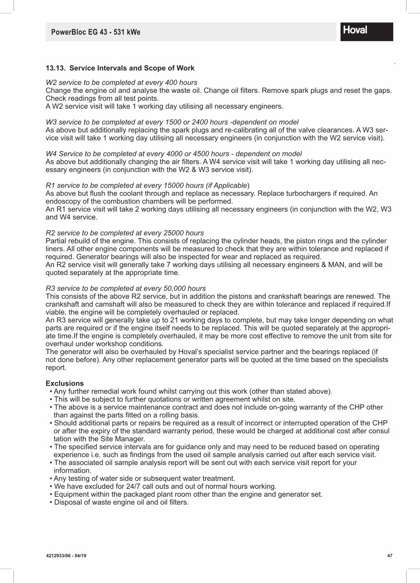
474212933/06 - 04/19
PowerBloc EG 43 - 531 kWe
W2 service to be completed at every 400 hoursChange the engine oil and analyse the waste oil. Change oil filters. Remove spark plugs and reset the gaps. Check readings from all test points.A W2 service visit will take 1 working day utilising all necessary engineers.
W3 service to be completed at every 1500 or 2400 hours -dependent on modelAs above but additionally replacing the spark plugs and re-calibrating all of the valve clearances. A W3 ser-vice visit will take 1 working day utilising all necessary engineers (in conjunction with the W2 service visit).
W4 Service to be completed at every 4000 or 4500 hours - dependent on modelAs above but additionally changing the air filters. A W4 service visit will take 1 working day utilising all nec-essary engineers (in conjunction with the W2 & W3 service visit).
R1 service to be completed at every 15000 hours (if Applicable)As above but flush the coolant through and replace as necessary. Replace turbochargers if required. An endoscopy of the combustion chambers will be performed.An R1 service visit will take 2 working days utilising all necessary engineers (in conjunction with the W2, W3 and W4 service.
R2 service to be completed at every 25000 hours Partial rebuild of the engine. This consists of replacing the cylinder heads, the piston rings and the cylinder liners. All other engine components will be measured to check that they are within tolerance and replaced if required. Generator bearings will also be inspected for wear and replaced as required.An R2 service visit will generally take 7 working days utilising all necessary engineers & MAN, and will be quoted separately at the appropriate time.
R3 service to be completed at every 50,000 hours This consists of the above R2 service, but in addition the pistons and crankshaft bearings are renewed. The crankshaft and camshaft will also be measured to check they are within tolerance and replaced if required.If viable, the engine will be completely overhauled or replaced.An R3 service will generally take up to 21 working days to complete, but may take longer depending on what parts are required or if the engine itself needs to be replaced. This will be quoted separately at the appropri-ate time.If the engine is completely overhauled, it may be more cost effective to remove the unit from site for overhaul under workshop conditions.The generator will also be overhauled by Hoval’s specialist service partner and the bearings replaced (if not done before). Any other replacement generator parts will be quoted at the time based on the specialists report.
Exclusions • Any further remedial work found whilst carrying out this work (other than stated above). • This will be subject to further quotations or written agreement whilst on site. • The above is a service maintenance contract and does not include on-going warranty of the CHP other than against the parts fitted on a rolling basis. • Should additional parts or repairs be required as a result of incorrect or interrupted operation of the CHP or after the expiry of the standard warranty period, these would be charged at additional cost after consul tation with the Site Manager. • The specified service intervals are for guidance only and may need to be reduced based on operating experience i.e. such as findings from the used oil sample analysis carried out after each service visit. • The associated oil sample analysis report will be sent out with each service visit report for your information. • Any testing of water side or subsequent water treatment. • We have excluded for 24/7 call outs and out of normal hours working. • Equipment within the packaged plant room other than the engine and generator set. • Disposal of waste engine oil and oil filters.
13.13. ServiceIntervalsandScopeofWork

48 4212933/06 - 04/19
PowerBloc EG 43 - 531 kWe
13.14. MaintenanceSchedule-EG43
April 2017
Maintenanceschedule E0834 E312 By operatoracc.tocommissioning,R2,R3,R1/LEengine
only
Corresp.oilanalysis At approx. At approx. At approx. At approx. At approx.
daily 20-50 no info * 1'600 4'800 15'000 30'000 60'000
M1 M2 M3 M4 R1 R2 R3
T T T T T T T T
T T T T T T T T
T T T T T T T T
T T T T T T T T
T T T T T T T T
T T T T T T T T
0 M1 M2 M2 M2 M2 M2 M2
0 M1 M2 M2 M2 M2 M2 M2
0 M1 M2 M2 M2 M2 M2 M2
0 0 M2 M2 M2 M2 M2 M2
0 0 M2 0 0 0 0 0
0 M1 M3 M3 M3 M3 M3 M3
0 M1 M3 M3 M3 M3 M3 M3
0 M1 M3 M3 M3 M3 M3 M3
0 M1 M3 M3 M3 M3 M3 M3
0 0 M3 M3 M3 M3 M3 M3
0 0 M3 M3 M3 M3 M3 M3
0 0 M3 M3 M3 M3 M3 M3
0 0 M3 M3 M3 M3 M3 M3
0 0 M3 M3 M3 M3 M3 M3
0 M1 M3 M3 M3 M3 M3 M3
0 0 M4 M4 M4 M4 M4 M4
R2 R2 R2 R2 R2 R2
0 0 R1 R1 R1 R1 R1 R1
0 0 0 0 0 0 0 0
0 0 0 0 0 0 0 0
0 0 0 0 0 0 0 0
0 0 0 0 0 0 0 0
0 0 0 0 0 0 0 0
0 0 R2 R2 R2 R2 R2 R2
0 0 R2 R2 R2 R2 R2 R2
0 0 R2 R2 R2 R2 R2 R2
0 0 R2 R2 R2 R2 R2 R2
0 0 R2 R2 R2 R2 R2 R2
0 0 R2 R2 R2 R2 R2 R2
0 0 R3 R3 R3 R3 R3 R3
0 0 R3 R3 R3 R3 R3 R3
0 0 R3 R3 R3 R3 R3 R3
0 M1 M3 M3 M3 M3 M3 M3
0 0 R1 R1 R1 R1 R1 R1
0 M1 M3 M3 M3 M3 M3 M3
0 0 M3 M3 M3 M3 M3 M3
0 0 M3 M3 M3 M3 M3 M3
0 0 M3 M3 M3 M3 M3 M3
0 0 M3 M3 M3 M3 M3 M3
0 M1 0 0 0 0 0 0
0 M1 M3 M3 M3 M3 M3 M3
0 0 M3 M3 M3 M3 M3 M3
0 M1 M4 M4 M4 M4 M4 M4
0 0 M4 M4 M4 M4 M4 M4
0 M1 M3 M3 M3 M3 M3 M3
0 M1 M3 M3 M3 M3 M3 M3
0 0 R2 R2 R2 R2 R2 R2
0 M1 M3 M3 M3 M3 M3 M3
0 0 M4 M4 M4 M4 M4 M4
0 0 M4 M4 M4 M4 M4 M4
0 0 M3 M3 M3 M3 M3 M3
0 0 M3 M3 M3 M3 M3 M3
0 0 R2 R2 R2 R2 R2 R2
0 0 R2 R2 R2 R2 R2 R2
0 0 M3 M3 M3 M3 M3 M3
0 0 M3 M3 M3 M3 M3 M3
0 0 M3 M3 M3 M3 M3 M3
Date Signature
Check exchanger system, clean or replace if necessary
Check starter batteries / top up distilled water
Check generator bearings for damage and loss of lubricantLubricate generator (Marelli) according to manufacturer's instructions
Check generator bearings and replace if necessaryCheck cables and pipes, control panel connection terminals for damage and retighten if necessaryCheck/calibrate sensorsCheck indicator lights and control functions
Check control panel air filter, replace if necessaryCheck and, if necessary, replace lambda probe
Check rpm pick-up and clean if necessaryElectrical system
Check compressor lubricator and replace if necessary
Check cubicle fan, intake duct air filter, replace filter if necessary
Clean exhaust gas heat exchanger if necessary
Check flue gas system for tightness, tighten screw connections if necessary
Check flue gas heat exchanger flange connections and seals; replace seals if necessary
Remove condensate from flue gas system
Check flue gas system for external contaminationExhaustgas system
Check function of pumps, valves and safety valves
Check anticorrosive and frost protection concentration
Check steel-mesh hoses, armoured tubes and radiator hoses and replace if necessary
Change anticorrosion and frost protection agent
Check controlled gas system for tightness, clean gas mixer if necessary
Major engine overhaul
Check pistons, replace if necessaryReplace cylinder heads
Replace big end bearings
Replace crankshaft bearings if necessaryMeasure crankshaft and camshaft
Replace piston rings
Replace spark plugs
Check and log compression pressure
Check oil separator and clean if necessary
Check ignition cables and spark plug sockets and replace if necessary
Replace bushings
Check starter function, clean
Check and log ignition timing
Measure and log crankcase pressure
Check valve clearance and adjust and log if necessary
Measure crankshaft play, axial end play
Combustion chamber endoscopy
Replace flue gas turbocharger if necessaryCheck flue gas pipe blade rings
Check, clean flue gas turbocharger
Maintenance performed:
Maintenance interval in operating hours
Maintenance and repair levels
Test and functional check runCheck and log operating dataCheck oil level in engine and day tankCheck and log cooling water and system pressureCheck seal and retighten screw and hose connections if necessaryCheck engine for stability and running noises
Measure / log negative intake pressureCheck / calibrate spark plugs
Check gas filter, clean or replace if necessary
TheengineoillifetimesmustbedeterminedonthebasisofregularoilanalysesinaccordancewithMANstandardM3271-2fornaturalgasandM3271-4forspecialgas.
*MaintenanceM2mustbecarriedoutdependingontheoilanalysis(dependingonmax.800hifusingpartially/fullysyntheticoil).Gradualincreaseofoilservicelivespossiblethroughoilanalysis(inincrementsof100hmax.).
Incaseswherethecompositionofgasfluctuates,regularoilanalysesmustbecarriedout.InthecaseofR1,R2andR3revisionwork,theintervalsaresimplyforecastsandarenotbinding,eachissubjecttocompliancewiththegasqualityforMANindustrialgasenginesandoperationoftheenginesinaccordancewiththeexhaustlimitvaluesdefinedinTA-Luft.Thismaintenanceschedulecoversstandardmaintenancetasks.Pleasetakeaccountofanyspecial,project-specificconsiderations.
Engine
Log oil analysis and oil consumption
Change engine oil and engine oil filter
Cooling circuits
Replace rubber coupling
Replace loading mixture hose
Measure and log flue gas back pressure including catalystCheck and log emissions
Check connecting rods and replace if necessary
Check / calibrate throttle valve
Check mixture cooler and clean if necessary
Check flue gas collector engine and replace if necessary
Mixture preparation
CHP plant module EG-43

494212933/06 - 04/19
PowerBloc EG 43 - 531 kWe
April 2017
Maintenanceschedule E0834 E302 By operatoracc.tocommissioning,R2,R3,R1/LEengine
only
Corresp.oilanalysis At approx. At approx. At approx. At approx. At approx.
daily 20-50 no info * 1'600 4'800 15'000 30'000 60'000
M1 M2 M3 M4 R1 R2 R3
T T T T T T T T
T T T T T T T T
T T T T T T T T
T T T T T T T T
T T T T T T T T
T T T T T T T T
0 M1 M2 M2 M2 M2 M2 M2
0 M1 M2 M2 M2 M2 M2 M2
0 M1 M2 M2 M2 M2 M2 M2
0 0 M2 M2 M2 M2 M2 M2
0 0 M2 0 0 0 0 0
0 M1 M3 M3 M3 M3 M3 M3
0 M1 M3 M3 M3 M3 M3 M3
0 M1 M3 M3 M3 M3 M3 M3
0 M1 M3 M3 M3 M3 M3 M3
0 0 M3 M3 M3 M3 M3 M3
0 0 M3 M3 M3 M3 M3 M3
0 0 M3 M3 M3 M3 M3 M3
0 0 M3 M3 M3 M3 M3 M3
0 0 M3 M3 M3 M3 M3 M3
0 M1 M3 M3 M3 M3 M3 M3
0 0 M4 M4 M4 M4 M4 M4
R2 R2 R2 R2 R2 R2
0 0 R1 R1 R1 R1 R1 R1
0 0 0 0 0 0 0 0
0 0 0 0 0 0 0 0
0 0 0 0 0 0 0 0
0 0 0 0 0 0 0 0
0 0 0 0 0 0 0 0
0 0 R2 R2 R2 R2 R2 R2
0 0 R2 R2 R2 R2 R2 R2
0 0 R2 R2 R2 R2 R2 R2
0 0 R2 R2 R2 R2 R2 R2
0 0 R2 R2 R2 R2 R2 R2
0 0 R2 R2 R2 R2 R2 R2
0 0 R3 R3 R3 R3 R3 R3
0 0 R3 R3 R3 R3 R3 R3
0 0 R3 R3 R3 R3 R3 R3
0 M1 M3 M3 M3 M3 M3 M3
0 0 R1 R1 R1 R1 R1 R1
0 M1 M3 M3 M3 M3 M3 M3
0 0 M3 M3 M3 M3 M3 M3
0 0 M3 M3 M3 M3 M3 M3
0 0 M3 M3 M3 M3 M3 M3
0 0 M3 M3 M3 M3 M3 M3
0 M1 0 0 0 0 0 0
0 M1 M3 M3 M3 M3 M3 M3
0 0 M3 M3 M3 M3 M3 M3
0 M1 M4 M4 M4 M4 M4 M4
0 0 M4 M4 M4 M4 M4 M4
0 M1 M3 M3 M3 M3 M3 M3
0 M1 M3 M3 M3 M3 M3 M3
0 0 R2 R2 R2 R2 R2 R2
0 M1 M3 M3 M3 M3 M3 M3
0 0 M4 M4 M4 M4 M4 M4
0 0 M4 M4 M4 M4 M4 M4
0 0 M3 M3 M3 M3 M3 M3
0 0 M3 M3 M3 M3 M3 M3
0 0 R2 R2 R2 R2 R2 R2
0 0 R2 R2 R2 R2 R2 R2
0 0 M3 M3 M3 M3 M3 M3
0 0 M3 M3 M3 M3 M3 M3
0 0 M3 M3 M3 M3 M3 M3
Date Signature
Incaseswherethecompositionofgasfluctuates,regularoilanalysesmustbecarriedout.InthecaseofR1,R2andR3revisionwork,theintervalsaresimplyforecastsandarenotbinding,eachissubjecttocompliancewiththegasqualityforMANindustrialgasenginesandoperationoftheenginesinaccordancewiththeexhaustlimitvaluesdefinedinTA-Luft.Thismaintenanceschedulecoversstandardmaintenancetasks.Pleasetakeaccountofanyspecial,project-specificconsiderations.
Log oil analysis and oil consumption
Change engine oil and engine oil filter
Replace rubber coupling
Replace loading mixture hose
Measure and log flue gas back pressure including catalystCheck and log emissions
Check connecting rods and replace if necessary
Check / calibrate throttle valve
Check mixture cooler and clean if necessary
Check flue gas collector engine and replace if necessary
Maintenance performed:
Maintenance interval in operating hours
Maintenance and repair levels
Test and functional check runCheck and log operating dataCheck oil level in engine and day tankCheck and log cooling water and system pressureCheck seal and retighten screw and hose connections if necessaryCheck engine for stability and running noises
Measure / log negative intake pressureCheck / calibrate spark plugs
Check gas filter, clean or replace if necessary
TheengineoillifetimesmustbedeterminedonthebasisofregularoilanalysesinaccordancewithMANstandardM3271-2fornaturalgasandM3271-4forspecialgas.
*MaintenanceM2mustbecarriedoutdependingontheoilanalysis(dependingonmax.800hifusingpartially/fullysyntheticoil).Gradualincreaseofoilservicelivespossiblethroughoilanalysis(inincrementsof100hmax.).
Replace spark plugs
Check and log compression pressure
Check oil separator and clean if necessary
Check ignition cables and spark plug sockets and replace if necessary
Replace bushings
Check starter function, clean
Check and log ignition timing
Measure and log crankcase pressure
Check valve clearance and adjust and log if necessary
Measure crankshaft play, axial end play
Combustion chamber endoscopy
Replace flue gas turbocharger if necessaryCheck flue gas pipe blade rings
Check, clean flue gas turbocharger
Major engine overhaul
Check pistons, replace if necessaryReplace cylinder heads
Replace big end bearings
Replace crankshaft bearings if necessaryMeasure crankshaft and camshaft
Replace piston rings
Check function of pumps, valves and safety valves
Check anticorrosive and frost protection concentration
Check steel-mesh hoses, armoured tubes and radiator hoses and replace if necessary
Change anticorrosion and frost protection agent
Check controlled gas system for tightness, clean gas mixer if necessaryCheck compressor lubricator and replace if necessary
Check cubicle fan, intake duct air filter, replace filter if necessary
Clean exhaust gas heat exchanger if necessary
Check flue gas system for tightness, tighten screw connections if necessary
Check flue gas heat exchanger flange connections and seals; replace seals if necessary
Remove condensate from flue gas system
Check flue gas system for external contamination
Check exchanger system, clean or replace if necessary
Check starter batteries / top up distilled water
Check generator bearings for damage and loss of lubricantLubricate generator (Marelli) according to manufacturer's instructions
Check generator bearings and replace if necessaryCheck cables and pipes, control panel connection terminals for damage and retighten if necessaryCheck/calibrate sensorsCheck indicator lights and control functions
Check control panel air filter, replace if necessaryCheck and, if necessary, replace lambda probe
Check rpm pick-up and clean if necessary
Electricalsystem
CHP plant module EG-50
Electrical system
Exhaust gas system
Engine
Cooling circuits
Mixture preparation
13.15. MaintenanceSchedule-EG50

50 4212933/06 - 04/19
PowerBloc EG 43 - 531 kWe
13.16. MaintenanceSchedule-EG70
April 2017
Maintenanceschedule E0836 E302 By operatoracc.tocommissioning,R2,R3,R1/LEengine
only
Corresp.oilanalysis At approx. At approx. At approx. At approx. At approx.
daily 20-50 no info * 1'600 4'800 15'000 30'000 60'000
M1 M2 M3 M4 R1 R2 R3
T T T T T T T T
T T T T T T T T
T T T T T T T T
T T T T T T T T
T T T T T T T T
T T T T T T T T
0 M1 M2 M2 M2 M2 M2 M2
0 M1 M2 M2 M2 M2 M2 M2
0 M1 M2 M2 M2 M2 M2 M2
0 0 M2 M2 M2 M2 M2 M2
0 0 M2 0 0 0 0 0
0 M1 M3 M3 M3 M3 M3 M3
0 M1 M3 M3 M3 M3 M3 M3
0 M1 M3 M3 M3 M3 M3 M3
0 M1 M3 M3 M3 M3 M3 M3
0 0 M3 M3 M3 M3 M3 M3
0 0 M3 M3 M3 M3 M3 M3
0 0 M3 M3 M3 M3 M3 M3
0 0 M3 M3 M3 M3 M3 M3
0 0 M3 M3 M3 M3 M3 M3
0 M1 M3 M3 M3 M3 M3 M3
0 0 M4 M4 M4 M4 M4 M4
R2 R2 R2 R2 R2 R2
0 0 R1 R1 R1 R1 R1 R1
0 0 0 0 0 0 0 0
0 0 0 0 0 0 0 0
0 0 0 0 0 0 0 0
0 0 0 0 0 0 0 0
0 0 0 0 0 0 0 0
0 0 R2 R2 R2 R2 R2 R2
0 0 R2 R2 R2 R2 R2 R2
0 0 R2 R2 R2 R2 R2 R2
0 0 R2 R2 R2 R2 R2 R2
0 0 R2 R2 R2 R2 R2 R2
0 0 R2 R2 R2 R2 R2 R2
0 0 R3 R3 R3 R3 R3 R3
0 0 R3 R3 R3 R3 R3 R3
0 0 R3 R3 R3 R3 R3 R3
0 M1 M3 M3 M3 M3 M3 M3
0 0 R1 R1 R1 R1 R1 R1
0 M1 M3 M3 M3 M3 M3 M3
0 0 M3 M3 M3 M3 M3 M3
0 0 M3 M3 M3 M3 M3 M3
0 0 M3 M3 M3 M3 M3 M3
0 0 M3 M3 M3 M3 M3 M3
0 M1 0 0 0 0 0 0
0 M1 M3 M3 M3 M3 M3 M3
0 0 M3 M3 M3 M3 M3 M3
0 M1 M4 M4 M4 M4 M4 M4
0 0 M4 M4 M4 M4 M4 M4
0 M1 M3 M3 M3 M3 M3 M3
0 M1 M3 M3 M3 M3 M3 M3
0 0 R2 R2 R2 R2 R2 R2
0 M1 M3 M3 M3 M3 M3 M3
0 0 M4 M4 M4 M4 M4 M4
0 0 M4 M4 M4 M4 M4 M4
0 0 M3 M3 M3 M3 M3 M3
0 0 M3 M3 M3 M3 M3 M3
0 0 R2 R2 R2 R2 R2 R2
0 0 R2 R2 R2 R2 R2 R2
0 0 M3 M3 M3 M3 M3 M3
0 0 M3 M3 M3 M3 M3 M3
0 0 M3 M3 M3 M3 M3 M3
Date Signature
Incaseswherethecompositionofgasfluctuates,regularoilanalysesmustbecarriedout.InthecaseofR1,R2andR3revisionwork,theintervalsaresimplyforecastsandarenotbinding,eachissubjecttocompliancewiththegasqualityforMANindustrialgasenginesandoperationoftheenginesinaccordancewiththeexhaustlimitvaluesdefinedinTA-Luft.Thismaintenanceschedulecoversstandardmaintenancetasks.Pleasetakeaccountofanyspecial,project-specificconsiderations.
Log oil analysis and oil consumption
Change engine oil and engine oil filter
Replace rubber coupling
Replace loading mixture hose
Measure and log flue gas back pressure including catalystCheck and log emissions
Check connecting rods and replace if necessary
Check / calibrate throttle valve
Check mixture cooler and clean if necessary
Check flue gas collector engine and replace if necessary
Maintenance performed:
Maintenance interval in operating hours
Maintenance and repair levels
Test and functional check runCheck and log operating dataCheck oil level in engine and day tankCheck and log cooling water and system pressureCheck seal and retighten screw and hose connections if necessaryCheck engine for stability and running noises
Measure / log negative intake pressureCheck / calibrate spark plugs
Check gas filter, clean or replace if necessary
TheengineoillifetimesmustbedeterminedonthebasisofregularoilanalysesinaccordancewithMANstandardM3271-2fornaturalgasandM3271-4forspecialgas.
*MaintenanceM2mustbecarriedoutdependingontheoilanalysis(dependingonmax.800hifusingpartially/fullysyntheticoil).Gradualincreaseofoilservicelivespossiblethroughoilanalysis(inincrementsof100hmax.).
Replace spark plugs
Check and log compression pressure
Check oil separator and clean if necessary
Check ignition cables and spark plug sockets and replace if necessary
Replace bushings
Check starter function, clean
Check and log ignition timing
Measure and log crankcase pressure
Check valve clearance and adjust and log if necessary
Measure crankshaft play, axial end play
Combustion chamber endoscopy
Replace flue gas turbocharger if necessaryCheck flue gas pipe blade rings
Check, clean flue gas turbocharger
Major engine overhaul
Check pistons, replace if necessaryReplace cylinder heads
Replace big end bearings
Replace crankshaft bearings if necessaryMeasure crankshaft and camshaft
Replace piston rings
Check function of pumps, valves and safety valves
Check anticorrosive and frost protection concentration
Check steel-mesh hoses, armoured tubes and radiator hoses and replace if necessary
Change anticorrosion and frost protection agent
Check controlled gas system for tightness, clean gas mixer if necessaryCheck compressor lubricator and replace if necessary
Check cubicle fan, intake duct air filter, replace filter if necessary
Clean exhaust gas heat exchanger if necessary
Check flue gas system for tightness, tighten screw connections if necessary
Check flue gas heat exchanger flange connections and seals; replace seals if necessary
Remove condensate from flue gas system
Check flue gas system for external contamination
Check exchanger system, clean or replace if necessary
Check starter batteries / top up distilled water
Check generator bearings for damage and loss of lubricantLubricate generator (Marelli) according to manufacturer's instructions
Check generator bearings and replace if necessaryCheck cables and pipes, control panel connection terminals for damage and retighten if necessaryCheck/calibrate sensorsCheck indicator lights and control functions
Check control panel air filter, replace if necessaryCheck and, if necessary, replace lambda probe
Check rpm pick-up and clean if necessary
CHP plant module EG-70
Electrical system
Exhaust gas system
Engine
Cooling circuits
Mixture preparation
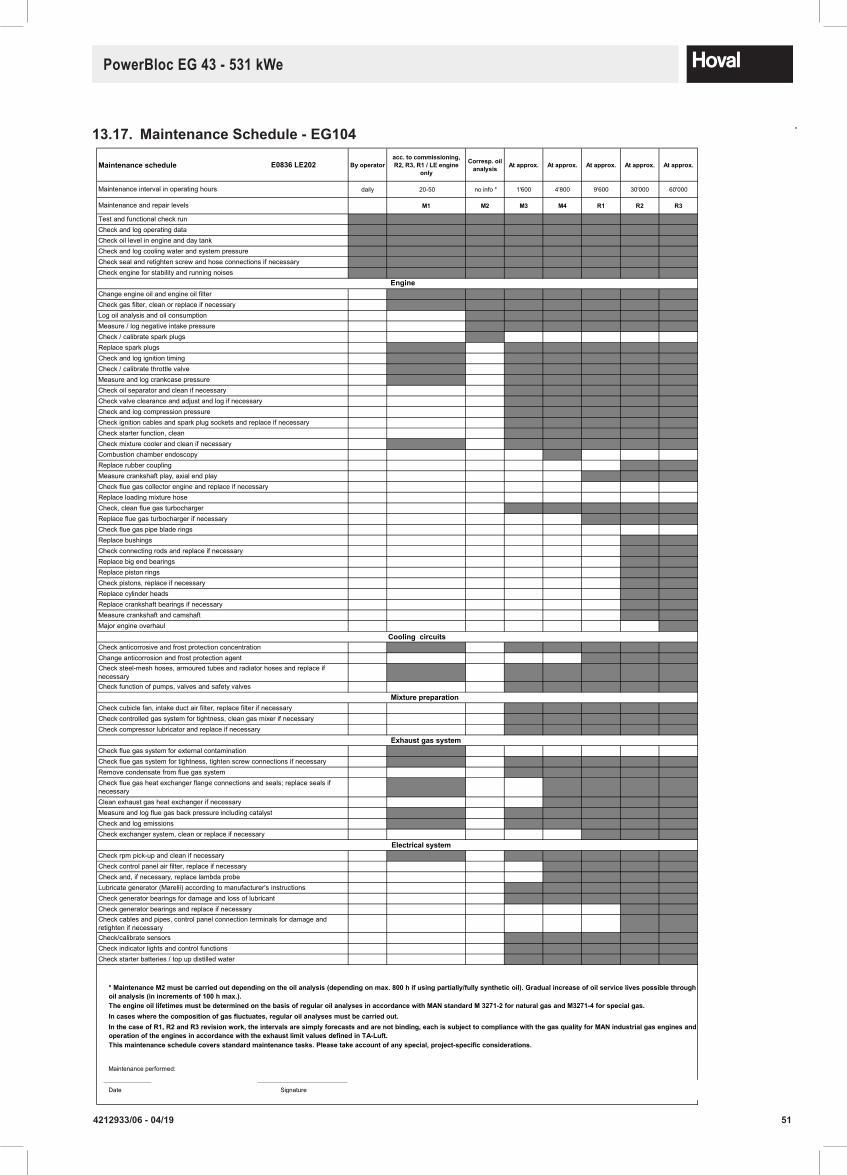
514212933/06 - 04/19
PowerBloc EG 43 - 531 kWe
13.17. MaintenanceSchedule-EG104
April 2017
Maintenanceschedule E0836 LE202 By operatoracc.tocommissioning,R2,R3,R1/LEengine
only
Corresp.oilanalysis At approx. At approx. At approx. At approx. At approx.
daily 20-50 no info * 1'600 4'800 9'600 30'000 60'000
M1 M2 M3 M4 R1 R2 R3
T T T T T T T T
T T T T T T T T
T T T T T T T T
T T T T T T T T
T T T T T T T T
T T T T T T T T
0 M1 M2 M2 M2 M2 M2 M2
0 M1 M2 M2 M2 M2 M2 M2
0 0 M2 M2 M2 M2 M2 M2
0 0 M2 M2 M2 M2 M2 M2
0 0 M2 0 0 0 0 0
0 M1 M3 M3 M3 M3 M3 M3
0 M1 M3 M3 M3 M3 M3 M3
0 M1 M3 M3 M3 M3 M3 M3
0 M1 M3 M3 M3 M3 M3 M3
0 0 M3 M3 M3 M3 M3 M3
0 0 M3 M3 M3 M3 M3 M3
0 0 M3 M3 M3 M3 M3 M3
0 0 M3 M3 M3 M3 M3 M3
0 0 M3 M3 M3 M3 M3 M3
0 M1 M3 M3 M3 M3 M3 M3
0 0 M4 M4 M4 M4 M4 M4
R2 R2 R2 R2 R2 R2
0 0 R1 R1 R1 R1 R1 R1
0 0 0 0 0 0 0 0
0 0 0 0 0 0 0 0
0 0 M3 M3 M3 M3 M3 M3
0 0 R1 R1 R1 R1 R1 R1
0 0 0 0 0 0 0 0
0 0 R2 R2 R2 R2 R2 R2
0 0 R2 R2 R2 R2 R2 R2
0 0 R2 R2 R2 R2 R2 R2
0 0 R2 R2 R2 R2 R2 R2
0 0 R2 R2 R2 R2 R2 R2
0 0 R2 R2 R2 R2 R2 R2
0 0 R2 R2 R2 R2 R2 R2
0 0 R2 R2 R2 R2 R2 R2
0 0 R3 R3 R3 R3 R3 R3
0 M1 M3 M3 M3 M3 M3 M3
0 0 R1 R1 R1 R1 R1 R1
0 M1 M3 M3 M3 M3 M3 M3
0 0 M3 M3 M3 M3 M3 M3
0 0 M3 M3 M3 M3 M3 M3
0 0 M3 M3 M3 M3 M3 M3
0 0 M3 M3 M3 M3 M3 M3
0 M1 0 0 0 0 0 0
0 M1 M3 M3 M3 M3 M3 M3
0 0 M3 M3 M3 M3 M3 M3
0 M1 M4 M4 M4 M4 M4 M4
0 0 M4 M4 M4 M4 M4 M4
0 M1 M3 M3 M3 M3 M3 M3
0 M1 M3 M3 M3 M3 M3 M3
0 0 R1 R1 R1 R1 R1 R1
0 M1 M3 M3 M3 M3 M3 M3
0 0 M4 M4 M4 M4 M4 M4
0 0 M4 M4 M4 M4 M4 M4
0 0 M3 M3 M3 M3 M3 M3
0 0 M3 M3 M3 M3 M3 M3
0 0 R2 R2 R2 R2 R2 R2
0 0 R2 R2 R2 R2 R2 R2
0 0 M3 M3 M3 M3 M3 M3
0 0 M3 M3 M3 M3 M3 M3
0 0 M3 M3 M3 M3 M3 M3
Date Signature
Check exchanger system, clean or replace if necessary
Check starter batteries / top up distilled water
Check generator bearings for damage and loss of lubricantLubricate generator (Marelli) according to manufacturer's instructions
Check generator bearings and replace if necessaryCheck cables and pipes, control panel connection terminals for damage and retighten if necessaryCheck/calibrate sensorsCheck indicator lights and control functions
Check control panel air filter, replace if necessaryCheck and, if necessary, replace lambda probe
Check rpm pick-up and clean if necessary
Check compressor lubricator and replace if necessary
Check cubicle fan, intake duct air filter, replace filter if necessary
Clean exhaust gas heat exchanger if necessary
Check flue gas system for tightness, tighten screw connections if necessary
Check flue gas heat exchanger flange connections and seals; replace seals if necessary
Remove condensate from flue gas system
Check flue gas system for external contamination
Check function of pumps, valves and safety valves
Check anticorrosive and frost protection concentration
Check steel-mesh hoses, armoured tubes and radiator hoses and replace if necessary
Change anticorrosion and frost protection agent
Check controlled gas system for tightness, clean gas mixer if necessary
Major engine overhaul
Check pistons, replace if necessaryReplace cylinder heads
Replace big end bearings
Replace crankshaft bearings if necessaryMeasure crankshaft and camshaft
Replace piston rings
Replace spark plugs
Check and log compression pressure
Check oil separator and clean if necessary
Check ignition cables and spark plug sockets and replace if necessary
Replace bushings
Check starter function, clean
Check and log ignition timing
Measure and log crankcase pressure
Check valve clearance and adjust and log if necessary
Measure crankshaft play, axial end play
Combustion chamber endoscopy
Replace flue gas turbocharger if necessaryCheck flue gas pipe blade rings
Check, clean flue gas turbocharger
Maintenance performed:
Maintenance interval in operating hours
Maintenance and repair levels
Test and functional check runCheck and log operating dataCheck oil level in engine and day tankCheck and log cooling water and system pressureCheck seal and retighten screw and hose connections if necessaryCheck engine for stability and running noises
Measure / log negative intake pressureCheck / calibrate spark plugs
Check gas filter, clean or replace if necessary
TheengineoillifetimesmustbedeterminedonthebasisofregularoilanalysesinaccordancewithMANstandardM3271-2fornaturalgasandM3271-4forspecialgas.
*MaintenanceM2mustbecarriedoutdependingontheoilanalysis(dependingonmax.800hifusingpartially/fullysyntheticoil).Gradualincreaseofoilservicelivespossiblethroughoilanalysis(inincrementsof100hmax.).
Incaseswherethecompositionofgasfluctuates,regularoilanalysesmustbecarriedout.InthecaseofR1,R2andR3revisionwork,theintervalsaresimplyforecastsandarenotbinding,eachissubjecttocompliancewiththegasqualityforMANindustrialgasenginesandoperationoftheenginesinaccordancewiththeexhaustlimitvaluesdefinedinTA-Luft.Thismaintenanceschedulecoversstandardmaintenancetasks.Pleasetakeaccountofanyspecial,project-specificconsiderations.
Log oil analysis and oil consumption
Change engine oil and engine oil filter
Replace rubber coupling
Replace loading mixture hose
Measure and log flue gas back pressure including catalystCheck and log emissions
Check connecting rods and replace if necessary
Check / calibrate throttle valve
Check mixture cooler and clean if necessary
Check flue gas collector engine and replace if necessary
CHP plant module EG-104
Electrical system
Exhaust gas system
Engine
Cooling circuits
Mixture preparation
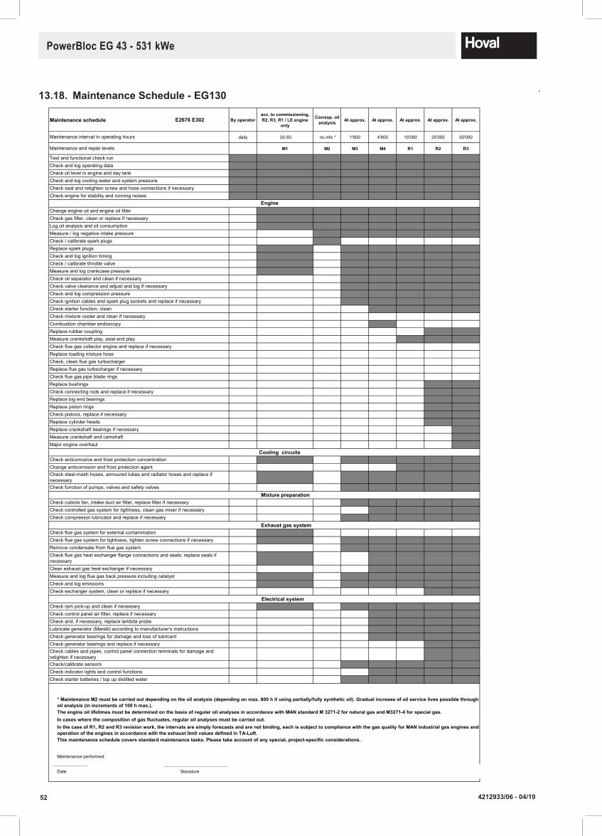
52 4212933/06 - 04/19
PowerBloc EG 43 - 531 kWe
13.18. MaintenanceSchedule-EG130
April 2017
Maintenanceschedule E2676 E302 By operatoracc.tocommissioning,R2,R3,R1/LEengine
only
Corresp.oilanalysis At approx. At approx. At approx. At approx. At approx.
daily 20-50 no info * 1'600 4'800 15'000 25'000 50'000
M1 M2 M3 M4 R1 R2 R3
T T T T T T T T
T T T T T T T T
T T T T T T T T
T T T T T T T T
T T T T T T T T
T T T T T T T T
0 M1 M2 M2 M2 M2 M2 M2
0 M1 M2 M2 M2 M2 M2 M2
0 M1 M2 M2 M2 M2 M2 M2
0 0 M2 M2 M2 M2 M2 M2
0 0 M2 0 0 0 0 0
0 M1 M3 M3 M3 M3 M3 M3
0 M1 M3 M3 M3 M3 M3 M3
0 M1 M3 M3 M3 M3 M3 M3
0 M1 M3 M3 M3 M3 M3 M3
0 0 M3 M3 M3 M3 M3 M3
0 0 M3 M3 M3 M3 M3 M3
0 0 M3 M3 M3 M3 M3 M3
0 0 M3 M3 M3 M3 M3 M3
0 0 M4 M4 M4 M4 M4 M4
0 0 0 0 0 0 0 0
0 0 M4 M4 M4 M4 M4 M4
R2 R2 R2 R2 R2 R2
0 0 R1 R1 R1 R1 R1 R1
0 0 0 0 0 0 0 0
0 0 0 0 0 0 0 0
0 0 0 0 0 0 0 0
0 0 0 0 0 0 0 0
0 0 0 0 0 0 0 0
0 0 R2 R2 R2 R2 R2 R2
0 0 R2 R2 R2 R2 R2 R2
0 0 R2 R2 R2 R2 R2 R2
0 0 R2 R2 R2 R2 R2 R2
0 0 R2 R2 R2 R2 R2 R2
0 0 R2 R2 R2 R2 R2 R2
0 0 R3 R3 R3 R3 R3 R3
0 0 R3 R3 R3 R3 R3 R3
0 0 R3 R3 R3 R3 R3 R3
0 M1 M3 M3 M3 M3 M3 M3
0 0 R1 R1 R1 R1 R1 R1
0 M1 M3 M3 M3 M3 M3 M3
0 0 M3 M3 M3 M3 M3 M3
0 0 M3 M3 M3 M3 M3 M3
0 0 M4 M4 M4 M4 M4 M4
0 0 M3 M3 M3 M3 M3 M3
0 M1 0 0 0 0 0 0
0 M1 M3 M3 M3 M3 M3 M3
0 0 M3 M3 M3 M3 M3 M3
0 M1 M4 M4 M4 M4 M4 M4
0 0 M4 M4 M4 M4 M4 M4
0 M1 M3 M3 M3 M3 M3 M3
0 M1 M3 M3 M3 M3 M3 M3
0 0 R2 R2 R2 R2 R2 R2
0 M1 M3 M3 M3 M3 M3 M3
0 0 M4 M4 M4 M4 M4 M4
0 0 M4 M4 M4 M4 M4 M4
0 0 M4 M4 M4 M4 M4 M4
0 0 M4 M4 M4 M4 M4 M4
0 0 R2 R2 R2 R2 R2 R2
0 0 R2 R2 R2 R2 R2 R2
0 0 M3 M3 M3 M3 M3 M3
0 0 M4 M4 M4 M4 M4 M4
0 0 M3 M3 M3 M3 M3 M3
Date Signature
Incaseswherethecompositionofgasfluctuates,regularoilanalysesmustbecarriedout.InthecaseofR1,R2andR3revisionwork,theintervalsaresimplyforecastsandarenotbinding,eachissubjecttocompliancewiththegasqualityforMANindustrialgasenginesandoperationoftheenginesinaccordancewiththeexhaustlimitvaluesdefinedinTA-Luft.Thismaintenanceschedulecoversstandardmaintenancetasks.Pleasetakeaccountofanyspecial,project-specificconsiderations.
Log oil analysis and oil consumption
Change engine oil and engine oil filter
Replace rubber coupling
Replace loading mixture hose
Measure and log flue gas back pressure including catalystCheck and log emissions
Check connecting rods and replace if necessary
Check / calibrate throttle valve
Check mixture cooler and clean if necessary
Check flue gas collector engine and replace if necessary
Maintenance performed:
Maintenance interval in operating hours
Maintenance and repair levels
Test and functional check runCheck and log operating dataCheck oil level in engine and day tankCheck and log cooling water and system pressureCheck seal and retighten screw and hose connections if necessaryCheck engine for stability and running noises
Measure / log negative intake pressureCheck / calibrate spark plugs
Check gas filter, clean or replace if necessary
TheengineoillifetimesmustbedeterminedonthebasisofregularoilanalysesinaccordancewithMANstandardM3271-2fornaturalgasandM3271-4forspecialgas.
*MaintenanceM2mustbecarriedoutdependingontheoilanalysis(dependingonmax.800hifusingpartially/fullysyntheticoil).Gradualincreaseofoilservicelivespossiblethroughoilanalysis(inincrementsof100hmax.).
Replace spark plugs
Check and log compression pressure
Check oil separator and clean if necessary
Check ignition cables and spark plug sockets and replace if necessary
Replace bushings
Check starter function, clean
Check and log ignition timing
Measure and log crankcase pressure
Check valve clearance and adjust and log if necessary
Measure crankshaft play, axial end play
Combustion chamber endoscopy
Replace flue gas turbocharger if necessaryCheck flue gas pipe blade rings
Check, clean flue gas turbocharger
Major engine overhaul
Check pistons, replace if necessaryReplace cylinder heads
Replace big end bearings
Replace crankshaft bearings if necessaryMeasure crankshaft and camshaft
Replace piston rings
Check function of pumps, valves and safety valves
Check anticorrosive and frost protection concentration
Check steel-mesh hoses, armoured tubes and radiator hoses and replace if necessary
Change anticorrosion and frost protection agent
Check controlled gas system for tightness, clean gas mixer if necessaryCheck compressor lubricator and replace if necessary
Check cubicle fan, intake duct air filter, replace filter if necessary
Clean exhaust gas heat exchanger if necessary
Check flue gas system for tightness, tighten screw connections if necessary
Check flue gas heat exchanger flange connections and seals; replace seals if necessary
Remove condensate from flue gas system
Check flue gas system for external contamination
Check exchanger system, clean or replace if necessary
Check starter batteries / top up distilled water
Check generator bearings for damage and loss of lubricantLubricate generator (Marelli) according to manufacturer's instructions
Check generator bearings and replace if necessaryCheck cables and pipes, control panel connection terminals for damage and retighten if necessaryCheck/calibrate sensorsCheck indicator lights and control functions
Check control panel air filter, replace if necessaryCheck and, if necessary, replace lambda probe
Check rpm pick-up and clean if necessary
CHP plant module EG-130
Electrical system
Exhaust gas system
Engine
Cooling circuits
Mixture preparation

534212933/06 - 04/19
PowerBloc EG 43 - 531 kWe
13.19. MaintenanceSchedule-EG210
April 2017
Maintenanceschedule E2676 LE202 By operatoracc.tocommissioning,R2,R3,R1/LEengine
only
Corresp.oilanalysis At approx. At approx. At approx. At approx. At approx.
daily 20-50 no info * 1'600 4'800 15'000 25'000 50'000
M1 M2 M3 M4 R1 R2 R3
T T T T T T T T
T T T T T T T T
T T T T T T T T
T T T T T T T T
T T T T T T T T
T T T T T T T T
0 M1 M2 M2 M2 M2 M2 M2
0 M1 M2 M2 M2 M2 M2 M2
0 0 M2 M2 M2 M2 M2 M2
0 0 M2 M2 M2 M2 M2 M2
0 0 M2 0 0 0 0 0
0 M1 M3 M3 M3 M3 M3 M3
0 M1 M3 M3 M3 M3 M3 M3
0 M1 M3 M3 M3 M3 M3 M3
0 M1 M3 M3 M3 M3 M3 M3
0 0 M3 M3 M3 M3 M3 M3
0 0 M3 M3 M3 M3 M3 M3
0 0 M3 M3 M3 M3 M3 M3
0 0 M3 M3 M3 M3 M3 M3
0 0 M4 M4 M4 M4 M4 M4
0 M1 M3 M3 M3 M3 M3 M3
0 0 M4 M4 M4 M4 M4 M4
R2 R2 R2 R2 R2 R2
0 0 R1 R1 R1 R1 R1 R1
0 0 0 0 0 0 0 0
0 0 R1 R1 R1 R1 R1 R1
0 0 M4 M4 M4 M4 M4 M4
0 0 R1 R1 R1 R1 R1 R1
0 0 0 0 0 0 0 0
0 0 R2 R2 R2 R2 R2 R2
0 0 R2 R2 R2 R2 R2 R2
0 0 R2 R2 R2 R2 R2 R2
0 0 R2 R2 R2 R2 R2 R2
0 0 R2 R2 R2 R2 R2 R2
0 0 R2 R2 R2 R2 R2 R2
0 0 R3 R3 R3 R3 R3 R3
0 0 R3 R3 R3 R3 R3 R3
0 0 R3 R3 R3 R3 R3 R3
0 M1 M3 M3 M3 M3 M3 M3
0 0 R1 R1 R1 R1 R1 R1
0 M1 M3 M3 M3 M3 M3 M3
0 0 M3 M3 M3 M3 M3 M3
0 0 M3 M3 M3 M3 M3 M3
0 0 M4 M4 M4 M4 M4 M4
0 0 M3 M3 M3 M3 M3 M3
0 M1 0 0 0 0 0 0
0 M1 M3 M3 M3 M3 M3 M3
0 0 M3 M3 M3 M3 M3 M3
0 M1 M4 M4 M4 M4 M4 M4
0 0 M4 M4 M4 M4 M4 M4
0 M1 M3 M3 M3 M3 M3 M3
0 M1 M3 M3 M3 M3 M3 M3
0 0 R1 R1 R1 R1 R1 R1
0 M1 M3 M3 M3 M3 M3 M3
0 0 M4 M4 M4 M4 M4 M4
0 0 M4 M4 M4 M4 M4 M4
0 0 M4 M4 M4 M4 M4 M4
0 0 M4 M4 M4 M4 M4 M4
0 0 R2 R2 R2 R2 R2 R2
0 0 R2 R2 R2 R2 R2 R2
0 0 M3 M3 M3 M3 M3 M3
0 0 M4 M4 M4 M4 M4 M4
0 0 M3 M3 M3 M3 M3 M3
Date Signature
Incaseswherethecompositionofgasfluctuates,regularoilanalysesmustbecarriedout.InthecaseofR1,R2andR3revisionwork,theintervalsaresimplyforecastsandarenotbinding,eachissubjecttocompliancewiththegasqualityforMANindustrialgasenginesandoperationoftheenginesinaccordancewiththeexhaustlimitvaluesdefinedinTA-Luft.Thismaintenanceschedulecoversstandardmaintenancetasks.Pleasetakeaccountofanyspecial,project-specificconsiderations.
Log oil analysis and oil consumption
Change engine oil and engine oil filter
Replace rubber coupling
Replace loading mixture hose
Measure and log flue gas back pressure including catalystCheck and log emissions
Check connecting rods and replace if necessary
Check / calibrate throttle valve
Check mixture cooler and clean if necessary
Check flue gas collector engine and replace if necessary
Maintenance performed:
Maintenance interval in operating hours
Maintenance and repair levels
Test and functional check runCheck and log operating dataCheck oil level in engine and day tankCheck and log cooling water and system pressureCheck seal and retighten screw and hose connections if necessaryCheck engine for stability and running noises
Measure / log negative intake pressureCheck / calibrate spark plugs
Check gas filter, clean or replace if necessary
TheengineoillifetimesmustbedeterminedonthebasisofregularoilanalysesinaccordancewithMANstandardM3271-2fornaturalgasandM3271-4forspecialgas.
*MaintenanceM2mustbecarriedoutdependingontheoilanalysis(dependingonmax.800hifusingpartially/fullysyntheticoil).Gradualincreaseofoilservicelivespossiblethroughoilanalysis(inincrementsof100hmax.).
Replace spark plugs
Check and log compression pressure
Check oil separator and clean if necessary
Check ignition cables and spark plug sockets and replace if necessary
Replace bushings
Check starter function, clean
Check and log ignition timing
Measure and log crankcase pressure
Check valve clearance and adjust and log if necessary
Measure crankshaft play, axial end play
Combustion chamber endoscopy
Replace flue gas turbocharger if necessaryCheck flue gas pipe blade rings
Check, clean flue gas turbocharger
Major engine overhaul
Check pistons, replace if necessaryReplace cylinder heads
Replace big end bearings
Replace crankshaft bearings if necessaryMeasure crankshaft and camshaft
Replace piston rings
Check function of pumps, valves and safety valves
Check anticorrosive and frost protection concentration
Check steel-mesh hoses, armoured tubes and radiator hoses and replace if necessary
Change anticorrosion and frost protection agent
Check controlled gas system for tightness, clean gas mixer if necessaryCheck compressor lubricator and replace if necessary
Check cubicle fan, intake duct air filter, replace filter if necessary
Clean exhaust gas heat exchanger if necessary
Check flue gas system for tightness, tighten screw connections if necessary
Check flue gas heat exchanger flange connections and seals; replace seals if necessary
Remove condensate from flue gas system
Check flue gas system for external contamination
Check exchanger system, clean or replace if necessary
Check starter batteries / top up distilled water
Check generator bearings for damage and loss of lubricantLubricate generator (Marelli) according to manufacturer's instructions
Check generator bearings and replace if necessaryCheck cables and pipes, control panel connection terminals for damage and retighten if necessaryCheck/calibrate sensorsCheck indicator lights and control functions
Check control panel air filter, replace if necessaryCheck and, if necessary, replace lambda probe
Check rpm pick-up and clean if necessary
CHP plant module EG-210
Electrical system
Exhaust gas system
Engine
Cooling circuits
Mixture preparation

54 4212933/06 - 04/19
PowerBloc EG 43 - 531 kWe
13.20. MaintenanceSchedule-EG210NOx
April 2017
Maintenanceschedule E2676 LE202 By operatoracc.tocommissioning,R2,R3,R1/LEengine
only
Corresp.oilanalysis At approx. At approx. At approx. At approx. At approx.
daily 20-50 no info * 1'600 4'800 15'000 25'000 50'000
M1 M2 M3 M4 R1 R2 R3
T T T T T T T T
T T T T T T T T
T T T T T T T T
T T T T T T T T
T T T T T T T T
T T T T T T T T
0 M1 M2 M2 M2 M2 M2 M2
0 M1 M2 M2 M2 M2 M2 M2
0 0 M2 M2 M2 M2 M2 M2
0 0 M2 M2 M2 M2 M2 M2
0 0 M2 0 0 0 0 0
0 M1 M3 M3 M3 M3 M3 M3
0 M1 M3 M3 M3 M3 M3 M3
0 M1 M3 M3 M3 M3 M3 M3
0 M1 M3 M3 M3 M3 M3 M3
0 0 M3 M3 M3 M3 M3 M3
0 0 M3 M3 M3 M3 M3 M3
0 0 M3 M3 M3 M3 M3 M3
0 0 M3 M3 M3 M3 M3 M3
0 0 M4 M4 M4 M4 M4 M4
0 M1 M3 M3 M3 M3 M3 M3
0 0 M4 M4 M4 M4 M4 M4
R2 R2 R2 R2 R2 R2
0 0 R1 R1 R1 R1 R1 R1
0 0 0 0 0 0 0 0
0 0 R1 R1 R1 R1 R1 R1
0 0 M4 M4 M4 M4 M4 M4
0 0 R1 R1 R1 R1 R1 R1
0 0 0 0 0 0 0 0
0 0 R2 R2 R2 R2 R2 R2
0 0 R2 R2 R2 R2 R2 R2
0 0 R2 R2 R2 R2 R2 R2
0 0 R2 R2 R2 R2 R2 R2
0 0 R2 R2 R2 R2 R2 R2
0 0 R2 R2 R2 R2 R2 R2
0 0 R3 R3 R3 R3 R3 R3
0 0 R3 R3 R3 R3 R3 R3
0 0 R3 R3 R3 R3 R3 R3
0 M1 M3 M3 M3 M3 M3 M3
0 0 R1 R1 R1 R1 R1 R1
0 M1 M3 M3 M3 M3 M3 M3
0 0 M3 M3 M3 M3 M3 M3
0 0 M3 M3 M3 M3 M3 M3
0 0 M4 M4 M4 M4 M4 M4
0 0 M3 M3 M3 M3 M3 M3
0 M1 0 0 0 0 0 0
0 M1 M3 M3 M3 M3 M3 M3
0 0 M3 M3 M3 M3 M3 M3
0 M1 M4 M4 M4 M4 M4 M4
0 0 M4 M4 M4 M4 M4 M4
0 M1 M3 M3 M3 M3 M3 M3
0 M1 M3 M3 M3 M3 M3 M3
0 0 R1 R1 R1 R1 R1 R1
0 M1 M3 M3 M3 M3 M3 M3
0 0 M4 M4 M4 M4 M4 M4
0 0 M4 M4 M4 M4 M4 M4
0 0 M4 M4 M4 M4 M4 M4
0 0 M4 M4 M4 M4 M4 M4
0 0 R2 R2 R2 R2 R2 R2
0 0 R2 R2 R2 R2 R2 R2
0 0 M3 M3 M3 M3 M3 M3
0 0 M4 M4 M4 M4 M4 M4
0 0 M3 M3 M3 M3 M3 M3
Date Signature
Incaseswherethecompositionofgasfluctuates,regularoilanalysesmustbecarriedout.InthecaseofR1,R2andR3revisionwork,theintervalsaresimplyforecastsandarenotbinding,eachissubjecttocompliancewiththegasqualityforMANindustrialgasenginesandoperationoftheenginesinaccordancewiththeexhaustlimitvaluesdefinedinTA-Luft.Thismaintenanceschedulecoversstandardmaintenancetasks.Pleasetakeaccountofanyspecial,project-specificconsiderations.
Log oil analysis and oil consumption
Change engine oil and engine oil filter
Replace rubber coupling
Replace loading mixture hose
Measure and log flue gas back pressure including catalystCheck and log emissions
Check connecting rods and replace if necessary
Check / calibrate throttle valve
Check mixture cooler and clean if necessary
Check flue gas collector engine and replace if necessary
Maintenance performed:
Maintenance interval in operating hours
Maintenance and repair levels
Test and functional check runCheck and log operating dataCheck oil level in engine and day tankCheck and log cooling water and system pressureCheck seal and retighten screw and hose connections if necessaryCheck engine for stability and running noises
Measure / log negative intake pressureCheck / calibrate spark plugs
Check gas filter, clean or replace if necessary
TheengineoillifetimesmustbedeterminedonthebasisofregularoilanalysesinaccordancewithMANstandardM3271-2fornaturalgasandM3271-4forspecialgas.
*MaintenanceM2mustbecarriedoutdependingontheoilanalysis(dependingonmax.800hifusingpartially/fullysyntheticoil).Gradualincreaseofoilservicelivespossiblethroughoilanalysis(inincrementsof100hmax.).
Replace spark plugs
Check and log compression pressure
Check oil separator and clean if necessary
Check ignition cables and spark plug sockets and replace if necessary
Replace bushings
Check starter function, clean
Check and log ignition timing
Measure and log crankcase pressure
Check valve clearance and adjust and log if necessary
Measure crankshaft play, axial end play
Combustion chamber endoscopy
Replace flue gas turbocharger if necessaryCheck flue gas pipe blade rings
Check, clean flue gas turbocharger
Major engine overhaul
Check pistons, replace if necessaryReplace cylinder heads
Replace big end bearings
Replace crankshaft bearings if necessaryMeasure crankshaft and camshaft
Replace piston rings
Check function of pumps, valves and safety valves
Check anticorrosive and frost protection concentration
Check steel-mesh hoses, armoured tubes and radiator hoses and replace if necessary
Change anticorrosion and frost protection agent
Check controlled gas system for tightness, clean gas mixer if necessaryCheck compressor lubricator and replace if necessary
Check cubicle fan, intake duct air filter, replace filter if necessary
Clean exhaust gas heat exchanger if necessary
Check flue gas system for tightness, tighten screw connections if necessary
Check flue gas heat exchanger flange connections and seals; replace seals if necessary
Remove condensate from flue gas system
Check flue gas system for external contamination
Check exchanger system, clean or replace if necessary
Check starter batteries / top up distilled water
Check generator bearings for damage and loss of lubricantLubricate generator (Marelli) according to manufacturer's instructions
Check generator bearings and replace if necessaryCheck cables and pipes, control panel connection terminals for damage and retighten if necessaryCheck/calibrate sensorsCheck indicator lights and control functions
Check control panel air filter, replace if necessaryCheck and, if necessary, replace lambda probe
Check rpm pick-up and clean if necessary
CHP plant module EG-210NOx
Electrical system
Exhaust gas system
Engine
Cooling circuits
Mixture preparation
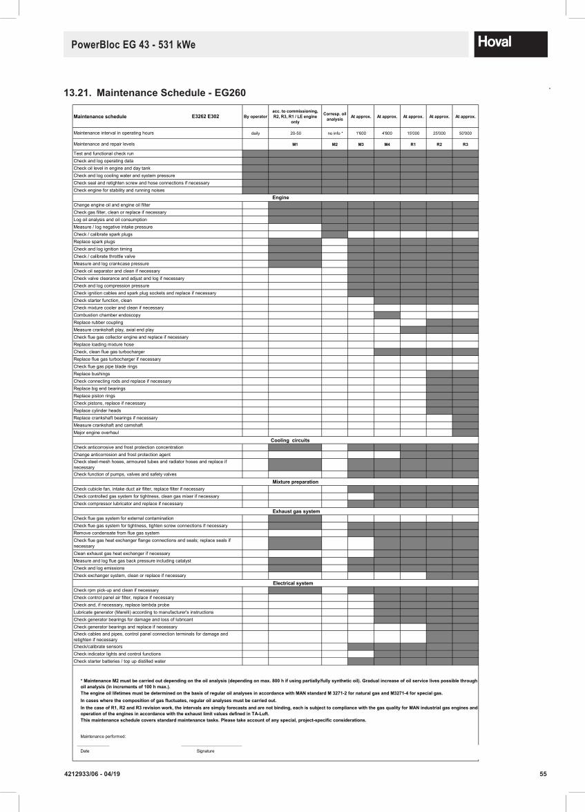
554212933/06 - 04/19
PowerBloc EG 43 - 531 kWe
13.21. MaintenanceSchedule-EG260
April 2017
Maintenanceschedule E3262 E302 By operatoracc.tocommissioning,R2,R3,R1/LEengine
only
Corresp.oilanalysis At approx. At approx. At approx. At approx. At approx.
daily 20-50 no info * 1'600 4'800 15'000 25'000 50'000
M1 M2 M3 M4 R1 R2 R3
T T T T T T T T
T T T T T T T T
T T T T T T T T
T T T T T T T T
T T T T T T T T
T T T T T T T T
0 M1 M2 M2 M2 M2 M2 M2
0 M1 M2 M2 M2 M2 M2 M2
0 M1 M2 M2 M2 M2 M2 M2
0 0 M2 M2 M2 M2 M2 M2
0 0 M2 0 0 0 0 0
0 M1 M3 M3 M3 M3 M3 M3
0 M1 M3 M3 M3 M3 M3 M3
0 M1 M3 M3 M3 M3 M3 M3
0 M1 M3 M3 M3 M3 M3 M3
0 0 M3 M3 M3 M3 M3 M3
0 0 M3 M3 M3 M3 M3 M3
0 0 M3 M3 M3 M3 M3 M3
0 0 M3 M3 M3 M3 M3 M3
0 0 M4 M4 M4 M4 M4 M4
0 0 0 0 0 0 0 0
0 0 M4 M4 M4 M4 M4 M4
R2 R2 R2 R2 R2 R2
0 0 R1 R1 R1 R1 R1 R1
0 0 0 0 0 0 0 0
0 0 0 0 0 0 0 0
0 0 M4 M4 M4 M4 M4 M4
0 0 0 0 0 0 0 0
0 0 0 0 0 0 0 0
0 0 R2 R2 R2 R2 R2 R2
0 0 R2 R2 R2 R2 R2 R2
0 0 R2 R2 R2 R2 R2 R2
0 0 R2 R2 R2 R2 R2 R2
0 0 R2 R2 R2 R2 R2 R2
0 0 R2 R2 R2 R2 R2 R2
0 0 R3 R3 R3 R3 R3 R3
0 0 R3 R3 R3 R3 R3 R3
0 0 R3 R3 R3 R3 R3 R3
0 M1 M3 M3 M3 M3 M3 M3
0 0 R1 R1 R1 R1 R1 R1
0 M1 M3 M3 M3 M3 M3 M3
0 0 M3 M3 M3 M3 M3 M3
0 0 M3 M3 M3 M3 M3 M3
0 0 M4 M4 M4 M4 M4 M4
0 0 M3 M3 M3 M3 M3 M3
0 M1 0 0 0 0 0 0
0 M1 M3 M3 M3 M3 M3 M3
0 0 M3 M3 M3 M3 M3 M3
0 M1 M4 M4 M4 M4 M4 M4
0 0 M4 M4 M4 M4 M4 M4
0 M1 M3 M3 M3 M3 M3 M3
0 M1 M3 M3 M3 M3 M3 M3
0 0 R2 R2 R2 R2 R2 R2
0 M1 M3 M3 M3 M3 M3 M3
0 0 M4 M4 M4 M4 M4 M4
0 0 M4 M4 M4 M4 M4 M4
0 0 M4 M4 M4 M4 M4 M4
0 0 M4 M4 M4 M4 M4 M4
0 0 R2 R2 R2 R2 R2 R2
0 0 R2 R2 R2 R2 R2 R2
0 0 M3 M3 M3 M3 M3 M3
0 0 M4 M4 M4 M4 M4 M4
0 0 M3 M3 M3 M3 M3 M3
Date Signature
Check exchanger system, clean or replace if necessary
Check starter batteries / top up distilled water
Check generator bearings for damage and loss of lubricantLubricate generator (Marelli) according to manufacturer's instructions
Check generator bearings and replace if necessaryCheck cables and pipes, control panel connection terminals for damage and retighten if necessaryCheck/calibrate sensorsCheck indicator lights and control functions
Check control panel air filter, replace if necessaryCheck and, if necessary, replace lambda probe
Check rpm pick-up and clean if necessary
Check compressor lubricator and replace if necessary
Check cubicle fan, intake duct air filter, replace filter if necessary
Clean exhaust gas heat exchanger if necessary
Check flue gas system for tightness, tighten screw connections if necessary
Check flue gas heat exchanger flange connections and seals; replace seals if necessary
Remove condensate from flue gas system
Check flue gas system for external contamination
Check function of pumps, valves and safety valves
Check anticorrosive and frost protection concentration
Check steel-mesh hoses, armoured tubes and radiator hoses and replace if necessary
Change anticorrosion and frost protection agent
Check controlled gas system for tightness, clean gas mixer if necessary
Major engine overhaul
Check pistons, replace if necessaryReplace cylinder heads
Replace big end bearings
Replace crankshaft bearings if necessaryMeasure crankshaft and camshaft
Replace piston rings
Replace spark plugs
Check and log compression pressure
Check oil separator and clean if necessary
Check ignition cables and spark plug sockets and replace if necessary
Replace bushings
Check starter function, clean
Check and log ignition timing
Measure and log crankcase pressure
Check valve clearance and adjust and log if necessary
Measure crankshaft play, axial end play
Combustion chamber endoscopy
Replace flue gas turbocharger if necessaryCheck flue gas pipe blade rings
Check, clean flue gas turbocharger
Maintenance performed:
Maintenance interval in operating hours
Maintenance and repair levels
Test and functional check runCheck and log operating dataCheck oil level in engine and day tankCheck and log cooling water and system pressureCheck seal and retighten screw and hose connections if necessaryCheck engine for stability and running noises
Measure / log negative intake pressureCheck / calibrate spark plugs
Check gas filter, clean or replace if necessary
TheengineoillifetimesmustbedeterminedonthebasisofregularoilanalysesinaccordancewithMANstandardM3271-2fornaturalgasandM3271-4forspecialgas.
*MaintenanceM2mustbecarriedoutdependingontheoilanalysis(dependingonmax.800hifusingpartially/fullysyntheticoil).Gradualincreaseofoilservicelivespossiblethroughoilanalysis(inincrementsof100hmax.).
Incaseswherethecompositionofgasfluctuates,regularoilanalysesmustbecarriedout.InthecaseofR1,R2andR3revisionwork,theintervalsaresimplyforecastsandarenotbinding,eachissubjecttocompliancewiththegasqualityforMANindustrialgasenginesandoperationoftheenginesinaccordancewiththeexhaustlimitvaluesdefinedinTA-Luft.Thismaintenanceschedulecoversstandardmaintenancetasks.Pleasetakeaccountofanyspecial,project-specificconsiderations.
Log oil analysis and oil consumption
Change engine oil and engine oil filter
Replace rubber coupling
Replace loading mixture hose
Measure and log flue gas back pressure including catalystCheck and log emissions
Check connecting rods and replace if necessary
Check / calibrate throttle valve
Check mixture cooler and clean if necessary
Check flue gas collector engine and replace if necessary
CHP plant module EG-260
Electrical system
Exhaust gas system
Engine
Cooling circuits
Mixture preparation
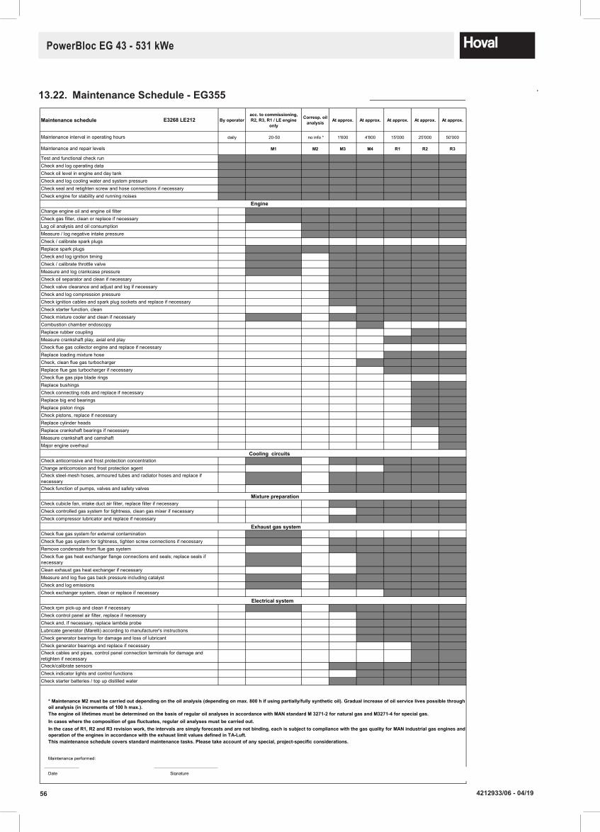
56 4212933/06 - 04/19
PowerBloc EG 43 - 531 kWe
13.22. MaintenanceSchedule-EG355
April 2017
Maintenanceschedule E3268 LE212 By operatoracc.tocommissioning,R2,R3,R1/LEengine
only
Corresp.oilanalysis At approx. At approx. At approx. At approx. At approx.
daily 20-50 no info * 1'600 4'800 15'000 25'000 50'000
M1 M2 M3 M4 R1 R2 R3
T T T T T T T T
T T T T T T T T
T T T T T T T T
T T T T T T T T
T T T T T T T T
T T T T T T T T
0 M1 M2 M2 M2 M2 M2 M2
0 M1 M2 M2 M2 M2 M2 M2
0 0 M2 M2 M2 M2 M2 M2
0 0 M2 M2 M2 M2 M2 M2
0 0 0 0 0 0 0 0
0 M1 M2 M2 M2 M2 M2 M2
0 M1 M3 M3 M3 M3 M3 M3
0 M1 M3 M3 M3 M3 M3 M3
0 M1 M3 M3 M3 M3 M3 M3
0 0 M3 M3 M3 M3 M3 M3
0 0 M3 M3 M3 M3 M3 M3
0 0 M3 M3 M3 M3 M3 M3
0 0 M3 M3 M3 M3 M3 M3
0 0 M4 M4 M4 M4 M4 M4
0 M1 M3 M3 M3 M3 M3 M3
0 0 M4 M4 M4 M4 M4 M4
R2 R2 R2 R2 R2 R2
0 0 R1 R1 R1 R1 R1 R1
0 0 0 0 0 0 0 0
0 0 R1 R1 R1 R1 R1 R1
0 0 M4 M4 M4 M4 M4 M4
0 0 R1 R1 R1 R1 R1 R1
0 0 0 0 0 0 0 0
0 0 R2 R2 R2 R2 R2 R2
0 0 R2 R2 R2 R2 R2 R2
0 0 R2 R2 R2 R2 R2 R2
0 0 R2 R2 R2 R2 R2 R2
0 0 R2 R2 R2 R2 R2 R2
0 0 R2 R2 R2 R2 R2 R2
0 0 R3 R3 R3 R3 R3 R3
0 0 R3 R3 R3 R3 R3 R3
0 0 R3 R3 R3 R3 R3 R3
0 M1 M3 M3 M3 M3 M3 M3
0 0 R1 R1 R1 R1 R1 R1
0 M1 M3 M3 M3 M3 M3 M3
0 0 M3 M3 M3 M3 M3 M3
0 0 M3 M3 M3 M3 M3 M3
0 0 M4 M4 M4 M4 M4 M4
0 0 M3 M3 M3 M3 M3 M3
0 M1 0 0 0 0 0 0
0 M1 M3 M3 M3 M3 M3 M3
0 0 M3 M3 M3 M3 M3 M3
0 M1 M4 M4 M4 M4 M4 M4
0 0 M4 M4 M4 M4 M4 M4
0 M1 M3 M3 M3 M3 M3 M3
0 M1 M3 M3 M3 M3 M3 M3
0 0 R1 R1 R1 R1 R1 R1
0 M1 M3 M3 M3 M3 M3 M3
0 0 M4 M4 M4 M4 M4 M4
0 0 M4 M4 M4 M4 M4 M4
0 0 M4 M4 M4 M4 M4 M4
0 0 M4 M4 M4 M4 M4 M4
0 0 R2 R2 R2 R2 R2 R2
0 0 R2 R2 R2 R2 R2 R2
0 0 M3 M3 M3 M3 M3 M3
0 0 M4 M4 M4 M4 M4 M4
0 0 M3 M3 M3 M3 M3 M3
Date Signature
Check exchanger system, clean or replace if necessary
Check starter batteries / top up distilled water
Check generator bearings for damage and loss of lubricantLubricate generator (Marelli) according to manufacturer's instructions
Check generator bearings and replace if necessaryCheck cables and pipes, control panel connection terminals for damage and retighten if necessaryCheck/calibrate sensorsCheck indicator lights and control functions
Check control panel air filter, replace if necessaryCheck and, if necessary, replace lambda probe
Check rpm pick-up and clean if necessary
Check compressor lubricator and replace if necessary
Check cubicle fan, intake duct air filter, replace filter if necessary
Clean exhaust gas heat exchanger if necessary
Check flue gas system for tightness, tighten screw connections if necessary
Check flue gas heat exchanger flange connections and seals; replace seals if necessary
Remove condensate from flue gas system
Check flue gas system for external contamination
Check function of pumps, valves and safety valves
Check anticorrosive and frost protection concentration
Check steel-mesh hoses, armoured tubes and radiator hoses and replace if necessary
Change anticorrosion and frost protection agent
Check controlled gas system for tightness, clean gas mixer if necessary
Major engine overhaul
Check pistons, replace if necessaryReplace cylinder heads
Replace big end bearings
Replace crankshaft bearings if necessaryMeasure crankshaft and camshaft
Replace piston rings
Replace spark plugs
Check and log compression pressure
Check oil separator and clean if necessary
Check ignition cables and spark plug sockets and replace if necessary
Replace bushings
Check starter function, clean
Check and log ignition timing
Measure and log crankcase pressure
Check valve clearance and adjust and log if necessary
Measure crankshaft play, axial end play
Combustion chamber endoscopy
Replace flue gas turbocharger if necessaryCheck flue gas pipe blade rings
Check, clean flue gas turbocharger
Maintenance performed:
Maintenance interval in operating hours
Maintenance and repair levels
Test and functional check runCheck and log operating dataCheck oil level in engine and day tankCheck and log cooling water and system pressureCheck seal and retighten screw and hose connections if necessaryCheck engine for stability and running noises
Measure / log negative intake pressureCheck / calibrate spark plugs
Check gas filter, clean or replace if necessary
TheengineoillifetimesmustbedeterminedonthebasisofregularoilanalysesinaccordancewithMANstandardM3271-2fornaturalgasandM3271-4forspecialgas.
*MaintenanceM2mustbecarriedoutdependingontheoilanalysis(dependingonmax.800hifusingpartially/fullysyntheticoil).Gradualincreaseofoilservicelivespossiblethroughoilanalysis(inincrementsof100hmax.).
Incaseswherethecompositionofgasfluctuates,regularoilanalysesmustbecarriedout.InthecaseofR1,R2andR3revisionwork,theintervalsaresimplyforecastsandarenotbinding,eachissubjecttocompliancewiththegasqualityforMANindustrialgasenginesandoperationoftheenginesinaccordancewiththeexhaustlimitvaluesdefinedinTA-Luft.Thismaintenanceschedulecoversstandardmaintenancetasks.Pleasetakeaccountofanyspecial,project-specificconsiderations.
Log oil analysis and oil consumption
Change engine oil and engine oil filter
Replace rubber coupling
Replace loading mixture hose
Measure and log flue gas back pressure including catalystCheck and log emissions
Check connecting rods and replace if necessary
Check / calibrate throttle valve
Check mixture cooler and clean if necessary
Check flue gas collector engine and replace if necessary
CHP plant module EG-355
Electrical system
Exhaust gas system
Engine
Cooling circuits
Mixture preparation

574212933/06 - 04/19
PowerBloc EG 43 - 531 kWe
13.23. MaintenanceSchedule-EG355/NOx
April 2017
Maintenanceschedule E3268 LE212 By operatoracc.tocommissioning,R2,R3,R1/LEengine
only
Corresp.oilanalysis At approx. At approx. At approx. At approx. At approx.
daily 20-50 no info * 1'600 4'800 15'000 25'000 50'000
M1 M2 M3 M4 R1 R2 R3
T T T T T T T T
T T T T T T T T
T T T T T T T T
T T T T T T T T
T T T T T T T T
T T T T T T T T
0 M1 M2 M2 M2 M2 M2 M2
0 M1 M2 M2 M2 M2 M2 M2
0 0 M2 M2 M2 M2 M2 M2
0 0 M2 M2 M2 M2 M2 M2
0 0 0 0 0 0 0 0
0 M1 M2 M2 M2 M2 M2 M2
0 M1 M3 M3 M3 M3 M3 M3
0 M1 M3 M3 M3 M3 M3 M3
0 M1 M3 M3 M3 M3 M3 M3
0 0 M3 M3 M3 M3 M3 M3
0 0 M3 M3 M3 M3 M3 M3
0 0 M3 M3 M3 M3 M3 M3
0 0 M3 M3 M3 M3 M3 M3
0 0 M4 M4 M4 M4 M4 M4
0 M1 M3 M3 M3 M3 M3 M3
0 0 M4 M4 M4 M4 M4 M4
R2 R2 R2 R2 R2 R2
0 0 R1 R1 R1 R1 R1 R1
0 0 0 0 0 0 0 0
0 0 R1 R1 R1 R1 R1 R1
0 0 M4 M4 M4 M4 M4 M4
0 0 R1 R1 R1 R1 R1 R1
0 0 0 0 0 0 0 0
0 0 R2 R2 R2 R2 R2 R2
0 0 R2 R2 R2 R2 R2 R2
0 0 R2 R2 R2 R2 R2 R2
0 0 R2 R2 R2 R2 R2 R2
0 0 R2 R2 R2 R2 R2 R2
0 0 R2 R2 R2 R2 R2 R2
0 0 R3 R3 R3 R3 R3 R3
0 0 R3 R3 R3 R3 R3 R3
0 0 R3 R3 R3 R3 R3 R3
0 M1 M3 M3 M3 M3 M3 M3
0 0 R1 R1 R1 R1 R1 R1
0 M1 M3 M3 M3 M3 M3 M3
0 0 M3 M3 M3 M3 M3 M3
0 0 M3 M3 M3 M3 M3 M3
0 0 M4 M4 M4 M4 M4 M4
0 0 M3 M3 M3 M3 M3 M3
0 M1 0 0 0 0 0 0
0 M1 M3 M3 M3 M3 M3 M3
0 0 M3 M3 M3 M3 M3 M3
0 M1 M4 M4 M4 M4 M4 M4
0 0 M4 M4 M4 M4 M4 M4
0 M1 M3 M3 M3 M3 M3 M3
0 M1 M3 M3 M3 M3 M3 M3
0 0 R1 R1 R1 R1 R1 R1
0 M1 M3 M3 M3 M3 M3 M3
0 0 M4 M4 M4 M4 M4 M4
0 0 M4 M4 M4 M4 M4 M4
0 0 M4 M4 M4 M4 M4 M4
0 0 M4 M4 M4 M4 M4 M4
0 0 R2 R2 R2 R2 R2 R2
0 0 R2 R2 R2 R2 R2 R2
0 0 M3 M3 M3 M3 M3 M3
0 0 M4 M4 M4 M4 M4 M4
0 0 M3 M3 M3 M3 M3 M3
Date Signature
Incaseswherethecompositionofgasfluctuates,regularoilanalysesmustbecarriedout.InthecaseofR1,R2andR3revisionwork,theintervalsaresimplyforecastsandarenotbinding,eachissubjecttocompliancewiththegasqualityforMANindustrialgasenginesandoperationoftheenginesinaccordancewiththeexhaustlimitvaluesdefinedinTA-Luft.Thismaintenanceschedulecoversstandardmaintenancetasks.Pleasetakeaccountofanyspecial,project-specificconsiderations.
Log oil analysis and oil consumption
Change engine oil and engine oil filter
Replace rubber coupling
Replace loading mixture hose
Measure and log flue gas back pressure including catalystCheck and log emissions
Check connecting rods and replace if necessary
Check / calibrate throttle valve
Check mixture cooler and clean if necessary
Check flue gas collector engine and replace if necessary
Maintenance performed:
Maintenance interval in operating hours
Maintenance and repair levels
Test and functional check runCheck and log operating dataCheck oil level in engine and day tankCheck and log cooling water and system pressureCheck seal and retighten screw and hose connections if necessaryCheck engine for stability and running noises
Measure / log negative intake pressureCheck / calibrate spark plugs
Check gas filter, clean or replace if necessary
TheengineoillifetimesmustbedeterminedonthebasisofregularoilanalysesinaccordancewithMANstandardM3271-2fornaturalgasandM3271-4forspecialgas.
*MaintenanceM2mustbecarriedoutdependingontheoilanalysis(dependingonmax.800hifusingpartially/fullysyntheticoil).Gradualincreaseofoilservicelivespossiblethroughoilanalysis(inincrementsof100hmax.).
Replace spark plugs
Check and log compression pressure
Check oil separator and clean if necessary
Check ignition cables and spark plug sockets and replace if necessary
Replace bushings
Check starter function, clean
Check and log ignition timing
Measure and log crankcase pressure
Check valve clearance and adjust and log if necessary
Measure crankshaft play, axial end play
Combustion chamber endoscopy
Replace flue gas turbocharger if necessaryCheck flue gas pipe blade rings
Check, clean flue gas turbocharger
Major engine overhaul
Check pistons, replace if necessaryReplace cylinder heads
Replace big end bearings
Replace crankshaft bearings if necessaryMeasure crankshaft and camshaft
Replace piston rings
Check function of pumps, valves and safety valves
Check anticorrosive and frost protection concentration
Check steel-mesh hoses, armoured tubes and radiator hoses and replace if necessary
Change anticorrosion and frost protection agent
Check controlled gas system for tightness, clean gas mixer if necessaryCheck compressor lubricator and replace if necessary
Check cubicle fan, intake duct air filter, replace filter if necessary
Clean exhaust gas heat exchanger if necessary
Check flue gas system for tightness, tighten screw connections if necessary
Check flue gas heat exchanger flange connections and seals; replace seals if necessary
Remove condensate from flue gas system
Check flue gas system for external contamination
Check exchanger system, clean or replace if necessary
Check starter batteries / top up distilled water
Check generator bearings for damage and loss of lubricantLubricate generator (Marelli) according to manufacturer's instructions
Check generator bearings and replace if necessaryCheck cables and pipes, control panel connection terminals for damage and retighten if necessaryCheck/calibrate sensorsCheck indicator lights and control functions
Check control panel air filter, replace if necessaryCheck and, if necessary, replace lambda probe
Check rpm pick-up and clean if necessary
CHP plant module EG-355NOx
Electrical system
Exhaust gas system
Engine
Cooling circuits
Mixture preparation

58 4212933/06 - 04/19
PowerBloc EG 43 - 531 kWe
13.24. MaintenanceSchedule-EG430
TBC

594212933/06 - 04/19
PowerBloc EG 43 - 531 kWe
13.25. MaintenanceSchedule-EG430/NOx
TBC

60 4212933/06 - 04/19
PowerBloc EG 43 - 531 kWe
13.26. MaintenanceSchedule-EG530
April 2017
Maintenance schedule E3262 LE202 By operatoracc. to commissioning, R2, R3, R1 / LE engine
only
Corresp. oil analysis At approx. At approx. At approx. At approx. At approx.
daily 20-50 no info * 1'600 4'800 15'000 25'000 50'000
M1 M2 M3 M4 R1 R2 R3
T T T T T T T T
T T T T T T T T
T T T T T T T T
T T T T T T T T
T T T T T T T T
T T T T T T T T
0 M1 M2 M2 M2 M2 M2 M2
0 M1 M2 M2 M2 M2 M2 M2
0 0 M2 M2 M2 M2 M2 M2
0 0 M2 M2 M2 M2 M2 M2
0 0 0 0 0 0 0 0
0 M1 M2 M2 M2 M2 M2 M2
0 M1 M3 M3 M3 M3 M3 M3
0 M1 M3 M3 M3 M3 M3 M3
0 M1 M3 M3 M3 M3 M3 M3
0 0 M3 M3 M3 M3 M3 M3
0 0 M3 M3 M3 M3 M3 M3
0 0 M3 M3 M3 M3 M3 M3
0 0 M3 M3 M3 M3 M3 M3
0 0 M4 M4 M4 M4 M4 M4
0 M1 M3 M3 M3 M3 M3 M3
0 0 M4 M4 M4 M4 M4 M4
R2 R2 R2 R2 R2 R2
0 0 R1 R1 R1 R1 R1 R1
0 0 0 0 0 0 0 0
0 0 R1 R1 R1 R1 R1 R1
0 0 M4 M4 M4 M4 M4 M4
0 0 R1 R1 R1 R1 R1 R1
0 0 0 0 0 0 0 0
0 0 R2 R2 R2 R2 R2 R2
0 0 R2 R2 R2 R2 R2 R2
0 0 R2 R2 R2 R2 R2 R2
0 0 R2 R2 R2 R2 R2 R2
0 0 R2 R2 R2 R2 R2 R2
0 0 R2 R2 R2 R2 R2 R2
0 0 R3 R3 R3 R3 R3 R3
0 0 R3 R3 R3 R3 R3 R3
0 0 R3 R3 R3 R3 R3 R3
0 M1 M3 M3 M3 M3 M3 M3
0 0 R1 R1 R1 R1 R1 R1
0 M1 M3 M3 M3 M3 M3 M3
0 0 M3 M3 M3 M3 M3 M3
0 0 M3 M3 M3 M3 M3 M3
0 0 M4 M4 M4 M4 M4 M4
0 0 M3 M3 M3 M3 M3 M3
0 M1 0 0 0 0 0 0
0 M1 M3 M3 M3 M3 M3 M3
0 0 M3 M3 M3 M3 M3 M3
0 M1 M4 M4 M4 M4 M4 M4
0 0 M4 M4 M4 M4 M4 M4
0 M1 M3 M3 M3 M3 M3 M3
0 M1 M3 M3 M3 M3 M3 M3
0 0 R1 R1 R1 R1 R1 R1
0 M1 M3 M3 M3 M3 M3 M3
0 0 M4 M4 M4 M4 M4 M4
0 0 M4 M4 M4 M4 M4 M4
0 0 M4 M4 M4 M4 M4 M4
0 0 M4 M4 M4 M4 M4 M4
0 0 R2 R2 R2 R2 R2 R2
0 0 R2 R2 R2 R2 R2 R2
0 0 M3 M3 M3 M3 M3 M3
0 0 M4 M4 M4 M4 M4 M4
0 0 M3 M3 M3 M3 M3 M3
Date Signature
Check exchanger system, clean or replace if necessary
Check starter batteries / top up distilled water
Check generator bearings for damage and loss of lubricantLubricate generator (Marelli) according to manufacturer's instructions
Check generator bearings and replace if necessaryCheck cables and pipes, control panel connection terminals for damage and retighten if necessaryCheck/calibrate sensorsCheck indicator lights and control functions
Check control panel air filter, replace if necessaryCheck and, if necessary, replace lambda probe
Check rpm pick-up and clean if necessary
Check compressor lubricator and replace if necessary
Check cubicle fan, intake duct air filter, replace filter if necessary
Clean exhaust gas heat exchanger if necessary
Check flue gas system for tightness, tighten screw connections if necessary
Check flue gas heat exchanger flange connections and seals; replace seals if necessary
Remove condensate from flue gas system
Check flue gas system for external contamination
Check function of pumps, valves and safety valves
Check anticorrosive and frost protection concentration
Check steel-mesh hoses, armoured tubes and radiator hoses and replace if necessary
Change anticorrosion and frost protection agent
Check controlled gas system for tightness, clean gas mixer if necessary
Major engine overhaul
Check pistons, replace if necessaryReplace cylinder heads
Replace big end bearings
Replace crankshaft bearings if necessaryMeasure crankshaft and camshaft
Replace piston rings
Replace spark plugs
Check and log compression pressure
Check oil separator and clean if necessary
Check ignition cables and spark plug sockets and replace if necessary
Replace bushings
Check starter function, clean
Check and log ignition timing
Measure and log crankcase pressure
Check valve clearance and adjust and log if necessary
Measure crankshaft play, axial end play
Combustion chamber endoscopy
Replace flue gas turbocharger if necessaryCheck flue gas pipe blade rings
Check, clean flue gas turbocharger
Maintenance performed:
Maintenance interval in operating hours
Maintenance and repair levels
Test and functional check runCheck and log operating dataCheck oil level in engine and day tankCheck and log cooling water and system pressureCheck seal and retighten screw and hose connections if necessaryCheck engine for stability and running noises
Measure / log negative intake pressureCheck / calibrate spark plugs
Check gas filter, clean or replace if necessary
The engine oil lifetimes must be determined on the basis of regular oil analyses in accordance with MAN standard M 3271-2 for natural gas and M3271-4 for special gas.
* Maintenance M2 must be carried out depending on the oil analysis (depending on max. 800 h if using partially/fully synthetic oil). Gradual increase of oil service lives possible through oil analysis (in increments of 100 h max.).
In cases where the composition of gas fluctuates, regular oil analyses must be carried out.In the case of R1, R2 and R3 revision work, the intervals are simply forecasts and are not binding, each is subject to compliance with the gas quality for MAN industrial gas engines and operation of the engines in accordance with the exhaust limit values defined in TA-Luft.This maintenance schedule covers standard maintenance tasks. Please take account of any special, project-specific considerations.
Log oil analysis and oil consumption
Change engine oil and engine oil filter
Replace rubber coupling
Replace loading mixture hose
Measure and log flue gas back pressure including catalystCheck and log emissions
Check connecting rods and replace if necessary
Check / calibrate throttle valve
Check mixture cooler and clean if necessary
Check flue gas collector engine and replace if necessary
CHP plant module EG-530
Electrical system
Exhaust gas system
Engine
Cooling circuits
Mixture preparation

614212933/06 - 04/19
PowerBloc EG 43 - 531 kWe
13.27. MaintenanceSchedule-EG530/NOx
April 2017
CHP plant module EG-530NOx
Maintenanceschedule E3262 LE202 By operatoracc.tocommissioning,R2,R3,R1/LEengine
only
Corresp.oilanalysis At approx. At approx. At approx. At approx. At approx.
daily 20-50 no info * 1'600 4'800 15'000 25'000 50'000
M1 M2 M3 M4 R1 R2 R3
T T T T T T T T
T T T T T T T T
T T T T T T T T
T T T T T T T T
T T T T T T T T
T T T T T T T T
0 M1 M2 M2 M2 M2 M2 M2
0 M1 M2 M2 M2 M2 M2 M2
0 0 M2 M2 M2 M2 M2 M2
0 0 M2 M2 M2 M2 M2 M2
0 0 0 0 0 0 0 0
0 M1 M2 M2 M2 M2 M2 M2
0 M1 M3 M3 M3 M3 M3 M3
0 M1 M3 M3 M3 M3 M3 M3
0 M1 M3 M3 M3 M3 M3 M3
0 0 M3 M3 M3 M3 M3 M3
0 0 M3 M3 M3 M3 M3 M3
0 0 M3 M3 M3 M3 M3 M3
0 0 M3 M3 M3 M3 M3 M3
0 0 M4 M4 M4 M4 M4 M4
0 M1 M3 M3 M3 M3 M3 M3
0 0 M4 M4 M4 M4 M4 M4
R2 R2 R2 R2 R2 R2
0 0 R1 R1 R1 R1 R1 R1
0 0 0 0 0 0 0 0
0 0 R1 R1 R1 R1 R1 R1
0 0 M4 M4 M4 M4 M4 M4
0 0 R1 R1 R1 R1 R1 R1
0 0 0 0 0 0 0 0
0 0 R2 R2 R2 R2 R2 R2
0 0 R2 R2 R2 R2 R2 R2
0 0 R2 R2 R2 R2 R2 R2
0 0 R2 R2 R2 R2 R2 R2
0 0 R2 R2 R2 R2 R2 R2
0 0 R2 R2 R2 R2 R2 R2
0 0 R3 R3 R3 R3 R3 R3
0 0 R3 R3 R3 R3 R3 R3
0 0 R3 R3 R3 R3 R3 R3
0 M1 M3 M3 M3 M3 M3 M3
0 0 R1 R1 R1 R1 R1 R1
0 M1 M3 M3 M3 M3 M3 M3
0 0 M3 M3 M3 M3 M3 M3
0 0 M3 M3 M3 M3 M3 M3
0 0 M4 M4 M4 M4 M4 M4
0 0 M3 M3 M3 M3 M3 M3
0 M1 0 0 0 0 0 0
0 M1 M3 M3 M3 M3 M3 M3
0 0 M3 M3 M3 M3 M3 M3
0 M1 M4 M4 M4 M4 M4 M4
0 0 M4 M4 M4 M4 M4 M4
0 M1 M3 M3 M3 M3 M3 M3
0 M1 M3 M3 M3 M3 M3 M3
0 0 R1 R1 R1 R1 R1 R1
0 M1 M3 M3 M3 M3 M3 M3
0 0 M4 M4 M4 M4 M4 M4
0 0 M4 M4 M4 M4 M4 M4
0 0 M4 M4 M4 M4 M4 M4
0 0 M4 M4 M4 M4 M4 M4
0 0 R2 R2 R2 R2 R2 R2
0 0 R2 R2 R2 R2 R2 R2
0 0 M3 M3 M3 M3 M3 M3
0 0 M4 M4 M4 M4 M4 M4
0 0 M3 M3 M3 M3 M3 M3
Date Signature
Incaseswherethecompositionofgasfluctuates,regularoilanalysesmustbecarriedout.InthecaseofR1,R2andR3revisionwork,theintervalsaresimplyforecastsandarenotbinding,eachissubjecttocompliancewiththegasqualityforMANindustrialgasenginesandoperationoftheenginesinaccordancewiththeexhaustlimitvaluesdefinedinTA-Luft.Thismaintenanceschedulecoversstandardmaintenancetasks.Pleasetakeaccountofanyspecial,project-specificconsiderations.
Log oil analysis and oil consumption
Change engine oil and engine oil filter
Replace rubber coupling
Replace loading mixture hose
Measure and log flue gas back pressure including catalystCheck and log emissions
Check connecting rods and replace if necessary
Check / calibrate throttle valve
Check mixture cooler and clean if necessary
Check flue gas collector engine and replace if necessary
Maintenance performed:
Maintenance interval in operating hours
Maintenance and repair levels
Test and functional check runCheck and log operating dataCheck oil level in engine and day tankCheck and log cooling water and system pressureCheck seal and retighten screw and hose connections if necessaryCheck engine for stability and running noises
Measure / log negative intake pressureCheck / calibrate spark plugs
Check gas filter, clean or replace if necessary
TheengineoillifetimesmustbedeterminedonthebasisofregularoilanalysesinaccordancewithMANstandardM3271-2fornaturalgasandM3271-4forspecialgas.
*MaintenanceM2mustbecarriedoutdependingontheoilanalysis(dependingonmax.800hifusingpartially/fullysyntheticoil).Gradualincreaseofoilservicelivespossiblethroughoilanalysis(inincrementsof100hmax.).
Replace spark plugs
Check and log compression pressure
Check oil separator and clean if necessary
Check ignition cables and spark plug sockets and replace if necessary
Replace bushings
Check starter function, clean
Check and log ignition timing
Measure and log crankcase pressure
Check valve clearance and adjust and log if necessary
Measure crankshaft play, axial end play
Combustion chamber endoscopy
Replace flue gas turbocharger if necessaryCheck flue gas pipe blade rings
Check, clean flue gas turbocharger
Major engine overhaul
Check pistons, replace if necessaryReplace cylinder heads
Replace big end bearings
Replace crankshaft bearings if necessaryMeasure crankshaft and camshaft
Replace piston rings
Check function of pumps, valves and safety valves
Check anticorrosive and frost protection concentration
Check steel-mesh hoses, armoured tubes and radiator hoses and replace if necessary
Change anticorrosion and frost protection agent
Check controlled gas system for tightness, clean gas mixer if necessaryCheck compressor lubricator and replace if necessary
Check cubicle fan, intake duct air filter, replace filter if necessary
Clean exhaust gas heat exchanger if necessary
Check flue gas system for tightness, tighten screw connections if necessary
Check flue gas heat exchanger flange connections and seals; replace seals if necessary
Remove condensate from flue gas system
Check flue gas system for external contamination
Check exchanger system, clean or replace if necessary
Check starter batteries / top up distilled water
Check generator bearings for damage and loss of lubricantLubricate generator (Marelli) according to manufacturer's instructions
Check generator bearings and replace if necessaryCheck cables and pipes, control panel connection terminals for damage and retighten if necessaryCheck/calibrate sensorsCheck indicator lights and control functions
Check control panel air filter, replace if necessaryCheck and, if necessary, replace lambda probe
Check rpm pick-up and clean if necessaryElectrical system
Exhaust gas system
Engine
Cooling circuits
Mixture preparation

62 4212933/06 - 04/19
PowerBloc EG 43 - 531 kWe
14. CustomerService
14.1. ContactingHoval
If you have any queries regarding the CHP plant please have to hand the serial number found on the data badge and the full address of the site. Important Contacts:
Hoval Head Office: +44(0) 1636 672 711 Hoval Service: +44(0) 1636 593 413 Hoval Spares: +44(0) 1636 593 412
Below is an example of a typical data badge:

634212933/06 - 04/19
PowerBloc EG 43 - 531 kWe
14.2. RemoteServicing:
Providing the internet connection has been successfully set-up and commissioned to the CHP plant, Hoval have the ability to log-in to the controller and potentially diagnose any issues you may have without having to wait for an Engineer to attend site. Subject to suitable internet connection (provided by others).
15. FaultFinding
15.1.Alarms
Pressing the alarm button enters you into the current alarms menu. Here you will be able to see any current alarms or warnings and their current status. Alarms will be shown in red text and warnings shown in yellow text.
A history of alarms is shown when the current alarms button is pressed.
Fault status, 1 = current, 0 = fault cleared
Fault number
Date/time Fault description

64 4212933/06 - 04/19
PowerBloc EG 43 - 531 kWe
The alarm history is shown when the current alarms button is pressed.
15.2. FaultCodes
When monitoring the CHP plant over the internet and using the remote monitoring software the faults will be denoted by the letters WA, SS or ES followed by a fault number.
Key
WA– Warning – The CHP plant will continue to run as this fault is only a warning that should correct itself. For all Warning faults subtract 200 from the fault number.
SS – Safety Shutdown – The CHP plant will safely shutdown then resume operation once the issue is rectified. If the same fault happens three times within 24 hours a manual reset will then be required. For all Safety Shutdown faults subtract 400 from the fault number.
ES – Emergency Stop – The CHP plant will shut down immediately and require manually resetting before resuming operation.
Example: Fault Code SS 402, this will be a safety shutdown due to excessive generator current L2. This is worked as 402 - 400 = 002.
FaultNo.Description 001 - generator current L1 002 - generator current L2 003 - generator current L3 005 - return power 007 - overspeed 1 008 - no speed signal (pick_up) 009 - overspeed 2 010 - gas mixer 1 012 - butterfly valve 013 - battery voltage 016 - level oil sump max. 017 - level oil sump min. 018 - cooling water pressure max. 019 - Cooling water pressure min.

654212933/06 - 04/19
PowerBloc EG 43 - 531 kWe
FaultNo.Description 020 - lubrication oil pressure max. 021 - lubrication oil pressure min. 024 - mixture pressure 029 - cooling water temperature engine inlet 030 - cooling water temperature engine outlet 031 - power reduction and cooling water temperature engine outlet 032 - oil temperature 033 - power reduction oil temperature min. 035 - mixture temperature 036 - power reduction, high mixture temperature 040 - return temperature heating circuit before mixer 041 - power reduction, high return temperature before mixer 042 - return temperature heating circuit after mixer 043 - flow temperature heating circuit 045 - cabin temperature 046 - room temperature 047 - exhaust gas temperature after bank 1 048 - exhaust gas temperature after bank 2 049 - exhaust gas temperature before catalyst 050 - exhaust gas temperature after catalyst 066 - lambda actual value 071 - power reduction, high exhaust gas temperature after engine bank 1 072 - power reduction, high exhaust gas temperature after engine bank 2 073 - pressure emergency cooler circuit 100 - overvoltage line L1 101 - overvoltage line L2 102 - overvoltage line L3 103 - undervoltage line L1 104 - undervoltage line L2 105 - undervoltage line L3 106 - overfrequency line 107 - underfrequency line 108 - Mains monitoring tripped in the cabinet 109 - vector offset skip 112 - overvoltage generator 113 - undervoltage generator 114 - overfrequency generator 115 - underfrequency generator 116 - generator difference current monitoring 118 - error control cabinet 122 - error Bus to the control system 123 - emergency stop signal 124 - error safety chain 125 - generator switch tripped 126 - power switch tripped 127 - failure ignition 129 - error gas mixer line 1 131 - failure auxiliary systems 133 - error heat dump 143 - gas pressure line 1 min 144 - gas pressure line 1 max 145 - gas density line 1 151 - gas detector unit pre gas alarm 152 - gas detector unit main gas alarm 153 - fire alarm system 171 - safety pressure limiter min. 172 - safety pressure limiter 1 max 173 - safety pressure limiter 2 max
66 4212933/06 - 04/19
PowerBloc EG 43 - 531 kWe
FaultNo.Description 174 - safety temperature limiter 1 max 175 - safety temperature limiter 2 max 177 - service hours exceeded warning 178 - service hours exceeded stop 180 - false start 181 - connection time generator contactor exceeded 185 - lambda controller fault 191 - NSM relay enable missing 192 - NSM relay power reduction stage 1 193 - NSM relay power reduction stage 2 194 - stop by NSM relay 195 - message stop remote services 196 - message stop by remote services 197 - message stop by remote services 198 - warning test program is active
15.3. GasLeaks
• Detectable by an acrid smell• On a containerised CHP the gas detection alarm will sound• Close the main gas valve• Ventilate the plant room and inform the Site Manager• Do not operate any electrical switchgear• Inform Hoval Service
15.4. OilLeaks
• Shut down the CHP plant• Close the valve to the automatic oil refill tank• Soak up any leaked oil and dispose of it in accordance to local environmental regulations• Inform Hoval Service
15.5. HeatingCircuitLeaks
• Shut down the CHP plant and close the incoming isolation valves• Soak up any leaked water and dispose of it in accordance to the local environmental regulations• Inform Hoval Service
15.6. ExhaustGasLeaks
• Detectable by a smell of exhaust gas• Close the main gas valve• Ventilate the plant room and inform the Site Manager• Do not operate any electrical switchgear• Inform Hoval Service
Please refer to the Safety Information as detailed on pages 5 and 6 of this manual.
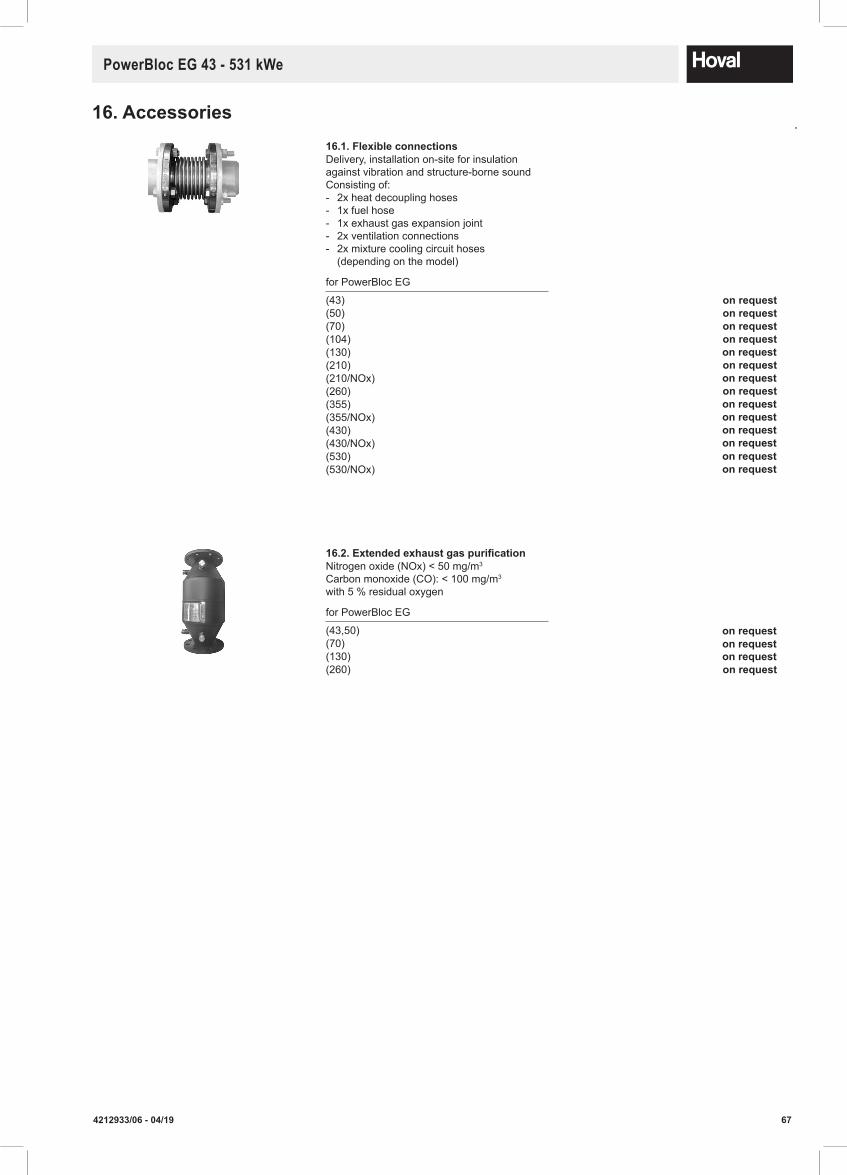
674212933/06 - 04/19
PowerBloc EG 43 - 531 kWe
16.Accessories16.1.FlexibleconnectionsDelivery, installation on-site for insulation against vibration and structure-borne soundConsisting of: - 2x heat decoupling hoses - 1x fuel hose - 1x exhaust gas expansion joint - 2x ventilation connections - 2x mixture cooling circuit hoses
(depending on the model)
for PowerBloc EG
(43)(50)(70)(104)(130)(210)(210/NOx)(260)(355)(355/NOx)(430)(430/NOx)(530)(530/NOx)
16.2.ExtendedexhaustgaspurificationNitrogen oxide (NOx) < 50 mg/m3
Carbon monoxide (CO): < 100 mg/m3
with 5 % residual oxygen
for PowerBloc EG
(43,50)(70)(130)(260) onrequest
onrequest onrequest onrequest onrequest
onrequest
onrequest
onrequest
onrequest
onrequest onrequest
onrequest
onrequest
onrequest
onrequest
onrequest
onrequest onrequest
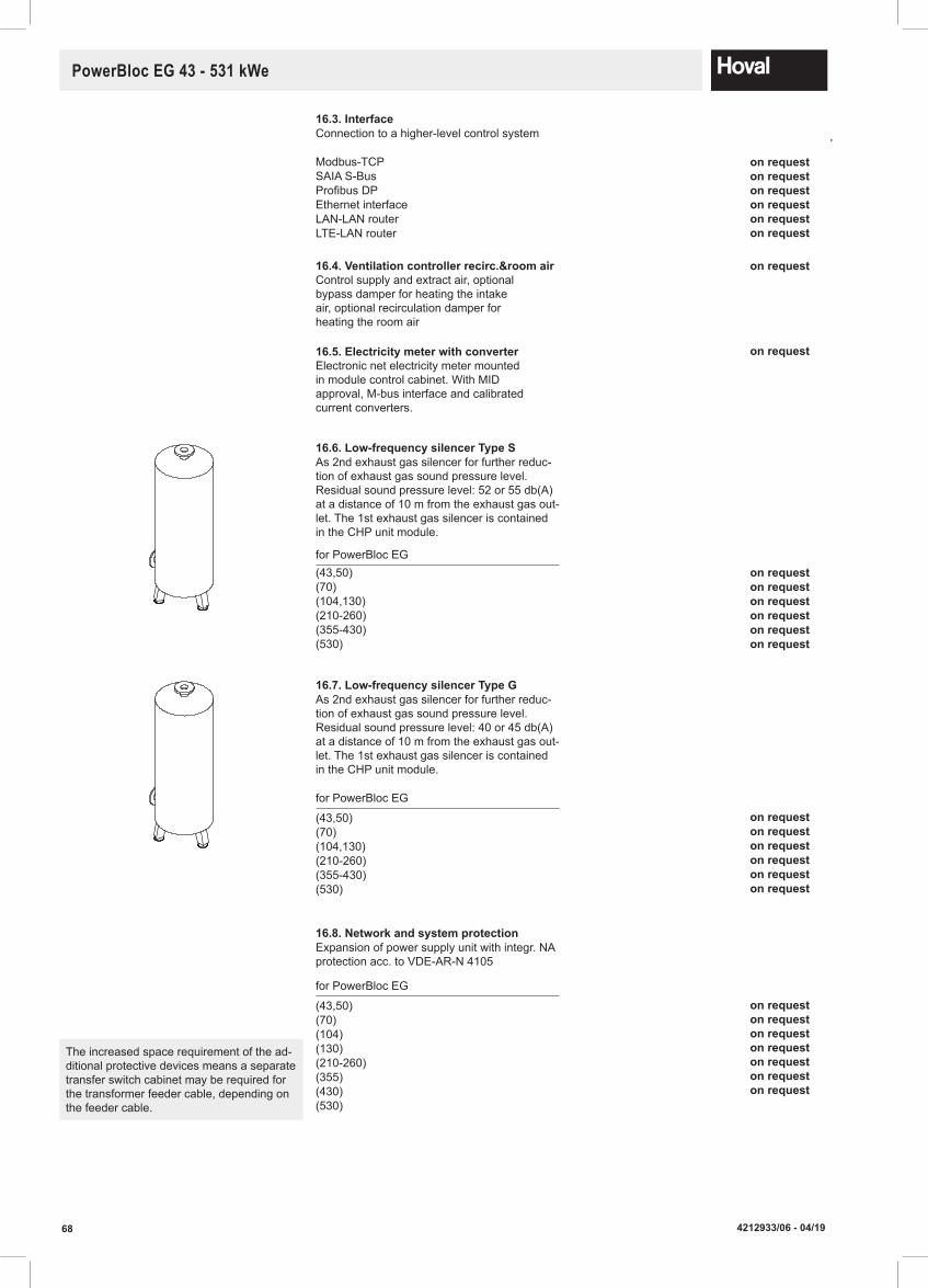
68 4212933/06 - 04/19
PowerBloc EG 43 - 531 kWe
16.3. InterfaceConnection to a higher-level control system
Modbus-TCPSAIA S-BusProfibus DPEthernet interfaceLAN-LAN routerLTE-LAN router
16.6.Low-frequencysilencerTypeSAs 2nd exhaust gas silencer for further reduc-tion of exhaust gas sound pressure level.Residual sound pressure level: 52 or 55 db(A) at a distance of 10 m from the exhaust gas out-let. The 1st exhaust gas silencer is contained in the CHP unit module.
for PowerBloc EG(43,50)(70)(104,130)(210-260)(355-430)(530)
16.7.Low-frequencysilencerTypeGAs 2nd exhaust gas silencer for further reduc-tion of exhaust gas sound pressure level.Residual sound pressure level: 40 or 45 db(A) at a distance of 10 m from the exhaust gas out-let. The 1st exhaust gas silencer is contained in the CHP unit module.
for PowerBloc EG
(43,50)(70)(104,130)(210-260)(355-430)(530)
16.8.NetworkandsystemprotectionExpansion of power supply unit with integr. NA protection acc. to VDE-AR-N 4105
for PowerBloc EG
(43,50)(70)(104)(130)(210-260)(355)(430)(530)
The increased space requirement of the ad-ditional protective devices means a separate transfer switch cabinet may be required for the transformer feeder cable, depending on the feeder cable.
16.4. Ventilation controller recirc.&room air Control supply and extract air, optional bypass damper for heating the intake air, optional recirculation damper for heating the room air
16.5. Electricity meter with converter Electronic net electricity meter mounted in module control cabinet. With MID approval, M-bus interface and calibrated current converters.
onrequest
onrequest
onrequest
onrequest
onrequest
onrequest onrequest onrequest onrequest
onrequest
onrequest
onrequest
onrequest
onrequest
onrequest
onrequest
onrequest
onrequest
onrequest
onrequest
onrequest onrequest
onrequest
onrequest
onrequest
onrequest
onrequest

694212933/06 - 04/19
PowerBloc EG 43 - 531 kWe
16.9.EmergencycoolingFor the emergency cooling circuit, the corre-sponding components (table cooler, pump, heat exchanger, three-way valve and actuator, control included in the module controller) are provided. The on-site installation incl. pipes, insulation and cabling is done on-site acc. to the provided hydraulic and electrical diagrams.
for PowerBloc EG
(43)(50)(70)(104)(130)(210)(210/NOx)(260)(355)(355/NOx)(430)(430/NOx)(530)(530/NOx)
16.10.EmergencypowerfunctionmanualBackup power manual operation (basic position)This comprises the work involved in uprating the module controller for the backup power operation (grid monitoring, etc.). At the client’s the system must be equipped with a corres-ponding mains coupling switch and measu-ring instruments for the module control.
16.11.StainlesssteelcondensationballThe exhaust gas condensation line must be configured acc. to the conditions in the building so no exhaust gas can emerge through this pipe. The stainless steel condensation ball set is installed in the condensation pipe for this purpose.
16.12.GasdetectionsystemGas measuring computer with a gas sensor and connection to the module controller. Prealarm set to 20 % LEL Main alarm set to 40 % LEL integr. relay contacts for alarm message relay contact can be acknowledged for activating a horn (optional), installation by client
16.13.SmokewarningsystemSmoke detector for the CHP unit room battery operation without mains power integr. acoustic warning sound integr. relay contact for alarm message to the module controller, installation by the client
onrequest
onrequest
onrequest
onrequest
onrequest
onrequest
onrequest
onrequest
onrequest
onrequest
onrequest
onrequest
onrequest
onrequest
onrequest
onrequest
onrequest onrequest
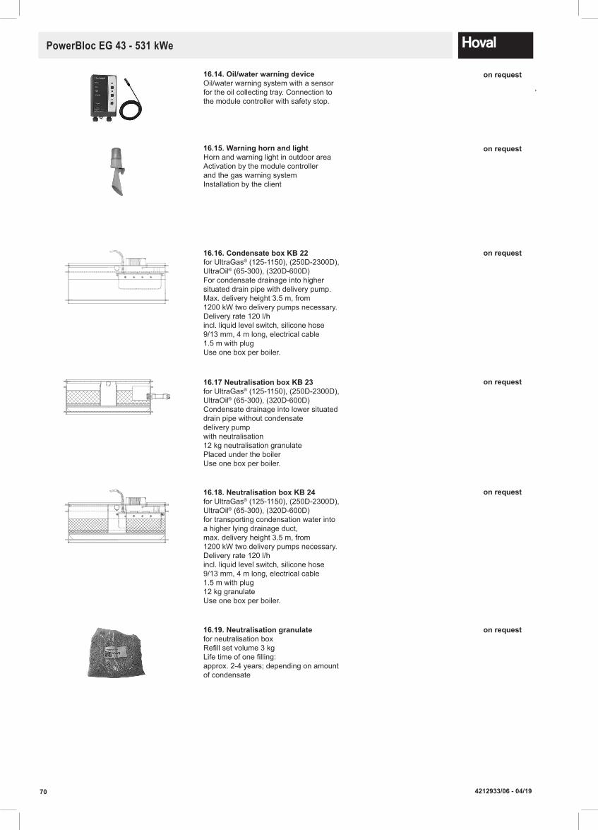
70 4212933/06 - 04/19
PowerBloc EG 43 - 531 kWe
16.14.Oil/waterwarningdeviceOil/water warning system with a sensorfor the oil collecting tray. Connection tothe module controller with safety stop.
16.15.WarninghornandlightHorn and warning light in outdoor area Activation by the module controller and the gas warning systemInstallation by the client
16.16.CondensateboxKB22for UltraGas® (125-1150), (250D-2300D),UltraOil® (65-300), (320D-600D)For condensate drainage into highersituated drain pipe with delivery pump.Max. delivery height 3.5 m, from1200 kW two delivery pumps necessary.Delivery rate 120 l/hincl. liquid level switch, silicone hose9/13 mm, 4 m long, electrical cable1.5 m with plugUse one box per boiler.
16.17NeutralisationboxKB23 for UltraGas® (125-1150), (250D-2300D), UltraOil® (65-300), (320D-600D) Condensate drainage into lower situated drain pipe without condensate delivery pump with neutralisation 12 kg neutralisation granulate Placed under the boiler Use one box per boiler.
16.18.NeutralisationboxKB24for UltraGas® (125-1150), (250D-2300D),UltraOil® (65-300), (320D-600D)for transporting condensation water intoa higher lying drainage duct,max. delivery height 3.5 m, from1200 kW two delivery pumps necessary.Delivery rate 120 l/hincl. liquid level switch, silicone hose9/13 mm, 4 m long, electrical cable1.5 m with plug12 kg granulateUse one box per boiler.
16.19.Neutralisationgranulate for neutralisation box Refill set volume 3 kg Life time of one filling: approx. 2-4 years; depending on amount of condensate
onrequest
onrequest
onrequest
onrequest
onrequest
onrequest

4212
933/
06- A
pril
2019
Responsibiltyforenergyandenvironment
Hoval follows a policy of continued improvement and reserves the right to change specifications without notice.
Technical advice
We are happy to assist you and your planning partners in developing intelligent systems, allowing you to take advantage of our expertise and the experience of our specialists.
After sales
For specialist commissioning and maintenance of your Hoval equipment, contact our service and spares depart-ment.
One-stop shopping
With us you can easily incorporate gas, oil, heat pump, solar, CHP, or biomass energy solutions into your heating system.
Hoval LtdNorthgateNewark-on-TrentNottinghamshireNG24 1JNUnitedKingdom
Phone 01636 672 711Fax 01636 673 [email protected]
Service 01636 593 [email protected]@hoval.com


![Solar [ExA-en] 2016 - Hoval€¦ · T P Hoval solar armature groups Description55 Part No. 56 Technical data 62 Dimensions65 Solar controllers and accessories Solar systems Hoval](https://static.documents.pub/doc/80x56/6076d7ed067e986d61693486/solar-exa-en-2016-hoval-t-p-hoval-solar-armature-groups-description55-part-no.jpg)


