234
Developer Note APPLE CONFIDENTIAL 11/4/92 Developer Technical Publications © Apple Computer, Inc. 1992 Developer Note Macintosh Duo System

Developer Note APPLE CONFIDENTIAL
11/4/92Developer Technical Publications© Apple Computer, Inc. 1992
Developer Note
Macintosh Duo System
Apple Computer, Inc.© 1992, Apple Computer, Inc.All rights reserved. No part of this publication may be reproduced, stored in a retrieval system, or transmitted, in any form or by any means, mechanical, electronic, photocopying, recording, or otherwise, without prior written permission of Apple Computer, Inc. Printed in the United States of America.The Apple logo is a registered trademark of Apple Computer, Inc. Use of the “keyboard” Apple logo (Option-Shift-K) for commercial purposes without the prior written consent of Apple may constitute trademark infringement and unfair competition in violation of federal and state laws. No licenses, express or implied, are granted with respect to any of the technology described in this book. Apple retains all intellectual property rights associated with the technology described in this book. This book is intended to assist application developers to develop applications only for Apple Macintosh computers.
Apple Computer, Inc.20525 Mariani AvenueCupertino, CA 95014408-996-1010
Apple, the Apple logo, APDA, AppleLink, AppleTalk, ImageWriter, LaserWriter, LocalTalk, Macintosh, and MacTerminal are trademarks of Apple Computer, Inc., registered in the United States and other countries.Apple Desktop Bus, Finder, Macintosh Duo, Macintosh Quadra, PowerBook Duo, MacWorkStation, and QuickDraw are trademarks of Apple Computer, Inc.Adobe Illustrator and PostScript are trademarks of Adobe Systems Incorporated, which may be registered in certain jurisdictions.FrameMaker is a registered trademark of Frame Technology Corporation.Helvetica and Palatino are registered trademarks of Linotype Company.ITC Zapf Dingbats is a registered trademark of International Typeface Corporation.MacDraw is a registered trademark of Claris Corporation.NuBus is a trademark of Texas Instruments.Varityper is a registered trademark of Varityper, Inc.
Simultaneously published in the United States and Canada.
LIMITED WARRANTY ON MEDIA AND REPLACEMENT
If you discover physical defects in the manual or in the media on which a software product is distributed, APDA will replace the media or manual at no charge to you provided you return the item to be replaced with proof of purchase to APDA.
ALL IMPLIED WARRANTIES ON THIS MANUAL, INCLUDING IMPLIED WARRANTIES OF MERCHANTABILITY AND FITNESS FOR A PARTICULAR PURPOSE, ARE LIMITED IN DURATION TO NINETY (90) DAYS FROM THE DATE OF THE ORIGINAL RETAIL PURCHASE OF THIS PRODUCT.
Even though Apple has reviewed this manual, APPLE MAKES NO WARRANTY OR REPRESENTATION, EITHER EXPRESS OR IMPLIED, WITH RESPECT TO THIS MANUAL, ITS QUALITY, ACCURACY, MERCHANTABILITY, OR FITNESS FOR A PARTICULAR PURPOSE. AS A RESULT, THIS MANUAL IS SOLD “AS IS,” AND YOU, THE PURCHASER, ARE ASSUMING THE ENTIRE RISK AS TO ITS QUALITY AND ACCURACY.
IN NO EVENT WILL APPLE BE LIABLE FOR DIRECT, INDIRECT, SPECIAL, INCIDENTAL, OR CONSEQUENTIAL DAMAGES RESULTING FROM ANY DEFECT OR INACCURACY IN THIS MANUAL, even if advised of the possibility of such damages.
THE WARRANTY AND REMEDIES SET FORTH ABOVE ARE EXCLUSIVE AND IN LIEU OF ALL OTHERS, ORAL OR WRITTEN, EXPRESS OR IMPLIED. No Apple dealer, agent, or employee is authorized to make any modification, extension, or addition to this warranty.
Some states do not allow the exclusion or limitation of implied warranties or liability for incidental or consequential damages, so the above limitation or exclusion may not apply to you. This warranty gives you specific legal rights, and you may also have other rights which vary from state to state.

Contents
Figures and Tables xi
Preface About This Note xvii
Conventions Used in This Book xviiOther Reference Material xviiiFor More Information xix
Part 1 Macintosh PowerBook Duo Computer 1
Chapter 1 Introduction to the Macintosh PowerBook Duo Computer 3
Software Issues 4Market Segments 4Machine Identification 6PowerBook Duo Features 6Expansion Features 7Design Architecture 7
Processing and Control 7Memory and Storage Capacity 10Communication 10
SCSI and SCC Interface Capabilities 10Modem and Fax Links 11
Human Interface 11Video Display Panel 11Keyboard 11Trackball 11Microphone and Speaker 12
Main Expansion Connector 12
Chapter 2 PowerBook Duo Main Logic Board 13
Main Processor 15Memory Mapping 16Memory 19
DRAM 19DRAM Expansion Card 19
iii

System ROM 19Docking Manager Calls on ROM 20
Main System Controller 20Integrated VIAs 20
Timing and Interrupt Control 21Memory Access and Control 21
Sound DMA 21Power Saving 21
Power Requirements and Management 22The Power Manager 22
Operating Modes 22Power-Saving and Built-in Security Features 24
PowerBook Duo Power States 24Nap 24Sleep 25Shutdown 25
Battery Power Supply and AC Power Adapter 25Power Operating Modes 26Battery Charger 26AC Power Adapter 26
Combination SCSI/SCC Controller Chip 26Small Computer System Interface (SCSI) 26Serial Communication Controller (SCC) 27Power-Management Constraints for SCSI and SCC 27
Video Components 27Sound Components 28
Chapter 3 Internal Hard Disk 29
Hard-Disk Drive Housing 30Operating Modes 33
Power Off Mode 33Start-up Mode 33Ready Mode 33Standby Mode 33
Power Requirements 33Hard Disk Interface 34
Interface Requirements 34SCSI Connector 34Terminator 35
Chapter 4 Input/Output Interfaces 37
Main Expansion Connector 39
iv

Serial Port Connector 43Power Connector 44RJ-11 Modem Connector 45
Chapter 5 Internal Modem 47
Modem Hardware 48Mechanical Specifications 48Modem Implementation for Different Markets 49Telephone Line Interface 52
Software Architecture 53Modem Control Panel 53Communications ToolBox 53Fax Terminal Software 53
FAX Sender 54FAX Extension Driver 54FAX Terminal 54
Compatibility 54Modem Features 54
Communicating with the Modem 55Arbitration 55Ring Messages 56
Data-User Associations 56Non-Data User Associations 56
Error Correction and Data Compression 57Installation 57Fax Send and Receive Capabilities 57Modem Card Power Requirements 58Modem Interface 58
Modem Card Electrical Interface 58Modem Card Hardware Interface 59
Stand-alone PowerBook Duo 59PowerBook Duo with MiniDock 60PowerBook Duo with Duo Dock 60
Modem Power Control Interface 62Telephone Line Electrical Interface 63
Modem/fax Specifications 63
Chapter 6 DRAM Expansion Cards 65
Design Specifications 66DRAM Components 66Apple-designed Cards 66
Addressing the Expansion Cards 69
v

DRAM Expansion Card Interface 69DRAM Expansion Card Current and Power Draw 71DRAM Expansion Card Specifications 72
Chapter 7 Mechanical Features 73
Clamshell Housing 74LCD Panel 74Integral Keyboard 76Integral Trackball 78
Chapter 8 PowerBook Duo Software 79
CPU ROM 80Universal ROM Support 80Mouse/Trackball 80Video Driver 80SCSI Manager 81
Declaration ROM 81System Software 81
PowerBook Control Panel 81Port A AppleTalk 82PowerBook Duo Display Control Panel 83AutoRemounter 83Data Pump Driver 84
Fax Support 84Software Features 85
Part 2 PowerBook Duo Floppy Adapter and Macintosh Duo MiniDock 87
Chapter 9 Introduction to the PowerBook Duo Floppy Adapter and Macintosh Duo MiniDock 89
Overview of the PowerBook Duo Floppy Adapter 91Overview of the Macintosh Duo MiniDock 91Power Budget 92Electrical Considerations 93Thermal Considerations 93
vi

Chapter 10 PowerBook Duo Floppy Adapter Hardware 95
PowerBook Duo Floppy Adapter Housing 96Interface with the PowerBook Duo 96Floppy Adapter Main Logic Board 98Apple Desktop Bus Connector 100Support for Floppy Disk Drive 101Power Supply 102
Chapter 11 Macintosh Duo MiniDock Hardware 103
Designing a Macintosh Duo MiniDock 104Macintosh Duo MiniDock Housing 104
Rear Panel I/O Connectors 105Locking Mechanism 106
Docking Constraints 106Interface with the Powerbook Duo 106Duo MiniDock Main Logic Board 110Support for Video Features 113
Apple VSC ASIC 114Video RAM 114Video Output 114Video Interface 114
Support for Floppy Disk Drive 115SWIM II Controller 115Floppy Disk Drive Interface 116
Support for SCSI Devices 117Serial I/O Support 118Apple Desktop Bus Connector 119Audio Ports 120Declaration ROM 120Power Sources 121Modem Adapter Card 121
Chapter 12 Software Issues for the Floppy Adapter and the MiniDock 123
Docking and Undocking the PowerBook Duo 124Docking Conditions 124Docking Constraints 124
Preferences and Information Identities 126Multiple Environments 127
Monitors 127File-Server Connections 127
vii

Single to Multiple Ports 127Overview of Declaration ROM Functions 128Overview of Modified System ROM Functions 128
Start-Up Process 128Wake-Up Process 129
Part 3 Macintosh Duo Dock 131
Chapter 13 Introduction to the Macintosh Duo Dock 133
Overview of the Macintosh Duo Dock 134
Chapter 14 Macintosh Duo Dock Hardware 137
Declaration ROM 138Docking Constraints 139Macintosh Duo Dock Housing 139PowerLatch Technology 143Interface to the PowerBook Duo 143Duo Dock Main Logic Board 147Video Support 149
Video Subsystem Controller 149Video RAM 151Video Output 153Video Port 153
SCSI Support 154Serial Communication Ports 156Apple Desktop Interface 157Sound Ports 158Modem Adapter Card 158Internal Floppy Drive 160Optional Hard Drive 160NuBus Expansion 162
NuBus Controller 162NuBus Interface 162
Floating-Point Unit Interface 168Power Supply 170Network Support 171
viii
Chapter 15 Software Issues for the Duo Dock 173
Docking and Undocking the PowerBook Duo 174Docking Conditions 174Docking Constraints 175
Preferences and Information Identities 177Multiple Environments 177
Monitors 178File-Server Connections 178AppleTalk 178
Single to Multiple Ports 178Auto-Remounting Support 179Overview of Declaration ROM Functions 179Overview of Modified System ROM Functions 179
Start-Up Process 180Wake-Up Process 180
Appendix A Declaration ROM Specifications 181
Overview 181Firmware Structure 182
Firmware Overview 182The Format Block 182The Board sResource 182The sResource Directory 183The Docking Functional sResource 184
Hardware Attributes 186Docking Attributes 188Locking Attributes 188Power Status 189SCC Ports 190SCSI Disk Mode 191SCSI Chip Type 191NuBus Connectors 192Eject Attributes 193Sound Attributes 193Floppy Drive Icon 194ROM Version 194Base Address Calls 194
Docking Initialization 194Docking Cleanup 195Save Sleep State 195Restore Sleep State 195Docking Eject 196Power Control 196
ix
SCSI Disk Mode Interrupt Handler 197CPU Speed 197Diagnostic Tests 197Docking Slot 197
Other Functional sResources 197The System ROM Process 198
The Start-Up Process 198The Wake-Up Process 198
Duo Dock versus Duo MiniDock 199
Glossary 201
Index 205
x

Figures and Tables
Preface About This Note xvii
Chapter 1 Introduction to the Macintosh PowerBook Duo Computer 3
Figure 1-1 The PowerBook Duo 5Figure 1-2 PowerBook Duo with expansion capabilities 8Figure 1-3 PowerBook Duo simplified block diagram 9
Chapter 2 PowerBook Duo Main Logic Board 13
Figure 2-1 Block diagram of the PowerBook Duo main logic board functions 14
Figure 2-2 Outline of PowerBook Duo main logic board 15Figure 2-3 Physical address space of the PowerBook Duo 17Figure 2-4 Map of I/O space 18Figure 2-5 Map of video buffer and pseudo NuBus expansion space 18Table 2-1 On/off button effects on Power Manager 23
Chapter 3 Internal Hard Disk 29
Figure 3-1 Hard disk drive housing 31Figure 3-2 Bracket for the hard disk drive 32Table 3-1 Hard disk current drain and power consumption 34Table 3-2 Hard disk SCSI connector signal assignments 35
Chapter 4 Input/Output Interfaces 37
Figure 4-1 Rear panel of the PowerBook Duo 38Table 4-1 Main expansion connector signal assignments 39Table 4-2 Serial port connector signal assignments 44Table 4-3 Power connector signal assignments 44
Chapter 5 Internal Modem 47
Figure 5-1 Outline of domestic and international modem cards 49Figure 5-2 Modem card dimensions 50Figure 5-3 Modem card component height 51Figure 5-4 Simplified view of modem card functions 52Table 5-1 Modem card connector signal assignments 58Figure 5-5 Interface between modem card and the PowerBook Duo 60Figure 5-6 Interface between modem card and the Mini Dock 61
xi
Figure 5-7 Interface between modem card and the Duo Dock 62Table 5-2 Modem/fax specifications 63
Chapter 6 DRAM Expansion Cards 65
Figure 6-1 Outline of DRAM expansion card 67Figure 6-2 DRAM expansion card chip configuration 68Table 6-1 Summary of DRAM capacities 68Table 6-2 DRAM expansion card connector signal assignments 69Table 6-3 DRAM expansion card current and power draw 72Table 6-4 DRAM expansion card specifications 72
Chapter 7 Mechanical Features 73
Figure 7-1 View of PowerBook Duo housing in open position 75Figure 7-2 Views of PowerBook Duo housing closed 76Figure 7-3 PowerBook Duo keyboards 77Figure 7-4 PowerBook Duo trackball assembly 78
Chapter 8 PowerBook Duo Software 79
Figure 8-1 The PowerBook Duo control panel 82Figure 8-2 Options dialog box 82Figure 8-3 PowerBook Duo display control panel 83Figure 8-4 AutoRemounter control panel 83
Chapter 9 Introduction to the PowerBook Duo Floppy Adapter and Macintosh Duo MiniDock 89
Figure 9-1 PowerBook Duo with Floppy Adapter and MiniDock features 90Table 9-1 Expansion device power budget 92
Chapter 10 PowerBook Duo Floppy Adapter Hardware 95
Figure 10-1 Views of PowerBook Duo Floppy Adapter 97Table 10-1 Main expansion connector pins used for the Floppy Adapter
interface 98Figure 10-2 Outlines of the PowerBook Duo Floppy Adapter logic board with
components and dimensions 99Figure 10-3 Block diagram of PowerBook Duo Floppy Adapter functions 100Figure 10-4 ADB connector pin designations 100Figure 10-5 Floppy disk drive connector pin designations 101Table 10-2 ADB connector signal assignments 101Table 10-3 Floppy disk drive connector signal assignments 102
xii

Chapter 11 Macintosh Duo MiniDock Hardware 103
Figure 11-1 Macintosh Duo MiniDock housing 105Table 11-1 Main expansion connector signals used for the Duo MiniDock
interface 107Figure 11-2 Macintosh Duo MiniDock logic board with components 111Figure 11-3 Macintosh Duo MiniDock logic board with dimensions 112Figure 11-4 Block diagram of Macintosh Duo MiniDock functions 113Figure 11-5 Video connector pin designations 114Table 11-2 Video formats 114Table 11-3 Video connector signal assignments 115Figure 11-6 Floppy disk drive connector pin designations 116Table 11-4 Floppy disk drive connector signal assignments 116Figure 11-7 SCSI connector pin designations 117Table 11-5 SCSI connector signal assignments 117Figure 11-8 Serial port connector pin designations 119Table 11-6 Serial port connector signal assignments 119Figure 11-9 ADB connector pin designations 120Table 11-7 ADB connector signal assignments 120Table 11-8 Power sources for Macintosh Duo MiniDock subsystems 121Figure 11-10 Modem adapter card 122Table 11-9 Modem adapter card connector signal assignments 122
Chapter 12 Software Issues for the Floppy Adapter and the MiniDock 123
Table 12-1 Conditions for docking and undocking the PowerBook Duo 125Figure 12-1 Disconnect alert box 126Figure 12-2 Connect alert box 126
Chapter 13 Introduction to the Macintosh Duo Dock 133
Figure 13-1 PowerBook Duo with Macintosh Duo Dock features 135
Chapter 14 Macintosh Duo Dock Hardware 137
Figure 14-1 Macintosh Duo Dock with monitor 140Figure 14-2 Side views of Macintosh Duo Dock 141Figure 14-3 Rear and front views of Macintosh Duo Dock 142Table 14-1 Main expansion connector signals used for the Duo Dock
interface 144Figure 14-4 Outline of Macintosh Duo Dock logic board 148Table 14-2 Video formats 149Figure 14-5 Block diagram of Macintosh Duo Dock functions 150Figure 14-6 VRAM SIMM 151Table 14-3 VRAM SIMM connector signal assignments 151Figure 14-7 Video connector pin designations 153Table 14-4 Video connector signal assignments 153Figure 14-8 SCSI connector pin designations 155
xiii

Table 14-5 SCSI connector signal assignments 155Figure 14-9 Serial port connector pin designations 156Figure 14-10 ADB connector pin designations 157Table 14-6 Serial port connector signal assignments 157Table 14-7 ADB connector signal assignments 158Figure 14-11 Modem adapter card 159Table 14-8 Modem adapter connector signal assignments 159Table 14-9 Floppy disk drive connector signal assignments 160Table 14-10 Hard drive 50-pin SCSI connector signal assignments 161Table 14-11 NuBus I/O space 162Figure 14-12 NuBus adapter connector on Macintosh Duo Dock logic
board 163Figure 14-13 NuBus adapter card mounting configuration 163Figure 14-14 Front view of NuBus adapter card showing connectors 164Table 14-12 NuBus adapter card connector signal assignments 164Table 14-13 NuBus adapter card connector signal assignments 166Table 14-14 FPU interface signal assignments 168Table 14-15 DC output currents and power 171Table 14-16 DC output voltage cross-regulation limits 171Table 14-17 Power supply connector signal assignments 171
Chapter 15 Software Issues for the Duo Dock 173
Table 15-1 Conditions for docking and undocking the PowerBook Duo computer 174
Figure 15-1 Sleep alert box 176Figure 15-2 Sleep warning alert box 176Figure 15-3 Computer locked alert box 177
Appendix A Declaration ROM Specifications 181
Figure A-1 Board sResource 183Figure A-2 sResource directory 184Table A-1 Defined selectors 185Figure A-3 Function result dockHardwareAttr 187Table A-2 dockHardwareAttr bit fields. 187Figure A-4 Function result dockDockingAttr 188Table A-3 dockDockingAttr bit fields. 188Figure A-5 Function result dockLockingAttr 189Figure A-6 Function result dockPowerStatus 189
Table A-4 Function result dockLockingAttr bit fields 189Figure A-7 Function result dockSCC Ports 190Table A-5 dockPowerStatus bit fields 190Table A-6 dockSCC Ports bit fields 190Figure A-8 Function result dockSCSIDiskMode 191
Figure A-9 Function result dockSCSIType 191
Table A-7 dockSCSIDiskMode bit fields 191Figure A-10 Function result dockNuBusConnects 192Table A-8 dockSCSIType bit fields 192
xiv

Table A-9 dockNuBusConnects bit fields 192Figure A-11 Function result dockEjectStatus 193Figure A-12 Function result dockSoundAttr 193
Table A-10 dockEjectStatus bit fields 193Table A-11 dockSoundAttr bit fields 194Figure A-13 Params field dockInit 195Table A-12 dockInit fields 195Figure A-14 Params field dockPowerControl 196Table A-13 dockPowerControl bit fields 196
xv

xvi

P R E F A C E
About This Note
The Macintosh Duo System Developer Note describes design features of the Macintosh PowerBook Duo computer, and its accessories: the Macintosh PowerBook Duo Floppy Adapter, the Macintosh Duo MiniDock, and the Macintosh Duo Dock, which enhance the performance and extend the capabilities of the PowerBook Duo.
This note provides you, the hardware or software developer, with the information you need to design hardware and software elements for the system, including interfaces, expansion devices, and application software. This publication assumes you are familiar with the functionality and programming requirements for Apple Macintosh computers.
This developer note consists of three parts and an appendix.
Part 1, “Macintosh PowerBook Duo Computer.”
Part 2, “PowerBook Duo Floppy Adapter and Macintosh Duo MiniDock.”
Part 3, “Macintosh Duo Dock.”
Appendix, “Declaration ROM Specifications.”
It also contains a glossary and an index for the entire book.
Conventions Used in This Book 0
The following visual cues are used throughout this manual to draw attention to certain types of significant information.
W A R N I N G
A warning like this indicates a potential problem that could damage the hardware, cause the software to crash, or cause permanent loss of data.
IMPORTANT
This type of note contains information that is essential for an understanding of the main text and of the PowerBook Duo computer.
NoteThis type of note contains information of general interest.
When new or specialized terms are defined, they appear in boldface . These terms are also defined in the glossary at the back of the book.
xvii
P R E F A C E
Hexadecimal numbers are preceded by a dollar sign ($). For example, the hexadecimal equivalent of the number 16 would be written as $10. All addresses are hexadecimal.
A slash in front of a signal name (/RESET) indicates an active low signal.
The following common abbreviations are used in the book
A distinction is made between boards and cards. Boards are a permanent part of the computer or expansion device, for example the PowerBook Duo main logic board, or the Macintosh Duo MiniDock main logic board. Cards may be inserted into the system, and can be added or exchanged, for example the DRAM expansion card, and the modem card.
PowerBook Duo is alternatively referred to in the text as the computer.
PowerBook Duo Floppy Adapter is alternatively referred to in the text as the Floppy Adapter.
Macintosh Duo MiniDock is alternatively referred to in the text as the MiniDock.
Macintosh Duo Dock is alternatively referred to in the text as the Duo Dock.
Devices in the same categories as the PowerBook Duo Floppy Adapter and Macintosh Duo MiniDock are referred to generically as expansion devices.
Other Reference Material 0
Related documentation includes:
Guide to the Macintosh Family Hardware.
bps bits per second
DRAM dynamic random access memory
K 1024
MB megabyte
Mbit megabit
ms millisecond
µs microsecond
ns nanosecond
kΩ kilohm
mΑ milliamp
µA microamp
pF picofarad
RAM random access memory
VRAM Video RAM
xviii

P R E F A C E
Designing Cards and Drivers for the Macintosh Family,Third Edition.
Inside Macintosh, Volumes I through VI.
Macintosh Classic II, Macintosh PowerBook Family, and Macintosh Quadra Family Developer Notes, APDA publication number #ROI43LL/A.
For More Information 0
APDA is Apple’s worldwide source for over three hundred development tools, technical resources, training products, and information for anyone interested in developing applications on Apple platforms. Customers receive the quarterly APDA Tools Catalog featuring all current versions of Apple development tools and the most popular third-party development tools. Ordering is easy; there are no membership fees, and application forms are not required for most of our products. APDA offers convenient payment and shipping options, including site licensing.
To order products or to request a complimentary copy of the APDA Tools Catalog, contact
APDA Apple Computer, Inc. P.O. Box 319Buffalo, NY 14207-0319
Telephone 800-282-2732 (United States)800-637-0029 (Canada)716-871-6555 (International)
Fax 716-871-6511
AppleLink APDA
America Online APDA
CompuServe 76666,2405
Internet [email protected]
xix


P A R T O N E
Macintosh PowerBook Duo Computer 1


C H A P T E R 1
Figure 1-0Listing 1-0Table 1-0
Introduction to the Macintosh PowerBook Duo Computer 1

C H A P T E R 1
Introduction to the Macintosh PowerBook Duo Computer
The PowerBook Duo computer is a small, lightweight, battery-operated portable computer. It weighs 4.25 pounds, and measures 8.5" x 10.8" x 1.3". Its clamshell design is similar to that of the Macintosh PowerBook family of portable computers.
The PowerBook Duo operates alone as a notebook, or you may use it with a variety of expansion devices that extend the interface and provide the capabilities of a desktop computer. The PowerBook Duo, with its accessories, eliminates the need for a second computer, working equally well in the office or on the road.
The expanded computer comprises
the PowerBook Duo computer
the PowerBook Duo Floppy Adapter
the Macintosh Duo MiniDock
the Macintosh Duo Dock
This chapter provides you with an overview of the PowerBook Duo computer. Figure 1-1 shows several views of the computer.
You will find design information on the PowerBook Duo Floppy Adapter and the Macintosh Duo MiniDock in Part 2 of this developer note, and on the Macintosh Duo Dock in Part 3 of this note.
Software Issues 1
The software issues covered in this developer note include
the declaration ROM, which is located in the expansion devices, and is used by the PowerBook Duo to identify the devices
the system ROM
system software
support for the modem and fax
Chapter 8, “PowerBook Duo Software,” provides further information on these topics.
Market Segments 1
The target market for the PowerBook Duo includes
users who want to have their files with them at all times: in the office, at home, and when traveling
companies who cannot justify more than one computer per person
users who want to use a full-size color monitor and keyboard at their desks, have access to networks, and NuBus expansion capability
4 Software Issues

C H A P T E R 1
Introduction to the Macintosh PowerBook Duo Computer
Figure 1-1 The PowerBook Duo
users who do not want the trouble of continually connecting and disconnecting cables
users who want to connect custom expansion devices to their portable computers
These needs cross all Apple computer market segments. However, they tend to apply most to customers who have some experience with computers.
Top down view of PowerBook Duo housing Bottom view of PowerBook Duo housing
PowerBook Duo open
Market Segments 5
C H A P T E R 1
Introduction to the Macintosh PowerBook Duo Computer
Machine Identification 1
Using the Gestalt Manager, you can determine whether your application is running on a PowerBook Duo, or another Macintosh model. The machine code for the PowerBook Duo is 32.
PowerBook Duo Features 1
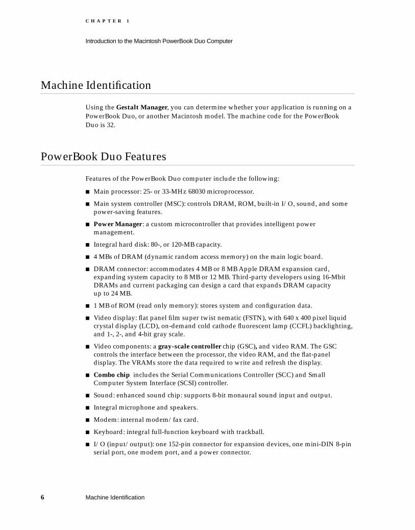
Features of the PowerBook Duo computer include the following:
Main processor: 25- or 33-MHz 68030 microprocessor.
Main system controller (MSC): controls DRAM, ROM, built-in I/O, sound, and some power-saving features.
Power Manager : a custom microcontroller that provides intelligent power management.
Integral hard disk: 80-, or 120-MB capacity.
4 MBs of DRAM (dynamic random access memory) on the main logic board.
DRAM connector: accommodates 4 MB or 8 MB Apple DRAM expansion card, expanding system capacity to 8 MB or 12 MB. Third-party developers using 16-Mbit DRAMs and current packaging can design a card that expands DRAM capacity up to 24 MB.
1 MB of ROM (read only memory): stores system and configuration data.
Video display: flat panel film super twist nematic (FSTN), with 640 x 400 pixel liquid crystal display (LCD), on-demand cold cathode fluorescent lamp (CCFL) backlighting, and 1-, 2-, and 4-bit gray scale.
Video components: a gray-scale controller chip (GSC), and video RAM. The GSC controls the interface between the processor, the video RAM, and the flat-panel display. The VRAMs store the data required to write and refresh the display.
Combo chip includes the Serial Communications Controller (SCC) and Small Computer System Interface (SCSI) controller.
Sound: enhanced sound chip: supports 8-bit monaural sound input and output.
Integral microphone and speakers.
Modem: internal modem/fax card.
Keyboard: integral full-function keyboard with trackball.
I/O (input/output): one 152-pin connector for expansion devices, one mini-DIN 8-pin serial port, one modem port, and a power connector.
6 Machine Identification
C H A P T E R 1
Introduction to the Macintosh PowerBook Duo Computer
Expansion Features 1
You may use the PowerBook Duo with any of the following expansion devices:
The PowerBook Duo Floppy Adapter, which provides a 20-pin HDI connection for an external floppy drive, and a mini-DIN 4-pin ADB (Apple Desktop Bus) connector.
The Macintosh Duo MiniDock, which provides a 20-pin HDI connection for an external floppy drive, a mini-DIN 4-pin ADB connector, a 30-pin HDI SCSI connector for an external SCSI device, a DB-15 external video connector, a modem adapter, power connector, sound input and output connectors, and two mini-DIN 8-pin serial ports. The Macintosh Duo MiniDock supports 12- to 16-inch monitors, up to 8 bits per pixel.
The Macintosh Duo Dock, which turns the PowerBook Duo portable computer into a a full desk-top computer with enhanced graphics capabilities. It contains a built-in floppy drive, and an internal 50-pin SCSI connector and power connector for an optional built-in 3.5” SCSI hard disk. External connections include a mini-DIN 4-pin ADB connector, a 30-pin HDI SCSI connector for an external SCSI device, a modem connector, power and phone jacks, and two mini-DIN 8-pin serial ports. The Duo Dock supports 12- to 16-inch monitors, up to 16 bits per pixel; has two slots for NuBus cards; and supports an optional 68882 math coprocessor (floating-point unit).
Figure 1-2 on the next page summarizes the PowerBook Duo’s expanded capabilities. For further information about the Floppy Adapter, MiniDock, and Duo Dock, you should refer to Part 2 and Part 3 of this developer note.
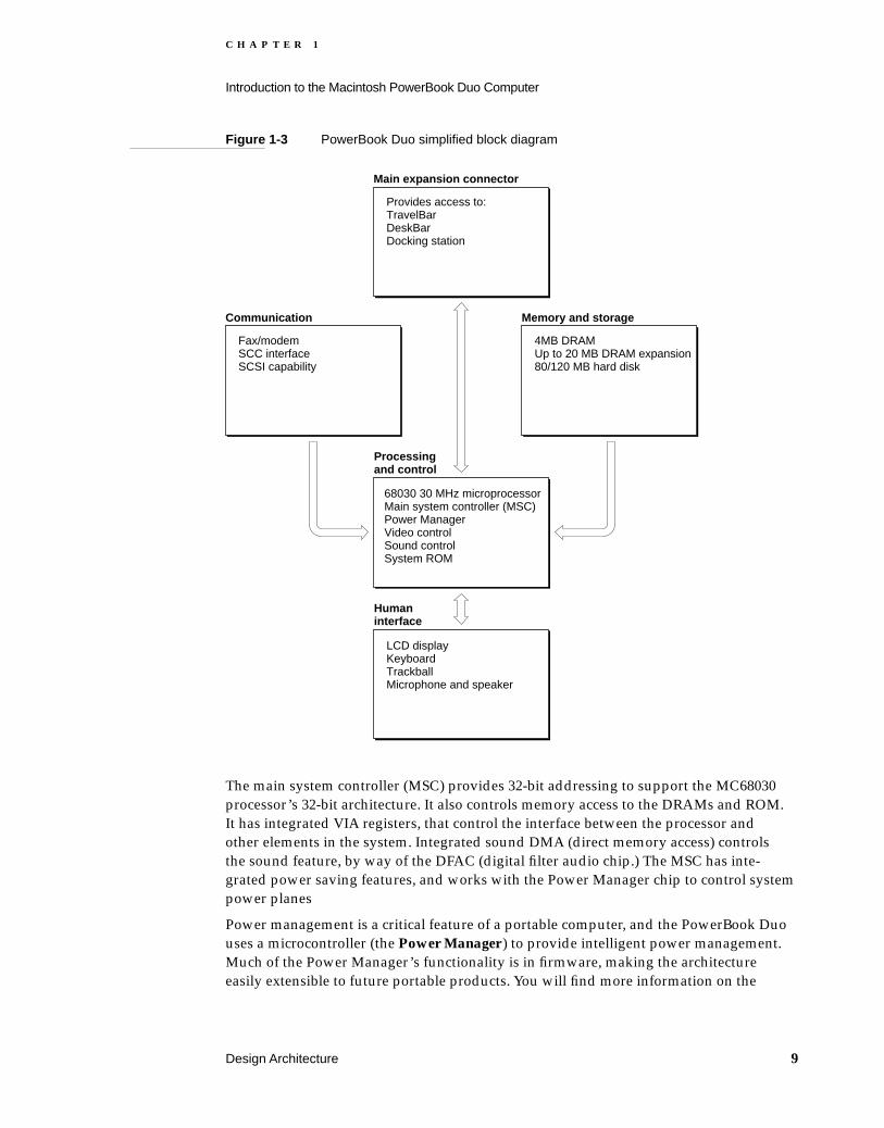
Design Architecture 1
This section gives an overview of the PowerBook Duo computer architecture. Figure 1-3 (on page 9) is a high-level functional block diagram of the computer.
Processing and Control 1The PowerBook Duo computer is designed around the MC68030 microprocessor. This device has complete 32-bit, non-multiplexed, address and data buses. It has sixteen 32-bit general purpose data and address registers, as well as two special-purpose registers, and two registers for stack pointers. The 256-byte instruction cache and the 256-byte data cache can be accessed at the same time. Dynamic bus sizing supports 8-, 16-, and 32-bit memories and peripherals. The MC68030 microprocessor also supports coprocessors with the MC68000 interface, including IEEE floating-point support provided by the MC68881/MC68882. Object code for the processor is fully compatible with that of the MC68020 and earlier devices.
Expansion Features 7

C H A P T E R 1
Introduction to the Macintosh PowerBook Duo Computer
Figure 1-2 PowerBook Duo with expansion capabilities
Macintosh PowerBook Duo
ProcessorMain system controllerSCC interfacePower supplyInternal hard disk (80/120 MB)SoundModem/faxSCSI/SCC Combo chip4 MB integral DRAM4-8 MB Apple DRAM expansion cardsUp to 20 MB third-party expansion cardsPower managementLCD display and controllerKeyboardTrackball1 MB ROM
Macintosh Duo Dock
Internal 1.4 M floppy driveVideo support for 12"-16" monitorsSlots for two NuBus cardsMacintosh I/O- External HD-30 SCSI connector- 2 serial ports- ADB port- Mono sound in, mono sound out- On/off68882 math coprocessor (optional)SCSI connector for internal hard disk (optional)Modem adaptor cardBuilt-in speakerAC convenience outlet for monitor powerPowerLatch technology- Motorized inject/eject- Mechanical lock- Firmware support- System support512K VRAM standard512K VRAM SIMM (optional)128K declaration ROM
152-pin connector
152-pin connector
HDI-20 for external floppy driveDIN 4 ADB connectorModem adapter cardSupports 12-16" monitorsPower and sound connectors2 serial portsSCSI connector for external deviceSCSI/SCC Combo chip512K VRAM128K declaration ROMOn/off button
HDI-20 for external floppy driveDIN 4 ADB connectorSWIM II for floppy control
PowerBook Duo Floppy Adapter Macintosh Duo MiniDock
152-pin connector
152-pin connector
152-pin connector
8 Design Architecture
C H A P T E R 1
Introduction to the Macintosh PowerBook Duo Computer
Figure 1-3 PowerBook Duo simplified block diagram
The main system controller (MSC) provides 32-bit addressing to support the MC68030 processor’s 32-bit architecture. It also controls memory access to the DRAMs and ROM. It has integrated VIA registers, that control the interface between the processor and other elements in the system. Integrated sound DMA (direct memory access) controls the sound feature, by way of the DFAC (digital filter audio chip.) The MSC has inte-grated power saving features, and works with the Power Manager chip to control system power planes
Power management is a critical feature of a portable computer, and the PowerBook Duo uses a microcontroller (the Power Manager ) to provide intelligent power management. Much of the Power Manager’s functionality is in firmware, making the architecture easily extensible to future portable products. You will find more information on the
Main expansion connector
Provides access to:TravelBarDeskBarDocking station
68030 30 MHz microprocessorMain system controller (MSC)Power ManagerVideo controlSound controlSystem ROM
Communication
Fax/modemSCC interfaceSCSI capability
Processing and control
Memory and storage
4MB DRAMUp to 20 MB DRAM expansion80/120 MB hard disk
LCD displayKeyboardTrackballMicrophone and speaker
Human interface
Design Architecture 9

C H A P T E R 1
Introduction to the Macintosh PowerBook Duo Computer
Power Manager and its functions in the section “Power Requirements and Management” in Chapter 2, “PowerBook Duo Main Logic Board.”
The gray-scale controller (GSC) controls the interface between the flat panel display, the video RAM and the processor. You will find more information on video control in the section “Video Components” in Chapter 2, “PowerBook Duo Main Logic Board.”
The PowerBook Duo sound system uses the main memory for the sound buffer. Sound logic on the MSC accesses this memory. In addition to sound playback and recording, the PowerBook Duo provides sound input for recording sounds digitally, and a playthrough feature that permits an external audio source to be mixed with computer-generated sound, and played out through the speaker or headphone jack. The analog processing functions for the sound system are implemented by an application specific IC (ASIC) called the digital filter audio chip (DFAC). You will find more information on this topic in the section “Sound Components” in Chapter 2, “PowerBook Duo Main Logic Board.”
The PowerBook Duo runs system software housed in the System ROM. Chapter 8, “PowerBook Duo Software,” provides further information on this subject.
Memory and Storage Capacity 1PowerBook Duo DRAM capacity is 4 MBs on the main logic board. An expansion connector accommodates 4MB or 8MB Apple DRAM expansion cards, providing a potential 8 or 12 megabytes of DRAM. Using 16-megabit DRAMs, and the current industry packaging scheme, third-party developers can design expansion cards that expand total memory capacity up to 24 MB. Using a special packaging design (described in more detail in Chapter 6, “DRAM Expansion Cards”) not yet qualified by Apple, it is theoretically possible to extend capacity to 32 megabytes. There is one megabyte of read only memory (ROM). The system has an integral hard disk with 80- or 120-MB capacity. It uses memory-mapped I/O, mapping each peripheral I/O device to its own block of processor memory.
These subjects are described in more detail in the section “Memory” in Chapter 2, “PowerBook Duo Main Logic Board,” and in Chapter 3, “Internal Hard Disk.”
Communication 1The PowerBook Duo supports AppleTalk and LocalTalk protocols, through its SCC port. It also has integral modem and fax capabilities.
SCSI and SCC Interface Capabilities 1
The Apple Small Computer System Interface (SCSI) bus is used to daisy-chain SCSI devices to Apple personal computers. The Serial Communications Controller (SCC) controls one serial port that may be programmed for synchronous, asynchronous, or AppleTalk protocols. The SCSI and SCC functions are handled by a single chip called the combo chip. This integration, while conserving physical space on the main logic board, is transparent to the software.
10 Design Architecture

C H A P T E R 1
Introduction to the Macintosh PowerBook Duo Computer
IMPORTANT
Since there is only one serial port, and that port can be used for LocalTalk, compatibility problems may arise.
Modem and Fax Links 1
Communications features are a vital part of this portable machine. The PowerBook Duo must be able to support local area networking and wide-area wired connectivity. Built-in LocalTalk satisfies the need for medium-speed LAN (local area network), and wired connectivity is provided in the form of a PSTN (public switch telephone network) modem.
In the interests of cost and layout flexibility, the modem card is plugged directly into the main logic board. Two versions of the modem card are available. The domestic version, with integral DAA (data access arrangement), is used in the United States, Canada, and Japan. The international version is used in all other overseas countries. It has a discrete DAA that can be changed to suit different telephone systems, without changing the modem card, or the PowerBook Duo main logic board.
The modem provides full-duplex and asynchronous data operation, supporting all popular standards up to V.32 bis (14000 bps). It also supports facsimile (fax) transmission and reception. The modem supports error-detection and error-correction protocols, and data-compression algorithms. Chapter 5, “Internal Modem,” deals with this subject in more detail.
Human Interface 1You can interact with the PowerBook Duo through the video display, keyboard, trackball, microphone, and speaker.
Video Display Panel 1
The video display is a flat panel film super twist nematic (FSTN) display. It provides a 640 x 400 pixel liquid crystal display (LCD), with on-demand cold cathode fluorescent lamp (CCFL) backlighting, and 1-, 2-, or 4-bit gray scale. The section “LCD Panel” in Chapter 7, “Mechanical Features,” provides more information on this subject.
Keyboard 1
The keyboard is an integral part of the PowerBook Duo. It is available in two configurations: U.S. and International. The section “Integral Keyboard” in Chapter 7, “Mechanical Features,” provides additional information.
Trackball 1
The trackball is located in the center of the keyboard. It fulfills the functions of a mouse. The section “Integral Trackball” in Chapter 7, “Mechanical Features,” provides further information.
Design Architecture 11

C H A P T E R 1
Introduction to the Macintosh PowerBook Duo Computer
Microphone and Speaker 1
The PowerBook Duo computer has a microphone input jack for sound input and output, and a built-in speaker. The section “Sound Components” in Chapter 2, “PowerBook Duo Main Logic Board,” provides more information on this subject.
Main Expansion Connector 1
A 152-pin connector on the main logic board allows expansion devices such as the PowerBook Duo Floppy Adapter, Macintosh Duo MiniDock, and Macintosh Duo Dock to be interfaced to the PowerBook Duo, and gives them direct access to the system’s address, data, and control signals. See Chapter 4, “Input/Output Interfaces,” for more information.
12 Main Expansion Connector

C H A P T E R 2
Figure 2-0Listing 2-0Table 2-0
PowerBook Duo Main Logic Board 2
C H A P T E R 2
PowerBook Duo Main Logic Board
This chapter describes the main elements on the PowerBook Duo main logic board, and closely related subjects. Topics covered in this chapter include:
main processor
memory mapping
memory - DRAM and DRAM expansion
system ROM
main system controller (MSC)
power requirements and power management
combination SCSI/SCC controller chip
video components
sound components
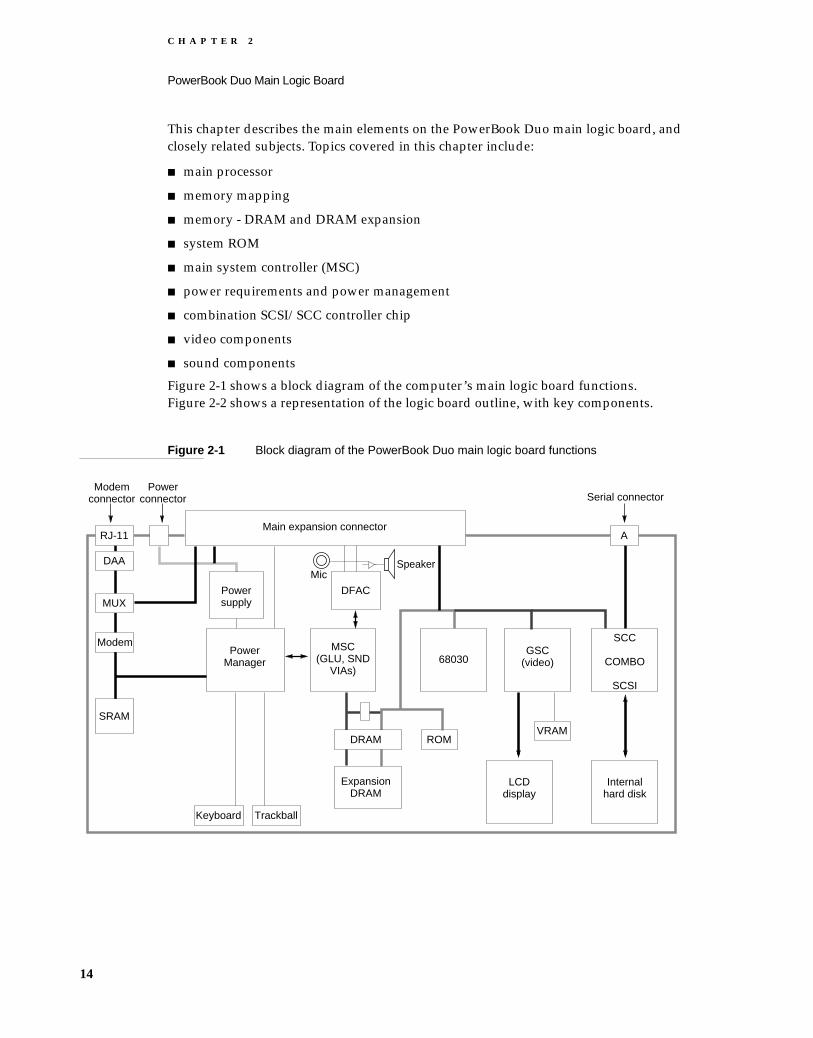
Figure 2-1 shows a block diagram of the computer’s main logic board functions. Figure 2-2 shows a representation of the logic board outline, with key components.
Figure 2-1 Block diagram of the PowerBook Duo main logic board functions
RJ-11
DAA
MUX
Modem
SRAM
Main expansion connectorA
Serial connectorPower
connectorModem
connector
Powersupply
DFAC
MSC(GLU, SND
VIAs)68030
GSC(video)
SCC
COMBO
SCSI
VRAM
LCDdisplay
Internalhard disk
ROM
SpeakerMic
Keyboard Trackball
DRAM
ExpansionDRAM
PowerManager
14

C H A P T E R 2
PowerBook Duo Main Logic Board
Figure 2-2 Outline of PowerBook Duo main logic board
Main Processor 2
The main processor is an MC68030 microprocessor. The 32-bit architecture of this device supports separate 32-bit buses for address and data. The 32-bit address bus provides a 4-gigabyte logical and physical address range. Dynamic bus sizing supports 8-, 16-, and 32-bit memories and peripherals.
The processor’s 32-bit register set consists of 16 general-purpose registers, two super- visor stack pointers, and 10 special-purpose registers. The 256-byte on-chip caches (one for data and one for instructions) can both be accessed at the same time. Pipelined architecture allows access to the internal caches in parallel with bus transfers. The bus controller supports asynchronous, synchronous, and data-burst transfers. The MC68030 supports the MC68881 and MC68882 floating-point coprocessors.
DRAMexpansionconnector
Keyboardconnectors
Test
TrackballBackupbattery
Harddrive
Connectors
Modemexpansionconnector
Serial portconnector
Poweradapter
PowerManager MSC
Combo
Transformer TransformerMC68030processor
ROM
VRAMGSC
DFAC
DRAM array
Displayconnector
152-pin main expansion connector
Main Processor 15

C H A P T E R 2
PowerBook Duo Main Logic Board
For detailed information about the MC68030 microprocessor used in the PowerBook Duo, refer to The Enhanced 32-Bit Microprocessor User’s Manual.
Memory Mapping 2
The PowerBook Duo implements 32-bit memory address-mapping. Memory mapping is the process of translating a logical memory address into an arbitrary physical address. Mapping is essential in a complex, multi-user, multi-task environment, since it allows each program or task to be assigned a separate logical address space, and prevents one task from interfering with another. Mapping is performed on large blocks of addresses by the memory management unit (MMU), which contains tables that map logical memory locations to physical memory locations. MMU functions are integral to the 68030 processor.
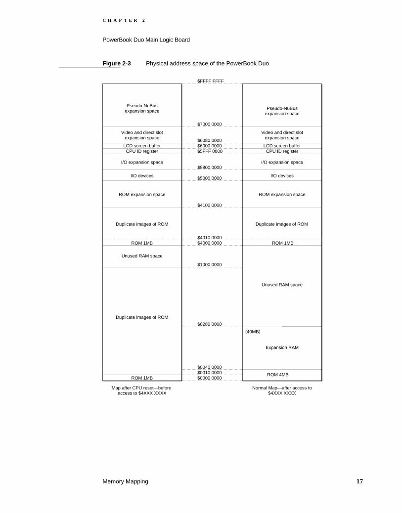
Figure 2-3 shows an overview of the physical address space of the PowerBook Duo.
Figure 2-4 on page 18 is a detailed map of the I/O space. Figure 2-5 on page 18 shows space allocated to the video buffer and for pseudo-NuBus expansion.
16 Memory Mapping
C H A P T E R 2
PowerBook Duo Main Logic Board
Figure 2-3 Physical address space of the PowerBook Duo
Pseudo-NuBusexpansion space
Video and direct slotexpansion space
LCD screen bufferCPU ID register
I/O expansion space
I/O devices
ROM expansion space
Duplicate images of ROM
Pseudo-NuBusexpansion space
Video and direct slotexpansion space
LCD screen bufferCPU ID register
I/O expansion space
I/O devices
ROM expansion space
Unused RAM space
$FFFF FFFF
$7000 0000
$6080 0000$6000 0000$5FFF 0000
$5800 0000
$5000 0000
$4100 0000
$4010 0000$4000 0000
$1000 0000
$0280 0000
$0040 0000$0010 0000$0000 0000
Map after CPU reset—before access to $4XXX XXXX
Normal Map—after access to$4XXX XXXX
Duplicate images of ROM
ROM 1MB
Unused RAM space
ROM 1MB
Duplicate images of ROM
ROM 1MB
ROM 4MB
Expansion RAM
(40MB)
Memory Mapping 17

C H A P T E R 2
PowerBook Duo Main Logic Board
Figure 2-4 Map of I/O space
Figure 2-5 Map of video buffer and pseudo NuBus expansion space
$6000 0000CPU ID
Expansion I/O space
Factory test space
Expansion I/O space
Reserved for AppleReserved for repeated imagesof $5000 0000 to $500F FFFF
Reserved for Apple
Sleep register
Reserved for Apple
AIVReserved for Apple VDAC
Reserved for AppleGSC gray scale
Reserved for AppleSWIM/SWIM II
SoundSCSI (pseudo-DMA) without /DRQ
SCSI (normal mode)Reserved for Apple
SCSI (pseudo-DMA) with /DRQSCC
Reserved for Apple (VIA2)VIA 1
MSC provides/DSACK0
$5FFF 0000
$5900 0000
$5800 0000
$5200 0000
$5010 0000
$500A 2000
$500A 0000
$5002 8000
$5002 6000
$5002 4000
$5002 2000
$5002 0000
$5001 8000
$5001 6000
$5001 4000
$5001 2000
$5001 0000
$5000 8000
$5000 6000
$5000 4000
$5000 2000
$5000 0000
MSC providesno /DSACK0
MSC provides/DSACK0
MSC providesCHIP SELECT only
MSC provides/DSACK0
MSC provides/DSACK0
MSC provides/DSACK0
No device assigned
NuBus super slot expansion space
Direct slot expansion
128K bytes
$FFFF FFFF
$F100 0000
$F000 0000
$7000 0000
$6800 0000
$6080 0000
$6002 0000$6000 0000
NuBus slot expansion space
Video expansion
LCD screen buffer
18 Memory Mapping
C H A P T E R 2
PowerBook Duo Main Logic Board
Memory 2
This section deals with memory requirements for the PowerBook Duo. It describes DRAM requirements, DRAM expansion capabilities, system ROM specifications, and bar declaration ROM interaction with the system ROM.
DRAM 2The PowerBook Duo has four megabytes of DRAM on the main logic board. The low- power, self-refreshing DRAMs are arranged in dual two-megabyte banks. They have an access time of 70 nanoseconds with the 33Mhz microprocessor, and 80ns with the 25Hz microprocessor. Both banks are hard soldered to the main logic board. A typical DRAM bank contains four 512K x 8-bit DRAMs, providing two megabytes of basic memory.
The address map for the DRAM is stored in the MMU. Memory sizing software calculates what banks of RAM are in use, gives the size of each bank, and combines the segments in the table, so that the operating system sees contiguous blocks of memory. More information on memory mapping is provided earlier in this chapter, in the section “Memory Mapping.”
DRAM Expansion Card 2The main logic board has an expansion slot that accommodates the memory expansion card. The one designed by Apple is a plug-in unit with space for 16 DRAMs. The card plugs into the side of the main logic board, and extends memory capacity by 4 or 8 megabytes. This card is described in detail in Chapter 6, “DRAM Expansion Cards.” Using 16 megabit DRAMs, third-party developers can design memory expansion cards that expand total DRAM capacity up to 24 megabytes.
System ROM 2The PowerBook Duo toolbox is stored in a one-megabyte read-only memory (ROM). This ROM also contains information about the machine, including base address space, initialization VIA, NuBus configuration, DRAM arrangement, and CPU identification register.
The PowerBook Duo system ROM has been modified to allow the memory management unit (MMU) table to be set up for the PowerBook Duo’s new address map. This table contains addresses for items such as ROM, video RAM, and the expansion device’s declaration ROM.
Memory 19
C H A P T E R 2
PowerBook Duo Main Logic Board
Docking Manager Calls on ROM 2PowerBook Duo architecture allows you to add hardware features to the computer by means of expansion devices, such as the PowerBook Duo Floppy Adapter, the Macintosh Duo MiniDock, and the Macintosh Duo Dock. These devices connect to the 152-pin connector on the rear panel of the computer. When any expansion device is attached, pin 114 on the main expansion connector is grounded out, and this alerts the computer to the presence of an expansion device.
The logic boards of expansion devices such as the Macintosh Duo MiniDock and the Macintosh Duo Dock contain a declaration ROM. It provides the mechanism to identify the type of expansion device, to describe the data structures, and to provide a programmable interface. It allows the user to attach the expansion device without using configuration switches or special software. The declaration ROM also provides new device drivers and routines that are used by the system ROM. This means the system ROM need not be aware of each and every type of configuration.
The Apple PowerBook Duo Floppy Adapter does not have a declaration ROM. Absence of the declaration ROM when pin 114 is grounded implies the presence of an Apple PowerBook Duo Floppy Adapter.
NoteSome Apple documents refer to the declaration ROM as the configuration ROM.
The Appendix, “Declaration ROM Specifications,” provides detailed information on the declaration ROM.
Main System Controller 2
The main system controller (MSC) supports the 32-bit system processor. It controls the SCC and SCSI input/output, and works in conjunction with the Power Manager to control the computer’s power saving function. Certain MSC functions are addressed as peripheral I/O devices, occupying addresses in the range of $5000 0000 through $5FFF FFFF, as shown in Figure 2-3.
Integrated VIAs 2The MSC’s VIA (versatile interface adapter) registers control the interface between the processor and other elements in the CPU. Some of the VIA registers are of historical interest only and are not used in the PowerBook Duo configuration. Data written to or read from these historical locations is invalid.
20 Main System Controller

C H A P T E R 2
PowerBook Duo Main Logic Board
Timing and Interrupt Control 2
Certain registers control interrupts and enable the software to determine the source of different levels of interrupts.
The registers also control timing and clock inputs to the Combo chip for the SCC interface, and to the GSC flat-panel display controller.
Memory Access and Control 2
The MSC supports up to eight banks of 512K x 8 DRAMs, or four banks of 512K x 8 DRAMs and four banks of 2M x 8 DRAMs. The MSC also controls the ROM and VSRAM (video static RAM) used in the computer. The VIA2 RAM configuration register determines how much RAM is installed in each bank. The software uses the information to select the RAM addressing scheme that places an image of the sound FIFO at the top of the physical address space for the installed RAM. RAM banks 0–3 always appear in the same fixed address spaces. Banks 4–7 change, depending on whether 512K x 8, or 2M x 8 banks are installed.
The MSC generates read and write timing for the serial ports. It also controls SCSI access protocols, and generates read and write timing for accesses, with or without handshaking.
Sound DMA 2The MSC controls a number of functions for the PowerBook Duo sound system. It translates each CPU access to the Sound FIFO register into a RAM access, using the FIFO pointer to generate the RAM address. The MSC monitors the status of the sound FIFO. It also controls sound volume by means of the Sound Volume register, with all 1's producing the highest volume, and all 0’s the lowest.
The MSC’s Sound Clock Rate register sets the standard Macintosh clock rate of 22.25454 kHz, which is derived from the 15.6672 MHz clock. The Sound Record/Play register specifies the sample rate to be used for record or play mode. The MSC also controls a hardware handshake between the processor and the digital filter audio chip (DFAC).
Power Saving 2The system software uses the MSC to conserve power when the computer is running on battery. With the appropriate register configuration, the MSC prepares the computer to enter the sleep state or the nap state. These functions of the MSC are dealt with in more detail in the section “Power Requirements and Management.”
Main System Controller 21

C H A P T E R 2
PowerBook Duo Main Logic Board
Power Requirements and Management 2
The PowerBook Duo’s power management feature is known as EverWatch. It is made up of the following hardware, firmware, and software elements:
The Power Manager, a custom microcontroller, that controls all other power functions, including modem power control, battery monitoring and charging, sequencing for the hard disk, screen and backlight control for the video display panel, parameter RAM control, keyboard scanning, quadrature encoding for trackballs, DFAC control, the real-time clock, Apple Desktop Bus mastership, generation of a 1-Hz clock, and miscellaneous interrupts.
The main system controller (MSC), which controls power to the CPU and to the sound system.
The static RAM which stores the Power Manager’s operating system, and the code executed by the device.
Supporting software code.
The Power Manager 2The 68HC05 Power Manager is an Apple custom chip. Its operating system resides primarily in the external SRAM. However, the Power Manager also contains 512 bytes of internal masked ROM. This ROM provides the functionality to load the code needed to program the SRAM from the system, and also fully supports the Power Manager when it is operating in low-power modes. Much of the Power Manager’s functionality is in firmware, making the architecture easily extensible to future portable products.
The Power Manager communicates with the main processor using a six-wire, serial, interface.
Operating Modes 2
The Power Manager operates in many different modes to maximize performance and functionality, while minimizing current draw. To the outside world, there are three basic modes: full-power run, shutdown, and sleep.
Implementing the Modes 2
The device runs in full-power run mode whenever the computer is active.
The Power Manager shuts down the computer under the following conditions:
If the battery gets low.
If the software requests a shutdown.
If you select Shutdown in the Finder, to implement an orderly shutdown, or to restart the computer.
22 Power Requirements and Management

C H A P T E R 2
PowerBook Duo Main Logic Board
If you press the on/off button on the rear panel of the PowerBook Duo. The state implemented by the on/off button depends upon the state that exists when you depress the button. Table 2-1 summarizes the different effects of the on/off button. (The impact of the on/off button on the PowerBook Duo computer is precisely the same as its impact on the Power Manager.)
W A R N I N G
If you use the on/off button to implement a shutdown, you will get an immediate shutdown, and any applications running will not have time to close and save files.
NoteYou may reset the PowerBook Duo by holding down the Control and Command keys, and pressing the Power On key on the keyboard. This method of resetting is a useful alternative to using the on/off button if you have a software hang up.
The Macintosh operating system selects sleep mode under the following conditions:
If the computer is idle for a given time, up to a maximum of 30 minutes. You may select the length of the idle period, using the PowerBook Control Panel shown in Chapter 8, “Software Issues,” Figure 8-1.
If you close the clamshell housing.
If you request sleep using the Finder menu.
Coming Out of Sleep or Shutdown 2
You can bring the Power Manager and the PowerBook Duo out of shutdown or sleep states in a number of ways:
You can press the on/off button on the rear panel of the PowerBook Duo, and if the computer is shutdown or asleep, it will come on. (See Table 2-1).
If the computer is asleep, you can waken it by holding down any key on the keyboard.
You can set the automatic wake-up feature in the PowerBook Control panel.
NoteMoving the trackball, or pressing its button, does not wake up the computer from either shutdown or sleep mode.
Table 2-1 On/off button effects on Power Manager
Action taken Current state New state
Press on/off button
Shutdown On
Sleep On
On Shutdown
Power Requirements and Management 23
C H A P T E R 2
PowerBook Duo Main Logic Board
Power-Saving and Built-in Security Features 2
The Power Manager has many built-in features that minimize power consumption, while at the same time ensuring computer reliability and safety.
The Power Manager has a hardware feature, known as the computer operating properly (COP) watchdog feature. Using COP, the Power Manager provides an address which must be written to in a specific way at least once every four seconds. If this write operation does not occur, a full Power Manager reset takes place. This feature guarantees that batteries will not be incorrectly charged for an extended period of time, even if the firmware crashes.
The Power Manager is clocked by an external 32kHz signal, and internally derives a 4 MHz clock by means of a phase-locked loop. This feature is selected through the software, so that the operating system can decide when it needs full-speed operation, and when it can manage with slow speed. Slow-speed operation is selected typically before a stop instruction is executed, and full speed is restored when the Power Manager exits from stop mode.
The Power Manager also has a stop instruction, which stops execution. It turns off portions of the timing circuit, and waits for one of the following events, marked by low input on any pin in ports A and B: an interrupt on the /IRQ line, a 1-Hz interrupt, or any key down.
PowerBook Duo Power States 2Under the control of the EverWatch power management feature, the PowerBook Duo operates in several power states: nap, sleep, and shutdown. The PowerBook Duo’s power states parallel those of the Power Manager, as shown in Table 2-1. For example, when the Power Manager is shutdown, the PowerBook Duo will similarly be shutdown, and when the Power Manager is brought out of a sleep state, the PowerBook Duo will similarly emerge.
Nap 2
To conserve power, the Macintosh system software can initiate the nap state whenever it determines that only a little processing power is needed. To enter the nap state, the software saves the state of all the MC68030’s registers and checks for interrupts. If conditions are satisfactory, the MSC initiates a reset, and waits for the processor buses to go tristate (off).
The computer stays in this nap state, with the MC68030 off but with the rest of the computer running normally, until an interrupt occurs. VIA 1 interrupts occur at least every 16.6 milliseconds, which is therefore the maximum nap time for the computer. When the MSC returns the processor to an active state, it holds reset low while it turns on power to the processor. During this time, it does not drive the processor’s address and control lines. After waiting five microseconds for processor power to stabilize, the MSC starts the CPU clock, and waits for the MC68030 to complete its reset sequence. Finally, the MSC drives /AS (address strobe) high, drives reset high for one clock, and then normal processing restarts.
24 Power Requirements and Management

C H A P T E R 2
PowerBook Duo Main Logic Board
The nap state is transparent to the user. Any user input, including holding down any of the keys on the PowerBook Duo keyboard, will bring the computer out of the nap state.
Sleep 2
Software initiates the sleep state after the computer has been idle (no mouse or keyboard activity) for a predetermined period. The software first checks that it has arranged for the Power Manager to turn off power to the hard disk drive, the LCD display, and the modem. It then informs the Power Manager it is going to sleep, saves the state of all the MC68030’s registers, and checks for interrupts.
If conditions are satisfactory, the MSC shuts down the MC68030 as it did when entering the nap state. It then stops the I/O, SCC, and sound clocks when they go low; turns off sound power, and drives low all signals, except SNDLE, which is connected to the DFAC chip. It does not change the VIA 2 bits controlling these functions. After waiting a further 0 to 113 microseconds for the correct point following a RAM refresh cycle, the MSC stops refreshing the DRAMs, which switch to self-refresh mode.
At a later fixed point, typically 20 ms, the Power Manager turns off power to the 2X CPU clock oscillator. The wake-up process starts when you press the power On button on the PowerBook Duo keyboard. The Power Manager begins the wake-up process by turning on power to the 2X CPU clock oscillator. After waiting 16 milliseconds for the clock to stabilize, it issues a level 1 interrupt to the MSC.
To leave the sleep state, after receiving the interrupt, the MSC waits 30-125 microseconds for the correct point following a RAM refresh cycle. It then takes control of RAM refresh again, and starts the 2X CPU clock. The MSC then enables the I/O and SCC clocks, and turns on sound power to the DFAC, provided that the VIA 2 bits controlling these functions are set. From this point, the MSC continues to recover from sleep as it recovered from the nap state.
Shutdown 2
Shutdown requirements for the PowerBook Duo are the same as for the Power Manager. See the section “Operating Modes,” under “The Power Manager.”
Battery Power Supply and AC Power Adapter 2
The Power Manager can detect that the power system has a power adapter, and a set of main batteries. The computer can operate on the power adapter, even if there are no main batteries. In shutdown mode, the Power Manager relies on the back-up battery to provide enough current to maintain the real-time clock, and the static RAM, and to run at full speed for short periods of time, typically up to 100 milliseconds.
The main batteries may be rechargeable or non-rechargeable. Each pack has an ID, which the Power Manager reads to determine what type of recharging, if any, is required.
Battery Power Supply and AC Power Adapter 25

C H A P T E R 2
PowerBook Duo Main Logic Board
The main battery should be removed only after the computer has been put to sleep or shutdown. The PowerBook Duo has a small backup battery on the main logic board which provides up to four minutes of power to keep the DRAMs alive while the main battery is being exchanged, provided the computer is in sleep mode when the exchange takes place.
Power Operating Modes 2
The power supply has three operating modes: full on, sleep, and off. Full on is used during normal operation, and supplies between 200 mA and 3 A. In sleep mode, the power supply provides between 3 mA and 20 mA. In shutdown mode, there is a leakage current of less than 100 mA. If AC wall-power is connected, the power supply is always in full-on mode.
Battery Charger 2The basic battery charger circuit is a flyback converter that allows the input and output voltages to be entirely independent of one another. The circuit operates in an input voltage range of 18 to 30 volts, and an output range of 0 to 25 volts. Maximum power delivered to the battery is approximately 10 watts. The 1:1 turns ratio shown on the transformer is optimized for batteries in the range of 12 to 16 volts. Lower-voltage batteries should use a lower turns ratio. The charging current is programmable, with an external voltage supplied by the Power Manager, which also controls the charging functions, by monitoring battery voltage and battery temperature.
AC Power Adapter 2The AC power adapter uses a flyback design and operates in continuous mode at full output current. Output power level is 25 watts, or 20 volts, at 1.04 amps. Output is short-circuit proof, operating in an intermittent mode during overload.
Combination SCSI/SCC Controller Chip 2
The Small Computer System Interface (SCSI) is combined with the serial communica-tions controller (SCC) in the 85C80 Combined SCSI Controller and Serial Communi-cation Controller. The device is described in this text as the Combo chip. The integration is transparent to the software.
Small Computer System Interface (SCSI) 2The SCSI bus is used to daisy-chain SCSI devices to Apple personal computers. The SCSI connection in the basic PowerBook Duo connects to the internal hard disk. To use the external SCSI interface, the PowerBook Duo must be supported by an expansion device, such as the PowerBook Duo MiniDock, or the PowerBook Duo Dock.
26 Combination SCSI/SCC Controller Chip

C H A P T E R 2
PowerBook Duo Main Logic Board
Serial Communication Controller (SCC) 2The SCC is a 16-MHz CMOS 85C30 device, with two independent ports for serial communication. Each port can be programmed independently for asynchronous, synchronous, or AppleTalk protocols. The SCC has a timing restriction between chip accesses, and there must be at least a 255-nanosecond delay between the end of the first access and the beginning of the second. This constraint is implemented in the hardware and is transparent to the programmer.
IMPORTANT
When the PowerBook Duo is undocked, there is only one serial port (port A). Since that port can be used for LocalTalk, compatibility problems may arise.
Power-Management Constraints for SCSI and SCC 2A low-power mode has been added to the system. It maintains the SCC registers when they are not in use but does not maintain the SCSI registers. The low-power mode is used during the sleep state, and the SCSI register contents must be saved to RAM during this state. Low-power mode requires the reset input to the SCSI portion of the chip be held low, keeping its internal oscillator (which contributes considerably to power drain) off.
The SCC portion of the Combo chip is a static cell with CMOS design, and has a negligible impact on DC power drain during operation. As with the SWIM chip, stopping the clock is the most effective way of saving power, since AC power is a product of internal gate switching and clock frequency. The clock is controlled by the MSC.
Video Components 2
The video system consists of the gray-scale controller (GSC) and video RAM. The GSC controls read and write operations between the processor and the VRAM, and continually sends the contents of the VRAM to update and refresh the display panel. The GSC drives active-matrix, 8-bit interface, single panels, or FSTN dual-drive, double panels. It provides 1, 2, and 4 bits per pixel gray scale.
The video RAM is a 128K x 8 device that stores the data required to update and refresh the flat-panel video display. The VRAM is memory mapped to locations $6000 0000 through $6080 0000. The 128K x 8 VRAM supports 640 x 400 line panels.
The CPU sees video memory as a continuous array of 128K bytes. The interface between the VRAM and the CPU is 16 bits wide, but like main memory, it is also byte (8 bits) addressable. The display consists of 400 lines, each 80 bytes wide, which gives a 640 x 400 pixel resolution. In STN (super twist nematic) mode, the screen is logically split into two 640 x 200 pixel screens. Each pixel is equivalent to one bit. Line 1 is at the top of the screen. The most significant bit, word 0, byte 0, bit 0 is in the top left corner, when facing the screen, and the least significant bit in the lower right corner.
Video Components 27

C H A P T E R 2
PowerBook Duo Main Logic Board
Sound Components 2
The PowerBook Duo sound system includes a built-in speaker, an external headphone jack, and a microphone input jack for sound input. The PowerBook Duo also provides sound input for recording sounds digitally, and a playthrough feature that permits an external audio source to be mixed with computer-generated sound, and played out through the speaker or headphone jack.
Digital functions for the sound system are implemented by the main system controller. The PowerBook Duo sound system uses main memory for the sound buffer. Data is input to this buffer, and then transferred to a FIFO (first-in-first-out buffer) used for sound playback and recording. The FIFO is set up on the MSC. From there, data is routed to the DFAC, a custom IC that performs the analog processing functions for the sound system.
The DFAC contains a sound input amplifier with AGC (automatic gain control) , a switched capacitor filter, an analog-to-digital converter, and switching and amplifier circuits. An on-chip register in the DFAC contains eight bits that control routing of the analog sound signals through the computer. These bits are accessed through the Power Manager.
28 Sound Components

C H A P T E R 3
Figure 3-0Listing 3-0Table 3-0
Internal Hard Disk 3

C H A P T E R 3
Internal Hard Disk
The PowerBook Duo has an integral hard disk, that is available in capacities of 80 MB and 120 MB. This chapter describes:
Hard-disk housing.
Operating modes.
Power requirements.
Interface.
The disk is formatted into 512-byte sectors and has an average access time under 20 milliseconds. It operates equally well in any orientation.
Hard-Disk Drive Housing 3
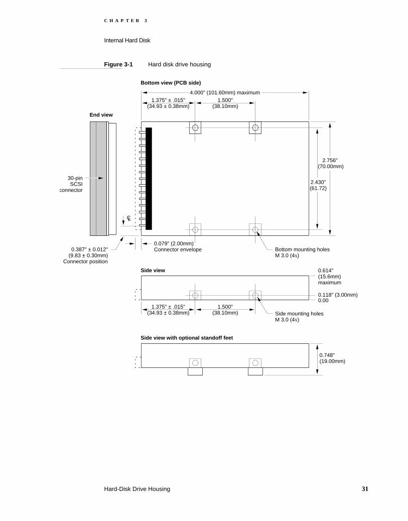
The hard disk drive is housed in the PowerBook Duo clamshell. Figure 3-1 shows detailed dimensions of the space allocated for the hard disk. It measures 4 inches by 2.75 inches and is 0.75 inches high. The height of the disk drive is critical, and must not exceed the specified 0.7539 inches. A bracket, shown in Figure 3-2 on page 32, attaches to the side of the hard disk, and holds it in place in the clamshell.
30 Hard-Disk Drive Housing
C H A P T E R 3
Internal Hard Disk
Figure 3-1 Hard disk drive housing
4.000" (101.60mm) maximum1.375" ± .015"
(34.93 ± 0.38mm)1.500"
(38.10mm)
2.430"(61.72)
2.756" (70.00mm)
Bottom mounting holesM 3.0 (4x)
0.079" (2.00mm)Connector envelope0.387" ± 0.012"
(9.83 ± 0.30mm)Connector position
30-pinSCSI
connector
CL
Bottom view (PCB side)
Side mounting holesM 3.0 (4x)
Side view
1.375" ± .015"(34.93 ± 0.38mm)
1.500"(38.10mm)
0.614"(15.6mm)maximum
0.118" (3.00mm)0.00
End view
Side view with optional standoff feet
0.748" (19.00mm)
Hard-Disk Drive Housing 31

C H A P T E R 3
Internal Hard Disk
Figure 3-2 Bracket for the hard disk drive
2.874" (73.00mm)
0.299" (7.60mm)
2x 0.079" (2.00mm)
0.125" (3.20mm)
(1.60mm)
0.188" (4.795±0.125mm)
0.549"
(13.95mm)1.5"
(38.10mm)
0.082" (2.10mm)
0.165" (4.20mm)
2x R full 4x R 0.039"
(1.00mm)2x R 0.059" (1.50mm)
CL
5
4
0 0.125" (3.200mm)10
(8.60)
(7.80)3x R 1.00
2.598" (66.00mm)
1.299" (33.00mm)
3x 0.137" (3.50mm)3x 0.275" (7.00mm)
0.137" (3.50mm)
3x 0.307" (7.80mm)
0.192" (4.900±0.125mm)
3x 0 0.118" (3.00mm)
6x R 0.059" (1.50mm)
4 Arrow indicates direction of material grain.
5 This surface to be free of burrs and sharp edges.
1. Interpret dimensions and tolerances per ANSI Y14.5M-1982
2. Material: CRS 1010-1020, 1.00 ± 0.05 (.0394 ± .0020) thick.
3. Finish: Zinc pre-plate per Mil.Spec. QQ-Z-325a Class 3 (0.00020) type II.
10 Mark part number, rev level, vendor I.D., and date code with 0.19±0.06 high permanent contrasting characters. Locate approximately where shown.
6. Maximum burr allowance is 15% of material thickness.
7. Starred (*) dimensions and notes are critical control, dimensions for Apple incoming quality control inspection.
8. Tooling required to make this part to be property of Apple Computer, Inc. and shall be permanently marked with Apple’s name and appropriate part number.
9. All dimensions apply after finish.
32 Hard-Disk Drive Housing

C H A P T E R 3
Internal Hard Disk
Operating Modes 3
The hard disk operates in five modes: power off, start-up, ready, seek/read/write, and standby. The PowerBook Duo hard disk does not implement a shutdown mode.
Power Off Mode 3In power off mode, no power is supplied to the disk, the heads are parked, and the spindle is not moving.
Start-up Mode 3The start-up period is the time after power or a SCSI command has been applied to the drive, and before the drive enters ready mode. On initial receipt of power, the disk goes into start-up mode, and the drive delays spindle motor start-up for 700 (+/- 50) milliseconds. The drive may perform self-diagnostic tests, or go through a calibration procedure, during this mode.
Ready Mode 3In this mode, the discs are spinning at the rated speed. The drive is able to accept and execute commands and may be accessed without delay. This is a command execution mode, during which the drive actuator is moving, or data is being written to or read from the disk.
Standby Mode 3During standby mode, no power is applied to the HDA actuator motor. The spindle motor spins at full speed, and the actuator is locked in position over the landing zone. The interface is enabled, and can send or receive commands. The drive may exit from this mode if it receives a SCSI command.
Power Requirements 3
The hard disk operates on +5 VDC, +/- 5 percent. Voltage ripple tolerance is 100 mV peak to peak, from DC to 10 MHz.
Operating Modes 33

C H A P T E R 3
Internal Hard Disk
Table 3-1 shows the maximum and mean current drain and power consumption requirements for the various operating modes of the 40MB and 80MB hard disk drives.
Hard Disk Interface 3
This section describes the interface requirements for the hard disk drive. It provides specifications and signal assignments for the SCSI connector.
Interface Requirements 3The interface to the hard disk is an ANSC X3T9.2 SCSI interface. Buffer size supports a 1:1 interleave. The drive supports the SCSI asynchronous information transfer. The data transfer rate is 1.5 megabytes per second (minimum). The embedded controller provides error recovery algorithms, which include error check and correction (ECC), seek retry, head offset (for open-loop systems), and defect management. Soft ID is optional. The drive responds to selection within 500 milliseconds of a SCSI hard reset. SCSI command overhead, defined as the time from the start of selection to the first disconnection of a read command (including message in/out phases) is 1.5 milliseconds maximum.
SCSI Connector 3The SCSI connector is a 30-pin, shrouded, male, keyed, right-angle SCSI connector. It is located, as shown in Figure 3-1, within the envelope of the mounting case. Pin 1 is the rightmost pin of the upper row when viewing the connector with the drive top cover up.
* Random operation values are RMS values, with a 40% random seek, 40% write/read (1 write in 10 reads), and 20% idle mode.
Table 3-1 Hard disk current drain and power consumption
Mode Current (amps) Power (watts)
Mean Max. Mean Max.
Start-up --- 1.000 --- 5.00
Random Operation* 0.500 0.700 2.50 3.50
Idle 0.300 0.400 1.50 2.00
Standby 0.200 0.250 1.00 1.25
Shutdown 0.050 0.075 0.25 0.38
NOTE During a read operation, +5 V power may be intermittently interrupted without permanent damage or loss of data. During a write operation, +5 V power may be interrupted without causing permanent damage, or data loss of more than one sector.
34 Hard Disk Interface

C H A P T E R 3
Internal Hard Disk
The key slot is also up. This connector also supplies +5 V power to the hard disk. Table 3-2 shows the signal assignments.
Terminator 3The hard disk has 1000-ohm termination resistors for all signal lines. They pull up to termination power.
Table 3-2 Hard disk SCSI connector signal assignments
Pin Signal name Description
1, 2, 15, 29, 30 +5V HDISK +5 V power
3, 4, 5, 11, 25, 27, 28 GROUND Ground
6 /REQ Access request
7 /C/D When active (low) indicates that data is on the SCSI bus. When high, indicates that control signals are on the bus.
8 /I/O Controls the direction of data movement. When this signal is low, data is output, when it is high, data is input.
9 /RST SCSI bus reset
10 /SEL Select
12 /MSG Message phase
13 /ATN Attention indicator
14 /ACK Acknowledge (handshake signal)
16 /BSY Busy
17 /DB[7] Data bus bit 7
18 /DBP Data bus parity
19 /DB[5] Data bus bit 5
20 /DB[6] Data bus bit 6
21 /DB[3] Data bus bit 3
22 /DB[4] Data bus bit 4
23 /DB[1] Data bus bit 1
24 /DB[2] Data bus bit 2
26 /DB[0] Data bus bit 0
Hard Disk Interface 35


C H A P T E R 4
Figure 4-0Listing 4-0Table 4-0
Input/Output Interfaces 4

C H A P T E R 4
Input/Output Interfaces
The PowerBook Duo input/output interface consists of the following elements:
The main expansion connector, which allows you to connect expansion devices, such as the Macintosh Duo MiniDock, PowerBook Duo Floppy Adapter, and Macintosh Duo Dock, to the PowerBook Duo.
An 8-pin DIN serial communications connector, which allows you to connect an external modem, printer, or network (LocalTalk).
A power adapter input, which enables you to connect to AC wall power
A phone jack to allow you to connect the internal modem to the phone line
An on/off button
These connectors are located on the rear panel of the PowerBook Duo, as shown in Figure 4-1.
The PowerBook Duo logic board has additional connectors that enable the computer to interface with the internal hard disk, the DRAM expansion card, and the internal modem. The interfaces are described in other chapters of Part I of this developer note.
The internal hard disk interface is described in Chapter 3, “Internal Hard Disk.”
The modem interface is described in Chapter 5, “Internal Modem.”
The DRAM expansion card connector is described in Chapter 6, “DRAM Expansion Cards.”
Figure 4-1 Rear panel of the PowerBook Duo
Input formodem
152-pin mainexpansionconnector
Rear view of PowerBook Duo connector panel
Powerconnector
Serial port connector
detail
1
34
8
5
7 6
2
These pins areconnected tochassis ground
On/offbutton
38

C H A P T E R 4
Input/Output Interfaces
Main Expansion Connector 4
The 152-pin main expansion connector provides the interface between the PowerBook Duo, and expansion features such as the PowerBook Duo Floppy Adapter and the Macintosh Duo MiniDock. These devices contain matching 152-pin connectors that plug directly into the connector on the PowerBook Duo main logic board. The expansion connector gives the devices direct access to the microprocessor’s 32-bit address bus, 32-bit data bus, and control signals. It also provides access to power, control, and status signals in other parts of the computer. There are two versions of the connector, as shown below.
JAE part number JX20-152BA-D1LT-H is the right-angle version of the connector. It is used for the PowerBook Duo Floppy Adapter.
JAE part number JX20-152BA-D1ST-H is the straight version of the connector. It is used for the Macintosh Duo MiniDock.
The 152-pin connector on the PowerBook Duo computer accepts a maximum insertion load of 28 pounds, when an expansion device is plugged into it. The connector is designed to withstand approximately 5000 lifetime insertions, and, based on current testing, has a tolerance for misalignment of 9 thousandths of an inch in both vertical and horizontal directions. Two holes, one on each side of the connector, serve as receptacles for the guide pins on the expansion device.
Table 4-1 shows the signal assignments for the main expansion connector. A slash before a signal name (/RST) indicates an active-low signal.
Table 4-1 Main expansion connector signal assignments
Pin number Signal name Description
1, 2, 77, 78, 79 PR +24V EXT Raw +24 V from AC adapter
3 /PLUG IN Power surge control (grounded in the expansion device)
4, 19, 20, 30, 38, 39, 51, 61, 65, 66, 80, 81, 115, 141, 142
GND Logic ground
5, 6, 82 PR MAIN BAT POS Positive battery power output
7 /ON/OFF OUT On/off button
8 /CIOUT Cache inhibit out
9 /STERM Synchronous termination
10 /DS Data strobe
11 /AS Address strobe
Main Expansion Connector 39

C H A P T E R 4
Input/Output Interfaces
12, 29, 42, 55, 60, 64
+5V MAIN OUT +5 V regulated power
13 /HALT Halt
14 /BERR Bus error
15 /BGACK Bus grant acknowledge
16 /IPL0 Interrupt priority level signal 0 (least significant bit)
17 /IPL1 Interrupt priority level signal 1
18 /IPL2 Interrupt priority level signal 2 (most significant bit)
21 ADDR[0] Address bit 0
22 ADDR[2] Address bit 2
23 ADDR[4] Address bit 4
24 ADDR[6] Address bit 6
25 ADDR[8] Address bit 8
26 ADDR[10] Address bit 10
27 ADDR[12] Address bit 12
28 ADDR[14] Address bit 14
31 ADDR[18] Address bit 18
32 ADDR[20] Address bit 20
33 ADDR[22] Address bit 22
34 ADDR[24] Address bit 24
35 ADDR[26] Address bit 26
36 ADDR[28] Address bit 28
37 ADDR[30] Address bit 30
40 IOCLK 15.6672 MHz I/O clock
41 SIZ[1] Transfer size bit 1
43 DATA[0] Data bit 0
44 DATA[1] Data bit 1
45 DATA[2] Data bit 2
46 DATA[3] Data bit 3
47 DATA[4] Data bit 4
48 DATA[5] Data bit 5
Table 4-1 Main expansion connector signal assignments (continued)
Pin number Signal name Description
40 Main Expansion Connector

C H A P T E R 4
Input/Output Interfaces
49 DATA[6] Data bit 6
50 DATA[7] Data bit 7
52 DATA[17] Data bit 17
53 DATA[18] Data bit 18
54 DATA[19] Data bit 19
56 DATA[20] Data bit 20
57 DATA[21] Data bit 21
58 DATA[22] Data bit 22
59 DATA[23] Data bit 23
62 /SCC IRQ SCC interrupt request
63 SERVEE –5 V for SCC transceivers
67 +8V SOUND Special “clean” +8 V power for sound output
68 +5V MODEM +5 V power for modem
69 LINET/R Modem DAA line talk/receive
70 +5V SOUND +5 V power for sound output
71 SND OUT R Sound output right channel
72 SND OUT L Sound output left channel
73 EXT MIC FILT R Right input signal from external microphone
74 EXT MIC FILT L Left input signal from external microphone
75, 76, 151, 152 DAA GND Modem ground
83 ADB DATA Apple Desktop Bus data
84 /ADBPWRON ADB power-on key
85 /CBACK Cache burst acknowledge
86 /CBREQ Cache burst request
87 /DSACK1 Data size acknowledge bit 1
88 /DSACK0 Data size acknowledge bit 0
89 /BR Bus request
90 /BG Bus grant
91 /SLEEP Sleep-state signal
92 FC[1] Function code bit 1
Table 4-1 Main expansion connector signal assignments (continued)
Pin number Signal name Description
Main Expansion Connector 41
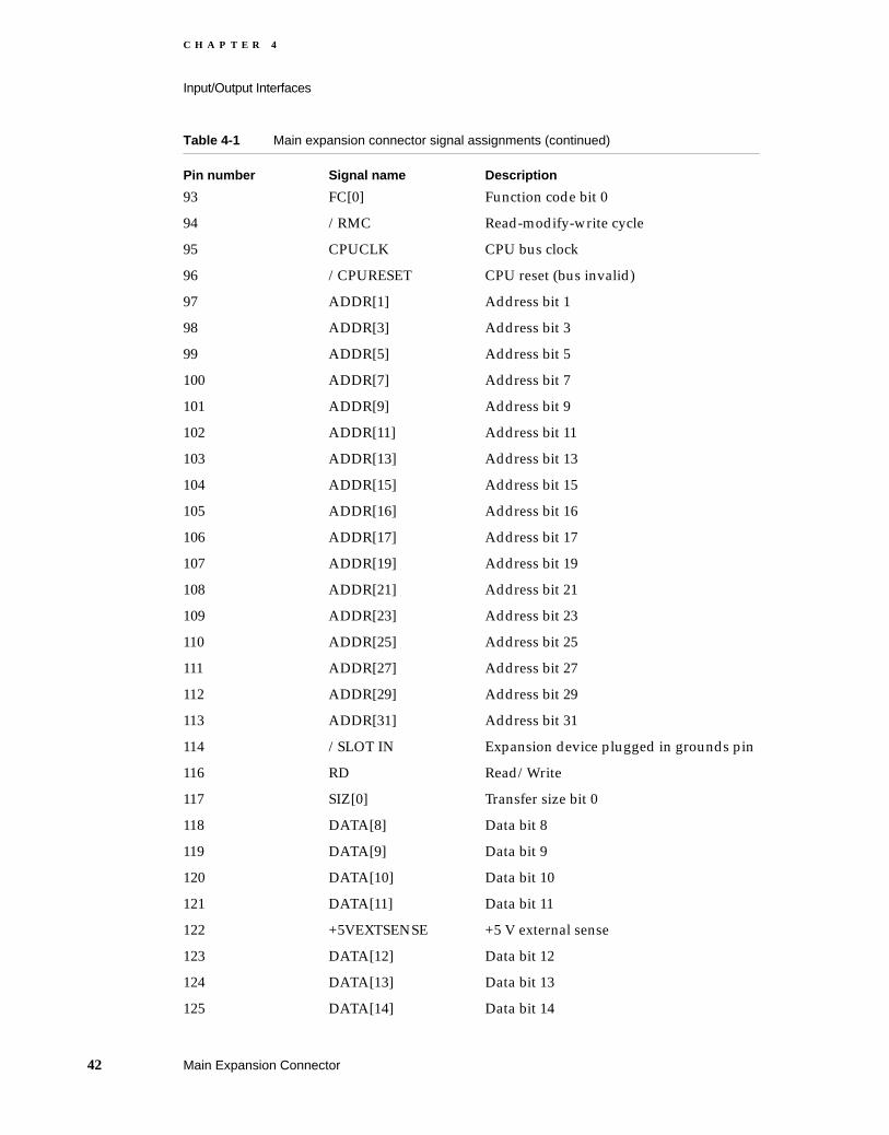
C H A P T E R 4
Input/Output Interfaces
93 FC[0] Function code bit 0
94 /RMC Read-modify-write cycle
95 CPUCLK CPU bus clock
96 /CPURESET CPU reset (bus invalid)
97 ADDR[1] Address bit 1
98 ADDR[3] Address bit 3
99 ADDR[5] Address bit 5
100 ADDR[7] Address bit 7
101 ADDR[9] Address bit 9
102 ADDR[11] Address bit 11
103 ADDR[13] Address bit 13
104 ADDR[15] Address bit 15
105 ADDR[16] Address bit 16
106 ADDR[17] Address bit 17
107 ADDR[19] Address bit 19
108 ADDR[21] Address bit 21
109 ADDR[23] Address bit 23
110 ADDR[25] Address bit 25
111 ADDR[27] Address bit 27
112 ADDR[29] Address bit 29
113 ADDR[31] Address bit 31
114 /SLOT IN Expansion device plugged in grounds pin
116 RD Read/Write
117 SIZ[0] Transfer size bit 0
118 DATA[8] Data bit 8
119 DATA[9] Data bit 9
120 DATA[10] Data bit 10
121 DATA[11] Data bit 11
122 +5VEXTSENSE +5 V external sense
123 DATA[12] Data bit 12
124 DATA[13] Data bit 13
125 DATA[14] Data bit 14
Table 4-1 Main expansion connector signal assignments (continued)
Pin number Signal name Description
42 Main Expansion Connector

C H A P T E R 4
Input/Output Interfaces
Serial Port Connector 4
The serial interface controlled by the SCC portion of the Combo chip, is connected to the external world through an eight-pin, miniature DIN connector. Each signal passes through a series 47-ohm termination resistor. Table 4-2 on the next page lists serial port connector signal assignments. The table indicates to which pins on the SCC Combo chip the serial port signals are connected.
126 DATA[15] Data bit 15
127 DATA[16] Data bit 16
128 DATA[24] Data bit 24
129 DATA[25] Data bit 25
130 DATA[26] Data bit 26
131 DATA[27] Data bit 27
132 DATA[28] Data bit 28
133 DATA[29] Data bit 29
134 DATA[30] Data bit 30
135 DATA[31] Data bit 31
136 MI Memory controller inhibit for cache access
137 /SWIM CS SWIM chip select
138 /SLOT E IRQ Pseudo-NuBus expansion slot E interrupt
139 /PFW Power fail warning (shutdown bit)
140 /IO RESET Reset output to I/O systems
143 DAA CNTLF Modem DAA control
144 DAA ID IN ID input from 152-pin connector to modem card
145 /RING DET Ring detect signal from the modem DAA
146 /RB DVR Modem relay B driver
147 /RA DVR Modem relay A driver
148 EXT MIC SEL External microphone plugged in
149 NC(EXT MIC) No connect (external line or mike level)
150 /SPKR SEL External speaker plugged in
Table 4-1 Main expansion connector signal assignments (continued)
Pin number Signal name Description
Serial Port Connector 43

C H A P T E R 4
Input/Output Interfaces
Power Connector 4
The power connector on the rear panel enables you to connect an external power source for charging batteries. Table 4-3 summarizes the signal assignments for the connector.
Table 4-2 Serial port connector signal assignments
Pin Signal name Description
1 HSKo Handshake output. Connected to the Request to Send (RTS) pin on the Combo chip. Tristated when the Data Terminal Ready (DTR) signal is inactive.
2 HSKi Handshake input. Connected to the Transmit Receive Clock (TRXC) pin on the Combo chip.
3 /TXD Transmit data (inverted). Connected to the Transmit Data (TXD) pin on the Combo chip. Tristated when DTR is inactive
4 SG Signal ground. Connected to logic and chassis ground.
5 /RXD Receive data (inverted). Connected to the Receive Data (RXD) pin on the Combo chip.
6 TXD Transmit data. Connected to the Transmit Data (TXD) pin on the Combo chip. Tristated when DTR is inactive
7 GPi General purpose input. Connected to the Data Carrier Detect (DCD) pin on the Combo chip.
8 RXD Receive data. Connected to the Receive Data (RXD) pin on the Combo chip.
9, 10, 11 GND These pins are connected to chassis ground
Table 4-3 Power connector signal assignments
Pin Signal name Description
1 +24V EXT Raw 24 V power
2 P/S GND Point where chassis ground connects to p/s ground
3 ADB DATA ADB data
4, 5 Ground Safety ground
44 Power Connector
C H A P T E R 4
Input/Output Interfaces
RJ-11 Modem Connector 4
A standard RJ-11 phone jack provides the modem interface with the telephone line. Modem functions are described in detail in Chapter 5, “Internal Modem.”
RJ-11 Modem Connector 45


C H A P T E R 5
Figure 5-0Listing 5-0Table 5-0
Internal Modem 5

C H A P T E R 5
Internal Modem
Since the PowerBook Duo is portable, the communications features of the machine are crucial. The computer has a PSTN (public switch telephone network) modem, known as the 3615 modem, that provides wide-area connectivity through its modem and fax capabilities.
The data modem is full-duplex and asynchronous, and supports all popular standards up to and including CCITT V.32 bis (14400bps). The modem also performs fax emulation, which allows you to send and receive Group 3 fax documents, using CCITT V.29 (7200-9600 bps).
Hardware design and protocol standards qualify the modem for PTT approval in the United States, Canada, and Japan (domestic modem). A modified version, known as the international modem, conforms to PTT standards for European and other overseas countries. Figure 5-1 shows an outline of the domestic version of the modem card, and Figure 5-2 shows an outline of the international version.
The modem card plugs into a 50-pin connector on the side of the PowerBook Duo’s main logic board. The connector can accommodate the Apple modem card or a compatible third-party modem card.
Modem Hardware 5
This section describes the hardware required to implement the modem function, including the modem cards and telephone line interfaces.
Mechanical Specifications 5The components required to implement the PowerBook Duo modem are mounted on a printed circuit card, referred to as the modem card. Figure 5-1 and Figure 5-2 provide the mechanical specifications needed to design PowerBook Duo modem cards for domestic and international applications. The figures include card dimensions, and connector types and locations.
48 Modem Hardware

C H A P T E R 5
Internal Modem
Figure 5-1 Outline of domestic and international modem cards
Modem Implementation for Different Markets 5To prepare the PowerBook Duo for international markets, the built-in modem must meet each overseas country’s phone system interface and modem performance requirements. This means that modem software, and occasionally hardware, vary from country to country. There are two versions of the modem card: one which targets U.S, Canadian, and Japanese markets, and a second version for use in all other overseas countries. Each version of the modem consists of the same basic elements: the data pump and the telephone interface, or DAA (data access arrangement). It is the DAA that changes to accommodate the requirements of different phone systems.
As shown in Figure 5-3, all domestic modem functions are housed on the same card. The international version of the card has an external DAA extension, which can be replaced without modification to the modem’s main logic card, or to the PowerBook Duo main logic board.
Switch,on/off
Switch,wake up
External DAAconnector
(Mini-DIN-8)
50-pin connector
International modem
Switch,on/off
Switch,wake up
Phone jackconnector
RJ-11
50-pin connector
Domestic modem
Modem Hardware 49

C H A P T E R 5
Internal Modem
Figure 5-2 Modem card dimensions
0.165"(4.19mm)
0
0
0 0.133+.003 -.000
1.457" (37.00mm)1.378" (35.00mm)
-1.629"(-41.39mm)
-1.994(-50.64mm)
pin 1
-2.368"(-60.14mm)
1.750" (44.45mm)
1.363" (34.63mm)
Pin 1 1.565" (39.75mm)1.545" (39.25mm)CL
-0.410" (-10.41mm)
0.244" (6.19mm)-2.102"(-53.39mm)
-1.962" (0.92mm)pin 1
-0.135" (-3.42mm) pin 1
-0.131"(3.33mm) CL
1.750" (44.45mm)
1.595" (40.51 mm)
3.38 mm+0.08 -0.00
International
0.165"(4.19mm)
0
0
0 0.133+.003 -.000
1.457" (37.00mm)1.378" (35.00mm)
-1.629"(-41.39mm)
-1.994(-50.64mm)
pin 1
-2.368"(-60.14mm)
1.750" (44.45mm)
1.363" (34.63mm)
Pin 1 1.565" (39.75mm)1.545" (39.25mm)CL
-0.410" (-10.41mm)
0.244" (6.19mm)-2.102"(-53.39mm)
-1.962" (0.92mm)pin 1
-0.135" (-3.42mm) pin 1
-0.056" Pin 1(-1.43mm)
1.750" (44.45mm)
1.595" (40.51 mm)
3.38 mm+0.08 -0.00
Domestic
1.366" (34.70mm) Pin 1
50 Modem Hardware

C H A P T E R 5
Internal Modem
Figure 5-3 Modem card component height
2.162"(54.93mm)
Pin 10.188"(4.76mm)
1.266"(32.15mm)
1.179"(29.95mm)
0.205"(5.20mm)
1.995"(50.68mm)
0
Componentheight0.244" (6.20mm)maximum
0.067"(1.70mm)
2.133"(54.18mm)
1.950"(49.53mm)
2.200"(55.88mm)
1.266"(32.15mm)
1.179"(29.95mm)
Referencepoints
0
0
0.020"(0.50mm)
Unless otherwise specified,component height and/or leadlength 0.146" (3.70mm)
No components in shaded areas
70-pinconnector
(P-10)
Modem Hardware 51

C H A P T E R 5
Internal Modem
Figure 5-4 Simplified view of modem card functions
Telephone Line Interface 5The DAA (data access arrangement) provides the telephone line interface. In the domestic version of the modem card, the DAA is an integral portion of the card, and communicates with the telephone line through the RJ-11 connector. (See Figure 5-3.) The international version of the card has a mini DIN-8 connector into which the external DAA is plugged. The external DAA contains the RJ-11 connector required to connect to the telephone line.
PowerBook Duologic board
Modem card RJ-11
144DPLdatapump
Domestic
PowerBook Duologic board
Modem card MD-8
144DPLdatapump
International
DAA(country specific)RJ-11
Connector DAA
Connector Interface
52 Modem Hardware

C H A P T E R 5
Internal Modem
To operate properly in a given country, the modem must know what requirements it is supposed to meet. The country identification is embedded in each DAA (internal or external) and is accessed by the modem software.
Software Architecture 5
Many of the modem and fax functions are implemented in software running on the PowerBook Duo’s operating system. This allows easy field upgrades, and reduces hardware costs. This type of architecture also makes it easier to add new features to the modem.
The 3615 modem software architecture consists of the following groups of components:
A modem control panel
A modem CTB connection tool, the CTB serial driver replacement
Fax terminal software
A fax terminal extension, fax terminal background application, fax sender printer driver PDEF, fax custom cover page applications, fax viewing application
Modem Control Panel 5The modem control panel provides an interface with the modem stack. If the modem stack is the fax modem itself, the control panel is the front end of this system.
Communications ToolBox 5The 3615 modem has a communications ToolBox (CTB) connection tool that provides a standard interface to the modem and allows it to be used by any CTB-based applica-tions. The system also supports non-CTB aware applications through a serial driver replacement. (See also “Communicating with the Modem” later in this chapter.)
Fax Terminal Software 5The fax terminal software provides fax send and receive capabilities for the 3615 modem. It provides the user interface and supports communication with the modem. The software consists of the following elements:
FAX Sender (PDEF), which comprises the FAX phone book, Options, Cover information, and FAX Preview.
FAX Extension Driver, a software driver.
FAX Monitor Application, which monitors the sending and receiving of faxes.
Software Architecture 53

C H A P T E R 5
Internal Modem
FAX Sender 5
FAX Sender is a printer driver file, similar to ImageWriter or LaserWriter. Accessed through dialog boxes, it allows you to send a fax by “printing.” Any application that can print via the standard Macintosh Print Manager can send faxes using the 3615 modem. The FAX Sender contains a fax phone book feature that you can reference and edit. Options allow you to select between tone and pulse dialling, to select and preset the send time, and to enter a calling card number. Cover Info allows the sender to produce a custom fax cover page. The Preview button displays the fax, and allows the sender to see how it looks before sending it. The Send and Cancel buttons are part of the Preview dialog.
FAX Extension Driver 5
FAX Extension Driver is a software driver. It supports software, that is contained in an INIT, and placed in the System Extension Folder. The driver functions as a fax Send/Receive Terminal, performing QuickDraw/T4 image conversions, and calling upon the T.30 services of the fax module in the Modem Stack to transmit or receive a fax.
FAX Terminal 5
FAX Terminal is a background application that resides in the Control Panel Folder. Much like Print Monitor in appearance, it communicates with the FAX Extension Driver, handles queuing of faxes being sent or received, and provides status information. Like Print Monitor, FAX Terminal can be opened from the Finder, but it is normally opened automatically by the FAX Extension Driver.
See also the section “Fax Send and Receive Capabilities,” later in this chapter.
Compatibility 5The 3615 modem has dependencies on System 7, the Macintosh Communications Toolbox, and the MCP (Macintosh coprocessor platform) A/ROSE driver.
The 3615 modem can be used with terminal emulation, front-end connection services, such as AppleLink or MacWorkStation applications. It is also compatible with server products, such as 976, AppleTalk, and Internet Router.
Modem Features 5
This section describes features of the modem, including ways of accessing, arbitrating between multiple clients, handling ring messages, correcting transmission errors, and compression data.
54 Modem Features
C H A P T E R 5
Internal Modem
Communicating with the Modem 5The 3615 modem provides two methods of accessing the program: a CTB connection tool for CTB-aware applications; and a serial driver for non-CTB-aware applications.
The CTB-aware application selects the 3615 modem by selecting the modem’s connection tool. The client application makes appropriate CTB read and write calls to pass the AT commands and responses, as well as client data, to the 3615 modem, through the connection tool. In front-end and server-type applications, such as AppleLink, a CCL (communication control language ) script selects the modem connection tool automatically, making all commands to the modem without user intervention. Some applications require you to select and configure the modem, in which case, the 3615’s CTB appears as a choice in the standard CTB-connect dialog menu.
For non-CTB-aware applications, a serial driver replacement maps serial-drive prime, and routes calls onto the connection tool equivalents. In this way, 976 and other non-CTB applications function as if they are speaking to an external modem over serial port A.
Arbitration 5The 3615 modem allows several software clients to set themselves up to use the modem, and client arbitration is required to ensure an orderly process. Client arbitration is implemented through the concept of “associations.” The 3615 connection tool creates a logical connection, or association, between application program and modem. Associations may be Data or fax, and may be set up in user or server mode, with user mode having the higher priority. The client application selects the association through the Communications Tool Box scripting mechanism.
User mode is more commonly used by terminal emulators, such as MacTerminal, and front-end applications like AppleLink. The application takes control of the modem and places an outgoing call. Server applications, such as 976 and FAX Terminal, use server mode, and wait passively for incoming calls, although they can also actively place calls. Server mode is commonly used for sending and receiving faxes.
Data and fax associations use different modem transmission protocols, and the modem can decide how incoming calls should be routed.
The 3615 modem supports one association in user mode (data-user), and two associa-tions in server mode (data-server and fax-server). If a client requests an association type already claimed by another client, the request is denied, and an error message is issued. The modem maintains a set of s-registers and state variables, so that each modem client can treat the modem as exclusive. However, the modem can be in use (phone off the hook) with only one client at a time, and any attempt to manipulate the phone line when it is in use is denied, with the explanation that the line is “in use.”
Modem Features 55

C H A P T E R 5
Internal Modem
Ring Messages 5Since associations allow the modem to support multiple clients (fax, AppleTalk, Remote Access, and AppleLink) all at once, it is necessary to define the way in which ring messages and the S0 register are handled, for data-user associations, and non-date-user associations.
Data-User Associations 5
The data-user association takes precedence over other association types. When a data-user association exists, its s register, S0, decides how many rings will initiate an auto-matic answer, regardless of the S0 register settings of the server associations. There are two possible situations.
S0 = 0. The 3615 modem answers only if an ATA command arrives from the data-user association.
S0 > 0. The 3615 modem answers after the number of rings specified in the S0 register. If the incoming call is a fax call, and there is a fax-server association open, the call will go to that association. Otherwise, it will go to the data-user association.
Non-Data User Associations 5
When no data-user association is open, and at least one server association is open, if the server has set the S0 register to 0, we apply the convention that the server does not want to receive calls, but may still want to place calls. This implies that servers can never answer by counting the ring messages, or looking at register S1, and then issuing the ATA command. There are two possible scenarios: the first where both a fax server and data server exist, and the second where there is only one active server.
If both a fax server and a data server are active, one of the following conditions will prevail, based upon the setting of the S0 register.
Both servers have set their S0 registers to 0. The 3615 modem will not answer automatically.
Both servers have set their S0 registers to more than 0. The 3615 modem answers automatically after the minimum number of rings specified in one of the registers. So, if the fax server S0 register is set to 2, and the data server S0 register to 3, the modem will answer after two rings, and pass the call to the appropriate server. That is, it will pass fax calls to the fax server, and data calls to the data server.
One server has set its S0 register to 0, and the other to a >0. The 3615 modem will answer the higher number of rings automatically, and pass the call only to the server association for which S0 is >0, provided of course that it is the appropriate kind of call: fax calls to the fax server, and data calls to the data server.
If only one server is active, the setting of the S0 register determines how the modem will implement the automatic answering procedure.
In all cases, the modem will have received the rings and answered the phone before it has determined to whom the call should be directed (data user, data server, fax server). The modem therefore has a scheme for sending the standard ring result code messages to the appropriate client, in a way that will meet the your expectations.
56 Modem Features

C H A P T E R 5
Internal Modem
If a data-user association exists, it is most likely to be a terminal emulator, or a front-end applications such as MacTerminal, MacWorkStation, or AppleLink. The ring messages may be observed by the human user, or detected by a CCL script. For this reason, the ring messages will be sent each time a ring is detected until the phone has been answered. This satisfies your expectation of seeing the ring message as the ring occurs.
Server-oriented data and fax tasks are automated by CCL scripts, which can easily specify that the modem should answer automatically by setting the S0 register to a >0 value.
NoteServer modes do not receive ring messages.
Error Correction and Data Compression 5The modem is equipped with two industry-standard, transparent, error-correction and data-compression protocols: Microcom Networking Protocol (MNP II-V) and the CCITT standard V.42/V.42bis. Compression for MNP 5 is up to 2:1. For V.42bis it is up to 4:1.
These protocols improve transmission speed by up to 4 times the actual bit rate when connected to compatible modems. The protocols also provide a more efficient and reliable link. They are particularly useful in remote access types of applications, which need to pass non-text data quickly and reliably.
The modem normally attempts to achieve the best link possible when negotiating with a second remote modem, using MNP 2 through 5 and V.42/V.42bis error correction and data compression protocols. The modems systematically fall back on negotiation failures until they settle on a protocol, or hang up. It is possible to override and control which protocols are used by issuing AT commands.
Installation 5
The 3615 modem consists of two system files: a Control Panel, which is placed in the Control Panels Folder, and a 3615-specific CTB Connection Tool (3615 Modem Tool), which is placed in the System Extensions folder. A System 7 Installer Script is provided to install the software on the PowerBook Duo.
Fax Send and Receive Capabilities 5
Fax terminal software allows faxes to be sent and received. Faxes are sent by “Printing.” This involves selecting the “FAX Sender” PDEF in the Chooser. A fax cover page application allows the sender to create and edit custom cover pages.
Faxes received may be viewed, copied, printed, or saved as MacDraw-compatible documents, using a fax viewer application.
Installation 57
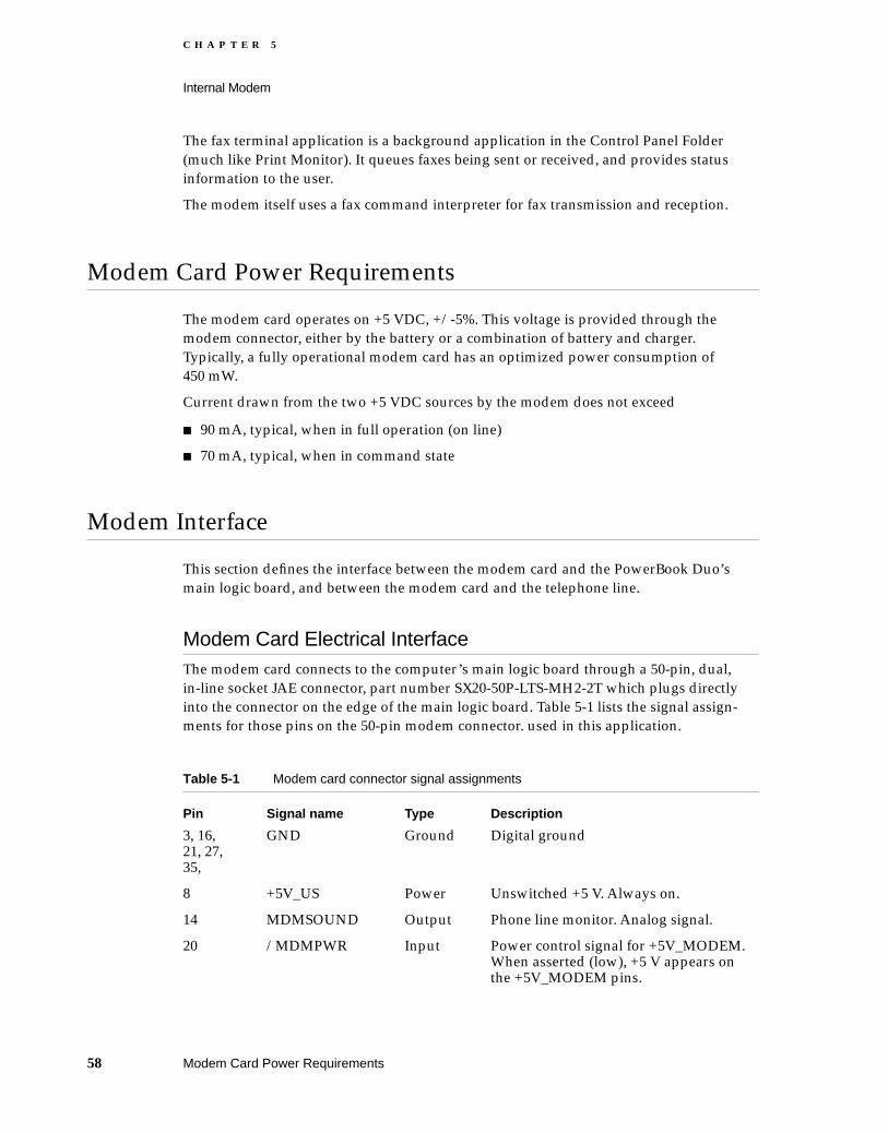
C H A P T E R 5
Internal Modem
The fax terminal application is a background application in the Control Panel Folder (much like Print Monitor). It queues faxes being sent or received, and provides status information to the user.
The modem itself uses a fax command interpreter for fax transmission and reception.
Modem Card Power Requirements 5
The modem card operates on +5 VDC, +/-5%. This voltage is provided through the modem connector, either by the battery or a combination of battery and charger. Typically, a fully operational modem card has an optimized power consumption of 450 mW.
Current drawn from the two +5 VDC sources by the modem does not exceed
90 mA, typical, when in full operation (on line)
70 mA, typical, when in command state
Modem Interface 5
This section defines the interface between the modem card and the PowerBook Duo’s main logic board, and between the modem card and the telephone line.
Modem Card Electrical Interface 5The modem card connects to the computer’s main logic board through a 50-pin, dual, in-line socket JAE connector, part number SX20-50P-LTS-MH2-2T which plugs directly into the connector on the edge of the main logic board. Table 5-1 lists the signal assign-ments for those pins on the 50-pin modem connector. used in this application.
Table 5-1 Modem card connector signal assignments
Pin Signal name Type Description
3, 16, 21, 27, 35,
GND Ground Digital ground
8 +5V_US Power Unswitched +5 V. Always on.
14 MDMSOUND Output Phone line monitor. Analog signal.
20 /MDMPWR Input Power control signal for +5V_MODEM. When asserted (low), +5 V appears on the +5V_MODEM pins.
58 Modem Card Power Requirements

C H A P T E R 5
Internal Modem
Modem Card Hardware Interface 5Figures 5-4 through 5-6 show the hardware interfaces between modem card and other hardware elements in the PowerBook Duo System.
Stand-alone PowerBook Duo 5
Figure 5-5 o0n the next page shows the configuration for the stand-alone PowerBook Duo computer. The modem card (domestic version) plugs in to the 50-pin connector on the side of the PowerBook Duo’s main logic board.
21 RAW_+10V Power Unregulated +10 V. It is on when the CPU is awake (maximum current 25mA).
40, 41 +5V_MODEM Power +5 V modem power. On when /MDMPWR is asserted.
42 SERVEE (-5V) Power -5 V power. On when CPU is awake.
44, 45 DAA GND Ground Analog ground
47 KEYSCANX[5] Output Keyscan line to the Power Manager, for power-on button.
49 KEYSCANX[0] Output Keyscan line to the Power Manager, for power-on button.
50 ON/OFF_OUT Output CPU on/off control signal to Power Manager.
The signals on the following pins are routed from the modem’s 50-pin connector, through the 152-pin expansion connector, to support phone line interfaces in expansion devices.
6 /RBDVR Open collector
Relay B Driver from modem card to modem adapter card (DAA) in expansion device - MiniDock or Duo Dock.
33 /RADVR Open collector
Relay A driver from the data pump.
36 /RINGDET Input (wire-or)
Ring detect signal from an expansion device’s adapter card (DAA).
46 LINE_T/R Input/output
Voice-band analog signal to or from an expansion device’s modem adapter card (DAA).
Table 5-1 Modem card connector signal assignments (continued)
Pin Signal name Type Description
Modem Interface 59

C H A P T E R 5
Internal Modem
Figure 5-5 Interface between modem card and the PowerBook Duo
PowerBook Duo with MiniDock 5
Figure 5-6 shows the interface when the PowerBook Duo is attached to a MiniDock.The modem card plugs into the 50-pin connector on the PowerBook Duo’s main logic board. This board interfaces with the MiniDock’s main logic board via the 152-pin main expansion connector. The modem adapter card (internal DAA) provides the link to the telephone line, and it plugs in to the 10-pin connector on the side of the MiniDock’s main logic board.
PowerBook Duo with Duo Dock 5
Figure 5-7 on page 62 shows the interface when the PowerBook Duo is attached to a Duo Dock.The modem card plugs into the 50-pin connector on the PowerBook Duo’s main logic board. This board interfaces with the Duo Dock’s main logic board via the 152-pin main expansion connector. The modem adapter card (internal DAA) provides the link to the telephone line, and it plugs in to the 10-pin connector on the side of the Duo Dock’s main logic board.
Modem hardware Main CPU/logic
Hookrelay
Ring signaldetector
152-pin connector
Powersupply
RJ-11
Domestic modem card PowerBook Duo main logic board
50-p
in c
onne
ctor
ACadapter
To centraloffice
Loop current
60 Modem Interface
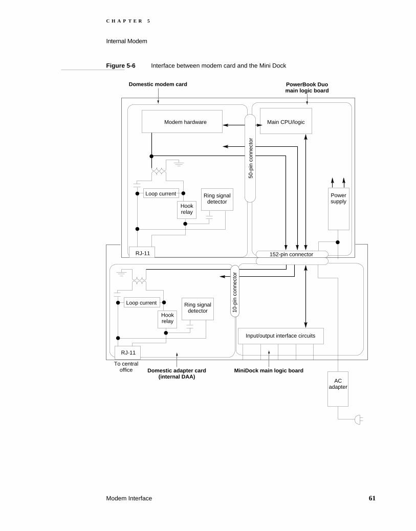
C H A P T E R 5
Internal Modem
Figure 5-6 Interface between modem card and the Mini Dock
ACadapter
Modem hardware Main CPU/logic
Loop current
Hookrelay
Ring signaldetector
152-pin connector
Powersupply
RJ-11
Domestic modem card PowerBook Duo main logic board
50-p
in c
onne
ctor
10-p
in c
onne
ctor
Hookrelay
Ring signaldetector
RJ-11
Input/output interface circuits
Domestic adapter card (internal DAA)
To centraloffice MiniDock main logic board
Loop current
Modem Interface 61
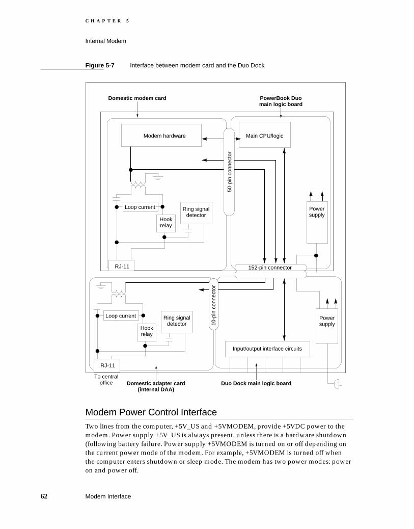
C H A P T E R 5
Internal Modem
Figure 5-7 Interface between modem card and the Duo Dock
Modem Power Control Interface 5Two lines from the computer, +5V_US and +5VMODEM, provide +5VDC power to the modem. Power supply +5V_US is always present, unless there is a hardware shutdown (following battery failure. Power supply +5VMODEM is turned on or off depending on the current power mode of the modem. For example, +5VMODEM is turned off when the computer enters shutdown or sleep mode. The modem has two power modes: power on and power off.
Modem hardware Main CPU/logic
Loop current
Hookrelay
Ring signaldetector
152-pin connector
Powersupply
RJ-11
Domestic modem card
50-p
in c
onne
ctor
10-p
in c
onne
ctor
Hookrelay
Ring signaldetector
RJ-11
Input/output interface circuits
Domestic adapter card (internal DAA)
To centraloffice Duo Dock main logic board
PowerBook Duo main logic board
Powersupply
Loop current
62 Modem Interface

C H A P T E R 5
Internal Modem
Telephone Line Electrical Interface 5Modem card design includes a balanced, two-wire telephone interface that meets U.S. (FCC part 68), DOC, and JATE telephone line interface specifications. The physical part of the interface consists of an RJ-11 phone jack, (J3) with six slots and four contacts. The middle two contacts are used for TIP and RING signals. All others are unused.
Modem/fax Specifications 5
Table 5-2 lists modem/fax specifications. The specifications are for reference only.
Table 5-2 Modem/fax specifications
Full duplex data standards
Standard Speed (bits per second)
V.32 bis/V.32 14000 bps, 12000 bps, 9600 bps, 7200 bps, 4800 bps
V.22 bis 2400 bps
V22 and Bell 212A 1200 bps
V.23 1200/75 bps asymmetrical
V.21 and Bell 103 300 bps
Transmit carrier frequencies
V.22 bis/V.22/212A Transmit carrier
Originate 1200 Hz
Answer 2400 Hz
Bell 103 Mark Space
Originate 1720 1070
Answer 2225 2025
V.21 Mark Space
Originate 980 1180
Answer 1650 1850
V.29
Carrier 1700 Hz
V.27ter
Guard tone frequencies and transmit levels (CCITT only)
Frequency Transmit level
1800 Hz, +/- 20 Hz, @6, +/- 1 dB below transmit carrier level
550 Hz, +/- 20 Hz, @ 3, +/- 1 dB below transmit carrier level
Modem/fax Specifications 63

C H A P T E R 5
Internal Modem
Answer tone frequency
Standard Frequency
V.22 bis/V.22/V.21 2100 Hz
Bell 103/212A 2225 Hz
Received signal frequency tolerance
Frequency Tolerance
Offset frequency +/- 7 Hz
Calling tone
Tone Frequency
V.25 13 Hz
Facsimile transmission
Standard Speeds
Group III fax protocols (T.4 and T.30) and V.29
9600 bps and 7200 bps
V.27ter 4800 bps and 2400 bps
Error correction
Full V.42 compliance, including MNP2-4
Data compression
Standard Compression
V.42 bis Up to 4 to 1
MNP-5 Up to 2 to 1
Table 5-2 Modem/fax specifications (continued)
64 Modem/fax Specifications

C H A P T E R 6
Figure 6-0Listing 6-0Table 6-0
DRAM Expansion Cards 6

C H A P T E R 6
DRAM Expansion Cards
This chapter provides the information you need to design a DRAM expansion card for the PowerBook Duo. Two Apple-designed DRAM expansion cards are available to expand the basic four-megabyte PowerBook Duo memory capacity to 8 or 12 megabytes. The cards have the same physical dimensions and plug directly into a 70-pin connector on edge of the main logic board.
Third-party developers using 16-megabit DRAMs can develop expansion cards that extend capacity to 24 megabytes. However, this developer note deals with the Apple 4- or 8-megabyte expansion cards.
Design Specifications 6
Figure 6-1 is the mechanical design drawing for the DRAM expansion card. It shows outlines and dimensions applicable to both cards.
DRAM Components 6Developers of DRAM expansion cards should observe a number of design consider-ations when selecting DRAM components, and use devices with the following characteristics:
70-nanosecond devices for systems running at 25 Hz or 33 Hz.
Low power devices (300 µA maximum standby current).
Devices with slow (128 millisecond) refresh (used in running mode).
512K x 8 bit, or 2MB x 8 bit devices. No other parts are supported.
Apple-designed Cards 6The 4 MB expansion card houses eight 512K x 8 DRAMs in a standard SOJ package. It is a six-layer, surface-mount card. The 8 MB expansion card provides additional storage using sixteen 512K x 8 DRAM devices. If you require more than 8 MB of DRAM, you may use either denser capacity DRAMs (2 MB x 8), or an advanced packaging option. The connector, in each case, is a 70-pin, low profile JAE connector, part number SX20-70P-LTS-MH2-2T
The 4 MB and 8 MB Apple-designed DRAM expansion cards contain four memory banks, each of which contains four DRAMs. The two banks of permanent memory on the main logic board are designated banks zero (0) and one (1). The four banks on the expansion card are banks two (2) through five (5). Figure 6-2 on page 68 shows the layout of the DRAMs. Table 6-1 on page 68 summarizes the capacities provided by different configurations and chip types.
66 Design Specifications

C H A P T E R 6
DRAM Expansion Cards
Figure 6-1 Outline of DRAM expansion card
IMPORTANT
Each bank must be fully occupied, or completely unoccupied. It is not possible to have partially populated banks of DRAMs.
2.162"(54.93mm)
Pin 10.188"(4.76mm)
1.266"(32.15mm)
1.179"(29.95mm)
0.205"(5.20mm)
1.995"(50.68mm)
0
Componentheight0.244" (6.20mm)maximum
0.067"(1.70mm)
2.133"(54.18mm)
1.950"(49.53mm)
2.200"(55.88mm)
1.266"(32.15mm)
1.179"(29.95mm)
Referencepoints
0
0
0.020"(0.50mm)
Unless otherwise specified,component height and/or leadlength 0.146" (3.70mm)
No components in shaded areas
70-pinconnector
(P-10)
Design Specifications 67

C H A P T E R 6
DRAM Expansion Cards
Figure 6-2 DRAM expansion card chip configuration
Table 6-1 Summary of DRAM capacities
Bank Chip type Bank capacity Board/card Comments
0 512K x 8 2 MB Main 512K chips only
1 512K x 8 2 MB Main 512K chips only
2 512K x 8 2 MB Expansion 512K chips only
3 512K x 8 2 MB Expansion 512K chips only
4 512K x 8 2 MB Expansion 512K or 2 MB chips
5 512K x 8 2 MB Expansion 512K or 2 MB chips
6 512K x 8 2 MB Expansion Not tested/approved
4 2 MB x 8 8 MB Expansion 2 MB or 512K chips
5 2 MB x 8 8 MB Expansion 2 MB or 512K chips
6 2 MB x 8 8 MB Expansion Not tested /approved
Total capacity 2-4 MB, tested and approved
Additional capacity 8 MB, not tested or approved
512K x 8 chips/2 MB x 8 chips
2 MB/8 MB
Untested extension
2 MB/8 MB
2 MB/8 MB
2 MB
2 MB
Expansion card
512K x 8 chips/2 MB x 8 chips
512K x 8 chips/2 MB x 8 chips
512K x 8 chips
Main logic board512K x 8 chips
512K x 8 chips
512K x 8 chips
2 MB
2 MBBank 0
Bank 1
Bank 2
Bank 3
Bank 4
Bank 5
Bank 6
Logical arrangement. Does not representactual physical layout.
68 Design Specifications

C H A P T E R 6
DRAM Expansion Cards
The 4MB expansion card houses its DRAMs in banks two (2) and three (3). Banks four (4) and five (5) are empty. The eight-megabyte expansion card uses all four memory banks. Banks zero through three (0-3) will support only two megabytes of DRAM each. Banks four (4) and five (5) will support eight megabytes per bank, providing 16-Mbit DRAMs are used. If banks two through five (2-5) are fully populated, it is possible to design an expansion card that provides a total capacity of 24 MB. (See Figure 6-2.)
Using a different packaging technique, it is theoretically possible to expand memory capacity up to 32 MB. Although the Apple DRAM expansion card is physically constrained to four banks, appropriate column address and row address strobe signals are provided to support a fifth bank. Using a special IC packaging technique, such as tape automated bonding (TAB), an expansion card using the fifth bank could provide an additional 8 MB of DRAM, for a total memory capacity of 3 2MB (28 MB on the expansion card, and 4 MB on the main logic board). This configuration has not been tested or approved by Apple Computer.
Addressing the Expansion Cards 6
The expansion cards occupy part of the memory-mapped DRAM space, as shown in Figure 2-1 (Chapter 2, “PowerBook Duo Main Logic Board”).
DRAM Expansion Card Interface 6
The DRAM expansion card plugs into the 70-pin connector on the edge of the PowerBook Duo main logic board. The DRAM expansion card connector is a JAE connector, part number SX20-70P-LTS-MH2-2T. Table 6-2 lists the pin assignments for this connector.
When designing a DRAM expansion card, you should include logic for address and control circuitry, since all signals required are available at the expansion connector. There are ten DRAM address bits (FRA0:9), and 32 data lines. Data bits 24 through 31 are buffered (DDATA[31:24]). Other data (Data 23:0) is not buffered.
Table 6-2 DRAM expansion card connector signal assignments
Pin Signal name Description
1 DDATA[31] Buffered data bit 31
2, 19, 20, 32, 39, 52, 62 +5V MAIN +5 V main power
3 DDATA[30] Buffered data bit 30
4,17, 22, 30, 37, 42, 50, 64 GROUND Ground
5 DDATA[29] Buffered data bit 29
Addressing the Expansion Cards 69

C H A P T E R 6
DRAM Expansion Cards
6 DDATA[27] Buffered data bit 27
7 DDATA[28] Buffered data bit 28
8 DDATA[26] Buffered data bit 26
9 /FCASD[3] Filtered column address strobe for DDATA[31-24]
10 DDATA[25] Buffered data bit 25
11 /FRASDC Filtered row address strobe C
12 DDATA[24] Buffered data bit 24
13 FRA[8] Filtered multiplexed address bit 8
14 DATA[19] Data bit 19
15 FRA[7] Filtered multiplexed address bit 7
16 DATA[18] Data bit 18
18 DATA[17] Data bit 17
21 DATA[23] Data bit 23
23 DATA[22] Data bit 22
24 nc Not connected
25 DATA[21] Data bit 21
26 /FRASDE Filtered row address strobe E
27 DATA[20] Data bit 20
28 DATA[16] Data bit 16
29 /FCASD[2] Filtered column address strobe for DDATA[23-16]
31 FRA[6] Filtered multiplexed address bit 6
33 FRA[5] Filtered multiplexed address bit 5
34 DATA[11] Data bit 11
35 FRA[4] Filtered multiplexed address bit 4
36 DATA[10] Data bit 10
38 DATA[9] Data bit 9
40 FRA[10] Filtered multiplexed address bit 10
41 DATA[15] Data bit 15
43 DATA[14] Data bit 14
44 /FRASDG Filtered row address strobe G
Table 6-2 DRAM expansion card connector signal assignments (continued)
Pin Signal name Description
70 DRAM Expansion Card Interface

C H A P T E R 6
DRAM Expansion Cards
DRAM Expansion Card Current and Power Draw 6
Table 6-3 on the next page shows the nominal and maximum allowable current and power draw for the Apple DRAM expansion cards.
45 DATA[13] Data bit 13
46 FRA[11] Filtered multiplexed address bit 11
47 DATA[12] Data bit 12
48 DATA[8] Data bit 8
49 /FCASD[1] Filtered column address strobe for DDATA[15-8]
51 FRA[3] Filtered multiplexed address bit 3
53 FRA[2] Filtered multiplexed address bit 2
54 DATA[3] Data bit 3
55 FRA[1] Filtered multiplexed address bit 1
56 DATA[2] Data bit 2
57 DATA[7] Data bit 7
58 DATA[1] Data bit 1
59 DATA[6] Data bit 6
60 /FRASDF Filtered row address strobe F
61 DATA[5] Data bit 5
63 DATA[4] Data bit 4
65 /FCASD[0] Filtered column address strobe DDATA[7-0]
66 /FRASDD Filtered row address strobe D
67 FRA[0] Filtered multiplexed address bit 0
68 /FWED Filtered write enable
69 FRA[9] Filtered multiplexed address bit 9
70 DATA[0] Data bit 0
Table 6-2 DRAM expansion card connector signal assignments (continued)
Pin Signal name Description
DRAM Expansion Card Current and Power Draw 71

C H A P T E R 6
DRAM Expansion Cards
DRAM Expansion Card Specifications 6
Table 6-4 summarizes the DRAM expansion card specifications for the 4- and 8-megabyte cards. Using 16 MB DRAMs it is possible to extend overall DRAM capacity to 24 MB. All DRAMs are low-power, self-refresh devices.
Table 6-3 DRAM expansion card current and power draw
Parameter 4-MB card 8-MB card
Current (maximum) 2.4 mA 4.8 mA
Current (nominal) 1 mA 2 mA
Power (maximum) 12 mW 24 mW
Power (nominal) 5 mW 10 mW
Table 6-4 DRAM expansion card specifications
4 MB card
# DRAMs 8
DRAM type 512K x 8
Packaging Standard SOJ
Dimensions See Figure 6-1
Board 6-layer, double-sided, surface mount
Connector 70-pin low profile,
Connector vendor JAE
Connector part number SX20-70P-LTS-MH2-2T
8MB Card
# DRAMs 16
DRAM type 512K x 8
Packaging Standard SOJ
Dimensions See Figure 6-1
Board 6-layer, double-sided, surface mount
Connector 70-pin low profile
Connector vendor JAE
Connector part number SX20-70P-LTS-MH2
72 DRAM Expansion Card Specifications

C H A P T E R 7
Figure 7-0Listing 7-0Table 7-0
Mechanical Features 7
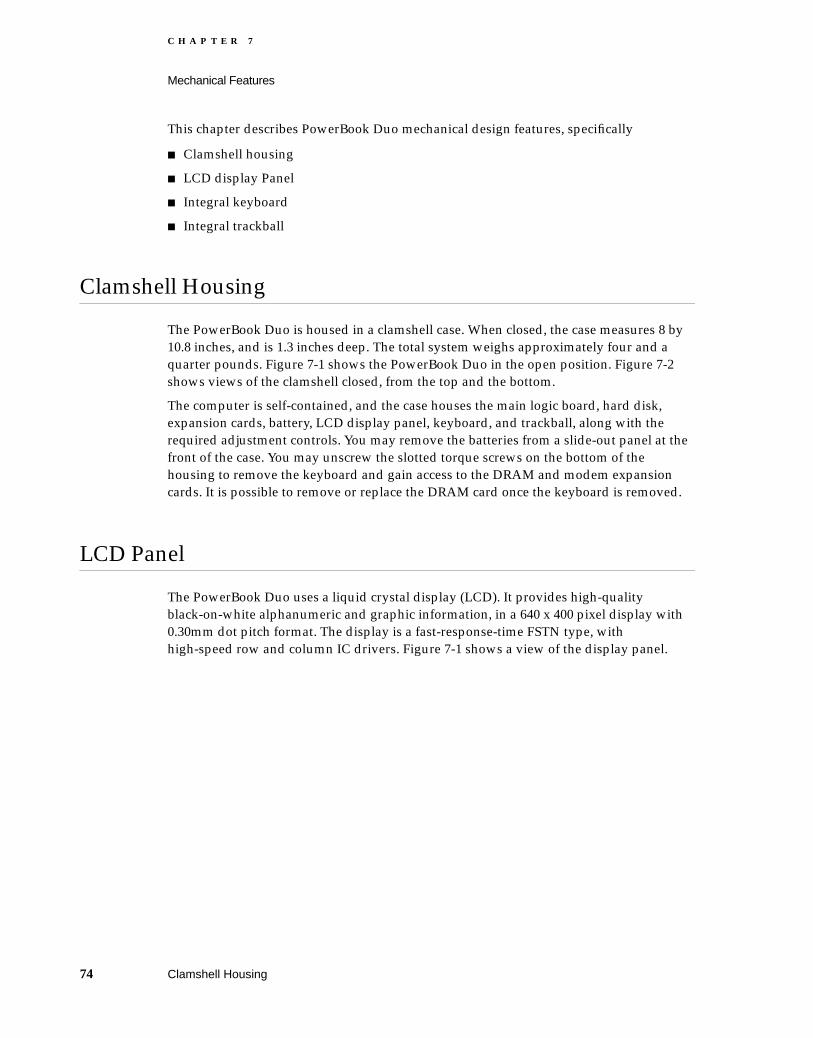
C H A P T E R 7
Mechanical Features
This chapter describes PowerBook Duo mechanical design features, specifically
Clamshell housing
LCD display Panel
Integral keyboard
Integral trackball
Clamshell Housing 7
The PowerBook Duo is housed in a clamshell case. When closed, the case measures 8 by 10.8 inches, and is 1.3 inches deep. The total system weighs approximately four and a quarter pounds. Figure 7-1 shows the PowerBook Duo in the open position. Figure 7-2 shows views of the clamshell closed, from the top and the bottom.
The computer is self-contained, and the case houses the main logic board, hard disk, expansion cards, battery, LCD display panel, keyboard, and trackball, along with the required adjustment controls. You may remove the batteries from a slide-out panel at the front of the case. You may unscrew the slotted torque screws on the bottom of the housing to remove the keyboard and gain access to the DRAM and modem expansion cards. It is possible to remove or replace the DRAM card once the keyboard is removed.
LCD Panel 7
The PowerBook Duo uses a liquid crystal display (LCD). It provides high-quality black-on-white alphanumeric and graphic information, in a 640 x 400 pixel display with 0.30mm dot pitch format. The display is a fast-response-time FSTN type, with high-speed row and column IC drivers. Figure 7-1 shows a view of the display panel.
74 Clamshell Housing
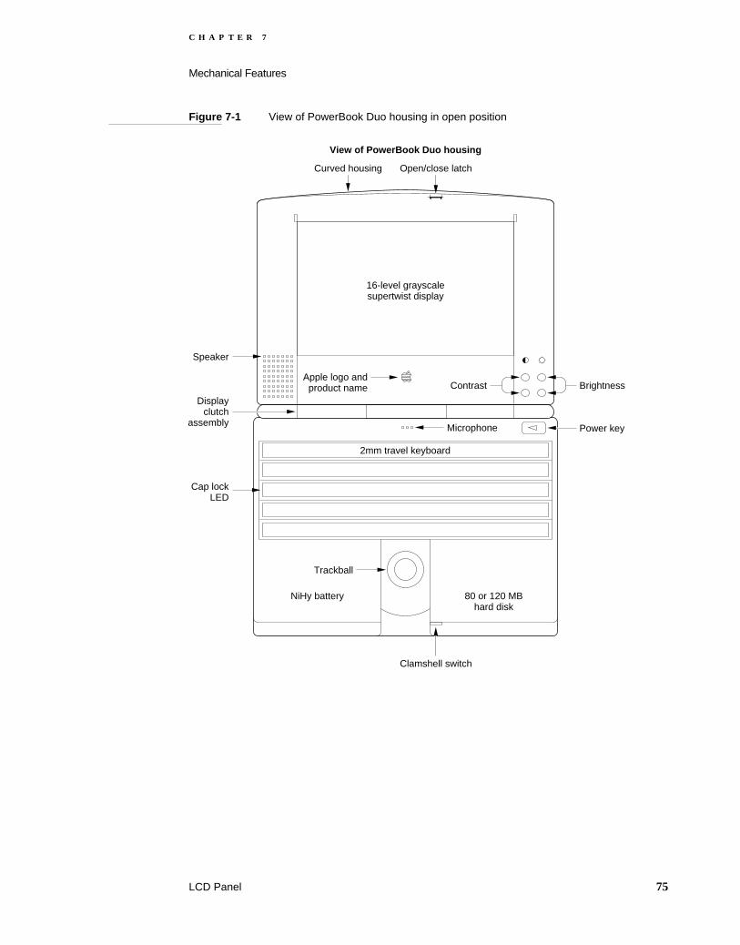
C H A P T E R 7
Mechanical Features
Figure 7-1 View of PowerBook Duo housing in open position
Power key
BrightnessContrast
Microphone
Apple logo andproduct name
16-level grayscalesupertwist display
Open/close latchCurved housing
View of PowerBook Duo housing
Speaker
Displayclutch
assembly
Cap lockLED
NiHy battery 80 or 120 MBhard disk
2mm travel keyboard
Trackball
Clamshell switch
LCD Panel 75

C H A P T E R 7
Mechanical Features
Figure 7-2 Views of PowerBook Duo housing closed
Integral Keyboard 7
The keyboard is an integral part of the PowerBook Duo. The design consists of a light-weight, matrix-only keyboard, of robust design, that operates in a wide range of environments. Two configurations are available. The first is the domestic version, intended for use in the United States. The other is the international keyboard, designed
Rubberbumpers
Top view of Cinnamon housing
Trackball slottedtorque screw
Product label
Slotted torque screws:unscrew to removekeyboard, or installDRAM, or DAA card
Rubber feetminimize slide
Bottom view of Cinnamon housing
Rubberbumpers
Rubberbumpers
Apple logo
76 Integral Keyboard

C H A P T E R 7
Mechanical Features
to meet requirements of European and other overseas markets. The domestic version has 63 keys, the international 64. The two layouts are dimensionally identical, and all keys are momentary. There are differences in the placement of keys, the legends on the keys, and the matrix which must correspond to key placement.
All cosmetic surfaces (the caps for the keys) are of Apple custom design. The keyboard sub-assembly construction is a flat-dished profile with no sculpted keycaps. The mounting details of the sub-assembly with respect to the system are Apple designed, with inputs from the vendor.
Figure 7-3 shows views of both the domestic (upper picture) and international keyboards (lower picture).
Figure 7-3 PowerBook Duo keyboards
Domestic keyboard
International keyboard
Integral Keyboard 77

C H A P T E R 7
Mechanical Features
Integral Trackball 7
The PowerBook Duo trackball is a sub-miniature, low power, optical trackball assembly that fulfills the functions of a mouse. It is located in the center of the keyboard (see Figure 7-1), and is screwed into the computer housing. The assembly includes the trackball mechanism, a removable retainer ring, and two additional switches for trackball button operation. Figure 7-4 shows a graphic view of the trackball assembly.
Figure 7-4 PowerBook Duo trackball assembly
Switch
Trackball
Switch
+Y axis
-Y axis
-X axis +X axis
78 Integral Trackball

C H A P T E R 8
Figure 8-0Listing 8-0Table 8-0
PowerBook Duo Software 8

C H A P T E R 8
PowerBook Duo Software
The PowerBook Duo is a Macintosh, and it has maximum compatibility with current Macintosh applications. It runs on a CPU ROM/system software combination. When you open up the PowerBook Duo and turn it on, the system boots in the same way as other Macintosh systems.
This chapter discusses software modifications and additions that pertain to the basic PowerBook Duo, including
CPU ROM
Declaration ROM (located on bars, and used by the PowerBook Duo for identification)
System software
Fax support
A list of PowerBook Duo software features.
CPU ROM 8
This section describes modifications made to the CPU ROM to support the PowerBook Duo.
Universal ROM Support 8The Universal ROM is a single ROM used in all Macintosh computers since the Macintosh IIci. This ROM contains the operating system for the PowerBook Duo. Overpatches have been added to the base ROM to support the new hardware configuration. This section itemizes those changes which are mainly in the decoder table.
Mouse/Trackball 8There are changes in the mouse/trackball acceleration curves that provide better support for the different characteristics of the mouse and the trackball. A new trap sets the acceleration curves for pointing devices, enabling multiple devices to be handled more efficiently.
Video Driver 8The PowerBook Duo gray-scale video driver supports 1, 2, and 4 bits per pixel.
80 CPU ROM

C H A P T E R 8
PowerBook Duo Software
SCSI Manager 8The external SCSI bus is implemented like that on the Macintosh Quadra 900. The only difference is that the PowerBook Duo uses a C80, and the Macintosh Quadra a C96 SCSI chip.
A feature known as SCSI Disk Mode (SDM) allows you to attach the PowerBook Duo to the Apple Desktop as a simple SCSI device. The computer boots, but displays its SCSI ID on the screen. A software “wire’” connects the internal and external SCSI buses.
After determining that the SCSI Disk Mode cable is plugged in, the system jumps to SDM code, which tracks phase changes on the external SCSI bus and passes them along to the internal bus, so that the built-in hard disk can respond. Data from the internal hard disk is passed back to the host Macintosh.
Declaration ROM 8
The declaration ROM (sometimes referred to as the configuration ROM) is separate from the CPU ROM. It exists in the Macintosh Duo Dock, the Macintosh Duo MiniDock, or in any expansion device requiring ROM support. (The PowerBook Duo Floppy Adapter does not need a declaration ROM.) Among other functions, the declaration ROM enables the PowerBook Duo to recognize the type of expansion device to which it is docked. The declaration ROM is described in the Appendix to this developer note.
System Software 8
This section discusses the system software changes required to support the PowerBook Duo hardware.
PowerBook Control Panel 8The PowerBook Duo has a new control panel. It replaces the current Portable cdev, and is backwards compatible to previous PowerBooks. Only those features supported by the PowerBook Duo appear in the control panel. Similarly, features supported by the PowerBook Duo but not by previous notebooks will not appear in their panels. Figure 8-1 on the next page shows the new PowerBook control panel.
Declaration ROM 81

C H A P T E R 8
PowerBook Duo Software
Figure 8-1 The PowerBook Duo control panel
Clicking Options brings up the Options dialog box shown in Figure 8-2.
Figure 8-2 Options dialog box
Port A AppleTalk 8There is only one serial port (Port A) for the PowerBook Duo when it is operating as a stand-alone computer. This port supports both a high-speed modem and LocalTalk. Changes have been made to route AppleTalk automatically to Port A when the PowerBook Duo is stand-alone.
82 System Software

C H A P T E R 8
PowerBook Duo Software
PowerBook Duo Display Control Panel 8This control panel adds two features to the PowerBook Duo computer.
Screen dimming allows you to dim the backlight on the display screen automatically. This helps to conserve battery power when the computer is not connected to the AC power supply. The feature is a mini screen-saver that actually turns off the backlight on the internal LCD screen, and dims external monitors.
Video Mirroring allows you to have a mirror image of one screen on a second external monitor. If you turn on Video Mirroring, you must restart the computer for the feature to take effect.
Figure 8-3 PowerBook Duo display control panel
AutoRemounter 8The AutoRemounter allows you to remount automatically the file servers that were on the desktop when the computer went into a sleep state, was shutdown, or both. Figure 8-4 shows the control panel for the AutoRemounter.
Figure 8-4 AutoRemounter control panel
Using Remount Shared Disks, you can choose to implement the feature after sleep, after shutdown or sleep, or turn off the feature. When the PowerBook Duo goes into a sleep or shutdown state, the software determines which servers are mounted, and saves the
System Software 83

C H A P T E R 8
PowerBook Duo Software
Volume Control Block information for remounting when the computer wakes up or restarts.
The Connect to Disks By feature allows you to choose whether to be prompted by a password, or to have the server mount automatically, without intervention.
The control panel package contains network sensing code that enables the PowerBook Duo to determine whether or not it is connected to a network. If the computer is not on a network, the software does not try to remount the servers. However, if you later connect to a network, the remounting feature takes effect again.
Data Pump Driver 8The data pump driver is at the lowest end of the modem software. It handles two areas: control and setup; data handling and framing. A single driver supports both areas, and handles Control calls, Read, Write and Status. The driver is fully asynchronous, and supports multiple outstanding calls, cancellation of specific calls, and cancellation of all I/O. The driver is the interface to the hardware, hiding hardware specifics from the upper levels of the modem software.
Fax Support 8
The PowerBook Duo contains software (and hardware) that allows the system to send and receive faxes. The feature is made up of a number of applications that are visible to the user.
Fax View is an application that allows you to view faxes received. Features of Fax View include rotate page, flip vertical, and page scaling.
Fax Cover allows you to create cover pages for faxes.
Fax Monitor enables you to monitor the status of faxes that have been, or are being sent. It functions in much the same way as PrintMonitor.
Fax Sender is a PDEF like other printer drivers. When an application prints, it can “print” to the fax rather than the printer.
In addition to the pieces visible to the user, a fax API is provided for developers. This API allows developers to write software for the low-level fax driver. The Fax Driver is a device manager that communicates between the fax process and the fax hardware. It responds to fax engine calls to send and receive faxes, as well as capabilities requests used in managing the process.
84 Fax Support

C H A P T E R 8
PowerBook Duo Software
Software Features 8
This section is a summary of PowerBook Duo software features.
ROM port
Basic system disk
Multiple SCSI buses. Supports the addition of the Macintosh Duo Dock and other expansion bars that contain their own SCSI connections. (This feature is used only when the PowerBook Duo is operating with an appropriate expansion device.)
SCSI disk mode. Supports the PowerBook Duo as just another hard disk when it is connected to a desktop computer by means of the SCSI chain. (This feature is used only when the PowerBook Duo is operating with an appropriate expansion device.)
Gray-scale LCD driver. Supports 16-level, 1-, 2-, and 4-bit gray scale.
External video driver. Supports up to 16” color display. (This feature is used only when the PowerBook Duo is operating with an appropriate expansion device.)
Floppy driver. Was modified to allow you to attach a floppy drive dynamically, out of sleep. (This feature is used only when the PowerBook Duo is operating with an appropriate expansion device.)
Data pump Toolbox. Interface to a generic data pump, independent of hardware.
Logical docking user experience. Allows you to dock the PowerBook Duo with no confusion or data loss. (This feature is used only when the PowerBook Duo is operating with an appropriate expansion device.)
Fax send/receive application. Built-in capability to send and receive faxes.
Maximum compatibility.
Serial driver replacement. Makes 976, and other applications that are not CTB-aware, work on the PowerBook Duo.
Environment awareness. Ensures proper operation when the PowerBook Duo is docked and undocked. (This feature is used only when the PowerBook Duo is operating with an appropriate expansion device.)
Software Features 85


P A R T T W O
PowerBook Duo Floppy Adapter and Macintosh Duo MiniDock 2


C H A P T E R 9
Figure 9-0Listing 9-0Table 9-0
Introduction to the PowerBook Duo Floppy Adapter and Macintosh Duo MiniDock 9
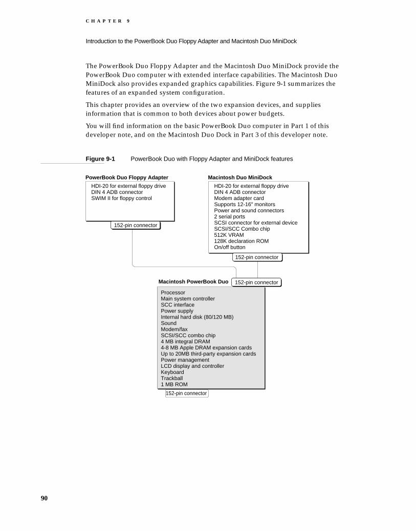
C H A P T E R 9
Introduction to the PowerBook Duo Floppy Adapter and Macintosh Duo MiniDock
The PowerBook Duo Floppy Adapter and the Macintosh Duo MiniDock provide the PowerBook Duo computer with extended interface capabilities. The Macintosh Duo MiniDock also provides expanded graphics capabilities. Figure 9-1 summarizes the features of an expanded system configuration.
This chapter provides an overview of the two expansion devices, and supplies information that is common to both devices about power budgets.
You will find information on the basic PowerBook Duo computer in Part 1 of this developer note, and on the Macintosh Duo Dock in Part 3 of this developer note.
Figure 9-1 PowerBook Duo with Floppy Adapter and MiniDock features
Macintosh PowerBook Duo
ProcessorMain system controllerSCC interfacePower supplyInternal hard disk (80/120 MB)SoundModem/faxSCSI/SCC combo chip4 MB integral DRAM4-8 MB Apple DRAM expansion cardsUp to 20MB third-party expansion cardsPower managementLCD display and controllerKeyboardTrackball1 MB ROM
152-pin connector
HDI-20 for external floppy driveDIN 4 ADB connectorModem adapter cardSupports 12-16" monitorsPower and sound connectors2 serial portsSCSI connector for external deviceSCSI/SCC Combo chip512K VRAM128K declaration ROMOn/off button
HDI-20 for external floppy driveDIN 4 ADB connectorSWIM II for floppy control
PowerBook Duo Floppy Adapter Macintosh Duo MiniDock
152-pin connector
152-pin connector
152-pin connector
90

C H A P T E R 9
Introduction to the PowerBook Duo Floppy Adapter and Macintosh Duo MiniDock
Overview of the PowerBook Duo Floppy Adapter 9
The PowerBook Duo Floppy Adapter is intended for use outside the office. It allows the portable PowerBook Duo to access a floppy disk drive, which it cannot do as a stand-alone computer, and to attach a larger keyboard, or an external pointing device, such as a mouse. These items can be used in place of the PowerBook Duo’s built-in keyboard and trackball. The PowerBook Duo Floppy Adapter hardware features are described in greater detail in Chapter 10, “PowerBook Duo Floppy Adapter Hardware.”
PowerBook Duo Floppy Adapter features include the following:
High-density interface connector (HDI-20) for an external floppy-disk drive.
Built-in Super Woz Integrated Machine (SWIM II) chip, to control the external floppy drive.
Mini-DIN 4 Apple Desktop Bus (ADB) connector for mouse or external keyboard.
152-pin connector that mates to the PowerBook Duo.
Guide pins to align the PowerBook Duo Floppy Adapter connector with the PowerBook Duo connector.
Mechanical locking device to secure the PowerBook Duo Floppy Adapter to the computer.
Overview of the Macintosh Duo MiniDock 9
The Macintosh Duo MiniDock implements a number of I/O features that enhance the performance of the PowerBook Duo in an office environment. They include external sound input/output, two serial ports, one SCSI connector for external SCSI devices, and one floppy connector for an external floppy-disk drive. The foremost enhancement is built-in video support for 12-inch monochrome and RGB monitors, the 13-inch RGB monitor, the 15-inch monochrome portrait monitor, and the new 16-inch RGB monitor with pixel depths up to 8 bits. The MiniDock also allows the PowerBook Duo to access a hard disk drive. The Duo MiniDock supports a floppy disk drive, in the same way as the PowerBook Duo Floppy Adapter, and similarly enables use of an external keyboard and pointing device. The Macintosh Duo MiniDock is described in more detail in Chapter 11, “Macintosh Duo Mini Dock Hardware.”
Macintosh Duo MiniDock features include the following:
High-density interface connector (HDI-20) for an external floppy disk drive.
Integrated Super Woz Integrated Machine (SWIM II) chip, to control the external floppy drive.
Mini-DIN-4 Apple Desktop Bus (ADB) connector for mouse or external keyboard.
High density interface SCSI connector (HDI-30) for an external hard disk.
Overview of the PowerBook Duo Floppy Adapter 91

C H A P T E R 9
Introduction to the PowerBook Duo Floppy Adapter and Macintosh Duo MiniDock
Two mini DIN-8 serial port connectors to implement the SCC interface.
Built-in control for SCSI and SCC interface through the SCSI/SCC combo chip.
DB-15 external video connector to support external monitors.
Video controller and video RAM to support expanded video capabilities.
Power jack to provide interface for the external wall-mounted recharge/power adapter.
RJ-11 (domestic) or a mini DIN-8 (international) modem connector.
Two sound connectors: one for input and one for output.
152-pin connector that mates to the PowerBook Duo.
Guide pins to align the Macintosh Duo MiniDock connector with the PowerBook Duo connector.
Mechanical locking device to secure the Macintosh Duo MiniDock to the computer.
Power Budget 9
Power budget considerations are the same for the Floppy Adapter and the MiniDock. Table 9-1 shows the power supplied to either expansion device under four different conditions. The power budgets for conditions 1 and 2 are identical.
Condition 1 assumes battery operation, +5 V and -5 V from the PowerBook Duo expansion connector, and no voltage regulator in the device.
Condition 2 assumes AC adapter operation, +5 V and -5 V from the PowerBook Duo expansion connector, and no voltage regulator in the device.
Condition 3 assumes AC battery operation, +5 V and -5 V from the PowerBook Duo expansion connector, and voltage regulator in the device.
Condition 4 assumes AC adapter operation, +5 V and -5 V from the PowerBook Duo expansion connector, and voltage regulator in the device.
* 5.0 W maximum using Apple’s standard power adapter
Table 9-1 Expansion device power budget
ConditionPower from +5 V pins
Power from -5 V pins
Power from +24 V pins to voltage reg.
1 2.0W 0.15W 0.0W
2 2.0W 0.15W 0.0W
3 2.0W 0.15W 2.8W
4 2.0W 0.15W 5.0W*
92 Power Budget

C H A P T E R 9
Introduction to the PowerBook Duo Floppy Adapter and Macintosh Duo MiniDock
If the expansion device requires more power than that delivered by the +5 V and -5 V inputs, power must be derived from the +24 V input via the voltage regulator.
Electrical Considerations 9
To reduce electro-magnetic emissions, careful attention must be paid to the electrical design of the PowerBook Duo Floppy Adapter and Macintosh Duo MiniDock logic boards, and to the mechanical design of the cases. Ferrite beads filter power supply signals from the PowerBook Duo computer. RC (resistor-capacitor) networks on connector signals reduce high-frequency noise. Using series termination for all long multiple-loaded signal paths reduces reflection. Case design incorporates shielded connectors and EMI (electro-magnetic interference) shields to minimize radiation.
Thermal Considerations 9
The Macintosh Duo MiniDock design currently provides no venting. All heat dissipation is accomplished with conduction and radiation cooling. The case design and component layout on the logic board distribute power dissipation to minimize hot spots. Some internal components may be heat-sinked to the case by providing an internal boss which drops down to touch the component. Although the thermal impedance of the plastic case material is high, this process reduces the internal ambient temperature considerably.
The PowerBook Duo Floppy Adapter similarly has no venting. However, since this device has so few components, heat dissipation is not a problem.
Electrical Considerations 93


C H A P T E R 1 0
Figure 10-0Listing 10-0Table 10-0
PowerBook Duo Floppy Adapter Hardware 10

C H A P T E R 1 0
PowerBook Duo Floppy Adapter Hardware
The PowerBook Duo Floppy Adapter provides the PowerBook Duo with support for a 1.44MB floppy drive, and an Apple Desktop Bus interface to accommodate an external keyboard and mouse. This chapter covers the following topics:
Floppy Adapter housing
Interfacing with the PowerBook Duo
Floppy Adapter main logic board
Apple Desktop Bus interface
Floppy disk drive interface
Power supply
PowerBook Duo Floppy Adapter Housing 10
Figure 10-1 shows different views of the PowerBook Duo Floppy Adapter housing.
Interface with the PowerBook Duo 10
The PowerBook Duo Floppy Adapter connects to PowerBook Duo by means of a 152-pin, custom, right-angle connector, referred to as the main expansion connector, JAE part number JX20-152BA-D1LT-H. It is mounted directly on the logic board, and plugs into the 152-pin connector on the PowerBook Duo rear panel.
The connector gives the Floppy Adapter direct access to the microprocessor’s 32-bit address bus, 32-bit data bus, and control signals. It also provides access to power, control, and status signals in other parts of the computer.
96 PowerBook Duo Floppy Adapter Housing

C H A P T E R 1 0
PowerBook Duo Floppy Adapter Hardware
Figure 10-1 Views of PowerBook Duo Floppy Adapter
The signal assignments for the main expansion connector are listed in Table 4-1, in Part 1 of this developer note. Table 10-1 lists the subset of signals used for the Floppy Adapter. All other signals are not connected. A slash in front of a signal name (/PLUG IN) indicates an active-low signal.
Releasebutton
Security cable hole.Locks PowerBook Duo in place when the FloppyAdapter is attached to security cable.
HDI-30 floppyconnector
Mini-DIN-4 ADBconnector
PowerBook Duo Floppy Adapter top view
Floppy Adapter side view
Locking mechanism: pull up, thenpush down on lever to lock Floppy Adapter to PowerBook Duo
Mini-DIN-4 ADBconnector
HDI-30 floppyconnector
PowerBook Duo Floppy Adapter rear view
Interface with the PowerBook Duo 97
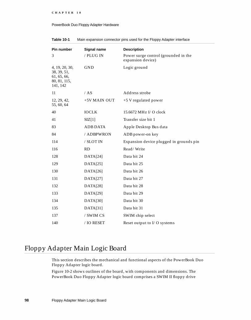
C H A P T E R 1 0
PowerBook Duo Floppy Adapter Hardware
Floppy Adapter Main Logic Board 10
This section describes the mechanical and functional aspects of the PowerBook Duo Floppy Adapter logic board.
Figure 10-2 shows outlines of the board, with components and dimensions. The PowerBook Duo Floppy Adapter logic board comprises a SWIM II floppy drive
Table 10-1 Main expansion connector pins used for the Floppy Adapter interface
Pin number Signal name Description
3 /PLUG IN Power surge control (grounded in the expansion device)
4, 19, 20, 30, 38, 39, 51, 61, 65, 66, 80, 81, 115, 141, 142
GND Logic ground
11 /AS Address strobe
12, 29, 42, 55, 60, 64
+5V MAIN OUT +5 V regulated power
40 IOCLK 15.6672 MHz I/O clock
41 SIZ[1] Transfer size bit 1
83 ADB DATA Apple Desktop Bus data
84 /ADBPWRON ADB power-on key
114 /SLOT IN Expansion device plugged in grounds pin
116 RD Read/Write
128 DATA[24] Data bit 24
129 DATA[25] Data bit 25
130 DATA[26] Data bit 26
131 DATA[27] Data bit 27
132 DATA[28] Data bit 28
133 DATA[29] Data bit 29
134 DATA[30] Data bit 30
135 DATA[31] Data bit 31
137 /SWIM CS SWIM chip select
140 /IO RESET Reset output to I/O systems
98 Floppy Adapter Main Logic Board

C H A P T E R 1 0
PowerBook Duo Floppy Adapter Hardware
controller, connector for the floppy drive, an ADB connector, and ferrites to limit EMI (electromagnetic interference), and ESD (electro-static discharge) suppressors.
Figure 10-2 Outlines of the PowerBook Duo Floppy Adapter logic board with components and dimensions
Figure 10-3 is a block diagram of the PowerBook Duo Floppy Adapter logic board functions. The logic board provides the facility to attach a floppy drive to the PowerBook Duo. It also routes the ADB signals from the 152-pin main expansion connector to the ADB connector.
SWIM II chip ADB port
Ferrites
152-pin expansion connector
0.2" (5.08 mm)
0.8" (20.32 mm)
3.5" (88.90 mm)
0.6" (15.24 mm)
0.75" (19.05 mm)
0.9" (22.86 mm)
1" (25.40 mm)
1.2" (30.48 mm)
0.5" (12.70 mm)
Floppy port
Floppy Adapter Main Logic Board 99
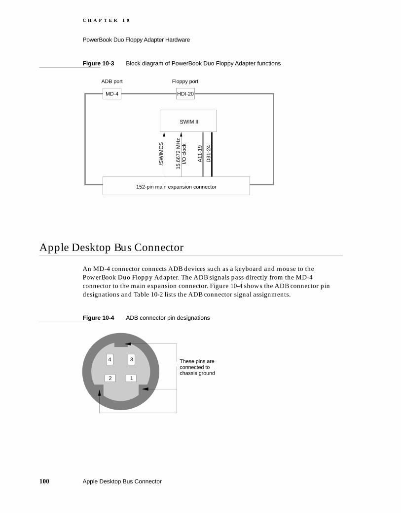
C H A P T E R 1 0
PowerBook Duo Floppy Adapter Hardware
Figure 10-3 Block diagram of PowerBook Duo Floppy Adapter functions
Apple Desktop Bus Connector 10
An MD-4 connector connects ADB devices such as a keyboard and mouse to the PowerBook Duo Floppy Adapter. The ADB signals pass directly from the MD-4 connector to the main expansion connector. Figure 10-4 shows the ADB connector pin designations and Table 10-2 lists the ADB connector signal assignments.
Figure 10-4 ADB connector pin designations
152-pin main expansion connector
MD-4 HDI-20
Floppy portADB port
SWIM II
/SW
IMC
S
15.6
672
MH
z I/O
clo
ck
A11
-19
D31
-24
These pins are connected to chassis ground
3
2 1
4
100 Apple Desktop Bus Connector

C H A P T E R 1 0
PowerBook Duo Floppy Adapter Hardware
Support for Floppy Disk Drive 10
The PowerBook Duo Floppy Adapter enables a floppy disk drive to be connected to the PowerBook Duo computer. The drive is connected through a custom HDI-20 high-density connector. Pin designations for this connector are shown in Figure 10-5, and the signal assignments in Table 10-3. Control for the floppy drive is implemented by a single proprietary ASIC (application specific IC), SWIM II.
Figure 10-5 Floppy disk drive connector pin designations
Table 10-2 ADB connector signal assignments
Pin number Signal name Description
1 ADB Bidirectional data bus for input and output.
2 /POWER ON Key on ADB keyboard grounds this pin to pin 4 to turn on power supply
3 +5V +5 V power.
4 GND Ground
5 4 3 2 1
10
15
20
9 8 7 6
14 13 12 11
19 18 17 16
Support for Floppy Disk Drive 101

C H A P T E R 1 0
PowerBook Duo Floppy Adapter Hardware
Power Supply 10
The PowerBook Duo Floppy Adapter contains no power circuitry. It is powered from regulated supplies in the PowerBook Duo.
Table 10-3 Floppy disk drive connector signal assignments
Pin number Signal name Description
1, 2, 3, 4 GND Ground
5, 10, 20 nc No connection
6, 7, 8, 9 +5V +5 V power for floppy drive
11 PH0 State-control line 0
12 PH1 State-control line 1
13 PH2 State-control line 2
14 PH3 State-control line 3
15 /WRREQ Write data request
16 HDSEL Head select
17 /ENBL Floppy drive enable
18 RD Read data
19 WR Write data
102 Power Supply

C H A P T E R 1 1
Figure 11-0Listing 11-0Table 11-0
Macintosh Duo MiniDock Hardware 11

C H A P T E R 1 1
Macintosh Duo MiniDock Hardware
The Macintosh Duo MiniDock provides the PowerBook Duo with an extended interface to the outside world as well as expanded graphics capabilities. This chapter covers the following topics:
MiniDock housing
Docking constraints
Interfacing with the PowerBook Duo
MiniDock main logic board
Support for video features
The floppy disk drive interface
The SCSI interface
Serial I/O interface
Apple Desktop Bus interface
Audio ports
The declaration ROM
Power sources
The modem adapter card
Designing a Macintosh Duo MiniDock 11
The Macintosh Duo MiniDock is particularly interesting to third-party developers who wish to tailor functions of the PowerBook Duo to meet specific market demands, for example
to accelerate computer performance
to support a variety of video configurations
to support Ethernet
to support DOS applications
Although different features may be designed into the MiniDock, you must stay within the physical and electrical constraints of the Apple-designed Duo MiniDock described in this developer note.
Macintosh Duo MiniDock Housing 11
Figure 11-1 shows various views of the Apple Macintosh Duo MiniDock, with its rear-panel I/O connectors, and locking mechanism.
104 Designing a Macintosh Duo MiniDock
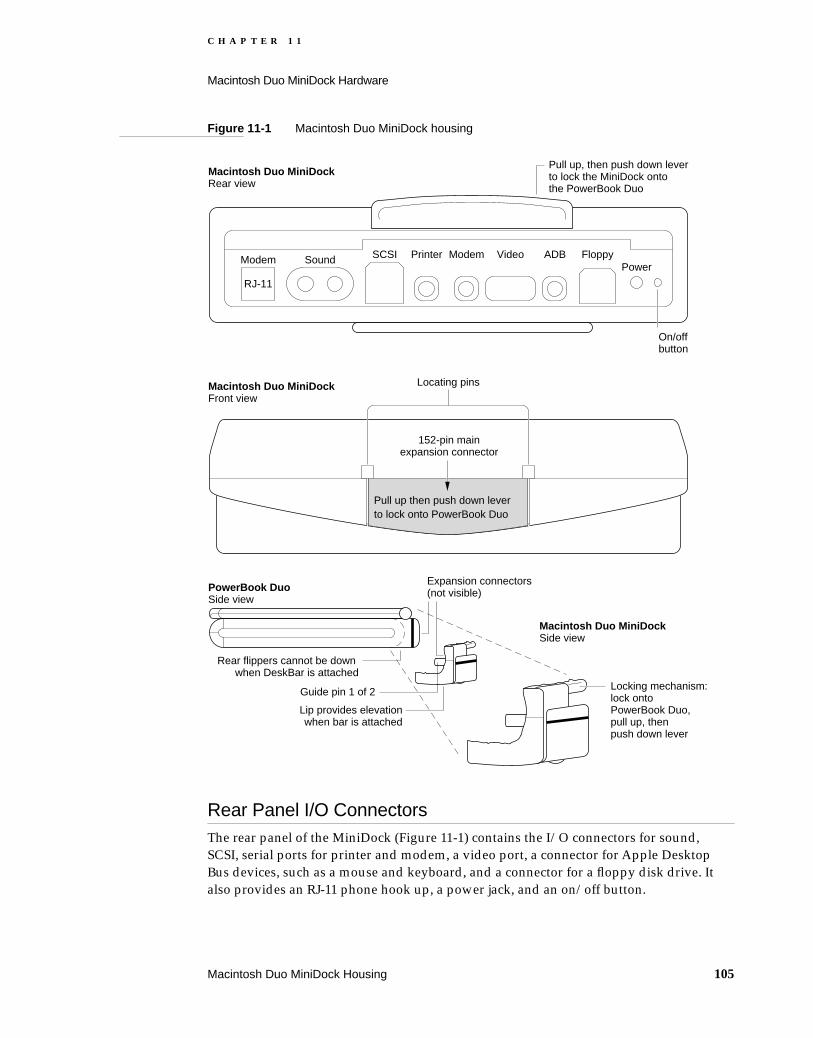
C H A P T E R 1 1
Macintosh Duo MiniDock Hardware
Figure 11-1 Macintosh Duo MiniDock housing
Rear Panel I/O Connectors 11The rear panel of the MiniDock (Figure 11-1) contains the I/O connectors for sound, SCSI, serial ports for printer and modem, a video port, a connector for Apple Desktop Bus devices, such as a mouse and keyboard, and a connector for a floppy disk drive. It also provides an RJ-11 phone hook up, a power jack, and an on/off button.
Modem
Macintosh Duo MiniDock Rear view
RJ-11
Sound SCSI Printer Modem Video ADB FloppyPower
On/offbutton
Pull up, then push down leverto lock the MiniDock onto the PowerBook Duo
Locating pinsMacintosh Duo MiniDock Front view
PowerBook Duo Side view
Macintosh Duo MiniDock Side view
Rear flippers cannot be down when DeskBar is attached
Lip provides elevationwhen bar is attached
Locking mechanism:lock onto PowerBook Duo,pull up, then push down lever
152-pin mainexpansion connector
Expansion connectors(not visible)
Guide pin 1 of 2
Pull up then push down lever to lock onto PowerBook Duo
Macintosh Duo MiniDock Housing 105

C H A P T E R 1 1
Macintosh Duo MiniDock Hardware
Locking Mechanism 11The MiniDock connects to the PowerBook Duo by means of a 152-pin expansion connector. Two guide pins on the MiniDock align it with holes on the rear panel of the PowerBook Duo, and make sure that the expansion connectors are aligned correctly, and the MiniDock is properly seated. The MiniDock has a locking mechanism. As the guide pins on the MiniDock are inserted into the guide holes on the PowerBook Duo, latches on the MiniDock’s locking mechanism latch into the computer. Pressure on the locking mechanism handle secures the MiniDock to the computer.
Docking Constraints 11
Chapter 12, “Software Issues for the Floppy Adapter and MiniDock,” discusses docking constraints for the Macintosh Duo MiniDock.
IMPORTANT
You should attach the Macintosh Duo MiniDock to the PowerBook Duo only when the computer is off or asleep. If the PowerBook Duo is already docked to the Macintosh Duo MiniDock, it cannot be put to sleep while any external SCSI devices are in use.
Interface with the Powerbook Duo 11
The Macintosh Duo MiniDock plugs into the 152-pin connector on the PowerBook Duo rear panel. This connector accepts a maximum insertion load of 28 pounds when the MiniDock is plugged into it. The connector is designed to withstand approximately 5000 lifetime insertions/extractions. Specifications for shear force and twisting resistance are not yet available.
The mating connector for the Macintosh Duo MiniDock is not mounted directly to the logic board, since it must connect to the PowerBook Duo at an angle of 83 degrees, and be mounted well above the board. The connector is therefore mounted on a separate logic board using a flex printed circuit. The connector is JAE part number JX20-152BA-DIST-H.
You will find the signal assignments for the main expansion connector in Table 4-1, in Chapter 4 of this publication. Table 11-1 lists the subset of signals used for the Duo MiniDock. All other signals are not connected. A slash in front of a signal name (/AS) indicates an active-low signal.
106 Docking Constraints

C H A P T E R 1 1
Macintosh Duo MiniDock Hardware
Table 11-1 Main expansion connector signals used for the Duo MiniDock interface
Pin number Signal name Description
1, 2, 77, 78, 79
PR +24V EXT Raw +24 V from AC adapter
3 /PLUG IN Power surge control (grounded in the expansion device)
4, 19, 20, 30, 38, 39, 51, 61, 65, 66, 80, 81, 115, 141, 142
GND Logic ground
5, 6, 82 PR MAIN BAT POS Positive battery power output
7 /ON/OFF OUT On/off button
11 /AS Address strobe
12, 29, 42, 55, 60, 64
+5V MAIN OUT +5 V regulated power
21 ADDR[0] Address bit 0
22 ADDR[2] Address bit 2
23 ADDR[4] Address bit 4
24 ADDR[6] Address bit 6
25 ADDR[8] Address bit 8
26 ADDR[10] Address bit 10
27 ADDR[12] Address bit 12
28 ADDR[14] Address bit 14
31 ADDR[18] Address bit 18
32 ADDR[20] Address bit 20
33 ADDR[22] Address bit 22
34 ADDR[24] Address bit 24
35 ADDR[26] Address bit 26
36 ADDR[28] Address bit 28
37 ADDR[30] Address bit 30
40 IOCLK 15.6672 MHz I/O clock
41 SIZ[1] Transfer size bit 1
52 DATA[17] Data bit 17
53 DATA[18] Data bit 18
54 DATA[19] Data bit 19
Interface with the Powerbook Duo 107
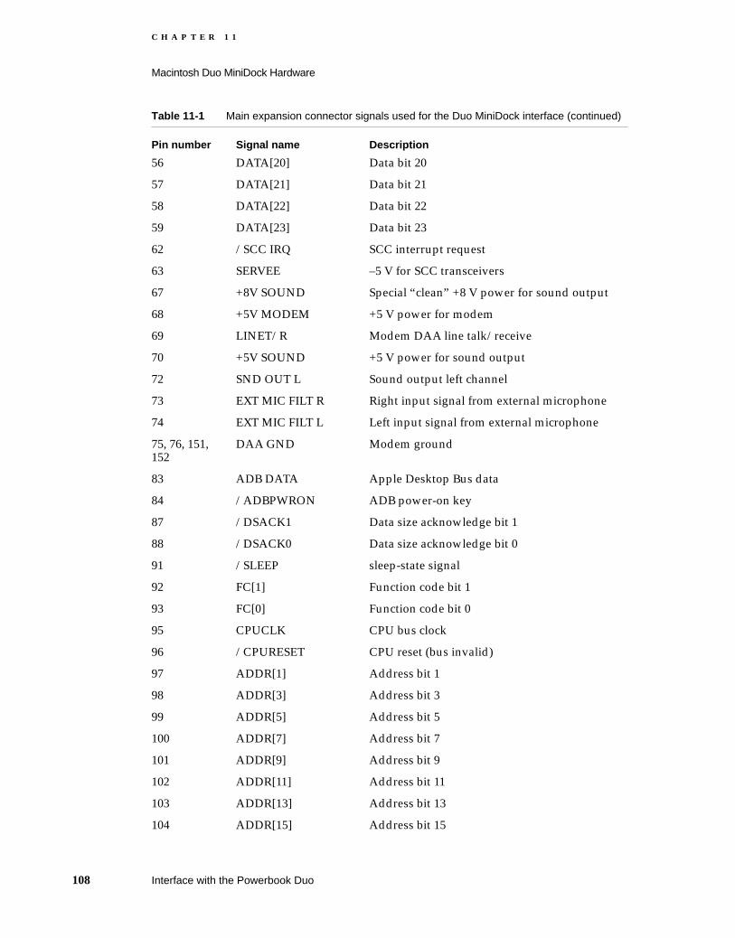
C H A P T E R 1 1
Macintosh Duo MiniDock Hardware
56 DATA[20] Data bit 20
57 DATA[21] Data bit 21
58 DATA[22] Data bit 22
59 DATA[23] Data bit 23
62 /SCC IRQ SCC interrupt request
63 SERVEE –5 V for SCC transceivers
67 +8V SOUND Special “clean” +8 V power for sound output
68 +5V MODEM +5 V power for modem
69 LINET/R Modem DAA line talk/receive
70 +5V SOUND +5 V power for sound output
72 SND OUT L Sound output left channel
73 EXT MIC FILT R Right input signal from external microphone
74 EXT MIC FILT L Left input signal from external microphone
75, 76, 151, 152
DAA GND Modem ground
83 ADB DATA Apple Desktop Bus data
84 /ADBPWRON ADB power-on key
87 /DSACK1 Data size acknowledge bit 1
88 /DSACK0 Data size acknowledge bit 0
91 /SLEEP sleep-state signal
92 FC[1] Function code bit 1
93 FC[0] Function code bit 0
95 CPUCLK CPU bus clock
96 /CPURESET CPU reset (bus invalid)
97 ADDR[1] Address bit 1
98 ADDR[3] Address bit 3
99 ADDR[5] Address bit 5
100 ADDR[7] Address bit 7
101 ADDR[9] Address bit 9
102 ADDR[11] Address bit 11
103 ADDR[13] Address bit 13
104 ADDR[15] Address bit 15
Table 11-1 Main expansion connector signals used for the Duo MiniDock interface (continued)
Pin number Signal name Description
108 Interface with the Powerbook Duo

C H A P T E R 1 1
Macintosh Duo MiniDock Hardware
105 ADDR[16] Address bit 16
106 ADDR[17] Address bit 17
107 ADDR[19] Address bit 19
108 ADDR[21] Address bit 21
109 ADDR[23] Address bit 23
110 ADDR[25] Address bit 25
111 ADDR[27] Address bit 27
112 ADDR[29] Address bit 29
113 ADDR[31] Address bit 31
114 /SLOT IN When the expansion device is plugged in, this pin is grounded
116 RD Read/write
117 SIZ[0] Transfer size bit 0
122 +5VEXT SENSE
+5 V external sense
127 DATA[16] Data bit 16
128 DATA[24] Data bit 24
129 DATA[25] Data bit 25
130 DATA[26] Data bit 26
131 DATA[27] Data bit 27
132 DATA[28] Data bit 28
133 DATA[29] Data bit 29
134 DATA[30] Data bit 30
135 DATA[31] Data bit 31
137 /SWIM CS SWIM chip select
138 /SLOT E IRQ Pseudo-NuBus expansion slot E interrupt
139 /PFW Power fail warning (shutdown bit)
140 /IO RESET Reset output to I/O systems
143 DAA CNTLF Modem DAA control
144 DAA ID IN ID input from 152-pin connector to modem card
145 /RING DET Ring detect signal from the modem DAA
146 /RB DVR Modem relay B driver
Table 11-1 Main expansion connector signals used for the Duo MiniDock interface (continued)
Pin number Signal name Description
Interface with the Powerbook Duo 109

C H A P T E R 1 1
Macintosh Duo MiniDock Hardware
Duo MiniDock Main Logic Board 11
All the logic required to implement Macintosh Duo MiniDock functions is housed on a single printed-circuit board. This section provides mechanical specifications for the logic board. Figure 11-2 shows the outline of the board with major components. Figure 11-3 shows a view of the Macintosh Duo MiniDock logic board, with dimensions. Macintosh Duo MiniDock design provides space for a logic board approximately 8.07" (205 mm) long by 2.8" (71 mm) wide. Length is increased a further 1.5" (38 mm) if the modem DAA is not used. Component height on the board should not exceed 0.93" (23 mm).
Figure 11-4 is a functional block diagram of the Duo MiniDock logic board. Subsequent sections describe each of the logic blocks, and provide interface specifications where applicable.
147 /RA DVR Modem relay A driver
148 EXT MIC SEL External microphone plugged in
150 /SPKR SEL External speaker plugged in
Table 11-1 Main expansion connector signals used for the Duo MiniDock interface (continued)
Pin number Signal name Description
110 Duo MiniDock Main Logic Board
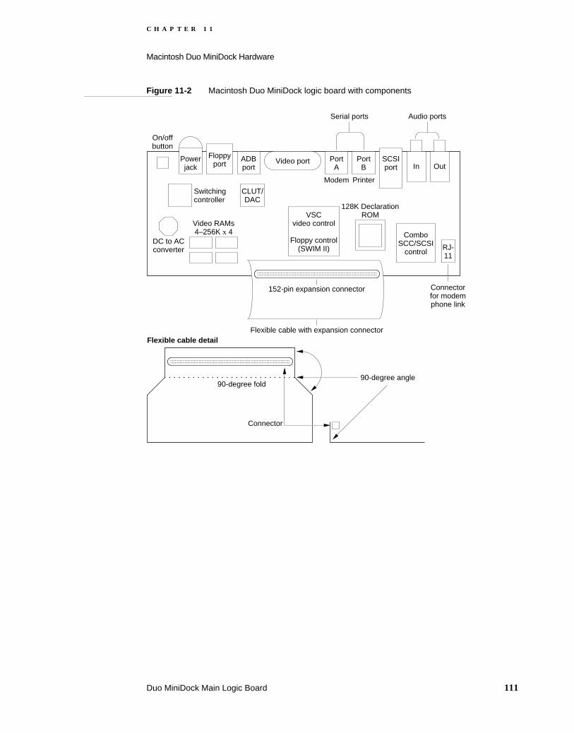
C H A P T E R 1 1
Macintosh Duo MiniDock Hardware
Figure 11-2 Macintosh Duo MiniDock logic board with components
ADBport
Floppyport
Powerjack
On/offbutton
Video port PortA
PortB
SCSIport In Out
Switchingcontroller
CLUT/DAC
DC to ACconverter
VSCvideo control
Floppy control(SWIM II)
128K DeclarationROM
RJ-11
Video RAMs4–256K x 4 Combo
SCC/SCSIcontrol
Audio portsSerial ports
Connectorfor modemphone link
Flexible cable with expansion connector
152-pin expansion connector
90-degree angle90-degree fold
Flexible cable detail
Connector
Modem Printer
Duo MiniDock Main Logic Board 111
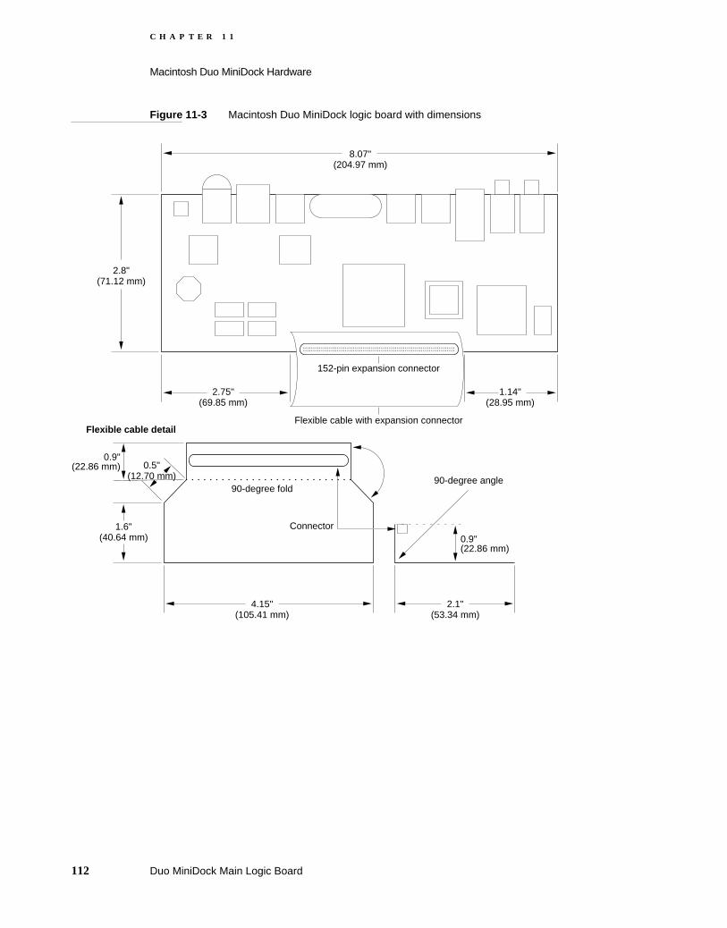
C H A P T E R 1 1
Macintosh Duo MiniDock Hardware
Figure 11-3 Macintosh Duo MiniDock logic board with dimensions
90-degree angle90-degree fold
Flexible cable detail
Connector
2.8" (71.12 mm)
8.07" (204.97 mm)
2.75" (69.85 mm)
1.14" (28.95 mm)
1.6" (40.64 mm)
0.9" (22.86 mm) 0.5"
(12.70 mm)
4.15" (105.41 mm)
2.1" (53.34 mm)
0.9" (22.86 mm)
Flexible cable with expansion connector
152-pin expansion connector
112 Duo MiniDock Main Logic Board

C H A P T E R 1 1
Macintosh Duo MiniDock Hardware
Figure 11-4 Block diagram of Macintosh Duo MiniDock functions
Support for Video Features 11
This section describes the enhanced video features provided by the Mini Dock’s video subsystem controller, video RAM, and video output circuitry. It also describes the video interface.
RJ-11
Modem
DAA
ADB On/off Sound
Out DB-15
Video Floppy
HDI-20
A
MD-8
BSerial ports
HDI-30
SCSIport
MD-8
CLUT/DAC
VRAM256Kx16
Declar.ROM
VSCI/O &Video
SWIM II
Combo
SCC SCSI
PLL15-60MHZ
Barpowersupply
D31
-24
152-pin JAE main expansion connector32-bit data, 32-bit address
A6-
4, 1
,0
CP
U C
lock
I/O C
lock
D31
-24
A31
-0
D31
-16
D31
-24
D31
-24
A16
-0
A31
-0
D31
-0
15-60 Mhz dot clk
*
******
I/O Clock = 15.6672 MhzCPU Clock = 33.3333 Mhz
* 15.6672 Mhz** 2-30 Mhz*** 15.6672 Mhz**** 3.672 Mhz
MD-4 SWPower In
Support for Video Features 113
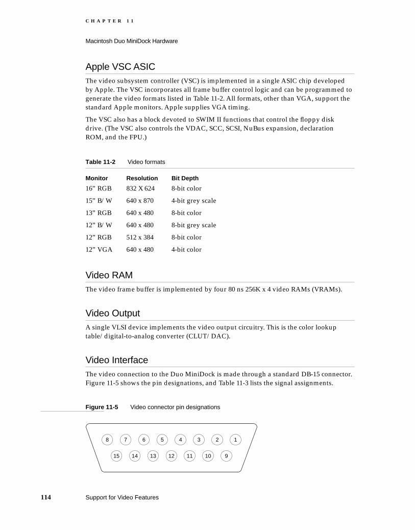
C H A P T E R 1 1
Macintosh Duo MiniDock Hardware
Apple VSC ASIC 11The video subsystem controller (VSC) is implemented in a single ASIC chip developed by Apple. The VSC incorporates all frame buffer control logic and can be programmed to generate the video formats listed in Table 11-2. All formats, other than VGA, support the standard Apple monitors. Apple supplies VGA timing.
The VSC also has a block devoted to SWIM II functions that control the floppy disk drive. (The VSC also controls the VDAC, SCC, SCSI, NuBus expansion, declaration ROM, and the FPU.)
Video RAM 11The video frame buffer is implemented by four 80 ns 256K x 4 video RAMs (VRAMs).
Video Output 11A single VLSI device implements the video output circuitry. This is the color lookup table/digital-to-analog converter (CLUT/DAC).
Video Interface 11The video connection to the Duo MiniDock is made through a standard DB-15 connector. Figure 11-5 shows the pin designations, and Table 11-3 lists the signal assignments.
Figure 11-5 Video connector pin designations
Table 11-2 Video formats
Monitor Resolution Bit Depth
16” RGB 832 X 624 8-bit color
15” B/W 640 x 870 4-bit grey scale
13” RGB 640 x 480 8-bit color
12” B/W 640 x 480 8-bit grey scale
12” RGB 512 x 384 8-bit color
12” VGA 640 x 480 4-bit color
8 7 6 5 4 3 2 1
15 14 13 12 11 10 9
114 Support for Video Features

C H A P T E R 1 1
Macintosh Duo MiniDock Hardware
Support for Floppy Disk Drive 11
This section describes the support provided by the MiniDock for floppy disk drives.
SWIM II Controller 11A standard cell block in the VSC implements SWIM II functions to control floppy disk drive functions.
Table 11-3 Video connector signal assignments
Pin number Signal name Description
1 RED GND Red ground
2 RED VID Red video signal
3 /CSYNC Composite sync
4 SENSE0 Monitor sense bit 0
5 GRN VID Green video signal
6 GRN GND Green ground
7 SENSE1 Monitor sense bit 1
8 NC No connection
9 BLU VID Blue video signal
10 SENSE2 Monitor sense bit 2
11 C&VSYNC GND Ground for CSYNC and VSYNC
12 /VSYNC Vertical sync
13 BLU GND Blue ground
14 HSYNC GND HSYNC ground
15 /HSYNC Horizontal sync
Support for Floppy Disk Drive 115

C H A P T E R 1 1
Macintosh Duo MiniDock Hardware
Floppy Disk Drive Interface 11The Macintosh Duo MiniDock provides the PowerBook Duo with access to a floppy disk drive. The connector is a custom HDI-20 high-density connector. Figure 11-6 shows the pin designations and Table 11-4 the signal assignments.
Figure 11-6 Floppy disk drive connector pin designations
Table 11-4 Floppy disk drive connector signal assignments
Pin number Signal name Description
1, 2, 3, 4 GND Ground
5, 10, 20 nc No connection
6, 7, 8, 9 +5V +5 V power for floppy drive
11 PH0 State-control line 0
12 PH1 State-control line 1
13 PH2 State-control line 2
14 PH3 State-control line 3
15 /WRREQ Write data request
16 HDSEL Head select
17 /ENBL Floppy drive enable
18 RD Read data
19 WR Write data
5 4 3 2 1
10
15
20
9 8 7 6
14 13 12 11
19 18 17 16
116 Support for Floppy Disk Drive

C H A P T E R 1 1
Macintosh Duo MiniDock Hardware
Support for SCSI Devices 11
The Macintosh Duo MiniDock uses an 85C80 Combo chip to support the SCSI channel interface.
It also provides an HDI-30 SCSI connector that enables hard drives, CD ROMs, and other peripheral devices to be connected to the computer. The pin designations for the SCSI connector are shown in Figure 11-7, and the signal assignments in Table 11-5.
Figure 11-7 SCSI connector pin designations
Table 11-5 SCSI connector signal assignments
Pin number Signal name Description
1 SCSI DM SCSI disk mode sense. Grounded in special SCSI disk mode cable.
2 /DB0 Bit 0 of SCSI data bus
3, 8, 10, 12, 13, 15, 17, 20, 22, 24
GND Ground
4 /DB1 Bit 1 of SCSI data bus
30 29 28 27 26 25
24 23 22 21 20 19
18 17 16 15 14 13
12 11 10 9 8 7
6 5 4 3 2 1
Support for SCSI Devices 117

C H A P T E R 1 1
Macintosh Duo MiniDock Hardware
Serial I/O Support 11
The Combo chip supports two serial ports, which are used for serial input and output. The inputs and outputs are buffered and converted to RS-422 logic levels, using Apple custom driver/receiver chips.
The serial port connectors are eight-pin miniature DIN connectors. Figure 11-8 shows the pin designations for the connector, and Table 11-6 lists the signal assignments. The table indicates to which pins on the SCC Combo chip the serial port signals are connected.
5 TPWR +5 V terminator power
6 /DB2 Bit 2 of SCSI data bus
7 /DB3 Bit 3 of SCSI data bus
9 /ACK Handshake signal. Acknowledges a request for data transfer.
11 /DB4 Bit 4 of SCSI data bus
14 /DB5 Bit 5 of SCSI data bus
16 /DB6 Bit 6 of SCSI data bus
18 /DB7 Bit 7 of SCSI data bus
19 /DB8 Bit 8 of SCSI data bus
21 /REQ Request for a data transfer
23 /BSY When active (low) indicates that the SCSI data bus is busy.
25 /ATN When active (low) indicates an attention condition.
26 /C/D When active (low) indicates that data is on the SCSI bus. When high, indicates that control signals are on the bus.
27 /RST SCSI bus reset
28 /MSG Indicates the message phase.
29 /SEL Selects between target and initiator.
30 /I/O Controls the direction of data movement. When low data is output. When high, data is input.
Table 11-5 SCSI connector signal assignments (continued)
Pin number Signal name Description
118 Serial I/O Support

C H A P T E R 1 1
Macintosh Duo MiniDock Hardware
Figure 11-8 Serial port connector pin designations
Apple Desktop Bus Connector 11
An MD-4 connector on the MiniDock rear panel provides the PowerBook Duo with access to devices such as an external keyboard and mouse. The ADB signals pass directly from the MD-4 connector to the main 152-pin expansion connector. Figure 11-9 shows the pin designations for this connector, and Table 11-7 lists the signal assignments.
Table 11-6 Serial port connector signal assignments
Pin number Signal name Description
1 HSKo Handshake output. Connected to the Request to Send (RTS) pin on the Combo chip. Tristated when DataTerminal Ready (DTR) signal is inactive.
2 HSKi Handshake input. Connected to the Transmit Receive Clock (TRXC) pin on the Combo chip.
3 /TXD Transmit data (inverted). Connected to the Transmit Data (TXD) pin on the Combo chip. Tristated when DTR is inactive
4 SG Signal ground. Connected to logic and chassis ground.
5 /RXD Receive data (inverted). Connected to the Receive Data (RXD) pin on the Combo chip.
6 TXD Transmit data. Connected to the Transmit Data (TXD) pin on the Combo chip. Tristated when DTR is inactive.
7 GPi General purpose input. Connected to the Data Carrier Detect (DCD) pin on the Combo chip.
8 RXD Receive data. Connected to the Receive Data (RXD) pin on the Combo chip.
9, 10, 11 GND These pins are connected to chassis ground.
1
34
8
5
7 6
2
These pins are connected to chassis ground
Apple Desktop Bus Connector 119

C H A P T E R 1 1
Macintosh Duo MiniDock Hardware
Figure 11-9 ADB connector pin designations
Audio Ports 11
Two mini-jacks provide connections for sound input and sound output.
Declaration ROM 11
The 128KB declaration ROM contains information about configuration, driver, and diagnostics. It enables the PowerBook Duo to identify the type of MiniDock with which it is operating, as well as performing a variety of other functions. The ROM is similar in function and configuration to the one used on NuBus cards.
The ROM is a surface-mount part that is soldered onto the logic board. Chapter 15, “Software Issues for the Duo Dock,” provides further information on the MiniDock declaration ROM. The Appendix, “Declaration ROM Specifications,” contains the full specification for the PowerBook Duo declaration ROM.
Table 11-7 ADB connector signal assignments
Pin number Signal name Description
1 ADB Bidirectional data bus for input and output
2 POWER ON Key on ADB keyboard (if connected) grounds this pin to pin 4, enabling power to be turned on from the keyboard
3 +5V +5 V power
4 GND Ground
These pins are connected to chassis ground
3
2 1
4
120 Audio Ports

C H A P T E R 1 1
Macintosh Duo MiniDock Hardware
NoteSome Apple publications refer to the declaration ROM as the configuration ROM.
Power Sources 11
The Macintosh Duo MiniDock receives raw unregulated battery power from the PowerBook Duo via the 152-pin connector. A DC-to-DC switching converter regulates battery power to +5 VDC, for use by some of the components on the logic board. Many of the components are powered from the regulated +5 V supply from the PowerBook Duo. An on-board switching controller regulates voltage, and supplies power for the SCSI terminator, the floppy drive, and ADB devices. Table 11-8 summarizes the power sources for each Macintosh Duo MiniDock subsystem.
A three-pin power jack connects the Macintosh Duo MiniDock to an AC adapter. The three conductors (power, ground, and ADB signal) pass through the MiniDock directly to the 152-pin main expansion connector.
Modem Adapter Card 11
The PowerBook Duo has an integral modem and RJ-11 phone hookup. When the computer is plugged into the MiniDock, the RJ-11 connector is blocked. The MiniDock uses an adapter card, that plugs into a 10-pin connector on the side of its main logic
Table 11-8 Power sources for Macintosh Duo MiniDock subsystems
Subsystem Power source
Combo chip (SCSI/SCC) PowerBook Duo main power
Serial drivers PowerBook Duo main, PowerBook Duo VEE
EPROM PowerBook Duo main power
Floppy drive Macintosh Duo MiniDock - switching controller
Sound-out buffer PowerBook Duo +5 V sound
Sound-in buffer PowerBook Duo +5 V sound, +8 V sound
Video PowerBook Duo main
SCSI terminator Macintosh Duo MiniDock - switching controller
DAA PowerBook Duo +5 V modem
ADB Macintosh Duo MiniDock - switching controller
Power Sources 121

C H A P T E R 1 1
Macintosh Duo MiniDock Hardware
board, and provides a phone hookup on the rear panel of the MiniDock. Table 11-9 lists the signal assignments for the 10-pin connector. Figure 11-10 shows an outline of the adapter card.
Figure 11-10 Modem adapter card
Table 11-9 Modem adapter card connector signal assignments
Pin number Signal name Description
1 LINET/R Modem DAA line talk/receive
2, 3, 4 DAA GND Modem DAA ground
5 /RA DVR Modem relay A driver
6 DAA ID DAA identification
7 /RING DET Ring detect signal
8 /RB DVR Modem relay B driver
9 DAA CNTRL Modem DAA control
10 +5V MODEM +5 V power for modem
10 pinconnectorplugs intoMiniDock
connector
RJ-11 phone hook up fordomestic version or mini-DIN-8for International version
0.1875" (4.76 mm)
1.32"(33.33 mm)
2.75"(69.85 mm)
0.1563"(3.97 mm)
Modemadapter card
122 Modem Adapter Card

C H A P T E R 1 2
Figure 12-0Listing 12-0Table 12-0
Software Issues for the Floppy Adapter and the MiniDock 12

C H A P T E R 1 2
Software Issues for the Floppy Adapter and the MiniDock
This chapter discusses software issues raised when docking the PowerBook Duo to the PowerBook Duo Floppy Adapter, or the Macintosh Duo MiniDock. Topics covered include:
Docking and undocking the PowerBook Duo: conditions and constraints
Preference and information identities
Multiple environments: desktop and notebook
Moving from a single- to a multiple-port environment
System software modifications
Declaration ROM functions
Modifications to system ROM functions
Docking and Undocking the PowerBook Duo 12
The process of attaching the PowerBook Duo to an expansion device is referred to as docking . Removing the computer from an expansion device is called undocking .
This section describes docking and undocking procedures and conditions, and the constraints placed on external devices, such as keyboards, floppy and hard disk drives, when the computer is docked or undocked.
Docking Conditions 12The PowerBook Duo computer exists in one of three possible states: off, operational, and asleep. Docking and undocking is perfectly safe when the computer is turned off. If the computer is operational when docked, it will go into shutdown and restart. Behavior varies if the computer is docked when it is in the sleep state. The following section describe the conditions that occur while docking and undocking the PowerBook Duo. Table 12-1 summarizes those conditions.
Docking Constraints 12There are three basic docking constraints for which new dialog boxes have been developed.
You may attach an expansion device such as the Floppy Adapter or MiniDock to the PowerBook Duo only when the machine is asleep or off. Once the computer is attached, you may then add ADB devices, such as the mouse and/or keyboard, floppy-disk drive, and monitor. As soon as the computer emerges from the sleep state, the attached floppy drive, mouse and keyboard, and monitor are available for use.
124 Docking and Undocking the PowerBook Duo
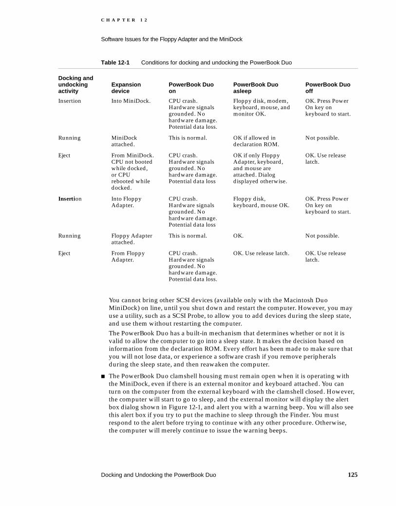
C H A P T E R 1 2
Software Issues for the Floppy Adapter and the MiniDock
You cannot bring other SCSI devices (available only with the Macintosh Duo MiniDock) on line, until you shut down and restart the computer. However, you may use a utility, such as a SCSI Probe, to allow you to add devices during the sleep state, and use them without restarting the computer. The PowerBook Duo has a built-in mechanism that determines whether or not it is valid to allow the computer to go into a sleep state. It makes the decision based on information from the declaration ROM. Every effort has been made to make sure that you will not lose data, or experience a software crash if you remove peripherals during the sleep state, and then reawaken the computer.
The PowerBook Duo clamshell housing must remain open when it is operating with the MiniDock, even if there is an external monitor and keyboard attached. You can turn on the computer from the external keyboard with the clamshell closed. However, the computer will start to go to sleep, and the external monitor will display the alert box dialog shown in Figure 12-1, and alert you with a warning beep. You will also see this alert box if you try to put the machine to sleep through the Finder. You must respond to the alert before trying to continue with any other procedure. Otherwise, the computer will merely continue to issue the warning beeps.
Table 12-1 Conditions for docking and undocking the PowerBook Duo
Docking and undocking activity
Expansion device
PowerBook Duo on
PowerBook Duo asleep
PowerBook Duo off
Insertion Into MiniDock. CPU crash. Hardware signals grounded. No hardware damage. Potential data loss.
Floppy disk, modem, keyboard, mouse, and monitor OK.
OK. Press Power On key on keyboard to start.
Running MiniDock attached.
This is normal. OK if allowed in declaration ROM.
Not possible.
Eject From MiniDock. CPU not booted while docked, or CPU rebooted while docked.
CPU crash. Hardware signals grounded. No hardware damage. Potential data loss
OK if only Floppy Adapter, keyboard, and mouse are attached. Dialog displayed otherwise.
OK. Use release latch.
Insertion Into Floppy Adapter.
CPU crash. Hardware signals grounded. No hardware damage. Potential data loss
Floppy disk, keyboard, mouse OK.
OK. Press Power On key on keyboard to start.
Running Floppy Adapter attached.
This is normal. OK. Not possible.
Eject From Floppy Adapter.
CPU crash. Hardware signals grounded. No hardware damage. Potential data loss.
OK. Use release latch. OK. Use release latch.
Docking and Undocking the PowerBook Duo 125
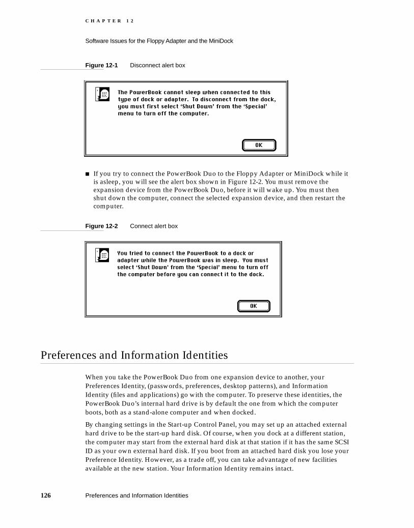
C H A P T E R 1 2
Software Issues for the Floppy Adapter and the MiniDock
Figure 12-1 Disconnect alert box
If you try to connect the PowerBook Duo to the Floppy Adapter or MiniDock while it is asleep, you will see the alert box shown in Figure 12-2. You must remove the expansion device from the PowerBook Duo, before it will wake up. You must then shut down the computer, connect the selected expansion device, and then restart the computer.
Figure 12-2 Connect alert box
Preferences and Information Identities 12
When you take the PowerBook Duo from one expansion device to another, your Preferences Identity, (passwords, preferences, desktop patterns), and Information Identity (files and applications) go with the computer. To preserve these identities, the PowerBook Duo’s internal hard drive is by default the one from which the computer boots, both as a stand-alone computer and when docked.
By changing settings in the Start-up Control Panel, you may set up an attached external hard drive to be the start-up hard disk. Of course, when you dock at a different station, the computer may start from the external hard disk at that station if it has the same SCSI ID as your own external hard disk. If you boot from an attached hard disk you lose your Preference Identity. However, as a trade off, you can take advantage of new facilities available at the new station. Your Information Identity remains intact.
126 Preferences and Information Identities

C H A P T E R 1 2
Software Issues for the Floppy Adapter and the MiniDock
Multiple Environments 12
The PowerBook Duo is the first Macintosh designed for use both as a notebook and as a desktop computer. The system software accommodates the multiple environments by providing mechanisms to determine the characteristics of the environment, and modifies internal settings to accommodate movement. Areas most affected are monitors and file-server connections.
Monitors 12When you dock the PowerBook Duo to the Duo MiniDock, or any third-party device that supports video, you may use an external monitor, or continue to use the integral LCD display. By default, the internal LCD display is the main screen when the PowerBook Duo first docks to the Duo MiniDock. Undocking and redocking (conditions that require a restart) cause the MiniDock settings to take effect.
File-Server Connections 12The PowerBook Duo institutes auto-remounting, a process in which a server is remounted when the computer is put to sleep or shut down, and reawakens or is rebooted, while attached to a network. If any files are open on a server when the PowerBook Duo tries to go to sleep, you are warned that data may be lost, and are prompted to close or save the files before allowing the computer to go to sleep. Once the files are closed, you may safely close file-server connections. The connection information is stored, and connections reestablished when the computer wakes up. You have the option of being prompted for a password before remounting, or having remounting occur automatically. You set the option through the Remounter Control Panel.
Single to Multiple Ports 12
When the PowerBook Duo is used as a stand-alone computer, it has only one serial port (A). You may use this port for LocalTalk (printer hook up) or high-speed modem. When the computer is docked to the Duo MiniDock, this port is covered by one of the computer’s feet, which slides up over the port to make way for the Macintosh Duo MiniDock connector.
The Duo MiniDock provides you with two serial ports (A and B). Arbitration is needed to change from a single- to a dual-port configuration. There are two scenarios.
The printer is connected to Port B using the LocalTalk, and Port A is used for a high-speed modem. The software makes the changes needed, and you do not have to go into the Chooser to specify that the printer is in Port B. This is the only scenario if you wish to connect both a printer and a modem.
Multiple Environments 127
C H A P T E R 1 2
Software Issues for the Floppy Adapter and the MiniDock
The printer is connected to Port A. The modem cannot be plugged into Port B, since the PowerBook Duo cannot define the functionality of the port based upon what is plugged into it.
Overview of Declaration ROM Functions 12
Certain firmware must be included on the logic board of each expansion device in the MiniDock category. This firmware is stored in a ROM area called the declaration ROM, and it enables the computer to distinguish between the different types of expansion devices. The code required to support special services resides on the device, relieving the system ROM of the need to recognize each and every configuration.
The PowerBook Duo Floppy Adapter does not require a declaration ROM, since its functions do not influence the functionality of the overall system. The presence of the floppy disk drive plugged into the Floppy Adapter is detected by the presence of the sense signal on pin 114 of the main expansion connector.
To provide the flexibility needed to support many configurations, the PowerBook Duo design takes the Slot Manager model, used by NuBus cards, as the software interface. The structure of the PowerBook Duo’s declaration ROM is based on the structure of the declaration ROM designed for NuBus cards. Chapter 8 of Designing Cards and Drivers for the Macintosh Family, Third Edition, is crucial for an understanding of generic declaration ROM issues and ideas. The Appendix of this developer note, “Declaration ROM Specifications,” discusses issues relating to the overall Macintosh Duo System.
NoteThe declaration ROM is alternatively called the configuration ROM in some Apple publications.
Overview of Modified System ROM Functions 12
This section talks about certain system ROM functions that relate specifically to the presence or absence of an expansion device in the MiniDock category. The system ROM checks the state of such docking devices at two points: when it is starting up in the normal boot process, and when it is coming out of sleep. These two processes are similar, and involve installing a handler for a particular device. The process becomes more complex if, during the sleep state, one device is taken out and replaced by another.
Start-Up Process 12Under normal conditions, when you start up the PowerBook Duo, the system ROM goes through the docking management process, soon after the Slot Manager is initialized. The system ROM looks for a slot resource (sResource) on the Duo MiniDock’s logic board. When sResource is verified, the system ROM copies the contents of the declaration
128 Overview of Declaration ROM Functions
C H A P T E R 1 2
Software Issues for the Floppy Adapter and the MiniDock
ROM’s sResource into the system heap, and replaces the Docking Dispatch trap handler with the address of the new handler. The docking handling code is physically located in a code block in the declaration ROM, and once the system ROM has installed this code block in the heap, dock handling calls can be made as required. In fact, the system ROM makes the init-selector call to allow the Duo MiniDock logic board to initialize itself.
Wake-Up Process 12When the computer is coming out of sleep state, the system ROM is concerned with conditions that might have changed during sleep state. The ROM tracks the presence of an expansion device through the presence of the board ID, an entry in the board’s sResource, stored in the device declaration ROM. By checking this entry, the system ROM can determine if conditions have remained the same, if a device has been removed, and if a new device has been installed.
If conditions are the same, the system ROM takes no action. If a device has been removed or a different device has been installed, the system ROM instructs the old docking handler, which still resides in the system heap, to clean up after itself. When this process is complete, the old handler is purged, and a new handler replaces it. If a device has simply been removed, a default “no device” handler replaces the old entry.
From this point, the wake-up process follows the same path as the start-up process. Functionality may be limited when the computer is coming out of sleep state. For example, video and network services are not available from the newly-added device, and the computer must be restarted for those functions to come into effect.
Overview of Modified System ROM Functions 129


P A R T T H R E E
Macintosh Duo Dock 3


C H A P T E R 1 3
Figure 13-0Listing 13-0Table 13-0
Introduction to the Macintosh Duo Dock 13
C H A P T E R 1 3
Introduction to the Macintosh Duo Dock
The Macintosh Duo Dock provides the PowerBook Duo computer with the capabilities of a desktop computer. This chapter provides an overview of the Macintosh Duo Dock features. You will find information about the basic PowerBook Duo computer in Part 1 of this developer note.
Overview of the Macintosh Duo Dock 13
The Macintosh Duo Dock turns the PowerBook Duo into a fully functional desk-top computer. It has an internal floppy-disk drive, and an optional internal hard-disk drive. Its extended interface accommodates a variety of peripherals, including external SCSI devices, mouse, keyboard, modem, printer, and sound I/O. Enhanced graphics capabilities support 12- to 16-inch monitors. The Macintosh Duo Dock provides a NuBus adapter card with slots for two NuBus cards. To enhance overall system performance, the main logic board provides a socket for a 68882 math coprocessor (floating-point unit).
It is easy to dock and undock the PowerBook Duo. Assisted by a motorized insert/eject mechanism, it slides into a slot on the front of the Macintosh Duo Dock. A security key locks the PowerBook Duo in the Macintosh Duo Dock, and locks out other CPUs when the Macintosh Duo Dock is not occupied. Since the Macintosh Duo Dock housing can support the weight of a 16” monitor, it has a comparatively small footprint.
Macintosh Duo Dock features include the following:
Macintosh I/O: external HDI-30 SCSI connector, mini-DIN 4 Apple Desktop Bus (ADB) connector for mouse or external keyboard, two serial communication ports for modem and printer, monaural sound input and output, on/off switch
Built-in speaker
152-pin connector that mates to the PowerBook Duo
Motorized eject/inject mechanism for reliable connections
Internal 1.4 MB super-drive floppy, with auto-insert and auto-eject mechanism
Internal 50-pin SCSI connector for optional hard disk drive, integral bay for 3.5-inch by 1-inch hard disk drive
Video port for external monitor: 12 inches up to 16-inches, at 8 bits per pixel standard
VGA and SVGA support for color monitors
Optional VRAM SIMM (single in-line memory module) for 16-bit color on 12- or 16-inch monitor
A NuBus adapter card with slots for two full-sized 15 watt NuBus cards, or one 25W card
PLCC socket for a 33 MHz 68882 math coprocessor (FPU)
A security key to lock the PowerBook Duo in Macintosh Duo Dock
75 W power supply with switched AC outlet for monitor power
A modem adapter card to connect the PowerBook Duo modem to phone line
134 Overview of the Macintosh Duo Dock
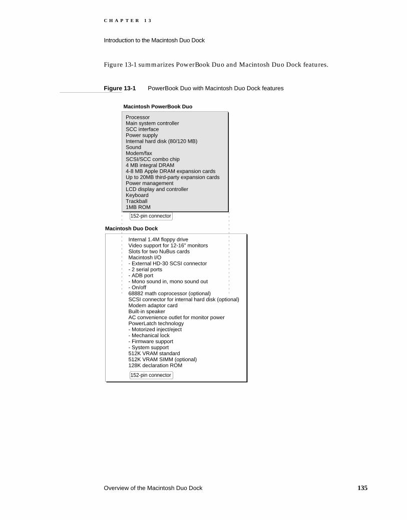
C H A P T E R 1 3
Introduction to the Macintosh Duo Dock
Figure 13-1 summarizes PowerBook Duo and Macintosh Duo Dock features.
Figure 13-1 PowerBook Duo with Macintosh Duo Dock features
Internal 1.4M floppy driveVideo support for 12-16" monitorsSlots for two NuBus cardsMacintosh I/O- External HD-30 SCSI connector- 2 serial ports- ADB port- Mono sound in, mono sound out- On/off68882 math coprocessor (optional)SCSI connector for internal hard disk (optional)Modem adaptor cardBuilt-in speakerAC convenience outlet for monitor powerPowerLatch technology- Motorized inject/eject- Mechanical lock- Firmware support- System support512K VRAM standard512K VRAM SIMM (optional)128K declaration ROM
152-pin connector
Macintosh PowerBook Duo
ProcessorMain system controllerSCC interfacePower supplyInternal hard disk (80/120 MB)SoundModem/faxSCSI/SCC combo chip4 MB integral DRAM4-8 MB Apple DRAM expansion cardsUp to 20MB third-party expansion cardsPower managementLCD display and controllerKeyboardTrackball1MB ROM
Macintosh Duo Dock
152-pin connector
Overview of the Macintosh Duo Dock 135


C H A P T E R 1 4
Figure 14-0Listing 14-0Table 14-0
Macintosh Duo Dock Hardware 14

C H A P T E R 1 4
Macintosh Duo Dock Hardware
The Macintosh Duo Dock is of interest to third-party developers who wish to expand PowerBook Duo capabilities in terms of performance, access to additional peripherals, monitor size, video capability, and storage capacity. This chapter outlines the guidelines applied to the design of the Macintosh Duo Dock hardware. This chapter covers the following topics:
Duo Dock housing
PowerLatch technology
Power capabilities: power supply, pass-through power for monitor, power for the PowerBook Duo computer
Macintosh Duo Dock interface to the PowerBook Duo computer
Modem adapter card, RJ-11 modem port
HDI-20 floppy disk drive connector
On-board 50-pin SCSI connector and power connector for optional hard drive
Mechanical and functional characteristics of the main logic board
Video support: video subsystem controller, VRAM, VRAM expansion, video output, and video port
SCSI interface: external HDI-30 SCSI connector for external hard disk, or other SCSI devices
Serial ports and interface: two mini-DIN 8 serial ports to implement the SCC feature
A mini-DIN 4 ADB connector to connect Apple DeskTop devices, such as the mouse and keyboard
Sound input and output ports
NuBus expansion capabilities: connector and two slots for optional NuBus cards
Floating point capability: socket for optional 33 MHz, PLCC 68882 floating-point unit
Reserved I/O connector space
Declaration ROM 14
The PowerBook Duo computer operates with a variety of expansion devices, including the Macintosh Duo Dock. A 128 KB declaration ROM, surface mounted on the Macintosh Duo Dock main logic board, contains configuration, driver, and diagnostics information. The ROM enables the PowerBook Duo computer to identify the type of expansion device with which it is operating. It also performs a variety of other functions. The ROM is similar in function and configuration to the one used on NuBus boards. The Appendix, “Declaration ROM Specifications,” provides more information about the declaration ROM.
NoteYou must install a declaration ROM on the Macintosh Duo Dock main logic board.
138 Declaration ROM

C H A P T E R 1 4
Macintosh Duo Dock Hardware
NoteSome Apple documentation refers to the declaration ROM as the configuration ROM.
Docking Constraints 14
Chapter 15, “Software Issues for the Duo Dock,” discusses docking constraints for the Macintosh Duo Dock.
IMPORTANT
You should attach the Macintosh Duo Dock to the PowerBook Duo computer only when the computer is off, and all files and applications are inactive. If you try to dock the PowerBook Duo while it is asleep, you will not lose data, but you will have to shut down and restart to activate features. If the PowerBook Duo is already docked to the Macintosh Duo Dock, it cannot be put to sleep.
Macintosh Duo Dock Housing 14
Figure 14-1, Figure 14-2, and Figure 14-3 show various views of the Macintosh Duo Dock. It is 16.37 inches (415.6 mm) deep, 12.75 inches (323.8 mm) wide, and 4.75 inches (120.5 mm high). It weighs 19 pounds. The shell houses the Macintosh Duo Dock main logic board, a 152-pin expansion connector, a modem adapter card, an internal floppy disk drive, a power supply, a speaker, and a rear connector panel. It also provides a bay for an internal hard disk drive, and slots for two NuBus cards.
As indicated in Figure 14-1, the PowerBook Duo computer slides into a slot in the front of the Macintosh Duo Dock. When the PowerBook Duo is inserted into the slot, power is applied to the motor mechanism, the PowerBook Duo is drawn into the Macintosh Duo Dock, and connects automatically to the 152-pin connector at the rear of the Macintosh Duo Dock housing. When the eject button is depressed and the system is off, the PowerBook Duo is automatically ejected from the Macintosh Duo Dock. If the system is running when you try to eject, you will be prompted to save changed files, shut down, and then eject. A manual eject mechanism ejects the PowerBook Duo from the station when power is not available. These functions, among others, are implemented by the PowerLatch technology described later in this chapter.
As a security feature, the Macintosh Duo Dock has a locking mechanism (Figure 14-2), with 125 unique locks. The PowerBook Duo is locked in place by turning the key from the 6 o’clock to the 3 o’clock position. This mechanism also prevents the PowerBook Duo from being inserted into the Macintosh Duo Dock.
To reduce electromagnetic emissions, careful attention is paid to the mechanical design of the housing. Housing design incorporates shielded connectors and EMI shields to minimize radiation.
Docking Constraints 139
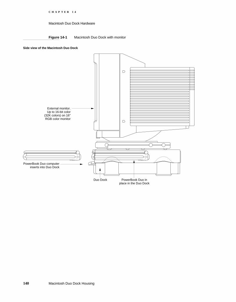
C H A P T E R 1 4
Macintosh Duo Dock Hardware
Figure 14-1 Macintosh Duo Dock with monitor
External monitor. Up to 16-bit color
(32K colors) on 16" RGB color monitor
PowerBook Duo computer inserts into Duo Dock
Duo Dock PowerBook Duo in place in the Duo Dock
Side view of the Macintosh Duo Dock
140 Macintosh Duo Dock Housing

C H A P T E R 1 4
Macintosh Duo Dock Hardware
Figure 14-2 Side views of Macintosh Duo Dock
Right side
Left side
Apple extended keyboard fits here when fully extended.
PowerBook Duoinserts here
Top supports up to 50 pounds. This is the approximate weight of a 16" monitor. Two steel bars go across the top and transfer the load to the support feet.
Optional 1/3 high, 1" x 3.5"hard drive goes here.
Floppy drive
Support feet
Power supplyvents
Manual eject for ejecting the PowerBook Duowhen there is no power; use the key in this holeto eject; manual eject does not work whenPowerBook Duo is locked in the Duo Dock.
Security key locks PowerBook Duo intothe Duo Dock. The security key alsolocks PowerBook Duo out of the Duo Dock.
Macintosh Duo Dock Housing 141

C H A P T E R 1 4
Macintosh Duo Dock Hardware
Figure 14-3 Rear and front views of Macintosh Duo Dock
Front view
Rear view
Speaker
Electrical eject button
RJ-11modem port
Soundout
HDI-30SCSI Plastic plug
for future upgrade
Serialports DB-15
video
ADBPoweron/off
Security cable hole2 NuBus slots
in
Power plug
Monitor powerpass through
K
142 Macintosh Duo Dock Housing
C H A P T E R 1 4
Macintosh Duo Dock Hardware
PowerLatch Technology 14
Apple’s PowerLatch technology provides the user with seamless integration between desk-top and portable computer environments. The technology comprises the hardware, firmware, and software support needed to attach the PowerBook Duo computer to the Macintosh Duo Dock. PowerLatch provides the following capabilities:
Physical docking connections, including the automatic inject/eject feature, and the locking mechanism.
Firmware support in the form of ASICs and ROM, and low-level software. These elements enable the PowerBook Duo computer to recognize the environment in which it is operating, specifically whether it is operating as a stand-alone computer, or is docked in the Macintosh Duo Dock.
system software which automatically configures the system for each environment, for example, automatically remounting shared disks when the user returns to the Macintosh Duo Dock.
Interface to the PowerBook Duo 14
A 152-pin main expansion connector, JAE part number JX20-152BA-D1LTH, provides the interface between the PowerBook Duo computer, and the Macintosh Duo Dock. It mounts directly to the Duo Dock’s main logic board, and plugs into the matching connector on the PowerBook Duo rear panel, giving the Duo Dock direct access to the microprocessor’s 32-bit address bus, 32-bit data bus, and control signals. It also provides access to power, control, and status signals in other parts of the computer, and allows the Duo Dock to provide power to the PowerBook Duo.
The connector accepts a maximum insertion load of 28 pounds when an expansion device is plugged into it. It is designed to withstand approximately 5000 lifetime insertions, and based on current testing, has a tolerance for misalignment of nine thousandths of an inch. Two holes, one on each side of the connector, serve as receptacles for guide pins.
Table 4-1 in Chapter 4 of this developer note lists the signal assignments for the connector. Table 14-1 lists the subset of signals used for the Duo Dock interface. A slash before a signal name (/AS) indicates an active-low signal.
PowerLatch Technology 143

C H A P T E R 1 4
Macintosh Duo Dock Hardware
Table 14-1 Main expansion connector signals used for the Duo Dock interface
Pin number Signal name Description
1, 2, 77, 78, 79
PR +24V EXT Raw +24 V from AC adapter
3 /PLUG IN Power surge control (grounded in the expansion device)
4, 19, 20, 30, 38, 39, 51, 61, 65, 66, 80, 81, 115, 141, 142
GND Logic ground
7 /ON/OFF OUT On/off button
9 /STERM Synchronous termination
10 /DS Data strobe
11 /AS Address strobe
12, 29, 42, +5V MAIN OUT +5 V regulated power
13 /HALT Halt
14 /BERR Bus error
15 /BGACK Bus grant acknowledge
21 ADDR[0] Address bit 0
22 ADDR[2] Address bit 2
23 ADDR[4] Address bit 4
24 ADDR[6] Address bit 6
25 ADDR[8] Address bit 8
26 ADDR[10] Address bit 10
27 ADDR[12] Address bit 12
28 ADDR[14] Address bit 14
31 ADDR[18] Address bit 18
32 ADDR[20] Address bit 20
33 ADDR[22] Address bit 22
34 ADDR[24] Address bit 24
35 ADDR[26] Address bit 26
36 ADDR[28] Address bit 28
37 ADDR[30] Address bit 30
40 IOCLK 15.6672 MHz I/O clock
144 Interface to the PowerBook Duo

C H A P T E R 1 4
Macintosh Duo Dock Hardware
41 SIZ[1] Transfer size bit 1
43 DATA[0] Data bit 0
44 DATA[1] Data bit 1
45 DATA[2] Data bit 2
46 DATA[3] Data bit 3
47 DATA[4] Data bit 4
48 DATA[5] Data bit 5
49 DATA[6] Data bit 6
50 DATA[7] Data bit 7
52 DATA[17] Data bit 17
53 DATA[18] Data bit 18
54 DATA[19] Data bit 19
56 DATA[20] Data bit 20
57 DATA[21] Data bit 21
58 DATA[22] Data bit 22
59 DATA[23] Data bit 23
62 /SCC IRQ SCC interrupt request
63 SERVEE –5 V for SCC transceivers
67 +8V SOUND Special “clean” +8 V power for sound output
68 +5V MODEM +5 V power for modem
69 LINET/R Modem DAA line talk/receive
70 +5V SOUND +5 V power for sound output
72 SND OUT L Sound output left channel
73 EXT MIC FILT R Right input signal from external microphone
74 EXT MIC FILT L Left input signal from external microphone
75, 76, 151, 152
DAA GND Modem ground
83 ADB DATA Apple Desktop Bus data
84 /ADBPWRON ADB power-on key
86 /CBREQ Cache burst request
87 /DSACK1 Data size acknowledge bit 1
88 /DSACK0 Data size acknowledge bit 0
Table 14-1 Main expansion connector signals used for the Duo Dock interface (continued)
Pin number Signal name Description
Interface to the PowerBook Duo 145
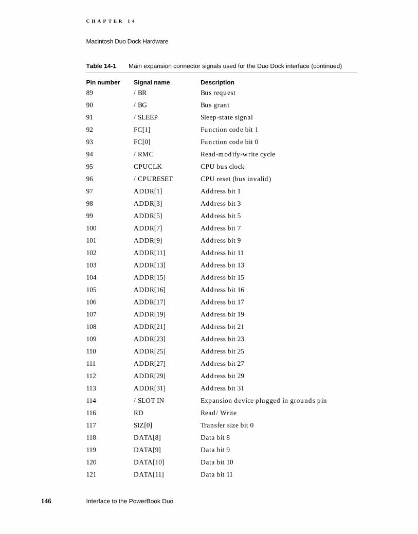
C H A P T E R 1 4
Macintosh Duo Dock Hardware
89 /BR Bus request
90 /BG Bus grant
91 /SLEEP Sleep-state signal
92 FC[1] Function code bit 1
93 FC[0] Function code bit 0
94 /RMC Read-modify-write cycle
95 CPUCLK CPU bus clock
96 /CPURESET CPU reset (bus invalid)
97 ADDR[1] Address bit 1
98 ADDR[3] Address bit 3
99 ADDR[5] Address bit 5
100 ADDR[7] Address bit 7
101 ADDR[9] Address bit 9
102 ADDR[11] Address bit 11
103 ADDR[13] Address bit 13
104 ADDR[15] Address bit 15
105 ADDR[16] Address bit 16
106 ADDR[17] Address bit 17
107 ADDR[19] Address bit 19
108 ADDR[21] Address bit 21
109 ADDR[23] Address bit 23
110 ADDR[25] Address bit 25
111 ADDR[27] Address bit 27
112 ADDR[29] Address bit 29
113 ADDR[31] Address bit 31
114 /SLOT IN Expansion device plugged in grounds pin
116 RD Read/Write
117 SIZ[0] Transfer size bit 0
118 DATA[8] Data bit 8
119 DATA[9] Data bit 9
120 DATA[10] Data bit 10
121 DATA[11] Data bit 11
Table 14-1 Main expansion connector signals used for the Duo Dock interface (continued)
Pin number Signal name Description
146 Interface to the PowerBook Duo

C H A P T E R 1 4
Macintosh Duo Dock Hardware
Duo Dock Main Logic Board 14
The logic required to implement Macintosh Duo Dock functions is housed on a single printed-circuit board. This section provides mechanical specifications for the board. Figure 14-4 shows the outline of the board with major components and dimensions.
122 +5VEXTSENSE +5 V external sense
123 DATA[12] Data bit 12
124 DATA[13] Data bit 13
125 DATA[14] Data bit 14
126 DATA[15] Data bit 15
127 DATA[16] Data bit 16
128 DATA[24] Data bit 24
129 DATA[25] Data bit 25
130 DATA[26] Data bit 26
131 DATA[27] Data bit 27
132 DATA[28] Data bit 28
133 DATA[29] Data bit 29
134 DATA[30] Data bit 30
135 DATA[31] Data bit 31
137 /SWIM CS SWIM chip select
138 /SLOT E IRQ Pseudo-NuBus expansion slot E interrupt
139 /PFW Power fail warning (shutdown bit)
140 /IO RESET Reset output to I/O systems
143 DAA CNTLF Modem DAA control
144 DAA ID IN ID input from 152-pin connector to modem card
145 /RING DET Ring detect signal from the modem DAA
146 /RB DVR Modem relay B driver
147 /RA DVR Modem relay A driver
148 EXT MIC SEL External microphone plugged in
Table 14-1 Main expansion connector signals used for the Duo Dock interface (continued)
Pin number Signal name Description
Duo Dock Main Logic Board 147

C H A P T E R 1 4
Macintosh Duo Dock Hardware
Macintosh Duo Dock design provides space for a logic board approximately 7 inches long by 7.5 inches wide. Width may be increased a further 1.5 inches if the modem adapter card is not used.
Figure 14-4 Outline of Macintosh Duo Dock logic board
SCC ports SCSI port
SCSI data connectorfor internal hard drive
Sound ports
VRAMs (video RAMs)
VRAM expansion card
Combo chip
VIDEO MUX
Speakerconnector
Floppyconnector
Motorout
Motorin
152-pin expansion connectorMotor PAL
CLUT/DAC
SCC transceivers
Power supply connector
Dec.ROM
VSC
Bustransceiver
Bustransceiver
40 MHzosc.
ADB port Video port
7.5"(190.50 mm)
7"(177.80 mm)
0.4" (10.16 mm)
0.4" (10.16 mm)
68882floating-point coprocessor
socket
(SIMM card)
Connectorfor modem
adapter
1.5MHzosc. Power
for SCSIhard drive
Eject buttonconnector
On/offbutton
Nuchip 34
A Out In
NuBusadapterconnector
0.4" (10.16 mm)
B
Modem Printer
148 Duo Dock Main Logic Board
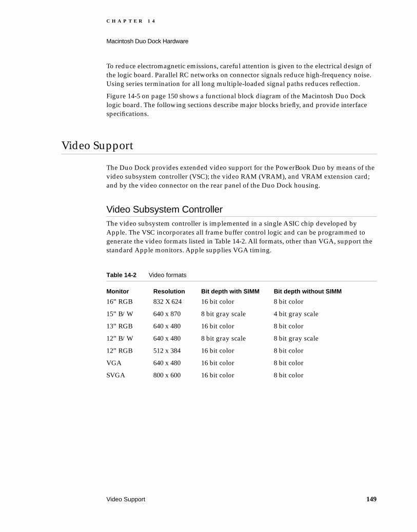
C H A P T E R 1 4
Macintosh Duo Dock Hardware
To reduce electromagnetic emissions, careful attention is given to the electrical design of the logic board. Parallel RC networks on connector signals reduce high-frequency noise. Using series termination for all long multiple-loaded signal paths reduces reflection.
Figure 14-5 on page 150 shows a functional block diagram of the Macintosh Duo Dock logic board. The following sections describe major blocks briefly, and provide interface specifications.
Video Support 14
The Duo Dock provides extended video support for the PowerBook Duo by means of the video subsystem controller (VSC); the video RAM (VRAM), and VRAM extension card; and by the video connector on the rear panel of the Duo Dock housing.
Video Subsystem Controller 14The video subsystem controller is implemented in a single ASIC chip developed by Apple. The VSC incorporates all frame buffer control logic and can be programmed to generate the video formats listed in Table 14-2. All formats, other than VGA, support the standard Apple monitors. Apple supplies VGA timing.
Table 14-2 Video formats
Monitor Resolution Bit depth with SIMM Bit depth without SIMM
16” RGB 832 X 624 16 bit color 8 bit color
15” B/W 640 x 870 8 bit gray scale 4 bit gray scale
13” RGB 640 x 480 16 bit color 8 bit color
12” B/W 640 x 480 8 bit gray scale 8 bit gray scale
12” RGB 512 x 384 16 bit color 8 bit color
VGA 640 x 480 16 bit color 8 bit color
SVGA 800 x 600 16 bit color 8 bit color
Video Support 149
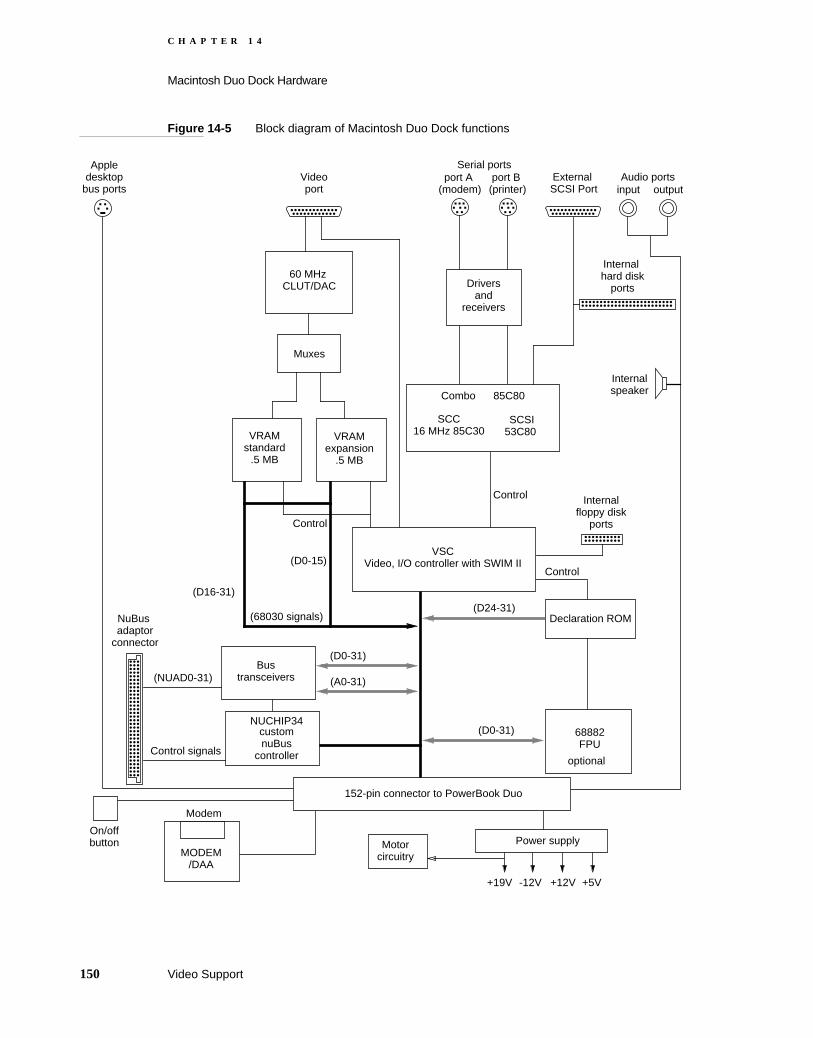
C H A P T E R 1 4
Macintosh Duo Dock Hardware
Figure 14-5 Block diagram of Macintosh Duo Dock functions
NUCHIP34customnuBus
controller
(NUAD0-31)
Control signals
NuBus adaptor
connector
Driversand
receivers
port A (modem)
port B (printer)
SCSI53C80
SCC16 MHz 85C30
Combo 85C80
Videoport
VRAMstandard
.5 MB
(D24-31)
VRAMexpansion
.5 MB
Appledesktop
bus ports
Internalfloppy disk
ports
Serial ports
Internalspeaker
60 MHz CLUT/DAC
Muxes
Internal hard disk
ports
Declaration ROM
Control
Control
(68030 signals)
Control
(D0-31)
(D0-31)
(A0-31)
(D16-31)
68882FPU
optional
Modem
MODEM/DAA
Audio portsinput output
External SCSI Port
On/offbutton Motor
circuitry
+19V +12V +5V-12V
Power supply
152-pin connector to PowerBook Duo
VSCVideo, I/O controller with SWIM II
Bustransceivers
(D0-15)
150 Video Support

C H A P T E R 1 4
Macintosh Duo Dock Hardware
Video RAM 14The video-frame buffer stores the information needed to write and refresh the video display. The basic 512 KB of video RAM (VRAM) are implemented by four 80 ns 256K x 4 VRAMs, mounted on the Duo Dock’s main logic board.
An optional 512KB of VRAM support the 16-bit video capability. Four additional 80 ns 256K x 4 video RAMs are mounted on a SIMM (single in-line memory module), which plugs into a SIMM connector on the Duo Dock’s main logic board, mounted at a 45-degree angle. Figure 14-6 shows the VRAM SIMM, and Table 14-3 lists the signal assignments for the VRAM SIMM connector.
Figure 14-6 VRAM SIMM
Table 14-3 VRAM SIMM connector signal assignments
Pin number Signal name Description
1, 29, 67, 52, 68 +5V +5 V power supply
2 DSF Data special function
3 SDB(0) Serial data input bit 0
4 SDB(1) Serial data input bit 1
5, 23, 39, 57 /DT/OE Data transfer/output enable
6 D(0) Bidirectional random data bit 0
7 D(1) Bidirectional random data bit 1
8 SDB(3) Serial data bit 3
9 SDB(2) Serial data bit 2
10 /WE Write enable
11 /RASA Row address strobe
256K x 4 video RAMs
0.75"(19.05 mm)
Pin 1 Pin 68Connector edge
4"(101.60 mm)
Video Support 151

C H A P T E R 1 4
Macintosh Duo Dock Hardware
12, 19, 20, 35, 45, 53, 54
GND Ground
13 D(3) Bidirectional random data bit 3
14 D(2) Bidirectional random data bit 2
15 VFRA(0) Multiplexed video row/column address bit 0
16 VFRA(1) Multiplexed video row/column address bit 1
17 VFRA(2) Multiplexed video row/column address bit 2
18 VFRA(3) Multiplexed video row/column address bit 3
21 SDB(4) Serial data bit 4
22 SDB(5) Serial data bit 5
24 D(4) Bidirectional random data bit 4
25 D(5) Bidirectional random data bit 5
26 SDB(7) Serial data bit 7
27 SDB(6) Serial data bit 6
28 /VFWE Write enable
30 D(7) Bidirectional random data bit 7
31 D(6) Bidirectional random data bit 6
32 /CAS(3) Column address strobe 3
33 RA(4) Multiplexed video row/column address bit 4
34 RA(5) Multiplexed video row/column address bit 5
36 SCB Shift clock B for SIMM
37 SDB(8) Serial data bit 8
38 SDB(9) Serial data bit 9
40 D(8) Bidirectional random data bit 8
41 D(9) Bidirectional random data bit 9
42 SDB(11) Serial data bit 11
43 SDB(10) Serial data bit 10
44 /WE Write enable
46 D(11) Bidirectional random data bit 11
47 D(10) Bidirectional random data bit 10
48 FRA(6) Multiplexed video row/column address bit 6
49 FRA(7) Multiplexed video row/column address bit 7
Table 14-3 VRAM SIMM connector signal assignments (continued)
Pin number Signal name Description
152 Video Support

C H A P T E R 1 4
Macintosh Duo Dock Hardware
Video Output 14A single VLSI device implements the video output circuitry. This is the color look-up table/digital-to-analog converter (CLUT/DAC).
Video Port 14The video connection is made through a standard DB-15 connector. Figure 14-7 shows the pin designations, and Table 14-4 lists the signal assignments.
Figure 14-7 Video connector pin designations
50 FRA(8) Multiplexed video row/column address bit 8
55 SDB(12) Serial data bit 12
56 SDB(13) Serial data bit 13
58 D(12) Bidirectional random data bit 12
59 D(13) Bidirectional random data bit 13
60 SDB(15) Serial data bit 15
61 SDB(14) Serial data bit 14
62 /WE Write enable
64 D(15) Bidirectional random data bit 15
65 D(14) Bidirectional random data bit 14
Table 14-4 Video connector signal assignments
Pin number Signal name Description
1 RED GND Red ground
2 RED VID Red video signal
3 /CSYNC Composite sync
4 SENSE0 Monitor sense bit 0
Table 14-3 VRAM SIMM connector signal assignments (continued)
Pin number Signal name Description
8 7 6 5 4 3 2 1
15 14 13 12 11 10 9
Video Support 153
C H A P T E R 1 4
Macintosh Duo Dock Hardware
SCSI Support 14
The Macintosh Duo Dock uses an 85C89 Combo chip to implement the SCSI channel interface.
It has an HDI-30 SCSI connector that enables hard drives, CD ROMs, and other peripheral devices to be connected to the computer. The pin designations for the SCSI connector are shown in Figure 14-8, and the signal assignments in Table 14-5.
5 GRN VID Green video signal
6 GRN GND Green ground
7 SENSE1 Monitor sense bit 1
8 nc No connection
9 BLU VID Blue video signal
10 SENSE2 Monitor sense bit 2
11 C&VSYNC GND Ground for CSYNC and VSYNC
12 /VSYNC Vertical sync
13 BLU GND Blue ground
14 HSYNC GND HSYNC ground
15 /HSYNC Horizontal sync
Table 14-4 Video connector signal assignments (continued)
Pin number Signal name Description
154 SCSI Support
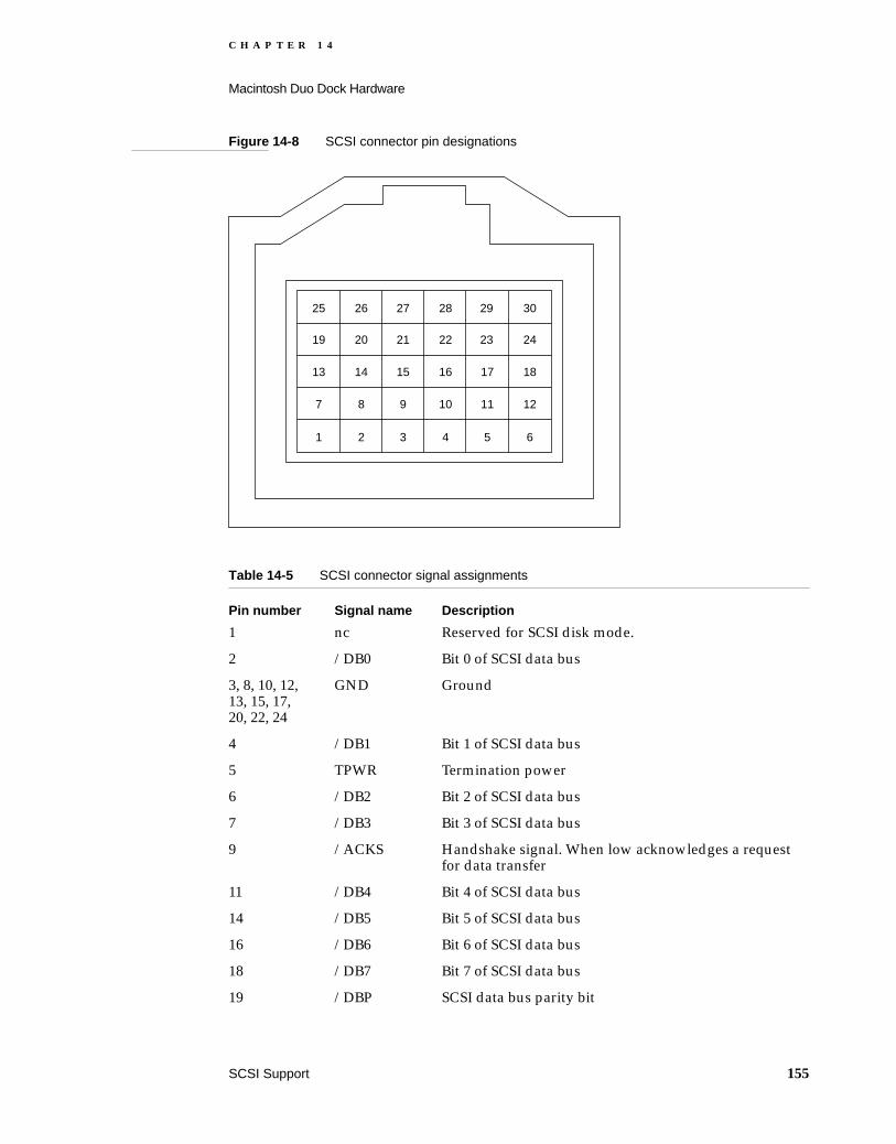
C H A P T E R 1 4
Macintosh Duo Dock Hardware
Figure 14-8 SCSI connector pin designations
Table 14-5 SCSI connector signal assignments
Pin number Signal name Description
1 nc Reserved for SCSI disk mode.
2 /DB0 Bit 0 of SCSI data bus
3, 8, 10, 12, 13, 15, 17, 20, 22, 24
GND Ground
4 /DB1 Bit 1 of SCSI data bus
5 TPWR Termination power
6 /DB2 Bit 2 of SCSI data bus
7 /DB3 Bit 3 of SCSI data bus
9 /ACKS Handshake signal. When low acknowledges a request for data transfer
11 /DB4 Bit 4 of SCSI data bus
14 /DB5 Bit 5 of SCSI data bus
16 /DB6 Bit 6 of SCSI data bus
18 /DB7 Bit 7 of SCSI data bus
19 /DBP SCSI data bus parity bit
1 2 3 4 5 6
7 8 9 10 11 12
13 14 15 16 17 18
19 20 21 22 23 24
25 26 27 28 29 30
SCSI Support 155

C H A P T E R 1 4
Macintosh Duo Dock Hardware
Serial Communication Ports 14
The 85C80 Combo chip also supports two serial communication ports used for serial input and output. The inputs and outputs are buffered and converted to RS-422 logic levels, using Apple custom driver/receiver chips.
The serial connectors are eight-pin miniature DIN connectors. Figure 14-9 shows the pin designations for the connectors, and Table 14-6 lists the signal assignments. The table indicates to which pins on the SCC Combo chip the serial port signals are connected. These ports may be used to connect a printer, or an external modem.
Figure 14-9 Serial port connector pin designations
21 /REQ Request for a data transfer
23 /BSY When active (low) indicates that the SCSI data bus is busy
25 /ATN When active (low) indicates an attention condition
26 /C/D When active (low) indicates that data is on the SCSI bus. When high, indicates that control signals are on the bus
27 /RST SCSI bus reset
28 /MSG Indicates the message phase
29 /SEL SCSI select
30 /I/O Controls the direction of data movement. When low, data is output. When high, data is input
Table 14-5 SCSI connector signal assignments (continued)
Pin number Signal name Description
1
34
8
5
7 6
2
These pins are connected to chassis ground
156 Serial Communication Ports

C H A P T E R 1 4
Macintosh Duo Dock Hardware
Apple Desktop Interface 14
A 4-pin miniature DIN (MD-4) connector connects ADB devices, such as the keyboard and mouse, to the Macintosh Duo Dock. The ADB signals pass from the MD-4 connector through EMI filters to the 152-pin main expansion connector. Figure 14-10 shows the pin designations for this connector, and Table 14-7 lists the signal assignments.
Figure 14-10 ADB connector pin designations
Table 14-6 Serial port connector signal assignments
Pin number Signal name Description
1 HSKo Handshake output. Connected to the Request to Send (RTS) pin on the Combo chip. Tristated when the Data Terminal Ready (DTR) signal is inactive.
2 HSKi Handshake input. Connected to the Transmit Receive Clock(TRXC) pin on the Combo chip.
3 /TXD Transmit data (inverted). Connected to the Transmit Data (TXD) pin on the Combo chip. Tristated when DTR is inactive.
4 SG Signal ground. Connected to logic and chassis ground.
5 /RXD Receive data (inverted). Connected to the Receive Data (RXD) pin on the Combo chip.
6 TXD Transmit data. Connected to the Transmit Data (TXD) pin on the Combo chip. Tristated when DTR is inactive.
7 GPi General purpose input. Connected to the Data Carrier Detect (DCD) pin on the Combo chip.
8 RXD+ Receive data. Connected to the Receive Data (RXD) pin on the Combo chip.
10, 11, 12 GND These pins are connected to chassis ground.
These pins are connected to chassis ground
3
2 1
4
Apple Desktop Interface 157

C H A P T E R 1 4
Macintosh Duo Dock Hardware
Sound Ports 14
Two monaural mini phone jacks provide connections for sound input and output.
Modem Adapter Card 14
When the PowerBook Duo computer is housed in the Macintosh Duo Dock, you cannot access the integral modem via the RJ-11 connector on the PowerBook Duo’s rear panel. A modem adapter card provides the connection. It plugs into the side of the Duo Dock’s main logic board, using a 10-pin header connector. The card supplies the RJ-11 hook up, which is accessed on the rear panel of the Duo Dock. The adapter card interfaces with the modem card in the PowerBook Duo computer via its 10-pin connector, printed circuit traces, and the 152-pin expansion connector. Figure 14-11 shows an outline of the adapter card. Table 14-8 lists the signal assignments for the connector. Modem card functions are described in detail in Part 1 of this publication.
Table 14-7 ADB connector signal assignments
Pin number Signal name Description
1 ADB Bidirectional data bus for input and output
2 POWER ON Key on ADB keyboard (if connected) grounds this pin to pin 4, enabling power to be turned on from the keyboard
3 +5V +5 V power
4 GND Logic ground
5, 6, 7 GND Chassis ground
158 Sound Ports
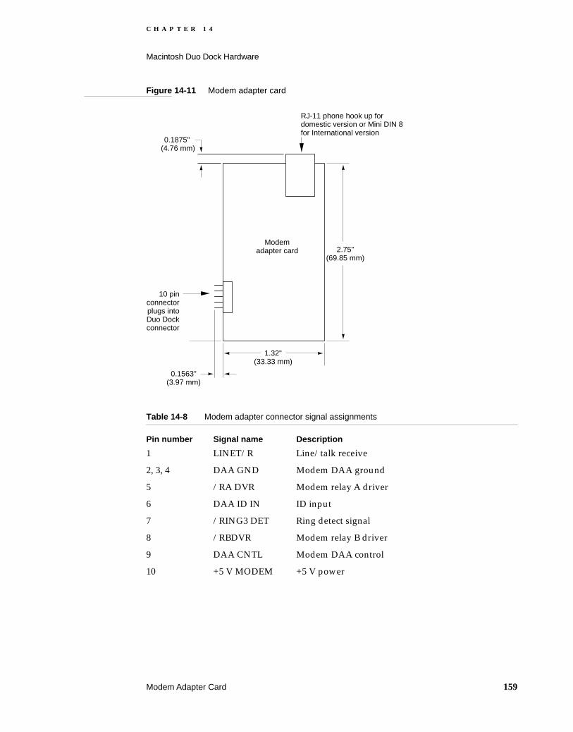
C H A P T E R 1 4
Macintosh Duo Dock Hardware
Figure 14-11 Modem adapter card
Table 14-8 Modem adapter connector signal assignments
Pin number Signal name Description
1 LINET/R Line/talk receive
2, 3, 4 DAA GND Modem DAA ground
5 /RA DVR Modem relay A driver
6 DAA ID IN ID input
7 /RING3 DET Ring detect signal
8 /RBDVR Modem relay B driver
9 DAA CNTL Modem DAA control
10 +5 V MODEM +5 V power
10 pin connector plugs into Duo Dock connector
RJ-11 phone hook up for domestic version or Mini DIN 8 for International version
0.1875" (4.76 mm)
1.32" (33.33 mm)
2.75" (69.85 mm)
0.1563" (3.97 mm)
Modem adapter card
Modem Adapter Card 159
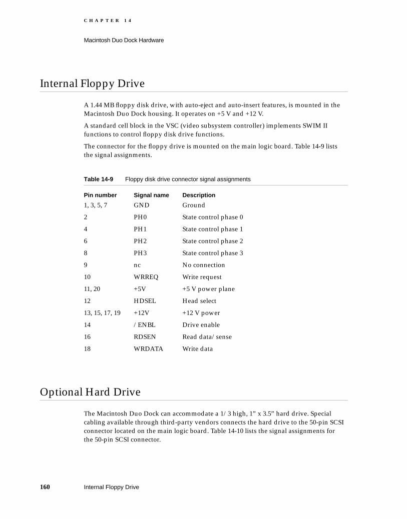
C H A P T E R 1 4
Macintosh Duo Dock Hardware
Internal Floppy Drive 14
A 1.44 MB floppy disk drive, with auto-eject and auto-insert features, is mounted in the Macintosh Duo Dock housing. It operates on +5 V and +12 V.
A standard cell block in the VSC (video subsystem controller) implements SWIM II functions to control floppy disk drive functions.
The connector for the floppy drive is mounted on the main logic board. Table 14-9 lists the signal assignments.
Optional Hard Drive 14
The Macintosh Duo Dock can accommodate a 1/3 high, 1” x 3.5” hard drive. Special cabling available through third-party vendors connects the hard drive to the 50-pin SCSI connector located on the main logic board. Table 14-10 lists the signal assignments for the 50-pin SCSI connector.
Table 14-9 Floppy disk drive connector signal assignments
Pin number Signal name Description
1, 3, 5, 7 GND Ground
2 PH0 State control phase 0
4 PH1 State control phase 1
6 PH2 State control phase 2
8 PH3 State control phase 3
9 nc No connection
10 WRREQ Write request
11, 20 +5V +5 V power plane
12 HDSEL Head select
13, 15, 17, 19 +12V +12 V power
14 /ENBL Drive enable
16 RDSEN Read data/sense
18 WRDATA Write data
160 Internal Floppy Drive

C H A P T E R 1 4
Macintosh Duo Dock Hardware
Power available for the upgrade is 700 mA, +5 V, no surge; 300 mA, +12 V, steady state; up to 1.3 A, +12 V, for a surge of eight seconds.
Table 14-10 Hard drive 50-pin SCSI connector signal assignments
Pin number Signal name Description
2 DB(0) SCSI data bit 0
4 DB(1) SCSI data bit 1
6 DB(2) SCSI data bit 2
8 DB(3) SCSI data bit 3
10 DB(4) SCSI data bit 4
12 DB(5) SCSI data bit 5
14 DB(6) SCSI data bit 6
16 DB(7) SCSI data bit 7
18 DBP SCSI parity bit
25 nc Not connected
26 TERMPWR +5 V for terminating resistors
32 /ATN Attention indicator
36 /BSY Busy
38 /ACKS Acknowledge handshake signal
40 /RST SCSI bus reset
42 /MSG Message phase
44 /SEL Select
46 /C/D Control signals or data on the SCSI bus
48 /REQ Access request
50 /I/O SCSI input/output
1, 3, 5, 7, 9,11, 13, 15, 17, 19, 20, 21, 22, 23, 24, 27, 28, 29, 30, 31, 33, 34, 35, 37, 39, 41, 42, 45, 47, 49
GND Ground
Optional Hard Drive 161
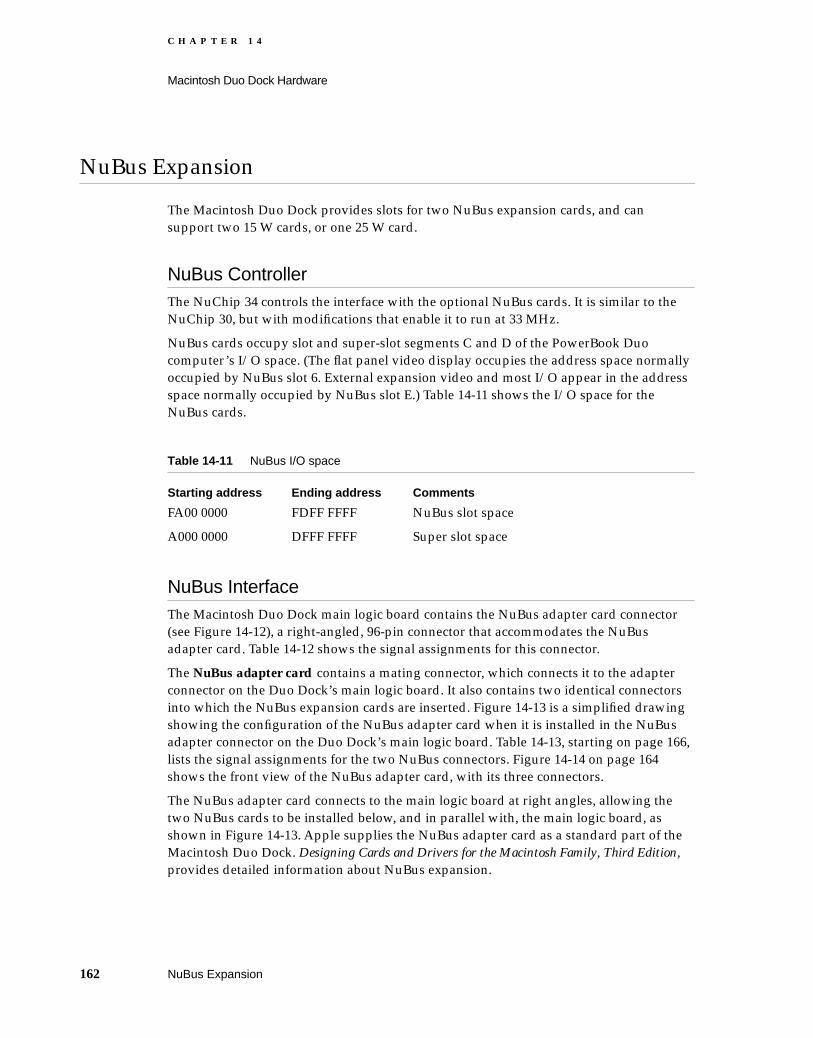
C H A P T E R 1 4
Macintosh Duo Dock Hardware
NuBus Expansion 14
The Macintosh Duo Dock provides slots for two NuBus expansion cards, and can support two 15 W cards, or one 25 W card.
NuBus Controller 14The NuChip 34 controls the interface with the optional NuBus cards. It is similar to the NuChip 30, but with modifications that enable it to run at 33 MHz.
NuBus cards occupy slot and super-slot segments C and D of the PowerBook Duo computer’s I/O space. (The flat panel video display occupies the address space normally occupied by NuBus slot 6. External expansion video and most I/O appear in the address space normally occupied by NuBus slot E.) Table 14-11 shows the I/O space for the NuBus cards.
NuBus Interface 14The Macintosh Duo Dock main logic board contains the NuBus adapter card connector (see Figure 14-12), a right-angled, 96-pin connector that accommodates the NuBus adapter card. Table 14-12 shows the signal assignments for this connector.
The NuBus adapter card contains a mating connector, which connects it to the adapter connector on the Duo Dock’s main logic board. It also contains two identical connectors into which the NuBus expansion cards are inserted. Figure 14-13 is a simplified drawing showing the configuration of the NuBus adapter card when it is installed in the NuBus adapter connector on the Duo Dock’s main logic board. Table 14-13, starting on page 166, lists the signal assignments for the two NuBus connectors. Figure 14-14 on page 164 shows the front view of the NuBus adapter card, with its three connectors.
The NuBus adapter card connects to the main logic board at right angles, allowing the two NuBus cards to be installed below, and in parallel with, the main logic board, as shown in Figure 14-13. Apple supplies the NuBus adapter card as a standard part of the Macintosh Duo Dock. Designing Cards and Drivers for the Macintosh Family, Third Edition, provides detailed information about NuBus expansion.
Table 14-11 NuBus I/O space
Starting address Ending address Comments
FA00 0000 FDFF FFFF NuBus slot space
A000 0000 DFFF FFFF Super slot space
162 NuBus Expansion

C H A P T E R 1 4
Macintosh Duo Dock Hardware
Figure 14-12 NuBus adapter connector on Macintosh Duo Dock logic board
Figure 14-13 NuBus adapter card mounting configuration
Duo Dock main logic board side view
NuBus adapter card connector mounted on Duo Dock main logic board
NuBus adapter card connector
Pin 32 Pin 1
Row ARow BRow C
NuBus card
NuBus card
Mating connector for NuBus adapter card connector
Duo Dock main logic board
NuBus adapter card
Side view of NuBus cards mounted on adapter card below Duo Dock main logic board
NuBus connectors mounted on NuBus adapter card
NuBus adapter card connector mounted on docking station main logic board
NuBus Expansion 163

C H A P T E R 1 4
Macintosh Duo Dock Hardware
Figure 14-14 Front view of NuBus adapter card showing connectors
Table 14-12 NuBus adapter card connector signal assignments
Pin number Signal name Description
A1-4 12V -12 V power supply
A5 /TM1 Transfer mode 1
A6 /AD1 Address/data 1
A7 /AD3 Address/data 3
A8 /AD5 Address/data 5
A9 /AD7 Address/data 7
A10 /AD9 Address/data 9
A11 /AD11 Address/data 11
A12 /AD13 Address/data 13
A13 /AD15 Address/data 15
A14 /AD17 Address/data 17
A15 /AD19 Address/data 19
A16 /AD21 Address/data 21
A17 /AD23 Address/data 23
Mating connector for the NuBus adapter connector mounted on Duo Dock main logic board
NuBus connectorsaccommodate theconnectors onNuBus cards
C slot
D slot
164 NuBus Expansion

C H A P T E R 1 4
Macintosh Duo Dock Hardware
A18 /AD25 Address/data 25
A19 /AD27 Address/data 27
A20 /AD29 Address/data 29
A21 /AD31 Address/data 31
A22, 23 GND Ground
A24 /ARB1 Arbitration 1
A25 /NBIRQC Interrupt request for slot C
A26, 27, 32 +12V +12 V power input
A28 /ACK Acknowledge
A29 +5V +5 V power input
A30 /RQST Request
A31 /NBIRQD Interrupt request for slot D
B1 -12V -12 V power input
B2, 3, 8-25, 30, 31 GND Ground
B4-7, 28, 29 +5V +5 V power input
B26, 27, 32 +12V +12 V power input
C1 /NUBRRST NuBus reset
C2-4, 26, 27, 29, 30 +5V +5 V power input
C5 /TM0 Transfer mode 0
C6 /AD0 Address/data 0
C7 /AD2 Address/data 2
C8 /AD4 Address/data 4
C9 /AD6 Address/data 6
C10 /AD8 Address/data 8
C11 /AD10 Address/data 10
C12 /AD12 Address/data 12
C13 /AD14 Address/data 14
C14 /AD16 Address/data 16
C15 /AD18 Address/data 18
C16 /AD20 Address/data 20
C17 /AD22 Address/data 22
C18 /AD24 Address/data 24
Table 14-12 NuBus adapter card connector signal assignments (continued)
Pin number Signal name Description
NuBus Expansion 165

C H A P T E R 1 4
Macintosh Duo Dock Hardware
C19 /AD26 Address/data 26
C20 /AD28 Address/data 28
C21 /AD30 Address/data 30
C22, 31 GND Ground
C23 /PFW Power fail warning
C24 /ARB0 Arbitration 0
C25 /ARB2 Arbitration 2
C28 /START Start
C32 /NUCLK NuBus clock
Table 14-13 NuBus adapter card connector signal assignments
Pin Signal name Description
A1 -12V -12 V power input
A2 SB0 Serial bus 0
A3 /SPV System parity
A4 /SP System parity valid
A5 /TM1 Transfer mode 1
A6 /AD1 Address/data 1
A7 /AD3 Address/data 3
A8 /AD5 Address/data 5
A9 /AD7 Address/data 7
A10 /AD9 Address/data 9
A11 /AD11 Address/data 11
A12 /AD13 Address/data 13
A13 /AD15 Address/data 15
A14 /AD17 Address/data 17
A15 /AD19 Address/data 19
A16 /AD21 Address/data 21
A17 /AD23 Address/data 23
A18 /AD25 Address/data 25
A19 /AD27 Address/data 27
Table 14-12 NuBus adapter card connector signal assignments (continued)
Pin number Signal name Description
166 NuBus Expansion

C H A P T E R 1 4
Macintosh Duo Dock Hardware
A20 /AD29 Address/data 29
A21 /AD31 Address/data 31
A22, 23 27 GND Ground
A24 /ARB1 Arbitration 1
A25 /ARB3 Arbitration 3
A26 /ID1 Slot identification 1. Not connected
A27 /ID3 Slot identification 3. Grounded
A28 /ACK Acknowledge
A29 +5V +5 V power input
A30 /RQST NuBus card request
A31 /NBIRQD Interrupt request for slot D
A32 +12V +12 V power input
B1 -12V -12 V power input
B2, 3, 8-27, 30, 31 GND Ground
B4-7, 28,29 +5V +5 V power input
B24 /NUCLK2X NuBus clock 2X
B25 STDBYPWR Standby power
B26 /CLK2XEN Clock 2X enable
B27 /NUCBUSY NuBus card busy
B32 +12V +12 V power input
C1 NUBRRST NuBus reset
C2 SB1 Serial bus 1
C3, 4, 29, 30 +5V +5 V power input
C5 /TM0 Transfer mode 0
C6 /AD0 Address/data 0
C7 /AD2 Address/data 2
C8 /AD4 Address/data 4
C9 /AD6 Address/data 6
C10 /AD8 Address/data 8
C11 /AD10 Address/data 10
C12 /AD12 Address/data 12
C13 /AD14 Address/data 14
Table 14-13 NuBus adapter card connector signal assignments (continued)
Pin Signal name Description
NuBus Expansion 167

C H A P T E R 1 4
Macintosh Duo Dock Hardware
Floating-Point Unit Interface 14
The Macintosh Duo Dock main logic board provides a PLCC socket for an optional 68882 floating-point unit. Table 14-14 lists the signal assignments for the device.
C14 /AD16 Address/data 16
C15 /AD18 Address/data 18
C16 /AD20 Address/data 20
C17 /AD22 Address/data 22
C18 /AD24 Address/data 24
C19 /AD26 Address/data 26
C20 /AD28 Address/data 28
C21 /AD30 Address/data 30
C2, 26, 27, 31 GND Ground
C23 /PFW Power fail warning
C24 /ARB0 Arbitration 0
C25 /ARB2 Arbitration 2
C26 /ID0 Slot identification 0. Grounded
C27 /ID2 Slot identification 2. Grounded
C28 /START Start
C32 /NUCLK NuBus clock
Table 14-14 FPU interface signal assignments
Pin number Signal name Description
1 D(2) Data bit 2
2 D(1) Data bit 1
3 D(0) Data bit 0
4 /SENSE Sense signal. Tied to ground
5, 6, 7, 8, 9, 12, 14,
GND Ground
19, 30, 41, 51, 63 GND Ground
Table 14-13 NuBus adapter card connector signal assignments (continued)
Pin Signal name Description
168 Floating-Point Unit Interface
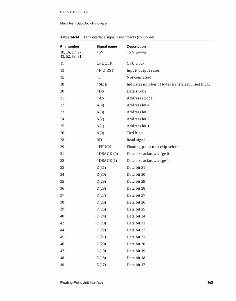
C H A P T E R 1 4
Macintosh Duo Dock Hardware
10, 16, 17, 27, 43, 52, 53, 61
+5V +5 V power
11 CPUCLK CPU clock
13 /I/O RST Input/output reset
15 nc Not connected
18 /SIZE Indicates number of bytes transferred. Tied high.
20 /DS Data strobe
21 /AS Address strobe
22 A(4) Address bit 4
23 A(3) Address bit 3
24 A(2) Address bit 2
25 A(1) Address bit 1
26 A(0) Tied high
28 RD Read signal
29 /FPUCS Floating-point unit chip select
31 /DSACK (0) Data size acknowledge 0
32 /DSACK(1) Data size acknowledge 1
33 D(31) Data bit 31
34 D(30) Data bit 30
35 D(29) Data bit 29
36 D(28) Data bit 28
37 D(27) Data bit 27
38 D(26) Data bit 26
39 D(25) Data bit 25
40 D(24) Data bit 24
42 D(23) Data bit 23
44 D(22) Data bit 22
45 D(21) Data bit 21
46 D(20) Data bit 20
47 D(19) Data bit 19
48 D(18) Data bit 18
49 D(17) Data bit 17
Table 14-14 FPU interface signal assignments (continued)
Pin number Signal name Description
Floating-Point Unit Interface 169

C H A P T E R 1 4
Macintosh Duo Dock Hardware
Power Supply 14
The Macintosh Duo Dock power supply provides the following DC voltages internally: +5 V, -12 V, +12 V, and +19 V. The power supply provides 75 watts of continuous power, and 85 watts of surge power. A microcontroller provides the logic for power on and power-down sequencing for the locked, sleep, and shut-down states of the computer. The power supply unit, positioned at the back of the Macintosh Duo Dock housing, has its own fan that draws air from inside the Macintosh Duo Dock, and forces it out through the rear vents.
The on/off power switch on the Macintosh Duo Dock rear panel resets the Power Manager on the PowerBook Duo main logic board. If the computer is off, releasing the switch turns it on. If it is on, releasing the switch turns off the computer. The Power Manager handles the sequencing to turn off the computer and Macintosh Duo Dock power supplies in the correct order. Table 14-15 summarizes DC output currents and power requirements. Table 14-16 shows DC voltage cross-regulation limits.
50 D(16) Data bit 16
54 D(15) Data bit 15
55 D(14) Data bit 14
56 D(13) Data bit 13
57 D(12) Data bit 12
58 D(11) Data bit 11
59 D(10) Data bit 10
60 D(9) Data bit 9
62 D(8) Data bit 8
64 D(7) Data bit 7
65 D(6) Data bit 6
66 D(5) Data bit 5
67 D(4) Data bit 4
68 D(3) Data bit 3
Table 14-14 FPU interface signal assignments (continued)
Pin number Signal name Description
170 Power Supply
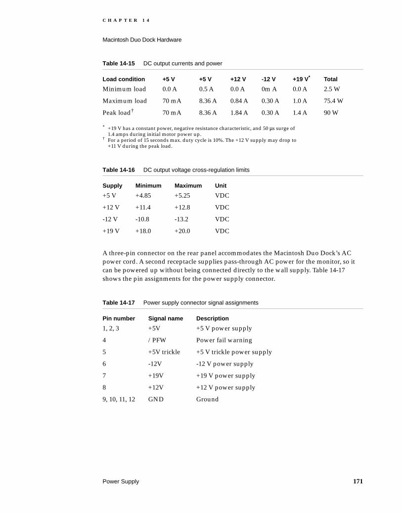
C H A P T E R 1 4
Macintosh Duo Dock Hardware
A three-pin connector on the rear panel accommodates the Macintosh Duo Dock’s AC power cord. A second receptacle supplies pass-through AC power for the monitor, so it can be powered up without being connected directly to the wall supply. Table 14-17 shows the pin assignments for the power supply connector.
* +19 V has a constant power, negative resistance characteristic, and 50 µs surge of 1.4 amps during initial motor power up.
† For a period of 15 seconds max. duty cycle is 10%. The +12 V supply may drop to +11 V during the peak load.
Table 14-15 DC output currents and power
Load condition +5 V +5 V +12 V -12 V +19 V* Total
Minimum load 0.0 A 0.5 A 0.0 A 0m A 0.0 A 2.5 W
Maximum load 70 mA 8.36 A 0.84 A 0.30 A 1.0 A 75.4 W
Peak load† 70 mA 8.36 A 1.84 A 0.30 A 1.4 A 90 W
Table 14-16 DC output voltage cross-regulation limits
Supply Minimum Maximum Unit
+5 V +4.85 +5.25 VDC
+12 V +11.4 +12.8 VDC
-12 V -10.8 -13.2 VDC
+19 V +18.0 +20.0 VDC
Table 14-17 Power supply connector signal assignments
Pin number Signal name Description
1, 2, 3 +5V +5 V power supply
4 /PFW Power fail warning
5 +5V trickle +5 V trickle power supply
6 -12V -12 V power supply
7 +19V +19 V power supply
8 +12V +12 V power supply
9, 10, 11, 12 GND Ground
Power Supply 171

C H A P T E R 1 4
Macintosh Duo Dock Hardware
Network Support 14
Connector space is allocated on the rear panel of the Macintosh Duo Dock to accommodate a future network hook-up.
172 Network Support

C H A P T E R 1 5
Figure 15-0Listing 15-0Table 15-0
Software Issues for the Duo Dock 15

C H A P T E R 1 5
Software Issues for the Duo Dock
This chapter discusses the software issues raised when docking the PowerBook Duo in the Macintosh Duo Dock. This chapter covers the following topics:
docking and undocking the PowerBook Duo: conditions and constraints
preference and information identities
multiple environments
moving from a single- to a multiple-port environment
system software modifications
declaration ROM functions
modifications to system ROM functions
Docking and Undocking the PowerBook Duo 15
The process of attaching the PowerBook Duo to a Macintosh Duo Dock is referred to as docking. Removing the computer from a Macintosh Duo Dock is called undocking.
This section describes procedures and conditions for docking and undocking, and the constraints placed on external devices, such as keyboards, floppy disk and hard disk drives.
Docking Conditions 15The PowerBook Duo exists in one of three possible states: off, operational, and asleep. Docking and undocking is perfectly safe when the computer is turned off. If the computer is operational when docked, it will shut down and restart. Behavior varies if the computer is docked when it is in the sleep state. The following section describes the conditions that occur while docking and undocking the PowerBook Duo. Table 15-1 summarizes those conditions.
Table 15-1 Conditions for docking and undocking the PowerBook Duo computer
Docking and undocking activity Duo Dock condition
PowerBook Duo on
PowerBook Duo asleep
PowerBook Duo off
Insertion Duo Dock off or on, unlocked.
CPU crash. Power turns off. Possible data loss.
CPU attempts to wake up. Goes back to sleep. PowerBook Duo is ejected.
Use external keyboard to start up.
Insertion Duo Dock off or on, locked.
Not possible.* Not possible.* Not possible.*
Running Duo Dock on, locked or unlocked.
This is normal. Not possible.† Not possible.
174 Docking and Undocking the PowerBook Duo

C H A P T E R 1 5
Software Issues for the Duo Dock
Docking Constraints 15There are several key docking constraints, for which new alert boxes have been developed.
You must close the clamshell cover of the PowerBook before docking it in the Macintosh Duo Dock. When it is closed, the PowerBook Duo goes to sleep. It is unlikely that the PowerBook Duo will be active when docked. However, if it is, the Power Manager generates an immediate shutdown. This causes the software to restart, and data may be lost, but the hardware does not latch up.
If you try to connect the PowerBook Duo to the Floppy Adapter or MiniDock while it is asleep, you will see the alert box shown in Figure 15-1. You must remove the expansion device from the PowerBook Duo, before it will wake up. You must then shut down the computer, connect the selected expansion device, and then restart the computer.
* It is not possible to insert the PowerBook Duo in the Duo Dock when the Docking station is locked.
† Sleep is not an option for the PowerBook Duo when it is docked in the Docking station.‡ The Duo Dock cannot be off if the PowerBook Duo is inserted and on.§ The Duo Dock is not on unless the PowerBook Duo is inserted and on.
Electrical eject Duo Dock off, unlocked.
Not possible.‡ OK if just inserted during sleep.
OK. Press button to eject manually.
Electrical eject Duo Dock on, unlocked.
Software shutdown Not possible.† Not possible.§
Electrical eject Duo Dock off, locked. Not possible.‡ and it’s locked.
Not possible† and it’s locked.
It’s locked.
Electrical eject Duo Dock on, locked. It’s locked. Not possible,† and it’s locked.
Not possible,§
and it’s locked.
Key hole eject Duo Dock off, unlocked.
Not possible.‡ OK if just inserted in sleep.
OK.
Key hole eject Duo Dock on, unlocked.
CPU crash. HW lines glitch. No HW damage. Power turns off.
Not possible.† Not possible.§
Key hole eject Duo Dock off, locked. Not possible,‡ and it’s locked.
Not possible, and it’s locked†.
It’s locked.
Key hole eject Duo Dock on, locked. It’s locked. Not possible,§ and it’s locked.
Not possible,§ and it’s locked.
Table 15-1 Conditions for docking and undocking the PowerBook Duo computer (continued)
Docking and undocking activity Duo Dock condition
PowerBook Duo on
PowerBook Duo asleep
PowerBook Duo off
Docking and Undocking the PowerBook Duo 175

C H A P T E R 1 5
Software Issues for the Duo Dock
Figure 15-1 Sleep alert box
Once the PowerBook Duo is docked, you must restart the computer to enable all the facilities of the computer and monitor. The computer is restarted using the power key on the external keyboard. If the machine is asleep rather than off at this stage, the PowerBook Duo is automatically ejected from the Duo Dock. The screen displays an alert message, explaining why the PowerBook Duo was ejected (see Figure 15-2). You can then open the PowerBook Duo clamshell, and deal with whatever files or applications require attention, before shutting the case and placing the computer in the Duo Dock again.
Figure 15-2 Sleep warning alert box
You may not disconnect the PowerBook Duo from the Duo Dock while it is physically locked in place. If you attempt to do this, the dialog shown in Figure 15-3 will appear on the screen.
176 Docking and Undocking the PowerBook Duo

C H A P T E R 1 5
Software Issues for the Duo Dock
Figure 15-3 Computer locked alert box
Before ejecting the PowerBook Duo, the system must be shut down. If you attempt to eject the computer while the system is running, a shutdown trap is generated, giving any applications that are running the opportunity to clean up, and allowing you to save data. To prevent the PowerBook Duo from being removed prematurely from the Duo Dock, you may lock the station. If you try to eject the PowerBook Duo while the Duo Dock is locked, the alert box shown in Figure 15-3 is displayed on the external monitor.
Preferences and Information Identities 15
When you move the PowerBook Duo computer from one Duo Dock to another, your Preferences Identity, (passwords, preferences, desktop patterns), and Information Identity (files and applications) go with the computer. To preserve these identities, the PowerBook Duo’s internal hard drive is, by default, the one from which the computer boots, both as a stand-alone computer and when docked.
By changing settings in the Start-up Control Panel, you may set up the Duo Dock’s hard drive to be the start-up hard disk. Of course, when you dock at a different station, the computer may start from the external hard disk at that station if it has the same SCSI ID as your own external hard disk. Booting from the Duo Dock’s hard disk causes you to lose Preference Identity. However, as a trade off, you can take advantage of different facilities available at the new station. Your Information Identity remains intact.
Multiple Environments 15
The PowerBook Duo is the first Macintosh designed for use both as a notebook and a desktop computer. The system software accommodates the multiple environments by providing mechanisms to determine the characteristics of the environment, and modifies internal settings to accommodate movement. Areas most affected are monitors, memory, file-server connections, and local area networks.
Preferences and Information Identities 177

C H A P T E R 1 5
Software Issues for the Duo Dock
Monitors 15When the PowerBook Duo is inserted in the Duo Dock, you must use an external monitor. (The PowerBook Duo is closed when inserted, and the flat-panel display is not accessible.) When the PowerBook Duo is used as a stand-alone computer again, the internal monitor becomes the main screen. Once you have set up the Duo Dock environment, that environment takes effect without intervention whenever the PowerBook Duo is docked.
File-Server Connections 15The PowerBook Duo institutes auto-remounting, a process in which a server is remounted when the PowerBook Duo is put to sleep or shut down, and reawakens or is rebooted attached to a network. If any files are open on a server when the PowerBook Duo tries to go to sleep, you are warned that data may be lost, and are prompted to close or save the files before allowing the computer to go to sleep. Once the files are closed, file-server connections can safely be closed, the connection information stored, and connections reestablished when the computer wakes up. You have the option to be prompted for a password before remounting, or for remounting to occur automatically. You set the option through the Remounter Control Panel.
AppleTalk 15When the PowerBook Duo is operating as a stand-alone computer, LocalTalk uses port A. When the PowerBook Duo is docked to the Duo Dock, there may be an alternate LAP card installed (Ethernet or Token Ring), in addition to the serial ports. You may select this alternate LAP in the Network cdev. When the PowerBook Duo is undocked and redocked, the system remembers which LAP was used, and automatically uses it.
Single to Multiple Ports 15
When the PowerBook Duo is used as a stand-alone computer, it has only one serial port (A). You may use this port for LocalTalk (printer hook up) or high-speed modem. When the computer is docked to the Duo Dock, this port is naturally not accessible.
The Duo Dock provides you with two serial ports (A and B). Arbitration is needed to change from a single- to a dual-port configuration. There are two scenarios.
The printer is connected to Port B using the LocalTalk, and Port A is used for a high-speed modem. The software makes the changes needed, and you do not have to go into the Chooser to specify that the printer in Port B. This is the only scenario if you wish to connect both a printer and a modem.
The printer is connected to Port A. The modem cannot be plugged into Port B, since the PowerBook Duo cannot define the functionality of the port based upon what is plugged into it.
178 Single to Multiple Ports

C H A P T E R 1 5
Software Issues for the Duo Dock
Auto-Remounting Support 15
When you choose the sleep option, the PowerBook Duo determines which servers are connected, checks open files and closes them, and saves the Volume Control Block information.
When the computer comes out of the sleep state, an item in the sleep queue initiates the mounting of servers originally connected. You can choose through a control panel whether remounting occurs, and whether a password is required.
Overview of Declaration ROM Functions 15
Certain firmware must be included on the main logic board of the Duo Dock. This firmware is stored in a ROM called the declaration ROM, and it enables the computer to distinguish between different types of expansion devices. The code required to support special services therefore resides in the Duo Dock, relieving the system ROM of the need to recognize each and every configuration
To provide the flexibility needed to support many expansion configurations, the PowerBook Duo design uses the Slot Manager model, used by NuBus cards, as the software interface. The structure of the PowerBook Duo’s declaration ROM is based on the structure of the declaration ROM designed for NuBus cards. Chapter 8 of Designing Cards and Drivers for the Macintosh, Third Edition, is crucial for an understanding of generic declaration ROM issues and ideas. Specific PowerBook Duo issues are discussed in the Appendix, “Declaration ROM Specifications.”
NoteThe declaration ROM is sometimes referred to as the configuration ROM in other Apple publications.
Overview of Modified System ROM Functions 15
This section talks about certain system ROM functions that relate specifically to the presence or absence of the Duo Dock. The system ROM checks the state of the dock at two points: when it is starting up in the normal boot process, and when it is coming out of sleep. These two processes are similar, and involve installing a handler for a particular station. The process becomes more complex if, during the sleep state, the PowerBook Duo is removed from one Duo Dock and placed in another.
Auto-Remounting Support 179

C H A P T E R 1 5
Software Issues for the Duo Dock
Start-Up Process 15Under normal conditions, when you start up the PowerBook Duo, the system ROM goes through the docking management process soon after the Slot Manager is initialized. The system ROM looks for a slot resource (sResource) on the Duo Dock’s logic board. When sResource is verified, the system ROM copies the contents of the declaration ROM’s sResource into the system heap, and replaces the Docking Dispatch trap handler with the address of the new handler. The docking handling code is physically located in a code block in the declaration ROM, and once the system ROM has installed this code block in the heap, dock handling calls can be made as required. In fact, the system ROM makes the init-selector call to allow the Duo Dock logic board to initialize itself.
Wake-Up Process 15When the computer is coming out of the sleep state, the system ROM is concerned with conditions that might have changed during sleep. The system ROM tracks the presence of a Duo Dock through the board ID (an entry in the board’s sResource, stored in the Duo Dock’s declaration ROM). By checking this entry, the system ROM can determine if conditions have remained the same, if the PowerBook Duo has been removed from the station, or moved to a new station.
If conditions are the same, the system ROM takes no action. If the PowerBook Duo has been removed or installed in a different station, the system ROM instructs the old docking handler, which still resides in the system heap, to clean up after itself. When this process is complete, the old handler is purged, and a new handler replaces its entry in the trap table. If a station has simply been removed, a default “no station” handler replaces the old entry.
From this point, the wake-up process follows the same path as the start-up process. Functionality may be limited when the computer is coming out of the sleep state. For example, video and network services are not available from the new dock, and the computer must be restarted for those functions to become active.
180 Overview of Modified System ROM Functions
A P P E N D I X
Figure A-0Listing A-0Table A-0
Declaration ROM Specifications A
This appendix describes the firmware that must be included on the logic boards of PowerBook Duo expansion devices, such as the Macintosh Duo MiniDock, and the Macintosh Duo Dock. This firmware is normally in a ROM area called the declaration ROM.
Overview A
Currently, Apple provides three expansion devices (frequently referred to in this text as devices) for the PowerBook Duo computer. They are
the Duo Dock, described in Part 3 of this developer note.
the MiniDock, described in Part 2 of this developer note.
the Floppy Adapter, described in Part 2 of this developer note.
The PowerBook Duo computer is described in Part 1 of this developer note.
The declaration ROM, located on the expansion device logic board, provides the capability to distinguish between these different types of expansion devices. It can also provide new device drivers or routines to be used by the system ROM. In this manner, the system ROM does not need to be aware of each and every type of configuration: if a special service is provided by a device, the code to perform that special service resides in the device.
In the case of a device that does not influence the functionality of the system, a declaration ROM is not required. An example of this is a device with infrared ADB: since the ADB is simply passed through to the rest of the system, no special information is required by the system. In this case, the declaration ROM is unnecessary. Another example is the Floppy Adapter, since the floppy drive is detected by the system ROM through the presence of the sense signal.
To provide flexibility in supporting many device configurations, Apple uses the Slot Manager model used by NuBus cards as the software interface. The structure of the declaration ROM for the PowerBook expansion devices is based upon the structure of the declaration (or configuration) ROM for NuBus cards. Chapter 8 of Designing Cards and Drivers for the Macintosh Family, Third Edition, is crucial for understanding generic declaration ROM issues and ideas. PowerBook specific issues are covered in this developer note.
Overview 181

A P P E N D I X
Declaration ROM Specifications
Firmware Structure A
This section provides information on the PowerBook Duo’s firmware structure.
Firmware Overview AThe firmware structure is based upon the structure of a generic NuBus card’s declaration firmware. To maintain compatibility with the Slot Manager model of dealing with NuBus cards, the declaration ROM on devices contains the following structures: a format block, a sResource directory, and a board sResource. In addition, at least one functional sResource should be included to identify the card and its function. These elements, as they relate to the PowerBook, are described in the following sections.
The Format Block AAs defined in Designing Cards and Drivers for the Macintosh Family, Third Edition, the format block consists of eight separate fields, consisting of ByteLanes, Reserved, Test Pattern, Format, RevisionLevel, CRC, Length, and DirectoryOffset. For the declaration ROM, there are no changes to the definition of these fields.
The first byte of the format block must reside at one of the four bytes at the end (or top) of the declaration ROM space, which for the PowerBook declaration ROM is between $FEFF FFFC and $FEFF FFFF, inclusive. The actual starting address depends on the value of the ByteLanes field, which indicates to the Slot Manager which byte lanes are to be used when communicating with the declaration ROM. See Designing Cards and Drivers for the Macintosh Family, Third Edition, for a list of possible ByteLane values.
The Board sResource AA board sResource (Figure A-1) is required for the firmware of every card to provide essential information to the Slot Manager about the board. The entries in a board sResource provide the computer with a card’s identification number, vendor information, board flags, and initialization code. Other entries are also available depending upon the function of the card and the desire of the manufacturer.
For all board sResources, the value of Category is $0001, and the values of cType, DrSW, and DrHW are $0000.
182 Firmware Structure

A P P E N D I X
Declaration ROM Specifications
Figure A-1 Board sResource
The PrimaryInit entry contains an offset to a PrimaryInit record. If the PrimaryInit record is not present, the computer assumes that the card initializes itself or does not require initialization. For the PowerBook declaration ROM, PrimaryInit contains interrupt handlers and video initialization code.
The sResource Directory AThe sResource directory is defined in Designing Cards and Drivers for the Macintosh Family, Third Edition. The sResource directory lists all the sResources in the card firmware and provides an offset to the beginning of each sResource. The sResource Directory is required for the Configuration ROM so the Slot Manager can recognize each sResource.
SecondaryInit is executed by the Slot Manager after all system patches have been installed. For the declaration ROM, SecondaryInit is not required.
Board sResource
sRscrType
sRscrName
BoardID
Primary init
Secondary init
Vendor info
. . .
. . .
CatBoard
TypBoard
DrSWBoard
DrHWBoard
cString
PrimaryInitRec
SecondaryInitRec
Firmware Structure 183

A P P E N D I X
Declaration ROM Specifications
Figure A-2 sResource directory
The Docking Functional sResource ACommunicating with and about the features of a PowerBook expansion device is conducted through a new A–trap call named _DockingDispatch ($AA57). Expansion devices replace the default docking handlers with their own handler. This handler is located within a special sResource on the device, known as the Docking Functional sResource.
The sRsrcType entries for this sResource, required by the Slot Manager, are defined by Macintosh DTS as shown below.
The DrvrSW and DrvrHW fields need to be assigned by Macintosh DTS on an individual basis, as shown below.
When the Docking Manager recognizes the declaration ROM on the device, it replaces its old docking handler with the handler for the currently installed device. The Docking Manager is responsible for ensuring that the correct handler is maintained if devices are
Item Duo Dock MiniDock Floppy Adapter
Category CatDock (32) CatDock (32) CatDock(32)
cType TypStation (1) TypDesk (2) TypTravel (3)
Item Duo Dock MiniDock
DrvrSw DrSWApple (1) DrSWApple (1)
DrvrHw DrHwDocking station (1)
DrHwDeskBar (1)
Format blockTop of ROM
sResource directory
ByteLanes Reserved
TestPattern
Format Revision level
CRC/checksum
Length
Directory offset
1 1
4
1 1
4
4
4
184 Firmware Structure

A P P E N D I X
Declaration ROM Specifications
changed or removed during sleep. In the case of the PowerBook Duo Floppy Adapter or in the case of no device, that is, for situations where a declaration ROM is not present, the docking handler is located in system ROM. Otherwise, the handler is located within the docking functional sResource.
Calls to the docking handler take one of two forms: status calls, to determine information about a device; and control calls, to execute certain functions pertaining to a device. Here is the C interface to the docking handler for either type of call:
long DockingDispatch (OSType selector, long params)
This is the assembly language interface:
subq.w #4,sp ; make room for result
pea selector ; docking selector
pea params ; control call parameters
_DockingDispatch ; $AA57
tst.l (sp)+ ; function result
Status calls require only one input parameter, the selector code (defined below). The result of a status call is returned as the result of the function.
Control calls also require the selector code. In addition, some control calls require an additional parameter which is passed in the params field. The result of a control call, if any, is returned as the result of the function.
A docking handler is not required to handle all status or control calls. If a handler receives a selector it doesn’t know about or care to deal with, it should simply return zero for the result, indicating that a particular function is not supported. Note that this places a restriction upon routines that ordinarily treat zero as a “no error” result: it is important for the docking handler and the calling routine to coordinate the meaning of the result parameters, so that an unsupported function is not mistakenly interpreted to be a successful result.
Table A-1 lists currently defined selectors.
Table A-1 Defined selectors
Selector Name Selector ID Type Description
dockHardwareAttr hdwr Status Hardware attributes
dockDockingAttr dock Status Docking attributes
dockLockAttr lock Status Device locking attributes
dockPowerStatus powr Status Power plane information
dockSCCReadAddr sccr Status SCC read base address (if any)
dockSCCWriteAddr sccw Status SCC write base address (if any)
dockSCCPorts scc# Status Which SCC ports are available
Firmware Structure 185
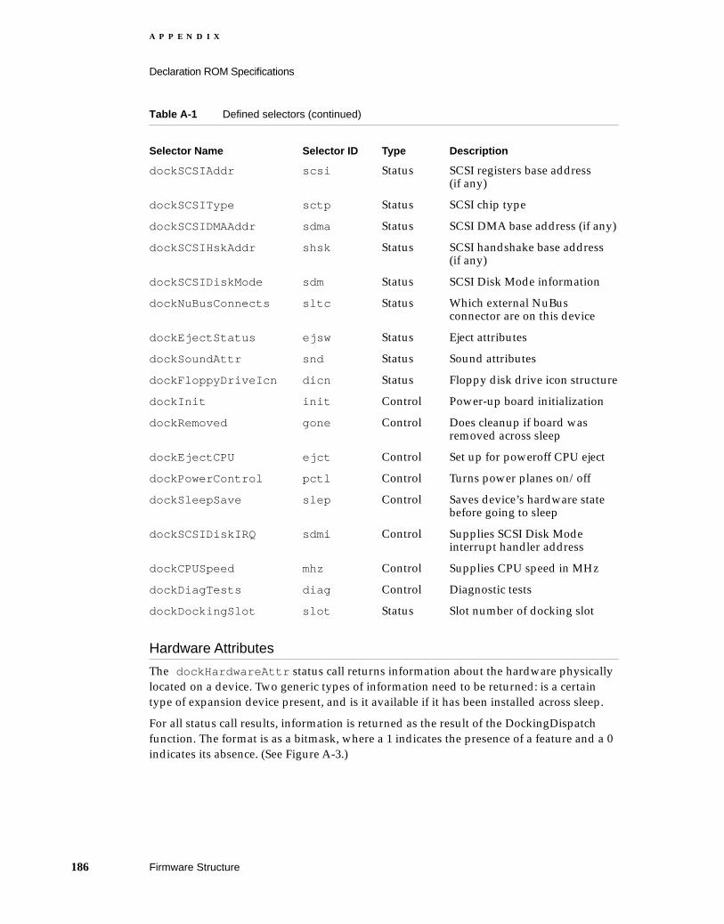
A P P E N D I X
Declaration ROM Specifications
Hardware Attributes A
The dockHardwareAttr status call returns information about the hardware physically located on a device. Two generic types of information need to be returned: is a certain type of expansion device present, and is it available if it has been installed across sleep.
For all status call results, information is returned as the result of the DockingDispatch function. The format is as a bitmask, where a 1 indicates the presence of a feature and a 0 indicates its absence. (See Figure A-3.)
dockSCSIAddr scsi Status SCSI registers base address (if any)
dockSCSIType sctp Status SCSI chip type
dockSCSIDMAAddr sdma Status SCSI DMA base address (if any)
dockSCSIHskAddr shsk Status SCSI handshake base address (if any)
dockSCSIDiskMode sdm Status SCSI Disk Mode information
dockNuBusConnects sltc Status Which external NuBus connector are on this device
dockEjectStatus ejsw Status Eject attributes
dockSoundAttr snd Status Sound attributes
dockFloppyDriveIcn dicn Status Floppy disk drive icon structure
dockInit init Control Power-up board initialization
dockRemoved gone Control Does cleanup if board was removed across sleep
dockEjectCPU ejct Control Set up for poweroff CPU eject
dockPowerControl pctl Control Turns power planes on/off
dockSleepSave slep Control Saves device’s hardware state before going to sleep
dockSCSIDiskIRQ sdmi Control Supplies SCSI Disk Mode interrupt handler address
dockCPUSpeed mhz Control Supplies CPU speed in MHz
dockDiagTests diag Control Diagnostic tests
dockDockingSlot slot Status Slot number of docking slot
Table A-1 Defined selectors (continued)
Selector Name Selector ID Type Description
186 Firmware Structure

A P P E N D I X
Declaration ROM Specifications
Figure A-3 Function result dockHardwareAttr
For the dockHardwareAttr status call, the bit fields in the result are defined in Table A-2. Bit fields not defined by Apple are available for third parties to use as they desire .
Table A-2 dockHardwareAttr bit fields.
Name Bit Description
dockHasADB 0 Has an ADB connector
dockHasSoundIn 1 Has a sound input connector
dockHasSoundOut 2 Has a sound output connector
dockHasFPU 3 FPU exists
dockHasSWIM 4 SWIM (floppy disk controller) exists
dockHasSCC 5 SCC (serial ports) exists
dockHasSCSI 6 SCSI exists
dockHasVideo 7 Video exists
dockHasNetStuff 8 Has network services (for example Ethernet) dockHasModem has modem
dockWakeADB 16 ADB available on wakeup
dockWakeSoundIn 17 Sound input available on wakeup
dockWakeSoundOut 18 Sound output available on wakeup
dockWakeFPU 19 FPU available on wakeup
dockWakeSWIM 20 SWIM available on wakeup
dockWakeSCC 21 SCC available on wakeup
dockWakeSCSI 22 SCSI available on wakeup
dockWakeNetStuff 24 Network services available on wakeup
dockWakeModem 25 Modem available on wakeup
dockWakeOther 26 Other devices available on wakeup
31 30 29 2 1 0
• • •
Function result:
Firmware Structure 187

A P P E N D I X
Declaration ROM Specifications
Docking Attributes A
The dockDockingAttr status call returns information about the docking functionality of a device. Depending upon the design of a device, certain docking features, such as going to sleep or power cycling, may not be allowed. This call is designed to allow the system to query the device to determine that information.
For all status call results, information is returned as the result of the DockingDispatch function. The format is as a bitmask, where a 1 indicates the presence of a feature and a 0 indicates its absence. (See Figure A-4.)
Figure A-4 Function result dockDockingAttr
For the dockDockingAttr status call, the bit fields in the result are defined in Table A-3. Bit fields not defined by Apple are available for third parties to use as they desire.
Locking Attributes A
The dockLockingAttr status call returns information about the locking functionality of a device. Depending upon the design of a device, mechanisms to lock the device to the CPU may be implemented. This call is designed to allow the system to query the device
Table A-3 dockDockingAttr bit fields.
Name Bit Description
dockNoSleep 0 Going to sleep is not allowed
dockNoWakeup 1 Cannot wakeup if this device was attached across sleep
dockNoPowerCycle 2 Power cycling is not allowed
dockNoLCDScreen 3 Don’t use built-in LCD screen (that is, in a docking station)
dockEnclosingBar 4 Portable is physically enclosed by the device (i.e. in a docking station)
Reserved 5 - 7 Reserved for use by Apple
31 30 29 2 1 0
• • •
Function result:
188 Firmware Structure
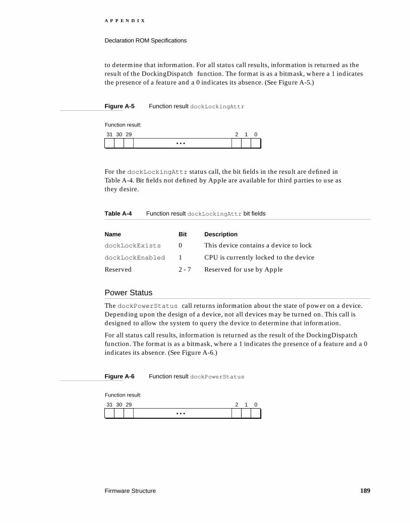
A P P E N D I X
Declaration ROM Specifications
to determine that information. For all status call results, information is returned as the result of the DockingDispatch function. The format is as a bitmask, where a 1 indicates the presence of a feature and a 0 indicates its absence. (See Figure A-5.)
Figure A-5 Function result dockLockingAttr
For the dockLockingAttr status call, the bit fields in the result are defined in Table A-4. Bit fields not defined by Apple are available for third parties to use as they desire.
Power Status A
The dockPowerStatus call returns information about the state of power on a device. Depending upon the design of a device, not all devices may be turned on. This call is designed to allow the system to query the device to determine that information.
For all status call results, information is returned as the result of the DockingDispatch function. The format is as a bitmask, where a 1 indicates the presence of a feature and a 0 indicates its absence. (See Figure A-6.)
Figure A-6 Function result dockPowerStatus
Table A-4 Function result dockLockingAttr bit fields
Name Bit Description
dockLockExists 0 This device contains a device to lock
dockLockEnabled 1 CPU is currently locked to the device
Reserved 2 - 7 Reserved for use by Apple
31 30 29 2 1 0
• • •
Function result:
31 30 29 2 1 0
• • •
Function result:
Firmware Structure 189
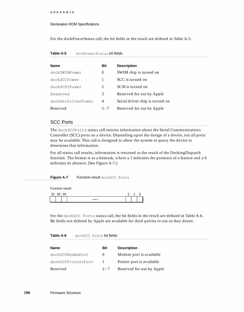
A P P E N D I X
Declaration ROM Specifications
For the dockPowerStatus call, the bit fields in the result are defined in Table A-5.
SCC Ports A
The dockSCCPorts status call returns information about the Serial Communications Controller (SCC) ports on a device. Depending upon the design of a device, not all ports may be available. This call is designed to allow the system to query the device to determine that information.
For all status call results, information is returned as the result of the DockingDispatch function. The format is as a bitmask, where a 1 indicates the presence of a feature and a 0 indicates its absence. (See Figure A-7.)
Figure A-7 Function result dockSCC Ports
For the dockSCC Ports status call, the bit fields in the result are defined in Table A-6. Bit fields not defined by Apple are available for third parties to use as they desire.
Table A-5 dockPowerStatus bit fields
Name Bit Description
dockSWIMPower 0 SWIM chip is turned on
dockSCCPower 1 SCC is turned on
dockSCSIPower 2 SCSI is turned on
Reserved 3 Reserved for use by Apple
dockSerDriverPower 4 Serial driver chip is turned on
Reserved 5 - 7 Reserved for use by Apple
Table A-6 dockSCC Ports bit fields
Name Bit Description
dockSCCModemPort 0 Modem port is available
dockSCCPrinterPort 1 Printer port is available
Reserved 2 - 7 Reserved for use by Apple
31 30 29 2 1 0
• • •
Function result:
190 Firmware Structure

A P P E N D I X
Declaration ROM Specifications
SCSI Disk Mode A
The dockSCSIDiskMode status call returns information about the presence of the SCSI disk mode cable. If a special cable is connected, the system can be placed in a special mode of operation that allows the notebook to be treated as a hard disk on another system. This call is designed to allow the system to query the device to determine that information.
For all status call results, information is returned as the result of the DockingDispatch function. The format is as a bitmask, where a 1 indicates the presence of a feature and a 0 indicates its absence. (See Figure A-8.)
Figure A-8 Function result dockSCSIDiskMode
For the dockSCSIDiskMode status call, the bit fields in the result are defined in Table A-7. Bit fields not defined by Apple are available for third parties to use as they desire.
SCSI Chip Type A
The dockSCSIType status call returns information about the type of SCSI chip installed, if any. This allows code routines to tailor their operations for a particular SCSI chip.
For all status call results, information is returned as the result of the DockingDispatch function. The format is as a bitmask, where a 1 indicates the presence of a feature and a 0 indicates its absence. (See Figure A-9.)
Figure A-9 Function result dockSCSIType
Table A-7 dockSCSIDiskMode bit fields
Name Bit Description
dockSDMExists 0 SCSI Disk Mode is supported
dockSDMCable 1 Special cable is attached
31 30 29 2 1 0
• • •
Function result:
31 30 29 2 1 0
• • •
Function result:
Firmware Structure 191

A P P E N D I X
Declaration ROM Specifications
For the dockSCSIType status call, the bit fields in the result are defined in . Bit fields not defined by Apple are available for third parties to use as they desire.
NuBus Connectors A
The dockNuBusConnects status call returns information about the external NuBus connectors on a device. Depending upon the design of a device, some NuBus slots may be available. This call is designed to allow the system to query the device to determine that information.
For all status call results, information is returned as the result of the DockingDispatch function. The format is as a bitmask, where a 1 indicates the presence of a feature and a 0 indicates its absence. (See Figure A-10.)
Figure A-10 Function result dockNuBusConnects
For the dockNuBusConnects status call, the bit fields in the result are defined in Table A-9. Bit fields not defined by Apple are available for third parties to use as they desire.
Table A-8 dockSCSIType bit fields
Name Bit Description
dock53C80 0 SCSI Chip 53C80
dock53C96 1 SCSI Chip 53C96
Reserved 2-7 Reserved for use by Apple
Table A-9 dockNuBusConnects bit fields
Name Bit Description
dockSlot9 9 Slot 9 is installed
dockSlotA 10 Slot A is installed
dockSlotB 11 Slot B is installed
dockSlotC 12 Slot C is installed
dockSlotD 13 Slot D is installed
dockSlotE 14 Slot E is installed
31 30 29 2 1 0
• • •
Function result:
192 Firmware Structure
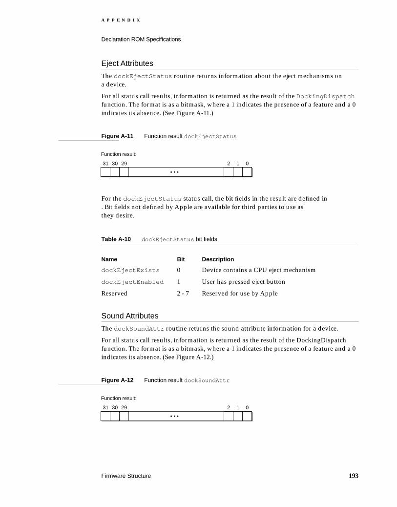
A P P E N D I X
Declaration ROM Specifications
Eject Attributes A
The dockEjectStatus routine returns information about the eject mechanisms on a device.
For all status call results, information is returned as the result of the DockingDispatch function. The format is as a bitmask, where a 1 indicates the presence of a feature and a 0 indicates its absence. (See Figure A-11.)
Figure A-11 Function result dockEjectStatus
For the dockEjectStatus status call, the bit fields in the result are defined in . Bit fields not defined by Apple are available for third parties to use as they desire.
Sound Attributes A
The dockSoundAttr routine returns the sound attribute information for a device.
For all status call results, information is returned as the result of the DockingDispatch function. The format is as a bitmask, where a 1 indicates the presence of a feature and a 0 indicates its absence. (See Figure A-12.)
Figure A-12 Function result dockSoundAttr
Table A-10 dockEjectStatus bit fields
Name Bit Description
dockEjectExists 0 Device contains a CPU eject mechanism
dockEjectEnabled 1 User has pressed eject button
Reserved 2 - 7 Reserved for use by Apple
31 30 29 2 1 0
• • •
Function result:
31 30 29 2 1 0
• • •
Function result:
Firmware Structure 193
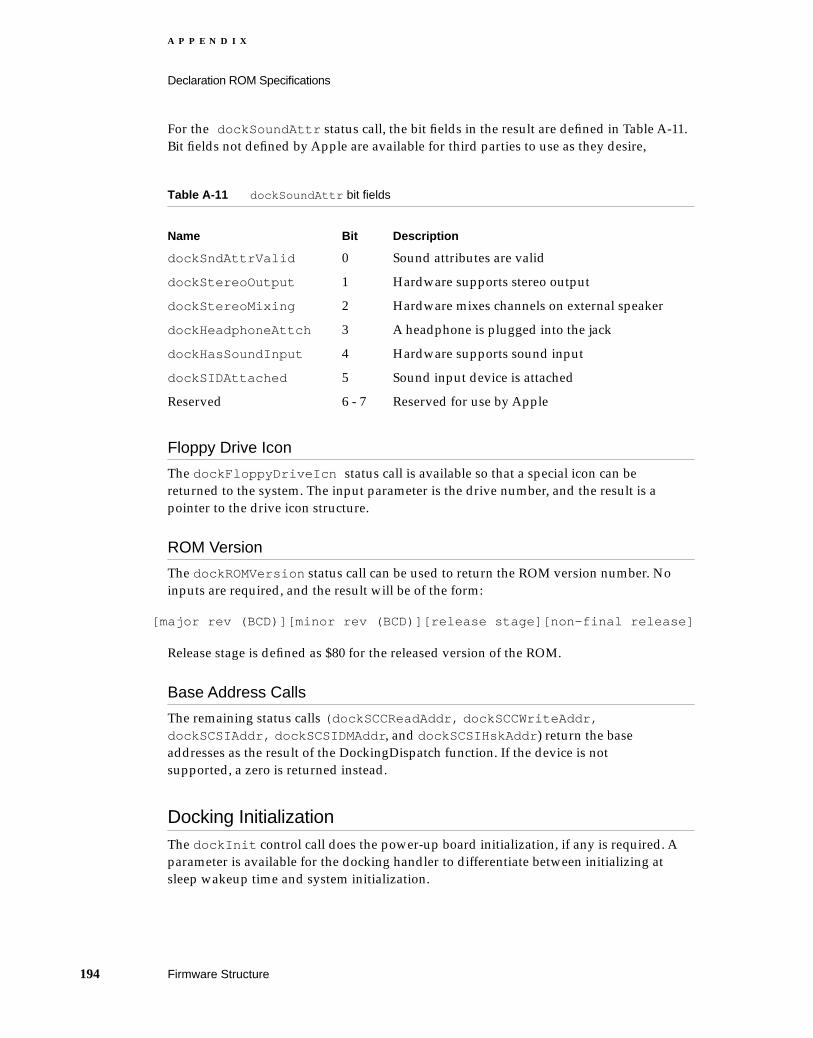
A P P E N D I X
Declaration ROM Specifications
For the dockSoundAttr status call, the bit fields in the result are defined in Table A-11. Bit fields not defined by Apple are available for third parties to use as they desire,
Floppy Drive Icon A
The dockFloppyDriveIcn status call is available so that a special icon can be returned to the system. The input parameter is the drive number, and the result is a pointer to the drive icon structure.
ROM Version A
The dockROMVersion status call can be used to return the ROM version number. No inputs are required, and the result will be of the form:
[major rev (BCD)][minor rev (BCD)][release stage][non-final release]
Release stage is defined as $80 for the released version of the ROM.
Base Address Calls A
The remaining status calls (dockSCCReadAddr, dockSCCWriteAddr, dockSCSIAddr, dockSCSIDMAddr, and dockSCSIHskAddr) return the base addresses as the result of the DockingDispatch function. If the device is not supported, a zero is returned instead.
Docking Initialization AThe dockInit control call does the power-up board initialization, if any is required. A parameter is available for the docking handler to differentiate between initializing at sleep wakeup time and system initialization.
Table A-11 dockSoundAttr bit fields
Name Bit Description
dockSndAttrValid 0 Sound attributes are valid
dockStereoOutput 1 Hardware supports stereo output
dockStereoMixing 2 Hardware mixes channels on external speaker
dockHeadphoneAttch 3 A headphone is plugged into the jack
dockHasSoundInput 4 Hardware supports sound input
dockSIDAttached 5 Sound input device is attached
Reserved 6 - 7 Reserved for use by Apple
194 Firmware Structure

A P P E N D I X
Declaration ROM Specifications
One might wish to support this particular selector if, for example, one had a hardware chip that needed to be initialized or reset in a particular manner before being used, and if that support wasn’t built into the primary or secondary init.
For all control calls, parameters are passed in the params field of the DockingDispatch call. The format is as a bitmask, where a 1 indicates the presence of a feature and a 0 indicates its absence. (See Figure A-13.)
Figure A-13 Params field dockInit
For the dockInit control call, the bit fields in the parameter are defined in . The result of the dockInit call should be zero.
Docking Cleanup A
The dockRemoved control call provides the opportunity for the docking handler to cleanup the system if a device was removed during sleep. Since hardware features have disappeared, it’s important that the system reconcile its state gracefully.
No parameter fields are defined, and the result code should be zero.
Save Sleep State A
The dockSleepSave control call is available to save the state of the device’s hardware before the system is placed into sleep. This might include the register settings of various chips on the device. The docking handler will allocate a pointer to a block containing the state of the hardware. This pointer will be returned as the result of the control call.
Restore Sleep State A
The dockWakeupRestore control call is used in conjunction with the dockSleepSave control call to restore the saved hardware state to the device after the system has come out of sleep. Registers should be restored to their saved values during this call. Through the params field of the DockingDispatch call, the docking handler will receive a pointer (originally allocated by the dockSleepSave call) to the desired hardware state.
Table A-12 dockInit fields
Name Bit Description
dockWakeupInit 0 Initializing at sleep wakeup time
31 30 29 2 1 0
• • •
Params field:
Firmware Structure 195
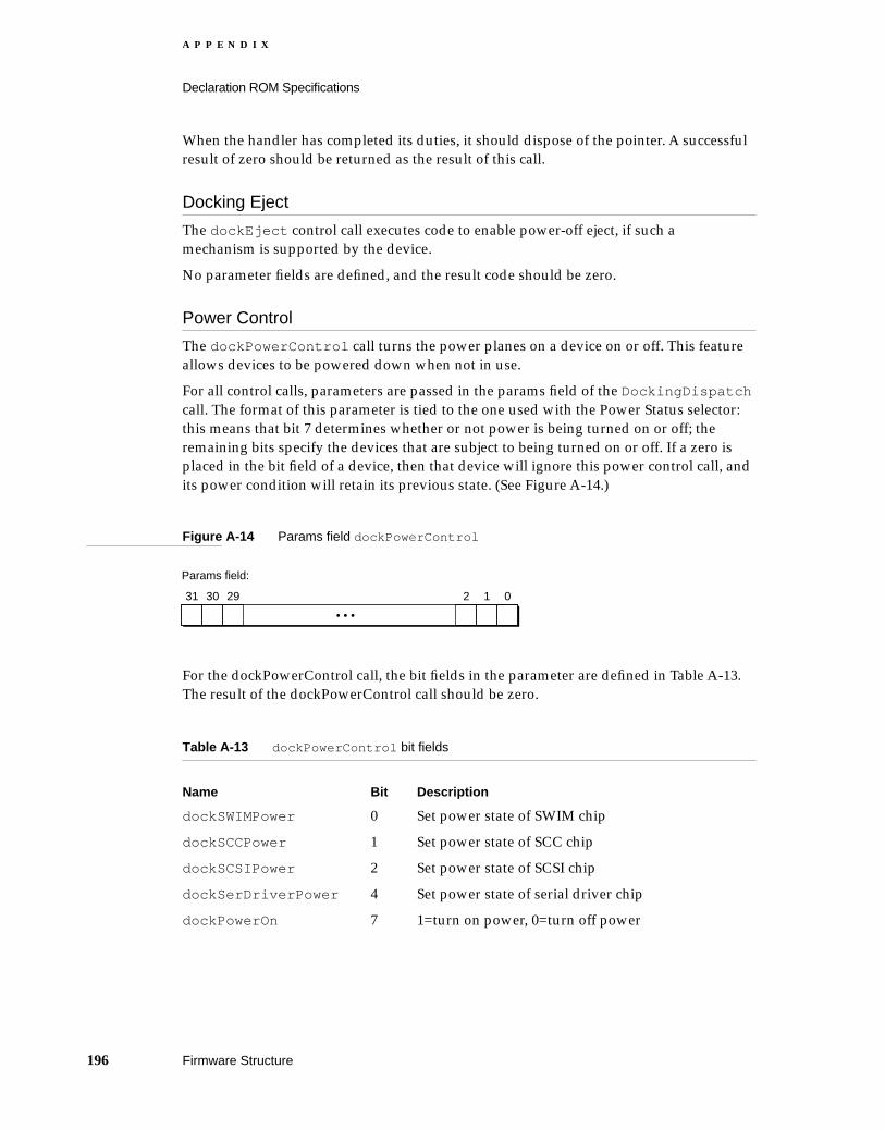
A P P E N D I X
Declaration ROM Specifications
When the handler has completed its duties, it should dispose of the pointer. A successful result of zero should be returned as the result of this call.
Docking Eject A
The dockEject control call executes code to enable power-off eject, if such a mechanism is supported by the device.
No parameter fields are defined, and the result code should be zero.
Power Control A
The dockPowerControl call turns the power planes on a device on or off. This feature allows devices to be powered down when not in use.
For all control calls, parameters are passed in the params field of the DockingDispatch call. The format of this parameter is tied to the one used with the Power Status selector: this means that bit 7 determines whether or not power is being turned on or off; the remaining bits specify the devices that are subject to being turned on or off. If a zero is placed in the bit field of a device, then that device will ignore this power control call, and its power condition will retain its previous state. (See Figure A-14.)
Figure A-14 Params field dockPowerControl
For the dockPowerControl call, the bit fields in the parameter are defined in Table A-13. The result of the dockPowerControl call should be zero.
Table A-13 dockPowerControl bit fields
Name Bit Description
dockSWIMPower 0 Set power state of SWIM chip
dockSCCPower 1 Set power state of SCC chip
dockSCSIPower 2 Set power state of SCSI chip
dockSerDriverPower 4 Set power state of serial driver chip
dockPowerOn 7 1=turn on power, 0=turn off power
31 30 29 2 1 0
• • •
Params field:
196 Firmware Structure
A P P E N D I X
Declaration ROM Specifications
SCSI Disk Mode Interrupt Handler A
The dockSDMIntHandle control call provides a method for the SCSI Disk Mode code to provide a SCSI interrupt handler to the docking manager. Typically, the parameter passed to this call is the address of a SCSI interrupt handler. If the installation of the handler is successful, a zero should be returned as the docking result.
CPU Speed A
The dockCPUSpeed control call provides a method to inform the docking handler the speed at which the CPU is operating. The parameter passed to the handler should be the CPU speed in MHz. This provides the opportunity for the docking handler to perform any hardware optimizations for a given operating frequency. The result of this call should be zero
Diagnostic Tests A
The dockDiagTests control call runs diagnostic routines to test for proper operation of the functions on a device. To prevent the diagnostic tests from lying idle in system memory when not required, the actual test code will be located in part of the board sResource on the declaration ROM. This data structure will be in the form of an SBlock and will be referred to as sDiagRec. The ID number of sDiagRec, which will be used by the Slot Manager to reference the data structure, is 85.
When the dockDiagTests control call is made, a call will be made by the docking handler to the Slot Manager to bring the diagnostic routines into system memory. Control will then be passed to the diagnostic routines, which will be responsible for conducting the appropriate tests and returning to the docking handler.
The parameter for this call will be a pointer to a diagnostic control block, containing, among other things, the list of tests to run, the number of passes, and the address of the result block. The result block provides diagnostic information about the tests which were run. The result of the DockingDispatch function call will indicate zero for an unsupported or invalid test, $8000 0000 for a successful result, or an error code defined by the test being called.
Docking Slot A
The dockDockingSlot status call is a special selector, and its support is provided by the system ROM. When this call is made, the system ROM returns the slot number of the docking slot. The declaration ROM may need to make this call if it needs to load in separate sResources that are not resident in the docking handler itself (for example, diagnostics).
Other Functional sResources AOther sResources that might be included in the PowerBook Duo declaration ROM are device drivers for video, ethernet, or non-standard serial communication. These sResources are installed and utilized exactly as if they were contained in a NuBus declaration ROM.
Firmware Structure 197

A P P E N D I X
Declaration ROM Specifications
The System ROM Process A
The system ROM needs to be concerned about checking the state of the expansion devices at two times: when it is starting up in the normal boot process, and when it is coming out of sleep. These two situations are similar, since normally they involve installing a handler for a particular device. The situation becomes more complex if during sleep one device was taken out and another put in its place. In that case, the system ROM needs to determine that things have changed and take care of things accordingly.
The Start-Up Process AThe system ROM performs its docking management when the computer is started up, soon after the Slot Manager is initialized. The first thing the system ROM does is look for a special sResource on a card. This special sResource can be identified by the presence of a CatDock category entry in the sRsrc_Type fields. When the sResource is verified, the system ROM copies the contents of the declaration ROM sResource into the system heap. At this point, the system ROM replaces the DockingDispatch trap handler with the address of the new handler.
The docking handling code is physically located in a code block (that is, an SBlock data structure), marked off by a sRsrcDock sResource ID (80), in the declaration ROM. Once the system ROM has installed this code block into the heap, dock handling calls can be made as desired. In fact, the system ROM makes the “init” selector call to allow the card the opportunity to initialize itself.
The system ROM takes care of hardware details, such as reconfiguring the base addresses (SCSI, SCC). It checks to see if the SCSI Disk Mode cable is installed, and if so, jumps off to the code to handle that situation. If not, then the normal start-up process is resumed.
The Wake-Up Process AWhen coming out of sleep, the system ROM needs to know what things have changed. Docking devices are tracked by the system ROM through the presence of the board ID, an entry in the Board sResource. The system ROM will discover that things have remained the same (the easy case), a device has been removed, or a new device has been installed.
If a device has been removed or if a new device has been installed, the system ROM tells the old docking handler (which still resides in the system heap) to clean up after itself by sending a dockRemoved selector to the docking handler. After that is completed, the old handler is purged, and a new handler replaces its entry in the trap table. In the case of a device simply being removed, a default “no device” handler replaces the old entry. If a device is swapped for a new device, then the handler for the new device acts as the replacement.
198 The System ROM Process
A P P E N D I X
Declaration ROM Specifications
From this point, the wakeup process follows the same path as the start-up process. Functionality may be limited when coming out of sleep as indicated by the hardware attribute flags. Video and network services are not available from newly added devices. The system must be restarted for those functions to come into effect.
Duo Dock versus Duo MiniDock A
Apple provides declaration ROMs for two expansion devices: the Duo Dock, and the Duo MiniDock. While the code contained in these two ROMs is similar and is even built from the same sources, the object code output is necessarily different because of the different feature sets. For example, the Duo Dock contains a power-off eject mechanism, whereas the Duo MiniDock does not. Conversely, the Duo MiniDock supports SCSI Disk Mode, whereas Duo Dock does not.
Duo Dock versus Duo MiniDock 199


Glossary
automatic gain control (AGC) Automatic volume control. A processor for holding the output of a sound system constant, despite variations in the input.
board sResource A unique sResource in an expansion device’s declaration ROM, that describes the device so that the computer can identify it.
clamshell A term used to describe the PowerBook Duo housing. A hinged case that opens to reveal keyboard and video display.
color look-up table (CLUT) A device that converts pixel data from a video frame buffer into red, green, and blue video signals.
Combo chip Controls the Serial Communica-tions Controller (SCC) interface, and the Small Computer Systems Interface (SCSI).
communication control language (CCL) A scripting language specifically designed to control a communications application, for example, an AppleLink connection (AppleLink CCL), or an AppleTalk Remove Access connection (ARA CCL).
computer operating properly (COP) feature A hardware feature of the Power Manager. Using COP, the Power Manager provides an address that must be written to in a specific way at least once every four seconds. If this write operation does not take place, the Power Manager institutes a full reset. The feature guarantees that the batteries will not be incorrectly charged for an extended period.
configuration ROM See declaration ROM.
data access arrangement (DAA) Provides the telephone line interface for the modem. In domestic applications, the DAA is an integral part of the PowerBook Duo modem card, and communicates with the telephone through an RJ-11 connector. The international version of the
modem card has a mini-DIN 8 connector, that accommodates an external DAA, which can be changed to meet telephone line requirements in different countries.
data pump driver The lowest end of the modem software. It handles control and setup, and data handling and framing.
declaration ROM A ROM located on the main logic boards of the MiniDock and the Duo Dock , or any other equivalent expansion device. It contains information about configuration, driver, and diagnostics, and it enables the Power Book Duo to recognize the expansion device to which it is attached.
digital filter audio controller (DFAC) A custom chip that performs the analog processing functions for the PowerBook Duo sound system. It comprises a sound input amplifier with AGC , a switched capacitor filer, an analog-to-digital converter, and switching amplifier circuits.
docking The process of attaching the PowerBook Duo computer to an expansion device. See also undocking.
DRAM bank See memory bank .
Duo Dock See Macintosh Duo Dock .
dynamic bus sizing The PowerBook Duo’s main processor is a 32-bit device, which means it has a 32-bit wide data bus. It supports dynamic sizing, which means it can support peripheral devices with 8-, 16-, or 32-bit data buses, without suffering from data alignment problems.
EverWatch power management feature Comprises hardware components (Power Manager, and certain MSC functions), firmware (in the form of static RAM), and supporting software. These elements conserve power when the computer is running on battery.
fast super-twist nematic (FSTN) A type of video display screen.
201

G L O S S A R Y
Floppy Adapter See PowerBook Duo Floppy Adapter.
frame buffer A buffer memory that stores all the picture elements (pixels) of a frame of video information.
general logic unit (GLU) Custom integrated circuits (ICs) used as interfaces between different logical elements of the computer.
Gestalt Manager A machine code that enables you to determine the machine on which your application is running. The code for the PowerBook Duo is 32.
gray-scale controller A custom device that controls the interface between the processor and various video components.
heap The area of memory in which space is dynamically allocated and released on demand, using the Memory Manager.
liquid crystal display (LCD) The PowerBook Duo’s integral display is an LCD which provides high-quality, black-on-white alphanumeric and graphic information.
locking mechanism A mechanical means of locking the PowerBook Duo to an expansion device. In the case of the Macintosh Duo Dock , the locking mechanism can also lock the PowerBook Duo out of the Duo Dock. See also PowerLatch Technology .
Macintosh Duo Dock A docking station that turns the PowerBook Duo into a fully functional desk-top computer. Also referred to as the Duo Dock.
Macintosh Duo MiniDock An expansion device that extends the PowerBook Duo’s I/O capabilities, giving it access to external serial ports, SCSI devices, larger monitors, floppy drives, keyboard and mouse. Also referred to as the MiniDock .
main expansion connector The 152-pin connector that interfaces the PowerBook Duo to its expansion devices, giving them direct access to the computer’s address, data, and control signals.
main processor The main processor contains an arithmetic logic unit (ALU) and system control hardware. It is the main engine of the computer. The PowerBook Duo uses an MC68030 30 MHz processor. The device is also referred to as a microprocessor.
main system controller (MSC) A custom inte-grated circuit that supports the main processor, and controls the majority of functions, including SCC and SCSI I/O. It also works with the Power Manager, to control the computer’s power saving functions. Certain MSC functions are addressed as peripheral I/O devices.
memory bank PowerBook Duo DRAM is divided into logical blocks, known as banks. Each bank contains four DRAM devices. The main logic board houses two banks, and the DRAM expansion card can accommodate four or five banks of DRAMs.
memory management unit This element of the main processor performs the memory-mapping function, using tables that contain the addresses needed to map logical memory locations to physical memory locations.
memory mapping The process of translating a logical memory address into an arbitrary physical address. It is essential in a multi-user, multitask environment, since it allows each program or task to be assigned a separate logical address space, and prevents one task from interfering with another.
memory sizing software Calculates how many banks of DRAM are in use, gives the size of each bank, and combines the segments in the address map stored in the memory management unit, so that the operating system sees contiguous blocks of memory.
microprocessor See main processor .
Mini Dock See Macintosh Duo MiniDock .
modem adapter card A small printed circuit card which plugs into the main logic boards of the Macintosh MiniDock and Macintosh Duo Dock , and provides the telephone hookup for the internal modem.
202

G L O S S A R Y
modem card A small printed circuit card which plugs into the main logic board of the PowerBook Duo , and provides modem and fax capabilities for the computer.
nap state The nap state conserves power by virtually turning off the main processor, while keeping other parts of the system, such as the hard disk, running normally.
NuBus adapter card An integral part of the Macintosh Duo Dock . Provides two slots for NuBus cards.
pipelined architecture A method of accessing the computer that allows several processes to be executed in parallel. In the case of the PowerBook Duo, the internal data and instruction caches can be accessed in parallel with bus transfers.
playthrough feature A feature of the PowerBook Duo’s sound system. It permits an external audio source to be mixed with computer-generated sound, and played out through the speaker or headphone jack.
PowerLatch Technology Provides a seamless integration between desk-top and portable computing environments. Comprises the hardware, firmware, and software support needed to attach the PowerBook Duo computer to the Macintosh Duo Dock.
Power Manager A custom microcontroller that implements the PowerBook Duo’s power management scheme.
PowerBook Duo Floppy Adapter An expansion device that provides the PowerBook Duo with access to a floppy disk drive, and to an external keyboard and mouse.
public switch telephone network (PSTN)
SCC See Serial Communication Controller .
screen dimming A control panel in the PowerBook Duo software that allows you to choose to dim the backlight on the display panel automatically.
SCSI See Small Computer System Interface.
SCSI device Any piece of equipment that can be connected to others through the SCSI bus, for example computers, hard-disk drives, and &CD ROMs.
Serial Communication Controller (SCC) ports Allow you to connect external devices, such as modems and printers, to your Apple computer.
sleep state The time when the PowerBook Duo is not in use, and most of the circuits are powered down, the screen is blank, and the hard disk is not running, is described as the sleep state. This state extends battery life by reducing power consumption almost to zero.
Small Computer System Interface (SCSI) A industry standard parallel bus that provides a consistent means of connecting computers in daisy chain fashion, and of connecting peripherals such as hard disks, and CD ROMs to computers.
SWIM II The Super Woz Integrated Machine, a custom chip used to control the floppy drive.
undocking The process of removing, or detaching, the PowerBook Duo computer from an expansion device. See also docking .
Universal ROM A single ROM used in all Macintosh computers since the Macintosh IIci. It contains the operating system for the PowerBook Duo. Minor modifications to the ROM support the PowerBook Duo’s new hardware.
versatile interface adapter (VIA) Part of the main system controller (MSC) , the VIA controls the interface between the processor and other elements in the CPU.
Video Mirroring A control panel in the PowerBook Duo’s software that allows you to display a mirror image of one screen on an external monitor.
video subsystem controller (VSC) One of the computer’s video components. An ASIC chip that incorporates frame buffer control logic, and is programmed to generate the video formats for the computer.
203

Index
Numerals
152-pin main expansion connector 393615 modem 53, 5485C80 combined SCSI and SCC controller 26
A
AC power adapter 25power supply
AC adapter 26ADB
changes to acceleration curves 80connector
pin designations 157interface 157
ADB, infrared 181ADB connector 119
Floppy Adapter 100pin designations 120signal assignments 100, 120, 158
addressing the DRAM expansion card 69address map
DRAM 19AGC 28alert boxes
computer locked 177connect 126disconnect 126sleep 176sleep warning 176
AppleTalk 178AppleTalk, port A 82arbitration, ports A and B 127, 178arbitration modes
server 55user 55
architectureexpandability 20pipelined 15software
modem 53associations 55audio ports 120automatic eject mechanism, PowerLatch
technology 139automatic gain control (AGC) 28
AutoRemounter 83AutoRemounter panel 83auto-remounting support 179
B
base address callsdockSCCReadAddr 194dockSCCWriteAddr 194dockSCSIAddr 194dockSCSIDMAAddr 194dockSCSIHskAddr 194
Batteryoperating modes 26
batterycharger 26
Battery power supply 25bit fieldsdockDockingAttr 188dockEjectStatus 193dockHardwareAttr 187dockInit 195dockLockingAttr 189dockNuBusConnects 192dockPowerControl 196dockPowerStatus 190dockSCCPorts 190dockSCSIDiskMode 191dockSCSIType 192dockSoundAttr 194
board ID 129, 180board sResource 183
C
clamshell housing 74client arbitration 55color look up table/digital-to-analog converter (CLUT/
DAC) 114, 153Combo chip 118combo chip 26
powerdrain 27
communicating with the modem 55communication
205
I N D E X
fax link 11modem link 11SCC interface 10SCSI interface 10
communications features 48communications toolbox 53compatibility, modem 54compression protocols 57computer operating properly (COP) feature 24configuration ROM 20, 81, 120connect alert box 126connection tool, modem 53connectors
ADB 100, 119DRAM expansion card 69Floppy Adapter 96floppy disk drive 101main expansion 39, 144MiniDock's main expansion connector 106modem card 58NuBus adapter card 164power 44PowerBook Duo rear panelDuo connectors 38power supply 171SCSI 117serial port 43, 119video 114
Connect to Disks By feature 84control
interrupts 21timing 21
control and processing 7control calls 185dockCPUSpeed 197dockDiagTests 197dockEject 196dockInit 194dockRemoved 195dockSDMIntHandler 197dockSleepSave 195dockWakeupRestore 196
control panelmodem 53
control panel package 84control panels
display 83PowerBook Duo 81, 82start up 126, 177
conventions used in book xviiCPU ROM, support for PowerBook Duo 80CPU speed 197current drain, hard disk 34
D
DAA 49, 52data access arrangement 49, 52data compression 11
modem 57data pump driver 84data server 55data user 55data-user associations, ring messages 56declaration ROM 20, 81, 120, 128, 138, 179declaration ROM specifications 181–199defined selectors 185design architecture 7, ??–12design specifications, DRAM expansion card 66desk-top computer 134diagnostic tests 197dialog box, options 82digital filter audio chip (DFAC) 10digital filter audio component (DFAC) 28disconnect alert box 126display control panel 83DMA, sound 21dockCPUSpeed 197dockDiagTests 197dockDockingAttr 188dockEject 196dockEjectStatus 193dockEjectStatus 193dockFloppyDriveIcon 194dockHardwareAttr 186, 187docking attributes 188docking cleanup 195docking conditions 124, 125, 174docking constraints 106, 124–??, 139, 175DockingDispatch trap 184Docking Dispatch trap handler 129, 180docking eject 196docking functional sResource 184docking handler 129, 180docking handler calls
control 185status 185
docking initialization 194docking the PowerBook Duo 124docking validation mechanism 125dockInit 194dockLockingAttr 189dockNuBusConnects 192dockPowerControl 196dockPowerStatus 189, 190dockRemoved 195dockROMVersion 194dockSCCPorts 190dockSCSIDiskMode 191
206

I N D E X
dockSCSIType 191, 192dockSDMIntHandle 197dockSleepSave 195dockSoundAttr 193, 194dockWakeupRestore 196DRAM 19
address map 19expansion card 10
DRAM components 66, 68DRAM expansion 19DRAM expansion card 19, 66, 69
addressing 69chip configuration 68connector 69current 71design specifications 66interface 69memory banks 66, 69outline 67power draw 71signal assignments 69specifications 72
Duo Dockautomatic eject mechanism 139DC output voltage cross-regulation limits 171docking constraints 139features 135housing 139, 140, 141, 142main logic board 148manual eject mechanism 139output currents 171power 171power supply 170software issues 174–180
Duo Dock hardware 138–171Duo Dock main expansion connector 144Duo Dock versus MiniDock 199dynamic bus sizing 15dynamic random access memory 19
E
eject attributes 193electrical considerations
Floppy Adapter 93MiniDock 93
electromagnetic emissions (EMI) 93, 149error correction 11error correction, modem 57error detection 11EverWatch power management feature 22expansion features 7
F
fax capabilities 48–64FAX Extension Driver 54fax link 11FAX Monitor 54FAX Monitor application 58fax receive capabilities 57fax send capabilities 57FAX sender 54fax server 55fax specifications 63fax support, software 84fax terminal software 53features
Duo Dock 135expansion 7Floppy Adapter 90, 91MiniDock 90, 91modem 54PowerBookDuo 6video 113
file server connections 127, 178firmware structure, overview 182flat-panel video display 27floating-point unit 168floating-point unit, interface 168floating-point unit support 7Floppy Adapter 90–93, 181
ADB connector 100connector 96electrical considerations 93features 90, 91hardware 96–102housing 97main logic board 99power budget 92power supply 102thermal considerations 93
Floppy Adapter connector, signal assignments 98floppy disk drive 160
connector 101floppy-disk drive
interface 116floppy disk drive connector
pin designations 101signal assignments 102, 160
floppy disk drive support 101, 115floppy-disk drive support 101floppy drive icon 194format block
182ByteLanes 182CRC 182Format 182
207

I N D E X
Length 182Reserved 182RevisionLevel 182TestPattern 182
FPU interfacesignal assignments 168
FSTN panels 27function resultsdockDockingAttr 188dockEjectStatus 193dockHardwareAttr 187dockLockingAttr 189dockNuBusConnects 192dockPowerStatus 189dockSCCPorts 190dockSCSIDiskMode 191dockSCSIType 191dockSoundAttr 193
G
Gestalt Manager 6gray-scale controller (GSC) 10, 27
H
hard disk 30–35, 161bracket 32current drain 34housing 30, 31interface 34internal 30operating modes
power off 33standby 33start-up 33
power consumption 34power requirements 33SCSI connector 35SCSI connector signal assignments 35termination 35
hard disk 50-pin SCSI connectorsignal assignments 161
hardware attributes 186hardware interface
modem card 59modem card and Duo Dock 60modem card and MiniDock 60modem card and PowerBook Duo 59
heat dissipation 93high-speed modem connections 127
housingDuo Dock 139, 140, 141, 142Floppy Adapter 97hard disk 30, 31MiniDock 105PowerBook Duo 75, 76
human interface 11keyboard 11microphone 12speaker 12trackball 11video display panel 11
I
information identityapplications 126files 126
infrared ADB 181installation, modem 57integrated VIAs 20interface
ADB 157DRAM expansion card 69floating-point unit 168Floppy Adapter with PowerBook Duo 97floppy-disk drive 116hard disk 34MiniDock with PowerBook Duo 106modem card with Duo Dock 62modem card with MiniDock 61modem card with PowerBook Duo 60modem power control 62NuBus 162PowerBook Duo 38SCC 118SCSI 154telephone line electrical 63
internal floppy drive 160internal hard disk 30I/O space, map 18
K
keyboard 11, 77
L
LCD display 11, 74
208

I N D E X
local area network (LAN) 11LocalTalk 82, 127locking attributes 189locking mechanism 139
M
machine identification 6Macintosh Duo Dock 134–135Macintosh Duo MiniDock 90–93main expansion connector 12, 39
MiniDock 106signal assignments 39, 107
main logic boardDuo Dock 148Floppy Adapter 99MiniDock 110, 112PowerBook Duo 14
main processor 15main system controller (MSC) 9, 20
power control 22, 24, 25sound control 28
manual eject mechanism, Duo Dock 139map
I/O space 18pseudo NuBus expansion space 18video buffer 18
MC68020 microprocessor 7MC68030 microprocessor 7, 15mechanical specifications, modem 48memory 10
access 21banks 19control 21DRAM 19DRAM expansion 19
memory management unit 16, 19memory mapping 16memory sizing 19microphone 12MiniDock
electrical considerations 93features 90, 91, 104logic board with components 112logic board with dimensions 113main logic board 110, 112power budget 92power sources 121thermal considerations 93
MiniDock hardware 104–122MMU 16, 19MNP II-V networking protocol 57modem
control panel 53data compression 57domestic 48error correction 57features 54installation 57mechanical specifications 48protocols 57software architecture 53
modem adapter card 122, 158, 159signal assignments 122
modem adapter connectorsignal assignments 159
modem arbitrationassociations 55client arbitration 55
modem capabilities 48–64modem card 48, 158
connector 58signal assignments 58
domestic 11electrical interface 58hardware interface 59international 11outline domestic version 49outline international version 50power requirements 58
modem card functionsdomestic and international 52
modem compatibility 54modem Control Panel 57modem CTB connection tool 57modem data pump 49modem features
arbitration 55communicating with the modem 55
modem hardware 48modem implementation for different markets 49modem international 48modem link 11modem operation
asynchronous data 11full duplex 11
modem power control interface 62modem ring messages 56modems
telephone line interface 52modem software 49modem specifications 63modem transmission protocols 55monitors 127, 178MSC 21multiple environments
AppleTalk 177file-server connections 127, 177
209
I N D E X
monitors 127, 177using the PowerBook Duo in 127, 177
N
network sensing code 84Non-data-user associations, ring messages 56NuBus
adapter card 162adapter card connector 162, 164adapter card mounting configuration 163cards 162expansion 162interface 162
NuBus adapter card connector, signal assignments 164NuBus connectors 192NuBus declaration ROM, comparison with Duo Dock's
declaration ROM 179, 181
O
optional hard disk 161options dialog box 82other sResources 197output voltage cross-regulation limits 171
P
params fieldsdockInit 195dockPowerControl 196
physical address space 17pin designations
ADB connector 120, 157floppy disk drive connector 101SCSI connector 117, 155serial port connector 119, 156video connector 114, 153
pipelined architecture 15playthrough feature 28port A, AppleTalk 82ports A and B, arbitration 127PowerBook Duo
features 6housing 74, 75, 76interface 38I/O interfaces 38–45keyboard 77main logic board 14
mechanical features 74–78physical address space 17power states 24
nap 24shutdown 25sleep 25
rear panel 38software 80–85trackball 78video display panel 74
PowerBookDuohousing 5software features 85
PowerBook Duo control panel 81, 82PowerBook Duo introduction 4–??PowerBook Duo main logic board 14–28
block diagram 14outline 15
power budgetFloppy Adapter 92MiniDock 92
power connector 44power connector signal assignments 44power consumption
hard disk 34power control 196power draw, DRAM expansion card 71PowerLatch technology 143power management
operating modes 22Power Manager 10
Power Manager 10, 20, 22, 170built-in security features 24COP feature 24sound control 28
power requirementshard disk 33, 161modem card 58
power sources, MiniDock 121power status 189power supply
AC adapter 25battery 25Duo Dock 170, 171Floppy Adapter 102ventilation 170
power supply connector, signal assignments 171preferences identity
applications 177desktop patterns 126, 177files 177passwords 126, 177preferences 126, 177
PrimaryInit 183processing and control 7
210

I N D E X
protocolscompression 57MNP II-V 57modem 57modem transmission 55
pseudo NuBus expansion spacemap 18
public switch telephone network (PSTN) 11, 48
R
RAM, video 114rear panel, PowerBook Duo 38receive capabilities, fax 57reference material xviiiregisters
sound clock rate 21sound record/play 21sound volume 21
related documentation xviiirestore sleep state 196ring messages 56
data-user associations 56non-data-user associations 56
ROMconfiguration 20, 81, 120declaration 20, 81, 120, 128, 138docking calls on 20system 19, 128, 179
process 198universal 80
ROM version 194routinesdockEjectStatus 193dockSoundAttr 193
S
save sleep state 195SCC Combo chip 27SCC controller 118SCC interface 10, 118SCC ports 190screen dimming 83scripting mechanism 55SCSI
controller 154interface 154manager 81
SCSI bus 26SCSI chip type 191
SCSI connector 117hard disk 35pin designations 117, 155signal assignments 117, 155
SCSI connector signal assignments 35SCSI controller 117SCSI device support 117SCSI disk mode 81, 191SCSI disk mode interrupt handler 197SCSI ID 177SCSI interface 10, 117selectors 185send capabilities, fax 57serial I/O 118serial port connector 43, 119
pin designations 119, 156signal assignments 119, 157
serial port connector, signal assignments 44serial ports 156server applications 55server mode 55signal assignments
ADB connector 100, 120, 158DRAM expansion card connector 69Duo Dock main expansion connector 144Floppy Adapter connector 98floppy disk drive connector 102, 160FPU interface 168hard drive 50-pin SCSI connector 161main expansion connector 39MiniDock subset of signals for the main expansion
connector 107modem adapter card 122modem adapter connector 159modem card connector 58NuBus adapter card connector 164power connector 44power supply connector 171SCSI connector 117, 155serial port connector 119, 157serial port connectors 44video connector 114, 153VRAM SIMM connector 151
SIMM 151single to multiple ports, changing from 127, 178Slot Manager 128, 129, 179, 180, 181, 182software
fax terminal 53features 85memory sizing 19support for fax 84
software architecture, modem 53software issues
Duo Dock 174–180sound
211
I N D E X
DMA 21playthrough feature 28
sound attributes 193sound buffer 28sound clock rate register 21sound components 28
built-in speaker 28external headphone jack 28microphone input jack 28
sound FIFO 21sound ports 158sound record/play register 21sound system 10sound volume register 21speaker 12specifications
DRAM expansion card 72fax 63modem 63
sResource 129, 180, 183, 184board 182directory 183
sResource directory 184sResources, other 197start-up control panel 126, 177start-up process 129, 180, 198status calls 185dockDockingAttr 188dockFloppyDriveIcon 194dockHardwareAttr 186dockLockingAttr 189dockNuBusConnects 192dockPowerStatus 189dockROMVersion 194dockSCCPorts 190dockSCCReadAddr 194dockSCCWriteAddr 194dockSCSIAddr 194dockSCSIDiskMode 191dockSCSIDMAAddr 194dockSCSIHskAddr 194dockSCSIType 191
storage capacity 10super twist nematic mode 27SWIM II 101, 114, 160SWIM II, power drain 27SWIM II controller 115System Extensions folder 57system ROM 19, 128, 180
modified functions 128system ROM process 198
T
target market 4telephone line electrical interface 63telephone line interface
modems 52termination, hard disk 35thermal considerations
Floppy Adapter 93MiniDock 93
toolbox 19trackball 78trackball assembly 11, 78
U
undocking the PowerBook Duo 124Universal ROM 80user mode 55
V
ventilation for power supply 170venting 93versatile interface adapter (VIA) 20video
buffer 151connector 114controller 114display panel 27driver, gray-scale 80features 113formats 114, 149interface 114output 114, 153port 153RAM 27, 114subsystem controller (VSC) 149system 27VRAM expansion 151
video buffer map 18video connector
pin designations 114, 153signal assignments 114, 153
video display panel 11, 74video mirroring 83video RAM 151video subsystem controller (VSC) 114, 160visual cues xviiVRAM 114, 151VRAM expansion 151
212

I N D E X
VRAM SIMM 151VRAM SIMM connector, signal assignments 151
W
wake-up process 198wake-up process, sResource 129
213

T H E A P P L E P U B L I S H I N G S Y S T E M
Draft. Preliminary, Confidential. 1995 Apple Computer, Inc. 4/4/95
This Apple manual was written, edited, and composed on a desktop publishing system using Apple Macintosh computers and FrameMaker software. Proof pages were created on an Apple LaserWriter IINTX printer. Final pages were created on the Varityper VT600 imagesetter. Line art was created using Adobe Illustrator. PostScript , the page-description language for the LaserWriter, was developed by Adobe Systems Incorporated.
Text type is Palatino and display type is Helvetica . Bullets are ITC Zapf Dingbats . Some elements, such as program listings, are set in Apple Courier.
WRITERJoyce D. Mann
DEVELOPMENTAL EDITORWendy Krafft
ART DIRECTIONSandee Karr
ILLUSTRATORSB. Carey, S. Karr, D. Olmos
PRODUCTION EDITORRex Wolf
Special thanks to Rolly Reed, Mary Johnson, Mike Johnson, Ruth Hennigar, Mark Siebert, Mark Baumwell, Markus Wellgren, David Rothschild, and Todd Kessler


