40
SURGICAL TECHNIQUE For EXPEDIUM ® 5.5 Spine System POWERED INSTRUMENTS This publication is not intended for distribution in the USA.

SURGICAL TECHNIQUE
For EXPEDIUM® 5.5 Spine System
POWERED INSTRUMENTS
This publication is not intended for distribution in the USA.


Surgical Technique Powered Instruments for EXPEDIUM 5.5 Spine System DePuy Synthes 1
FEATURES AND BENEFITS 2
PRODUCT OVERVIEW Power Tools Colibri II 4
INDICATIONS 5
SET CONTENT 6
PRE-OPERATIVE PREPARATIONS 8
SCREW BED PREPARATION Cannulation 13
Tapping 16
SCREW DELIVERY 19
Poly Driver Assembly (Polyaxial or Uniplanar Screws) 20
Poly Driver Assembly (Extended Tab Screws) 21
Loading Polyaxial, Uniplanar or Extended Tab Screws 22
Delivering a Polyaxial Screw 24
Loading a Monoaxial Screw 26
Delivering a Monoaxial Screw 27
MANUAL OPERATION 29
PROCESSING, REPROCESSING, CARE AND MAINTENANCE 30
PRODUCT CATALOG 31
TABLE OF CONTENTS
Image intensifier control

2 DePuy Synthes Powered Instruments for EXPEDIUM 5.5 Spine System Surgical Technique
EXPEDIUM System PedigreePowered Instruments for the EXPEDIUM System build upon more than ten years of clinical experience with the comprehensive EXPEDIUM 5.5 System, delivering refined instrumentation, which enables surgeons to unlock the full potential of the EXPEDIUM Platform.
Ergonomics and HealthInstrument length is designed to improve surgeon ergonomics and to provide a more comfortable shoulder and torso positioning during the procedure. Additionally, the powered handpiece reduces the number of repetitive motions that can lead to surgeon fatigue or overuse injuries1.
Speed and EfficiencyThe application of Powered Instruments offers potential timesaving for each screw implant. The greatest cumu lative benefit is expected during deformity procedures.
AccuracyThe power handpiece is designed to facilitate steadier hand positioning during pedicle preparation and screw delivery, potentially reducing the off-axis motion associated with manual pedicle preparation and screw delivery.
1 Auerbach et. Al. “Musculoskeletal Disorders Among Spine Surgeons”, Spine Vol. 36, No. 26, pp E1715-E1721, 2011.
The Powered Instruments for EXPEDIUM® Spine System enable powered drilling, tapping, and screw delivery with a cordless handpiece, Quick Coupling attachment, and optimized instrumentation.
FEATURES AND BENEFITS

Surgical Technique Powered Instruments for EXPEDIUM 5.5 Spine System DePuy Synthes 1
BiomechanicsThe Powered Instruments for the EXPEDIUM 5.5 Spine System were developed in close collaboration with deformity surgeons having ergonomics in mind. Through optimization of instrument length and geometry, shoulder, elbow, and trunk positioning is improved when compared to manual instrumentation.
During pedicle preparation and screw delivery, Powered Instrumentation allows the surgeon to maintain a low shoulder position, an elbow position close to the torso, and decreases the amount of lateral bending often seen when using manual instrumentation. Maintaining alignment of the torso while minimizing the extension of the upper extremities provides an opportunity to reduce muscle recruitment and surgeon fatigue.
Similarly, using Powered Instruments reduces the number of repetitive motions required during spine surgery, reducing energy expenditure and decreasing the potential for musculoskeletal disorders associated with overuse1.
Comparison of surgeon posture using manual and Powered Instruments:
1 Auerbach et. Al. “Musculoskeletal Disorders Among Spine Surgeons”, Spine Vol. 36, No. 26, pp E1715-E1721, 2011.
2 Shown: EXPEDIUM 5.5 System Quick Connect Polyaxial Driver 279712400 with Elliptical Handle 279702140 (not included in set Powered Instruments for EXPEDIUM 5.5 Spine System).
Comparison of shoulder height and elbow position (left: manual2, right: Powered Instruments).
Comparison of spine lateral bend and elbow lift (left: manual², right: Powered Instruments).

LI-ION
4 DePuy Synthes Powered Instruments for EXPEDIUM 5.5 Spine System Surgical Technique
Highly Controllable Power Handpiece
Powerful handpiece (85 Watts) with highly durable motor
Simple mode selection from forward to reverse and oscillation
14.4 V environment friendly* Li-Ion battery offering high battery capacity
Attachment provides speed and torque suitable for pedicle preparation and screw delivery
Push release Quick Coupling for fast instrument exchange
Standing battery casing for greater convenience
Coupling for quick and secure attachment exchange
Dual trigger for easy speed regulation and directional control
* As per Battery Directive 2006/66/EC
POWER TOOLS COLIBRI II
PRODUCT OVERVIEW

Surgical Technique Powered Instruments for EXPEDIUM 5.5 Spine System DePuy Synthes 5
Indications for Powered Instruments for EXPEDIUM 5.5 Spine System
The EXPEDIUM Spine System is intended to provide immobilisation and stabilisation of spinal segments in skeletally mature patients as an adjunct to fusion in the treatment of acute and chronic instabilities or de-formities of the thoracic, lumbar and sacral spine.
The EXPEDIUM Spine System metallic components are intended for noncervical pedicle fixation and nonpedicle fixation for fusion for the following indications: degen-erative disc disease (defined as back pain of discogenic origin with degeneration of the disc confirmed by his-tory and radiographic studies); spondylolisthesis; trauma (i.e., fracture or dislocation); spinal stenosis; curvatures (i.e., scoliosis, kyphosis, and/or lordosis); tumour, pseudo arthrosis; and failed previous fusion in skeletally mature patients. The EXPEDIUM PEEK rods are only indicated for fusion procedures for spinal stenosis with instability (no greater than Grade I spondylolisthesis) from L1-S1 in skeletally mature patients.
Limited Warranty and Disclaimer: DePuy Spine products are sold with a limited warranty to the original purchaser against defects in workman-ship and materials. Any other express or implied warran-ties, including warranties of merchantability or fitness, are hereby disclaimed.
INDICATIONS
6 DePuy Synthes Powered Instruments for EXPEDIUM 5.5 Spine System Surgical Technique
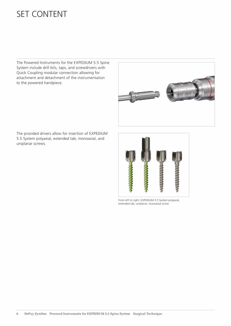
The Powered Instruments for the EXPEDIUM 5.5 Spine System include drill bits, taps, and screwdrivers with Quick Coupling modular connection allowing for attachment and detachment of the instrumentation to the powered handpiece.
The provided drivers allow for insertion of EXPEDIUM 5.5 System polyaxial, extended tab, monoaxial, and uniplanar screws.
From left to right: EXPEDIUM 5.5 System polyaxial, extended tab, uniplanar, monoaxial screw
SET CONTENT

Surgical Technique Powered Instruments for EXPEDIUM 5.5 Spine System DePuy Synthes 1
It is important to note that the Powered Instruments for the EXPEDIUM 5.5 Spine System are intended to be used to compliment the EXPEDIUM 5.5 System Core Instru-ment Set.
The EXPEDIUM 5.5 System Powered Instruments set are presented in three cases:• Graphic Case for Powered Instruments• Graphic Case for Power Handpiece• Transport Case for Universal Battery Charger II
and Batteries
For set content details, please refer to the product catalog at the end of this guide.
Graphic Case for Powered Instruments
Graphic Case for Power Handpiece
Transport Case for Universal Battery Charger II and Batteries

8 DePuy Synthes Powered Instruments for EXPEDIUM 5.5 Spine System Surgical Technique
Required Equipment
05.001.204 Universal Battery Charger II
532.103 Battery for Nos. 532.101 and 532.110
532.132 Battery Casing for Nos. 532.101 and 532.110, with Locking for Lid
532.104 Sterile Cover for Nos. 532.101 and 532.110
532.101 Colibri II
532.015 Quick Coupling for DHS/DCS Triple Reamers, for Nos. 532.001, 532.010, 532.101, 532.110 and 05.001.175
Before surgery, ensure the batteries of the handpiece are fully charged.
Warning: Only use the Synthes Universal Battery Charger II (05.001.204) to charge the batteries. Using another charger can damage the battery.
1. Charging the batteryPlace the battery to be charged in the proper direction into the corresponding slot of an empty charger bay. Only one battery can be charged in each charger bay at a time. All charger bays can, however, be used simulta-neously with any combination of battery types.
Once the battery types have been identified, the charging process starts automatically. This is signaled by the yellow charger display (Fig. 1).
Depending on the charge status and type of battery, it can take from about 15 minutes to around 60 minutes to charge.
Once the battery is fully charged, the green display lights up and the charger switches to maintenance charge (Fig. 2). The battery can be left in the charger. Leave the device switched on to ensure that the battery is always fully charged.
If the battery is removed from the charger before the green display lights up, it will not be fully charged.
Note: For additional instructions on the use of the Universal Battery Charger II, please refer to the Synthes Universal Battery Charger II Instructions for Use.
1 The section PRE-OPERATIVE PREPARATIONS (pages 8–12) has been extracted from the Colibri II Instructions for Use and the Universal Battery Charger II Instructions for Use.
Figure 1 Figure 2
PRE-OPERATIVE PREPARATIONS1

Surgical Technique Powered Instruments for EXPEDIUM 5.5 Spine System DePuy Synthes 9
2. Inserting the battery in the battery casingTo ensure sterility, the battery is to be inserted into the battery casing by two people, one of whom is wearing sterile garments:
The person with the sterile garments holds the sterile battery casing. If the casing is not opened, the same person presses the central button to unlock (Fig. 1), turns the lid sideways (90°) as indicated by the arrow (Fig. 2) and pulls to open (Fig. 3). Leave the locking mechanism swung outward.
The person wearing the sterile garments places the sterile cover on the battery casing (Fig. 4) and checks if it is seated correctly. The sterile cover ensures that the unsterile battery does not contact the outside of the sterile casing.
The person not wearing sterile garments carefully guides the unsterile battery through the sterile cover (Fig. 5). As an orientation, the two symbols on the battery and the sterile cover should face each other (Fig. 6). The same person presses it completely into the battery casing to ensure a correct seat (Fig. 7). This person may not contact the outside of the battery casing.
The person not wearing sterile garments grasps the flanges on the sterile cover and removes it from the battery casing (Fig. 8).
The person wearing the sterile garments closes the casing cover from the outside without contacting the battery or the inside of the casing. After having closed the casing cover, turn the lid sideways (90°) until it locks.
Figure 1 Figure 2
Figure 3 Figure 4
Figure 5 Figure 6
Figure 7 Figure 8

Figure 10
Figure 9
11 DePuy Synthes Powered Instruments for EXPEDIUM 5.5 Spine System Surgical Technique
Power Tools Colibri II
Precautions:• Normally, one battery is sufficient for one surgery.
A second battery pack (battery casing with the battery) should be kept ready to ensure fast intraoperative changing of batteries under sterile conditions if necessary.
• Never open a battery casing intraoperatively to insert a new battery. Always replace the whole battery pack with another battery pack, which should have been prepared before the start of the surgery.
• If the unsterile battery contacts the outside of the casing, the casing must be resterilised before being used in the OR.
• To close the casing cover, press it firmly to ensure that it is completely closed (Fig. 9 and 10) so that the locking mechanism properly engages. Always ensure that the cover is totally closed before using the system.
• Sterilize the sterile cover after each use to ensure aseptic conditions when inserting the unsterile battery into the sterile battery casing.
Inserting the battery pack into the power toolGuide the battery pack (battery casing with inserted battery) from below into the shaft of the handpiece (Fig. 11). The shape of the battery casing prevents the battery from being inserted incorrectly. Check if the battery pack is seated correctly by gently pulling on it.
Removing the battery pack from the power toolSimultaneously press the release buttons for the battery casing with one hand (Fig. 12) and use the other hand to remove the battery pack from the handpiece.
Figure 11 Figure 12

Surgical Technique Powered Instruments for EXPEDIUM 5.5 Spine System DePuy Synthes 11
3. Mounting the AttachmentThe attachment (532.015) contains gearing which decreases the speed of the handpiece while increasing torque. Insert the coupling into the handpiece. If the positioning pins do not lock in place right away, twist the attachment slightly until it locks into the correct position. Check if the attachment is seated correctly by gently pulling on it.
4. Removing the AttachmentPress the release buttons on the handpiece simultane-ously and remove the coupling.
Note: For further details about the charging process, battery insertion or attachment assembly and disassembly, please refer to: • Instructions for Use Colibri II• Instructions for Use Universal Battery Charger II
1
3
2
12 DePuy Synthes Powered Instruments for EXPEDIUM 5.5 Spine System Surgical Technique
Power Tools Colibri II
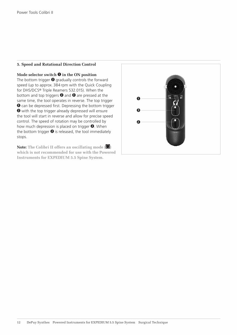
5. Speed and Rotational Direction Control Mode selector switch 1 in the ON positionThe bottom trigger 2 gradually controls the forward speed (up to approx. 384 rpm with the Quick Coupling for DHS/DCS® Triple Reamers 532.015). When the bottom and top triggers 2 and 3 are pressed at the same time, the tool operates in reverse. The top trigger 3 can be depressed first. Depressing the bottom trigger 2 with the top trigger already depressed will ensure the tool will start in reverse and allow for precise speed control. The speed of rotation may be controlled by how much depression is placed on trigger 2 . When the bottom trigger 2 is released, the tool immediately stops.
Note: The Colibri II offers an oscillating mode ( ) which is not recommended for use with the Powered Instruments for EXPEDIUM 5.5 Spine System.

Surgical Technique Powered Instruments for EXPEDIUM 5.5 Spine System DePuy Synthes 11
SCREW BED PREPARATION
Equipment
532.101 Colibri II
532.132 Battery Casing for Nos. 532.101 and 532.110, with Locking for Lid
532.103 Battery for Nos. 532.101 and 532.110
532.015 Quick Coupling for DHS/DCS Triple Reamers, for Nos. 532.001, 532.010, 532.101, 532.110 and 05.001.175
3100-02-100P Power B 2.4 mm Drill Bit, short,
Quick Coupling
3100-02-105P Power B 2.4 mm Drill Bit, medium,
Quick Coupling
3100-02-205P Power B 3.2 mm Drill Bit, medium,
Quick Coupling
3100-02-210P Power B 3.2 mm Drill Bit, long,
Quick Coupling
EXPEDIUM System Core Instruments
2750-10-140/160 Ball Tip feeler, Straight/Curved
Identify screw entry point and penetrate the cortex using a suitable instrument (awl, rongeur, high speed burr or equivalent).
Note: Cannulation using the Powered Instruments represents an optional step in the procedure. Depending on surgeon preference, cannulation can be completed using the EXPEDIUM System core instruments.
Drill bits are available in two diameters and three lengths to provide the surgeon the option to choose a suitable instrument based upon the vertebral level and patient size.
Note: To ensure full screw thread purchase, it is recommended to use a B 2.4 mm drill bit when pre-paring a pedicle for the placement of a B 4.35 mm screw. For B 5 mm and larger diameter screws, a B 2.4 mm or a B 3.2 mm drill bit is acceptable.
CANNULATION

14 DePuy Synthes Powered Instruments for EXPEDIUM 5.5 Spine System Surgical Technique
Cannulation
To connect the drill bit to the Quick Coupling, push the outer ring away from the powered handpiece and insert the drill until the hexagonal flange is flush with the Quick Coupling. Check if the drill bit is retained by gently pulling on it.
Make sure the mode selector switch of the powered handpiece is in the ON position.
Apply the drill bit to the entry point of the bone and depress lower trigger until a cannulation of desired depth is attained.
10 mm
10 mm
10 mm
30 mm
Surgical Technique Powered Instruments for EXPEDIUM 5.5 Spine System DePuy Synthes 15
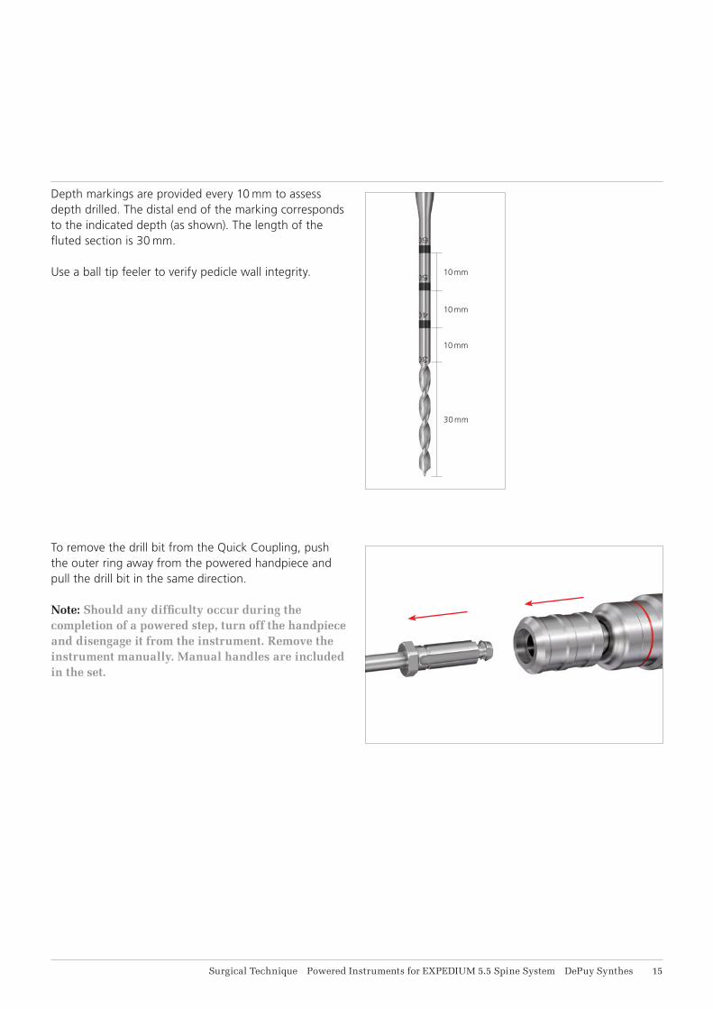
Depth markings are provided every 10 mm to assess depth drilled. The distal end of the marking corresponds to the indicated depth (as shown). The length of the fluted section is 30 mm.
Use a ball tip feeler to verify pedicle wall integrity.
To remove the drill bit from the Quick Coupling, push the outer ring away from the powered handpiece and pull the drill bit in the same direction.
Note: Should any difficulty occur during the completion of a powered step, turn off the handpiece and disengage it from the instrument. Remove the instrument manually. Manual handles are included in the set.
16 DePuy Synthes Powered Instruments for EXPEDIUM 5.5 Spine System Surgical Technique
Tapping
TAPPINGRequired Equipment
532.101 Colibri II
532.132 Battery Casing for Nos. 532.101 and 532.110, with Locking for Lid
532.103 Battery for Nos. 532.101 and 532.110
532.015 Quick Coupling for DHS/DCS Triple Reamers, for Nos. 532.001, 532.010, 532.101, 532.110 and 05.001.175
Power EXPEDIUM System Double Lead Taps, Quick Coupling
2997-04-040P 4.35 mm, short
2997-04-050P 5.00 mm, short
2997-04-060P 6.00 mm, short
2997-04-061P 6.00 mm, medium
2997-04-070P 7.00 mm, medium
2997-04-080P 8.00 mm, long
2997-04-090P 9.00 mm, long
2997-04-010P 10.00 mm, long
Power EXPEDIUM System Single Lead Taps, Quick Coupling
2797-02-450P 4.35 mm, short
2797-02-550P 5.00 mm, short
2797-02-650P 6.00 mm, short
2797-02-651P 6.00 mm, medium
2797-02-750P 7.00 mm, medium
2797-02-850P 8.00 mm, medium
EXPEDIUM System Core Instruments
2750-10-140/160 Ball Tip feeler, Straight/Curved
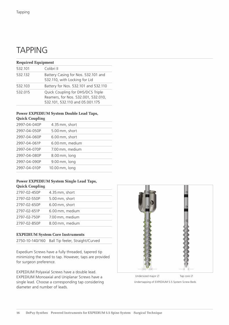
Expedium Screws have a fully threaded, tapered tip minimizing the need to tap. However, taps are provided for surgeon preference.
EXPEDIUM Polyaxial Screws have a double lead. EXPEDIUM Monoaxial and Uniplanar Screws have a single lead. Choose a corresponding tap considering diameter and number of leads.
Undersized major B
Undertapping of EXPEDIUM 5.5 System Screw Beds
Tap core B

Surgical Technique Powered Instruments for EXPEDIUM 5.5 Spine System DePuy Synthes 11
Clear the surrounding soft tissue and bony anatomy to allow for full screw angulation.
Tap design incorporates a degree of undertapping. To choose the appropriate tap size, reference the Tap Dimension Table for values to determine the amount of undertapping.
Note: 6 mm taps are offered in two lengths to provide the surgeon the option to choose a suitable instru-ment based upon the vertebral level and patient size.
For diameter 8 mm screws and larger, it is recommended to apply a sequential tapping procedure. Start with a smaller tap diameter and complete sequentially tapping steps, increasing tap diameter until the desired screw diameter is reached. It is recommended to limit the change in hole diameter by one size and to tap to the full length of the screw intended to be placed.
Note: In order to decrease the amount of torque re quired for large diameter screws, the degree of undertapping is reduced for 8 mm taps and larger. Reference the EXPEDIUM 5.5 System Tap Dimension Table for values.
To connect the tap to the Quick Coupling, push the outer ring away from the powered handpiece and insert the tap until the hexagonal flange is flush with the Quick Coupling. Verify that the tap is retained by gently pulling on it.
The handpiece has a proportional trigger control, meaning that the further the trigger is depressed, the faster the tap will be rotated.
Make sure the mode selector switch of the powered handpiece is in the ON position.
Apply the instrument to the entry point of the cannu-lation and depress lower trigger until tapped to desired depth.
Screw/Tap Undersizing
Screw Size Major B Minor B Tap Core B 4.35 mm 0.2 mm 0.6 mm 2.5 mm 5 mm 0.2 mm 0.75 mm 2.9 mm 6 mm 0.2 mm 0.75 mm 3.3 mm 7 mm 0.2 mm 0.75 mm 3.7 mm 8 mm 0.15 mm 0.2 mm 4.9 mm 9 mm 0.15 mm 0.2 mm 5.9 mm10 mm 0.15 mm 0.2 mm 6.9 mm
EXPEDIUM 5.5 System Tap Dimension Table
Tap SizeMaximum Tapping DepthDouble Lead Single Lead
4.35 mm 40 mm 40 mm 5 mm 50 mm 50 mm 6 mm 60 mm 60 mm 7 mm 70 mm 70 mm 8 mm 130 mm 70 mm 9 mm 130 mm
n. a.10 mm 130 mm
EXPEDIUM 5.5 System Maximum Tapping Depth Table

10 mm
10 mm
10 mm
30 mm
1 2
18 DePuy Synthes Powered Instruments for EXPEDIUM 5.5 Spine System Surgical Technique
Tapping
Depth markings are provided every 10 mm to assess tapped depth. The distal end of the marking corre-sponds to the indicated depth. The threaded portion is 30 mm long.
To withdraw the tap from the bone, operate the handpiece in the reverse (counterclockwise) direction. As shown, first depress the top trigger and then depress the bottom trigger to avoid inadvertent advancement of the tap.
Use a ball tip feeler to verify cannulation wall integrity and assess hole depth.
To remove the tap from the Quick Coupling push the outer ring away from the powered handpiece and then remove the tap.
Note: Should any difficulty occur during the completion of a powered step, turn off the handpiece and disengage it from the instrument. Remove the instrument manually. Manual handles are included in the set.

Surgical Technique Powered Instruments for EXPEDIUM 5.5 Spine System DePuy Synthes 19
SCREW DELIVERY
Required Equipment
532.101 Colibri II
532.132 Battery Casing for Nos. 532.101 and 532.110, with Locking for Lid
532.103 Battery for Nos. 532.101 and 532.110
532.015 Quick Coupling for DHS/DCS Triple Reamers, for Nos. 532.001, 532.010, 532.101, 532.110 and 05.001.175
3100-02-150P Power EXPEDIUM 5.5 Poly Driver Handle
3100-02-155P Power EXPEDIUM 5.5 Poly Driver Shaft
3100-02-160P Power EXPEDIUM 5.5 Poly Driver Sleeve
2797-12-830P Power EXPEDIUM 5.5 Monoaxial Driver
2797-03-150P Power Ratcheting T-Handle, Quick Coupling
Optional Equipment
2797-03-140P Power Ratcheting Elliptical Handle, Quick Coupling
Choose desired screw type, length, and diameter. Note: It is not recommended to use screw diameters and lengths outside of the range of provided taps.
To improve surgical flow and minimize non-operative time, two polyaxial and two monoaxial drivers are included in the set to enable concurrent screw loading and screw placement.

21 DePuy Synthes Powered Instruments for EXPEDIUM 5.5 Spine System Surgical Technique
Poly Driver Assembly (Polyaxial or Uniplanar Screws)
POLY DRIVER ASSEMBLY (POLYAXIAL OR UNIPLANAR SCREWS)If desired, assemble the Poly Driver Sleeve (3100-02-160P) to the Poly Driver Handle (3100-02-150P) by de-pressing the release levers and sliding the sleeve towards the handle (recommended). For use with Polyaxial and Uniplanar screws, engage the sleeve in the more proximal position. The sleeve should abut the handle and the etch “EXT TAB” should NOT be visible.
The gold color band on the instrument corresponds to compatibility with EXPEDIUM 5.5 System Single Innie screws.
Insert the Driver Shaft (3100-02-155P) into the handle and advance until the handle engages the shaft. The first engaging position is intended for use with Polyaxial and Uniplanar screws. The etch “EXT TAB” should NOT be visible on the Driver Shaft.

Surgical Technique Powered Instruments for EXPEDIUM 5.5 Spine System DePuy Synthes 21
POLY DRIVER ASSEMBLY (EXTENDED TAB SCREWS)
Insert the Driver Shaft (3100-02-155P) into the handle and advance Driver Shaft to the second engaging position. The etch “EXT TAB” SHOULD be visible on the Driver Shaft.
Assemble the Poly Driver Sleeve (3100-02-160P) to the Poly Driver Handle (3100-02-150P) by sliding the sleeve towards the handle until it engages the Poly Driver Handle. Ensure the sleeve is engaged in the more distal position and the etch “EXT TAB” is visible.
The Poly Driver Sleeve is used to protect the tabs during screw insertion.
The gold color band on the instrument corresponds to compatibility with EXPEDIUM 5.5 System Single Innie screws.
22 DePuy Synthes Powered Instruments for EXPEDIUM 5.5 Spine System Surgical Technique
Loading Polyaxial, Uniplanar or Extended Tab Screws
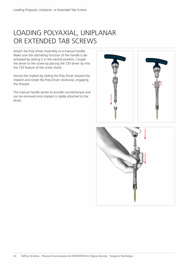
Attach the Poly Driver Assembly to a manual handle. Make sure the ratcheting function of the handle is de-activated by setting it in the neutral position. Couple the driver to the screw by placing the T20 driver tip into the T20 feature of the screw shank.
Secure the implant by sliding the Poly Driver toward the implant and rotate the Poly Driver clockwise, engaging the threads.
The manual handle serves to provide countertorque and can be removed once implant is rigidly attached to the driver.
LOADING POLYAXIAL, UNIPLANAR OR EXTENDED TAB SCREWS

Surgical Technique Powered Instruments for EXPEDIUM 5.5 Spine System DePuy Synthes 21
Attach the Poly Driver and screw assembly to the Quick Coupling of the powered handpiece. Verify if the instrument is retained correctly by gently pulling on it.

1 2
24 DePuy Synthes Powered Instruments for EXPEDIUM 5.5 Spine System Surgical Technique
Delivering a Polyaxial Screw
The handpiece has a proportional trigger control, meaning that the further the trigger is depressed, the faster the screw will be rotated.
Apply the instrument to the entry point of the pedicle and depress lower trigger until the screw is inserted to the desired depth. Once the pedicle screw is inserted, make sure the polyaxial head does not interfere with the bony anatomy and polyaxiality of head is retained.
If a screw needs to be adjusted or removed from the bone, operate the handpiece in the reverse (counter-clockwise) direction. As shown, first depress the top trigger and then depress the bottom trigger to avoid inadvertent advancement of the screw.
Note: For fine screw height adjustment, alternatively a manual handle can be used.
DELIVERING A POLYAXIAL SCREW

Surgical Technique Powered Instruments for EXPEDIUM 5.5 Spine System DePuy Synthes 25
To release the implant, turn the handle of the Poly Driver counterclockwise to disengage the driver from the screw head.
Disconnect the Poly Driver from the Quick Coupling by pushing the outer ring away from the powered hand-piece and then removing the instrument. The second Poly Driver should be preloaded and ready to insert the subsequent screw.
Note: Should any difficulty arise from the powered handpiece or instruments during the performance of the procedure, turn off the handpiece and disen-gage the instrument from the Quick Coupling. Remove the instrument using a manual handle.
26 DePuy Synthes Powered Instruments for EXPEDIUM 5.5 Spine System Surgical Technique
Loading a Monoaxial Screw
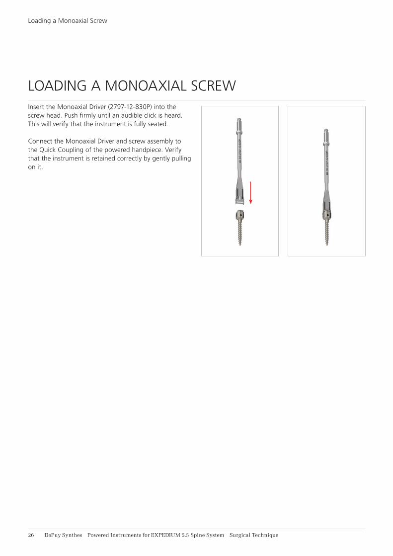
Insert the Monoaxial Driver (2797-12-830P) into the screw head. Push firmly until an audible click is heard. This will verify that the instrument is fully seated.
Connect the Monoaxial Driver and screw assembly to the Quick Coupling of the powered handpiece. Verify that the instrument is retained correctly by gently pulling on it.
LOADING A MONOAXIAL SCREW

1 2
Surgical Technique Powered Instruments for EXPEDIUM 5.5 Spine System DePuy Synthes 21
The handpiece has a proportional trigger control, meaning that the further the trigger is depressed, the faster the screw will be rotated.
Apply the instrument to the entry point of the pedicle and depress lower trigger until the screw is inserted to the desired depth.
DELIVERING A MONOAXIAL SCREW
If a screw needs to be adjusted or removed from the bone, operate the handpiece in the reverse (counter-clockwise) direction. As shown, first depress the top trigger and then depress the bottom trigger to avoid inadvertent advancement of the screw.
Note: For fine screw height adjustment, alternatively a manual handle can be used.

28 DePuy Synthes Powered Instruments for EXPEDIUM 5.5 Spine System Surgical Technique
Delivering a Monoaxial Screw
To release the implant, retract the screwdriver from the monoaxial screw.
Disconnect the Monoaxial Driver from the Quick Coupling by pushing the outer ring away from the powered handpiece and then removing the instrument. The second Monoaxial Driver should be preloaded and ready to insert the subsequent screw.
Note: Should any difficulty arise from the powered handpiece or instruments during the performance of the procedure, turn off the hand-piece and disen-gage the instrument from the Quick Coupling. Remove the instrument using a manual handle.

Surgical Technique Powered Instruments for EXPEDIUM 5.5 Spine System DePuy Synthes 29
MANUAL OPERATION
A Ratcheting T-Handle (2797-03-150P) and a Ratcheting Elliptical Handle (2797-03-140P) with a Quick Coupling have been included in this set to allow for manual completion of tapping or screw delivery. The manual handles can also be used for screw head height adjust-ment.
Both manual handles have clockwise and counter-clock-wise ratcheting as well as a lock position. The direction or lock can be selected by turning the ring at the base of the handle.

1
1
11 DePuy Synthes Powered Instruments for EXPEDIUM 5.5 Spine System Surgical Technique
Proper handling and maintenance help to extend the useful life of surgical instruments. Gentle care and maintenance with proper lubrication can substantially increase the reliability and life of the system compo-nents.
Special care has to be applied for regular lubrication of the power handpiece, the Battery Casing, the attachment and the manual handles. For instruction for lubrication of the powered device please refer to the Colibri II Instructions for Use. The manual handles are lubricated with 1 drop of stan-dard autoclavable oil at the marked points. Lubricate the unlocking ring of the Quick Coupling. Distribute the oil by moving it back and forth several times. Wipe off the excess oil with a cloth.
Note: The batteries and the Universal Battery Charger should not be sterilized at any time.
For further details about the reprocessing and the main-tenance of the Powered Instruments please refer to:
• Colibri II Instructions for Use• Colibri /Colibri II Care and Maintenance Poster• Universal Battery Charger II Instructions for Use • Instructions for Use and Reprocessing Instructions
for Surgical Instruments 0902-90-044 For general guidelines, function control and dismantling of multi-part instruments, as well as processing guidelines for implants, please contact your local sales re presentative or refer to: www.synthes.com/cleaning-sterilization
PROCESSING, REPROCESSING, CARE AND MAINTENANCE

Surgical Technique Powered Instruments for EXPEDIUM 5.5 Spine System DePuy Synthes 11
PRODUCT CATALOG
Cases and Trays
Case 1
3100-06-100P Power EXPEDIUM 5.5 Case for Ped Prep, Screw & Set Screw Insertion
3100-06-150P Power EXPEDIUM 5.5 Tray for Ped Prep, Screw & Set Screw Insertion
3100-06-105P Power EXPEDIUM Double Lead Tap Caddie
3100-06-110P Power EXPEDIUM Single Lead Tap Caddie
2797-92-109 EXPEDIUM Instruments Case Generic Lid
Case 2
60.692.001 Graphic Case for Power Handpiece
60.600.007 Graphic Case Generic Lid
Case 3
60.692.016 Transport Case for DePuy Synthes Universal Battery Charger II and Batteries

12 DePuy Synthes Powered Instruments for EXPEDIUM 5.5 Spine System Surgical Technique
Delivering a Monoaxial Screw
Drill Bits
3100-02-100P Power B2.4 mm Drill Bit, short, Quick Coupling
3100-02-105P Power B2.4 mm Drill Bit, medium, Quick Coupling
3100-02-205P Power B3.2 mm Drill Bit, medium, Quick Coupling
3100-02-210P Power B3.2 mm Drill Bit, long, Quick Coupling
Taps for EXPEDIUM System Polyaxial Screws (Double Lead)
2997-04-040P Power EXPEDIUM 4.35 mm Double Lead Tap, Short, Quick Coupling
2997-04-050P Power EXPEDIUM 5.00 mm Double Lead Tap, Short, Quick Coupling
2997-04-060P Power EXPEDIUM 6.00 mm Double Lead Tap, Short, Quick Coupling
2997-04-061P Power EXPEDIUM 6.00 mm Double Lead Tap, Medium, Quick Coupling
2997-04-070P Power EXPEDIUM 7.00 mm Double Lead Tap, Medium, Quick Coupling
2997-04-080P Power EXPEDIUM 8.00 mm Double Lead Tap, Long, Quick Coupling
2997-04-090P Power EXPEDIUM 9.00 mm Double Lead Tap, Long, Quick Coupling
2997-04-010P Power EXPEDIUM 10.00 mm Double Lead Tap, Long, Quick Coupling
Short: 100 mm, Medium: 150 mm, Long: 200 mm
Short: 100 mm, Medium: 150 mm, Long: 200 mm
Surgical Technique Powered Instruments for EXPEDIUM 5.5 Spine System DePuy Synthes 11
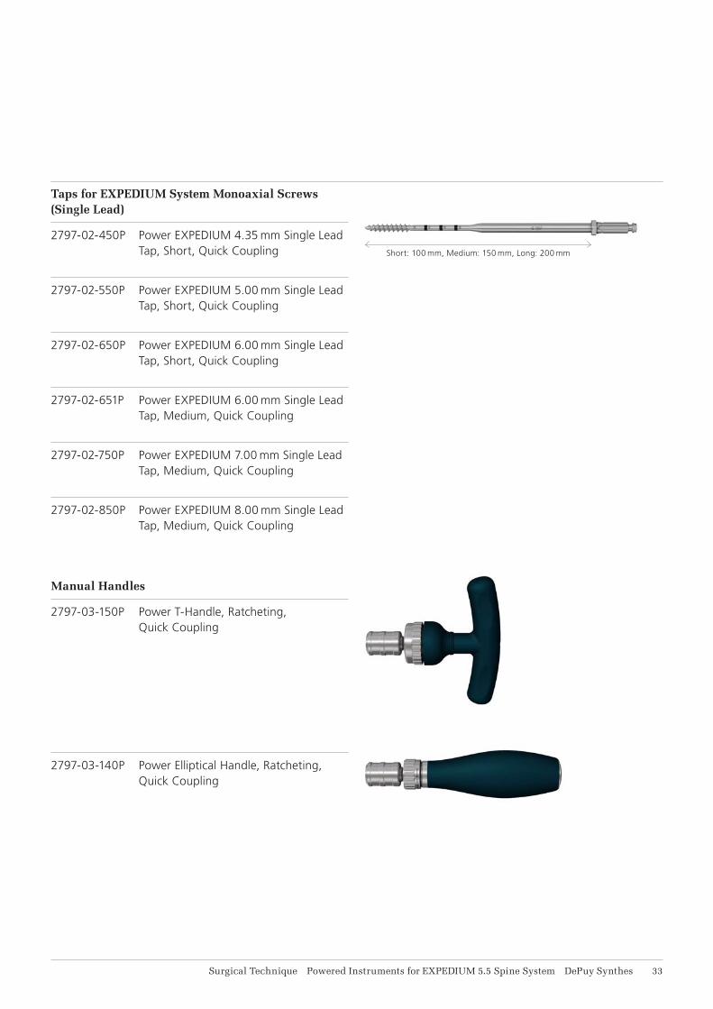
Taps for EXPEDIUM System Monoaxial Screws (Single Lead)
2797-02-450P Power EXPEDIUM 4.35 mm Single Lead Tap, Short, Quick Coupling
2797-02-550P Power EXPEDIUM 5.00 mm Single Lead Tap, Short, Quick Coupling
2797-02-650P Power EXPEDIUM 6.00 mm Single Lead Tap, Short, Quick Coupling
2797-02-651P Power EXPEDIUM 6.00 mm Single Lead Tap, Medium, Quick Coupling
2797-02-750P Power EXPEDIUM 7.00 mm Single Lead Tap, Medium, Quick Coupling
2797-02-850P Power EXPEDIUM 8.00 mm Single Lead Tap, Medium, Quick Coupling
Manual Handles
2797-03-150P Power T-Handle, Ratcheting, Quick Coupling
2797-03-140P Power Elliptical Handle, Ratcheting, Quick Coupling
Short: 100 mm, Medium: 150 mm, Long: 200 mm

14 DePuy Synthes Powered Instruments for EXPEDIUM 5.5 Spine System Surgical Technique
Delivering a Monoaxial Screw
Screwdrivers
3100-02-150P Power EXPEDIUM 5.5 Poly Driver, Handle
3100-02-155P Power EXPEDIUM 5.5 Poly Driver, Shaft, Quick Coupling
3100-02-160P Power EXPEDIUM 5.5 Poly Driver, Sleeve
2797-12-830P Power EXPEDIUM 5.5 Monoaxial Driver, Quick Coupling

Surgical Technique Powered Instruments for EXPEDIUM 5.5 Spine System DePuy Synthes 15
Power Tool handpiece and Batteries
532.101 Colibri II
532.015 Quick Coupling for DHS/DCS Triple Reamers, for Nos. 532.001, 532.010, 532.101, 532.110 and 05.001.175
532.103 Battery for Nos. 532.101 and 532.110
532.132 Battery Casing for Nos. 532.101 and 532.110, with Locking for Lid
532.104 Sterile Cover for Nos. 532.101 and 532.110
05.001.204 Universal Battery Charger II

16 DePuy Synthes Powered Instruments for EXPEDIUM 5.5 Spine System Surgical Technique
Delivering a Monoaxial Screw
Reprocessing
68.001.610 Washing Basket, size 1/1, for Colibri (II) and Small Battery Drive (II)
68.001.602 Lid for Washing Basket, size 1/1
519.400 Cleaning Brush for Compact Air Drive, Power Drive, Colibri (II) and Small Electric Drive
519.970 Synthes Special Oil, 40 ml


DePuy International, Ltd.St Anthony’s RoadLeedsLS11 8DTUnited Kingdom
Medos International SARLChemin-Blanc 382400 Le LocleSwitzerland
DePuy Spine Inc.325 Paramount DriveRaynham, MA 02767USA
EC REP
0086 © D
ePuy
Syn
thes
Spi
ne, a
div
isio
n of
Joh
nson
& J
ohns
on M
edic
al L
td. 2
016.
A
ll rig
hts
rese
rved
. D
SE
M/S
PN
/111
4/02
19(1
) 02
/16
For recognized manufacturer, refer to product label.
This publication is not intended for distribution in the USA.
All surgical techniques are available as PDF files at www.depuysynthes.com


