USE ONLY HAYWARD GENUINE REPLACEMENT PARTS 1 PowerFlo LX ™ / PowerFlo II ™ / EP Pump Series Owner’s Manual INSTALLATION, OPERATION, & PARTS IMPORTANT SAFETY INSTRUCTIONS Hayward Pool Products 620 Division Street, Elizabeth, NJ 07207 Phone: (908) 355-7995 www.haywardnet.com Contents Product Warnings……….………2 Installation……….……………..…4 Start-Up & Operation…….…….6 Shaft Seal Replacement……….7 Troubleshooting…………………..8 Replacement Parts………..….…10 Warranty …………………………..…11 Registration………………………….12 ISPFSERIES Rev G Basic safety precautions should always be followed, including the following: Failure to follow instructions can cause severe injury and/or death. This is the safety-alert symbol. When you see this symbol on your equipment or in this manual, look for one of the following signal words and be alert to the potential for personal injury. WARNING warns about hazards that could cause serious personal injury, death or major property damage and if ignored presents a potential hazard. CAUTION warns about hazards that will or can cause minor or moderate personal injury and/or property damage and if ignored presents a potential hazard. It can also make consumers aware of actions that are unpredictable and unsafe. The NOTICE label indicates special instructions that are important but not related to hazards.
Transcript
USE ONLY HAYWARD GENUINE REPLACEMENT PARTS 1
PowerFlo LX™ / PowerFlo II™ / EP
Pump Series
Owner’s Manual
INSTALLATION, OPERATION, & PARTS
IMPORTANT SAFETY INSTRUCTIONS
Hayward Pool Products620 Division Street, Elizabeth, NJ 07207
Phone: (908) 355-7995 www.haywardnet.com
Contents Product Warnings……….………2
Installation……….……………..…4
Start-Up & Operation…….…….6
Shaft Seal Replacement……….7
Troubleshooting…………………..8
Replacement Parts………..….…10
Warranty …………………………..…11
Registration………………………….12
ISPFSERIES Rev G
Basic safety precautions should always be followed, including the following: Failure to follow instructions can cause severe injury and/or death.
This is the safety-alert symbol. When you see this symbol on your equipment or in this manual, look for one of the following signal words and be alert to the potential for personal injury.
WARNING warns about hazards that could cause serious personal injury, death or major property damage and if ignored presents a potential hazard.
CAUTION warns about hazards that will or can cause minor or moderate personal injury and/or property damage and if ignored presents a potential hazard. It can also make consumers aware of actions that are unpredictable and unsafe.
The NOTICE label indicates special instructions that are important but not related to hazards.
WAR
to follow
WARSuction in ssevere inju
Hair EntrapLimb Entracracked, mBody SuctiEvisceratiosump or sudisemboweMechanicaopening of
WARo W
beap
o Do Do Tho No Reo In
guo In
WARfrom the s
WARand other
WARfrequentlysecurely a
CAUprevent th
WAR
WAR
WARall times. Cas a means
WARstart up, nofollow safeand clamp pool and spbe in open back to theopen filter is discharg
RNING - Reainstructions
RNING – Suc
suction outlets ry and/or death
pment- Hair canapment- A limb issing, or not sion Entrapmenon/ Disembowuction outlet covelment. al Entrapment-a suction outle
RNING - To Re
When outlets aree installed. Sucpart, as measurual suction fittiual suction fittihe maximum syever use Pool oeplace damage
n addition two ouidelines, follow
nstallation of a v
RNING – Failsuction outle
RNING – Fair material can
RNING – Sucy and replaceattached.
TION – Comheir being us
RNING – Nev
RNING – Nev
RNING – To reComponents sus of access to th
RNING – Hazormal operationty and operatiodue to pressure
pa water circulaposition. Befo
e pool. Do not cmanual air relieed.
USE
ad and follocan cause se
ction Entrapm
and/or suctionh due to the fol
n become entaninserted into aecurely attache
nt- A negative pelment - A negver which is, da
There is potenet cover resultin
educe the ris
e small enough ction outlets inred from near pngs shall be plngs shall not b
ystem flow rate or Spa if any suced, broken, cracor more suctionw all National, vacuum release
lure to removets can result
lure to keep sn result in an
ction outlet ced at least ev
mponents sucsed as means
ver operate or
ver change th
educe risk of injuch as the filtrathe pool.
zardous Pressn, and after pumon instructions e in the systemation system, are starting syst
change filter coef valve. Do no
E ONLY HAY
ow all instrevere injury a
ment Hazard.
n outlet covers wlowing entrapm
ngled in suctionan opening of a ed can result in ressure applied
gative pressure amaged, broken
tial for jewelry,ng in mechanica
sk of Entrapm
to be blocked the same plan
point to near poaced in such loe located on seshall not excee
ction outlet comcked, missing, o outlets per pumState, and Locae or vent system
ve pressure tet in an increa
suction outle increase pot
components hvery ten years
ch as the filtras of access to
r test the circ
e filter contro
jury, do not pertion system, pu
sure. Pool andmp shut off. Stacould result in , which could cll system and pem pump, all sntrol valve post close filter ma
YWARD GEN
ructions in tnd/or death.
which are, damment hazards:
n outlet cover.suction outlet a mechanical b
d to a large portapplied directlyn, cracked, mis
swimsuit, hairal entrapment.
ment Hazards:
by a person, a me (i.e. floor or wint.
ocations and diseating areas or ed the flow ratinmponent is damor not securely mp installed inal codes applicam, which relieve
est plugs andse potential f
et componenttential for su
have a finite s or if found t
ation systemo the pool by
culation syste
ol valve posit
rmit children to umps, and heat
d spa water circand clear of circviolent separat
cause property pump controls mystem valves mition while systanual air relief v
NUINE REPLA
this owner’s .
maged, broken,
sump or suctiobind or swellingtion of the bodyy to the intestin
ssing, or unsecu
r decorations, fi
: minimum of tw
wall), must be i
stances to avoion the backresng as listed on
maged, broken, attached suctio accordance wiable. es entrapping s
d/or plugs usfor suction e
ts clear of deuction entrapm
life, the coveto be damage
, pumps andyoung childr
em at more th
tion while th
use or climb oters must be po
culation systemculation systemtion of the pumdamage, sever
must be in off pmust be set in atem pump is ruvalve until a ste
ACEMENT PA
manual and o
cracked, missi
on outlet cover tg of the limb. y or limbs can rnes through an ured can result
inger, toe or kn
wo functioning snstalled a mini
id “dual blockast for such seatithe suction out cracked, mission outlet compith latest ASME
suction, is reco
sed in winterintrapment as
ebris, such asment as desc
er/grate shoued, broken, c
heater mustren.
han 30 PSI.
e pump is ru
n this product. ositioned to pre
ms operate undem equipment du
p housing and re personal injuposition and filt
position to allonning. Before seady stream of
ARTS
on the equip
ng, or unsecure
that is damaged
result in an entunprotected suin evisceration
uckle to be cau
suction outlets mum of three f
age” by a user.ing areas. tlet cover. ing, or not secuonents immedi
E, APSP Standar
mmended.
ization of thes described a
s leaves, dirt,cribed above
uld be inspeccracked, miss
t be positione
nning.
Closely supervevent children f
er hazardous pruring pump stacover, and/or f
ury, or death. Bter manual air row system watestarting systemwater (not air o
ment. Failure
ed can cause
d, broken,
rapment. uction outlet
n/
ught in an
per pump mustfeet (3’) [1 mete
urely attached.iately. rds and CPSC
e pool/spa above.
, hair, paper .
cted sing, or not
ed so as to
vise children atrom using them
ressure during rt up. Failure tofilter housing efore servicing elief valve muser to return
m pump, fully or air and water
2
e
t er]
t m
o
t
r)
USE ONLY HAYWARD GENUINE REPLACEMENT PARTS 3
WARNING – Separation Hazard. Failure to follow safety and operation instructions could result in violent separation of pump and/or filter components. Strainer cover must be properly secured to pump housing with strainer cover lock ring. Before servicing pool and spa circulation system, filters manual air relief valve must be in open position. Do not operate pool and spa circulation system if a system component is not assembled properly, damaged, or missing. Do not operate pool and spa circulation system unless filter manual air relief valve body is in locked position in filter upper body.
WARNING – Risk of Electric Shock. All electrical wiring MUST be in conformance with applicable local codes, regulations, and the National Electric Code (NEC). Hazardous voltage can shock, burn, and cause death or serious property damage. To reduce the risk of electric shock, do NOT use an extension cord to connect unit to electric supply. Provide a properly located electrical receptacle. Before working on any electrical equipment, turn off power supply to the equipment.
WARNING – To reduce the risk of electric shock replace damaged wiring immediately. Locate conduit to prevent abuse from lawn mowers, hedge trimmers and other equipment.
WARNING – Electrical ground all electrical equipment before connecting to electrical power supply. Failure to ground all electrical equipment can cause serious or fatal electrical shock hazard.
WARNING – Do NOT ground to a gas supply line.
WARNING – To avoid dangerous or fatal electrical shock, TURN OFF POWER to all electrical equipment before working on electrical connections.
WARNING – Failure to bond all electrical equipment to pool structure will increase risk for electrocution and could result in injury or death. To reduce the risk of electric shock, see installation instructions and consult a professional electrician on how to bond all electrical equipment. Also, contact a licensed electrician for information on local electrical codes for bonding requirements. Notes to electrician: Use a solid copper conductor, size 8 or larger. Run a continuous wire from external bonding lug to reinforcing rod or mesh. Connect a No. 8 AWG (8.4 mm2) [No. 6 AWG (13.3 mm2) for Canada] solid copper bonding wire to the pressure wire connector provided on the electrical equipment and to all metal parts of swimming pool, spa, or hot tub, and metal piping (except gas piping), and conduit within 5 ft. (1.5 m) of inside walls of swimming pool, spa, or hot tub. IMPORTANT - Reference NEC codes for all wiring standards including, but not limited to, grounding, bonding and other general wiring procedures.
WARNING – Risk of Electric Shock. Connect only to a branch circuit protected by a ground-fault circuit-interrupter (GFCI). Contact a qualified electrician if you cannot verify that the circuit is protected by a GFCI.
WARNING – Risk of Electric Shock . The electrical equipment must be connected only to a supply circuit that is protected by a ground-fault circuit-interrupter (GFCI). Such a GFCI should be provided by the installer and should be tested on a routine basis. To test the GFCI, push the test button. The GFCI should interrupt power. Push reset button. Power should be restored. If the GFCI fails to operate in this manner, the GFCI is defective. If the GFCI interrupts power to the electrical equipment without the test button being pushed, a ground current is flowing, indicating the possibility of an electrical shock. Do not use this electrical equipment. Disconnect the electrical equipment and have the problem corrected by a qualified service representative before using.
CAUTION – This pump is intended for use with permanently-installed pools and may be used with hot tubs and spas if so marked. Do not use with storable pools. A permanently-installed pool is constructed in or on the ground or in a building such that it cannot be readily disassembled for storage. A storable pool is constructed so that it is capable of being readily disassembled for storage and reassembled to its original integrity.
SAVE THESE INSTRUCTIONS
USE ONLY HAYWARD GENUINE REPLACEMENT PARTS 4
Installation Instructions Pump Location The PowerFlo LX™ and EP series pumps MUST be installed below the pool water line (see Figure to right).
Self-priming PowerFlo II™ pumps may be installed up to four (4) feet above the pool water line.
Install pump on a firm, level base or pad to meet all local and national codes. The field supplied base or pad must be level and vibration-free.
Pump motors require free circulation of air for cooling.
Do NOT install pump in a damp or non-ventilated location.
Though the pump is designed for outdoor use, it is strongly advised to protect the electrical components from the weather. Select a well-drained area, one that will not flood when it rains.
Pump Mounting Fasten pump to base or pad with screws or bolts to further reduce vibration and stress on pipe or hose joints. The base MUST be solid - level - rigid - vibration free. Pump mount must:
Allow pump inlet height to be as close to water level as possible. Allow use of short, direct suction pipe (to reduce friction losses). Allow for ball valves in suction and outlet piping. Be protected from excess moisture and flooding. Allow adequate access for servicing pump and piping.
Plumbing Use TFE tape to seal threaded connections on molded plastic components. All plastic fittings must be new or thoroughly cleaned before use. NOTE: Do NOT use Plumber’s Pipe Dope as it may cause cracking of the plastic components.
When applying TFE tape to plastic threads, wrap the entire threaded portion of the male fitting with one to two layers of tape. Wind the tape clockwise as you face the open end of the fitting, beginning at the end of the fitting.
The pump suction and outlet ports have molded-in thread stops. Do NOT attempt to force hose connector fitting past this stop. It is only necessary to tighten fittings enough to prevent leakage. Tighten fitting by hand and then use a tool to engage fitting an additional 1 ½ turns. Use care when using TFE tape as friction is reduced considerably; do NOT over-tighten fitting or you may cause damage. If leaks occur, remove connector, clean off old Teflon tape, re-wrap with one to two additional layers of TFE tape, and re-install connector. Piping - Flexible Hose, PVC, or Reinforced Hose are all acceptable piping methods For pump outlet use 1-1/2" PVC pipe or reinforced hose. For pump suction on ALL models, use 1-1/2" reinforced hose. Increase size if a long run is needed. For pipe larger than port, use reducing fitting in strainer port. To avoid pump strain, support suction and outlet independently. Place supports near pump. To avoid strain left by a gap at last connection, start all piping at pump and run pipe AWAY from pump. NEVER use suction pipe SMALLER than pump suction connections. Suction pipe inlet must be lower than pump inlet port.
USE ONLY HAYWARD GENUINE REPLACEMENT PARTS 5
Fittings Fittings restrict flow. For better efficiency, use the fewest possible fittings. Avoid fittings that could cause an air trap.
Electrical
WARNING – Ground motor before connecting to electrical power supply. Failure to ground pump motor can cause serious or fatal electrical shock hazard.
WARNING – Do NOT ground to a gas supply line. WARNING – To avoid dangerous or fatal electrical shock, turn OFF power to motor before
working on electrical connections. WARNING – Ground Fault Circuit Interrupter (GFCI) tripping indicates electrical problem. If
GFCI trips and won’t reset, consult electrician to inspect and repair electrical system. WARNING – Fire Hazard. Match supply voltage to motor nameplate voltage.
Insure that the electrical supply available agrees with the motor’s voltage, phase, and cycle, and that the wire size is adequate for the H.P. (KW) rating and distance from the power source.
NOTE: All electrical wiring MUST be performed by a qualified professional, and MUST conform to local codes and regulations.
Voltage
Voltage at motor MUST NOT be more than 10% above or below motor name plate rated voltage, or motor may overheat, causing overload tripping and reduced component life. If voltage is less than 90% or more than 110% of rated voltage when motor is running at full load, consult power company.
Grounding/Bonding
Install, ground, bond, and wire motor according to local or national electrical code requirements.
Permanently ground motor. Use green ground terminal provided under motor canopy or access place; use size and type wire required by code. Connect motor ground terminal to electrical service ground.
Bond motor to pool structure. Use a solid copper conductor, size or larger. Run wire from external bonding lug to reinforcing rod or mesh. Connect a No. 8 AWG (8.4 mm2) solid copper bonding wire to the pressure wire connector provided on the motor housing and to all metal parts of swimming pool, spa, or hot tub, and to all electrical equipment, metal piping or conduit within 5 ft. (1.5 m) of inside walls of swimming pool, spa, or hot tub. Wiring
Pump MUST be permanently connected to circuit. If other lights or appliances are also on the same circuit, be sure to add their amp loads before figuring wire and circuit breaker sizes. (NOTE: If unsure how to do this or if this is confusing, consult a licensed electrician). Use the load circuit breaker as the Master On-Off switch.
Install a Ground Fault Circuit Interrupter (GFCI) in circuit; it will sense a short-circuit to ground and disconnect power before it becomes dangerous to pool users. For size of GFCI required and test procedures for GFCI, see manufacturer’s instructions.
In case of a power outage, check GFCI for tripping, which will prevent normal pump operation. Reset if necessary.
NOTE: If you do not use conduit when wiring motor, be sure to seal wire opening on end of motor to prevent dirt, bugs, etc., from entering.
USE ONLY HAYWARD GENUINE REPLACEMENT PARTS 6
New Installation – Start-Up & Operation Prior to Start-Up
Fill strainer housing with water to suction pipe level. NEVER operate the pump without water. Water acts as a coolant and lubricant for the mechanical shaft seal.
WARNING – NEVER run pump dry. Running pump dry may damage seals, causing leakage and flooding. Fill strainer housing with water before starting motor.
CAUTION – Do NOT add chemicals to pool/spa system directly in front of pump suction. Adding undiluted chemicals may damage pump and voids warranty.
CAUTION – Before removing strainer cover: 1. STOP PUMP before proceeding. 2. CLOSE VALVES in suction and outlet pipes. 3. RELEASE ALL PRESSURE from pump and piping system.
WARNING – If pump is being pressure tested, be sure pressure has been released before
removing strainer cover. WARNING – Do NOT block pump suction. To do so with body may cause fatal injury. Small
children using pool MUST always have close adult supervision.
Priming Pump Open all valves before starting system. Release all air from filter and piping system. See filter owner’s manual. When water source is higher than the pump, pump will prime itself when suction and outlet valves are opened.
If water source is lower than the pump, unscrew and remove strainer cover; fill strainer and pump with water. Clean and lubricate strainer cover O-ring with "Jack's 327" each time it is removed. Clean and inspect O-ring; re-install on strainer cover. Replace strainer cover on strainer housing; turn clockwise to tighten cover.
NOTE: Tighten strainer cover by hand only (no wrenches) ¼ turn. Pump should prime. Priming time will depend on vertical length of suction lift and horizontal length of suction pipe. If pump does NOT prime within ten minutes, stop motor and determine cause. Be sure all suction and discharge valves are open when pump is running. See Troubleshooting Guide.
Storage/Winterization WARNING – Explosion Hazard. Purging the system with compressed air can cause components to explode, with risk of severe injury or death to anyone nearby. Use only a low pressure (below 5 PSI), high volume blower when air purging the pump, filter, or piping.
CAUTION – Allowing the pump to freeze will void the warranty. CAUTION – Do NOT use anti-freeze solutions (except propylene glycol) in your pool/spa system. Propylene glycol is non-toxic and will not damage plastic system components; other anti-freezes are highly toxic and may damage plastic components in the system.
Drain all water from pump and piping when expecting freezing temperatures or when storing pump for a long time (see instructions below). Gravity drain system as far as possible.
Keep motor dry and covered during storage. To avoid condensation/corrosion problems, do NOT cover or wrap pump with plastic film or bags.
Storing Pump for Winterization WARNING – To avoid dangerous or fatal electrical shock hazard, turn OFF power to motor before draining pump.
1. Drain water level below all inlets to the pool. 2. Remove drain plug from bottom of strainer body. 3. Disconnect pump from base. 4. Once the pump is removed of water, re-install the strainer lid and strainer plug. 5. Store pump in a dry enclosure.
USE ONLY HAYWARD GENUINE REPLACEMENT PARTS 7
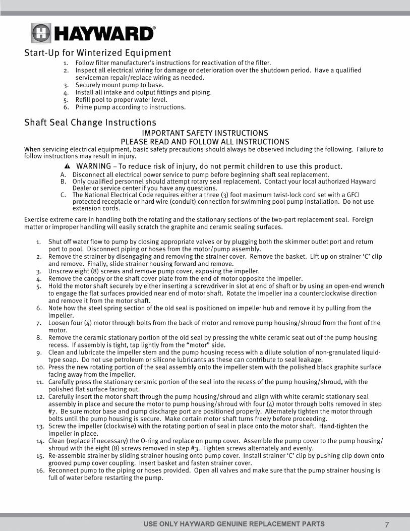
Start-Up for Winterized Equipment 1. Follow filter manufacturer's instructions for reactivation of the filter. 2. Inspect all electrical wiring for damage or deterioration over the shutdown period. Have a qualified
serviceman repair/replace wiring as needed. 3. Securely mount pump to base. 4. Install all intake and output fittings and piping. 5. Refill pool to proper water level. 6. Prime pump according to instructions.
Shaft Seal Change Instructions IMPORTANT SAFETY INSTRUCTIONS
PLEASE READ AND FOLLOW ALL INSTRUCTIONS When servicing electrical equipment, basic safety precautions should always be observed including the following. Failure to follow instructions may result in injury.
WARNING – To reduce risk of injury, do not permit children to use this product. A. Disconnect all electrical power service to pump before beginning shaft seal replacement. B. Only qualified personnel should attempt rotary seal replacement. Contact your local authorized Hayward
Dealer or service center if you have any questions. C. The National Electrical Code requires either a three (3) foot maximum twist-lock cord set with a GFCI
protected receptacle or hard wire (conduit) connection for swimming pool pump installation. Do not use extension cords.
Exercise extreme care in handling both the rotating and the stationary sections of the two-part replacement seal. Foreign matter or improper handling will easily scratch the graphite and ceramic sealing surfaces.
1. Shut off water flow to pump by closing appropriate valves or by plugging both the skimmer outlet port and return port to pool. Disconnect piping or hoses from the motor/pump assembly.
2. Remove the strainer by disengaging and removing the strainer cover. Remove the basket. Lift up on strainer ‘C’ clip and remove. Finally, slide strainer housing forward and remove.
3. Unscrew eight (8) screws and remove pump cover, exposing the impeller. 4. Remove the canopy or the shaft cover plate from the end of motor opposite the impeller. 5. Hold the motor shaft securely by either inserting a screwdriver in slot at end of shaft or by using an open-end wrench
to engage the flat surfaces provided near end of motor shaft. Rotate the impeller ina a counterclockwise direction and remove it from the motor shaft.
6. Note how the steel spring section of the old seal is positioned on impeller hub and remove it by pulling from the impeller.
7. Loosen four (4) motor through bolts from the back of motor and remove pump housing/shroud from the front of the motor.
8. Remove the ceramic stationary portion of the old seal by pressing the white ceramic seat out of the pump housing recess. If assembly is tight, tap lightly from the “motor” side.
9. Clean and lubricate the impeller stem and the pump housing recess with a dilute solution of non-granulated liquid-type soap. Do not use petroleum or silicone lubricants as these can contribute to seal leakage.
10. Press the new rotating portion of the seal assembly onto the impeller stem with the polished black graphite surface facing away from the impeller.
11. Carefully press the stationary ceramic portion of the seal into the recess of the pump housing/shroud, with the polished flat surface facing out.
12. Carefully insert the motor shaft through the pump housing/shroud and align with white ceramic stationary seal assembly in place and secure the motor to pump housing/shroud with four (4) motor through bolts removed in step #7. Be sure motor base and pump discharge port are positioned properly. Alternately tighten the motor through bolts until the pump housing is secure. Make certain motor shaft turns freely before proceeding.
13. Screw the impeller (clockwise) with the rotating portion of seal in place onto the motor shaft. Hand-tighten the impeller in place.
14. Clean (replace if necessary) the O-ring and replace on pump cover. Assemble the pump cover to the pump housing/ shroud with the eight (8) screws removed in step #3. Tighten screws alternately and evenly.
15. Re-assemble strainer by sliding strainer housing onto pump cover. Install strainer ‘C’ clip by pushing clip down onto grooved pump cover coupling. Insert basket and fasten strainer cover.
16. Reconnect pump to the piping or hoses provided. Open all valves and make sure that the pump strainer housing is full of water before restarting the pump.
USE ONLY HAYWARD GENUINE REPLACEMENT PARTS 8
Troubleshooting Motor Will NOT Start – Check For:
1. Improper or loose wiring connections; open switches or relays; tripped circuit breakers, GFCI’s, or blown fuses. 2. Manually check rotation of motor shaft for free movement and lack of obstruction. (See steps 4 & 5 of “Shaft
Seal Change Instructions” in this manual.) 3. If you have a timer, be certain it is working properly. Bypass it if necessary.
Motor Shuts OFF – Check For: 1. Undersized wiring; loose connections; etc. 2. Low voltage at motor or power drop (frequently caused by undersized wiring or extension cord use). 3. Mechanical binding and electrical overload.
NOTE: Your Hayward pump motor is equipped with an “automatic thermal overload protector.” The motor will automatically shut off if power supply drops before heat damage can build up causing windings to burn out. The “thermal overload protector” will allow the motor to automatically restart once the motor has cooled, provided the power source is again up to proper levels. It will continue to cut On/Off until the problem is corrected. Be sure to correct cause of overheating.
Motor Hums, But Does NOT Start – Check For: 1. Centrifugal switch stuck in OPEN position. 2. Binding of motor shaft.
Pump Won’t Prime 1. Make sure pump/strainer housing is filled with water and the cover O-ring is clean, also be sure it is properly
seated in the cover O-ring groove. Make sure strainer cover is locked firmly in position and lubricated with “Jack’s 327.”
2. Make sure all suction and discharge valves are fully open and not blocked, that pool water level is at proper level, and that skimmer weir is not hung up or binded on skimmer wall.
3. Block off to determine if pump will develop a vacuum. You should have 5”-6” of vacuum at the strainer cover (Only your pool dealer can confirm this with a vacuum gauge). You may be able to check by removing the skimmer basket and holding your hand over the bottom port with skimmer full and pump running. If no suction is felt, check for line blockage.
a. If pump develops a vacuum, check for blocked suction line or dirty strainer basket, an air leak in the suction piping may be the cause.
b. If pump does not develop a vacuum and pump has sufficient “priming water”: i. Re-check strainer housing cover and all threaded connections for suction leaks. Check if all
hose clamps are tight. ii. Check voltage to ensure that the motor is rotating at full RPM’s.
iii. Open housing cover and check for clogging or obstruction in suction. Check impeller for debris. iv. Remove and replace shaft seal only if it is leaking.
Low Flow – Generally, Check For: 1. Clogged or restricted strainer or suction line; undersized pool piping. 2. Plugged or restricted discharge line of filter, valve partially closed (high gauge reading).
How to correct: Sand filters – backwash as per manufacturer’s instructions; D.E. filters – backwash as per manufacturer’s instructions; Cartridge filters – clean or replace cartridge.
3. Air leak in suction (bubbles issuing from return fittings). Re-tighten using Teflon tape. 4. Plugged or restricted impeller or impeller sheared off. Replace including new seal assembly.
USE ONLY HAYWARD GENUINE REPLACEMENT PARTS 9
Noisy Pump – Check For: 1. Air leak in suction piping causing rumbling in pump. 2. Cavitation due to restricted or undersized suction line or leak at any joint, low water level in pool, and
unrestricted discharge return lines. Correct suction condition or throttle return lines, if practical. Holding hand over return fitting will sometimes prove this point or putting in a smaller eyeball fitting.
3. Vibration due to improper mounting, etc. Put a rubber pad under metal mounting feet. 4. Foreign matter in pump housing. Loose stones/debris hitting impeller could be cause, remove any of the above. 5. Motor bearings noisy from normal wear, rust, overheating, or concentration of chemicals causing seal damage
which will allow chlorinated water to seep into bearings wiping out the grease causing bearing to whine. All seal leaks should be replaced at once.
6. Equipment base vibrating.
Maintenance Clean strainer basket regularly. Do NOT strike basket to clean. Inspect strainer cover gasket regularly and
replace as necessary. Hayward pumps have self-lubricating motor bearings and shaft seals. No lubrication is necessary. Keep motor clean. Insure air vents are free from obstruction. Occasionally, shaft seals must be replaced, due to wear or damage. See “Shaft Seal Change Instructions” in
this manual.
DATE OF INSTALLATION ____________________ INITIAL PRESSURE GAUGE READING (CLEAN FILTER) _______________________ PUMP MODEL ________________ HORSEPOWER _______________________ FILTER MODEL ________________ SERIAL NUMBER _______________________
Motor (for SP1540C) - 40 GPM SPX1540Z1E ---- ---- Motor (for SP1750) - 1/2 HP ---- ---- SPX1500Z1E Motor (for SP1775) - 3/4 HP ---- ---- SPX1510Z1E* Motor (for SP1780) - 1 HP ---- ---- SPX1510Z1XE* Motor (for SP1580) - 1 HP ---- SPX1510Z1XE ---- Motor (for SP1580X15) - 1-1/2 HP ---- SPX1515Z1E ---- Motor (for SW1585X20) - 2 HP ---- SPX1520Z1ESC ---- Motor (for SW1585X25) - 2-1/2 HP ---- SPX1524Z1ESC ----
* To order 2-speed motor, change "1" in suffix of model number to a "2" (i.e. SPX1510Z2E) *All Twist Lock versions for each pump have “TL” at end of part number (i.e. SP1580TL)
USE ONLY HAYWARD GENUINE REPLACEMENT PARTS 11
HAYWARD® Pool Products Limited Warranty To original purchasers of this equipment, Hayward Pool Products, Inc. warrants its products to be free from defects in materials and workmanship for a period of ONE (1) year from the date of purchase, when used in single family residential applications. The limited warranty excludes damage from freezing, negligence, improper installation, improper use or care or any Acts of God. Parts that fail or become defective during the warranty period shall be repaired or replaced, at our option, within 90 days of the receipt of defective product, barring unforeseen delays, without charge. Proof of purchase is required for warranty service. In the event proof of purchase is not available, the manufacturing date of the product will be the sole determination of the purchase date. To obtain warranty service, please contact the place of purchase or the nearest Hayward Authorized Service Center. For assistance on your nearest Hayward Authorized Service Center please visit us at www.haywardpool.com. Hayward shall not be responsible for cartage, removal, repair or installation labor or any other such costs incurred in obtaining warranty replacements or repair. The Hayward Pool products warranty does not apply to components manufactured by others. For such products, the warranty established by the respective manufacturer will apply. The express limited warranty above constitutes the entire warranty of Hayward Pool Products with respect to its’ pool products and is in lieu of all other warranties expressed or implied, including warranties of merchantability or fitness for a particular purpose. In no event shall Hayward Pool products be responsible for any consequential, special or incidental damages of any nature. Some states do not allow a limitation on how long an implied warranty lasts, or the exclusion of incidental or consequential damages, so the above limitation may not apply to you. This warranty gives you specific legal rights, and you may also have other rights, which vary from state to state.
Hayward Pool Products 620 Division Street
*Supersedes all previous publications. Elizabeth, NJ 07207
▲Retain this Warranty Certificate (upper portion) in a safe and convenient location for your records.