68
2012 Service Agent Training

2012
Service Agent Training

Please login to www.applico.co.nz
for more information
Wiring diagrams, Parts lists and SDoCs
Documentation for new models

CLF64IND, BKF20ID, BKF24ID working principle
How the induction works; basic principle and sequence operation
Basic Induction:
Power board supply the voltage to display board(5V and 12V) and it won’t supply DC to Main Control Board;
Half-Bridge Induction
Power board supply the voltage to display board(5V and 12V) and supply 15V to both the left and right main control board for the relays.
Induction

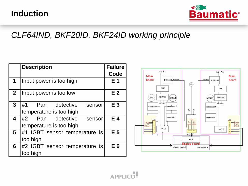
CLF64IND, BKF20ID, BKF24ID working principle
AC is rectified to DC after passing through the EMC line.
The DC voltage is rectified on the coil group by the turning on/off of the IGBT and capacitor charging and discharging. Also, the current is generated by the action of the voltage and then generates the magnetic field.
Induction

CLF64IND, BKF20ID, BKF24ID working principle
Sequence:
1. Directive would be issued by the Display Board to the Chip on the Main control board.
2. The chip will issue a directive to the Main Control Board and then the Main Control Board will start working.
3. At the same time, the Display Board would receive the reactive directive and show the Power stage or other information on the LED display.
Induction

CLF64IND, BKF20ID, BKF24ID working principle
The frequency, voltage and current output from the IGBT transistor from power level 1 to 9 (max.) still cannot currently be provided (confidential).
How to test the if the main control board and display board are faulty if the display board is giving incorrect error code ( ie; an error code is showing faulty main control board and after replacing the main control board the fault still the same).
See the Applico web site for more information on the above
Induction
CLF64IND, BKF20ID, BKF24ID working principle
Induction
Description Failure
Code
1 Input power is too high E 1
2 Input power is too low E 2
3 #1 Pan detective sensor
temperature is too high
E 3
4 #2 Pan detective sensor
temperature is too high
E 4
5 #1 IGBT sensor temperature is
too high
E 5
6 #2 IGBT sensor temperature is
too high
E 6

CLF64IND, BKF20ID, BKF24ID working principle
Induction
Description Failure
Code
1 Fan short circuit F 0
2 Fan open circuit F 1
3 Fan working abnormally F 2
4 #1 Pan detective sensor short
circuit
F 3
5 #1 Pan detective sensor open
circuit
F 4

Please login to www.applico.co.nz
for more information
CLF64IND, BKF20ID, BKF24ID error codes
Induction

CLF64IND, BKF20ID, BKF24ID PTC
Resistance of the thermistor
and temperature sensor
PTC according to the
temperature of the ceramic
glass and the IGBT
transistor. Zero power
Resistance: R25: 100kilo
ohms±5%;
Induction

CLF64IND, BKF20ID, BKF24ID PTC
Induction

CLF64IND, BKF20ID, BKF24ID PTC
Induction

CLF64IND, BKF20ID, BKF24ID working principle
Power supply diagram and
the power output (voltage)
for display board and main
control board.
Power supply diagram is
confidential, sorry that we
cannot provide
Induction

CLF64IND, BKF20ID, BKF24ID power output
Burner 1 and 2
Power level 0 1 2 3 4 5 6 7 8 9
Power Output 0 50 100 200 300 400 1000 1100 1200 1500
Burner 3 and 4
Power Level 0 1 2 3 4 5 6 7 8 9
Power Output 0 50 100 200 300 500 1000 1200 1500 2000
Induction

Generator
Induction

Installation
Induction

Please login to www.applico.co.nz
for more information
More Information
Induction

SI models power output
Induction

SIM62B
2 Multizones 40 x 23 cm
composed of
2 zones x 3 mini inductors of
Ø 10 cm each
Power boosters 4600 W (2 x
2300 W)
4 zones Power
management 4600 + 2600
W : max 7200 W
Induction

SIM91B
Induction

Guangdong Atlan Electronic Applicance Manufacture Co.,Ltd
N
oSample Item
qty/ unit
Supplier
13388C 90CM
GLASS1 PC /
23388C 90CM
GLASS1 PC /
33388C 90CM
GLASS1 PC /
43388C 90CM
GLASS1 PC /
53388C 90CM
GLASS1 PC /
63388C 90CM
GLASS1 PC /
Date:16th,Apr.2012
FAIL
Sample sent by:QA Dept. Tel: Fax:
Hit the glass samples by ball impact machine and observe the form of fragment.
Test Result
PASS
PASS
Photo(Before/After)
Form No:QR-124
Tempered Glass Test
Remark:
Testing method:
Sample description:
Attn: Email:
Item:tempered glass test
Reference No:20120041601
Handler/Date: Review/Date:
Purpose:testing the property of tempered glass
Testing tools:ball impact machine、ruller
All samples are impact resistant
PASS
PASS
FAIL
All glass models: Glass test
Rangehoods

Test qty.
2 pcs
Sample No. Test times Condition
Sample 1 1 fine
Sample 2 1 fine
1000
Standard:GB/T 15763.2-2005
Sample
3388C 90CM GLASS
Height(mm)
Glass for wall-mounted
Test condition:Under normal temperature
Handler/Date: Review/DAte:
Remark:
Description:
Result:
1000
According to test standard, two samples pass the test.
Guangdong Atlan Electronic Appliance Manufacture Co. Ltd Form No:QR-125
Test tool:Impact-resistant test device
Specification/Model
Reference No:20120041603
Impact-resistant Test Report
Date:16th Apr.2012
Sample sent by:QA Dept. Tel:
Attn: Email: Fax:
Subject:Glass Impact-resistant test
Purpose:Testing the impact tolerance of tempered glass
Before After
All glass models: Glass test
Rangehoods

Please login to www.applico.co.nz
for more information
Glass Tests
Rangehoods

Please login to www.applico.co.nz
for more information
All since 2011
Service bulletins

CLD60SS wiring diagram
Q: Using the
diagram, what is
the effect of drain
pump failure?
Dishwashers
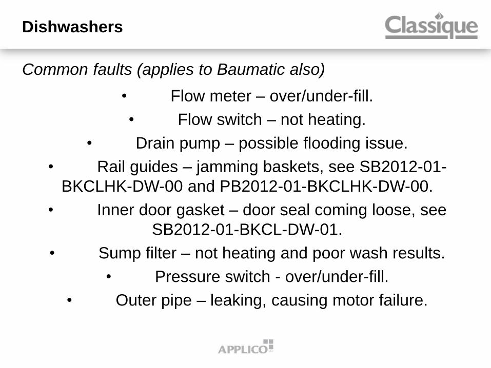
Common faults (applies to Baumatic also)
• Flow meter – over/under-fill.
• Flow switch – not heating.
• Drain pump – possible flooding issue.
• Rail guides – jamming baskets, see SB2012-01-
BKCLHK-DW-00 and PB2012-01-BKCLHK-DW-00.
• Inner door gasket – door seal coming loose, see
SB2012-01-BKCL-DW-01.
• Sump filter – not heating and poor wash results.
• Pressure switch - over/under-fill.
• Outer pipe – leaking, causing motor failure.
Dishwashers

Analysis & correction report
Flow meter = the water is over filling because the flow meter is faulty and once replaced the water level is fine. The vanes of the flow meter are not rotating properly
Door switch = The door lock assy and the door lock hook does not align properly causing the door lock hook engaging above the door lock instead in lock mechanism and the door is impossible to open
Tank Gasket = Not sealing properly and easy to come off
Upper Basket Assy = Even after we sent the bulletin to our service agents on how to fix it, the fault (top rack rollers jamming in slide rails) is continuing after few weeks.
Dishwashers

Please login to www.applico.co.nz
for more information
Analysis & correction report
Dishwashers

Horizontal dishwasher basket: STH905
Modification of the basket extraction handle to avoid the possible interference
with the detergent dispenser thus blocking its opening.
• The glasses supporting grid has been replaced by a plastic tablet box which, at
the detergent dispenser opening, conveys the tablet into the tank.
This aids the tablet melting.
Part no.: 691410618
Dishwashers

Please login to www.applico.co.nz
for more information
STH905: Service Bulletin
Dishwashers

Common faults
• Over filling – caused by timer fault (check pressure
switch operation first).
• Not heating – check wiring to element is correctly
connected.
• Soap dispenser – not opening on horizontal models,
see LVS-SB2010-07.
Dishwashers

DWA and DWAU series
Error code 2 or E2 = Flood switch activated but no visual
water on the base or water leak. After checking the flood
switch and bypassing the micro switch, water level is correct;
showing that pressure switch/flood switch hoses are good
then replace the timer board (faulty).
Dishwashers

SAP399X-8 wiring diagram
Wall ovens

SAP399X-8 wiring diagram
Wall ovens

SAP399X-8 cooling fan and cooling fan resistor
These two parts are critical in the cooling system of the unit. The earlier version did not have the resistor and the cooling fan was controlled directly by the main control board.
If the cooling fan is not working (no fault), check first the resistor resistance, the reading should be between 800 to 820 ohms before replacing the main control board.
In previous Service agent training, we encourage all the service technicians to check all working parts before replacing any electronics card/boards. Still we have an issue that the electronics board short circuit as soon as the main switch turn on because one of the working part is short to earth. The part will not covered under warranty.
Wall ovens

Please login to www.applico.co.nz
for more information
SAP399X: Wiring diagram
Wall ovens
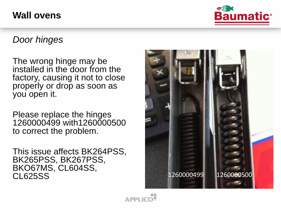
Door hinges
The wrong hinge may be installed in the door from the factory, causing it not to close properly or drop as soon as you open it.
Please replace the hinges 1260000499 with1260000500 to correct the problem.
This issue affects BK264PSS, BK265PSS, BK267PSS, BKO67MS, CL604SS, CL625SS
Wall ovens
1260000499 1260000500

Improved door hinge support
An improved door hinge support has been released for this model to replace those that have become
damaged when the door has been subject to strong forces.
A damaged hinge support can result in the door not closing properly and steam escaping.
This issue affects BK264PSS, BK265PSS, BK267PSS, BK26P5PSS.1, BK26P9PSS, BK650SS, BK660SS, BKO65MS, BKO67MS, BKO6FS, CL604, CL625PSS.1, CL625SS, CL627SS
Wall ovens

Please login to www.applico.co.nz
for more information
HomeKing: All models – Temperature test
Wall Ovens

A1PYID-6
Freestanding ovens

A1PYID-6 wiring diagram
Freestanding ovens

CS19ID-5, CS19ID-6, CE9IMXA induction boards
When replacing a Power Board on units manufactured before
30/08/2007 (serial number below 70830xxxx0), you must replace
both boards AND the communication cable between them.
The inductor coils, interface PCB and display board do not need to
be replaced as they are compatible with the new power board.
NEW PARTS:
3 Plate Induction Generator 813900008
2 Plate Induction Generator 813900009
Communication cable (4 wire) 81291059
If the fault is not identified to be the power board or the display
please take both parts to the job and return the un-needed part for
credit (no re-stocking fee will apply).
Freestanding ovens

CS19ID-6 power board
GB- REPLACE THE OLD
WHITE 2 WIRES CABLE
WITH: THE NEW 4 WIRES
CABLE P/N 821291059
Freestanding ovens

CE9IMXA oven not working
If the oven stops working but the clock is still on, i.e. the
safety cut-out thermostat has not operated, please replace
the power electronic unit. The board is found at the rear
above the cable entry.
Power Electronic Unit 691650760
Freestanding ovens

Please login to www.applico.co.nz
for more information
C9GMN disassembly
Freestanding ovens

Please login to www.applico.co.nz
for more information
C6GMXA8 disassembly
Freestanding ovens

Please login to www.applico.co.nz
for more information
CS19ID-5 & 6/CE9IMXA INDUCTION BOARDS
Freestanding ovens

Printing on knob skirt fading (also applies to Classique)
~ Printing is fading. Don’t
attempt any service. Parts
will be sent directly to the
customer, unless the
customer is incapable of
doing so. Easy for the
customer to do.
Freestanding ovens

Refrigeration
Dave Carrington
Kyzla Inc.
09-238-9948
021-672-828
Contacts

More
For more service agent
contacts, visit
www.applico.co.nz
Contacts

All the information used and
referred to in this presentation
can be found by logging into
www.applico.co.nz, clicking on
the “Bulletins” tab and clicking
the link for “Service Agent
Training 2012”
Applico Service Agent Training 2012

Updated instructions July 2012
APPLICO WEB SITE

Login to www.applico.co.nz If you are using an older browser you will get this message about upgrading to a newer version and which browsers are compatible with our new website

Click on Login
Enter Username and Password To stay logged in tick Remember Login box If unticked you will be automatically logged out after a period of inactivity

Once logged in you should see your name and your account If you have more than one account linked to your login you can change it by clicking on the account name shown
To change account enter name or account number in the search box ( see below ) then click on the account / name you require

To search for a product type the model number into the Search Bar ( see below ) the more accurate the model number the better the search result . If the model is not found then try using less of the model number e.g. BKD62 instead of BKDSS.2
You can turn images on and off with the images button , you can also change the view with the view buttons ( see below )

After searching you should get the model you are after , at times you may also get a selection of models to choose from . If you get “no product found” check your model number is correct After you find the correct model click on the Details tab to get into Product Information

Once you click on Details you will see several tabs Under Downloads you will be able to access Exploded views , User Manuals , SDOC forms and any other documents related to this product Under the parts tab you will see a complete list of parts relating to this model

The image below shows the downloads tab

The image below shows the parts tab To order a part click on the BUY button and the part should then move into your basket NOTE: At present the buy buttons are not functioning and to add a part you can either type the number in manually or click on the part then click buy for that part

If , when you click on the parts tab it looks like the image below press the CTRL key and then while holding CTRL press the minus key This should open up the columns
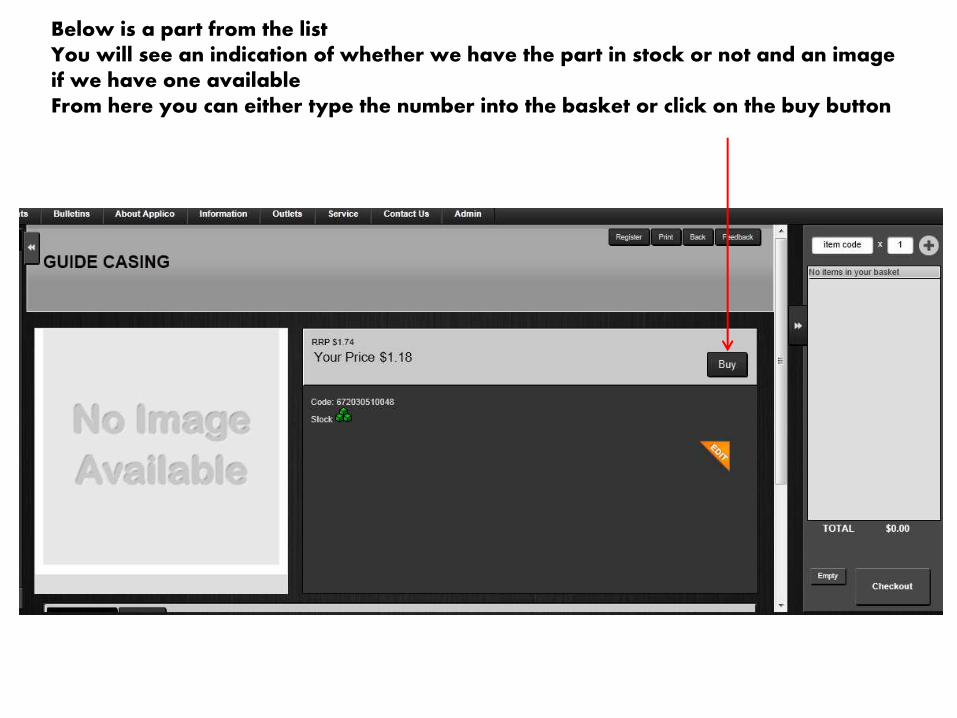
Below is a part from the list You will see an indication of whether we have the part in stock or not and an image if we have one available From here you can either type the number into the basket or click on the buy button

The part should then appear in your basket To remove the part from your basket click on the red X You change the Qty if needed also at this stage by changing the number in the white box under the part description
When you have finished adding parts to your basket click on the Checkout button

Insert your order number , check your address , if the address is incorrect then click on change If all is correct then click on the Purchase button , you can also print off a copy of the order
You can add additional comments in the comments box e.g. if these parts are for a warranty job

When you click on change you will see a selection of address to choose from , whichever one you select will become the default address for future orders
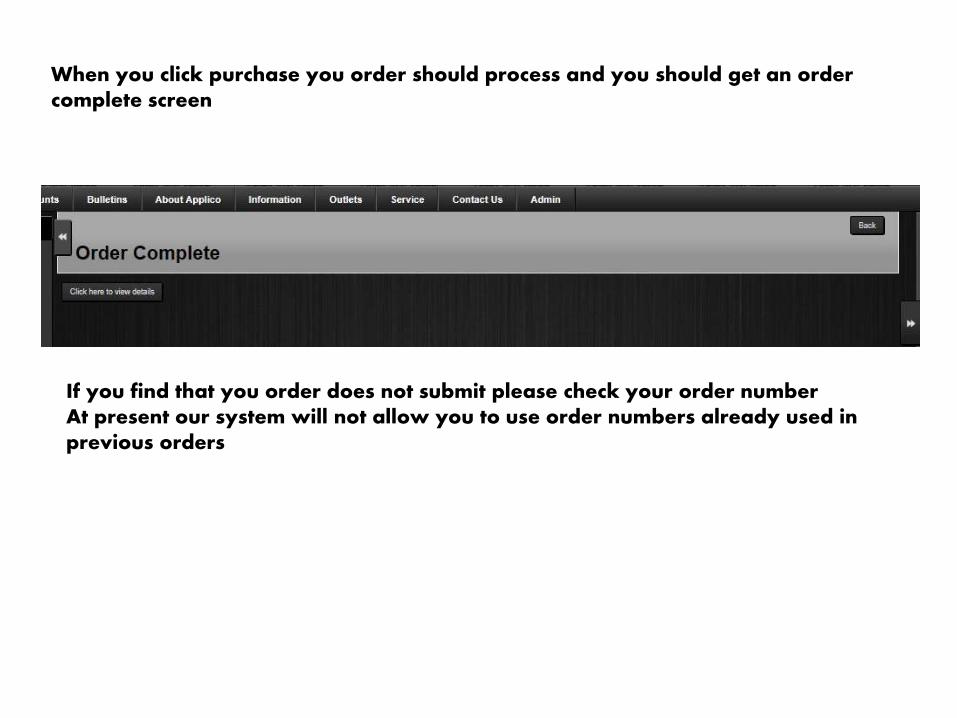
When you click purchase you order should process and you should get an order complete screen
If you find that you order does not submit please check your order number At present our system will not allow you to use order numbers already used in previous orders

Presented by:
Richard Saberon
&
Wayne Edmonds
THANK YOU FOR YOUR
ATTENDANCE


