88 POWERSYNC SYNCHRONOUS MOTORS Pacific Scientific synchronous motors deliver bidirectional motion for low velocity, constant speed motor drives. These motors are driven economically from standard AC line voltage and the synchronous speed is related to the line frequency. Synchronous motor components are identical to those in Pacific Scientific step motors except for high impedance, serially connected stator windings designed for direct operation from AC line voltage. Synchronous motors are often used rather than geared AC induction motors. The desired speed is easily accomplished by gearing up or down from the synchronous speed using a gear box or simple timing belt and pulleys. Agency Approval All NEMA 34 and 42 Frame synchronous motors are UL recognized; Class B motor insulation (File 103510). Typical Application • Automatic antennas • Carousel rotation • Conveyor systems • Dispensing machines • Door openers • Fluid metering • Labeling machines • Packaging machines • Pumps; medical, process and fuel • Sorting machines • Test equipment • Timing belt drives OBJY2 BENEFITS FEATURES With rated torques to 1500 oz-in. Optimized magnetics provide (93.75 lb-in.), 10,5 Nm, maximum performance in a small POWERSYNC provides the envelope, reducing space required highest rated output torque range for the motor. Exceptionally high in the industry torques provide unparalleled application freedom for AC synchronous motors Runs cooler than other Longer, more reliable motor life— AC synchronous motors backed by a two year warranty Rugged “housingless” square frame Efficient use of volume for optimal magnetic design Sealed per NEMA and IP65 For splashproof requirements Outer bearing races won’t turn— Long life bearings— also prevents front locked (in steel insert) and axial shaft movement for encoder rear held by O-ring applications Selection of terminations Match your requirements Special shaft configurations available Easy to apply Simple, economical control components (resistor and capacitor) Precise speed control Synchronous speed for a broad range of applications 72 RPM, 120 Vac, 60 Hz and 240 Vac, For North American use 60 Hz models 60 RPM, 120 Vac, 50 Hz and 240 Vac, For international requirements 50 Hz models Standard NEMA mounting Widely recognized standard Motors (unloaded) reach Fast response for on-off, precisely synchronous speed in as timed events little as 2 milliseconds. Ask us about response time at your load
Transcript
88
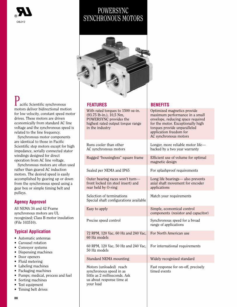
POWERSYNCSYNCHRONOUS MOTORS
Pacific Scientific synchronous
motors deliver bidirectional motion
for low velocity, constant speed motor
drives. These motors are driven
economically from standard AC line
voltage and the synchronous speed is
related to the line frequency.
Synchronous motor components
are identical to those in Pacific
Scientific step motors except for high
impedance, serially connected stator
windings designed for direct
operation from AC line voltage.
Synchronous motors are often used
rather than geared AC induction
motors. The desired speed is easily
accomplished by gearing up or down
from the synchronous speed using a
gear box or simple timing belt and
pulleys.
Agency ApprovalAll NEMA 34 and 42 Frame
synchronous motors are UL
recognized; Class B motor insulation
(File 103510).
Typical Application• Automatic antennas
• Carousel rotation
• Conveyor systems
• Dispensing machines
• Door openers
• Fluid metering
• Labeling machines
• Packaging machines
• Pumps; medical, process and fuel
• Sorting machines
• Test equipment
• Timing belt drives
OBJY2
BENEFITSFEATURESWith rated torques to 1500 oz-in. Optimized magnetics provide (93.75 lb-in.), 10,5 Nm, maximum performance in a small POWERSYNC provides the envelope, reducing space requiredhighest rated output torque range for the motor. Exceptionally high in the industry torques provide unparalleled
application freedom for AC synchronous motors
Runs cooler than other Longer, more reliable motor life—AC synchronous motors backed by a two year warranty
Rugged “housingless” square frame Efficient use of volume for optimal magnetic design
Sealed per NEMA and IP65 For splashproof requirements
Outer bearing races won’t turn— Long life bearings— also prevents front locked (in steel insert) and axial shaft movement for encoder rear held by O-ring applications
Selection of terminations Match your requirementsSpecial shaft configurations available
Easy to apply Simple, economical control components (resistor and capacitor)
Precise speed control Synchronous speed for a broad range of applications
72 RPM, 120 Vac, 60 Hz and 240 Vac, For North American use60 Hz models
60 RPM, 120 Vac, 50 Hz and 240 Vac, For international requirements 50 Hz models
Standard NEMA mounting Widely recognized standard
Motors (unloaded) reach Fast response for on-off, preciselysynchronous speed in as timed eventslittle as 2 milliseconds. Askus about response time at your load
construction only)E=Double ended forencoder (req’d. for allmotors with encoders)S=Special, call factory
Rotor Type
L=Laminated
MountingConfiguration
H=Heavy dutyNEMA
S=Special, callfactory
MODEL NUMBER CODE - NEMA 42 FRAME
Winding/Leads
Y= 3 Leads
HOW TO ORDERReview the Motor Model Number Code to assure that all options are designated. Call your nearest Pacific Scientific MotorProducts Distributor to place orders and for application assistance. If you need to identify your Distributor, call the MotorProducts Division at (815) 226-3100.
RPM/Voltage/Frequency
Y=72 RPM,120V ac, 60Hz
Z=72 RPM, 240V ac, 60Hz
R=60 RPM,120V ac, 50Hz
W=60 RPM, 240V ac, 50Hz
Basic Series
SN=Standard
SN 4 3 H C Y Y - L E K - PD - 01
Number of Rotor Stacks
1=1 Stacks2=2 Stacks3=3 Stacks
The example model number above indicates a standard NEMA 34 frame motor with a three stack rotor. This motor is equippedwith a heavy-duty front end bell and shaft, and a sealed-system rear end bell with MS connectors. It operates at 72 RPM with120V ac, 60 Hz input voltage. It has a three lead winding, a straight keyway and a shaft seal. The encoder specified is 500pprwith line driver output.
The example model number above indicates a standard NEMA 42 frame motor with a three stack rotor. This motor is equippedwith a heavy-duty front end bell and shaft, and a sealed-system rear end bell with MS connectors. It operates at 72 RPM with120V ac, 60 Hz input power. It has a three lead winding, a straight keyway and a shaft seal. The encoder specified is 500pprwith line driver output.
90
INDEX
Product Overview 88
How to use this Section 90
Features & Benefits 88
Selection Overview 91
NEMA 34 Frame MotorsModel Number Code 89
Ratings and Characteristics 92-95
Typical Performance Curves 92-95
Dimensions 96-97
NEMA 42 Frame Motors Model Number Code 89
Ratings and Characteristics 92-95
Typical Performance Curves 92-95
Dimensions 98-99
Motor Technical DataPower Connections 100
Encoder Options 101
Bearing Fatigue Life (L10) 102
Motor Sizing & Selection 103-105
Other Sizing Considerations 106-108
How to use this section• If you’re already familiar with
PULL-OUT Torque Curve The maximum friction load, at a particular inertial load, that can beapplied to the shaft of an AC synchronous motor (running at constant speed) and notcause it to lose synchronism.
RESTART Torque Curve The maximum friction load, at a particular inertial load, that can beapplied to the shaft of an AC synchronous motor without causing it to lose synchronismwhen accelerating to a constant speed from standstill.
An “X” in the Model Number Code indicates an undefined option. See page 89.
Rated Torque and Inertia are maximum values. The rated torque is the combination of loadtorque and friction torque. The motor will accelerate and run at synchronous speed, deliveringthe rated torque value while moving an inertia up to the rated inertia value. Rated inertia is acombination of the load inertia and the motor’s rotor inertia. For assistance in motor selection,see page 103.
Rated Torque and Rated Inertia denote restart conditions with a stiff coupling of .3 arc sec/oz-in. minimum.
Detent torque is the maximum torque that can be applied to an unenergized step motor without causing continuous rotating motion.
Thermal resistance from motor winding to ambient with motor hanging in still air, unmounted.
Small signal inductance as measured with impedance bridge at 1kHz, 1 amp.
Model Number Resistor Resistor Dim. Capacitor Capacitor Dim. Kit Number
(Ohms) (Watts) A B C ( µf ) (rated Vac) Fig. A B C K J
R-C PHASE SHIFT NETWORKSA phase shift network is required and values have been selected to eliminate reversing torque and motor oscillations during motor startup.The network is placed in the circuit as shown in the diagram below. It is important to use the recommended values for the resistor and capacitor which vary with each motor, see p. 108. For your convenience, R-C phase shift network kits are available from Pacific Scientific. The resistors and capacitors are standard and also readily available from electronic component suppliers.
P/M
AC INPUTLINE
CWCCW
C(EXT)
R(EXT) BLACKRED
WHITE
Schematic Diagram All Constructions
B
A
2X MOUNTING BRACKET
C
C ± .06
K± .06
(13,21)(13,20).52 MAX.
(1,52)
(1,524)
(1,524) (1,524)
(1,524)
(1,52)J ± .06
.81 ± .03(20,57 ± 0,76) (20,57 ± 0,76)
C ± .06
.52 MAX.
.81 ± .03
A ± .06
B ± .06
1 1
22
Notes:
All blades are .031 x .250.(0,787 x 6,35)
Foot Brackets.
Resistor Capacitor
2X MOUNTINGBRACKET
FIG. 1 FIG. 2
For 72RPM, 120V ac, 60 Hz
93
POWERSYNC™
Ratings and Characteristics
72 RPM, 240 Vac, 60 Hz
0.00 0.05 0.10 0.15 0.20 0.25
.355 .710 1.07 1.42 1.783.53
3.17
2.82
2.47
2.11
1.76
1.41
1.06
.71
.35
500
450
400
350
300
250
200
150
100
50
Restart torque
Pull-out torque
Rated Torque(See table below)
Rated Inertia(See table below)
Inertia (oz.-in.-s2)
Torq
ue (
oz.-
in.)
Torq
ue (
Nm
)
Inertia (kgm2x10-3)
Safe Operating Area
Typical Performance Curvealso see p.105
PULL-OUT Torque Curve The maximum friction load, at a particular inertial load, that can beapplied to the shaft of an AC synchronous motor (running at constant speed) and notcause it to lose synchronism.
RESTART Torque Curve The maximum friction load, at a particular inertial load, that can beapplied to the shaft of an AC synchronous motor without causing it to lose synchronismwhen accelerating to a constant speed from standstill.
R-C PHASE SHIFT NETWORKSA phase shift network is required and values have been selected to eliminate reversing torque and motor oscillations during motor startup.The network is placed in the circuit as shown in the diagram below. It is important to use the recommended values for the resistor and capacitor which vary with each motor, see p. 108. For your convenience, R-C phase shift network kits are available from Pacific Scientific. The resistors and capacitors are standard and also readily available from electronic component suppliers.
P/M
AC INPUTLINE
CWCCW
C(EXT)
R(EXT) BLACKRED
WHITE
Schematic Diagram All Constructions
B
A
2X MOUNTING BRACKET
C
C ± .06
K± .06
(13,21)(13,20).52 MAX.
(1,52)
(1,524)
(1,524) (1,524)
(1,524)
(1,52)J ± .06
.81 ± .03(20,57 ± 0,76) (20,57 ± 0,76)
C ± .06
.52 MAX.
.81 ± .03
A ± .06
B ± .06
1 1
22
Resistor Capacitor
2X MOUNTINGBRACKET
FIG. 1 FIG. 2
For 72RPM, 240V ac, 60 Hz
An “X” in the Model Number Code indicates an undefined option. See page 89.
Rated Torque and Inertia are maximum values. The rated torque is the combination of loadtorque and friction torque. The motor will accelerate and run at synchronous speed, deliveringthe rated torque value while moving an inertia up to the rated inertia value. Rated inertia is acombination of the load inertia and the motor’s rotor inertia. For assistance in motor selection,see page 103.
Rated Torque and Rated Inertia denote restart conditions with a stiff coupling of .3 arc sec/oz-in. minimum.
Detent torque is the maximum torque that can be applied to an unenergized step motor without causing continuous rotating motion.
Thermal resistance from motor winding to ambient with motor hanging in still air, unmounted.
Small signal inductance as measured with impedance bridge at 1kHz, 1 amp.
Motor has a continuous duty rating if mounted to a 10" x 10" x 1/4" aluminum heat sink in a 40OC ambient.
Motor has an intermittent duty rating unmounted in a 40OC ambient. A maximum duty cycle of 75% is allowed, with a maximum on-time of 150 seconds and zero current during the off-time.
Notes:
All blades are .031 x .250.(0,787 x 6,35)
Foot Brackets.
94
POWERSYNC™
Ratings and Characteristics
60 RPM, 120 Vac, 50 Hz
0.00 0.05 0.10 0.15 0.20 0.25
.355 .710 1.07 1.42 1.783.53
3.17
2.82
2.47
2.11
1.76
1.41
1.06
.71
.35
500
450
400
350
300
250
200
150
100
50
Restart torque
Pull-out torque
Rated Torque(See table below)
Rated Inertia(See table below)
Inertia (oz.-in.-s2)
Torq
ue (
oz.-
in.)
Torq
ue (
Nm
)
Inertia (kgm2x10-3)
Safe Operating Area
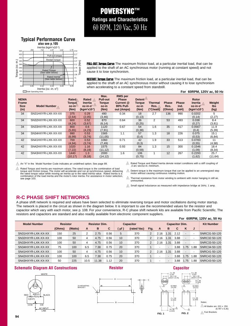
PULL-OUT Torque Curve The maximum friction load, at a particular inertial load, that can beapplied to the shaft of an AC synchronous motor (running at constant speed) and notcause it to lose synchronism.
RESTART Torque Curve The maximum friction load, at a particular inertial load, that can beapplied to the shaft of an AC synchronous motor without causing it to lose synchronismwhen accelerating to a constant speed from standstill.
An “X” in the Model Number Code indicates an undefined option. See page 89.
Rated Torque and Inertia are maximum values. The rated torque is the combination of loadtorque and friction torque. The motor will accelerate and run at synchronous speed, deliveringthe rated torque value while moving an inertia up to the rated inertia value. Rated inertia is acombination of the load inertia and the motor’s rotor inertia. For assistance in motor selection,see page 103.
Rated Torque and Rated Inertia denote restart conditions with a stiff coupling of .3 arc sec/oz-in. minimum.
Detent torque is the maximum torque that can be applied to an unenergized step motor without causing continuous rotating motion.
Thermal resistance from motor winding to ambient with motor hanging in still air, unmounted.
Small signal inductance as measured with impedance bridge at 1kHz, 1 amp.
Model Number Resistor Resistor Dim. Capacitor Capacitor Dim. Kit Number
(Ohms) (Watts) A B C ( µf ) (rated Vac) Fig. A B C K J
R-C PHASE SHIFT NETWORKSA phase shift network is required and values have been selected to eliminate reversing torque and motor oscillations during motor startup.The network is placed in the circuit as shown in the diagram below. It is important to use the recommended values for the resistor and capacitor which vary with each motor, see p. 108. For your convenience, R-C phase shift network kits are available from Pacific Scientific. The resistors and capacitors are standard and also readily available from electronic component suppliers.
P/M
AC INPUTLINE
CWCCW
C(EXT)
R(EXT) BLACKRED
WHITE
Schematic Diagram All Constructions
B
A
2X MOUNTING BRACKET
C
C ± .06
K± .06
(13,21)(13,20).52 MAX.
(1,52)
(1,524)
(1,524) (1,524)
(1,524)
(1,52)J ± .06
.81 ± .03(20,57 ± 0,76) (20,57 ± 0,76)
C ± .06
.52 MAX.
.81 ± .03
A ± .06
B ± .06
1 1
22
Resistor Capacitor
2X MOUNTINGBRACKET
FIG. 1 FIG. 2
For 60RPM, 120V ac, 50 Hz
Typical Performance Curvealso see p.105
Notes:
All blades are .031 x .250.(0,787 x 6,35)
Foot Brackets.
95
POWERSYNC™
Ratings and Characteristics
60 RPM, 240 Vac, 50 Hz
0.00 0.05 0.10 0.15 0.20 0.25
.355 .710 1.07 1.42 1.783.53
3.17
2.82
2.47
2.11
1.76
1.41
1.06
.71
.35
500
450
400
350
300
250
200
150
100
50
Restart torque
Pull-out torque
Rated Torque(See table below)
Rated Inertia(See table below)
Inertia (oz.-in.-s2)
Torq
ue (
oz.-
in.)
Torq
ue (
Nm
)
Inertia (kgm2x10-3)
Safe Operating Area
PULL-OUT Torque Curve The maximum friction load, at a particular inertial load, that can beapplied to the shaft of an AC synchronous motor (running at constant speed) and notcause it to lose synchronism.
RESTART Torque Curve The maximum friction load, at a particular inertial load, that can beapplied to the shaft of an AC synchronous motor without causing it to lose synchronismwhen accelerating to a constant speed from standstill.
An “X” in the Model Number Code indicates an undefined option. See page 89.
Rated Torque and Inertia are maximum values. The rated torque is the combination of loadtorque and friction torque. The motor will accelerate and run at synchronous speed, deliveringthe rated torque value while moving an inertia up to the rated inertia value. Rated inertia is acombination of the load inertia and the motor’s rotor inertia. For assistance in motor selection,see page 103.
Rated Torque and Rated Inertia denote restart conditions with a stiff coupling of .3 arc sec/oz-in. minimum.
Detent torque is the maximum torque that can be applied to an unenergized step motor without causing continuous rotating motion.
Thermal resistance from motor winding to ambient with motor hanging in still air, unmounted.
Small signal inductance as measured with impedance bridge at 1kHz, 1 amp.
Motor has a continuous duty rating if mounted to a 10" x 10" x 1/4" aluminum heat sink in a 40OC ambient.
Motor has an intermittent duty rating unmounted in a 40OC ambient. A maximum duty cycle of 75% is allowed, with a maximum on-time of 150 seconds and zero current during the off-time.
Model Number Resistor Resistor Dim. Capacitor Capacitor Dim. Kit Number
(Ohms) (Watts) A B C ( µf ) (rated Vac) Fig. A B C K J
R-C PHASE SHIFT NETWORKSA phase shift network is required and values have been selected to eliminate reversing torque and motor oscillations during motor startup.The network is placed in the circuit as shown in the diagram below. It is important to use the recommended values for the resistor and capacitor which vary with each motor, see p. 108. For your convenience, R-C phase shift network kits are available from Pacific Scientific. Theresistors and capacitors are standard and also readily available from electronic component suppliers.
P/M
AC INPUTLINE
CWCCW
C(EXT)
R(EXT) BLACKRED
WHITE
Schematic Diagram All Constructions
B
A
2X MOUNTING BRACKET
C
C ± .06
K± .06
(13,21)(13,20).52 MAX.
(1,52)
(1,524)
(1,524) (1,524)
(1,524)
(1,52)J ± .06
.81 ± .03(20,57 ± 0,76) (20,57 ± 0,76)
C ± .06
.52 MAX.
.81 ± .03
A ± .06
B ± .06
1 1
22
Resistor Capacitor
2X MOUNTINGBRACKET
FIG. 1 FIG. 2
For 60RPM, 240V ac, 50 Hz
Typical Performance Curvealso see p.105
Notes:
All blades are .031 x .250.(0,787 x 6,35)
Foot Brackets.
96
DIMENSIONS . . . POWERSYNC™
in. (metric dimensions for ref. only)mm
NEMA 34 FRAME: All motors have a heavy duty NEMA front end bell and large diameter shaft to support the higher output torques
LEADWIRE HOOKUP - ENCODER OPTIONS Model Number Code designation R (Construction/Hookup), p.89
4X Ø .218 THRU
EQUALLY SPACED ONA Ø 3.875 B.C.
.003 (0,077)
-A-.003
(0,077)
Ø D +.0000–.0005
1
K +.0000–.0020
.002(0,051)
3.38
( 85,85)
( )
.06(1,52)
L MAX.
Ø 2.875 ± .002(73,03 ± 0,051)
(2X 45°)
(5,54)
1.25
MOTOR LEADS.875 ± .010(22,3 ± 0,25)
.33(8,38)
+.000–.017T
NOTES:
1 MOTOR LEADS 12.0" MIN.
*See Model Number Code, p 89.
D
31HR
MOTOR*
32HR33HR34HR
.5000 (12,70)(12,70)
(3,175) (14,09) (79,5)(118,1)(156,7)(195,1)
(14,09)(17,91)(17,91)
(3,175)(4,763)(4,763)
(15,875)(15,875)
.1250
K
.555
T
7.686.174.653.13
L MAX.
.5000
.6250
.6250
.1250
.1875
.1875
.555
.705
.705
(98,43)
( - 0,051)
( - 0,432)( - 0,013)
(31,8)
A
A(305)
LEADWIRE HOOKUPDOUBLE SHAFT CONFIGURATIONModel Number Code designation D (Shaft Configuration), p. 89
LEADWIRE HOOKUPFACTORY INSTALLED ENCODERModel Number Code designation E (Encoder Option), p. 89See encoder technical data, p. 101
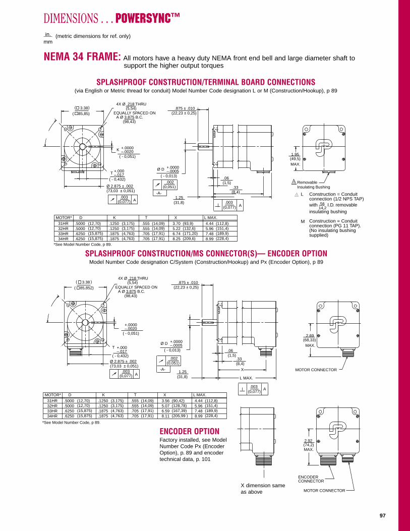
ENCODER OPTIONFactory installed, see ModelNumber Code Px (EncoderOption), p. 89 and encodertechnical data, p. 101
DIMENSIONS . . . POWERSYNC™
in. (metric dimensions for ref. only)mm
NEMA 34 FRAME: All motors have a heavy duty NEMA front end bell and large diameter shaft to support the higher output torques
SPLASHPROOF CONSTRUCTION/TERMINAL BOARD CONNECTIONS(via English or Metric thread for conduit) Model Number Code designation L or M (Construction/Hookup), p 89
SPLASHPROOF CONSTRUCTION/MS CONNECTOR(S)— ENCODER OPTIONModel Number Code designation C/System (Construction/Hookup) and Px (Encoder Option), p 89
*See Model Number Code, p 89.
4X Ø .218 THRU
EQUALLY SPACED ONA Ø 3.875 B.C.
.003 (0,077)
-A-.003
(0,077)
Ø D +.0000–.0005
K +.0000–.0020
.002(0,051)
3.38( 85,85)
( )
.06(1,5)
Ø 2.875 ± .002(73,03 ± 0,051)
(5,54)
1.25
.875 ± .010(22,23 ± 0,25)
.33(8,4)
+.000–.017T
(98,43)
( - 0,051)
( - 0,432)( - 0,013)
(31,8)A
A
D
31HR
MOTOR*
32HR33HR34HR
.5000 (12,70)(12,70)
(3,175) (14,09) (112,8)(151,4)(189,9)(228,4)
(14,09)(17,91)(17,91)
(3,175)(4,763)(4,763)
(15,875)(15,875)
.1250
K
.555
T X
8.997.485.964.44
L MAX.
.5000
.6250
.6250
.1250
.1875
.1875
.555
.705
.705
(93,9)(132,6)(171,20)(209,6)
3.705.226.748.25
Removable Insulating Bushing
1.95(49,5)MAX.
1
Construction = Conduitconnection (1/2 NPS TAP) with .56 I.D. removableinsulating bushing
Construction = Conduitconnection (PG 11 TAP).(No insulating bushingsupplied)
L
M
14,2
L MAX.
X MOTOR CONNECTOR
*See Model Number Code, p 89.
4X Ø .218 THRU
EQUALLY SPACED ONA Ø 3.875 B.C.
.003 (0,077)
-A-.003 (0,077)
Ø D +.0000–.0005
+.0000–.0020
.002(0,051)
3.38( 85,852)
( )
.06(1,5)
Ø 2.875 ± .002(73,03 ± 0,051)
(5,54)
1.25
.875 ± .010(22,23 ± 0,25)
.33(8,4)
+.000–.017
T
(98,43)
( - 0,051)
( - 0,432)( - 0,013)
(31,8)A
A
D
31HR
MOTOR*
32HR33HR34HR
.5000 (12,70)(12,70)
(3,175) (14,09) (112,8)(151,4)(189,9)(228,4)
(14,09)(17,91)(17,91)
(3,175)(4,763)(4,763)
(15,875)(15,875)
.1250
K
.555
T X
8.997.485.964.44
L MAX.
.5000
.6250
.6250
.1250
.1875
.1875
.555
.705
.705
(90,42)(128,78)(167,39)(205,99 )
3.565.076.598.11
2.69(68,33)MAX.
ENCODERCONNECTOR
MOTOR CONNECTOR
2.92(74,2)MAX.
X dimension same as above
98
DIMENSIONS . . . POWERSYNC™ in. (metric dimensions for ref. only)mm
NEMA 42 FRAME: All motors have a heavy duty NEMA front end bell and large diameter shaft to support the higher output torques
LEADWIRE HOOKUP Model Number Code designation R (Construction/Hookup), p. 89
.
+.000–.017
Ø .7500 +.0000–.0005
.1875 +.0000–.0020
.003 (0,077)
.002(0,051)
-A-
.003 (0,077)
1
NOTES:
1 MOTOR LEADS 12.0" MIN.
41HR
MOTOR*
42HR43HR 7.92 (201,2)
5.91 (150,1)3.89 (98,8)
L MAX.
(1,52).06
.48
(2X 45°)
Ø 2.18 ± 0.002(55,52 ± 0,051)
4X Ø .328 THRU(8,33)
EQUALLY SPACED ON AØ 4.950 B.C.
2.19(55,6)
1.375 ± .010(34,93 ± 0,25)
.830
4.325(109,86)( )
L MAX.
MOTOR LEADS
(12,2)
*See Model Number Code, p. 4.
(125,73)
(4,763 - 0,051)
(19,05 - 0,013)
(21,08 - 0,432)
A
A
(304,8)
LEADWIRE HOOKUPDOUBLE SHAFT CONFIGURATIONModel Number Code designation D (Shaft Configuration), p. 89Available on R construction only.
LEADWIRE HOOKUPFACTORY INSTALLED ENCODERModel Number Code designation E (Encoder Option), p. 89See encoder technical data, p. 101
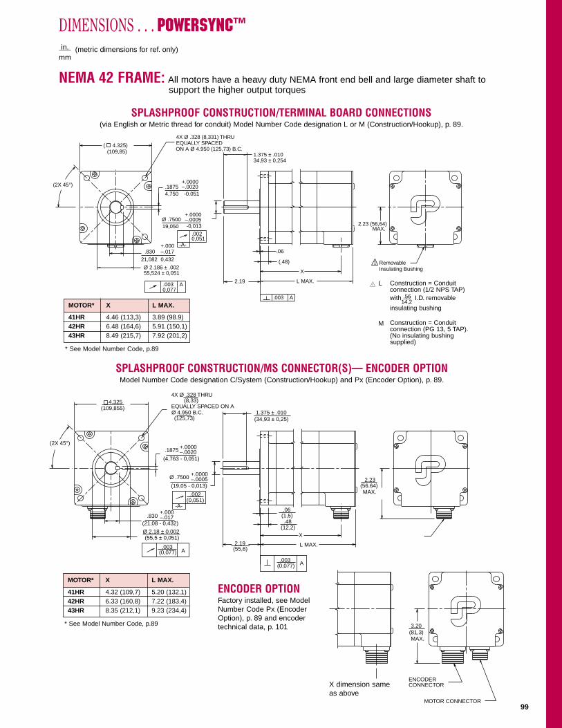
ENCODER OPTIONFactory installed, see ModelNumber Code Px (EncoderOption), p. 89 and encodertechnical data, p. 101
DIMENSIONS . . . POWERSYNC™
in. (metric dimensions for ref. only)mm
NEMA 42 FRAME: All motors have a heavy duty NEMA front end bell and large diameter shaft to support the higher output torques
SPLASHPROOF CONSTRUCTION/TERMINAL BOARD CONNECTIONS(via English or Metric thread for conduit) Model Number Code designation L or M (Construction/Hookup), p. 89.
SPLASHPROOF CONSTRUCTION/MS CONNECTOR(S)— ENCODER OPTIONModel Number Code designation C/System (Construction/Hookup) and Px (Encoder Option), p. 89.
Construction = Conduitconnection (1/2 NPS TAP) with .56 I.D. removable
insulating bushing
Construction = Conduitconnection (PG 13, 5 TAP).(No insulating bushingsupplied)
4X Ø .328 (8,331) THRUEQUALLY SPACED ON A Ø 4.950 (125,73) B.C.
2.19
1.375 ± .01034,93 ± 0,254
.83021,082 0,432
( 4.325)(109,85)
(.48)
X
L MAX.
2.23 (56,64)MAX.
Removable Insulating Bushing
1
-0,013
100
POWERSYNC™
TECHNICAL DATA
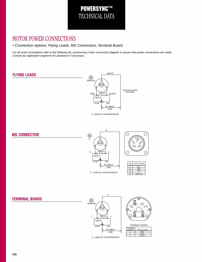
MOTOR POWER CONNECTIONS
FLYING LEADS
MS CONNECTOR
TERMINAL BOARD
• Connection options: Flying Leads, MS Connectors, Terminal Board
For all motor terminations refer to the following AC synchronous motor connection diagram to assure that proper connections are made.Consult our application engineers for assistance if necessary.
P/M
AC INPUTLINE
3 - LEAD AC SYNCHRONOUS
CWCCW
C(EXT)
R(EXT) BLACK
MOTOR LEADS#22 AWG.
RED
GRN/YEL
WHITE
P/ME
AB
CD
AC INPUTLINE
3 - LEAD AC SYNCHRONOUS
CWCCW
C(EXT)
R(EXT) AC
E
B
A BLK B WHT C RED D ------ E GRN/YEL
PIN LEAD COLOR
P/M
AC INPUTLINE
3 - LEAD AC SYNCHRONOUS
TERMINAL BOARDCWCCW
C(EXT)
R(EXT) 31
GRN/YEL
2
63 4
8
7215
1 RED 2 WHT 3 BLACK
TERMINAL NUMBER LEAD COLOR
101
ENCODER OPTIONS…POWERSYNC™NEMA 34 AND NEMA 42 ENCODER OPTIONS
Encoder factory installed (inside).See NEMA 34 drawing, p. 97 andNEMA 42 drawing, p. 99.
PIN FUNCTIONA CHANNEL AB CHANNEL AC CHANNEL BD CHANNEL BE CHANNEL ZF CHANNEL ZG + 5 VDCH 5 VDC RTN
TYPE INCREMENTALENCODER OPTION PH PK PD PF PGPULSES PER REVOLUTION 200 400 500 1000 1024
SUPPLY VOLTAGE +5V ± 10% @ 165 mA MAX.OUTPUT FORMAT DUAL CHANNEL QUADRATURE AND
INDEX W/ COMPLEMENTS
OUTPUT TYPE 23LS31 TTL DIFFERENTIALLINE DRIVER, SHORTCIRCUIT PROTECTED
FREQUENCY RESPONSE 100 kHzROTOR INERTIA (ADDED) 8 x 10⁻⁶ oz-in-s2 for PH, PK and PD
110.4 x 10⁻⁶ oz-in-s2 for PF and PG
PARAMETER LINE DRIVER (Px)
E
G
D
A
F
B
CJH
1
2
9
10
ENCODER OUTPUT
INDEX (Z)
CHANNEL B
ENCODER OUTPUT
FOR CW DIRECTION OF ROTATION WHENVIEWED FROM MOTOR DRIVE SHAFT END.(COMPLEMENTS NOT SHOWN) MIN. EDGESEPARATION 45°. INDEX GATED TO A AND B.
CHANNEL A
NOTE:
NEMA 34, NEMA 42SYSTEM CONSTRUCTION
NEMA 34, REGULARCONSTRUCTION ONLY.
TYPICAL @ 25° C
Encoder factory installed (outside on rearend bell). See NEMA 34 drawing, p. 96 andNEMA 42 drawing, p. 98.
102
SHAFT LOAD AND BEARING FATIGUE LIFE (L10)…POWERSYNC™
The POWERSYNC H-mount configuration has a heavyduty NEMA front end bell and a large diameter shaftto support the higher torque outputs.
Bearings are the only wearing component in an ACsynchronous motor. PacSci uses heavy duty, long lifebearings to assure you the maximum useful life fromevery AC synchronous motor you purchase.
SHAFT LOADINGThe maximum radial fatigue load ratings reflect thefollowing assumptions:
1. Motors are operated at 1 * rated torque2. Fully reversed radial load applied in the center of
the keyway extension3. Infinite life with 99% reliability4. Safety factory = 2
BEARING FATIGUE LIFE (L10) See Model Number Codes on page 4 for clarification.
Note: SPS = Speed, Full Steps Per Second
Motor Max. Max.Radial Force Axial Force
(Lb.) (Lb.)
31, 32 65 305
33, 34 110 305
41 125 404
42, 43 110 404
0
50
100
150
200
250
300
0
50
100
150
200
250
00 20 40 60 80 100
0 20 40 60 80 100 120
0 20 40 60 80 100 1200 20 40 60 80 100 120 140
50
100
150
200
250
1000 SPS
1000 SPS
2500 SPS
2500 SPS
5000 SPS
5000 SPS
10000 SPS
10000 SPS
1000 SPS
1000 SPS
2500 SPS
2500 SPS
5000 SPS
5000 SPS
10000 SPS
10000 SPS
10,000 HOURS BEARING LIFE 10,000 HOURS BEARING LIFE
10,000 HOURS BEARING LIFE 10,000 HOURS BEARING LIFE300
0
50
100
150
200
250
300
350
AXIA
L FO
RCE
(LB)
RADIAL FORCE (LB)
31, 32 MOTORS 33, 34 MOTORS
41 MOTORS 42, 43 MOTORS
RADIAL FORCE (LB)
RADIAL FORCE (LB)
RADIAL FORCE (LB)
AXIA
L FO
RCE
(LB)
AXIA
L FO
RCE
(LB)
AXIA
L FO
RCE
(LB)
Shaft Infinite Life LimitShaft Infinite Life Limit
Shaft Infinite Life LimitShaft Infinite Life Limit
103
POWERSYNC™
MOTOR SIZING & SELECTION
SOLID CYLINDERThe inertia of a solid cylinder can be calculated if either its weight andradius or its density, radius, and length are known. Lead screws,Rotary Tables and Solid Pulley’s can be viewed as solid cylinders whenperforming this calculation.
For known weight and radius: JL = 1 Wr2 = (0.0013)Wr2
2 g
For known density, radius, and length:JL = 1 πlpr4 = (0.0041)lpr4
2 g
where: JL = inertia (oz-in-s2)
W = weight (oz)r = radius (in)l = length (in)p = density of material (oz/in3)g = gravitational constant (386 in/s2)
DIRECT DRIVE LOADFor direct drive loads, the load parameters do not have to bereflected back to the motor shaft since there are no mechanicallinkages involved. The inertia of loads connected directly to themotor shaft can be calculated using the Solid and Hollow Cylinderexamples.
Speed: WM = WL
Torque: TL = T'Inertia: JT = JL + JM
where: WM = motor speed (rpm)WL = load speed (rpm)JT = total system inertia (oz-in-s2)JL = load inertia (oz-in-s2)JM = motor inertia (oz-in-s2)TL = load torque at motor shaft (oz-in)T' = load torque (oz-in)
r
l
Motor
Load
LJLWMW
ir
or
l
Use this procedure to select a motor.
DETERMINE THE LOAD
Three load parameters, defined at the motor shaft, must bedetermined. If there is a mechanical linkage between the load andthe motor shaft, e.g. gears or belts and pulleys, the effect of thesemechanics must be taken into account. The three parameters are:
a. Inertia, J (oz-in-s2, kgm2 x 10-3 ). Inertia is the resistance of an object to change in velocity, i.e., the resistance to accelerate or decelerate. Inertia can be calculated or measured. Inertia is an important parameter since itdefines the torque required to accelerate the load.
b. Friction Torque, TF (oz-in, lb-in., or Nm). This is the torque required to overcome the contact between mechanical components that resists motion of these components relative to each other. Friction torque is independent of speed. It can be calculated but is usually measured using a torque wrench placed at the drive shaft point.
c. Load Torque, TL (oz-in. lb-in., or Nm). This is any torque required by the load and is separate from the friction torque.
MOTION CONTROL MECHANICSTypical mechanical drive systems for motion control can be dividedinto four basic categories; direct drive, gear drive, leadscrew drive,and tangential drive. The following describes each one of thecategories and provides the relevant formulas for calculating thevarious load parameters. In all instances, the formulas reflect allparameters back to the motor shaft. This means that all loadparameters are transformed to the equivalent load parameters “seen”by the motor. Reflecting all parameters back to the motor shaft easesthe calculations necessary to properly size the motor.
CALCULATING THE INERTIA OF A CYLINDERInertia can be seen as the resistance of an object to beingaccelerated or decelerated. In motion control applications, inertia isan important parameter since it is a major part in the definition of thetorque required to accelerate and decelerate the load.
HOLLOW CYLINDERThe inertia of a hollow cylinder can be calculated if its weight, inside radius, and outside radius are known or if its density,inside radius, outside radius, and length are known.
The densities of some commonly used materials are given in the table below
For known weight JL = 1W (or2 + ir2)and radii: 2 g
= (0.0013) (or2 + ir2)W
For known density, JL = πlp (or4 - ir4)radii, and length: 2 g
= (0.0041) (or4-ir4)lp
where: JL = inertia (oz-in-s2)W = weight (oz)or = outside radius (in)ir = inside radius (in)l = length (in)p = density of material (oz/in3)g = gravitational constant (386 in/s2)
104
LEADSCREW DRIVEN LOADFor this type of drive system, the load parameters have to bereflected back to the motor shaft. The inertia of the leadscrew has tobe included and can be calculated using the equations for inertia ofa solid cylinder. For precision positioning applications, the leadscrewis sometimes preloaded to eliminate or reduce backlash. Ifpreloading is used, the preload torque must be included since it canbe a significant term. The leadscrew’s efficiency must also beconsidered in the calculations. The efficiencies of various types ofleadscrews are shown here.
TYPICAL LEADSCREW EFFICIENCIESType Efficiency
Ball-nut 0.90Acme with plastic nut 0.65Acme with metal nut 0.40
Speed: wM = vLp
Torque: TL = 1 FL + 1 FPL x 0.22π pe 2π p
= (0.159)FL/pe + (0.032)FPL/p
Inertia: JT = W 1 2 1 + JLS + JM
g 2πp e
= (6.56 x 10⁻⁵)W/ep2 + JLS + JM
Friction: FF = uW
TF = 1 FF = (0.159)FF/pe2π pe
TANGENTIALLY DRIVEN LOADFor this type of drive system, the load parameters have to bereflected back to the motor shaft. A tangential drive can be a rackand pinion, timing belt and pulley, or chain and sprocket. The inertiaof the pulleys, sprockets, or pinion gears must be included in thecalculations. These inertia’s can be calculated using the equationsshown for the inertia of a Solid or Hollow Cylinder.
Motor
WM
JP1
JP2
V
r
LLoad W
Speed: wM = 1 VL = (0.159)vL/r2π r
Torque: TL = FLr
Inertia: JT = W r2 + JP1 + JP2 + JM
g = (0.0026)Wr2 + JP1 + JP2 + JM
Friction: TF = FFrwhere: wM = motor speed (rpm)
vL = linear load speed (in/min)r = pulley radius (in)
TL = load torque reflected to motor shaft (oz-in)TF = friction torque (oz-in)FL = load force (oz)JT = total system inertia (oz-in-s2)JM = motor inertia (oz-in-s2)JP = pulley inertia(s) (oz-in-s2)W = load weight including belt (oz)FF = frictional force (oz)g = gravitational constant (386 in/s2)
p,e,
Motor
VL
Load W
JLSWM
( )
MOTOR SIZING & SELECTION (CONT.)
Motor
MNJ
W
W
NM
NL
M
L
JL
NL
Load
J
COEFFICIENTS OF FRICTION
Steel on steel 0.580Steel on steel (lubricated) 0.150Teflon on steel 0.040Ball bushing 0.003
For certain applications, the frictional drag torque due topreloading should also be considered as part of the total torquerequirement. Since optimum preloading is one-third of operatingload, it is common practice to use 0.2 as the preload torquecoefficient for the ball screw to obtain a maximum figure forpreload frictional drag torque. At higher than optimumpreloading, the preload frictional drag will add to the torquerequirements, since it is a constant.
GEAR DRIVEN LOADLoad parameters in a gear driven system have to be reflectedback to the motor shaft. The inertia of the gears have to beincluded in the calculations. The gear inertias can be calculatedusing the equations shown for the inertia of a Solid or HollowCylinder.
Speed: wM = wL(NL/NM)Torque: TL = T'(NM/NL)Inertia: JT = (NM/NL)2 (JL + JNL) + JM + JNM
where: wM = motor speed (rpm)wL = load speed (rpm)NM = number of motor gear teethNL = number of load gear teethTL = load torque reflected to motor shaft (oz-in)T' = load torque (oz-in)–not reflectedJT = total system inertia (oz-in-s2)JL = load inertia (oz-in-s2)JM = motor inertia (oz-in-s2)
where: wM = motor speed (rpm)vL = linear load speed (in/min)p = lead screw pitch (revs/in)e = lead screw efficiency
TL = load torque reflected to motor shaft (oz-in)TF = friction torque (oz-in)FL = load force (oz)
FPL = preload force (oz)JT = total system inertia (oz-in-s2)JM = motor inertia (oz-in-s2)JLS = lead screw inertia (oz-in-s2)W = load weight (oz)FF = frictional force (oz)u = coefficient of frictiong = gravitational constant (386 in/s2)
105
POWERSYNC™
MOTOR SIZING & SELECTION
After the load characteristics (torque and inertia) are determined, themotor can be selected. See the ratings and characteristics tablesbeginning on page 92 for reference. The data in the Rated Torque andRated Inertia columns reflect the motors ability to stay in synchronismunder external load conditions not exceeding these values. In theTypical Performance Curve below, the same Rated Torque and RatedInertia values define the motors safe operating area. Once the loadcharacteristics have been determined, proceed as follows:
• Find the ratings and characteristics table that reflects the desired motor on the basis of your synchronous speed (72 or 60 RPM), Voltage (120 or 240V ac) and frequency (60 or 50 Hz). For assistance, see the Selection Overview on page 91.
• In the ratings and characteristics table, find the motor with the Rated Torque and Rated Inertia combination that are slightly above the required torque and inertia load characteristics. This assures that the load characteristics are within the motors safe operating area.
This typical performance curve shows the Pull-out torque, Restart(pull-in) torque, Rated torque and Rated Inertia. These terms aredefined as follows.
• Pull-out torque. The maximum friction load, at a particular inertialload, that can be applied to the shaft of an AC synchronous motor (running at constant speed) and not cause it to lose synchronism.
• Restart (Pull-in) torque. The maximum friction load, at a particular inertial load, that can be applied to the shaft of an AC synchronous motor without causing it to lose synchronism when accelerating to a constant speed from standstill.
• Rated torque. The maximum frictional torque that the motor can accelerate from standstill to synchronous speed.
• Rated inertia. The maximum inertial load the motor can accelerate from standstill to synchronous speed.
0.00 0.05 0.10 0.15 0.20 0.25
.355 .710 1.07 1.42 1.783.53
3.17
2.82
2.47
2.11
1.76
1.41
1.06
.71
.35
500
450
400
350
300
250
200
150
100
50
Restart torque
Pull-out torque
Rated Torque(See table below)
Rated Inertia(See table below)
Inertia (oz.-in.-s2)
Torq
ue (
oz.-
in.)
Torq
ue (
Nm
)
Inertia (kgm2x10-3)
Safe Operating Area
TYPICAL PERFORMANCE CURVE
Curves shown are a NEMA 34, 1 stack motor at 72 RPM, 120 Vac, 60 Hz
106
OTHER SELECTION CONSIDERATIONS… POWERSYNC™
It is worthwhile to review these points to determine if they apply to your particular application.
Temperature The insulation class for POWERSYNC motors is NEMA class B (maximum of 130°C inside the motor).This rating is established by hanging the motor in still air, locking the rotor and energizing the windings.The recommended maximum room temperature is 40°C. If the motor is subjected to 40°C roomtemperature, the motor housing temperature could reach 100°C.
Vibration With all Synchronous Motors, there is some vibration that exists while the motor is running. Thisbecomes less noticeable when the motor is loaded and flexible couplings or belts are used to connectthe load. Vibration insulators can also be used between the motor and the mounting bracket.
Starting A low speed AC synchronous motor is an appropriate solution to a variety of demanding applicationsincluding those which require six or more starts per minute. The motor has no significant current riseon starting and hence no additional heat rise with repeated starts. The motors will start within 1.5cycles of the applied frequency and will reach synchronous speed within 2 to 25 milliseconds at 60 Hz.
The extremely high torque and small frame size of the POWERSYNC motors often lends the motor asa suitable substitute for gearmotors. The advantages include concentric shaft and omission of gearbacklash. Additionally, starting times of gearmotors will be slightly greater due to gearing backlash.
Two or more POWERSYNC motors may be operated simultaneously from the same power source, ifthe total current required by the motors does not exceed the current capacity of the supply. However,since the at rest position of the motors is indeterminant, mechanical synchronization of two or moremotors may never be achieved because of the starting time differential that may exist between motors.
Stalling Low speed motors will not overheat if stalled because starting, full load and no load currents areessentially the same. However, prolonged operation against a solid stop will eventually cause bearingfatigue and probable failure. Stall torque cannot be measured in the conventional manner becausethere is no average torque delivered when the rotor is not in synchronization with the apparent rotationof the stator magnetic field.
Residual Torque When power is removed from the motor, there is some residual torque present. This is called themotor's detent torque and is shown in the catalog ratings table. This torque should not be used forholding a load in situations requiring safety. This parameter is inherent to the motor design and mayvary as much as 50%.
Holding Torque When using an AC synchronous motor on any system with a “potential” type loading, like gravity, it maybe desirable to have the motor hold in a position while waiting to rotate. This can be done by using aDC power supply attached to one or both motor phases. The figure on page 107 shows a typicalconnection diagram.
107
HOLDING TORQUE… POWERSYNC™
Attach a DC power supply across the neutral line and one of the phase wires (there are only 3 wires, Neutral,Phase A and Phase B). Make sure the voltage and current values do not exceed those shown in the table below.These values will provide holding torque approximately 1.15 times the specified pull-out torque rating.
BLACK
RED
OPEN
WHITE
MOTOR
DC SUPPLY
Speed Voltage Freq Holding DC SupplyMotor Torque Voltage
(RPM) (V rms) (Hz) Current (Volts)
SN31HXYY-LXK-XX-XX 72 120 60 0.53 45
108
R-C PHASE SHIFT NETWORK…POWERSYNC™
TYPICAL OPERATION
P/M
AC INPUTLINE
COMMON
3-POSITION SINGLE POLESWITCH
CWCCW
C R
R(EXT) BLACKRED
OFF
WHITE
MOTOR
R-C Network- Resistor and capacitor networks are specific to each motor offering. Reference the datacontained in the data table for values and specifications. Deviations from recommended capacitor or resistorvalues can reduce forward torque and permit the motor to exhibit some of it’s forward torque in the reversemode (vibration). This scenario is less of a problem if the load is substantially frictional. Other values can berecommended by the factory for specific applications. Capacitor and resistor values have been selected toprovide the highest possible torque without sacrificing smooth operation throughout the safe operating area.Capacitor and resistor values may be adjusted by the factory to accommodate specific application needs. Thefigure below shows the connection diagram for AC synchronous motors.
109
CONVERSION TABLESROTARY INERTIA CONVERSION TABLE
TORQUE CONVERSION TABLE(To convert from A to B, multiply by entry in table)
CONVERSION FACTORS
LENGTH
MASS
POWER
TORQUE TO INERTIA RATIO
TORQUE GRADIENT
FORCE
ROTATION
MECHANISM EFFICIENCIES MATERIAL DENSITIES
FRICTION COEFFICIENTS Ffr=µWL
(To convert from A to B, multiply by entry in table)
Steel on Steel ~0.58 Ball Bushings <0.001Steel on Steel (greased) ~0.15 Linear Bearings <0.001Aluminum on Steel ~0.45 Dove-tail Slides ~0.2Copper on Steel ~0.30 Gibb Ways ~0.5Brass on Steel ~0.35Plastic on Steel ~0.15-0.25