PowerTech2.4 L and 3.0 L 4024 and 5030 OEM Diesel Engines OPERATOR’S MANUAL PowerTech2.4 L and 3.0 L OEM Diesel Engines OMRG34851 Issue 20Feb07 (ENGLISH) CALIFORNIA Proposition 65 Warning Diesel engine exhaust and some of its constituents are known to the State of California to cause cancer, birth defects, and other reproductive harm. If this product contains a gasoline engine: WARNING The engine exhaust from this product contains chemicals known to the State of California to cause cancer, birth defects or other reproductive harm. The State of California requires the above two warnings. John Deere Power Systems LITHO IN U.S.A.
Transcript
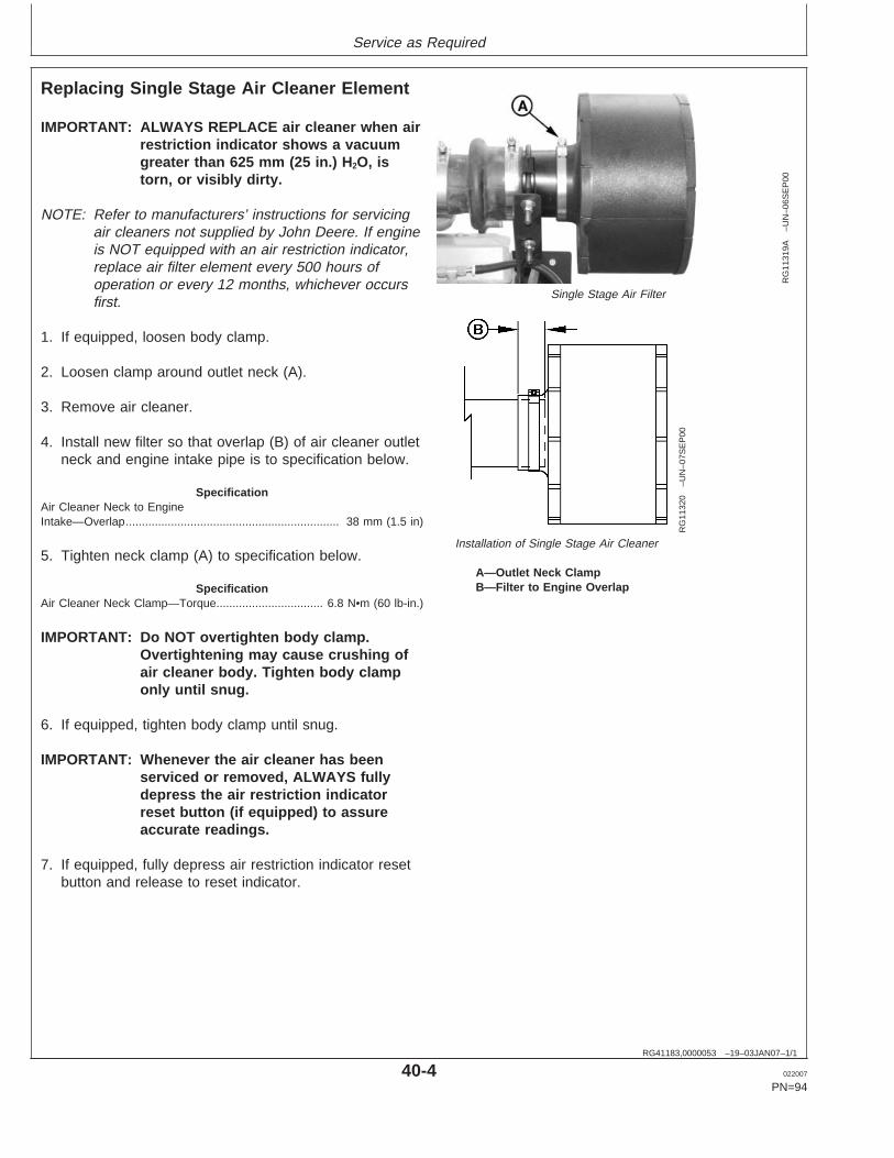
PowerTech2.4 L and 3.0 L4024 and 5030
OEM Diesel Engines
OPERATOR’S MANUALPowerTech 2.4 L and 3.0 L OEM
Diesel Engines
OMRG34851 Issue 20Feb07 (ENGLISH)
CALIFORNIAProposition 65 Warning
Diesel engine exhaust and some of its constituents areknown to the State of California to cause cancer, birth
defects, and other reproductive harm.
If this product contains a gasoline engine:
WARNING
The engine exhaust from this product contains chemicalsknown to the State of California to cause cancer, birth
defects or other reproductive harm.
The State of California requires the above two warnings.
John Deere Power SystemsLITHO IN U.S.A.
Introduction
TX,DH2120 –19–31JAN07–1/1
Forward
READ THIS MANUAL carefully to learn how to operateand service your engine correctly. Failure to do socould result in personal injury or equipment damage.
THIS MANUAL SHOULD BE CONSIDERED apermanent part of your engine and should remain withthe engine when you sell it.
MEASUREMENTS IN THIS MANUAL are given in bothmetric and customary U.S. unit equivalents. Use onlycorrect replacement parts and fasteners. Metric andinch fasteners may require a specific metric or inchwrench.
RIGHT-HAND AND LEFT-HAND sides are determinedby standing at the drive or flywheel end (rear) of theengine and facing toward the front of the engine.
WRITE ENGINE SERIAL NUMBERS and option codesin the spaces indicated in the Record Keeping Section.Accurately record all the numbers. Your dealer also
needs these numbers when you order parts. File theidentification numbers in a secure place off the engine.
SETTING FUEL DELIVERY beyond published factoryspecifications or otherwise overpowering will result inloss of warranty protection for this engine.
CERTAIN ENGINE ACCESSORIES such as radiator,air cleaner, and instruments are optional equipment onJohn Deere OEM Engines. These accessories may beprovided by the equipment manufacturer instead ofJohn Deere. This operator’s manual applies only to theengine and those options available through the JohnDeere distribution network.
NOTE: This operators manual covers only enginesprovided to OEM (Outside EquipmentManufacturers). For engines in Deeremachines, refer to the machine operatorsmanual.
022007
PN=2
Introduction
OURGP11,0000251 –19–27JUL06–1/1
Engine Owner
John Deere Engine Owner:
Don’t wait until you need warranty or other service tomeet your local John Deere Engine Distributor orService Dealer. To register your engine for warrantyvia the Internet, use the following URL:http://www.johndeere.com/enginewarranty
Learn who your dealer is and where he is. At your firstconvenience, go meet him. He’ll want to get to knowyou and to learn what your needs might be.
Aux Utilisateurs De Moteurs John Deere:
N’attendez pas d’etre oblige d’avoir recours a votreconcessionnaire John Deere ou au point de service leplus proche pour vous adresser a lui. Pour enregistrervotre moteur pour la garantie via Internet, utilisezl’adresse suivante:http://www.johndeere.com/enginewarranty
Renseignez-vous des que possible pour l’identifier etle localiser. A la premiere occasion, prenez contactavec lui et faites-vous connaıtre. Il sera lui aussiheureux de faire votre connaissance et de vousproposer ses services le moment venu.
An Den Besitzer Des John Deere Motors:
Warten Sie nicht auf einen evt. Reparaturfall, um dennachstgelegenen John Deere Handler kennen zulernen. Zur Registrierung Ihres Motors fur die Garantiedient folgende Internet-Adresse:http://www.johndeere.com/enginewarranty
Machen Sie sich bei ihm bekannt und nutzen Sie sein“Service Angebot”.
Proprietario del motore John Deere:
Non aspetti fino al momento di far valere la garanzia odi chiedere assistenza per fare la conoscenza del
distributore dei motori John Deere o delconcessionario che fornisce l’assistenza tecnica. Perregistrare via Internet la garanzia del suo motore, sicollegi al seguente sito URL:http://www.johndeere.com/enginewarranty
Lo identifichi e si informi sulla sua ubicazione. Allaprima occasione utile lo contatti. Egli desidera fare lasua conoscenza e capire quali potrebbero essere lesue necessita.
Propietario De Equipo John Deere:
No espere hasta necesitar servicio de garantıa o deotro tipo para conocer a su Distribuidor de MotoresJohn Deere o al Concesionario de Servicio. Registresu motor para la garantıa en la siguiente direccion deinternet: http://www.johndeere.com/enginewarranty
Enterese de quien es, y donde esta situado. Cuandotenga un momento, vaya a visitarlo. A el le gustaraconocerlo, y saber cuales podrıan ser susnecesidades.
Till agare av John Deere motorer:
Ta reda pa vem din aterforsaljare ar och besok honomsa snart tillfalle ges. Vanta inte tills det ar dags forservice eller eventuellt garantiarbete. Din motorgarantiregistrerar Du via Internet pahttp://www.johndeere.com/enginewarranty
Din aterforsaljare vill mycket garna traffa dig for att larakanna dina behov och hur bast han kan hjalpa dig.
All information, illustrations and specifications in this manual are based onthe latest information available at the time of publication. The right isreserved to make changes at any time without notice.
COPYRIGHT 2007DEERE & COMPANY
Moline, IllinoisAll rights reserved
A John Deere ILLUSTRUCTION ManualPrevious Editions
Copyright 2003, 2004
i 022007
PN=1
Contents
Page
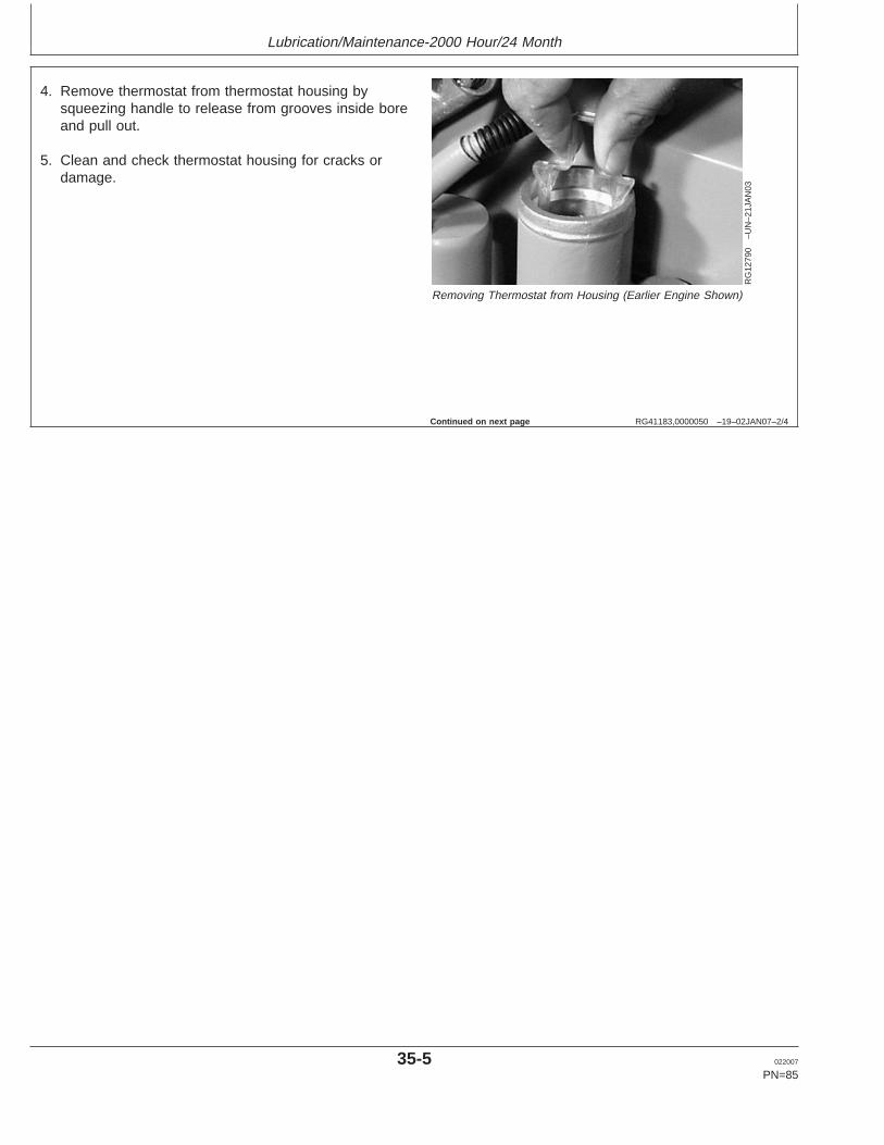
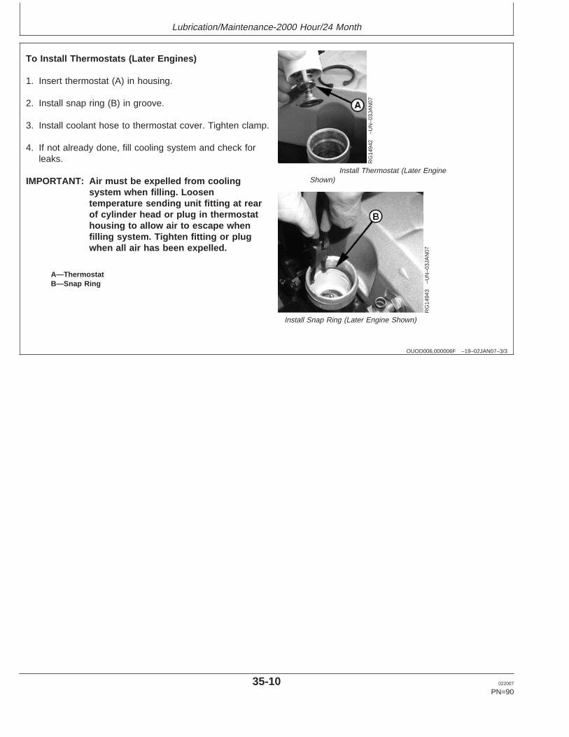
Flushing and Refilling Cooling System . . . . . . . . 35-2Testing Thermostats Opening Temperature-
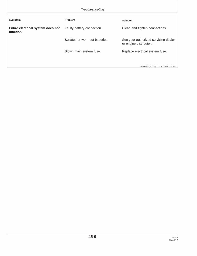
A medallion is located on the rocker arm cover whichidentifies each engine as a John Deere POWERTECHengine.
POWERTECH is a trademark of Deere & Company.
RG41183,0000025 –19–11DEC02–1/1
Engine Serial Number Plate
RG
1268
7–U
N–1
2DE
C02
13-Digit Engine Serial Number Plate
Each engine has a 13-digit John Deere engine serialnumber. The first two digits identify the factory thatproduced the engine.
• “PE” indicates the engine was built in Torreon, Mexico
Your engine’s serial number plate (A) is located on theleft-hand side of cylinder block behind the starter motor.
01-1 022007
PN=7
Record Keeping
OURGP12,0000104 –19–21MAY04–1/1
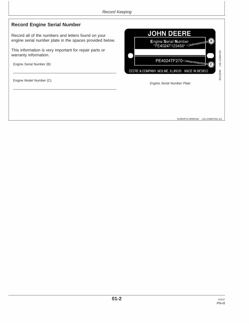
Record Engine Serial Number
RG
1353
9–U
N–2
1MA
Y04
Engine Serial Number Plate
Record all of the numbers and letters found on yourengine serial number plate in the spaces provided below.
This information is very important for repair parts orwarranty information.
Engine Serial Number (B)
Engine Model Number (C)
01-2 022007
PN=8
Record Keeping
RG41183,0000027 –19–11DEC02–1/2
Engine Option Codes
RG
1268
9A–U
N–0
9JU
N04
Engine Option Codes
In addition to the serial number plate, OEM engineshave an engine option code label affixed to the rockerarm cover. These codes indicate which of the engineoptions were installed on your engine at the factory.When in need of parts or service, furnish yourauthorized servicing dealer or engine distributor withthese numbers.
The engine option code label includes an engine basecode (A). This base code must also be recorded alongwith the option codes.
The first two digits of each code identify a specificgroup, such as alternators. The last two digits of eachcode identify one specific option provided on yourengine, such as a 12-volt, 70-amp alternator.
NOTE: These option codes are based on the latestinformation available at the time of publication.The right is reserved to make changes at anytime without notice.
If an engine is ordered without a particular component,the last two digits of that functional group option codewill be 99, 00, or XX. The list on the next page showsonly the first two digits of the code numbers. For futurereference such as ordering repair parts, it is importantto have these code numbers available. To ensure thisavailability, enter the third and fourth digits shown onyour engine option code label in the spaces providedon the following page.
01-3 022007
PN=9
Continued on next page
Record Keeping
RG41183,0000027 –19–11DEC02–2/2
NOTE: Your engine option code label may not containall option codes if an option has been addedafter the engine left the producing factory.
If option code label is lost or destroyed,consult your servicing dealer or enginedistributor selling the engine for a replacement.
An additional option code label may also bedelivered with the engine. Place this sticker ortag, for reference, either on this page or in theengine owner’s warranty booklet underOPTION CODES title.
Option Codes Description Option Codes Description11 Rocker Arm Cover 46 Cylinder Block and Camshaft12 Oil Filler 47 Crankshaft and Bearings13 Crankshaft Pulley 48 Connecting Rods and Pistons14 Flywheel Housing 49 Valve Actuating Mechanism15 Flywheel 50 Oil Pump16 Fuel Injection System 51 Cylinder Head With Valves17 Air Inlet 52 Auxiliary Gear Drive18 Air Cleaner 55 Shipping Stand19 Oil Pan 56 Paint Option20 Coolant Pump 57 Coolant Pump Inlet21 Thermostat Cover 59 Oil Cooler22 Thermostat 60 Alternator Fan Drive Pulley23 Fan Drive 62 Alternator Mounting24 Fan Belt 64 Exhaust Elbow25 Fan 65 Turbocharger26 Engine Coolant Heater 66 Coolant Temperature Switch27 Radiator 67 Speed Sensor28 Exhaust Manifold 68 Crankshaft Rear Damper29 Crankcase Vent System 69 Engine Serial Number Plate30 Starter Motor 74 Air Conditioning (Freon) Compressor31 Alternator 75 Air Restriction Indicator32 Instrument Panel 76 Oil Pressure Switch33 Tachometer 78 Air Compressor35 Fuel Filter 86 Fan Pulley36 Front Plate 87 Belt Tensioner37 Fuel Transfer Pump 88 Oil Filter39 Thermostat Housing 92 Test Certificate40 Oil Dipstick 95 Special Equipment (Factory Installed)43 Starting Aids 97 Special Equipment (Field Installed)44 Timing Gear Cover 98 Lift Straps for Engine45 Balancer Shafts 99 Service Only Parts and Kits
Engine Base Code
01-4 022007
PN=10
Safety
DX,ALERT –19–29SEP98–1/1
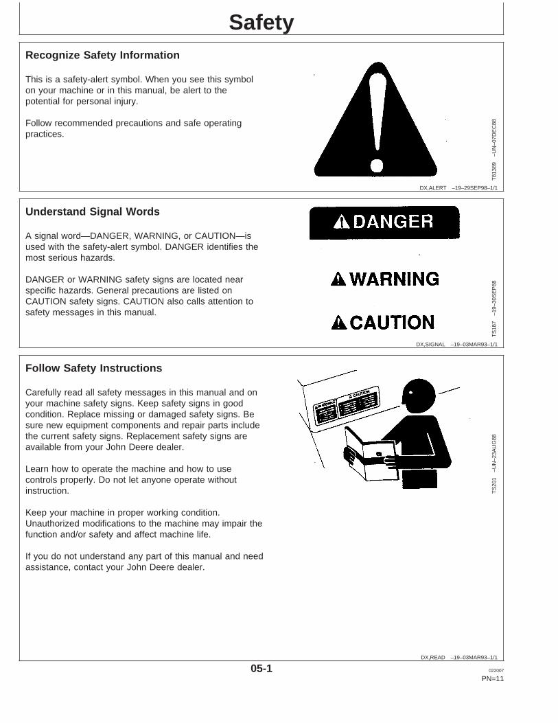
Recognize Safety Information
T81
389
–UN
–07D
EC
88
This is a safety-alert symbol. When you see this symbolon your machine or in this manual, be alert to thepotential for personal injury.
Follow recommended precautions and safe operatingpractices.
DX,SIGNAL –19–03MAR93–1/1
Understand Signal Words
TS
187
–19–
30S
EP
88
A signal word—DANGER, WARNING, or CAUTION—isused with the safety-alert symbol. DANGER identifies themost serious hazards.
DANGER or WARNING safety signs are located nearspecific hazards. General precautions are listed onCAUTION safety signs. CAUTION also calls attention tosafety messages in this manual.
DX,READ –19–03MAR93–1/1
Follow Safety Instructions
TS
201
–UN
–23A
UG
88
Carefully read all safety messages in this manual and onyour machine safety signs. Keep safety signs in goodcondition. Replace missing or damaged safety signs. Besure new equipment components and repair parts includethe current safety signs. Replacement safety signs areavailable from your John Deere dealer.
Learn how to operate the machine and how to usecontrols properly. Do not let anyone operate withoutinstruction.
Keep your machine in proper working condition.Unauthorized modifications to the machine may impair thefunction and/or safety and affect machine life.
If you do not understand any part of this manual and needassistance, contact your John Deere dealer.
05-1 022007
PN=11
Safety
DX,SIGNS1 –19–04JUN90–1/1
Replace Safety Signs
TS
201
–UN
–23A
UG
88
Replace missing or damaged safety signs. See themachine operator’s manual for correct safety signplacement.
DX,LOOSE –19–04JUN90–1/1
Service Machines Safely
TS
228
–UN
–23A
UG
88
Tie long hair behind your head. Do not wear a necktie,scarf, loose clothing, or necklace when you work nearmachine tools or moving parts. If these items were to getcaught, severe injury could result.
Remove rings and other jewelry to prevent electricalshorts and entanglement in moving parts.
DX,WEAR –19–10SEP90–1/1
Wear Protective Clothing
TS
206
–UN
–23A
UG
88
Wear close fitting clothing and safety equipmentappropriate to the job.
Prolonged exposure to loud noise can cause impairmentor loss of hearing.
Wear a suitable hearing protective device such asearmuffs or earplugs to protect against objectionable oruncomfortable loud noises.
Operating equipment safely requires the full attention ofthe operator. Do not wear radio or music headphoneswhile operating machine.
05-2 022007
PN=12
Safety
DX,NOISE –19–03MAR93–1/1
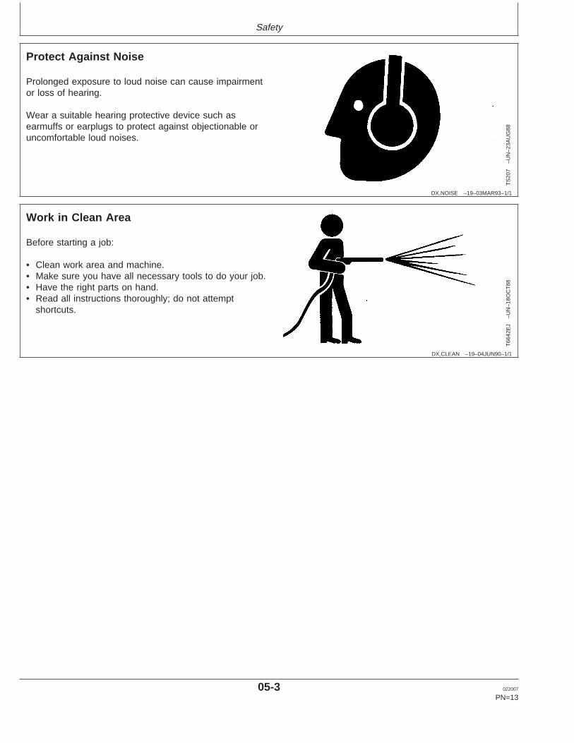
Protect Against Noise
TS
207
–UN
–23A
UG
88
Prolonged exposure to loud noise can cause impairmentor loss of hearing.
Wear a suitable hearing protective device such asearmuffs or earplugs to protect against objectionable oruncomfortable loud noises.
DX,CLEAN –19–04JUN90–1/1
Work in Clean Area
T66
42E
J–U
N–1
8OC
T88
Before starting a job:
• Clean work area and machine.• Make sure you have all necessary tools to do your job.• Have the right parts on hand.• Read all instructions thoroughly; do not attempt
shortcuts.
05-3 022007
PN=13
Safety
DX,SERV –19–17FEB99–1/1
Practice Safe Maintenance
TS
218
–UN
–23A
UG
88
Understand service procedure before doing work. Keeparea clean and dry.
Never lubricate, service, or adjust machine while it ismoving. Keep hands, feet , and clothing frompower-driven parts. Disengage all power and operatecontrols to relieve pressure. Lower equipment to theground. Stop the engine. Remove the key. Allow machineto cool.
Securely support any machine elements that must beraised for service work.
Keep all parts in good condition and properly installed. Fixdamage immediately. Replace worn or broken parts.Remove any buildup of grease, oil, or debris.
On self-propelled equipment, disconnect battery groundcable (-) before making adjustments on electrical systemsor welding on machine.
On towed implements, disconnect wiring harnesses fromtractor before servicing electrical system components orwelding on machine.
DX,LIGHT –19–04JUN90–1/1
Illuminate Work Area Safely
TS
223
–UN
–23A
UG
88
Illuminate your work area adequately but safely. Use aportable safety light for working inside or under themachine. Make sure the bulb is enclosed by a wire cage.The hot filament of an accidentally broken bulb can ignitespilled fuel or oil.
05-4 022007
PN=14
Safety
DX,LIFT –19–04JUN90–1/1
Use Proper Lifting Equipment
TS
226
–UN
–23A
UG
88
Lifting heavy components incorrectly can cause severeinjury or machine damage.
Follow recommended procedure for removal andinstallation of components in the manual.
DX,REPAIR –19–17FEB99–1/1
Use Proper Tools
TS
779
–UN
–08N
OV
89
Use tools appropriate to the work. Makeshift tools andprocedures can create safety hazards.
Use power tools only to loosen threaded parts andfasteners.
For loosening and tightening hardware, use the correctsize tools. DO NOT use U.S. measurement tools onmetric fasteners. Avoid bodily injury caused by slippingwrenches.
Use only service parts meeting John Deere specifications.
DX,SAFE,TOOLS –19–10OCT97–1/1
Construct Dealer-Made Tools Safely
LX10
1674
9–U
N–0
1JU
L97
Faulty or broken tools can result in serious injury. Whenconstructing tools, use proper, quality materials, and goodworkmanship.
Do not weld tools unless you have the proper equipmentand experience to perform the job.
05-5 022007
PN=15
Safety
DX,BYPAS1 –19–29SEP98–1/1
Prevent Machine Runaway
TS
177
–UN
–11J
AN
89
Avoid possible injury or death from machinery runaway.
Do not start engine by shorting across starter terminals.Machine will start in gear if normal circuitry is bypassed.
NEVER start engine while standing on ground. Startengine only from operator’s seat, with transmission inneutral or park.
DX,FIRE2 –19–03MAR93–1/1
Prepare for Emergencies
TS
291
–UN
–23A
UG
88
Be prepared if a fire starts.
Keep a first aid kit and fire extinguisher handy.
Keep emergency numbers for doctors, ambulance service,hospital, and fire department near your telephone.
DX,FIRE1 –19–03MAR93–1/1
Handle Fuel Safely—Avoid Fires
TS
202
–UN
–23A
UG
88
Handle fuel with care: it is highly flammable. Do not refuelthe machine while smoking or when near open flame orsparks.
Always stop engine before refueling machine. Fill fuel tankoutdoors.
Prevent fires by keeping machine clean of accumulatedtrash, grease, and debris. Always clean up spilled fuel.
05-6 022007
PN=16
Safety
OUOD006,0000076 –19–15FEB07–1/1
DO NOT USE Starting Fluids
DO NOT USE any starting fluids with these glow plug -equipped engines as they could cause an extremeexplosion with possible personal injury.
DX,FLAME –19–29SEP98–1/1
Handle Fluids Safely—Avoid Fires
TS
227
–UN
–23A
UG
88
When you work around fuel, do not smoke or work nearheaters or other fire hazards.
Store flammable fluids away from fire hazards. Do notincinerate or puncture pressurized containers.
Make sure machine is clean of trash, grease, and debris.
Do not store oily rags; they can ignite and burnspontaneously.
05-7 022007
PN=17
Safety
DX,MSDS,NA –19–03MAR93–1/1
Handle Chemical Products Safely
TS
1132
–UN
–26N
OV
90
Direct exposure to hazardous chemicals can causeserious injury. Potentially hazardous chemicals used withJohn Deere equipment include such items as lubricants,coolants, paints, and adhesives.
A Material Safety Data Sheet (MSDS) provides specificdetails on chemical products: physical and health hazards,safety procedures, and emergency response techniques.
Check the MSDS before you start any job using ahazardous chemical. That way you will know exactly whatthe risks are and how to do the job safely. Then followprocedures and recommended equipment.
(See your John Deere dealer for MSDS’s on chemicalproducts used with John Deere equipment.)
05-8 022007
PN=18
Safety
DX,WW,CHEM01 –19–05APR04–1/1
Handle Agricultural Chemicals Safely
TS
220
–UN
–23A
UG
88A
3447
1–U
N–1
1OC
T88
Chemicals used in agricultural applications such asfungicides, herbicides, insecticides, pesticides,rodenticides, and fertilizers can be harmful to your healthor the environment if not used carefully.
Always follow all label directions for effective, safe, andlegal use of agricultural chemicals.
Reduce risk of exposure and injury:
• Wear appropriate personal protective equipment asrecommended by the manufacturer. In the absence ofmanufacturer’s instructions, follow these generalguidelines:– Chemicals labeled ’Danger’: Most toxic. Generally
require use of goggles, respirator, gloves, and skinprotection.
– Chemicals labeled ’Warning’: Less toxic. Generallyrequire use of goggles, gloves, and skin protections.
– Chemicals labeled ’Caution’: Least toxic. Generallyrequire use of gloves and skin protection.
• Avoid inhaling spray or dusts.• Always have soap, water, and towel available when
working with chemicals. If chemical contacts skin,hands, or face, wash immediately with soap and water.If chemical gets into eyes, flush immediately with water.
• Wash hands and face after using chemicals and beforeeating, drinking, smoking, or urination.
• Do not smoke or eat while applying chemicals.• After handling chemicals, always bathe or shower and
change clothes. Wash clothing before wearing again.• Seek medical attention immediately if illness occurs
during or shortly after use of chemicals.• Keep chemicals in original containers. Do not transfer
chemicals to unmarked containers or to containers usedfor food or drink.
• Store chemicals in a secure, locked area way fromhuman or livestock food. Keep children away.
• Always dispose of containers properly. Triple rinseempty containers and puncture or crush containers anddispose of properly.
05-9 022007
PN=19
Safety
OUO1004,0000BD8 –19–23JAN07–1/1
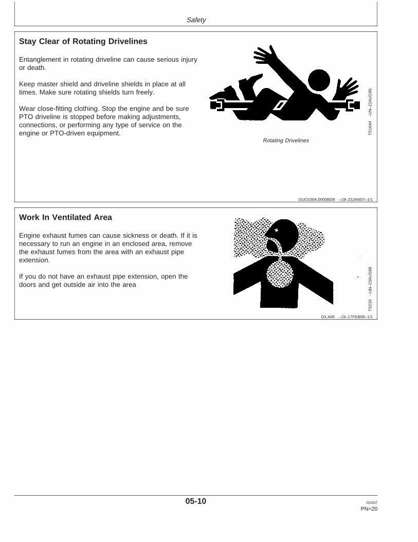
Stay Clear of Rotating Drivelines
TS
1644
–UN
–22A
UG
95
Rotating Drivelines
Entanglement in rotating driveline can cause serious injuryor death.
Keep master shield and driveline shields in place at alltimes. Make sure rotating shields turn freely.
Wear close-fitting clothing. Stop the engine and be surePTO driveline is stopped before making adjustments,connections, or performing any type of service on theengine or PTO-driven equipment.
DX,AIR –19–17FEB99–1/1
Work In Ventilated Area
TS
220
–UN
–23A
UG
88
Engine exhaust fumes can cause sickness or death. If it isnecessary to run an engine in an enclosed area, removethe exhaust fumes from the area with an exhaust pipeextension.
If you do not have an exhaust pipe extension, open thedoors and get outside air into the area
05-10 022007
PN=20
Safety
DX,DUST –19–15MAR91–1/1
Avoid Harmful Asbestos Dust
TS
220
–UN
–23A
UG
88
Avoid breathing dust that may be generated whenhandling components containing asbestos fibers. Inhaledasbestos fibers may cause lung cancer.
Components in products that may contain asbestos fibersare brake pads, brake band and lining assemblies, clutchplates, and some gaskets. The asbestos used in thesecomponents is usually found in a resin or sealed in someway. Normal handling is not hazardous as long asairborne dust containing asbestos is not generated.
Avoid creating dust. Never use compressed air forcleaning. Avoid brushing or grinding material containingasbestos. When servicing, wear an approved respirator. Aspecial vacuum cleaner is recommended to cleanasbestos. If not available, apply a mist of oil or water onthe material containing asbestos.
Keep bystanders away from the area.
DX,FLUID –19–03MAR93–1/1
Avoid High-Pressure Fluids
X98
11–U
N–2
3AU
G88
Escaping fluid under pressure can penetrate the skincausing serious injury.
Avoid the hazard by relieving pressure beforedisconnecting hydraulic or other lines. Tighten allconnections before applying pressure.
Search for leaks with a piece of cardboard. Protect handsand body from high pressure fluids.
If an accident occurs, see a doctor immediately. Any fluidinjected into the skin must be surgically removed within afew hours or gangrene may result. Doctors unfamiliar withthis type of injury should reference a knowledgeablemedical source. Such information is available from Deere& Company Medical Department in Moline, Illinois, U.S.A.
05-11 022007
PN=21
Safety
DX,SPRAY –19–16APR92–1/1
Protect Against High Pressure Spray
TS
1343
–UN
–18M
AR
92
Spray from high pressure nozzles can penetrate the skinand cause serious injury. Keep spray from contactinghands or body.
If an accident occurs, see a doctor immediately. Any highpressure spray injected into the skin must be surgicallyremoved within a few hours or gangrene may result.Doctors unfamiliar with this type of injury should referencea knowledgeable medical source. Such information isavailable from Deere & Company Medical Department inMoline, Illinois, U.S.A.
DX,TORCH –19–10DEC04–1/1
Avoid Heating Near Pressurized Fluid Lines
TS
953
–UN
–15M
AY
90
Flammable spray can be generated by heating nearpressurized fluid lines, resulting in severe burns toyourself and bystanders. Do not heat by welding,soldering, or using a torch near pressurized fluid lines orother flammable materials. Pressurized lines canaccidentally burst when heat goes beyond the immediateflame area.
05-12 022007
PN=22
Safety
DX,PAINT –19–24JUL02–1/1
Remove Paint Before Welding or Heating
TS
220
–UN
–23A
UG
88
Avoid potentially toxic fumes and dust.
Hazardous fumes can be generated when paint is heatedby welding, soldering, or using a torch.
Remove paint before heating:
• Remove paint a minimum of 100 mm (4 in.) from areato be affected by heating. If paint cannot be removed,wear an approved respirator before heating or welding.
• If you sand or grind paint, avoid breathing the dust.Wear an approved respirator.
• If you use solvent or paint stripper, remove stripper withsoap and water before welding. Remove solvent orpaint stripper containers and other flammable materialfrom area. Allow fumes to disperse at least 15 minutesbefore welding or heating.
Do not use a chlorinated solvent in areas where weldingwill take place.
Do all work in an area that is well ventilated to carry toxicfumes and dust away.
Dispose of paint and solvent properly.
DX,RCAP –19–04JUN90–1/1
Service Cooling System Safely
TS
281
–UN
–23A
UG
88
Explosive release of fluids from pressurized coolingsystem can cause serious burns.
Shut off engine. Only remove filler cap when cool enoughto touch with bare hands. Slowly loosen cap to first stopto relieve pressure before removing completely.
05-13 022007
PN=23
Safety
OUOD006,000009D –19–23JAN07–1/1
Install Fan Guards
TS
677
–UN
–21S
EP
89
Rotating Fan
Rotating cooling system fans can cause serious injury.
Keep fan guards in place at all times during engineoperation. Wear close fitting clothes. Stop the engine andbe sure fan is stopped before making adjustments orconnections, or cleaning near the front of the engine.
OURGP12,0000135 –19–11OCT06–1/1
Avoid Hot Parts
TS
271
–UN
–23A
UG
88
Hot Surface
Avoid skin contact with exhaust manifolds, turbochargersand mufflers. Keep flammable materials clear of theturbocharger.
External dry exhaust parts become very hot duringoperation. Turbochargers and exhaust manifolds mayreach temperatures as high as 600°C (1112°F) under fullload. This may ignite paper, cloth or wooden materials.Parts on engines that have been at full load and reducedto no load idle will maintain approximately 150°C (302°F).
DX,SPARKS –19–03MAR93–1/1
Prevent Battery Explosions
TS
204
–UN
–23A
UG
88
Keep sparks, lighted matches, and open flame away fromthe top of battery. Battery gas can explode.
Never check battery charge by placing a metal objectacross the posts. Use a volt-meter or hydrometer.
Do not charge a frozen battery; it may explode. Warmbattery to 16°C (60°F).
05-14 022007
PN=24
Safety
DPSG,OUO1004,2758 –19–23JAN07–1/1
Handling Batteries Safely
TS
204
–UN
–23A
UG
88
Explosion
TS
203
–UN
–23A
UG
88Acid
CAUTION: Battery gas can explode. Keepsparks and flames away from batteries. Use aflashlight to check battery electrolyte level.
Never check battery charge by placing a metalobject across the posts. Use a voltmeter orhydrometer.
Always remove grounded (—) battery clampfirst and replace it last.
CAUTION: Sulfuric acid in battery electrolyte ispoisonous. It is strong enough to burn skin, eatholes in clothing, and cause blindness ifsplashed into eyes.
Avoid the hazard by:
1. Filling batteries in a well-ventilated area.2. Wearing eye protection and rubber gloves.3. Avoiding breathing fumes when electrolyte is
added.4. Avoiding spilling or dripping electrolyte.5. Using proper jump start procedure.
If you spill acid on yourself:
1. Flush your skin with water.2. Apply baking soda or lime to help neutralize
the acid.3. Flush your eyes with water for 15—30
minutes. Get medical attention immediately.
If acid is swallowed:
1. Do not induce vomiting.2. Drink large amounts of water or milk, but do
not exceed 2 L (2 qt.).3. Get medical attention immediately.
WARNING: Battery posts, terminals, and relatedaccessories contain lead and lead compounds, chemicalsknown to the State of California to cause cancer andreproductive harm. Wash hands after handling.
05-15 022007
PN=25
Safety
DX,DRAIN –19–03MAR93–1/1
Dispose of Waste Properly
TS
1133
–UN
–26N
OV
90
Improperly disposing of waste can threaten theenvironment and ecology. Potentially harmful waste usedwith John Deere equipment include such items as oil, fuel,coolant, brake fluid, filters, and batteries.
Use leakproof containers when draining fluids. Do not usefood or beverage containers that may mislead someoneinto drinking from them.
Do not pour waste onto the ground, down a drain, or intoany water source.
Air conditioning refrigerants escaping into the air candamage the Earth’s atmosphere. Government regulationsmay require a certified air conditioning service center torecover and recycle used air conditioning refrigerants.
Inquire on the proper way to recycle or dispose of wastefrom your local environmental or recycling center, or fromyour John Deere dealer.
05-16 022007
PN=26
Fuels, Lubricants, and Coolant
DX,FUEL1 –19–17NOV05–1/1
Diesel Fuel
Consult your local fuel distributor for properties of thediesel fuel available in your area.
In general, diesel fuels are blended to satisfy the lowtemperature requirements of the geographical area inwhich they are marketed.
Diesel fuels specified to EN 590 or ASTM D975 arerecommended.
Required fuel properties
In all cases, the fuel shall meet the followingproperties:
Cetane number of 45 minimum. Cetane numbergreater than 50 is preferred, especially fortemperatures below -20°C (-4°F) or elevations above1500 m (5000 ft).
Cold Filter Plugging Point (CFPP) below theexpected low temperature OR Cloud Point at least5°C (9°F) below the expected low temperature.
Fuel lubricity should pass a minimum level of 3100grams as measured by ASTM D6078 or maximum
scar diameter of 0.45 mm as measured by ASTMD6079 or ISO 12156-1.
Sulfur content:
• Diesel fuel quality and fuel sulfur content mustcomply with all existing emissions regulations for thearea in which the engine operates.
• Use of diesel fuel with sulfur content less than0.10% (1000 ppm) is STRONGLY recommended.
• Use of diesel fuel with sulfur content 0.10% (1000ppm to 0.50% (5000 ppm) may result in REDUCEDoil and filter change intervals.
• BEFORE using diesel fuel with sulfur content greaterthan 0.50% (5000 ppm), contact your John Deeredealer.
• DO NOT use diesel fuel with sulfur content greaterthan 1.0%.
IMPORTANT: Do not mix used diesel engine oil orany other type of lubricating oil withdiesel fuel.
IMPORTANT: Improper fuel additive usage maycause damage on fuel injectionequipment of diesel engines.
DX,FUEL5 –19–27OCT05–1/1
Lubricity of Diesel Fuel
Most diesel fuels manufactured in the United States,Canada, and the European Union have adequatelubricity to ensure proper operation and durability offuel injection system components. However, dieselfuels manufactured in some areas of the world maylack the necessary lubricity.
IMPORTANT: Make sure the diesel fuel used inyour machine demonstrates goodlubricity characteristics.
Fuel lubricity should pass a minimum load level of3100 grams as measured by ASTM D6078 or amaximum scar diameter of 0.45 mm as measured byASTM D6079 or ISO 12156-1.
If fuel of low or unknown lubricity is used, add JohnDeere PREMIUM DIESEL FUEL CONDITIONER (orequivalent) at the specified concentration.
10-1 022007
PN=27
Fuels, Lubricants, and Coolant
DX,FUEL4 –19–19DEC03–1/1
Handling and Storing Diesel Fuel
CAUTION: Handle fuel carefully. Do not fillthe fuel tank when engine is running.
DO NOT smoke while you fill the fuel tank orservice the fuel system.
Fill the fuel tank at the end of each day’s operation toprevent water condensation and freezing during coldweather.
Keep all storage tanks as full as practicable tominimize condensation.
Ensure that all fuel tank caps and covers are installedproperly to prevent moisture from entering.
Monitor water content of the fuel regularly.
When using bio-diesel fuel, the fuel filter may requiremore frequent replacement due to premature plugging.
Check engine oil level daily prior to starting engine. Arising oil level may indicate fuel dilution of the engineoil.
IMPORTANT: The fuel tank is vented through thefiller cap. If a new filler cap isrequired, always replace it with anoriginal vented cap.
When fuel is stored for an extended period or if thereis a slow turnover of fuel, add a fuel conditioner tostabilize the fuel and prevent water condensation.Contact your fuel supplier for recommendations.
DX,FUEL6 –19–14NOV05–1/1
Testing Diesel Fuel
DIESELSCAN is a John Deere fuel analysis programthat can be used to monitor the quality of your fuel. TheDIESELSCAN analysis verifies fuel type, cleanliness,water content, suitability for cold weather operation, andwhether the fuel meets specifications.
Check with your John Deere dealer for availability ofDIESELSCAN kits.
DIESELSCAN is a trademark of Deere & Company
10-2 022007
PN=28
Fuels, Lubricants, and Coolant
DX,FUEL7 –19–14NOV05–1/1
Bio-Diesel Fuel
Consult your local fuel distributor for properties of thebio-diesel fuel available in your area.
Bio-diesel fuels may be used ONLY if the bio-dieselfuel properties meet the latest edition of ASTM D6751,EN 14214, or equivalent specification.
It is recommended to purchase bio-diesel fuel blendedwith B100 from a BQ-9000 Accredited Producer or aBQ-9000 Certified Marketer as recommended by theNational Bio-diesel Board.
The maximum allowable bio-diesel concentration is a5% blend (also known as B5) in petroleum diesel fuel.It has been found that bio-diesel fuels may improvelubricity in concentrations up to this 5% blend.
When using a blend of bio-diesel fuel, the engine oillevel must be checked daily when the air temperatureis –10°C (14°F) or lower. If oil becomes diluted withfuel, shorten oil change intervals accordingly.
IMPORTANT: Raw pressed vegetable oils are NOTacceptable for use as fuel in anyconcentration in John Deereengines.
These oils do not burn completely,and will cause engine failure by
leaving deposits on injectors and inthe combustion chamber.
A major environmental benefit of bio-diesel fuel is itsability to biodegrade. This makes proper storage andhandling of bio-diesel fuel especially important. Areasof concern include:
• Quality of new fuel• Water content of the fuel• Problems due to aging of the fuel
Potential problems resulting from deficiencies in theabove areas when using bio-diesel fuel inconcentrations above 5% may lead to the followingsymptoms:
• Power loss and deterioration of performance• Fuel leakage• Corrosion of fuel injection equipment• Coked and/or blocked injector nozzles, resulting in
engine misfire• Filter plugging• Lacquering and/or seizure of internal components• Sludge and sediments• Reduced service life of engine components
Consult your fuel supplier for additives to improvestorage and performance of bio-diesel fuels.
10-3 022007
PN=29
Fuels, Lubricants, and Coolant
OURGP12,000003F –19–07JUL04–1/1
Aviation (Jet) Fuels
Aviation (jet) fuels may be used with the followingrestrictions.
Type Comments
Jet A Lower viscosity and density than base No. 2-D dieselfuel. Power loss up to 10% can be expected.
Jet A-1 Lower viscosity and density than base No. 2-D dieselfuel. Power loss up to 10% can be expected.
Jet B Not Recommended.Lower density and extremelylow viscosity compared to base No. 2-D diesel fuel.Power loss up to 14% can be expected.
JP-4 Not Recommended.Lower density and extremelylow viscosity compared to base No. 2-D diesel fuel.Power loss up to 12% can be expected.
JP-5 Lower viscosity and density than base No. 2-D dieselfuel. Power loss up to 9% can be expected.
JP-7 Lower viscosity and density than base No. 2-D dieselfuel. Power loss up to 10% can be expected.
JP-8 Lower viscosity and density than base No. 2-D dieselfuel. Power loss up to 10% can be expected.
OURGP12,0000040 –19–07JUL04–1/1
Burner Fuels
Burner fuels, like kerosene, may be used with thefollowing restrictions.
Type Comments
No.2 Higher density and specific gravity than base No. 2-Ddiesel fuel. Power increase up to 3% can beexpected.
No.1 Lower viscosity than base No. 2-D diesel fuel. Powerloss up to 2% can be expected.
10-4 022007
PN=30
Fuels, Lubricants, and Coolant
DX,FUEL10 –19–16DEC05–1/2
Minimizing the Effect of Cold Weather on Diesel Engines
John Deere diesel engines are designed to operateeffectively in cold weather.
However, for effective starting and cold weatheroperation, a little extra care is necessary. Theinformation below outlines steps that can minimize theeffect that cold weather may have on starting andoperation of your engine. See your John Deere dealerfor additional information and local availability of coldweather aids
Use Winter Grade Fuel
When temperatures fall below 5°C (40°F), winter gradefuel (Grade No. 1-D fuel in North America) is bestsuited for cold weather operation. Winter grade fuelhas a lower cloud point and a lower pour point.
Cloud point is the temperature at which wax will beginto form in the fuel and this wax causes fuel filters toplug. Pour point is the temperature at which fuelbegins to thicken and becomes more resistant to flowthrough fuel pumps and lines.
NOTE: On an average, winter grade fuel has a lowerBTU (heat content) rating. Using winter gradefuel may reduce power and fuel efficiency, butshould not cause any other engineperformance effects. Check the grade of fuelbeing used before troubleshooting for lowpower complaints in cold weather operation.
Air Intake Heater
An air intake heater is an available option to aid coldweather starting.
CAUTION: Do not use any starting fluid withan air intake heater.
Starting Fluid
A starting fluid port on the intake is available to aidcold weather starting.
CAUTION: Do not use any starting fluid withan engine equipped with glow plugs
Coolant Heater
An engine block heater (coolant heater) is an availableoption to aid cold weather starting.
Seasonal Viscosity Oil and Proper CoolantConcentration
Use seasonal grade viscosity engine oil based ion theexpected air temperature range between oil changesand proper concentration of low silicate antifreeze asrecommended. (See DIESEL ENGINE OIL andENGINE COOLANT requirements this section.)
Diesel Fuel Flow Additive
Use John Deere Premium Diesel Fuel Conditioner(Winter) or equivalent to treat fuel during the coldweather season. This winter formulation is acombination diesel fuel conditioner and anti-geladditive.
IMPORTANT: Treat fuel when outside temperaturedrops below 0°C (32°F). For bestresults, use with untreated fuel.Follow all recommended instructionson label.
Winterfronts
Use of fabric, cardboard , or solid winterfronts is notrecommended with any John Deere engine. Their usecan result in excessive engine coolant, oil, and chargeair temperatures. This can lead to reduced engine life,loss of power and poor fuel economy. Winterfrontsmay also put abnormal stress on fan and fan drivecomponents potentially causing premature failures.
10-5 022007
PN=31
Continued on next page
Fuels, Lubricants, and Coolant
DX,FUEL10 –19–16DEC05–2/2
If winterfronts are used, they should never totally closeoff the grill frontal area. Approximately 25% area in thecenter of the grill should remain open at all times. Atno time should the air blockage device be applieddirectly to the radiator core.
Radiator Shutters
If equipped with a thermostatically controlled radiatorshutter system, this system should be regulated insuch a way that the shutters are completely open by
the time the coolant reaches 93°C (200°F) to preventexcessive intake manifold temperatures. Manuallycontrolled systems are not recommended.
If air-to-air aftercooling is used, the shutters must becompletely open by the time the intake manifold airtemperature reaches the maximum allowabletemperature out of the charge air cooler.
For more information, see your John Deere dealer.
10-6 022007
PN=32
Fuels, Lubricants, and Coolant
OUOD006,000006C –19–02FEB07–1/1
Diesel Engine Oil
RG
1354
0–U
N–2
1MA
Y04
Air Temperature Ranges
Use oil viscosity based on the expected air temperaturerange during the period between oil changes.
John Deere PLUS-50 oil is preferred.
Oils meeting one of the following specifications are alsorecommended
• ACEA Oil Sequence E4• ACEA Oil Sequence E5• ACEA Oil Sequence E6• ACEA Oil Sequence E7
Extended service intervals may apply when above engineoils are used. Consult the following page.
Other oils may be used if they meet any of the following:
• John Deere TORQ-GARD SUPREME• API Service Category CJ-4• API Service Category CI-4• API Service Category CI-4 Plus• API Service Category CH-4• ACEA Oil Sequence E3
Multi-viscosity diesel engine oils are preferred.
NOTE: DO NOT USE BREAK-IN OILS IN THESEENGINES. These engines are factory-filled withJohn Deere PLUS-50 10W-30, ACEA E4, orACEA E5 oil, and only these oils should be usedto maintain the specified oil level. (Engines maybe shipped dry to comply with certain legislations.)
Diesel fuel quality and fuel sulfur content must complywith all existing emissions regulations for the area inwhich the engine operates.
If diesel fuel with sulfur content greater than 0.5% (5000ppm) is used, reduce the service interval by 50%.
DO NOT use diesel fuel with sulfur content greater than1.0% (10 000 ppm).
PLUS-50 is a trademark of Deere & CompanyTORQ-GARD SUPREME is a trademark of Deere & Company
10-7 022007
PN=33
Fuels, Lubricants, and Coolant
DX,ENOIL6 –19–13SEP06–1/1
Extended Diesel Engine Oil Service Intervals
When John Deere PLUS-50 oil is used with thespecified John Deere filter, the service interval forengine oil and filter changes may be increased by 50%but not to exceed a maxium of 500 hours.
When ACEA E7, ACEA E6, ACEA E5, or ACEA E4oils are used with specified John Deere filter, useengine oil analysis to determine if the service intervalfor engine oil and filter changes may be increased by amaximum of 50% but not to exceed 500 hours.
If John Deere PLUS-50, ACEA E7, ACEA E6, ACEAE5, or ACEA E4 oils are used with other than the
specified John Deere filter, change the engine oil andfilter at the normal service interval.
If John Deere TORQ-GARD SUPREME, API CJ-4,API CI-4 PLUS, API CI-4, API CH-4, or ACEA E3 oilsare used, change the engine oil and filter at the normalservice interval.
If API CG-4, API CF-4, or ACEA E2 oils are used,change the engine oil and filter at 50% of the normalservice interval.
PLUS-50 is a trademark of Deere & CompanyTORQ-GARD SUPREME is a trademark of Deere & Company
DX,LUBMIX –19–18MAR96–1/1
Mixing of Lubricants
In general, avoid mixing different brands or types of oil.Oil manufacturers blend additives in their oils to meetcertain specifications and performance requirements.
Mixing different oils can interfere with the properfunctioning of these additives and degrade lubricantperformance.
Consult your John Deere dealer to obtain specificinformation and recommendations.
DX,FILT –19–18MAR96–1/1
Oil Filters
Filtration of oils is critical to proper operation andlubrication.
Always change filters regularly as specified in this manual.
Use filters meeting John Deere performancespecifications.
10-8 022007
PN=34
Fuels, Lubricants, and Coolant
DX,OILSCAN –19–02DEC02–1/1
OILSCANand COOLSCAN
T68
28A
B–U
N–1
5JU
N89
T68
29A
B–U
N–1
8OC
T88
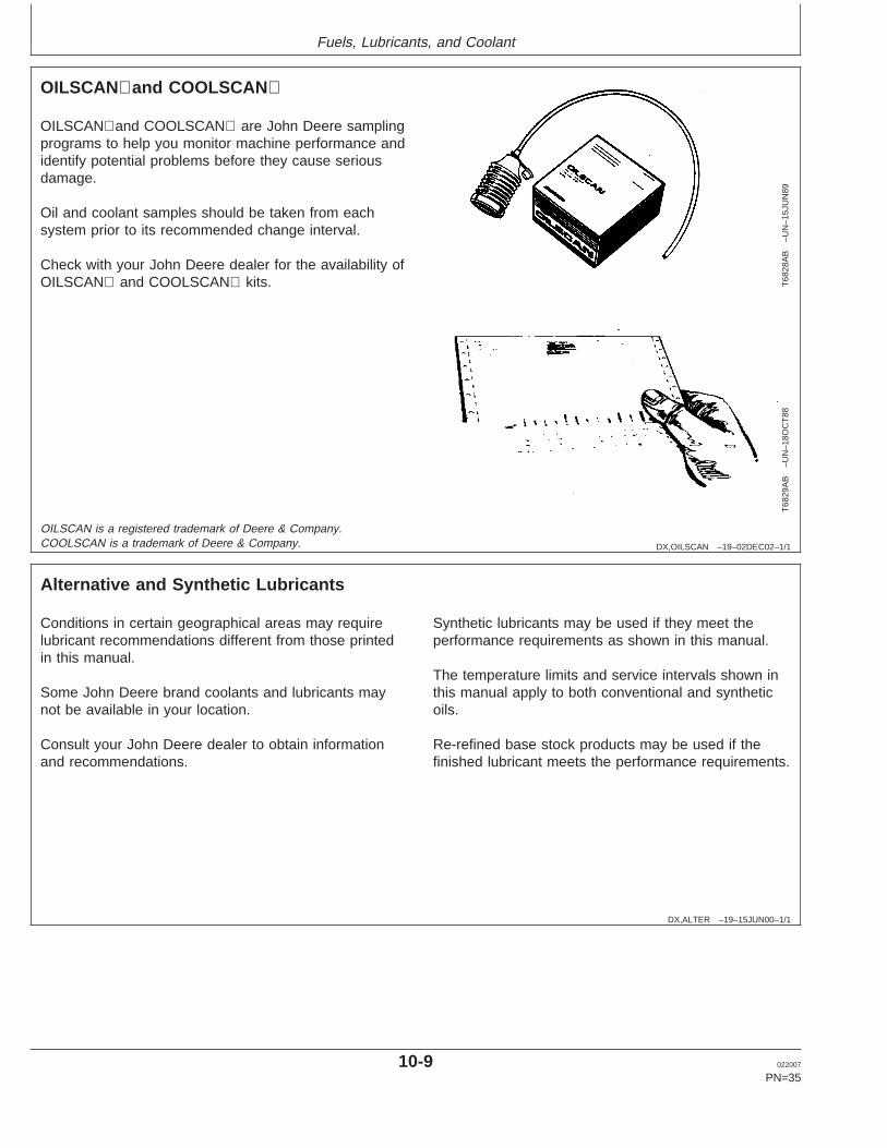
OILSCANand COOLSCAN are John Deere samplingprograms to help you monitor machine performance andidentify potential problems before they cause seriousdamage.
Oil and coolant samples should be taken from eachsystem prior to its recommended change interval.
Check with your John Deere dealer for the availability ofOILSCAN and COOLSCAN kits.
OILSCAN is a registered trademark of Deere & Company.COOLSCAN is a trademark of Deere & Company.
DX,ALTER –19–15JUN00–1/1
Alternative and Synthetic Lubricants
Conditions in certain geographical areas may requirelubricant recommendations different from those printedin this manual.
Some John Deere brand coolants and lubricants maynot be available in your location.
Consult your John Deere dealer to obtain informationand recommendations.
Synthetic lubricants may be used if they meet theperformance requirements as shown in this manual.
The temperature limits and service intervals shown inthis manual apply to both conventional and syntheticoils.
Re-refined base stock products may be used if thefinished lubricant meets the performance requirements.
10-9 022007
PN=35
Fuels, Lubricants, and Coolant
DX,LUBST –19–18MAR96–1/1
Lubricant Storage
Your equipment can operate at top efficiency onlywhen clean lubricants are used.
Use clean containers to handle all lubricants.
Whenever possible, store lubricants and containers inan area protected from dust, moisture, and othercontamination. Store containers on their side to avoidwater and dirt accumulation.
Make certain that all containers are properly marked toidentify their contents.
Properly dispose of all old containers and any residuallubricant they may contain.
DX,GREA1 –19–07NOV03–1/1
Grease
TS
1673
–UN
–31O
CT
03
Use grease based on NLGI consistency numbers and theexpected air temperature range during the service interval.
John Deere SD POLYUREA GREASE is preferred.
The following greases are also recommended
• John Deere HD LITHIUM COMPLEX GREASE• John Deere HD WATER RESISTANT GREASE• John Deere GREASE-GARD
Other greases may be used if they meet the following:
NLGI Performance Classification GC-LB
IMPORTANT: Some types of grease thickeners arenot compatible with others. Consultyour grease supplier before mixingdifferent types of grease
GREASE-GARD is a trademark of Deere & Company
10-10 022007
PN=36
Fuels, Lubricants, and Coolant
DX,COOL3 –19–27OCT05–1/2
Diesel Engine Coolant
The engine cooling system is filled to provideyear-round protection against corrosion and cylinderliner pitting, and winter freeze protection to -37°C(-34°F). If protection at lower temperatures is required,consult your John Deere dealer for recommendations.
John Deere COOL-GARD Prediluted Coolant ispreferred for service.
John Deere COOL-GARD Prediluted Coolant isavailable in a concentration of either 50% ethyleneglycol or 55% propylene glycol.
Additional recommended coolants
The following engine coolant is also recommended:
• John Deere COOL-GARD Coolant Concentrate in a40% to 60% mixture of concentrate with qualitywater.
John Deere COOL-GARD coolants do not require useof supplemental coolant additives, except for periodicreplenishment of additives during the drain interval.
Other fully formulated coolants
Other fully formulated low silicate ethylene orpropylene glycol base coolants for heavy-duty enginesmay be used if they meet one of the followingspecifications:
• ASTM D6210 prediluted (50%) coolant• ASTM D6210 coolant concentrate in a 40% to 60%
mixture of concentrate with quality water
Coolants meeting ASTM D6210 do not require use ofsupplemental coolant additives, except for periodicreplenishment of additives during the drain interval.
Coolants requiring supplemental coolant additives
Other low silicate ethylene glycol base coolants forheavy-duty engines may also be used if they meet oneof the following specifications:
• ASTM D4985 ethylene glycol base prediluted (50%)coolant
• ASTM D4985 ethylene glycol base coolantconcentrate in a 40% to 60% mixture of concentratewith quality water
Coolants meeting ASTM D4985 require an initialcharge of supplemental coolant additives, formulatedfor protection of heavy duty diesel engines againstcorrosion and cylinder liner erosion and pitting. Theyalso require periodic replenishment of additives duringthe drain interval.
Other coolants
It is possible that neither John Deere COOL-GARD norcoolants meeting one of the coolant standards listedabove is available in the geographical area whereservice is performed. If these coolants are unavailable,use a coolant concentrate or prediluted coolant with aquality additive package that provides cylinder linercavitation protection and protects the cooling systemmetals (cast iron, aluminum alloys, and copper alloyssuch as brass) from corrosion.
The additive package must be part of one of thefollowing coolant mixtures:
• ethylene glycol or propylene glycol base prediluted(40% to 60%) coolant
• ethylene glycol or propylene glycol base coolantconcentrate in a 40% to 60% mixture of concentratewith quality water
Water quality
COOL-GARD is a trademark of Deere & Company
10-11 022007
PN=37
Continued on next page
Fuels, Lubricants, and Coolant
DX,COOL3 –19–27OCT05–2/2
Water quality is important to the performance of thecooling system. Distilled, deionized, or demineralizedwater is recommended for mixing with ethylene glycoland propylene glycol base engine coolant concentrate.
IMPORTANT: Do not use cooling system sealingadditives or antifreeze that containssealing additives.
IMPORTANT: Do not mix ethylene glycol andpropylene glycol base coolants.
DX,COOL11 –19–19DEC03–1/1
Drain Intervals for Diesel Engine Coolant
Drain the factory fill engine coolant, flush the coolingsystem, and refill with new coolant after the first 3years or 3000 hours of operation.
Subsequent drain intervals are determined by thecoolant used for service. At each interval, drain thecoolant, flush the cooling system, and refill with newcoolant.
When John Deere COOL-GARD is used, the draininterval may be extended to 5 years or 5000 hours of
operation, provided that the coolant is tested annuallyAND additives are replenished, as needed, by addinga supplemental coolant additive.
If John Deere COOL-GARD is used but the coolant isnot tested OR additives are not replenished by addinga supplemental coolant additive, the drain interval is 3years or 3000 hours of operation
If COOL-GARD is not used, the drain interval isreduced to 2 years or 2000 hours of operation.
COOL-GARD is a trademark of Deere & Company
10-12 022007
PN=38
Fuels, Lubricants, and Coolant
DX,COOL7 –19–19DEC03–1/2
Additional Information About Diesel Engine Coolants and Supplemental CoolantAdditives
Engine coolants are a combination of three chemicalcomponents: ethylene glycol or propylene glycolantifreeze, inhibiting coolant additives, and qualitywater.
Coolant specifications
Some products, including John Deere COOL-GARDPrediluted Coolant, are fully formulated coolants thatcontain all three components in their correctconcentrations. Do not add an initial charge ofsupplemental coolant additives to these fullyformulated products.
Coolants meeting ASTM D6210 do not require aninitial charge of supplemental coolant additives.
Some coolant concentrates, including John DeereCOOL-GARD Coolant Concentrate, contain both glycolantifreeze and inhibiting coolant additives. Mix theseproducts with quality water, but do not add an initialcharge of supplemental coolant additives.
Coolants meeting ASTM D4985 require an initialcharge of supplemental coolant additives.
Replenish coolant additives
The concentration of coolant additives is graduallydepleted during engine operation. Periodicreplenishment of inhibitors is required, even whenJohn Deere COOL-GARD or another fully formulatedcoolant is used. Follow the recommendations in thismanual for the use of supplemental coolant additives.
Why use supplemental coolant additives?
Operating without proper coolant additives will result inincreased corrosion, cylinder liner erosion and pitting,and other damage to the engine and cooling system. A
simple mixture of ethylene glycol or propylene glycoland water will not give adequate protection.
Use of supplemental coolant additives reducescorrosion, erosion, and pitting. These chemicalsreduce the number of vapor bubbles in the coolant andhelp form a protective film on cylinder liner surfaces.This film acts as a barrier against the harmful effectsof collapsing vapor bubbles.
Avoid automotive-type coolants
Never use automotive-type coolants (such as thosemeeting ASTM D3306). These coolants do not containthe correct additives to protect heavy-duty dieselengines. They often contain a high concentration ofsilicates and may damage the engine or coolingsystem.
Water quality
Water quality is important to the performance of thecooling system. Distilled, deionized, or demineralizedwater is recommended for mixing with ethylene glycoland propylene glycol base engine coolant concentrate.All water used in the cooling system should meet thefollowing minimum specifications for quality:
Chlorides <40 mg/L
Sulfates <100 mg/L
Total dissolved solids <340 mg/L
Total hardness <170 mg/L
pH 5.5 to 9.0
Freeze protection
The relative concentrations of glycol and water in theengine coolant determine its freeze protection limit.
COOL-GARD is a trademark of Deere & Company
10-13 022007
PN=39
Continued on next page
Fuels, Lubricants, and Coolant
DX,COOL7 –19–19DEC03–2/2
Ethylene Glycol Freeze Protection Limit
40% -24°C (-12°F)
50% -37°C (-34°F)
60% -52°C (-62°F)
Propylene Glycol Freeze Protection Limit
40% -21°C (-6°F)
50% -33°C (-27°F)
60% -49°C (-56°F)
DO NOT use a coolant-water mixture greater than60% ethylene glycol or 60% propylene glycol.
DX,COOL4 –19–07NOV03–1/1
Supplemental Coolant Additives
The concentration of coolant additives is graduallydepleted during engine operation. For allrecommended coolants, replenish additives betweendrain intervals by adding a supplemental coolantadditive every 12 months or as determined necessaryby coolant testing.
John Deere COOLANT CONDITIONER isrecommended as a supplemental coolant additive inJohn Deere engines.
IMPORTANT: Do not add a supplemental coolantadditive when the cooling system isdrained and refilled with JohnDeereCOOL-GARD.
If other coolants are used, consult the coolant supplierand follow the manufacturer’s recommendation for useof supplemental coolant additives.
The use of non-recommended supplemental coolantadditives may result in additive drop-out and gelationof the coolant.
Add the manufacturer’s recommended concentration ofsupplemental coolant additive. DO NOT add more thanthe recommended amount.
COOL-GARD is a trademark of Deere & Company
10-14 022007
PN=40
Fuels, Lubricants, and Coolant
DX,COOL9 –19–19DEC03–1/1
Testing Diesel Engine Coolant
Testing Diesel Engine Coolant
Maintaining adequate concentrations of glycol andinhibiting additives in the coolant is critical to protectthe engine and cooling system against freezing,corrosion, and cylinder liner erosion and pitting.
Test the coolant solution at intervals of 12 months orless and whenever excessive coolant is lost throughleaks or overheating.
Coolant test strips
Coolant test strips are available from your John Deeredealer. These test strips provide a simple, effective
method to check the freeze point and additive levels ofyour engine coolant.
Compare the results to the supplemental coolantadditive (SCA) chart to determine the amount ofinhibiting additives in your coolant and whether moreJohn Deere COOLANT CONDITIONER should beadded.
COOLSCAN and COOLSCAN PLUS
For a more thorough evaluation of your coolant,perform a COOLSCAN or COOLSCAN PLUS analysis,where available. See your John Deere dealer forinformation.
COOLSCAN is a trademark of Deere & CompanyCOOLSCAN PLUS is a trademark of Deere & Company
DX,COOL6 –19–18MAR96–1/1
Operating in Warm Temperature Climates
John Deere engines are designed to operate usingglycol base engine coolants.
Always use a recommended glycol base enginecoolant, even when operating in geographical areaswhere freeze protection is not required.
IMPORTANT: Water may be used as coolant inemergency situations only.
Foaming, hot surface aluminum andiron corrosion, scaling, andcavitation will occur when water isused as the coolant, even whencoolant conditioners are added.
Drain cooling system and refill withrecommended glycol base enginecoolant as soon as possible.
10-15 022007
PN=41
Fuels, Lubricants, and Coolant
RG,RG34710,7543 –19–09JAN07–1/1
Disposing of Coolant
TS
1133
–UN
–26N
OV
90
Recycle Waste
Improperly disposing of engine coolant can threaten theenvironment and ecology.
Use leakproof containers when draining fluids. Do not usefood or beverage containers that may mislead someoneinto drinking from them.
Do not pour waste onto the ground, down a drain, or intoany water source.
Inquire on the proper way to recycle or dispose of wastefrom your local environmental or recycling center, or fromyour John Deere engine distributor or servicing dealer.
10-16 022007
PN=42
Engine Operating Guidelines
OURGP12,00002AD –19–02JAN07–1/2
Instrument Panel
RG
1336
0–U
N–0
6FE
B04
Instrument Panel and Gauges (Deluxe Version Shown)
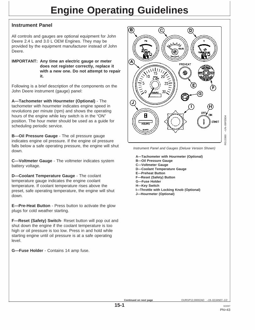
A—Tachometer with Hourmeter (Optional)B—Oil Pressure GaugeC—Voltmeter GaugeD—Coolant Temperature GaugeE—Preheat ButtonF—Reset (Safety) ButtonG—Fuse HolderH—Key SwitchI—Throttle with Locking Knob (Optional)J—Hourmeter (Optional)
All controls and gauges are optional equipment for JohnDeere 2.4 L and 3.0 L OEM Engines. They may beprovided by the equipment manufacturer instead of JohnDeere.
IMPORTANT: Any time an electric gauge or meterdoes not register correctly, replace itwith a new one. Do not attempt to repairit.
Following is a brief description of the components on theJohn Deere instrument (gauge) panel:
A—Tachometer with Hourmeter (Optional) - Thetachometer with hourmeter indicates engine speed inrevolutions per minute (rpm) and shows the operatinghours of the engine while key switch is in the “ON”position. The hour meter should be used as a guide forscheduling periodic service.
B—Oil Pressure Gauge - The oil pressure gaugeindicates engine oil pressure. If the engine oil pressurefalls below a safe operating pressure, the engine will shutdown.
C—Voltmeter Gauge - The voltmeter indicates systembattery voltage.
D—Coolant Temperature Gauge - The coolanttemperature gauge indicates the engine coolanttemperature. If coolant temperature rises above thepreset, safe operating temperature, the engine will shutdown.
E—Pre-Heat Button - Press button to activate the glowplugs for cold weather starting.
F—Reset (Safety) Switch- Reset button will pop out andshut down the engine if the coolant temperature is toohigh or oil pressure is too low. Press in and hold whilestarting engine until oil pressure is at a safe operatinglevel.
G—Fuse Holder - Contains 14 amp fuse.
15-1 022007
PN=43
Continued on next page
Engine Operating Guidelines
OURGP12,00002AD –19–02JAN07–2/2
H—Key Switch - The key switch controls the electricalsystem. Positions of key switch are marked as follows:OFF, ON, and START.
I—Throttle with Locking Knob (Optional) - The throttlecontrol is used to control engine speed. The throttlelocking knob can be used to lock the throttle at a setspeed.
J—Hourmeter (Optional) - The hourmeter indicates theoperating hours of the engine while key switch is in the“ON” position. The hour meter should be used as a guidefor scheduling periodic service.
15-2 022007
PN=44
Engine Operating Guidelines
OURGP12,00002AF –19–02JAN07–1/1
Normal Engine Operation
Before starting, fill engine with oil and coolant meetingspecifications. (See DIESEL ENGINE OIL and DIESELENGINE COOLANT SPECIFICATIONS in Fuels,Lubricants, and Coolant section.)
• Observe engine coolant temperature and engine oilpressure. Temperatures and pressures will varybetween engines and with changing operatingconditions, temperatures, and loads.
• Normal engine oil pressure is 360 ± 105 kPa (52 ± 15psi).
• Normal engine coolant operating temperature range is82° – 94° C (180° – 201° F). If coolant temperaturerises above 105° C (220° F), reduce load on engine.Unless temperature drops quickly, stop engine anddetermine cause before resuming operation.
• Operate the engine under a lighter load and at slowerthan normal speed for first 15 minutes after start-up. DONOT run engine at slow idle.
• Stop engine immediately if there are any signs of partfailure. Symptoms that may be early signs of engineproblems are:– Sudden drop in oil pressure– Abnormal coolant temperatures– Unusual noise or vibration– Sudden loss of power– Excessive black exhaust– Excessive fuel consumption– Excessive oil consumption– Fluid leaks
15-3 022007
PN=45
Engine Operating Guidelines
OUOD006,000006D –19–31JAN07–1/2
Break-In Service
RG
1269
2–U
N–0
7FE
B03
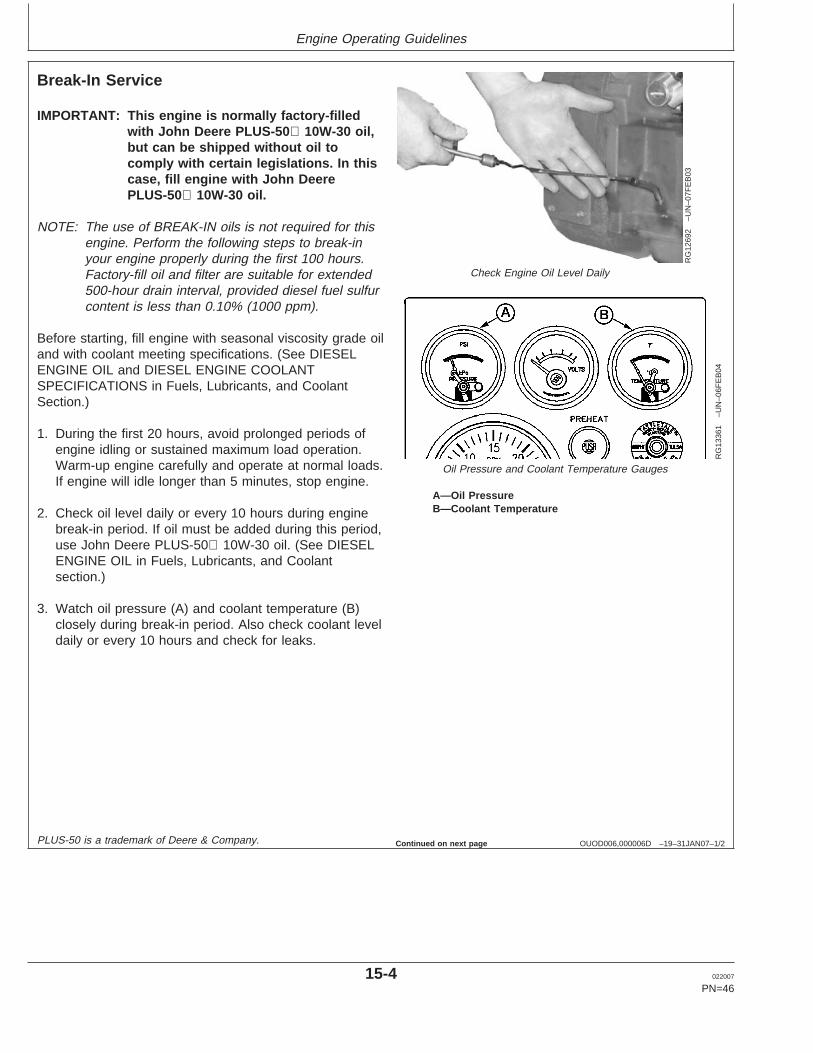
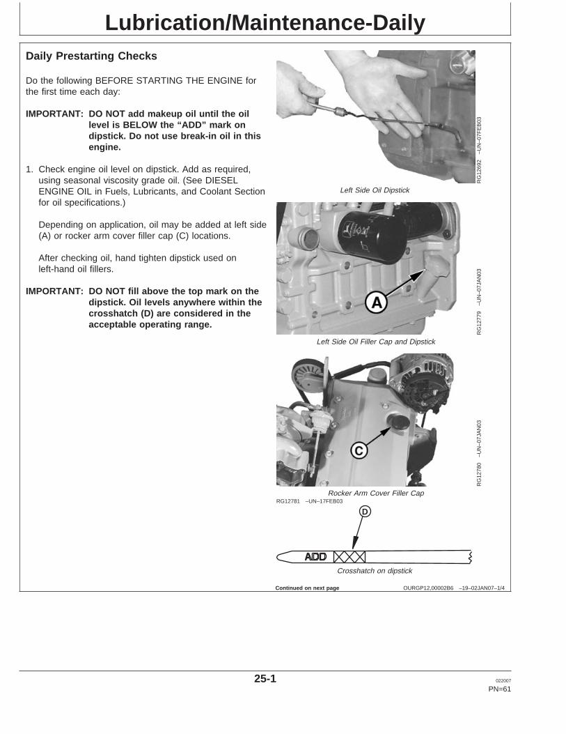
Check Engine Oil Level Daily
RG
1336
1–U
N–0
6FE
B04
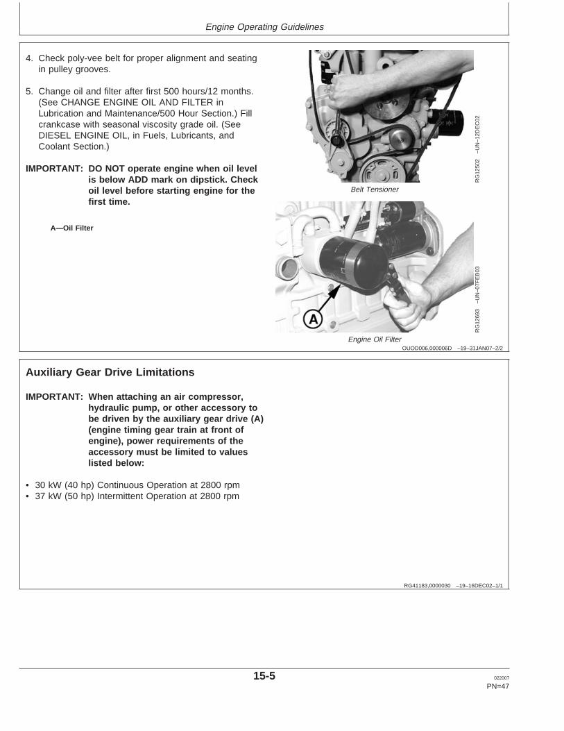
Oil Pressure and Coolant Temperature Gauges
A—Oil PressureB—Coolant Temperature
IMPORTANT: This engine is normally factory-filledwith John Deere PLUS-50 10W-30 oil,but can be shipped without oil tocomply with certain legislations. In thiscase, fill engine with John DeerePLUS-50 10W-30 oil.
NOTE: The use of BREAK-IN oils is not required for thisengine. Perform the following steps to break-inyour engine properly during the first 100 hours.Factory-fill oil and filter are suitable for extended500-hour drain interval, provided diesel fuel sulfurcontent is less than 0.10% (1000 ppm).
Before starting, fill engine with seasonal viscosity grade oiland with coolant meeting specifications. (See DIESELENGINE OIL and DIESEL ENGINE COOLANTSPECIFICATIONS in Fuels, Lubricants, and CoolantSection.)
1. During the first 20 hours, avoid prolonged periods ofengine idling or sustained maximum load operation.Warm-up engine carefully and operate at normal loads.If engine will idle longer than 5 minutes, stop engine.
2. Check oil level daily or every 10 hours during enginebreak-in period. If oil must be added during this period,use John Deere PLUS-50 10W-30 oil. (See DIESELENGINE OIL in Fuels, Lubricants, and Coolantsection.)
3. Watch oil pressure (A) and coolant temperature (B)closely during break-in period. Also check coolant leveldaily or every 10 hours and check for leaks.
PLUS-50 is a trademark of Deere & Company. Continued on next page
15-4 022007
PN=46
Engine Operating Guidelines
OUOD006,000006D –19–31JAN07–2/2
RG
1250
2–U
N–1
2DE
C02
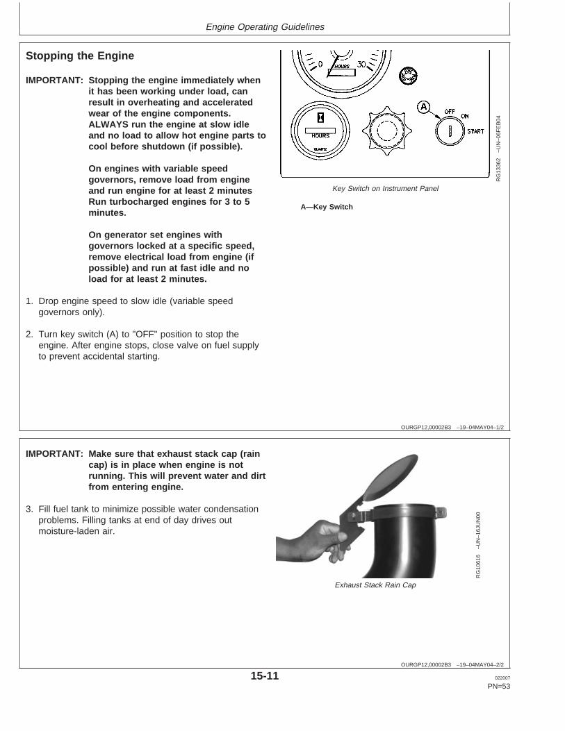
Belt Tensioner
RG
1269
3–U
N–0
7FE
B03
Engine Oil Filter
A—Oil Filter
4. Check poly-vee belt for proper alignment and seatingin pulley grooves.
5. Change oil and filter after first 500 hours/12 months.(See CHANGE ENGINE OIL AND FILTER inLubrication and Maintenance/500 Hour Section.) Fillcrankcase with seasonal viscosity grade oil. (SeeDIESEL ENGINE OIL, in Fuels, Lubricants, andCoolant Section.)
IMPORTANT: DO NOT operate engine when oil levelis below ADD mark on dipstick. Checkoil level before starting engine for thefirst time.
RG41183,0000030 –19–16DEC02–1/1
Auxiliary Gear Drive Limitations
IMPORTANT: When attaching an air compressor,hydraulic pump, or other accessory tobe driven by the auxiliary gear drive (A)(engine timing gear train at front ofengine), power requirements of theaccessory must be limited to valueslisted below:
• 30 kW (40 hp) Continuous Operation at 2800 rpm• 37 kW (50 hp) Intermittent Operation at 2800 rpm
15-5 022007
PN=47
Engine Operating Guidelines
OURGP12,0000101 –19–04JAN07–1/2
Starting The Engine
TS
220
–UN
–23A
UG
88
Use Proper Ventilation
RG
1336
6–U
N–1
2FE
B04
Starting Engine Using Reset Button and Key Switch
A—Reset ButtonB—Key Switch
The following instructions apply to the optional controlsand instruments available on John Deere Industrial andGenerator Power Units only. The controls and instrumentsfor your engine may be different from those shown here.Always follow manufacturer’s instructions and familiarizeyourself with the correct starting procedure.
CAUTION: Before starting engine in a confinedbuilding, install proper outlet exhaustventilation equipment. Always use safetyapproved fuel storage and piping.
NOTE: If temperature is below 0° C (32° F), it may benecessary to use cold weather starting aids. (SeeCOLD WEATHER OPERATION, later in thissection).
1. Perform all prestarting checks outlined in Lubrication &Maintenance/Daily Section later in this manual.
2. Disengage engine rear driveline (if equipped) or genset drive.
3. Open the fuel supply shut-off valve, if equipped.
4. Place the speed control lever in the “START” position,if equipped.
IMPORTANT: Do not operate the starter for more than30 seconds at a time. To do so mayoverheat the starter. If the engine doesnot start the first time, wait at least 2minutes before trying again. If enginedoes not start after four attempts, seeTroubleshooting Section.
5. Press reset button (A) while turning key switch (B) to“START” position and hold until engine starts. Releasekey and button once engine starts; key automaticallyreturns to “ON” position and instrument panel gaugesstart operating.
6. Warm-up engine for at least 5 minutes before applyinga load. (See WARMING-UP ENGINE, later in thissection.)
15-6 022007
PN=48
Continued on next page
Engine Operating Guidelines
OURGP12,0000101 –19–04JAN07–2/2
7. Check all gauges for normal operation. If operation isnot normal, stop engine immediately and determinecause.
OURGP12,00002B0 –19–16FEB07–1/2
Cold Weather Starting
RG
1353
2–U
N–0
7MA
Y04
Using Preheat Button to Activate Glow Plugs
C—Preheat Button
When outside temperatures fall below 0°C (32° F) it maybe necessary to consider using cold weather starting aids.Engines are equipped with standard glow plugs and acold start advance mechanism.
CAUTION: NEVER USE ANY STARTING FLUIDas a starting aid with these glow plug-equippedengines as it could cause an explosion andpossible personal injury.
Additionally, your PowerTech Engines may be fitted witha block heater, and increased capacity battery and/orlower viscosity oil may also be used. See your local JohnDeere engine distributor or servicing dealer forrecommendations.
1. Perform all prestarting checks outlined in Lubrication &Maintenance/Daily Section later in this manual.
2. Disengage engine rear driveline (if equipped) or genset drive.
3. Open the fuel supply shut-off valve, if equipped.
4. Place the throttle knob or speed control lever in the“START” position, if equipped.
5. Press and hold preheat button (C) for 10-30 seconds,as needed. This activates the glow plugs to warm thecombustion chamber.
PowerTech is a trademark of Deere & Company Continued on next page
15-7 022007
PN=49
Engine Operating Guidelines
OURGP12,00002B0 –19–16FEB07–2/2
RG
1336
6–U
N–1
2FE
B04
Starting Engine Using Reset Button and Key Switch
A—Reset ButtonB—Key Switch
IMPORTANT: Do not operate the starter for more than30 seconds at a time. To do so mayoverheat the starter. If the engine doesnot start the first time, wait at least 2minutes before trying again. If enginedoes not start after four attempts, seeTroubleshooting Section.
6. Press reset button (A) while turning key switch (B) to“START” position and hold until engine starts. Releasekey and button once engine starts; key automaticallyreturns to “ON” position and instrument panel gaugesstart operating.
7. Warm-up engine for at least 5 minutes before applyinga load. (See WARMING ENGINE, later in this section.)
15-8 022007
PN=50
Engine Operating Guidelines
OURGP12,00002B1 –19–02JAN07–1/1
Warming Engine
RG
1336
1–U
N–0
6FE
B04
Oil Pressure and Coolant Temperature Gauges
A—Oil PressureB—Coolant Temperature
IMPORTANT: To assure proper lubrication, operateengine at or below 1200 rpm with noload for 1–2 minutes. Extend this period2–4 minutes when operating attemperatures below freezing.
1. Check oil pressure gauge (A) as soon as engine starts.If gauge needle does not rise above minimum oilpressure specification of 150 kPa (1.50 bar) (22.0 psi)within 5 seconds, stop the engine and determine thecause. Normal engine oil pressure is 360 ± 105 kPa(3.60 ± 1.05 bar) (52 ± 15 psi) at rated full load speed(1800–2800 rpm) with oil at normal operatingtemperature of 125° C (257° F). This oil pressure canvary within the ranges given above.
NOTE: On certain engines, the oil pressure and coolanttemperature gauges are replaced by indicatorwarning lights. The lights must be "OFF" whenengine is running.
2. Watch coolant temperature gauge (B). Do not placeengine under full load until it is properly warmed up.The normal engine coolant temperature range is 82° –94° C (180° – 201° F).
NOTE: It is a good practice to operate the engine under alighter load and at lower speeds than normal forthe first few minutes after start-up.
15-9 022007
PN=51
Engine Operating Guidelines
OURGP12,00000FC –19–18MAY04–1/1
Avoid Excessive Engine Idling
Avoid excessive engine idling. Prolonged idling may causethe engine coolant temperature to fall below its normalrange. This, in turn, causes crankcase oil dilution, due toincomplete fuel combustion, and permits formation ofgummy deposits on valves, pistons, and piston rings. Italso promotes rapid accumulation of engine sludge andunburned fuel in the exhaust system.
Once an engine is warmed to normal operatingtemperatures, engine should be idled at slow idle speed.(See ENGINE POWER RATING AND SPEEDSPECIFICATIONS in the Specifications Section for slowidle speed information.) If an engine will be idling for morethan 5 minutes, stop and restart later.
OURGP12,00002B2 –19–04MAY04–1/1
Locking Throttle at Preset Speed
RG
1353
3–U
N–0
7MA
Y04
Locking Throttle
A—Locking Knob
1. Push in/pull out throttle to desired setting.2. Rotate locking knob (A), at base of throttle, clockwise
to lock the throttle in place.
15-10 022007
PN=52
Engine Operating Guidelines
OURGP12,00002B3 –19–04MAY04–1/2
Stopping the Engine
RG
1336
2–U
N–0
6FE
B04
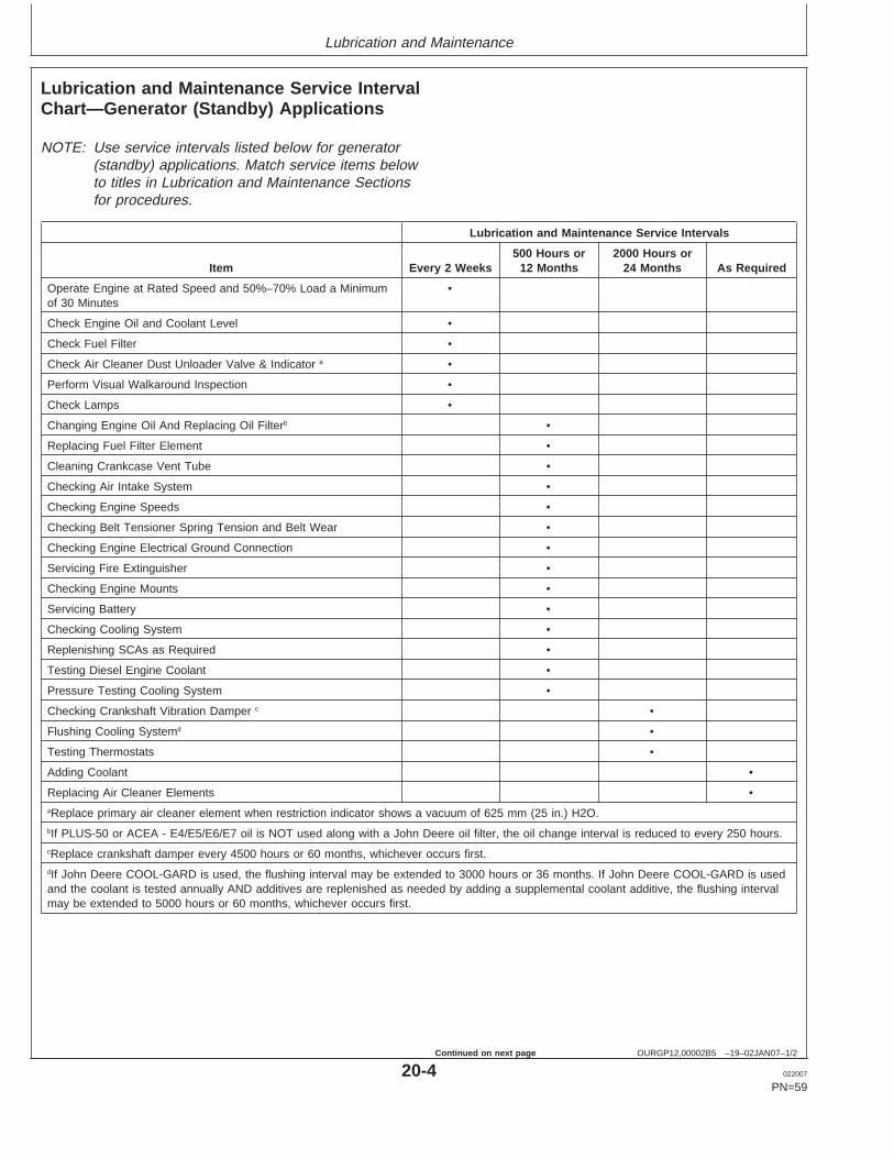
Key Switch on Instrument Panel
A—Key Switch
IMPORTANT: Stopping the engine immediately whenit has been working under load, canresult in overheating and acceleratedwear of the engine components.ALWAYS run the engine at slow idleand no load to allow hot engine parts tocool before shutdown (if possible).
On engines with variable speedgovernors, remove load from engineand run engine for at least 2 minutesRun turbocharged engines for 3 to 5minutes.
On generator set engines withgovernors locked at a specific speed,remove electrical load from engine (ifpossible) and run at fast idle and noload for at least 2 minutes.
1. Drop engine speed to slow idle (variable speedgovernors only).
2. Turn key switch (A) to "OFF" position to stop theengine. After engine stops, close valve on fuel supplyto prevent accidental starting.
OURGP12,00002B3 –19–04MAY04–2/2
RG
1061
6–U
N–1
6JU
N00
Exhaust Stack Rain Cap
IMPORTANT: Make sure that exhaust stack cap (raincap) is in place when engine is notrunning. This will prevent water and dirtfrom entering engine.
3. Fill fuel tank to minimize possible water condensationproblems. Filling tanks at end of day drives outmoisture-laden air.
15-11 022007
PN=53
Engine Operating Guidelines
RG,RG34710,5564 –19–27JUL06–1/2
Using a Booster Battery or Charger
TS
204
–UN
–23A
UG
88
Exploding Battery
RG
4678
–UN
–14D
EC
88
12-Volt System
RG
4698
–UN
–14D
EC
88
24-Volt System
A—12-Volt Machine Battery (ies)B—12-Volt Booster Battery (ies)C—Booster CableD—Cable to Starting Motor
A 12-volt booster battery can be connected in parallel withbattery (ies) on the unit to aid in cold weather starting.ALWAYS use heavy duty jumper cables.
CAUTION: Gas given off by battery is explosive.Keep sparks and flames away from battery.Before connecting or disconnecting a batterycharger, turn charger off. Make last connectionand first disconnection at a point away frombattery. Always connect NEGATIVE (–) cablelast and disconnect this cable first.
WARNING: Battery posts, terminals, and relatedaccessories contain lead and lead compounds, chemicalsknown to the State of California to cause cancer andreproductive harm. Wash hands after handling.
IMPORTANT: Be sure polarity is correct beforemaking connections. Reversed polaritywill damage electrical system. Alwaysconnect positive to positive andnegative to ground. Always use 12-voltbooster battery for 12-volt electricalsystems and 24-volt booster battery(ies) for 24-volt electrical systems.
1. Connect booster battery or batteries to produce therequired system voltage for your engine application.
NOTE: To avoid sparks, DO NOT allow the free ends ofjumper cables to touch the engine.
2. Connect one end of jumper cable to the POSITIVE (+)post of the booster battery.
3. Connect the other end of the jumper cable to thePOSITIVE (+) post of battery connected to starter.
4. Connect one end of the other jumper cable to theNEGATIVE (–) post of the booster battery.
5. ALWAYS complete the hookup by making the lastconnection of the NEGATIVE (–) cable to a goodground on the engine frame and away from the battery(ies).
15-12 022007
PN=54
Continued on next page
Engine Operating Guidelines
RG,RG34710,5564 –19–27JUL06–2/2
6. Start the engine. Disconnect jumper cablesimmediately after engine starts. Disconnect NEGATIVE(–) cable first.
15-13 022007
PN=55
Lubrication and Maintenance
OURGP12,00002B4 –19–05MAY04–1/1
Observe Service Intervals
RG
1353
4–U
N–0
7MA
Y04
Instrument Panel with Optional Hour Meter
A—Hour Meter
Using hour meter (A) (if equipped) as guide, perform allservices at the hourly intervals indicated on followingpages. At each scheduled maintenance interval, performall previous maintenance operations in addition to theones specified. Keep a record of hourly intervals andservices performed using charts provided in Lubricationand Maintenance Records Section.
IMPORTANT: Recommended service intervals are fornormal operating conditions. ServiceMORE OFTEN if engine is operatedunder adverse conditions. Neglectingmaintenance can result in failures orpermanent damage to the engine.
DPSG,OUOE003,20 –19–06JAN99–1/1
Use Correct Fuels, Lubricants, and Coolant
TS
100
–UN
–23A
UG
88
IMPORTANT: Use only fuels, lubricants, and coolantsmeeting specifications outlined inFuels, Lubricants, and Coolant Sectionwhen servicing your John DeereEngine.
Consult your John Deere engine distributor, servicingdealer or your nearest John Deere Parts Network forrecommended fuels, lubricants, and coolant. Alsoavailable are necessary additives for use when operatingengines in tropical, arctic, or any other adverse conditions.
20-1 022007
PN=56
Lubrication and Maintenance
OURGP12,00000FD –19–02JAN07–1/2
Lubrication and Maintenance Service IntervalChart—Standard Industrial Engines
NOTE: The service intervals below are for standardindustrial engines. Match service items below totitles in Lubrication and Maintenance Sections forprocedures.
Checking Fuses •aReplace primary air cleaner element when restriction indicator shows a vacuum of 625 mm (25 in.) H2O.bIf PLUS-50 or ACEA - E4/E5/E6/E7 oil is NOT used along with a John Deere oil filter, the oil change interval is reduced to every 250 hours.cReplace crankshaft damper every 4500 hours or 60 months, whichever occurs first.dIf John Deere COOL-GARD is used, the flushing interval may be extended to 3000 hours or 36 months. If John Deere COOL-GARD is usedand the coolant is tested annually AND additives are replenished as needed by adding a supplemental coolant additive, the flushing intervalmay be extended to 5000 hours or 60 months, whichever occurs first.
Lubrication and Maintenance Service IntervalChart—Generator (Standby) Applications
NOTE: Use service intervals listed below for generator(standby) applications. Match service items belowto titles in Lubrication and Maintenance Sectionsfor procedures.
Lubrication and Maintenance Service Intervals
500 Hours or 2000 Hours orItem Every 2 Weeks 12 Months 24 Months As Required
Operate Engine at Rated Speed and 50%–70% Load a Minimum •of 30 Minutes
Check Engine Oil and Coolant Level •
Check Fuel Filter •
Check Air Cleaner Dust Unloader Valve & Indicator a •
Perform Visual Walkaround Inspection •
Check Lamps •
Changing Engine Oil And Replacing Oil Filterb •
Replacing Fuel Filter Element •
Cleaning Crankcase Vent Tube •
Checking Air Intake System •
Checking Engine Speeds •
Checking Belt Tensioner Spring Tension and Belt Wear •
Checking Engine Electrical Ground Connection •
Servicing Fire Extinguisher •
Checking Engine Mounts •
Servicing Battery •
Checking Cooling System •
Replenishing SCAs as Required •
Testing Diesel Engine Coolant •
Pressure Testing Cooling System •
Checking Crankshaft Vibration Damper c •
Flushing Cooling Systemd •
Testing Thermostats •
Adding Coolant •
Replacing Air Cleaner Elements •aReplace primary air cleaner element when restriction indicator shows a vacuum of 625 mm (25 in.) H2O.bIf PLUS-50 or ACEA - E4/E5/E6/E7 oil is NOT used along with a John Deere oil filter, the oil change interval is reduced to every 250 hours.cReplace crankshaft damper every 4500 hours or 60 months, whichever occurs first.dIf John Deere COOL-GARD is used, the flushing interval may be extended to 3000 hours or 36 months. If John Deere COOL-GARD is usedand the coolant is tested annually AND additives are replenished as needed by adding a supplemental coolant additive, the flushing intervalmay be extended to 5000 hours or 60 months, whichever occurs first.
20-4 022007
PN=59
Continued on next page
Lubrication and Maintenance
OURGP12,00002B5 –19–02JAN07–2/2
Lubrication and Maintenance Service Intervals
500 Hours or 2000 Hours orItem Every 2 Weeks 12 Months 24 Months As Required
Replacing Poly-Vee Belt •
Checking Fuses •
Checking Air Compressor (If Equipped) •
Adjusting Speed Gain •
Bleeding Fuel System •
20-5 022007
PN=60
Lubrication/Maintenance-Daily
OURGP12,00002B6 –19–02JAN07–1/4
Daily Prestarting Checks
RG
1269
2–U
N–0
7FE
B03
Left Side Oil Dipstick
RG
1277
9–U
N–0
7JA
N03
Left Side Oil Filler Cap and Dipstick
RG
1278
0–U
N–0
7JA
N03
Rocker Arm Cover Filler Cap
DRG12781 –UN–17FEB03
Crosshatch on dipstick
Do the following BEFORE STARTING THE ENGINE forthe first time each day:
IMPORTANT: DO NOT add makeup oil until the oillevel is BELOW the “ADD” mark ondipstick. Do not use break-in oil in thisengine.
1. Check engine oil level on dipstick. Add as required,using seasonal viscosity grade oil. (See DIESELENGINE OIL in Fuels, Lubricants, and Coolant Sectionfor oil specifications.)
Depending on application, oil may be added at left side(A) or rocker arm cover filler cap (C) locations.
After checking oil, hand tighten dipstick used onleft-hand oil fillers.
IMPORTANT: DO NOT fill above the top mark on thedipstick. Oil levels anywhere within thecrosshatch (D) are considered in theacceptable operating range.
Continued on next page
25-1 022007
PN=61
Lubrication/Maintenance-Daily
OURGP12,00002B6 –19–02JAN07–2/4
TS
281
–UN
–23A
UG
88
High-Pressure Fluids
RG
6576
–UN
–20J
AN
93
Check Coolant Level in Radiator
RG
4675
–UN
–14D
EC
88
Fill Radiator
A—Fill Radiator
CAUTION: Explosive release of fluids frompressurized cooling system can cause seriousburns.
Only remove filler cap when engine is cold orwhen cool enough to touch with bare hands.Slowly loosen cap to first stop to relievepressure before removing completely.
2. Check the coolant level when engine is cold. Coolantlevel should be at bottom of filler neck. Fill radiator (A)with proper coolant solution if level is low. (SeeADDING COOLANT in Service As Required Section.)Check overall cooling system for leaks.
NOTE: Refer to your vehicle’s operator’s manual forrecommendations for non-John Deere suppliedaccessories.
IMPORTANT: Drain water from filter bowl daily toavoid premature failure of unit injectionpump.
3. Check the fuel filter for water or debris. If filter is fittedwith a see-through bowl, drain as needed based on adaily visual inspection.
IMPORTANT: Drain water into a suitable containerand dispose of properly.
a. Loosen drain plug (B) at bottom of fuel filter or bowl,if equipped, two or three turns.
b. Loosen air bleed plug (A) two full turns on fuel filtermounting and drain water from bottom until fuelstarts to drain out.
c. When fuel starts to drain out, tighten drain plugsecurely.
After draining water from the fuel filter, the filter mustbe primed by bleeding all air from the fuel system.
a. Operate primer plunger on the fuel filter header (C)until fuel flow is free from air bubbles.
b. Tighten bleed plug securely, continue operatingprimer until pumping action is not felt.
If the fuel system needs further bleeding of air, seeBLEEDING FUEL SYSTEM in Service As RequiredSection, later in this manual.
Continued on next page
25-3 022007
PN=63
Lubrication/Maintenance-Daily
OURGP12,00002B6 –19–02JAN07–4/4
RG
7332
A–U
N–2
2JA
N99
Dust Unloader Valve and Indicator Gauge
RG
1353
5–U
N–0
7MA
Y04
Key Switch in "ON" Position
A—Dust Unloader ValveB—Air Restriction Indicator
4. If the air cleaner has an automatic dust unloader valve(A), squeeze the unloader valve on air cleanerassembly to clear away any dust buildup.
If equipped with air intake restriction indicator gauge(B), check gauge to determine if air cleaner needs tobe serviced.
IMPORTANT: Maximum air intake restriction is 6.25kPa (0.06 bar) (1.0 psi) (25 in. H2O). Aclogged air cleaner element will causeexcessive intake restriction and areduced air supply to the engine.
5. Make a thorough inspection of the enginecompartment. Look for oil or coolant leaks, worn fanand accessory drive belts, loose connections and trashbuild-up. Remove trash buildup and have repairs madeas needed if leaks are found.
NOTE: Wipe all fittings, caps, and plugs beforeperforming any maintenance to reduce the chanceof system contamination.
Inspect:
• Radiator for leaks and trash build-up.• Air intake system hoses and connections for cracks
and loose clamps.• Fan, alternator, and accessory drive belts for cracks,
breaks or other damage.• Coolant pump for coolant leaks.
NOTE: It is normal for a small amount of leakage to occuras the engine cools down and parts contract.Excessive coolant leakage may indicate the needto replace the coolant pump. Contact your enginedistributor or servicing dealer for repairs.
6. Turn key switch to “ON” position and check lamps.“WATER” and “HEAT” lamps should be off, while “OIL”and “CHG” lamps should be lit.
Replace lamps as needed. If this does not solve anyproblems, see your John Deere dealer or distributor.
25-4 022007
PN=64
Lubrication/Maintenance-500 Hour/12 Month
OUOD006,0000074 –19–31JAN07–1/3
Changing Engine Oil and Replacing Filter
If John Deere PLUS-50 10W-30 or ACEA - E4, E5, E6,or E7 engine oil and a John Deere oil filter are used, theoil and filter change interval is every 500 hours or every12 months, whichever occurs first.
NOTE: If other than recommended oils or filters are used,the oil and filter change interval is reduced toevery 250 hours.
OILSCAN or OILSCAN PLUS is a John Deeresampling program to help you monitor machineperformance and identify potential problems before theycause serious damage. OILSCAN and OILSCANPLUS kits are available from your John Deere enginedistributor or servicing dealer. Oil samples should betaken prior to the oil change. Refer to instructionsprovided with kit.
PLUS-50 is a trademark of Deere & CompanyOILSCAN is a trademark of Deere & CompanyOILSCAN PLUS is a trademark of Deere & Company Continued on next page
30-1 022007
PN=65
Lubrication/Maintenance-500 Hour/12 Month
OUOD006,0000074 –19–31JAN07–2/3
RG
1278
3–U
N–1
8FE
B03
Oil Pan Drain Plug
RG
1269
3–U
N–0
7FE
B03
Removing Horizontal Oil Filter Element
RG
1282
2–U
N–0
9FE
B03
Removing Optional Vertical Oil Filter Element
A—Oil Filter Element
CAUTION: Metal surfaces of oil pan and drainplug maybe hot to the touch. Use care toprevent burns.
To change engine oil and oil filter:
1. Run engine approximately 5 minutes to warm up oil.Shut engine off.
2. Remove oil pan drain plug (arrow).
3. Drain crankcase oil from engine while warm.
4. Turn filter element (A) counterclockwise using asuitable filter wrench to remove. Discard oil filterelement.
NOTE: Depending on engine application, oil filter mayhave either a vertical or horizontal mounting.
5. Remove oil filter packing and clean filter mounting pad.
IMPORTANT: Filtration of oils is critical to properlubrication. Always change filterregularly. Use filter meeting John Deereperformance specifications.
NOTE: Apply a thin coat of engine oil to the entire filterpacking. DO NOT use grease.
6. Oil new packing and install new filter element. Handtighten element according to values printed on filterelement. If values are not provided, tighten element byhand approximately 3/4 — 1-1/4 turn after packingcontacts filter housing. DO NOT overtighten filterelement. If a filter wrench is used, be sure it is paddedto avoid damaging element.
7. Install oil pan drain plug with O-ring. If O-ring isdamaged, replace it.
8. Tighten drain plug to specifications.
SpecificationOil Pan Drain Plug With O-Ring—Torque 35 N•m (26 lb ft).............................................................................
30-2 022007
PN=66
Continued on next page
Lubrication/Maintenance-500 Hour/12 Month
OUOD006,0000074 –19–31JAN07–3/3
RG
1278
0–U
N–0
7JA
N03
Rocker Arm Cover Oil Fill
RG
1277
9A–U
N–0
7JA
N03
Optional Side Oil Fill
DRG12781 –UN–17FEB03
Crosshatch Marks on Dipstick
B—Optional Side Oil FillC—Rocker Arm Cover Oil FillD—Crosshatch Marks on Dipstick
9. Fill engine crankcase with correct John Deere engineoil through rocker arm cover opening (C) or side oilfiller (B) depending on engine application. (SeeDIESEL ENGINE OIL in Fuels, Lubricants, and CoolantSection for determining correct engine oil.)
To determine the correct oil fill quantity for your engine,see ENGINE CRANKCASE OIL CAPACITIES in theSpecifications Section of this manual.
IMPORTANT: Immediately after completing any oilchange, crank engine for 30 secondswithout permitting engine to start. Thiswill help insure adequate lubrication toengine components before enginestarts.
NOTE: Crankcase oil capacity may vary slightly.ALWAYS fill crankcase to within crosshatch marks(D) on dipstick. DO NOT overfill.
10. Start engine and run to check for possible leaks.
11. Stop engine and check oil level after 10 minutes. Oillevel reading should be within crosshatch marks (D)on dipstick.
30-3 022007
PN=67
Lubrication/Maintenance-500 Hour/12 Month
RG41183,0000046 –19–08JAN03–1/1
Replacing Fuel Filter Element
X98
11–U
N–2
3AU
G88
High-Pressure Fluids
RG
1278
2A–U
N–1
8FE
B03
Fuel Filter
A—Bleed PlugB—Drain PlugC—Primer ButtonD—Filter Element
CAUTION: Escaping fluid under pressure canpenetrate the skin causing serious injury.Relieve pressure before disconnecting fuel orother lines. Tighten all connections beforeapplying pressure. Keep hands and body awayfrom pinholes and nozzles which eject fluidsunder high pressure. Use a piece of cardboardor paper to search for leaks. Do not use yourhand.
If any fluid is injected into the skin, it must besurgically removed within a few hours by adoctor familiar with this type injury or gangrenemay result. Doctors unfamiliar with this type ofinjury may call the Deere & Company MedicalDepartment in Moline, Illinois, or otherknowledgeable medical source.
1. Close fuel shut-off valve, if equipped.
2. Thoroughly clean fuel filter assembly and surroundingarea.
3. Loosen drain plug (B) and drain fuel into a suitablecontainer.
4. Firmly grasp the filter element (A) and rotate itcounterclockwise 1/4 turn. Remove filter element.
5. Inspect filter mounting base for cleanliness. Clean asrequired.
6. Install new filter element by pushing up firmly intomounting base, then turn clockwise until it locks inplace. Be sure element is firmly seated in base.
NOTE: A plug is provided with the new element forplugging the used element.
7. Open fuel shut-off valve and bleed the fuel system bypressing down in the primer button (D) on top of filteruntil resistance is felt or fuel flows freely from the bleedplug. Tighten bleed plug (C).
30-4 022007
PN=68
Lubrication/Maintenance-500 Hour/12 Month
RG41183,000003C –19–31JAN07–1/1
Cleaning Crankcase Vent Tube
RG
1278
7–U
N–0
2JU
N03
Crankcase Vent Tube and Clamp
If you operate the engine in dusty conditions, clean thetube at shorter intervals.
1. Remove and clean crankcase vent tube (A) byloosening clamp (B) and hose clamp screw.
2. Install the vent tube and hose clamp screw. Tightenhose clamp cap screw to specification.
SpecificationVent Tube Clamp Cap Screw—Torque 40 N•m (30 lb ft).............................................................................
IMPORTANT: The air intake system must not leak.Any leak, no matter how small, mayresult in internal engine damage due toabrasive dirt and dust entering theintake system.
1. Inspect all intake hoses (piping) for cracks. Replace asnecessary.
2. Check clamps (A) on piping which connect the aircleaner, engine and, if present, turbocharger. Tightenclamps as necessary. This will help prevent dirt fromentering the air intake system through looseconnections causing internal engine damage.
3. If engine has a rubber dust unloader valve (B), inspectthe valve on bottom of air cleaner for cracks orplugging. Replace as necessary.
IMPORTANT: ALWAYS REPLACE primary air cleanerelement when air restriction indicatorshows a vacuum of 625 mm (25 in.)H2O, is torn, or visibly dirty. SeeREPLACING AIR CLEANER ELEMENTlater in Service As Required section.
4. Test air restriction indicator (C) for proper operation.Replace indicator as necessary.
IMPORTANT: If not equipped with air restrictionindicator, replace air cleaner elementsat 500 Hours or 12 Months, whicheveroccurs first.
RG41183,000003E –19–31JAN07–1/1
Check Engine Speeds
Observe tachometer reading (if equipped) and checkspeeds per specification (See correct speeds listed inENGINE POWER RATINGS). If speeds requireadjustment, contact your John Deere dealer or distributor.
30-6 022007
PN=70
Lubrication/Maintenance-500 Hour/12 Month
RG41183,0000048 –19–15FEB07–1/3
Checking Belt Tensioner Spring Tension andBelt Wear
Belt drive systems equipped with an automatic (spring)belt tensioner cannot be adjusted or repaired. Theautomatic belt tensioner is designed to maintain properbelt tension over the life of the belt. If tensioner springtension is not within specification, replace tensionerassembly.
RG41183,0000048 –19–15FEB07–2/3
RG
1297
2–U
N–0
5JU
N03
Belt Wear Inspection
A—Belt TensionerB—Poly-Vee Belt
Checking Belt Wear
The belt tensioner is designed to operate within the limitof arm movement when correct belt length and geometryis used.
Visually inspect belt for excessive wear and cracks. SeeReplacing Fan and Alternator Belt in Section 40.
Continued on next page
30-7 022007
PN=71
Lubrication/Maintenance-500 Hour/12 Month
RG41183,0000048 –19–15FEB07–3/3
RG
1282
5–U
N–1
9FE
B03
Marks on Tensioner
RG
1282
4–U
N–1
9FE
B03
Align Marks
RG
1297
1–U
N–0
4JU
N03
Align Torque Wrench With Pulley And Tensioner
A—Mark On Swing ArmB—Mark On Tensioner Mounting BaseC—Torque Wrench
Checking Tensioner Spring Tension
A belt tension gauge will not give an accurate measure ofthe belt tension when automatic spring tensioner is used.Measure tensioner spring tension using a torque wrenchand procedure outlined below:
1. Release tension on belt using a breaker bar andsocket on tension arm. Remove belt from pulleys.
2. Release tension on tension arm and remove breakerbar.
3. Put a mark (A) on swing arm of tensioner as shown.
4. Measure 21 mm (0.83 in.) from (A) and put a mark (B)on tensioner mounting base.
5. Install torque wrench (C) so that it is aligned withcenter of pulley and tensioner. Rotate the swing armwith the torque wrench until marks (A and B) arealigned.
6. Record torque wrench measurement and compare withspecification below. Replace tensioner assembly asrequired.
NOTE: Threads on belt tensioner roller cap screw areLEFT-HAND threads
30-8 022007
PN=72
Lubrication/Maintenance-500 Hour/12 Month
RG41183,0000049 –19–08JAN03–1/1
Checking Engine Electrical GroundConnections
Keep all engine ground connections clean and tight toprevent electrical arcing which can damage electricalcomponents.
RG,RG34710,5567 –19–02JAN07–1/1
Servicing Fire Extinguisher
RW
4918
–UN
–15D
EC
88
Fire ExtinguisherA—Fire Extinguisher
A fire extinguisher (A) is available from your authorizedservicing dealer or engine distributor.
Read and follow the instructions which are packaged withit. The extinguisher should be inspected at least every 500hours of engine operation or once a month. Onceextinguisher is operated, no matter how long, it must berecharged. Keep record of inspections on the tag whichcomes with the extinguisher instruction booklet.
DPSG,RG34710,111 –19–07JAN02–1/1
Checking Engine Mounts
Engine mounting is the responsibility of the vehicle orgenerator manufacturer. Follow manufacturer’s guidelinesfor mounting specifications.
IMPORTANT: Use only Grade SAE 8 or higher gradeof hardware for engine mounting.
1. Check the engine mounting bracket, vibration isolators,and mounting bolts on support frame and engine blockfor tightness. Tighten as necessary.
2. Inspect overall condition of vibration isolators, ifequipped. Replace isolators if rubber has deterioratedor mounts have collapsed, as necessary.
30-9 022007
PN=73
Lubrication/Maintenance-500 Hour/12 Month
RG,RG34710,5568 –19–20MAY96–1/2
Servicing Battery
TS
204
–UN
–23A
UG
88
Exploding Battery
CAUTION: Battery gas can explode. Keepsparks and flames away from batteries. Use aflashlight to check battery electrolyte level.
Never check battery charge by placing a metalobject across the posts. Use a voltmeter orhydrometer.
Always remove grounded NEGATIVE (–) batteryclamp first and replace it last.
WARNING: Battery posts, terminals, and relatedaccessories contain lead and lead compounds, chemicalsknown to the State of California to cause cancer andreproductive harm. Wash hands after handling.
1. On regular batteries, check electrolyte level. Fill eachcell to bottom of filler neck with distilled water.
NOTE: Low-maintenance or maintenance-free batteriesshould require little additional service. However,electrolyte level can be checked by cutting thecenter section of decal on dash-line, andremoving cell plugs. If necessary, add clean, softwater to bring level to bottom of filler neck.
2. Keep batteries clean by wiping them with a damp cloth.Keep all connections clean and tight. Remove anycorrosion, and wash terminals with a solution of 1 partbaking soda and 4 parts water. Tighten all connectionssecurely.
NOTE: Coat battery terminals and connectors with amixture of petroleum jelly and baking soda toretard corrosion.
3. Keep battery fully charged, especially during coldweather. If a battery charger is used, turn charger offbefore connecting charger to battery(ies). AttachPOSITIVE (+) battery charger lead to POSITIVE (+)battery post. Then attach NEGATIVE (–) batterycharger lead to a good ground.
30-10 022007
PN=74
Continued on next page
Lubrication/Maintenance-500 Hour/12 Month
RG,RG34710,5568 –19–20MAY96–2/2
TS
203
–UN
–23A
UG
88
Sulfuric Acid
CAUTION: Sulfuric acid in battery electrolyte ispoisonous. It is strong enough to burn skin, eatholes in clothing, and cause blindness ifsplashed into eyes.
Avoid the hazard by:
1. Filling batteries in a well-ventilated area.2. Wearing eye protection and rubber gloves.3. Avoiding breathing fumes when electrolyte is
added.4. Avoiding spilling or dripping electrolyte.5. Use proper jump start procedure.
If you spill acid on yourself:
1. Flush your skin with water.2. Apply baking soda or lime to help neutralize
the acid.3. Flush your eyes with water for 10–15
minutes. Get medical attention immediately.
If acid is swallowed:
1. Drink large amounts of water or milk.2. Then drink milk of magnesia, beaten eggs, or
vegetable oil.3. Get medical attention immediately.
In freezing weather, run engine at least 30 minutes toassure thorough mixing after adding water to battery.
If necessary to replace battery(ies), replacements mustmeet or exceed the following recommended capacities at-18°C (0°F):
Specification12 Volt Standard Duty Starter—Cold Cranking Amps 640............................................................................12 Volt Heavy Duty Starter—ColdCranking Amps 800.....................................................................................24 Volt Standard Duty Starter—Cold Cranking Amps 570............................................................................
30-11 022007
PN=75
Lubrication/Maintenance-500 Hour/12 Month
RG,RG34710,5580 –19–20MAY96–1/1
Checking Cooling System
TS
281
–UN
–23A
UG
88
High-Pressure Fluids
CAUTION: Explosive release of fluids frompressurized cooling system can cause seriousburns.
Shut off engine. Only remove filler cap whencool enough to touch with bare hands. Slowlyloosen cap to first stop to relieve pressurebefore removing completely.
IMPORTANT: Air must be expelled from coolingsystem when system is refilled. Loosentemperature sending unit fitting at rearof cylinder head or plug in thermostathousing to allow air to escape whenfilling system. Retighten fitting or plugwhen all the air has been expelled.
1. Visually check entire cooling system for leaks. Tightenall clamps securely.
2. Thoroughly inspect all cooling system hoses for hard,flimsy, or cracked condition. Replace hoses if any ofthe above conditions are found.
30-12 022007
PN=76
Lubrication/Maintenance-500 Hour/12 Month
DPSG,OUOD002,1921 –19–27JUL06–1/2
Replenishing Supplemental CoolantAdditives (SCAs) Between Coolant Changes
RG
6261
–UN
–08D
EC
97
Radiator Coolant Check
RG
6262
–UN
–05D
EC
97
JT07298 Coolant/Battery Tester
IMPORTANT: Do not add supplemental coolantadditives when the cooling system isdrained and refilled with John DeereCOOL-GARD
NOTE: If system is to be filled with coolant that does notcontain SCAs, the coolant must be precharged.Determine the total system capacity and premixwith 3% John Deere Coolant Conditioner.
Through time and use, the concentration of coolantadditives is gradually depleted during engine operation.Periodic replenishment of inhibitors is required, even whenJohn Deere COOL-GARD is used. The cooling systemmust be recharged with additional supplemental coolantadditives available in the form of liquid coolant conditioner.
Maintaining the correct coolant conditioner concentration(SCAs) and freeze point is essential in your coolingsystem to protect against rust, liner pitting and corrosion,and freeze-ups due to incorrect coolant dilution.
John Deere LIQUID COOLANT CONDITIONER isrecommended as a supplemental coolant additive inJohn Deere engines.
DO NOT mix one brand of SCA with a different brand.
Test the coolant solution at 500 hours or 12 months ofoperation using either John Deere coolant test strips or aCOOLSCAN or COOLSCAN PLUS analysis. If aCOOLSCAN or COOLSCAN PLUS analysis is notavailable, recharge the system per instructions printed onlabel of John Deere Liquid Coolant Conditioner.
COOL-GARD is a trademark of Deere & CompanyCOOLSCAN is a trademark of Deere & CompanyCOOLSCAN PLUS is a trademark of Deere & Company Continued on next page
30-13 022007
PN=77
Lubrication/Maintenance-500 Hour/12 Month
DPSG,OUOD002,1921 –19–27JUL06–2/2
IMPORTANT: ALWAYS maintain coolant at correctlevel and concentration. DO NOToperate engine without coolant even fora few minutes.
If frequent coolant makeup is required,the glycol concentration should bechecked with JT07298 Coolant/BatteryTester to ensure that the desired freezepoint is maintained. Followmanufacturer’s instructions providedwith Coolant/Battery Tester.
Add the manufacturer’s recommended concentration ofsupplemental coolant additive. DO NOT add more thanthe recommended amount.
The use of non-recommended supplemental coolantadditives may result in additive drop-out and gelation ofthe coolant.
If other coolants are used, consult the coolant supplierand follow the manufacturer’s recommendation for use ofsupplemental coolant additives.
See DIESEL ENGINE COOLANTS ANDSUPPLEMENTAL ADDITIVE INFORMATION for propermixing of coolant ingredients before adding to the coolingsystem.
30-14 022007
PN=78
Lubrication/Maintenance-500 Hour/12 Month
DX,COOL9 –19–19DEC03–1/1
Testing Diesel Engine Coolant
Testing Diesel Engine Coolant
Maintaining adequate concentrations of glycol andinhibiting additives in the coolant is critical to protectthe engine and cooling system against freezing,corrosion, and cylinder liner erosion and pitting.
Test the coolant solution at intervals of 12 months orless and whenever excessive coolant is lost throughleaks or overheating.
Coolant test strips
Coolant test strips are available from your John Deeredealer. These test strips provide a simple, effective
method to check the freeze point and additive levels ofyour engine coolant.
Compare the results to the supplemental coolantadditive (SCA) chart to determine the amount ofinhibiting additives in your coolant and whether moreJohn Deere COOLANT CONDITIONER should beadded.
COOLSCAN and COOLSCAN PLUS
For a more thorough evaluation of your coolant,perform a COOLSCAN or COOLSCAN PLUS analysis,where available. See your John Deere dealer forinformation.
COOLSCAN is a trademark of Deere & CompanyCOOLSCAN PLUS is a trademark of Deere & Company
30-15 022007
PN=79
Lubrication/Maintenance-500 Hour/12 Month
RG,RG34710,5586 –19–07JAN02–1/1
Pressure Testing Cooling System
RG
6557
–UN
–20J
AN
93
Test Radiator Cap
RG
6558
–UN
–20J
AN
93
Test Cooling System
CAUTION: Explosive release of fluids frompressurized cooling system can causeserious burns.
Shut off engine. Only remove filler cap whencool enough to touch with bare hands.Slowly loosen cap to first stop to relievepressure before removing completely.
Test Radiator Cap
1. Remove radiator cap and attach to D05104STTester as shown.
2. Pressurize cap to specification listed. Gauge shouldhold pressure for 10 seconds within the normalrange if cap is acceptable.
If gauge does not hold pressure, replace radiatorcap.
SpecificationRadiator Cap Holding Pressure(Not Opening For 10Seconds)—Pressure 70 kPa (0.7 bar) (10 psi)
minimum....................................
3. Remove the cap from gauge, turn it 180°, andretest cap. This will verify that the firstmeasurement was accurate.
Test Cooling System
NOTE: Engine should be warmed up to test overallcooling system.
1. Allow engine to cool, then carefully remove radiatorcap.
2. Fill radiator with coolant to the normal operatinglevel.
IMPORTANT: DO NOT apply excessive pressure tocooling system, doing so maydamage radiator and hoses.
3. Connect gauge and adapter to radiator filler neck.Pressurize cooling system to specification listed forradiator cap.
4. With pressure applied, check all cooling systemhose connections, radiator, and overall engine forleaks.
If leakage is detected, correct as necessary andpressure test system again.
If no leakage is detected, but the gauge indicated adrop in pressure, coolant may be leaking internallywithin the system or at the block-to-head gasket.Have your engine distributor or servicing dealercorrect this problem immediately.
30-16 022007
PN=80
Lubrication/Maintenance-2000 Hour/24 Month
OUOD006,000006E –19–02JAN07–1/1
Checking Crankshaft Vibration Damper (IfEquipped)
RG
1291
7–U
N–1
6MA
Y03
Vibration Damper
RG
1278
8–U
N–2
1JA
N03
Rotating Crankshaft Using JDG1704
RG
1291
8–U
N–1
6MA
Y03
Vibration Damper Radial (Concentricity)
1. Grasp vibration damper with both hands and attempt toturn it in both directions. If rotation is felt, damper isdefective and should be replaced.
IMPORTANT: The vibration damper assembly is notrepairable and should be replaced every4500 hours or 60 months, whicheveroccurs first.
2. Check vibration damper radial runout by positioning adial indicator so probe contacts damper outer diameter.
3. Remove starter motor.
4. Rotate crankshaft using JDG1704 or JDG10221Flywheel Turning Tool as shown. This tool is availablefrom your John Deere dealer or distributor.
5. Note dial indicator reading. If runout exceedsspecifications given below, replace vibration damper.
SpecificationVibration Damper—MaximumRadial Runout 1.00 mm (0.040 in.).............................................................
6. Remove tool and reinstall starter motor. Connect wiringand tighten mounting cap screws to specifications.
SpecificationStarter Motor Mounting CapScrews—Torque 80 N•m (59 lb-ft)..............................................................
35-1 022007
PN=81
Lubrication/Maintenance-2000 Hour/24 Month
OURGP12,00002B8 –19–03JAN07–1/3
Flushing and Refilling Cooling System
TS
281
–UN
–23A
UG
88
High-Pressure Fluids
RG
6576
–UN
–20J
AN
93
Cooling System Filler Cap
RG
1253
4–U
N–1
2DE
C02
Engine Coolant Drain Valve
A—Engine Coolant Drain Valve
CAUTION: Explosive release of fluids frompressurized cooling system can cause seriousburns.
Shut off engine. Only remove filler cap whencool enough to touch with bare hands. Slowlyloosen cap to first stop to relieve pressurebefore removing completely.
NOTE: When John Deere COOL-GARD is used, the draininterval is 3000 hours or 36 months. The draininterval may be extended to 5000 hours or 60months of operation, provided that the coolantis tested annually AND additives arereplenished, as needed, by adding asupplemental coolant additive (SCA).
If COOL-GARD is not used, the flushing interval is2000 hours or 24 months of operation.
Drain old coolant, flush the entire cooling system, testthermostats, and fill with recommended clean coolant asfollows:
1. Pressure test entire cooling system and pressure cap ifnot previously done. (See PRESSURE TESTINGCOOLING SYSTEM, in the Lubrication andMaintenance/500 Hour/12 Month Section.)
2. Slowly open the engine cooling system filler cap orradiator cap to relieve pressure and allow coolant todrain faster.
3. Open engine block drain valve (A) on right side ofcoolant pump on engine front cover. Drain all coolantfrom engine block.
4. Open radiator drain valve. Drain all coolant fromradiator.
5. Remove coolant hose and thermostat at this time, ifnot previously done. (See TESTING THERMOSTATSOPENING TEMPERATURE later in this section.)
6. Close all drain valves after coolant has drained.
35-2 022007
PN=82
Continued on next page
Lubrication/Maintenance-2000 Hour/24 Month
OURGP12,00002B8 –19–03JAN07–2/3
RG
6576
–UN
–20J
AN
93
Radiator Cap
CAUTION: Do not run engine longer than 10minutes. Doing so may cause engine tooverheat which may cause burns when radiatorwater is draining.
7. Fill the cooling system with clean water. Run theengine about 10 minutes to stir up possible rust orsediment.
8. Stop engine, pull off lower radiator hose and removeradiator cap. Immediately drain the water from systembefore rust and sediment settle.
9. After draining water, close drain valves. Reinstallradiator cap and radiator hose and clamp. Fill thecooling system with clean water and a heavy dutycooling system cleaner such as Fleetguard
RESTORE and RESTORE PLUS. These productsmay be available from your John Deere dealer. Followmanufacturer’s directions on label.
10. After cleaning the cooling system, drain cleaner andfill with water to flush the system. Run the engineabout 10 minutes, remove radiator cap and pull offlower radiator hose to drain out flushing water.
11. Close all drain valves on coolant pump and radiator.Install thermostat. Reinstall radiator hose and tightenclamps securely.
IMPORTANT: Air must be expelled from coolingsystem when system is refilled. Loosentemperature sending unit fitting at rearof cylinder head or plug in thermostathousing to allow air to escape whenfilling system. Retighten fitting or plugafter filling cooling system.
12. Refill system with fresh coolant at radiator untilcoolant touches bottom of filler neck. Seespecification for capacity. (See ADDING COOLANT inService As Required Section.) Install radiator cap.
Fleetguard is a trademark of Cummins Engine Company, Inc.RESTORE is a trademark of Fleetguard.RESTORE PLUS is a trademark of Fleetguard.
35-3 022007
PN=83
Continued on next page
Lubrication/Maintenance-2000 Hour/24 Month
OURGP12,00002B8 –19–03JAN07–3/3
Specification2.4 L Engine— Coolant Capacity 2.6 L (2.7 qt)..........................................3.0 L Engine—Coolant Capacity 2.9 L (3.1 qt)...........................................
13. Run engine until it reaches operating temperature.This mixes the solution uniformly and circulates itthrough the entire system. The normal engine coolanttemperature range is 82°—94°C (180° — 201°F).
14. After running engine, check coolant level and entirecooling system for leaks.
Coolant Hose to Thermostat Housing (Earlier EngineShown)
A—Thermostat Hose Connection
To Remove Thermostat (Earlier Engines)
CAUTION: Explosive release of fluids frompressurized cooling system can cause seriousburns. DO NOT drain coolant until it has cooledbelow operating temperature. Always loosenradiator pressure cap or drain valve slowly torelieve pressure.
1. Visually inspect area around thermostat housing on topof engine timing gear cover for leaks.
2. Remove radiator pressure cap and partially draincooling system.
5. Remove thermostat and observe its closing action as itcools. In ambient air the thermostat should closecompletely. Closing action should be smooth and slow.
6. Replace any defective thermostat.
Continued on next page
35-6 022007
PN=86
Lubrication/Maintenance-2000 Hour/24 Month
RG41183,0000050 –19–02JAN07–4/4
RG
1279
1–U
N–2
1JA
N03
Installing Thermostat (Earlier Engine Shown)
To Install Thermostats (Earlier Engines)
1. Insert thermostat in housing as shown until both tabs(A) are fully engaged in the groove in the housingbore.
2. Install coolant hose to thermostat cover. Tighten clamp.
3. If not already done, fill cooling system and check forleaks.
IMPORTANT: Air must be expelled from coolingsystem when filling. Loosentemperature sending unit fitting at rearof cylinder head or plug in thermostathousing to allow air to escape whenfilling system. Tighten fitting or plugwhen all air has been expelled.
CAUTION: Explosive release of fluids frompressurized cooling system can cause seriousburns. DO NOT drain coolant until it has cooledbelow operating temperature. Always loosenradiator pressure cap or drain valve slowly torelieve pressure.
1. Visually inspect area around thermostat housing on topof engine timing gear cover for leaks.
2. Remove radiator pressure cap and partially draincooling system.
5. Remove thermostat and observe its closing action as itcools. In ambient air the thermostat should closecompletely. Closing action should be smooth and slow.
6. Replace any defective thermostat.
Continued on next page
35-9 022007
PN=89
Lubrication/Maintenance-2000 Hour/24 Month
OUOD006,000006F –19–02JAN07–3/3
RG
1494
2–U
N–0
3JA
N07
Install Thermostat (Later EngineShown)
RG
1494
3–U
N–0
3JA
N07
Install Snap Ring (Later Engine Shown)
A—ThermostatB—Snap Ring
To Install Thermostats (Later Engines)
1. Insert thermostat (A) in housing.
2. Install snap ring (B) in groove.
3. Install coolant hose to thermostat cover. Tighten clamp.
4. If not already done, fill cooling system and check forleaks.
IMPORTANT: Air must be expelled from coolingsystem when filling. Loosentemperature sending unit fitting at rearof cylinder head or plug in thermostathousing to allow air to escape whenfilling system. Tighten fitting or plugwhen all air has been expelled.
35-10 022007
PN=90
Service as Required
OURGP11,0000048 –19–11OCT06–1/1
Additional Service Information
RG
4624
–UN
–15D
EC
88
Component Technical Manuals
This is not a detailed service manual. If you want moredetailed service information, contact your John Deeredealer or engine distributor.
RG41183,0000052 –19–16JAN03–1/1
Do Not Modify Fuel System
RG
1279
8–U
N–2
1JA
N03
Fuel System
IMPORTANT: Modification or alteration of the fuelinjection system, the injection timing, orthe fuel injectors in ways notrecommended by the manufacturer willterminate the warranty obligation to thepurchaser.
In addition, tampering with fuel systemwhich alters emission-relatedequipment on engines may result infines or other penalties, per EPAregulations or other local emissionlaws.
Do not attempt to service fuel injectorsyourself. Special training and specialtools are required. (See your authorizedservicing dealer or engine distributor.)
40-1 022007
PN=91
Service as Required
OUOD006,0000070 –19–03JAN07–1/2
Adding Coolant
TS
281
–UN
–23A
UG
88
High-Pressure Fluids
RG
6576
A–U
N–0
4JU
N03
Radiator Filler Neck
CAUTION: Explosive release of fluids frompressurized cooling system can cause seriousburns.
Shut off engine. Only remove filler cap whencool enough to touch with bare hands. Slowlyloosen cap to first stop to relieve pressurebefore removing completely.
IMPORTANT: Never pour cold liquid into a hotengine, as it may crack cylinder head orblock. DO NOT operate engine withoutcoolant for even a few minutes.
John Deere Cooling System Sealer maybe added to the radiator to stop leakson a temporary or emergency basisonly. DO NOT use any other stop-leakadditives in the system. Leaks shouldbe permanently repaired as soon aspossible.
Air must be expelled from coolingsystem when coolant is added.
1. Loosen temperature sending unit fitting at rear ofcylinder head or plug in side of thermostat housing toallow air to escape when filling system.
IMPORTANT: When adding coolant to the system, usethe appropriate coolant solution. (SeeENGINE COOLANT SPECIFICATIONS inFuels, Lubricants, and Coolant Sectionfor mixing of coolant ingredients beforeadding to cooling system.)
Do not overfill cooling system. Apressurized system needs space forheat expansion without overflowing attop of radiator.
2. Remove radiator cap and fill until coolant level touchesbottom of radiator filler neck (A).
40-2 022007
PN=92
Continued on next page
Service as Required
OUOD006,0000070 –19–03JAN07–2/2
3. Tighten plugs and fittings when air has been expelledfrom system.
4. Run engine until it reaches operating temperature.
40-3 022007
PN=93
Service as Required
RG41183,0000053 –19–03JAN07–1/1
Replacing Single Stage Air Cleaner Element
RG
1131
9A–U
N–0
6SE
P00
Single Stage Air Filter
RG
1132
0–U
N–0
7SE
P00
Installation of Single Stage Air Cleaner
A—Outlet Neck ClampB—Filter to Engine Overlap
IMPORTANT: ALWAYS REPLACE air cleaner when airrestriction indicator shows a vacuumgreater than 625 mm (25 in.) H2O, istorn, or visibly dirty.
NOTE: Refer to manufacturers’ instructions for servicingair cleaners not supplied by John Deere. If engineis NOT equipped with an air restriction indicator,replace air filter element every 500 hours ofoperation or every 12 months, whichever occursfirst.
1. If equipped, loosen body clamp.
2. Loosen clamp around outlet neck (A).
3. Remove air cleaner.
4. Install new filter so that overlap (B) of air cleaner outletneck and engine intake pipe is to specification below.
SpecificationAir Cleaner Neck to EngineIntake—Overlap 38 mm (1.5 in)..................................................................
IMPORTANT: Do NOT overtighten body clamp.Overtightening may cause crushing ofair cleaner body. Tighten body clamponly until snug.
6. If equipped, tighten body clamp until snug.
IMPORTANT: Whenever the air cleaner has beenserviced or removed, ALWAYS fullydepress the air restriction indicatorreset button (if equipped) to assureaccurate readings.
7. If equipped, fully depress air restriction indicator resetbutton and release to reset indicator.
40-4 022007
PN=94
Service as Required
RG41183,0000054 –19–03JAN07–1/2
Replacing Axial Seal Air Cleaner FilterElement
RG
4686
–UN
–20D
EC
88
Wing Nut and Primary Element
RG
4687
–UN
–20D
EC
88
Dust Unloader Valve
RG
1106
8–U
N–2
6JU
N00
Retaining Nut and Secondary Element
A—Wing NutB—Primary ElementC—Dust Unloader ValveD—Retaining NutE—Secondary Element
IMPORTANT: ALWAYS REPLACE primary air cleanerelement when air restriction indicatorshows a vacuum greater than 625 mm(25 in.) H2O, is torn, or visibly dirty.
NOTE: Refer to manufacturers’ instructions for servicingair cleaners not supplied by John Deere. If engineis NOT equipped with an air restriction indicator,replace air filter element every 500 hours ofoperation or every 12 months, whichever occursfirst.
2. Remove wing nut (A) and remove primary element (B)from canister.
3. Thoroughly clean all dirt from inside canister.
NOTE: Some engines may have a dust unloader valve(C) on the air cleaner. If equipped, squeeze valvetip to release any trapped dirt particles.
IMPORTANT: Remove secondary (safety) element (E)ONLY for replacement. DO NOT attemptto clean, wash, or reuse secondaryelement. Replacement of secondaryelement is usually necessary ONLYwhen primary element has a hole in it.
4. To replace secondary element, remove retaining nut(D) and secondary element (E). Immediately replacesecondary element with new element to prevent dustfrom entering air intake system.
5. Install new primary element and tighten wing nutsecurely. Install cover assembly and tighten retainingwing nut securely.
40-5 022007
PN=95
Continued on next page
Service as Required
RG41183,0000054 –19–03JAN07–2/2
IMPORTANT: Whenever the air cleaner has beenserviced or had cover removed,ALWAYS fully depress the airrestriction indicator reset button (ifequipped) to assure accurate readings.
6. If equipped, fully depress air restriction indicator resetbutton and release to reset indicator.
40-6 022007
PN=96
Service as Required
RG41183,0000055 –19–03JAN07–1/2
Replacing Radial Seal Air Cleaner FilterElement
RG
1132
1A–U
N–0
8SE
P00
Dust Cup/Cover
RG
1132
2A–U
N–0
8SE
P00
Primary Filter Element
RG
1132
7A–U
N–0
8SE
P00
Secondary Filter Element
A—Dust Cap/CoverB—Primary Filter ElementC—Secondary Filter Element
IMPORTANT: ALWAYS REPLACE primary air cleanerelement when air restriction indicatorshows a vacuum greater than 625 mm(25 in.) H2O, is torn, or visibly dirty.
NOTE: Refer to manufacturers’ instructions for servicingair cleaners not supplied by John Deere. If engineis NOT equipped with an air restriction indicator,replace air filter element every 500 hours ofoperation or every 12 months, whichever occursfirst.
1. Unlatch and remove dust cup/cover (A) of air cleaner.
2. Move end of filter (B) back and forth gently to breakseal.
3. Pull filter (B) off outlet tube and out of housing.
4. Thoroughly clean all dirt from inside housing and fromoutlet bore.
IMPORTANT: Remove secondary (safety) element (C)ONLY for replacement. DO NOT attemptto clean, wash, or reuse secondaryelement. Replacement of secondaryelement is usually necessary ONLYwhen primary element has a hole in it.
5. To replace secondary element (C), pull filter elementout gently. Immediately replace secondary elementwith new element to prevent dust from entering airintake system.
6. Install new primary filter element. Apply pressure byhand at outer rim of filter.
IMPORTANT: Do NOT use latches on cover to forcefilter into air cleaner. Using cover toforce filter will damage cleaner housing.
7. Close housing with dust unloader valve aimed downand latch latches.
40-7 022007
PN=97
Continued on next page
Service as Required
RG41183,0000055 –19–03JAN07–2/2
IMPORTANT: Whenever the air cleaner has beenserviced or cover has been removed,ALWAYS fully depress the airrestriction indicator reset button (ifequipped) to assure accurate readings.
8. If equipped, fully depress air restriction indicator resetbutton and release to reset indicator.
Refer to CHECKING BELT TENSIONER SPRINGTENSION AND BELT WEAR in Lubrication andMaintenance/500 Hour/12 Month Section for additionalinformation on the belt tensioner.
1. Inspect belts for cracks, fraying, or stretched out areas.Replace if necessary.
2. To replace belt, release tension on belt using a3/8-inch drive arm (B) on tension arm.
3. Remove poly-vee belt from pulleys and discard belt.
4. Install new belt, making sure belt is correctly seated inall pulley grooves. Refer to belt routing at right for yourapplication.
5. Best method to install belt is:Back-wrap it around the fan pulley (FD), route it over thealternator (A), over top of the idler pulley (I), then downand around the crankshaft pulley (CSP). Finally, use a3/8-inch drive arm to rotate the tensioner (T) to thetensioned position and slip the belt (back-wrap) over thecoolant pump pulley (CP), then release the tensioner.
6. Apply tension to belt with tensioner. Remove drive arm.
7. Start engine and check belt alignment.
40-8 022007
PN=98
Service as Required
OURGP12,00002B9 –19–05MAY04–1/1
Checking Fuses
RG
1353
6–U
N–0
7MA
Y04
14- Amp Fuse
A—14- Amp Fuse
Check fuses for electrical system and replace if defective.Refer to manufactures instructions and wiring diagrams forlocation and types of fuses.
For John Deere instrument panels, there is a replaceable14-amp fuse (A) located on the face of the panel. Toreplace, press in and rotate the fuse.
OURGP12,00001E0 –19–26FEB03–1/1
Checking Air Compressors (If Equipped)
RG
1283
6–U
N–2
7FE
B03
Air Compressor (Optional)
Air compressors are offered as options with John DeereOEM engines to provide compressed air to operateair-powered devices like vehicle air brakes.
Air compressors are engine-driven piston types. They areeither air cooled or cooled with engine coolant. Thecompressors are lubricated with engine oil. Thecompressor runs continuously as gear or spline driven bythe auxiliary drive of the engine but has “loaded” and“unloaded” operating modes. This is controlled by thevehicle’s air system (refer to vehicle technical manual forcomplete air system checks and services).
See your John Deere engine distributor or servicing dealerfor diagnostic and troubleshooting information. If diagnosisleads to an internal fault in the compressor, replace thecomplete compressor as a new or remanufactured unit.
40-9 022007
PN=99
Service as Required
OURGP12,00002BC –19–05MAY04–1/1
Adjusting Speed Gain (Generator Sets)
RG
1353
7–U
N–0
7MA
Y04
Engine Control Unit
A—Engine Control UnitB—Gain Potentiometer
An electronic governor is standard equipment for allgenerator set applications. The Engine Control Unit (ECU)(A) is set to maintain a specific speed during engineoperation. It adjusts the amount of fuel being delivered inorder to maintain that engine speed when load changesoccur. The adjustment range of the gain potentiometer (B)is ±20% of the nominal gain value for the rated speed ofthe generator set. See your John Deere distributor orservicing dealer for any additional adjustments to theECU, or for diagnostic and troubleshooting information.
IMPORTANT: Under NO circumstances should theEngine Control Unit (ECU) be opened.
OUOD006,0000071 –19–03JAN07–1/2
Bleeding the Fuel System
X98
11–U
N–2
3AU
G88
High Pressure Fluids
CAUTION: Escaping fluid under pressure canpenetrate the skin causing serious injury. Avoidhazards by relieving pressure beforedisconnecting hydraulic or other lines. Tightenall connections before applying pressure.Search for leaks with a piece of cardboard.Protect hands and body from high pressurefluids.
If an accident occurs, see a doctor immediately.Any fluid injected into the skin must besurgically removed within a few hours organgrene may result. Doctors unfamiliar withthis type of injury may call the Deere &Company Medical Department in Moline, Illinois,or other knowledgeable medical source.
Any time the fuel system has been opened up for service(lines disconnected or filter removed), it will be necessaryto bleed air from the system.
The fuel system may be bled at one of several locations.On some engine applications it may be necessary toconsult your operator’s manual and choose the bestlocation for your engine/machine application.
40-10 022007
PN=100
Continued on next page
Service as Required
OUOD006,0000071 –19–03JAN07–2/2
RG
1270
8A–U
N–0
4JU
N03
Fuel Filter Bleed Vent Screw and Hand Primer
A—Bleed Vent ScrewB—Hand Primer
1. Open air bleed vent screw (A) two full turns by hand.
2. Pump the hand primer (B) on filter mounting base, or(if equipped) the hand primer on fuel transfer pump,until a noticeable amount of fuel and air comes out ofvent opening. Continue pumping and close vent screwwhen fuel starts to flow.
3. Pump the hand primer several times until resistance isfelt. Continue pumping and open air bleed vent screwagain.
4. Close air bleed vent screw and pump the hand primerseveral times until resistance is felt again.
40-11 022007
PN=101
Troubleshooting
RG41183,0000058 –19–16JAN03–1/1
General Troubleshooting Information
Troubleshooting engine problems can be difficult. Anengine wiring diagram is provided in this section tohelp isolate electrical problems.
Refer to manufactures literature and diagrams forelectrical systems not provided by John Deere.
Later in this section is a list of possible engineproblems along with possible causes and corrections.The illustrated diagrams and troubleshootinginformation are of a general nature, final design of theoverall system for your engine application may bedifferent. See your engine distributor or servicingdealer if you are in doubt.
A reliable program for troubleshooting engine problemsshould include the following basic diagnostic thoughtprocess:
• Know the engine and all related systems.• Study the problem thoroughly.• Relate the symptoms to your knowledge of engine
and systems.• Diagnose the problem starting with the easiest
things first.• Double-check before beginning the disassembly.• Determine cause and make a thorough repair.• After making repairs, operate the engine under
normal conditions to verify that the problem andcause was corrected.
Cooling system needs flushing. Flush cooling system.
Defective thermostat. Remove and check thermostat.
Defective temperature gauge or Check water temperature withsender. thermometer and replace, if
necessary.
Incorrect grade of fuel. Use correct grade of fuel.
High fuel consumption Improper type of fuel. Use proper type of fuel.
Clogged or dirty air cleaner. Service air cleaner.
Engine overloaded. Reduce load.
Improper valve clearance. See your authorized servicing dealeror engine distributor.
Fuel injectors dirty. See your authorized servicing dealeror engine distributor.
Engine out of time. See your authorized servicing dealeror engine distributor.
Defective turbocharger. See your authorized servicing dealer(Turbocharged engines only.) or engine distributor.
Low engine temperature. Check thermostat.
45-7 022007
PN=108
Continued on next page
Troubleshooting
OURGP12,0000102 –19–19MAY04–6/7
Symptom Problem Solution
Undercharged electrical system Excessive electrical load from added Remove accessories or install higheraccessories. output alternator.
Excessive engine idling. Increase engine rpm when heavyelectrical load is used.
Poor electrical connections on Inspect and clean or tightenbattery, ground strap, starter, or connections as necessary.alternator.
Defective battery. Test battery.
Defective alternator. Test charging system.
Battery uses too much water Cracked battery case. Check for moisture and replace asnecessary.
Defective battery. Test battery.
Battery charging rate too high. Test charging system.
Batteries will not charge Loose or corroded connections. Clean and tighten connections.
Sulfated or worn-out batteries. See your authorized servicing dealeror engine distributor.
Stretched poly-vee belt or defective Adjust belt tension or replace belts.belt tensioner.
Starter will not crank Engine driveline engaged. Disengage engine driveline.
Loose or corroded connections. Clean and tighten loose connections.
Low battery output voltage. See your authorized servicing dealeror engine distributor.
Faulty start circuit relay. See your authorized servicing dealeror engine distributor.
Blown main system fuse. Replace electrical system fuse.
Starter cranks slowly Low battery output. See your authorized servicing dealeror engine distributor.
Crankcase oil too heavy. Use proper viscosity oil.
Loose or corroded connections. Clean and tighten loose connections.
45-8 022007
PN=109
Continued on next page
Troubleshooting
OURGP12,0000102 –19–19MAY04–7/7
Symptom Problem Solution
Entire electrical system does not Faulty battery connection. Clean and tighten connections.function
Sulfated or worn-out batteries. See your authorized servicing dealeror engine distributor.
Blown main system fuse. Replace electrical system fuse.
45-9 022007
PN=110
Storage
OURGP12,00000DF –19–07JAN05–1/1
Engine Storage Guidelines
1. John Deere engines can be stored outside for up tothree (3) months with no long term preparation IFCOVERED BY WATERPROOF COVERING. Nooutside storage is recommended without awaterproof covering.
2. John Deere engines can be stored in a standardoverseas shipping container for up to three (3)months with no long term preparation.
3. John Deere engines can be stored inside for up tosix (6) months with no long term preparation.
4. John Deere engines expected to be stored morethan six (6) months MUST have long term storagepreparation. ( See PREPARING ENGINE FORLONG TERM STORAGE, later in this section.)
5. Long term storage includes the use of a stabilizedrust preventive oil to protect internal metalcomponents of the engine. This oil should be anSAE 10 oil with 1-4 percent morpholine orequivalent vapor corrosion inhibitor. These rustpreventive oils are available from area distributors.
50-1 022007
PN=111
Storage
OURGP11,000006C –19–26JAN06–1/2
Preparing Engine for Long Term Storage
The following storage preparations are used for longterm engine storage up to one year. After that, theengine should be started, warmed up, and retreatedfor an extended storage period.
IMPORTANT: Any time your engine will not beused for over six (6) months, thefollowing recommendations forstoring it and removing it fromstorage will help to minimizecorrosion and deterioration.
1. Change engine oil and replace filter. (See CHANGEENGINE OIL AND FILTER in Lubrication andMaintenance/500 Hour Section.) Used oil will notgive adequate protection. Add one (1) ounce of rustpreventive oil to the engine crankcase for everyquart of oil. This rust preventive oil should be anSAE 10 oil with 1-4 percent morpholine orequivalent vapor corrosion inhibitor.
2. Service air cleaner. (See REPLACING AIRCLEANER FILTER ELEMENTS in Service AsRequired Section.)
3. Draining and flushing of cooling system is notnecessary if engine is to be stored only for severalmonths. However, for extended storage periods of ayear or longer, it is recommended that the coolingsystem be drained, flushed, and refilled. Refill withappropriate coolant. (See RECOMMENDEDENGINE COOLANT in Fuels, Lubricants, andCoolant Section and ADDING COOLANT in ServiceAs Required Section.)
4. Pour three (3) ounces of rust preventive oil into theturbocharger intake. (It may be necessary totemporarily install a short intake elbow on theturbocharger inlet to receive the oil.)
5. Prepare a tank with a solution of diesel fuel andrust preventive oil, at ten (10) ounces of rustpreventive oil per gallon of diesel fuel.
6. Remove existing lines/plugs as required, and run atemporary line from the tank to the engine fuelintake, and another temporary line from the fuelreturn manifold to the tank, so rust preventive oilsolution is circulated through the injection systemduring cranking.
7. Crank the engine several revolutions with starter(do not allow the engine to start). This will allowrust preventive oil solution to circulate.
8. Remove temporary lines installed in Step 6 above,and replace any lines/plugs previously removed.
NOTE: One gallon of fuel/oil solution can be used totreat 100 engines; two gallons to treat 200engines, etc. The oil could then be replenishedby adding an additional five (5) ounces of rustpreventive oil per gallon of solution. However,starting over with a new solution isrecommended to dispose of any water or otherimpurities.
9. Loosen, or remove and store, fan/alternatorpoly-vee belt.
10. Remove and clean batteries. Store them in a cool,dry place and keep them fully charged.
11. Disengage the clutch for any driveline.
12. Clean the exterior of the engine with salt-freewater and touch up any scratched or chippedpainted surfaces with a good quality paint.
13. Coat all exposed (machined) metal surfaces withgrease or corrosion inhibitor if not feasible to paint.
14. Seal all openings on engine with plastic bags andtape.
50-2 022007
PN=112
Continued on next page
Storage
OURGP11,000006C –19–26JAN06–2/2
15. Store the engine in a dry protected place. Ifengine must be stored outside, cover it with a
waterproof canvas or other suitable protectivematerial and use a strong waterproof tape.
RG,RG34710,5613 –19–20MAY96–1/1
Removing Engine from Long Term Storage
Refer to the appropriate section for detailed serviceslisted below or have your authorized servicing dealeror engine distributor perform services that you may notbe familiar with.
1. Remove all protective coverings from engine.Unseal all openings in engine and remove coveringfrom electrical systems.
2. Remove the batteries from storage. Install batteries(fully charged) and connect the terminals.
3. Install fan/alternator poly-vee belt if removed.
4. Fill fuel tank.
5. Perform all appropriate prestarting checks. ( SeeDAILY PRESTARTING CHECKS in Lubrication andMaintenance/Daily Section.)
IMPORTANT: DO NOT operate starter more than30 seconds at a time. Wait at least 2minutes for starter to cool beforetrying again.
6. Crank engine for 20 seconds with starter (do notallow the engine to start). Wait 2 minutes and crankengine an additional 20 seconds to assure bearingsurfaces are adequately lubricated.
7. Start engine and run at low idle and no load forseveral minutes. Warm up carefully and check allgauges for correct readings before placing engineunder load.
8. On the first day of operation after storage, checkoverall engine for leaks and check all gauges forcorrect readings.
50-3 022007
PN=113
Specifications
OURGP12,00002BE –19–03JAN07–1/1
General OEM Engine Specifications
ITEM UNIT OF MEASURE 4024TF 5030TF/HFNumber of Cylinders — 4 5Bore mm (in.) 86 (3.39) 86 (3.39)Stroke mm (in.) 105 (4.13) 105 (4.13)Displacement L (cu. in.) 2.44 (149) 3.05 (186)Compression Ratioa — 18.0:1/18.2:1 18.0:1/18.2:1
(180—201) (180—201)Cooling System Capacity L (qt) 2.6 (2.7) 2.9 (3.1)Length mm (in.) 662 (26.1) 799 (31.5)Width mm (in.) 566 (22.3) 566 (22.3)Height mm (in.) 772 (30.4) 800 (31.5)Weight kg (lb) 251 (554) 287 (633)
Engines with suffix “T” are turbocharged, while engines with suffix “H” are turbocharged and aftercooled.
aPiston compression ratio may vary based on production date.
55-1 022007
PN=114
Specifications
OURGP12,00002BF –19–03JAN07–1/1
Engine Power Rating and Speed Specifications
NOTE: Specifications are subject to change withoutnotice.
Engine speeds listed are as preset to factoryspecification. In some cases, slow idle speedwill be reset depending upon specific vehicleapplication requirements. Refer to yourmachine technical manual for engine speeds
that are different from those preset at thefactory.
Power ratings specify flywheel power for abare engine without the drag effect of acooling fan or other accessories like an aircompressor.
POWER RATINGS ON DYNAMOMETER FOR OEM ENGINES
Engine Model Fuel System Engine Slow Idle (rpm) Fast Idle (rpm) Rated Speed at Power RatingOption Code or Application Full Load (rpm) kW (HP)a
aPower rating is under full load and at rated speed listed. Gen set power ratings are standby power.
55-2 022007
PN=115
Specifications
OUOD006,0000075 –19–31JAN07–1/1
Engine Crankcase Oil Capacities
To determine the option code for the oil fill quantity ofyour engine, refer to the engine option code labelaffixed to the rocker arm cover. The first two digits ofthe code (19) identify the oil pan option group. The lasttwo digits of each code identify the specific oil pan onyour engine.
The following table lists approximate engine crankcaseoil capacities for each “19__” option code for theseengines.
NOTE: Crankcase oil capacity may vary slightly.ALWAYS fill crankcase to within crosshatchmarks on dipstick. DO NOT overfill.
Engine Model Option Code Crankcase Oil Capacity L (qt)
4024 1901 8 (8.5)
4024 1909 8 (8.5)
4024 1911 8 (8.5)
4024 1912 8 (8.5)
4024 1921 8 (8.5)
4024 1924 8 (8.5)
4024 1925 8 (8.5)
4024 1926 8 (8.5)
5030 1902 11 (11.5)
5030 1910 11 (11.5)
5030 1913 11 (11.5)
5030 1914 11 (11.5)
55-3 022007
PN=116
Specifications
DX,TORQ1 –19–24APR03–1/1
Unified Inch Bolt and Screw Torque ValuesTS1671 –UN–01MAY03
Bolt or SAE Grade 1 SAE Grade 2a SAE Grade 5, 5.1 or 5.2 SAE Grade 8 or 8.2
Torque values listed are for general use only, based on the strength of the Replace fasteners with the same or higher grade. If higherbolt or screw. DO NOT use these values if a different torque value or grade fasteners are used, tighten these to the strength of thetightening procedure is given for a specific application. For plastic insert or original. Make sure fastener threads are clean and that youcrimped steel type lock nuts, for stainless steel fasteners, or for nuts on properly start thread engagement. When possible, lubricateU-bolts, see the tightening instructions for the specific application. Shear plain or zinc plated fasteners other than lock nuts, wheel boltsbolts are designed to fail under predetermined loads. Always replace shear or wheel nuts, unless different instructions are given for thebolts with identical grade. specific application.aGrade 2 applies for hex cap screws (not hex bolts) up to 6. in (152 mm) long. Grade 1 applies for hex cap screws over 6 in. (152 mm) long,and for all other types of bolts and screws of any length.b“Lubricated” means coated with a lubricant such as engine oil, fasteners with phosphate and oil coatings, or 7/8 in. and larger fasteners withJDM F13C zinc flake coating.c“Dry” means plain or zinc plated without any lubrication, or 1/4 to 3/4 in. fasteners with JDM F13B zinc flake coating.
55-4 022007
PN=117
Specifications
DX,TORQ2 –19–24APR03–1/1
Metric Bolt and Screw Torque Values
4.84.8 8.8 9.8 10.9 12.9 12.9
12.912.910.99.88.84.8
TS
1670
–UN
–01M
AY
03
Bolt or Class 4.8 Class 8.8 or 9.8 Class 10.9 Class 12.9
Torque values listed are for general use only, based on the strength Shear bolts are designed to fail under predetermined loads. Alwaysof the bolt or screw. DO NOT use these values if a different torque replace shear bolts with identical property class. Replace fastenersvalue or tightening procedure is given for a specific application. For with the same or higher property class. If higher property classstainless steel fasteners or for nuts on U-bolts, see the tightening fasteners are used, tighten these to the strength of the original. Makeinstructions for the specific application. Tighten plastic insert or sure fastener threads are clean and that you properly start threadcrimped steel type lock nuts by turning the nut to the dry torque engagement. When possible, lubricate plain or zinc plated fastenersshown in the chart, unless different instructions are given for the other than lock nuts, wheel bolts or wheel nuts, unless differentspecific application. instructions are given for the specific application.a“Lubricated” means coated with a lubricant such as engine oil, fasteners with phosphate and oil coatings, or M20 and larger fasteners withJDM F13C zinc flake coating.b“Dry” means plain or zinc plated without any lubrication, or M6 to M18 fasteners with JDM F13B zinc flake coating.
55-5 022007
PN=118
Lubrication and Maintenance Records
RG,RG34710,5620 –19–20MAY96–1/1
Using Lubrication and Maintenance Records
Refer to specific Lubrication and Maintenance Sectionfor detailed service procedures.
1. Keep a record of the number of hours you operateyour engine by regular observation of hour meter.
2. Check your record regularly to learn when yourengine needs service.
3. DO ALL the services within an interval section.Write the number of hours (from your servicerecords) and the date in the spaces provided. For acomplete listing of all items to be performed and the
service intervals required, refer to thequick-reference chart near the front of theLubrication and Maintenance Section.
IMPORTANT: The service recommendationscovered in this manual are for theaccessories that are provided byJohn Deere. Follow manufacturer’sservice recommendations forservicing engine-driven equipmentor other accessories not supplied byDeere.
RG41183,000006B –19–21JAN03–1/1
Daily (Prestarting) Service
• Check engine oil level.• Check coolant level.
IMPORTANT: Drain water by loosening drain plug onfuel/water separator bowl. Prematureunit injection pump failure may occur ifwater is not drained daily.
• Check fuel filter/water separator bowl.• Check air cleaner dust unloader valve and air restriction
indicator, if equipped.• Visual walkaround inspection.
60-1 022007
PN=119
Lubrication and Maintenance Records
OUOD006,0000072 –19–03JAN07–1/1
500 Hour/12 Month Service
• Change engine oil and filter.1
• Replace fuel filter element.• Clean crankcase vent tube.• Check air intake system.• Check engine speeds• Check belt tensioner and belt wear.• Check engine electrical ground connection.
• Service fire extinguisher.• Check engine mounts.• Service battery.• Check cooling system.• Replenish SCAs as needed.• Test diesel engine coolant.• Pressure test cooling system.
Hours
Date
Hours
Date
Hours
Date
Hours
Date
Hours
Date
Hours
Date
Hours
Date
Hours
Date
1If John Deere PLUS-50 or ACEA - E4/E5/E6/E7 oil is NOT usedalong with a John Deere oil filter, the oil and filter change interval isreduced by 50 percent to every 250 hours.
1If John Deere COOL-GARD is used, the flushing interval may beextended to 3000 hours, or 36 months. If John Deere COOL-GARD isused and the coolant is tested annually AND additives are replenishedas needed by adding a supplemental coolant additive, the flushinginterval may be extended to 5000 hours or 60 months, whichever occursfirst.
60-3 022007
PN=121
Lubrication and Maintenance Records
OURGP12,00000FE –19–18MAY04–1/1
Service as Required
• Add coolant• Replace air cleaner.• Replace poly-vee belt.• Check fuses• Check air compressor (if equipped)• Adjust speed gain (Generator sets)• Bleed fuel system
Hours
Date
Hours
Date
Hours
Date
Hours
Date
Hours
Date
Hours
Date
Hours
Date
Hours
Date
60-4 022007
PN=122
Emission System Warranty
RG,RG34710,7629 –19–30JUN97–1/1
U.S. EPA Emissions Control Warranty Statement
Emissions control-related parts and components arewarranted by John Deere for five years or 3000 hoursof operation, whichever occurs first. John Deere furtherwarrants that the engine covered by this warranty wasdesigned, built, and equipped so as to conform at thetime of sale with all U.S. emissions standards at thetime of manufacture, and that it is free of defects inmaterials and workmanship which would cause it notto meet these standards within the period of five yearsor 3000 hours of operation, whichever occurs first.
Warranties stated in this manual refer only toemissions-related parts and components of yourengine. The complete engine warranty, lessemissions-related parts and components, is providedseparately as the “John Deere New Off-HighwayEngine Warranty”.
RG41183,000006E –19–03JAN07–1/1
Emissions Control System Certification Label
RG
1294
3–U
N–0
2JU
N03
Emissions Label
CAUTION: Statutes providing severe penaltiesfor tampering with emissions controls mayapply to the user or dealer.
The emissions warranty described below applies only tothose engines marketed by John Deere that have beencertified by the United States Environmental ProtectionAgency (EPA) and/or California Air Resources Board(CARB), and used in the United States and Canada. Thepresence of an emissions label like the one shownsignifies that the engine has been certified with the EPAand/or CARB. The EPA and CARB warranties only applyto new engines having the certification label affixed to theengine and sold as stated above in the geographic areas.The presence of an EU number in the third line of thelabel signifies that the engine has been certified with theEuropean Union countries per Directive 97/68/EC. Theemissions warranty does not apply to the EU countries.
NOTE: The hp/kW rating on the engine emissionscertification label specifies the gross enginehp/kW, which is flywheel power without fan. Inmost applications this will not be the same ratingas the advertised vehicle hp/kW rating.
65-1 022007
PN=123
John Deere Service Literature Available
DX,SERVLIT –19–31JUL03–1/2
Technical Information
TS
189
–UN
–17J
AN
89T
S19
1–U
N–0
2DE
C88
TS
224
–UN
–17J
AN
89T
S16
63–U
N–1
0OC
T97
Technical information can be purchased from John Deere.Some of this information is available in electronic media,such as CD-ROM disks, and in printed form. There aremany ways to order. Contact your John Deere dealer. Call1-800-522-7448 to order using a credit card. Searchonline from http://www.JohnDeere.com. Please haveavailable the model number, serial number, and name ofthe product.
Available information includes:
• PARTS CATALOGS list service parts available for yourmachine with exploded view illustrations to help youidentify the correct parts. It is also useful in assemblingand disassembling.
• OPERATOR’S MANUALS providing safety, operating,maintenance, and service information. These manualsand safety signs on your machine may also be availablein other languages.
• OPERATOR’S VIDEO TAPES showing highlights ofsafety, operating, maintenance, and service information.These tapes may be available in multiple languagesand formats.
• TECHNICAL MANUALS outlining service information foryour machine. Included are specifications, illustratedassembly and disassembly procedures, hydraulic oilflow diagrams, and wiring diagrams. Some productshave separate manuals for repair and diagnosticinformation. Some components, such as engines, areavailable in separate component technical manuals
• FUNDAMENTAL MANUALS detailing basic informationregardless of manufacturer:– Agricultural Primer series covers technology in
farming and ranching, featuring subjects likecomputers, the Internet, and precision farming.
– Farm Business Management series examines“real-world” problems and offers practical solutions inthe areas of marketing, financing, equipmentselection, and compliance.
– Fundamentals of Services manuals show you how torepair and maintain off-road equipment.
70-1 022007
PN=124
Continued on next page
John Deere Service Literature Available
DX,SERVLIT –19–31JUL03–2/2
– Fundamentals of Machine Operation manuals explainmachine capacities and adjustments, how to improvemachine performance, and how to eliminateunnecessary field operations.