PowerXL DG1 Series Adjustable Frequency Drives MN040012EN—March 2014 www.eaton.com 1
Step 1—PowerXL DG1 Series Overview
This chapter describes the purpose and contents of this manual, the receiving inspection recommendations and the DG1 Series Open Drive catalog numbering system.
How to Use this Manual
The purpose of this manual is to provide you with information necessary to install, set and customize parameters, start up, troubleshoot and maintain the Eaton DG1 Series adjustable frequency drive (AFD). To provide for safe installation and operation of the equipment, read the safety guidelines at the beginning of this manual and follow the procedures outlined in the following chapters before connecting power to the DG1 Series AFD. Keep this operating manual handy and distribute to all users, technicians and maintenance personnel for reference.
Receiving and Inspection
The DG1 Series AFD has met a stringent series of factory quality requirements before shipment. It is possible that packaging or equipment damage may have occurred during shipment. After receiving your DG1 Series AFD, please check for the following:
Check to make sure that the package includes the Instruction Leaflet (IL040016EN), Quick Start Guide (MN040006EN), User Manual CD (CD040002EN) and accessory packet. The accessory packet includes:
● Rubber grommets
● Control cable grounding clamps
● Additional grounding screw
Inspect the unit to ensure it was not damaged during shipment.
Make sure that the part number indicated on the nameplate corresponds with the catalog number on your order.
If shipping damage has occurred, please contact and file a claim with the carrier involved immediately.
If the delivery does not correspond to your order, please contact your Eaton Electrical representative.
Note: Do not destroy the packing. The template printed on the protective cardboard can be used for marking the mounting points of the DG1 AFD on the wall or in a cabinet.
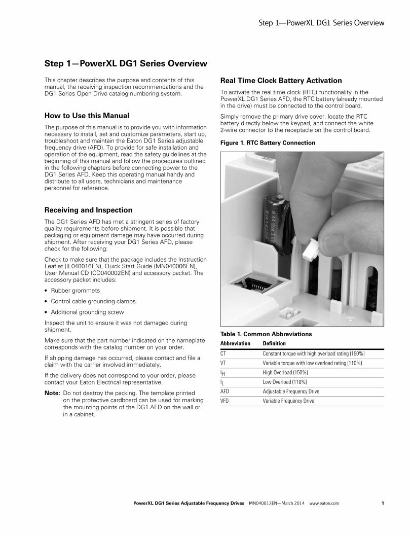
Real Time Clock Battery Activation
To activate the real time clock (RTC) functionality in the PowerXL DG1 Series AFD, the RTC battery (already mounted in the drive) must be connected to the control board.
Simply remove the primary drive cover, locate the RTC battery directly below the keypad, and connect the white 2-wire connector to the receptacle on the control board.
Figure 1. RTC Battery Connection
Table 1. Common Abbreviations
Abbreviation Definition
CT Constant torque with high overload rating (150%)
VT Variable torque with low overload rating (110%)
IH High Overload (150%)
IL Low Overload (110%)
AFD Adjustable Frequency Drive
VFD Variable Frequency Drive
Step 1—PowerXL DG1 Series Overview
2 PowerXL DG1 Series Adjustable Frequency Drives MN040012EN—March 2014 www.eaton.com
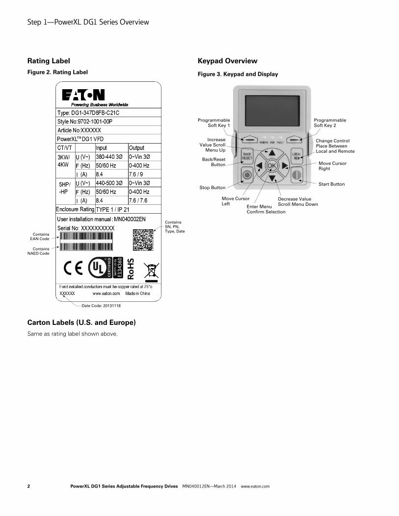
Rating Label
Figure 2. Rating Label
Carton Labels (U.S. and Europe)
Same as rating label shown above.
Keypad Overview
Figure 3. Keypad and Display
ContainsSN, PN,Type, Date
ContainsEAN Code
Date Code: 20131118
ContainsNAED Code
ProgrammableSoft Key 2
Change Control Place Between Local and Remote
Move CursorRight
Start ButtonStop Button
Back/ResetButton
IncreaseValue Scroll
Menu Up
ProgrammableSoft Key 1
Decrease ValueScroll Menu Down
Move Cursor Left
Enter MenuConfirm Selection
Step 2—Keypad Operation Overview
PowerXL DG1 Series Adjustable Frequency Drives MN040012EN—March 2014 www.eaton.com 3
Step 2—Keypad Operation Overview
The keypad is the interface between the drive and the user. It features an LCD display, 3 LED lights and 11 buttons. With the control keypad, it is possible to control the speed of a motor, to supervise the state of the equipment and to set the frequency converter’s parameters. See Figure 3.
Keypad Buttons
Buttons Description
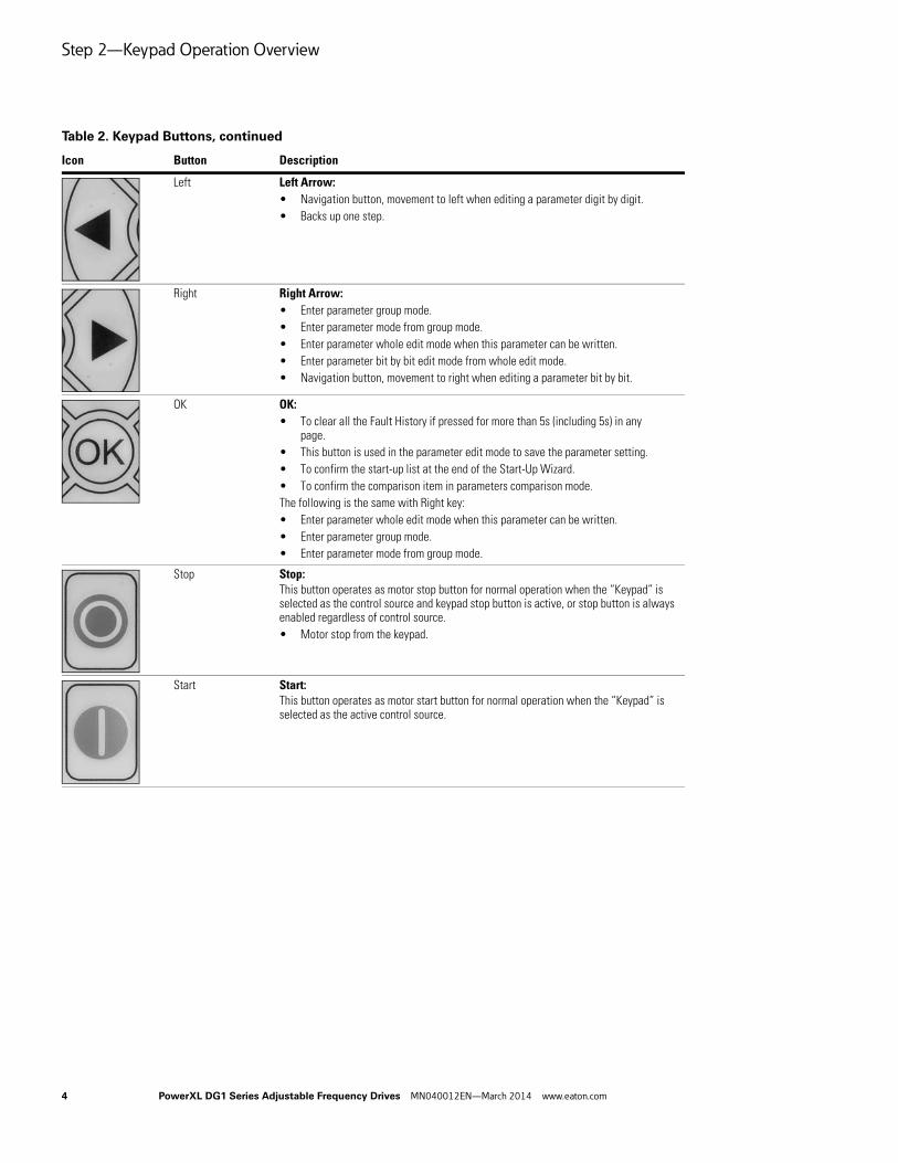
Table 2. Keypad Buttons
Icon Button Description
Soft Key 1, Soft Key 2
Soft Key 1, Soft Key 2:The functions of these two buttons shall be the following:Forward/Reverse, this shall change motor’s run direction.Reset, this shall ask MCU to reset after some parameters are modified.
• Menu, this shall return to main menu.
• Details, this shall display the details of the fault.
• Bypass, this shall make drive go into bypass.
• Jog, this shall activate jog.
• Favorite, this shall add this parameter to the Favorite menu.
• Delete, this shall delete this parameter from the Favorite menu.
Back/Reset Back/Reset:This button has three integrated functions. The button operates as backward button during normal mode. In edit mode, it is used as cancel operate. It is also used to reset faults when faults occur.
• Backs up one step.
• Cancels Modify in edit mode.
• Resets the active faults (all the active faults shall be reset by pressing this button more than 2s in any page).
Local/Remote Local/Remote:Switches between LOCAL and REMOTE control for start and speed reference. The control locations corresponding to local and remote shall be selected within an application.
UpDown
Up and Down Arrows:
• Move either up or down a menu list to select the desired menu item.
• Editing a parameter bit by bit, while the active digit is scrolled.
• Increase/decrease the reference value of the selected parameter.
• In parameter comparison mode, scroll through the parameters of which current value is different from comparison parameter value.
• In parameter page when in read mode, move to the previous or next brother parameter of this parameter.
Step 2—Keypad Operation Overview
4 PowerXL DG1 Series Adjustable Frequency Drives MN040012EN—March 2014 www.eaton.com
Left Left Arrow:
• Navigation button, movement to left when editing a parameter digit by digit.
• Backs up one step.
Right Right Arrow:
• Enter parameter group mode.
• Enter parameter mode from group mode.
• Enter parameter whole edit mode when this parameter can be written.
• Enter parameter bit by bit edit mode from whole edit mode.
• Navigation button, movement to right when editing a parameter bit by bit.
OK OK:
• To clear all the Fault History if pressed for more than 5s (including 5s) in any page.
• This button is used in the parameter edit mode to save the parameter setting.
• To confirm the start-up list at the end of the Start-Up Wizard.
• To confirm the comparison item in parameters comparison mode.
The following is the same with Right key:
• Enter parameter whole edit mode when this parameter can be written.
• Enter parameter group mode.
• Enter parameter mode from group mode.
Stop Stop:This button operates as motor stop button for normal operation when the “Keypad” is selected as the control source and keypad stop button is active, or stop button is always enabled regardless of control source.
• Motor stop from the keypad.
Start Start:This button operates as motor start button for normal operation when the “Keypad” is selected as the active control source.
Table 2. Keypad Buttons, continued
Icon Button Description
Step 2—Keypad Operation Overview
PowerXL DG1 Series Adjustable Frequency Drives MN040012EN—March 2014 www.eaton.com 5
LED Lights
LCD Display
The keypad LCD indicates the status of the motor and the drive and any faults in motor or drive functions. On the LCD, the user sees information about the current location in the menu structure and the item displayed.
Overview
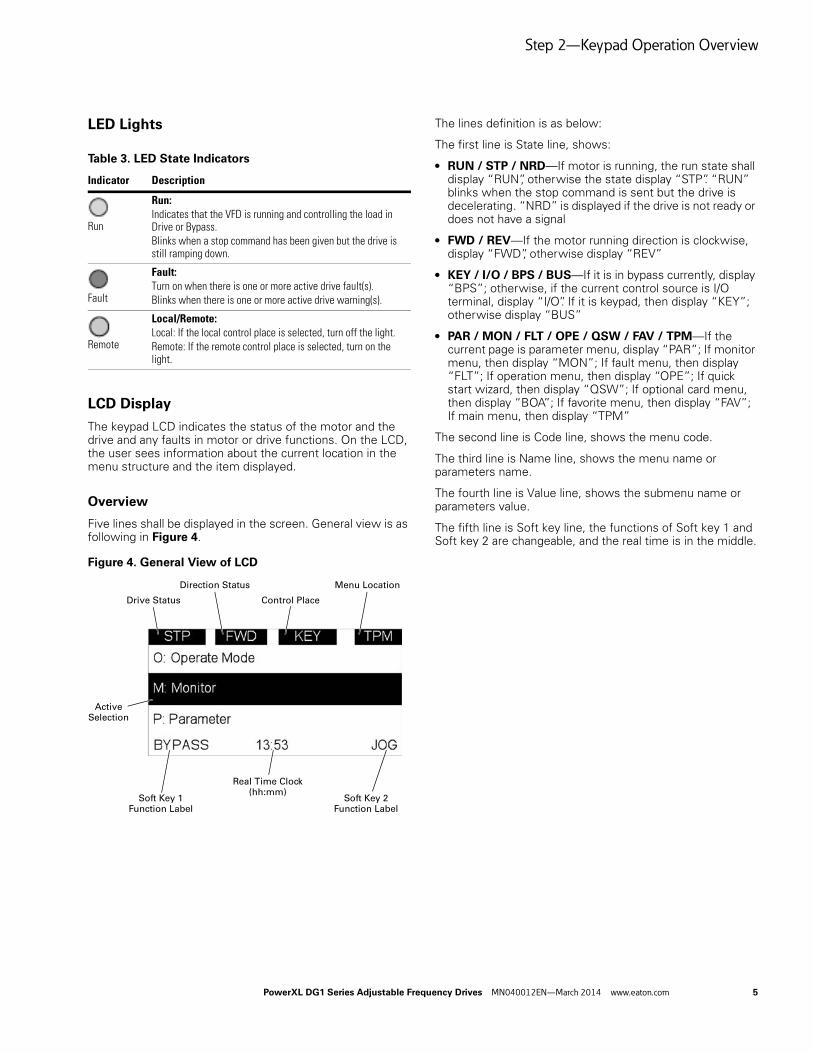
Five lines shall be displayed in the screen. General view is as following in Figure 4.
Figure 4. General View of LCD
The lines definition is as below:
The first line is State line, shows:
● RUN / STP / NRD—If motor is running, the run state shall display “RUN”, otherwise the state display “STP”. “RUN” blinks when the stop command is sent but the drive is decelerating. “NRD” is displayed if the drive is not ready or does not have a signal
● FWD / REV—If the motor running direction is clockwise, display “FWD”, otherwise display “REV”
● KEY / I/O / BPS / BUS—If it is in bypass currently, display “BPS”; otherwise, if the current control source is I/O terminal, display “I/O”. If it is keypad, then display “KEY”; otherwise display “BUS”
● PAR / MON / FLT / OPE / QSW / FAV / TPM—If the current page is parameter menu, display “PAR”; If monitor menu, then display “MON”; If fault menu, then display “FLT”; If operation menu, then display “OPE”; If quick start wizard, then display “QSW”; If optional card menu, then display “BOA”; If favorite menu, then display “FAV”; If main menu, then display “TPM”
The second line is Code line, shows the menu code.
The third line is Name line, shows the menu name or parameters name.
The fourth line is Value line, shows the submenu name or parameters value.
The fifth line is Soft key line, the functions of Soft key 1 and Soft key 2 are changeable, and the real time is in the middle.
Table 3. LED State Indicators
Indicator Description
Run
Run:Indicates that the VFD is running and controlling the load in Drive or Bypass. Blinks when a stop command has been given but the drive is still ramping down.
Fault
Fault:Turn on when there is one or more active drive fault(s). Blinks when there is one or more active drive warning(s).
Remote
Local/Remote:Local: If the local control place is selected, turn off the light.Remote: If the remote control place is selected, turn on the light.
Drive Status
Direction Status
Control Place
Menu Location
Soft Key 2Function Label
Soft Key 1Function Label
Real Time Clock(hh:mm)
ActiveSelection
Step 3—Menu Navigation
6 PowerXL DG1 Series Adjustable Frequency Drives MN040012EN—March 2014 www.eaton.com
Step 3—Menu Navigation
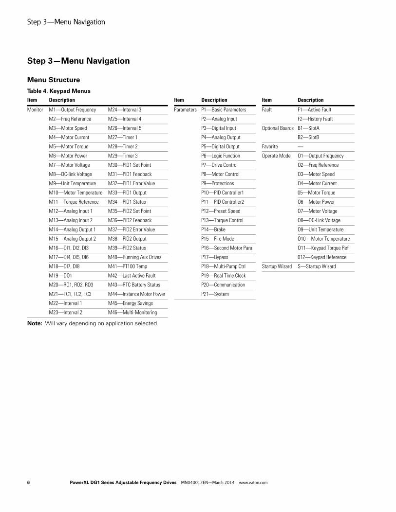
Menu Structure
Table 4. Keypad Menus
Note: Will vary depending on application selected.
M20—RO1, RO2, RO3 M43—RTC Battery Status P20—Communication
M21—TC1, TC2, TC3 M44—Instance Motor Power P21—System
M22—Interval 1 M45—Energy Savings
M23—Interval 2 M46—Multi-Monitoring
Step 3—Menu Navigation
PowerXL DG1 Series Adjustable Frequency Drives MN040012EN—March 2014 www.eaton.com 7
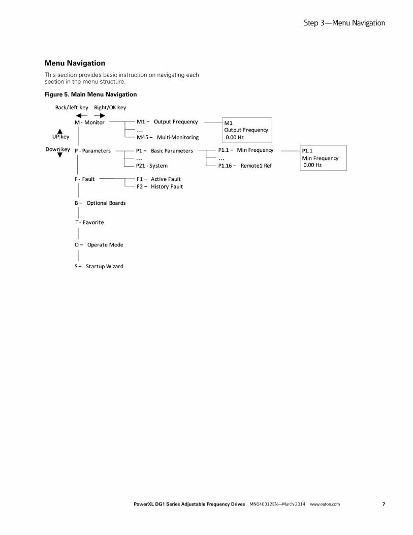
Menu Navigation
This section provides basic instruction on navigating each section in the menu structure.
Figure 5. Main Menu Navigation
Step 4—Startup Wizard
8 PowerXL DG1 Series Adjustable Frequency Drives MN040012EN—March 2014 www.eaton.com
Step 4—Startup Wizard
Startup Wizard
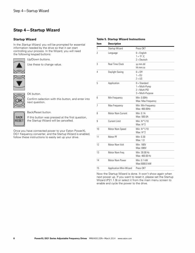
In the Startup Wizard, you will be prompted for essential information needed by the drive so that it can start controlling your process. In the Wizard, you will need the following keypad buttons:
Up/Down buttons.
Use these to change value.
OK button.
Confirm selection with this button, and enter into next question.
Back/Reset button.
If this button was pressed at the first question, the Startup Wizard will be cancelled.
Once you have connected power to your Eaton PowerXL DG1 frequency converter, and the Startup Wizard is enabled, follow these instructions to easily set up your drive.
Table 5. Startup Wizard Instructions
Now the Startup Wizard is done. It won’t show again when next power up. If you want to reset it, please set the Startup Wizard (P21.1.9) or select it from the main menu screen to enable and cycle the power to the drive.
PowerXL DG1 Series Adjustable Frequency Drives MN040012EN—March 2014 www.eaton.com 9
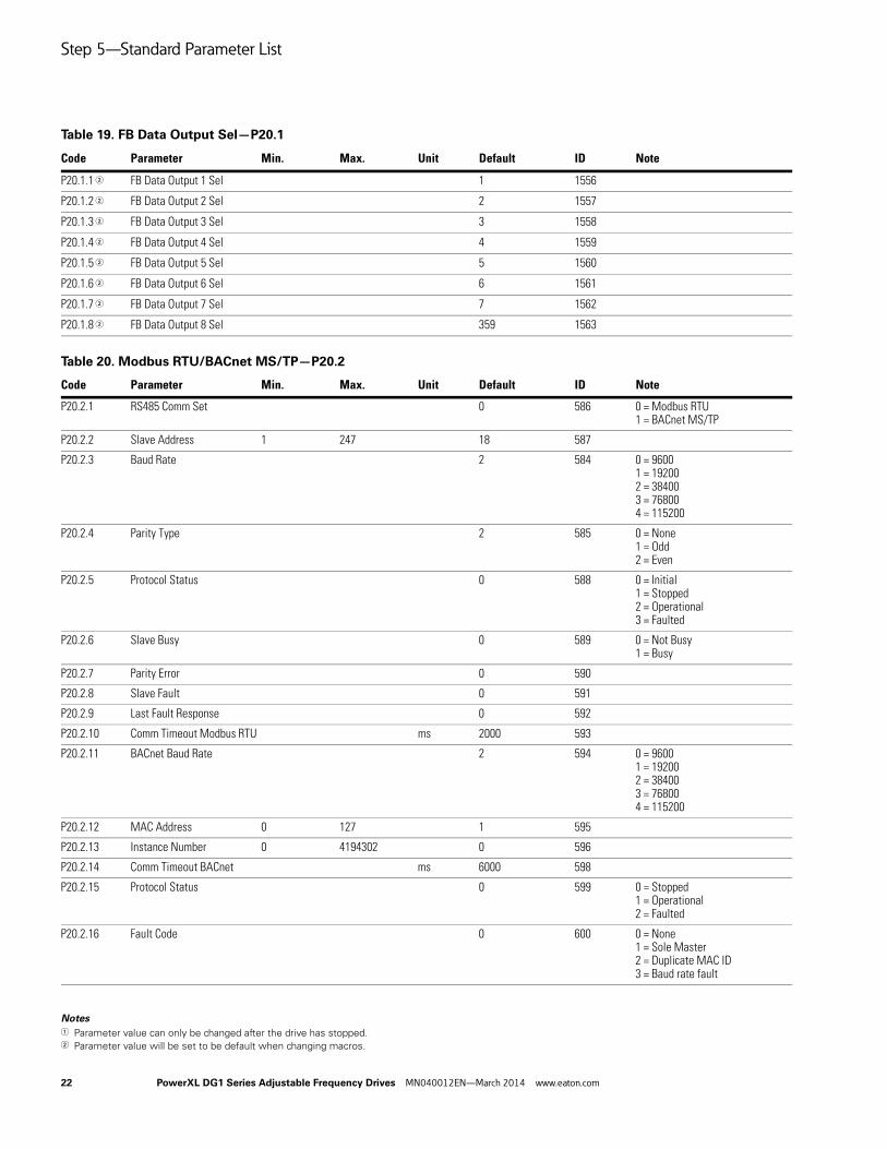
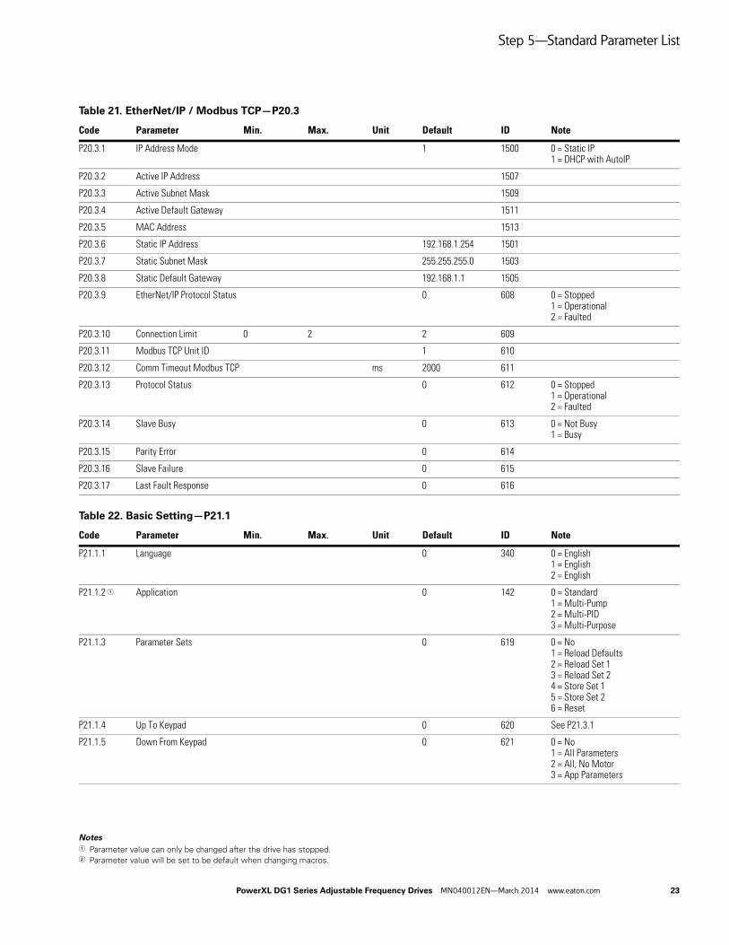
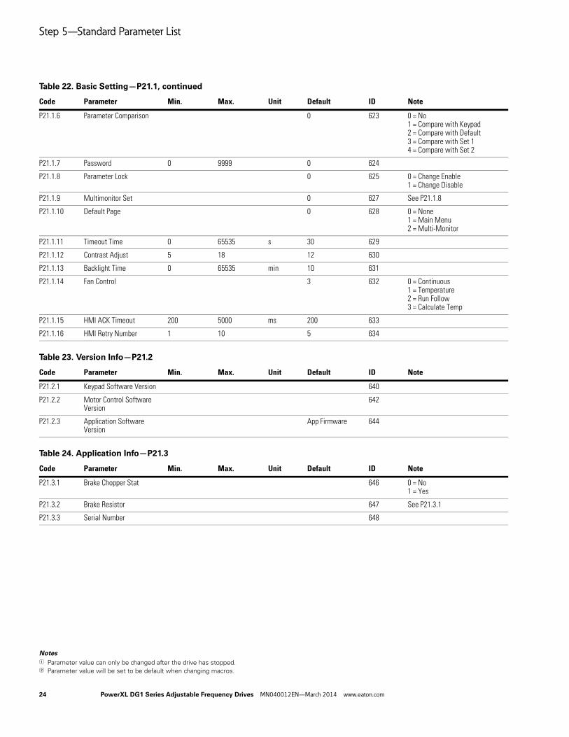
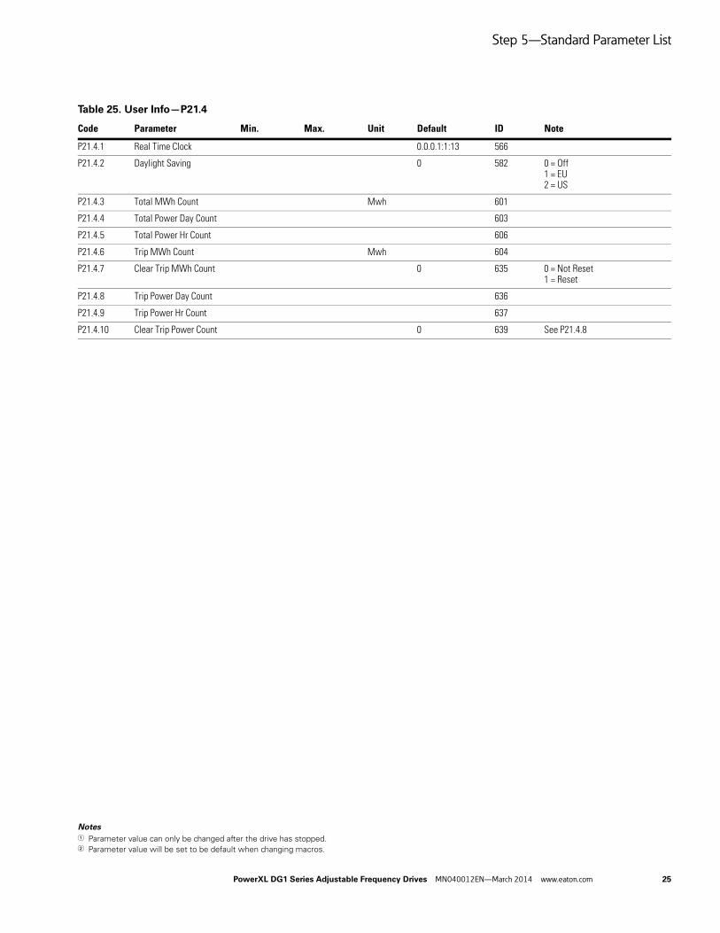
Step 5—Standard Parameter List
Introduction
The Standard Application is typically used in basic motor control scenarios where multiple pump control, PID loops, or advanced control loops are not required. It provides the ability for the user to define its local and remote control and reference signals. In addition there is the ability to scale the analog input and output signals to be read based off the desired motor response. There are also 8 digital inputs, 3 relay outputs, and 1 digital output that can be programmed to allow for control schemes that require the drive to have certain functions. It provides full customization on the motor control sequence with the ability to be in frequency or speed control mode, and tuning of the V/Hz curve can be selected. Drive/Motor protections can be customized to defined actions for added user control. Below is a list of other features that are available in the Standard Application.
Standard Application includes functions:
● Selectable digital input function
● Selectable digital output function
● Reference filter, scaling, inversion, offset and range
● Output signal filter, scaling, inversion, offset and range
● Selectable analog output function
● Programmable start/stop and reverse signal logic
● Two independent set of Acceleration/Deceleration ramps
● S curves
● Skip frequency
● Start source (Local/Remote control function)
● Reference source
● Flying start
● Jog
● Volts per Hertz control
● Real time clock function—RTC time display
● Drive temperature limit supervision
● Output frequency 1 limit supervision
● Output frequency 2 limit supervision
● Torque limit supervision
● Reference frequency limit supervision
● Power limit supervision
● Analog input limit supervision
● Auto restart
● Power loss ride through
● Trend buffer
● Programmable switching frequency
● Multi-Preset speeds
● Emergency stop
● Line start lockout
● Fan control
● DC brake
● Flux brake
● Dynamic brake
I/O Controls● “Terminal To Function” (TTF) Programming
The design behind the programming of the digital inputs in the DG1 drive is to use “Terminal To Function” programming, which is composed of multiple functions that get assigned a digital input to that function. The parameters in the drive are set up with specific functions and by defining the digital input and slot in some cases, depending on which options are available. For use of the drives control board inputs, they will be referred to as DigIN:1 through DigIN:8. When additional option cards are used, they will be defined as DigIN:X:IOY:Z. The X indicates the slot that the card is being installed in, which will be either A or B. The IOY determines the type of card it is, which would be IO1 or IO5. The Z indicates which input is being used on that available option card.
● “Function To Terminal” (FTT) Programming
The design behind the programming of the relay outputs and digital output in the DG1 drive is to use “Function To Terminal” programming. It is composed of a terminal, be it a relay output or a digital output, that is assigned a parameter. Within that parameter, it has different functions that can be set.
The parameters of the Standard Application are explained on Page 11 of this manual, “Description of Parameters.” The explanations are arranged according to the parameter number.
Step 5—Standard Parameter List
10 PowerXL DG1 Series Adjustable Frequency Drives MN040012EN—March 2014 www.eaton.com
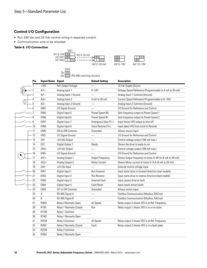
Control I/O Configuration● Run 240 Vac and 24 Vdc control wiring in separate conduit ● Communication wire to be shielded
Table 6. I/O Connection
Pin Signal Name Signal Default Setting Description
1 +10V Ref. Output Voltage — 10 Vdc Supply Source
2 AI1+ Analog Input 1 0–10V Voltage Speed Reference (Programmable to 4 mA to 20 mA)
3 AI1– Analog Input 1 Ground — Analog Input 1 Common (Ground)
4 AI2+ Analog Input 2 4 mA to 20 mA Current Speed Reference (Programmable to 0–10V)
5 AI2– Analog Input 2 Ground — Analog Input 2 Common (Ground)
6 GND I/O Signal Ground — I/O Ground for Reference and Control
7 DIN5 Digital Input 5 Preset Speed B0 Sets frequency output to Preset Speed 1
8 DIN6 Digital Input 6 Preset Speed B1 Sets frequency output to Preset Speed 2
9 DIN7 Digital Input 7 Emergency Stop (TI–) Input forces VFD output to shut off
10 DIN8 Digital Input 8 Force Remote (TI+) Input takes VFD from Local to Remote
11 CMB DI5 to DI8 Common Grounded Allows source input
12 GND I/O Signal Ground — I/O Ground for Reference and Control
13 24V +24 Vdc Output — Control voltage output (100 mA max.)
14 DO1 Digital Output 1 Ready Shows the drive is ready to run
15 24Vo +24 Vdc Output — Control voltage output (100 mA max.)
16 GND I/O Signal Ground — I/O Ground for Reference and Control
17 AO1+ Analog Output 1 Output Frequency Shows Output frequency to motor 0–60 Hz (4 mA to 20 mA)
18 AO2+ Analog Output 2 Motor Current Shows Motor current of motor 0–FLA (4 mA to 20 mA)
19 24Vi +24 Vdc Input — External control voltage input
20 DIN1 Digital Input 1 Run Forward Input starts drive in forward direction (start enable)
21 DIN2 Digital Input 2 Run Reverse Input starts drive in reverse direction (start enable)
22 DIN3 Digital Input 3 External Fault Input causes drive to fault
23 DIN4 Digital Input 4 Fault Reset Input resets active faults
24 CMA DI1 to DI4 Common Grounded Allows source input
25 A RS-485 Signal A — Fieldbus Communication (Modbus, BACnet)
26 B RS-485 Signal B — Fieldbus Communication (Modbus, BACnet)
27 R3NO Relay 3 Normally Open At Speed Relay output 3 shows VFD is at Ref. Frequency
28 R1NC Relay 1 Normally Closed Run Relay output 1 shows VFD is in a run state
29 R1CM Relay 1 Common
30 R1NO Relay 1 Normally Open
31 R3CM Relay 3 Common At Speed Relay output 3 shows VFD is at Ref. Frequency
32 R2NC Relay 2 Normally Closed Fault Relay output 2 shows VFD is in a fault state
33 R2CM Relay 2 Common
34 R2NO Relay 2 Normally Open
SW2
AI2 0–20 mA AI2 0–10V
AI2 0–20 mA
SW1AI1 0–10V
AI2 SW2
On
AI2 SW1
Off (RS-485 matching resistor)
AI2 10–10V
Res
i
Step 5—Standard Parameter List
PowerXL DG1 Series Adjustable Frequency Drives MN040012EN—March 2014 www.eaton.com 11
Notes1 Parameter value can only be changed after the drive has stopped.2 Parameter value will be set to be default when changing macros.
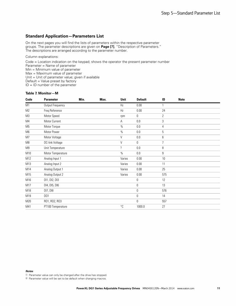
Standard Application—Parameters List
On the next pages you will find the lists of parameters within the respective parameter groups. The parameter descriptions are given on Page [?], “Description of Parameters.” The descriptions are arranged according to the parameter number.
Column explanations:
Code = Location indication on the keypad; shows the operator the present parameter numberParameter = Name of parameterMin = Minimum value of parameterMax = Maximum value of parameterUnit = Unit of parameter value; given if availableDefault = Value preset by factoryID = ID number of the parameter
Table 7. Monitor—M
Code Parameter Min. Max. Unit Default ID Note
M1 Output Frequency Hz 0.00 1
M2 Freq Reference Hz 0.00 24
M3 Motor Speed rpm 0 2
M4 Motor Current A 0.0 3
M5 Motor Torque % 0.0 4
M6 Motor Power % 0.0 5
M7 Motor Voltage V 0.0 6
M8 DC-link Voltage V 0 7
M9 Unit Temperature ? 0.0 8
M10 Motor Temperature % 0.0 9
M12 Analog Input 1 Varies 0.00 10
M13 Analog Input 2 Varies 0.00 11
M14 Analog Output 1 Varies 0.00 25
M15 Analog Output 2 Varies 0.00 575
M16 DI1, DI2, DI3 0 12
M17 DI4, DI5, DI6 0 13
M18 DI7, DI8 0 576
M19 DO1 0 14
M20 RO1, RO2, RO3 0 557
M41 PT100 Temperature °C 1000.0 27
Step 5—Standard Parameter List
12 PowerXL DG1 Series Adjustable Frequency Drives MN040012EN—March 2014 www.eaton.com
Notes1 Parameter value can only be changed after the drive has stopped.2 Parameter value will be set to be default when changing macros.
M42 Last Active Fault 0 28 0 = Null1 = Over Current2 = Over Voltage3 = Earth Fault4 = Charging Switch5 = Emergency Stop6 = Saturation Trip7 = System Fault8 = Undervoltage9 = Input Phase Superv10 = Output Phase Superv11 = Brake Chopper Superv12 = Drive Under Temp13 = Drive Over Temp14 = Motor Stalled15 = Motor Over Temp16 = Motor Under Load17 = IP Address Conflict18 = Power Board EEPROM Fault19 = FRAM Fault20 = S-Flash Fault21 = MCU Watchdog Fault22 = Start-up Prevent23 = Thermistor Fault24 = Fan Cooling25 = Compatibility Fault26 = Device Change27 = Device Added28 = Device Removed29 = Device Unknown30 = IGBT Over Temp31 = Encoder Fault32 = AI < 4 mA (4to20 mA)33 = External Fault34 = Keypad Comm Fault35 = Fieldbus Fault36 = Option Card Fault37 = Bypass Overload38 = Realtime Clock Fault39 = PT100 Fault40 = Motor ID Fault41 = Current Measure Fault42 = Power Wiring Error43 = Control Board Overtemp44 = Internal Control Supply45 = Speed Search Fault46 = Current Unbalance47 = Replace Battery48 = Replace Fan49 = Safety Torque Off50 = Current Limit Controller51 = Over Voltage Controller
M43 RTC Battery Status 583 0 = Not Installed1 = Installed2 = Change Battery3 = Over Voltage
M44 Instance Motor Power kW 0.00 1686
M45 Energy Savings Varies 2119
M46 Multi-Monitoring 1, 2, 3 30
Table 7. Monitor—M, continued
Code Parameter Min. Max. Unit Default ID Note
Step 5—Standard Parameter List
PowerXL DG1 Series Adjustable Frequency Drives MN040012EN—March 2014 www.eaton.com 13
Notes1 Parameter value can only be changed after the drive has stopped.2 Parameter value will be set to be default when changing macros.
16 PowerXL DG1 Series Adjustable Frequency Drives MN040012EN—March 2014 www.eaton.com
Notes1 Parameter value can only be changed after the drive has stopped.2 Parameter value will be set to be default when changing macros.
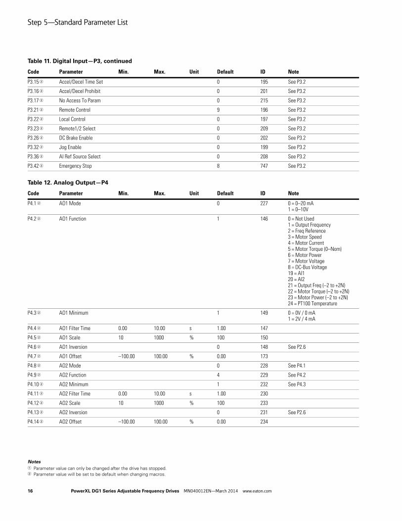
P3.15 2 Accel/Decel Time Set 0 195 See P3.2
P3.16 2 Accel/Decel Prohibit 0 201 See P3.2
P3.17 2 No Access To Param 0 215 See P3.2
P3.21 2 Remote Control 9 196 See P3.2
P3.22 2 Local Control 0 197 See P3.2
P3.23 2 Remote1/2 Select 0 209 See P3.2
P3.26 2 DC Brake Enable 0 202 See P3.2
P3.32 2 Jog Enable 0 199 See P3.2
P3.36 2 AI Ref Source Select 0 208 See P3.2
P3.42 2 Emergency Stop 8 747 See P3.2
Table 12. Analog Output—P4
Code Parameter Min. Max. Unit Default ID Note
P4.1 2 AO1 Mode 0 227 0 = 0–20 mA1 = 0–10V
P4.2 2 AO1 Function 1 146 0 = Not Used1 = Output Frequency2 = Freq Reference3 = Motor Speed4 = Motor Current5 = Motor Torque (0–Nom)6 = Motor Power7 = Motor Voltage8 = DC-Bus Voltage19 = AI120 = AI221 = Output Freq (–2 to +2N)22 = Motor Torque (–2 to +2N)23 = Motor Power (–2 to +2N)24 = PT100 Temperature
26 PowerXL DG1 Series Adjustable Frequency Drives MN040012EN—March 2014 www.eaton.com
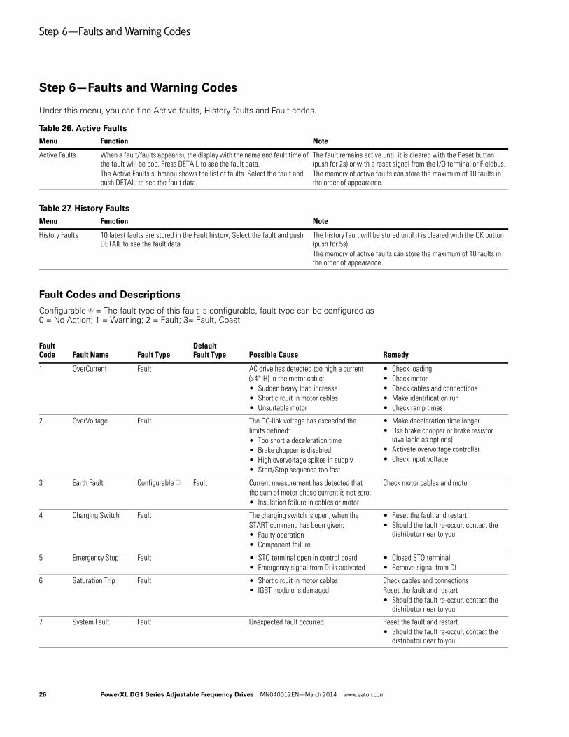
Step 6—Faults and Warning Codes
Under this menu, you can find Active faults, History faults and Fault codes.
Table 26. Active Faults
Table 27. History Faults
Fault Codes and Descriptions
Configurable 1 = The fault type of this fault is configurable, fault type can be configured as 0 = No Action; 1 = Warning; 2 = Fault; 3= Fault, Coast
Menu Function Note
Active Faults When a fault/faults appear(s), the display with the name and fault time of the fault will be pop. Press DETAIL to see the fault data. The Active Faults submenu shows the list of faults. Select the fault and push DETAIL to see the fault data.
The fault remains active until it is cleared with the Reset button (push for 2s) or with a reset signal from the I/O terminal or Fieldbus.The memory of active faults can store the maximum of 10 faults in the order of appearance.
Menu Function Note
History Faults 10 latest faults are stored in the Fault history, Select the fault and push DETAIL to see the fault data.
The history fault will be stored until it is cleared with the OK button (push for 5s).The memory of active faults can store the maximum of 10 faults in the order of appearance.
Fault Code Fault Name Fault Type
Default Fault Type Possible Cause Remedy
1 OverCurrent Fault AC drive has detected too high a current(>4*IH) in the motor cable:• Sudden heavy load increase• Short circuit in motor cables• Unsuitable motor
• Check loading• Check motor• Check cables and connections• Make identification run• Check ramp times
2 OverVoltage Fault The DC-link voltage has exceeded thelimits defined:• Too short a deceleration time• Brake chopper is disabled• High overvoltage spikes in supply• Start/Stop sequence too fast
• Make deceleration time longer• Use brake chopper or brake resistor
(available as options)• Activate overvoltage controller• Check input voltage
3 Earth Fault Configurable 1 Fault Current measurement has detected thatthe sum of motor phase current is not zero:• Insulation failure in cables or motor
Check motor cables and motor
4 Charging Switch Fault The charging switch is open, when theSTART command has been given:• Faulty operation• Component failure
• Reset the fault and restart• Should the fault re-occur, contact the
distributor near to you
5 Emergency Stop Fault • STO terminal open in control board• Emergency signal from DI is activated
• Closed STO terminal• Remove signal from DI
6 Saturation Trip Fault • Short circuit in motor cables• IGBT module is damaged
Check cables and connectionsReset the fault and restart• Should the fault re-occur, contact the
distributor near to you
7 System Fault Fault Unexpected fault occurred Reset the fault and restart.• Should the fault re-occur, contact the
distributor near to you
Step 6—Faults and Warning Codes
PowerXL DG1 Series Adjustable Frequency Drives MN040012EN—March 2014 www.eaton.com 27
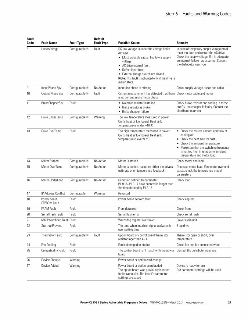
8 UnderVoltage Configurable 1 Fault DC link voltage is under the voltage limitsdefined:• Most probable cause: Too low a supply
voltage• AC drive internal fault• Defect input fuse• External charge switch not closedNote: This fault is activated only if the drive is in Run state.
In case of temporary supply voltage break reset the fault and restart the AC drive Check the supply voltage. If it is adequate, an internal failure has occurred. Contact the distributor near you
9 Input Phase Spv Configurable 1 No Action Input line phase is missing Check supply voltage, fuses and cable
10 Output Phase Spv Configurable 1 Fault Current measurement has detected that there is no current in one motor phase
Check motor cable and motor
11 BrakeChopperSpv Fault • No brake resistor installed• Brake resistor is broken• Brake chopper failure
Check brake resistor and cabling. If these are OK, the chopper is faulty. Contact the distributor near you
12 Drive UnderTemp Configurable 1 Warning Too low temperature measured in powerUnit’s heat sink or board. Heat sink temperature is under –10°C
13 Drive OverTemp Fault Too high temperature measured in powerUnit’s heat sink or board. Heat sink temperature is over 90°C
• Check the correct amount and flow of cooling air
• Check the heat sink for dust• Check the ambient temperature• Make sure that the switching frequency
is not too high in relation to ambient temperature and motor load
14 Motor Stalled Configurable 1 No Action Motor is stalled Check motor and load
15 Motor OverTemp Configurable 1 No Action Motor is too hot, based on either the drive’s estimate or on temperature feedback
Decrease motor load. If no motor overload exists, check the temperature model parameters
16 Motor UnderLoad Configurable 1 No Action Condition defined by parameter P1.9.15~P1.9.17 have been valid longer than the time defined by P1.9.18
Check load
17 IP Address Conflict Configurable Warning Reversed
18 Power board EEPROM Fault
Fault Power board eeprom fault Check eeprom
19 FRAM Fault Fault Fram data error Check fram
20 Serial Flash Fault Fault Serial flash error Check serial flash
21 MCU Watchdog Fault Fault Watchdog register overflows Power cycle unit
22 Start-up Prevent Fault The time when Interlock signal activates is over setting time
Stop drive
23 Thermistor Fault Configurable 1 Fault Option board or control board thermistor resistor lager than 4.7K
Thermistor open or short, over temperature
24 Fan Cooling Fault Fan is damaged or stalled Check fan and fan connected wires
25 Compatibility Fault Fault The control board isn’t match with the power board
Contact the distributor near you
26 Device Change Warning Power board or option card change
27 Device Added Warning Power board or option board addedThe option board was previously inserted in the same slot. The board’s parameter settings are saved
Device is ready for useOld parameter settings will be used
Fault Code Fault Name Fault Type
Default Fault Type Possible Cause Remedy
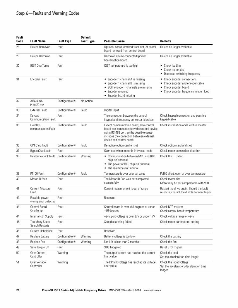
Step 6—Faults and Warning Codes
28 PowerXL DG1 Series Adjustable Frequency Drives MN040012EN—March 2014 www.eaton.com
28 Device Removed Fault Optional board removed from slot, or power board removed from control board
30 IGBT OverTemp Fault IGBT temperature is too high • Check loading• Check motor size• Decrease switching frequency
31 Encoder Fault Fault • Encoder 1 channel A is missing • Encoder 1 channel B is missing• Both encoder 1 channels are missing• Encoder reversed• Encoder board missing
• Check encoder connections• Check encoder and encoder cable• Check encoder board• Check encoder frequency in open loop
32 AIN<4 mA (4 to 20 mA
Configurable 1 No Action
33 External Fault Configurable 1 Fault Digital input
34 Keypad Communication Fault
Fault The connection between the controlkeypad and frequency converter is broken
Check keypad connection and possible keypad cable
35 FieldBus communication Fault
Configurable 1 Fault Except communication board, also control board can communicate with external device using RS-485 port, so the possible cause includes the connection between external device and control board
Check installation and Fieldbus master
36 OPT Card Fault Configurable 1 Fault Defective option card or slot Check option card and slot
37 BypassOverLoad Fault Over load when motor is in bypass mode Check motor connection situation
38 Real time clock fault Configurable 1 Warning • Communication between MCU and RTC chip isn’t normal
• The power of RTC chip isn’t normal• The real time isn’t normal
Check the RTC chip
39 PT100 Fault Configurable 1 Fault Temperature is over user set value Pt100 short, open or over temperature
40 Motor ID fault Fault The Motor ID Run was not completed successfully
Check motor sizeMotor may be not compactable with VFD
41 Current Measure Fault
Fault Current measurement is out of range Restart the drive again. Should the fault re-occur, contact the distributor near to you
42 Possible power wiring error detected
Fault Reserved
43 Control Board OverTemp
Fault Control board is over +85 degrees or under –30 degrees
Check NTC resistorCheck control board temperature
44 Internal-ctrl Supply Fault +24V port voltage is over 27V or under 17V Check voltage range of +24V
45 Too Many Speed Search Restarts
Fault Speed searching failed Check motor parameters’ setting
46 Current Unbalance Fault Reserved
47 Replace Battery Configurable 1 Warning Battery voltage is too low Check the battery
48 Replace Fan Configurable 1 Warning Fan life is less than 2 months Check the fan
49 Safe Torque Off Fault STO Triggered Reset STO Trigger
50 Over Current Controller
Warning The output current has reached the current limit value
Check the loadSet the acceleration time longer
51 Over Voltage Controller
Warning The DC link voltage has reached its voltage limit value
Check the input voltageSet the acceleration/deceleration time longer
Fault Code Fault Name Fault Type
Default Fault Type Possible Cause Remedy
Eaton is a registered trademark.
All other trademarks are property of their respective owners.
Eaton is dedicated to ensuring that reliable, efficient and safe power is available when it’s needed most. With unparalleled knowledge of electrical power management across industries, experts at Eaton deliver customized, integrated solutions to solve our customers’ most critical challenges.
Our focus is on delivering the right solution for the application. But, decision makers demand more than just innovative products. They turn to Eaton for an unwavering commitment to personal support that makes customer success a top priority. For more information, visit www.eaton.com/electrical.
Eaton1000 Eaton BoulevardCleveland, OH 44122 United StatesEaton.com