172
Manual PowerXL ™ Titel DC1-S… Variable Frequency Drives for single-phase AC motors Installation and Parameter Manual 09/16 MN040028EN
Manual 09/16 MN040028EN
PowerXL™
Titel
DC1-S…
Variable Frequency Drives for single-phase AC motors
Installation and Parameter Manual
All proprietary names and product designations are brand names or trademarks registered to the relevant title holders.
Break-Down ServicePlease call your local representative:http://eaton.com/moeller/aftersalesorHotline After Sales Service:+49 (0) 180 5 223822 (de, en)[email protected]
For customers in US/Canada contact:
EatonCare Customer Support Center
Call the EatonCare Support Center if you need assistance with placing an order, stock availability or proof of shipment, expediting an existing order, emergency shipments, product price information, returns other than warranty returns, and information on local distributors or sales offices.
Voice: 877-ETN-CARE (386-2273) (8:00 a.m. – 6:00 p.m. EST)After-Hours Emergency: 800-543-7038 (6:00 p.m. – 8:00 a.m. EST)
Drives Technical Resource Center
Voice: 877-ETN-CARE (386-2273) option 2, option 6(8:00 a.m. – 5:00 p.m. Central Time U.S. [UTC-6])email: [email protected]/drives
Original operating manualThe German-language edition of this document is the original operating manual.
Translation of the original operating manualAll editions of this document other than those in German language are translations of the original operating manual.
1. Edition 2016, publication date 09/16© 2016 by Eaton Industries GmbH, 53105 Bonn
Authors: Jörg Randermann, Heribert JoachimRedaction: René Wiegand
All rights reserved, also for the translation.
No part of this manual may be reproduced, stored in a retrieval system, or transmitted in any form or by any means, electronic, mechanical, photocopying, micro-filming, recording or otherwise, without the prior written permission of Eaton Industries GmbH, Bonn.
Subject to alteration.
Eato
n In
dust
ries
Gm
bHS
afet
y in
stru
ctio
nsDanger!Dangerous electrical voltage!
Before commencing the installation
• Disconnect the power supply of the device.
• Ensure that devices cannot be accidentally retriggered.
• Verify isolation from the supply.
• Ground and short-circuit.
• Cover or enclose neighbouring units that are live.
• Follow the engineering instructions (IL) of the device concerned.
• Only suitably qualified personnel in accordance with EN 50110-1/-2 (VDE 0105 Part 100) may work on this device/system.
• Before installation and before touching the device ensure that you are free of electrostatic charge.
• The functional earth (FE) must be connected to the protective earth (PE) or to the potential equalizing.The system installer is responsible for implementing this connection.
• Connecting cables and signal lines should be installed so that inductive or capacitive interference do not impair the automation functions.
• Install automation devices and related operating elements in such a way that they are well protected against uninten-tional operation.
• Suitable safety hardware and software measures should be implemented for the I/O connection so that a cable or wire breakage on the signal side does not result in undefined states in the automation device.
• Ensure a reliable electrical isolation of the low voltage for the 24 V supply. Only use power supply units complying with IEC 60364-4-41 or HD 384.4.41 S2 (VDE 0100 part 410).
• Deviations of the mains voltage from the nominal value must not exceed the tolerance limits given in the technical data, otherwise this may cause malfunction and dangerous operation.
• Emergency-Stop devices complying with IEC/EN 60204-1 must be effective in all operating modes of the automation devices. Unlatching the emergency switching off devices must not cause restart.
• Built-in devices for enclosures or cabinets must only be run and operated in an installed state, desk-top devices or portable devices only when the housing is closed.
• Measures should be taken to ensure the proper restart of programs interrupted after a voltage dip or failure. This should not cause dangerous operating states even for a short time. If necessary, emergency switching off devices should be implemented.
• Wherever faults in the automation system may cause damage to persons or property, external measures must be implemented to ensure a safe operating state in the event of a fault or malfunction (for example, by means of separate limit switches, mechanical interlocks, etc.).
• During operation, and depending on their degree of protection, variable frequency drives may have live, uninsulated, moving, and/or rotating parts, as well as hot surfaces.
• The impermissible removal of the required cover, improper installation or incorrect operation of the motor or variable frequency drive can cause the failure of the device and serious injury and/or material damage.
• Comply with all applicable national accident prevention regulations (e.g. BGV A3) when working with energized variable frequency drives.
• The electrical installation must be carried out in accordance with the relevant regulations (e.g. with regard to cable cross sections, fuses, PE).
• All transport, installation, commissioning and mainte-nance work must only be carried out by trained personnel (observe IEC 60364, HD 384 or DIN VDE 0100 and national accident prevention regulations).
• If applicable, systems in which variable frequency drives are installed must be equipped with additional monitoring and protective devices in accordance with the applicable safety regulations, e.g., the German Equipment and Product Safety Act, accident prevention regulations, etc. Making changes to the variable frequency drives by using the operating software is allowed.
• Keep all covers and doors closed during operation.
• When designing the machine, the user must incorporate mechanisms and measures that limit the consequences of a drive controller malfunction or failure (an increase in motor speed or the motor?9s sudden stop) so as to prevent hazards to people and property, e.g.:
– Additional stand-alone devices for monitoring parame-ters that are relevant to safety (speed, travel, end positions, etc.)
– Electrical and non-electrical safety devices (interlocks or mechanical locks) for mechanisms that protect the entire system
– Due to the possibility of there being capacitors that are still holding a charge, do not touch live device parts or terminals immediately after disconnecting the variable frequency drives from the supply voltage. Heed the corresponding labels on the variable frequency drives
Table of contents
0 About this manual ..................................................................... 5
0.1 Target group................................................................................. 5
0.2 List of revisions ............................................................................ 50.2.1 Writing conventions ..................................................................... 60.2.2 Hazard warnings of material damages ......................................... 60.2.3 Hazard warnings of personal injury .............................................. 60.2.4 Tips............................................................................................... 6
0.3 Documents with additional information ....................................... 7
0.4 Abbreviations ............................................................................... 7
0.5 Mains supply voltages.................................................................. 8
0.6 Units of measurement ................................................................. 8
1 Device series DC1-S…................................................................ 9
1.1 Introduction .................................................................................. 9
1.2 System overview ......................................................................... 10
1.3 Checking the Delivery .................................................................. 11
1.4 Rated operational data ................................................................. 121.4.1 Rated operational data on the nameplate .................................... 121.4.2 Key to part numbers..................................................................... 141.4.3 Features ....................................................................................... 15
1.5 Description ................................................................................... 171.5.1 IP20 degree of protection ............................................................ 171.5.2 IP66 degree of protection ............................................................ 18
1.6 Voltage categories........................................................................ 19
1.7 Selection Criteria .......................................................................... 20
1.8 Output reduction (derating) .......................................................... 21
1.9 Proper use.................................................................................... 23
1.10 Maintenance and inspection ........................................................ 24
1.11 Storage......................................................................................... 24
1.12 Charging the internal DC link capacitors ...................................... 25
1.13 Service and warranty.................................................................... 25
2 Engineering................................................................................. 27
2.1 Introduction .................................................................................. 27
2.2 Electrical power network ............................................................. 292.2.1 Mains terminal and configuration................................................. 292.2.2 Mains voltage and frequency ....................................................... 302.2.3 Reactive power compensation devices ....................................... 30
2.3 Cable cross-sections .................................................................... 30
DC1-S… Variable Frequency Drives 09/16 MN040028EN www.eaton.com 1
2.4 Safety and switching.................................................................... 312.4.1 Disconnecting device................................................................... 312.4.2 Fuses ........................................................................................... 322.4.3 Residual current circuit-breaker (RCD) ......................................... 322.4.4 Mains contactors ......................................................................... 33
2.5 Mains chokes............................................................................... 34
2.6 Radio interference suppression filter ........................................... 35
2.7 Braking resistances...................................................................... 36
2.8 Switching to the output side........................................................ 382.8.1 Contactors.................................................................................... 382.8.2 switch-disconnectors ................................................................... 38
2.9 Single-phase AC motors .............................................................. 392.9.1 Split pole motor............................................................................ 402.9.2 Split-phase motors ....................................................................... 412.9.3 Capacitor-start/induction-run motors............................................ 422.9.4 Capacitor motor (PSC-Motor)....................................................... 422.9.5 Capacitor-start/capacitor-run motors............................................ 432.9.6 Three-phase motors run from a single-phase supply
(Steinmetz connection) ................................................................ 442.9.7 Motor Selection ........................................................................... 452.9.8 Connecting EX motors ................................................................. 45
3 Installation.................................................................................. 47
3.1 Introduction.................................................................................. 47
3.2 Mounting position........................................................................ 47
3.3 Mounting ..................................................................................... 483.3.1 Mounting position........................................................................ 493.3.2 Cooling measures ........................................................................ 493.3.3 Fixing ........................................................................................... 51
3.4 IP66 / NEMA4X degree of protection .......................................... 54
3.5 EMC installation........................................................................... 553.5.1 EMC measures in the control panel............................................. 553.5.2 Grounding .................................................................................... 573.5.3 Internal filters (EMC and VAR screws)......................................... 583.5.4 Screen earth kit............................................................................ 603.5.5 EMC cable brackets ..................................................................... 613.5.6 General installation diagram......................................................... 63
3.6 Electrical Installation .................................................................... 643.6.1 Connection to power section....................................................... 653.6.2 Connection on control section ..................................................... 743.6.3 Thermistor connection................................................................. 83
3.7 Block diagrams............................................................................. 843.7.1 DC1-S1…, DC1-S2… ................................................................... 853.7.2 DC1-S1…-A66…, DC1-S2…-A66… ............................................. 863.7.3 DC1-S1…-A6S…, DC1-S2…-A6S…............................................. 87
2 DC1-S… Variable Frequency Drives 09/16 MN040028EN www.eaton.com
4 Accessories ................................................................................. 89
4.1 Cable cross-sections .................................................................... 89
4.2 Fuses............................................................................................ 90
4.3 Mains contactors.......................................................................... 91
4.4 Mains chokes ............................................................................... 92
4.5 Radio interference suppression filter ........................................... 93
4.6 Braking resistances ...................................................................... 94
4.7 Device-specific accessories for devices with an IP20degree of protection..................................................................... 96
4.7.1 DXC-EXT-IO… coupling module................................................... 974.7.2 DXC-EXT-2RO output expansion.................................................. 1004.7.3 DXC-EXT-2RO1AO output expansion........................................... 1024.7.4 DXC-EXT-LOCSIM simulator ........................................................ 105
4.8 General accessories (List) ............................................................ 106
5 Operation .................................................................................... 107
5.1 Insulation testing.......................................................................... 107
5.2 Protection against electric shock ................................................. 108
5.3 Checklist for commissioning ........................................................ 109
5.4 Operational hazard warnings........................................................ 110
5.5 Commissioning with control signal terminals (default settings)... 1125.5.1 Starting single-phase motors ....................................................... 1135.5.2 Start-Up ........................................................................................ 114
5.6 Commissioning with local controls .............................................. 116
5.7 Handling the keypad..................................................................... 1185.7.1 Operating unit elements .............................................................. 118
6 Parameter structure................................................................... 121
6.1 Adjust parameters........................................................................ 121
6.2 Resetting Parameters (RESET) .................................................... 122
6.3 Extended parameter set............................................................... 122
6.4 Control signal terminals................................................................ 1236.4.1 Correspondence between inputs/outputs and terminals ............. 1236.4.2 Configuration of the control signal terminals ............................... 127
6.5 Messages..................................................................................... 1396.5.1 List of messages.......................................................................... 1396.5.2 Messages after a data transfer with a DX-COM-STICK2 ............. 1416.5.3 Operating status indicators .......................................................... 141
6.6 Parameter..................................................................................... 1426.6.1 “Monitor” parameter group ......................................................... 1426.6.2 “Basic” parameter group ............................................................. 1466.6.3 “Extended” parameter group ...................................................... 149
DC1-S… Variable Frequency Drives 09/16 MN040028EN www.eaton.com 3
6.7 Fault messages............................................................................ 1566.7.1 Introduction.................................................................................. 1566.7.2 Fault History................................................................................. 1566.7.3 Acknowledge error message (RESET) ......................................... 1566.7.4 Fault log ....................................................................................... 156
7 Technical Data............................................................................ 157
7.1 General rated operational data ..................................................... 157
7.2 Specific rated operational data..................................................... 1617.2.1 DC1-S1… device series ............................................................... 1627.2.2 DC1-S2…device series ................................................................ 163
7.3 Dimensions.................................................................................. 1647.3.1 Degree of protection IP20............................................................ 1647.3.2 Degree of protection IP66............................................................ 165
Alphabetical index ..................................................................... 167
4 DC1-S… Variable Frequency Drives 09/16 MN040028EN www.eaton.com
0 About this manual
0.1 Target group
0 About this manual
This manual (MN040028EN) contains specific information designed to enable you to select a variable frequency drive from the DC1-S… series and connect it to single-phase AC motors. It covers all the frame sizes in the DC1-S… series.
Any differences between and special characteristics of the various models will be noted accordingly. Accessories that can be used to modify the DC1-S… variable frequency drive according to your specific needs will be listed where applicable.
0.1 Target groupThis manual (MN040028EN) is intended for engineers and electricians. Electrical engineering and physics-related knowledge and skills will be required in order to be able to commission the corresponding devices.
We assume that you have a good knowledge of engineering basics and that you are familiar with handling electrical systems and machines, as well as with reading technical drawings.
0.2 List of revisionsThis manual version is the first version to be released.
Publication date
Page Keyword new modified deleted
09/16 Initial issue
DC1-S… Variable Frequency Drives 09/16 MN040028EN www.eaton.com 5
0 About this manual
0.2 List of revisions
0.2.1 Writing conventionsSymbols with the following meaning are used in this manual:
Indicates instructions to be followed.
0.2.2 Hazard warnings of material damages
0.2.3 Hazard warnings of personal injury
0.2.4 Tips
NOTICE
Warns about the possibility of material damage.
CAUTION
Warns of the possibility of hazardous situations that may possibly cause slight injury.
WARNING
Warns of the possibility of hazardous situations that could result in serious injury or even death.
DANGER
Warns of hazardous situations that result in serious injury or death.
→ Indicates useful tips.
→ In order to make it easier to understand some of the figures included in this manual, the variable frequency drive housing, as well as other safety-relevant parts, has been left out. However, it is important to note that the variable frequency drive must always be operated with its housing in its proper place, as well as with all required safety-relevant parts.
→ All the specifications in this manual refer to the hardware and software versions documented in it.
6 DC1-S… Variable Frequency Drives 09/16 MN040028EN www.eaton.com
0 About this manual
0.3 Documents with additional information
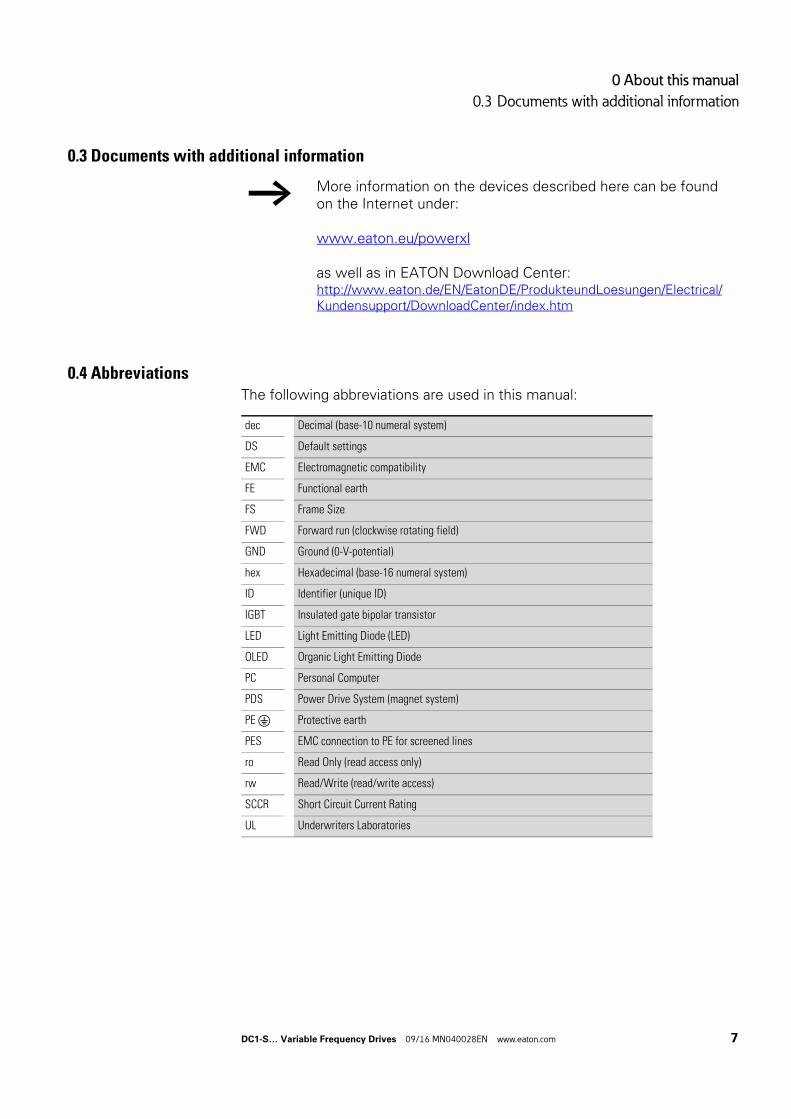
0.3 Documents with additional information
0.4 AbbreviationsThe following abbreviations are used in this manual:
→ More information on the devices described here can be found on the Internet under:
www.eaton.eu/powerxl
as well as in EATON Download Center:http://www.eaton.de/EN/EatonDE/ProdukteundLoesungen/Electrical/Kundensupport/DownloadCenter/index.htm
dec Decimal (base-10 numeral system)
DS Default settings
EMC Electromagnetic compatibility
FE Functional earth
FS Frame Size
FWD Forward run (clockwise rotating field)
GND Ground (0-V-potential)
hex Hexadecimal (base-16 numeral system)
ID Identifier (unique ID)
IGBT Insulated gate bipolar transistor
LED Light Emitting Diode (LED)
OLED Organic Light Emitting Diode
PC Personal Computer
PDS Power Drive System (magnet system)
PE Protective earth
PES EMC connection to PE for screened lines
ro Read Only (read access only)
rw Read/Write (read/write access)
SCCR Short Circuit Current Rating
UL Underwriters Laboratories
DC1-S… Variable Frequency Drives 09/16 MN040028EN www.eaton.com 7
0 About this manual
0.5 Mains supply voltages
0.5 Mains supply voltages
The rated operating voltages stated in the following table are based on the standard values for networks with a grounded star point.
In ring networks (as found in Europe) the rated operating voltage at the transfer point of the power supply companies is the same as the value in the consumer networks (e.g. 230 V).
In star networks (as found in North America), the rated operating voltage at the transfer point of the utility companies is higher than in the consumer network.Example: 115 V → 110 V, 240 V → 230 V, 480 V → 460 V.
The DC1-S… variable frequency drive’s wide tolerance range takes into account a permissible voltage drop of 10 % (i.e. ULN - 10 %).
The rated mains voltage operational data is always based on mains frequencies of 50/60 Hz within a range of 48 to 62 Hz.
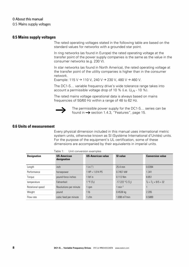
0.6 Units of measurementEvery physical dimension included in this manual uses international metric system units, otherwise known as SI (Système International d’Unités) units. For the purpose of the equipment’s UL certification, some of these dimensions are accompanied by their equivalents in imperial units.
Table 1: Unit conversion examples
→ The permissible power supply for the DC1-S… series can be found in → section 1.4.3, “Features”, page 15.
Designation US-Americandesignation
US-American value SI value Conversion value
Length inch 1 in (’’) 25.4 mm 0.0394
Performance horsepower 1 HP = 1.014 PS 0.7457 kW 1.341
Torque pound-force inches 1 lbf in 0.113 Nm 8.851
temperature Fahrenheit 1 °F (TF) -17.222 °C (TC) TF = TC × 9/5 + 32
Rotational speed Revolutions per minute 1 rpm 1 min-1 1
Weight pound 1 lb 0.4536 kg 2.205
Flow rate cubic feed per minute 1 cfm 1.698 m3/min 0.5889
8 DC1-S… Variable Frequency Drives 09/16 MN040028EN www.eaton.com
1 Device series DC1-S…
1.1 Introduction
1 Device series DC1-S…
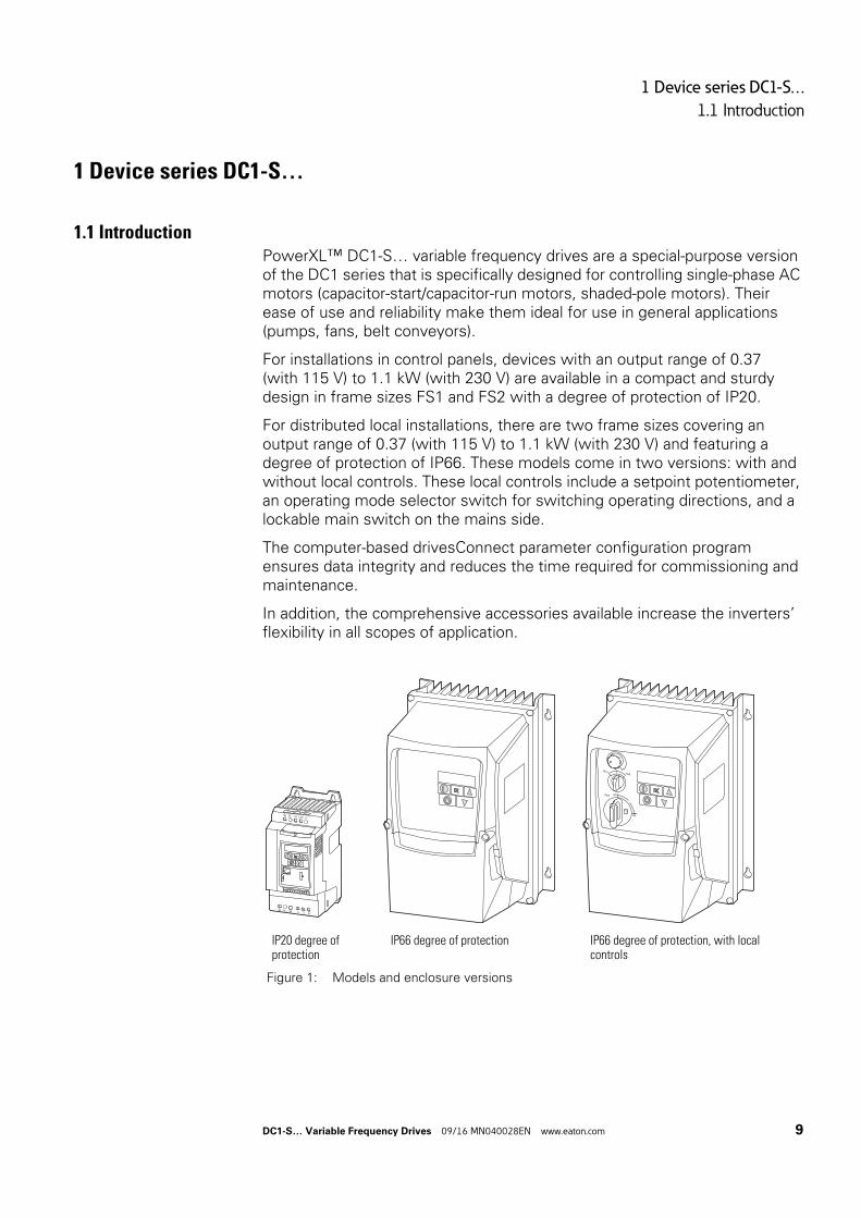
1.1 IntroductionPowerXL™ DC1-S… variable frequency drives are a special-purpose version of the DC1 series that is specifically designed for controlling single-phase AC motors (capacitor-start/capacitor-run motors, shaded-pole motors). Their ease of use and reliability make them ideal for use in general applications (pumps, fans, belt conveyors).
For installations in control panels, devices with an output range of 0.37 (with 115 V) to 1.1 kW (with 230 V) are available in a compact and sturdy design in frame sizes FS1 and FS2 with a degree of protection of IP20.
For distributed local installations, there are two frame sizes covering an output range of 0.37 (with 115 V) to 1.1 kW (with 230 V) and featuring a degree of protection of IP66. These models come in two versions: with and without local controls. These local controls include a setpoint potentiometer, an operating mode selector switch for switching operating directions, and a lockable main switch on the mains side.
The computer-based drivesConnect parameter configuration program ensures data integrity and reduces the time required for commissioning and maintenance.
In addition, the comprehensive accessories available increase the inverters’ flexibility in all scopes of application.
IP20 degree of protection
IP66 degree of protection IP66 degree of protection, with local controls
Figure 1: Models and enclosure versions
L1/L L2/N L3DC-
UDC+ BR
V W
1 2 3 4 5 6 7 8 9 10 11
PWR OFF
ON
REVFWD
0
DC1-S… Variable Frequency Drives 09/16 MN040028EN www.eaton.com 9
1 Device series DC1-S…
1.2 System overview
1.2 System overview
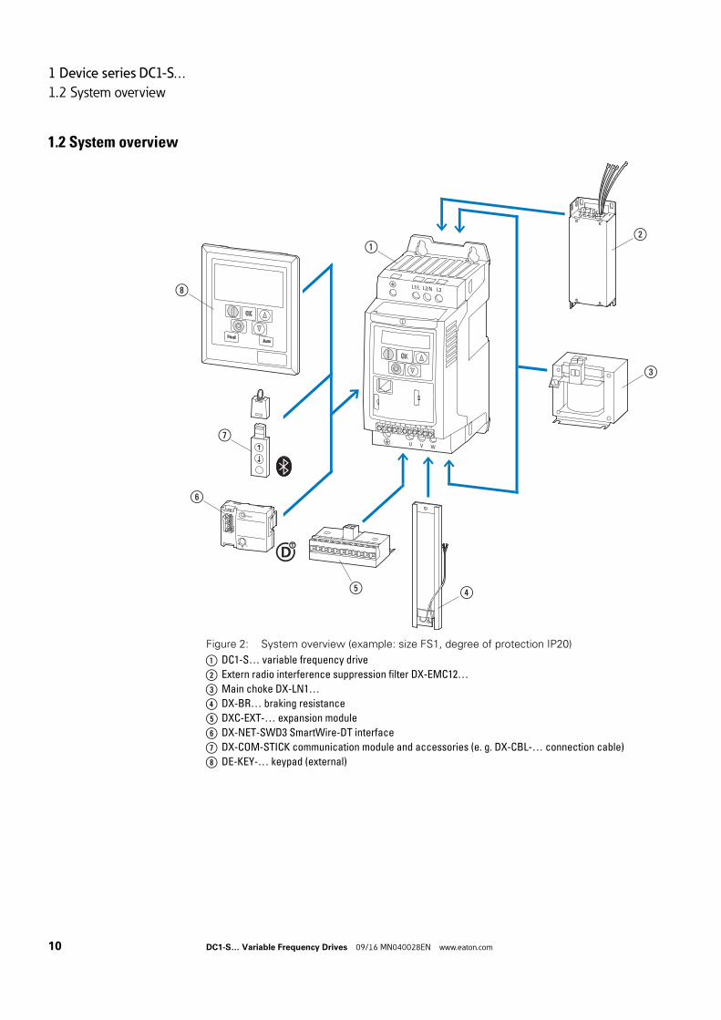
Figure 2: System overview (example: size FS1, degree of protection IP20)
a DC1-S… variable frequency drive
b Extern radio interference suppression filter DX-EMC12…
c Main choke DX-LN1…
d DX-BR… braking resistance
e DXC-EXT-… expansion module
f DX-NET-SWD3 SmartWire-DT interface
g DX-COM-STICK communication module and accessories (e. g. DX-CBL-… connection cable)
h DE-KEY-… keypad (external)
Ready
IO
A
L1/L L2/N L3
U V W
1 2 3 4 5 6 7 8 9 10 11
①
⑥
⑤
⑦
③
②
④
⑧
10 DC1-S… Variable Frequency Drives 09/16 MN040028EN www.eaton.com
1 Device series DC1-S…
1.3 Checking the Delivery
1.3 Checking the Delivery
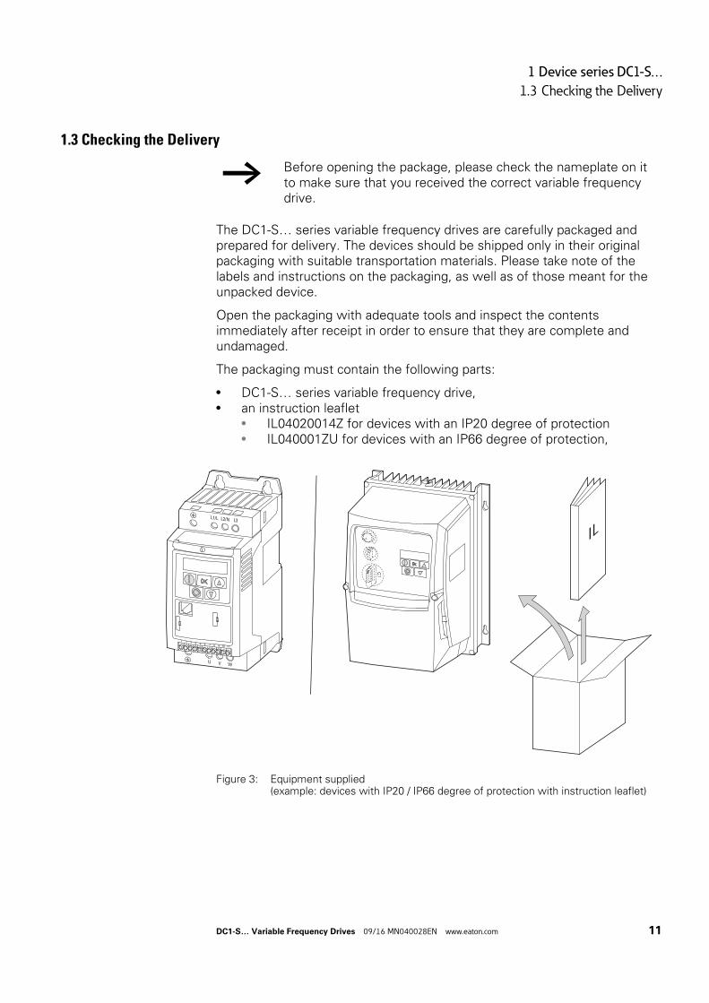
The DC1-S… series variable frequency drives are carefully packaged and prepared for delivery. The devices should be shipped only in their original packaging with suitable transportation materials. Please take note of the labels and instructions on the packaging, as well as of those meant for the unpacked device.
Open the packaging with adequate tools and inspect the contents immediately after receipt in order to ensure that they are complete and undamaged.
The packaging must contain the following parts:
• DC1-S… series variable frequency drive,• an instruction leaflet
• IL04020014Z for devices with an IP20 degree of protection• IL040001ZU for devices with an IP66 degree of protection,
Figure 3: Equipment supplied (example: devices with IP20 / IP66 degree of protection with instruction leaflet)
→ Before opening the package, please check the nameplate on it to make sure that you received the correct variable frequency drive.
L1/L L2/N L3
U V W
1 2 3 4 5 6 7 8 9 10 11
DC1-S… Variable Frequency Drives 09/16 MN040028EN www.eaton.com 11
1 Device series DC1-S…
1.4 Rated operational data
1.4 Rated operational data
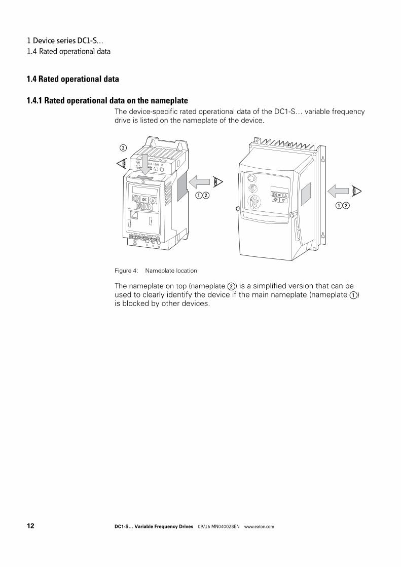
1.4.1 Rated operational data on the nameplateThe device-specific rated operational data of the DC1-S… variable frequency drive is listed on the nameplate of the device.
Figure 4: Nameplate location
The nameplate on top (nameplate ②) is a simplified version that can be used to clearly identify the device if the main nameplate (nameplate ①) is blocked by other devices.
L1/L L2/N L3
U V W
1 2 3 4 5 6 7 8 9 10 11
②
①②
①②
12 DC1-S… Variable Frequency Drives 09/16 MN040028EN www.eaton.com
1 Device series DC1-S…
1.4 Rated operational data
Nameplate inscription
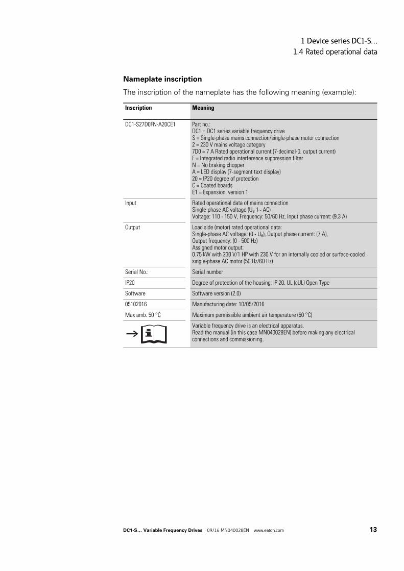
The inscription of the nameplate has the following meaning (example):
Inscription Meaning
DC1-S27D0FN-A20CE1 Part no.:DC1 = DC1 series variable frequency driveS = Single-phase mains connection/single-phase motor connection2 = 230 V mains voltage category7D0 = 7 A Rated operational current (7-decimal-0, output current)F = Integrated radio interference suppression filterN = No braking chopperA = LED display (7-segment text display)20 = IP20 degree of protectionC = Coated boardsE1 = Expansion, version 1
Input Rated operational data of mains connectionSingle-phase AC voltage (Ue 1~ AC)Voltage: 110 - 150 V, Frequency: 50/60 Hz, Input phase current: (9.3 A)
Output Load side (motor) rated operational data:Single-phase AC voltage: (0 - Ue), Output phase current: (7 A),Output frequency: (0 - 500 Hz)Assigned motor output:0.75 kW with 230 V/1 HP with 230 V for an internally cooled or surface-cooled single-phase AC motor (50 Hz/60 Hz)
Serial No.: Serial number
IP20 Degree of protection of the housing: IP 20, UL (cUL) Open Type
Software Software version (2.0)
05102016 Manufacturing date: 10/05/2016
Max amb. 50 °C Maximum permissible ambient air temperature (50 °C)
Variable frequency drive is an electrical apparatus.Read the manual (in this case MN040028EN) before making any electrical connections and commissioning.
a
DC1-S… Variable Frequency Drives 09/16 MN040028EN www.eaton.com 13
1 Device series DC1-S…
1.4 Rated operational data
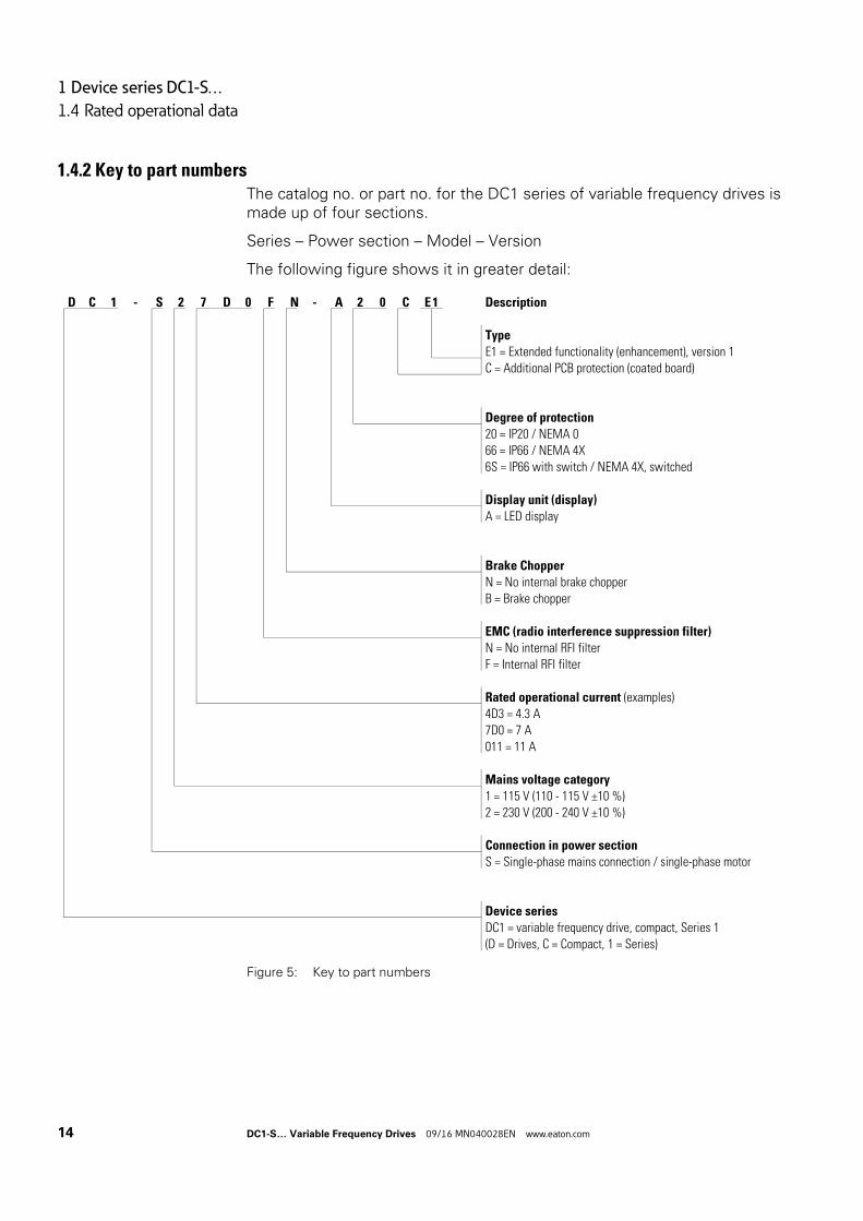
1.4.2 Key to part numbersThe catalog no. or part no. for the DC1 series of variable frequency drives is made up of four sections.
Series – Power section – Model – Version
The following figure shows it in greater detail:
Figure 5: Key to part numbers
D C 1 - S 2 7 D 0 F N - A 2 0 C E 1 Description
Type
E1 = Extended functionality (enhancement), version 1
C = Additional PCB protection (coated board)
Degree of protection
20 = IP20 / NEMA 0
66 = IP66 / NEMA 4X
6S = IP66 with switch / NEMA 4X, switched
Display unit (display)
A = LED display
Brake Chopper
N = No internal brake chopper
B = Brake chopper
EMC (radio interference suppression filter)
N = No internal RFI filter
F = Internal RFI filter
Rated operational current (examples)
4D3 = 4.3 A
7D0 = 7 A
011 = 11 A
Mains voltage category
1 = 115 V (110 - 115 V ±10 %)
2 = 230 V (200 - 240 V ±10 %)
Connection in power section
S = Single-phase mains connection / single-phase motor
Device series
DC1 = variable frequency drive, compact, Series 1
(D = Drives, C = Compact, 1 = Series)
14 DC1-S… Variable Frequency Drives 09/16 MN040028EN www.eaton.com
1 Device series DC1-S…
1.4 Rated operational data
1.4.3 Features
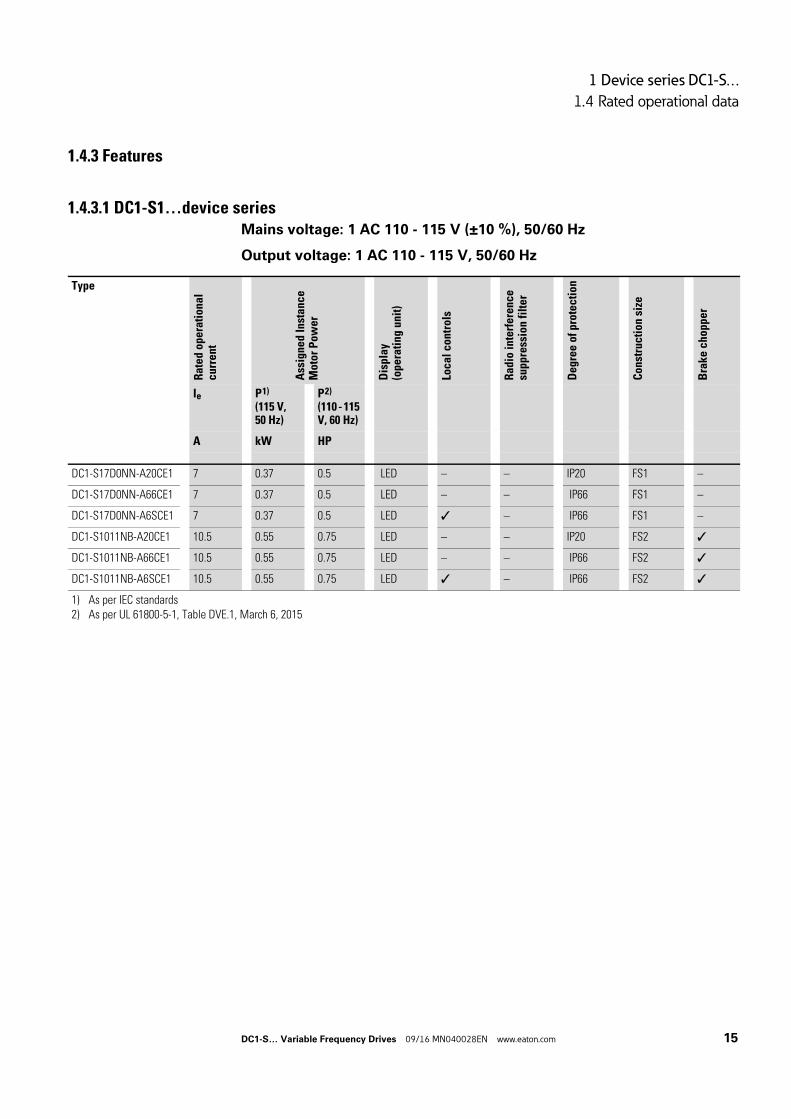
1.4.3.1 DC1-S1…device seriesMains voltage: 1 AC 110 - 115 V (±10 %), 50/60 Hz
Output voltage: 1 AC 110 - 115 V, 50/60 Hz
Type
Rat
ed o
pera
tion
alc
urr
en
t
Ass
igne
d In
stan
ceM
oto
r P
ow
er
Dis
pla
y(o
pera
ting
uni
t)
Loca
l co
ntro
ls
Ra
dio
inte
rfe
ren
cesu
pp
ress
ion
filt
er
De
gre
e o
f pr
ote
cti
on
Con
stru
ctio
n si
ze
Bra
ke
ch
opp
er
Ie P 1)
(115 V, 50 Hz)
P 2)
(110 - 115 V, 60 Hz)
A kW HP
DC1-S17D0NN-A20CE1 7 0.37 0.5 LED – – IP20 FS1 –
DC1-S17D0NN-A66CE1 7 0.37 0.5 LED – – IP66 FS1 –
DC1-S17D0NN-A6SCE1 7 0.37 0.5 LED – IP66 FS1 –
DC1-S1011NB-A20CE1 10.5 0.55 0.75 LED – – IP20 FS2
DC1-S1011NB-A66CE1 10.5 0.55 0.75 LED – – IP66 FS2
DC1-S1011NB-A6SCE1 10.5 0.55 0.75 LED – IP66 FS2
1) As per IEC standards2) As per UL 61800-5-1, Table DVE.1, March 6, 2015
DC1-S… Variable Frequency Drives 09/16 MN040028EN www.eaton.com 15
1 Device series DC1-S…
1.4 Rated operational data
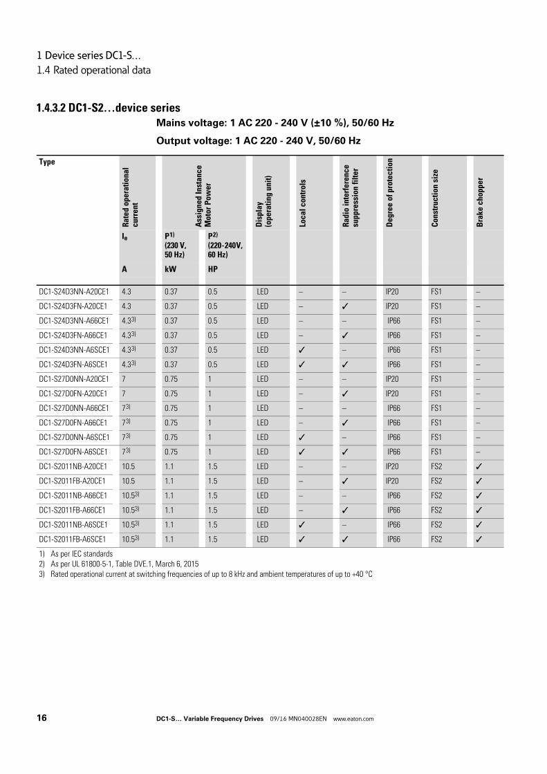
1.4.3.2 DC1-S2…device seriesMains voltage: 1 AC 220 - 240 V (±10 %), 50/60 Hz
Output voltage: 1 AC 220 - 240 V, 50/60 Hz
Type
Rat
ed o
pera
tion
alcu
rre
nt
Ass
igne
d In
stan
ceM
oto
r P
ow
er
Dis
play
(ope
rati
ng u
nit)
Loca
l co
ntro
ls
Ra
dio
inte
rfe
ren
cesu
ppre
ssio
n fi
lter
Deg
ree
of p
rote
ctio
n
Con
stru
ctio
n si
ze
Bra
ke c
hopp
er
Ie P 1)
(230 V, 50 Hz)
P 2)
(220 - 240 V, 60 Hz)
A kW HP
DC1-S24D3NN-A20CE1 4.3 0.37 0.5 LED – – IP20 FS1 –
DC1-S24D3FN-A20CE1 4.3 0.37 0.5 LED – IP20 FS1 –
DC1-S24D3NN-A66CE1 4.3 3) 0.37 0.5 LED – – IP66 FS1 –
DC1-S24D3FN-A66CE1 4.3 3) 0.37 0.5 LED – IP66 FS1 –
DC1-S24D3NN-A6SCE1 4.3 3) 0.37 0.5 LED – IP66 FS1 –
DC1-S24D3FN-A6SCE1 4.3 3) 0.37 0.5 LED IP66 FS1 –
DC1-S27D0NN-A20CE1 7 0.75 1 LED – – IP20 FS1 –
DC1-S27D0FN-A20CE1 7 0.75 1 LED – IP20 FS1 –
DC1-S27D0NN-A66CE1 7 3) 0.75 1 LED – – IP66 FS1 –
DC1-S27D0FN-A66CE1 7 3) 0.75 1 LED – IP66 FS1 –
DC1-S27D0NN-A6SCE1 7 3) 0.75 1 LED – IP66 FS1 –
DC1-S27D0FN-A6SCE1 7 3) 0.75 1 LED IP66 FS1 –
DC1-S2011NB-A20CE1 10.5 1.1 1.5 LED – – IP20 FS2
DC1-S2011FB-A20CE1 10.5 1.1 1.5 LED – IP20 FS2
DC1-S2011NB-A66CE1 10.53) 1.1 1.5 LED – – IP66 FS2
DC1-S2011FB-A66CE1 10.53) 1.1 1.5 LED – IP66 FS2
DC1-S2011NB-A6SCE1 10.53) 1.1 1.5 LED – IP66 FS2
DC1-S2011FB-A6SCE1 10.53) 1.1 1.5 LED IP66 FS2
1) As per IEC standards2) As per UL 61800-5-1, Table DVE.1, March 6, 20153) Rated operational current at switching frequencies of up to 8 kHz and ambient temperatures of up to +40 °C
16 DC1-S… Variable Frequency Drives 09/16 MN040028EN www.eaton.com
1 Device series DC1-S…
1.5 Description
1.5 Description
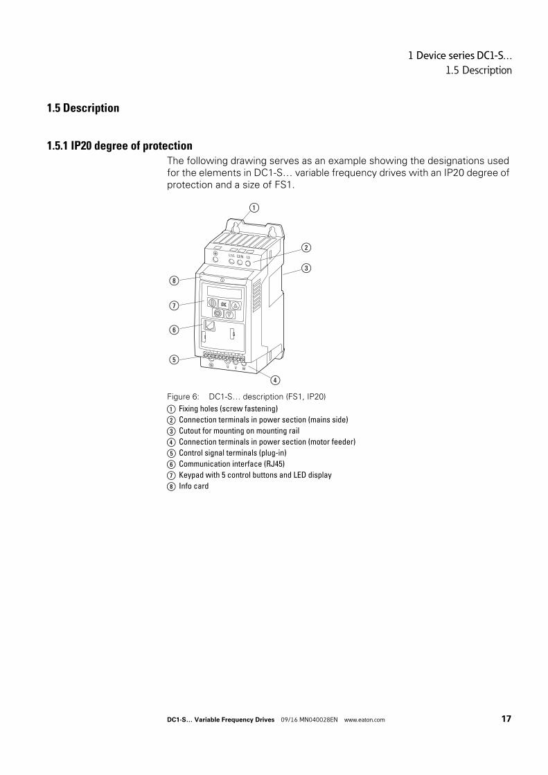
1.5.1 IP20 degree of protectionThe following drawing serves as an example showing the designations used for the elements in DC1-S… variable frequency drives with an IP20 degree of protection and a size of FS1.
Figure 6: DC1-S… description (FS1, IP20)
a Fixing holes (screw fastening)
b Connection terminals in power section (mains side)
c Cutout for mounting on mounting rail
d Connection terminals in power section (motor feeder)
e Control signal terminals (plug-in)
f Communication interface (RJ45)
g Keypad with 5 control buttons and LED display
h Info card
L1/L L2/N L3
U V W
1 2 3 4 5 6 7 8 9 10 11
⑧
⑦
⑥
⑤
①
②
③
④
DC1-S… Variable Frequency Drives 09/16 MN040028EN www.eaton.com 17
1 Device series DC1-S…
1.5 Description
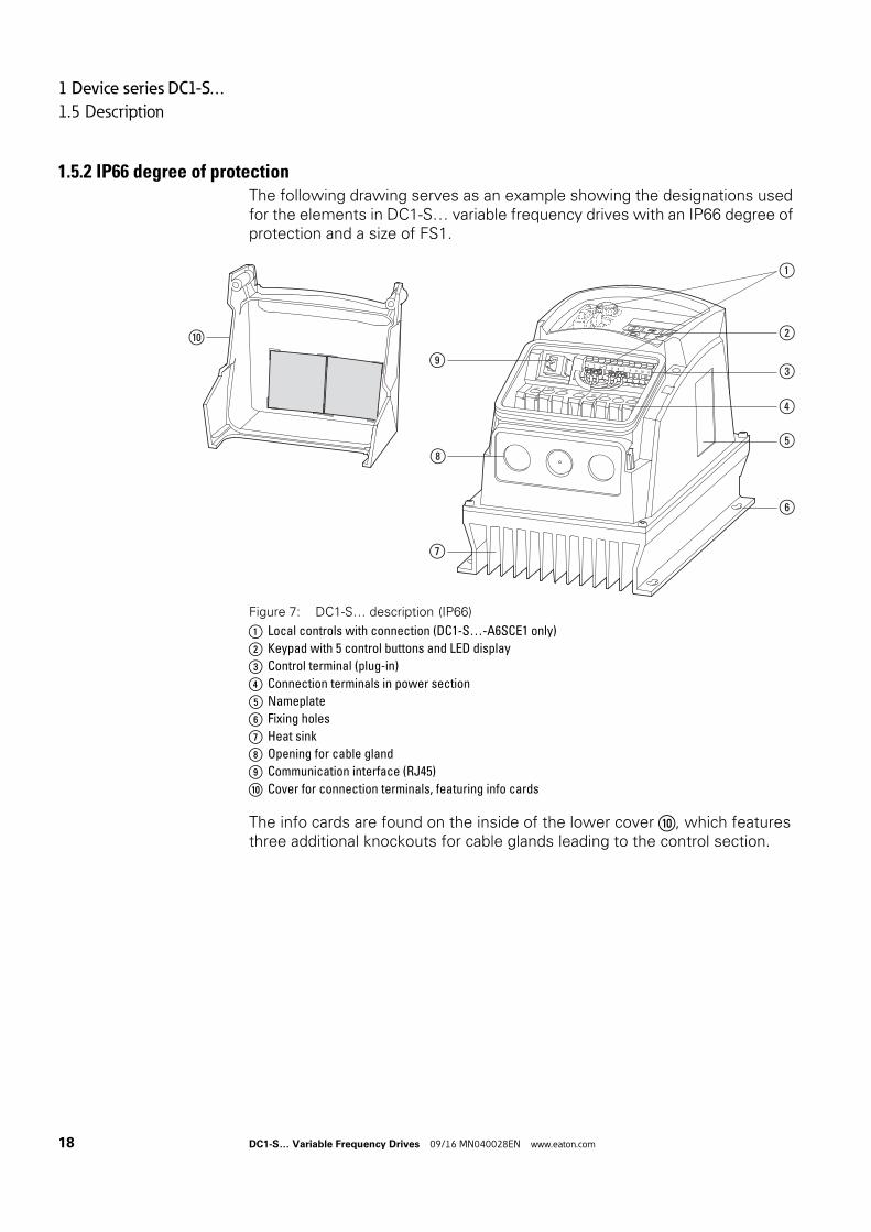
1.5.2 IP66 degree of protectionThe following drawing serves as an example showing the designations used for the elements in DC1-S… variable frequency drives with an IP66 degree of protection and a size of FS1.
Figure 7: DC1-S… description (IP66)
a Local controls with connection (DC1-S…-A6SCE1 only)
b Keypad with 5 control buttons and LED display
c Control terminal (plug-in)
d Connection terminals in power section
e Nameplate
f Fixing holes
g Heat sink
h Opening for cable gland
i Communication interface (RJ45)
j Cover for connection terminals, featuring info cards
The info cards are found on the inside of the lower cover ⑩, which features three additional knockouts for cable glands leading to the control section.
L2NL3
UV W
L1N
1 2 3 4 5 6 7 8 9 10
1 2 3 4 5 6 7 8 9 10 11
①
⑨
⑦
②
③
④
⑤
⑥
⑩
⑧
18 DC1-S… Variable Frequency Drives 09/16 MN040028EN www.eaton.com
1 Device series DC1-S…
1.6 Voltage categories
1.6 Voltage categories
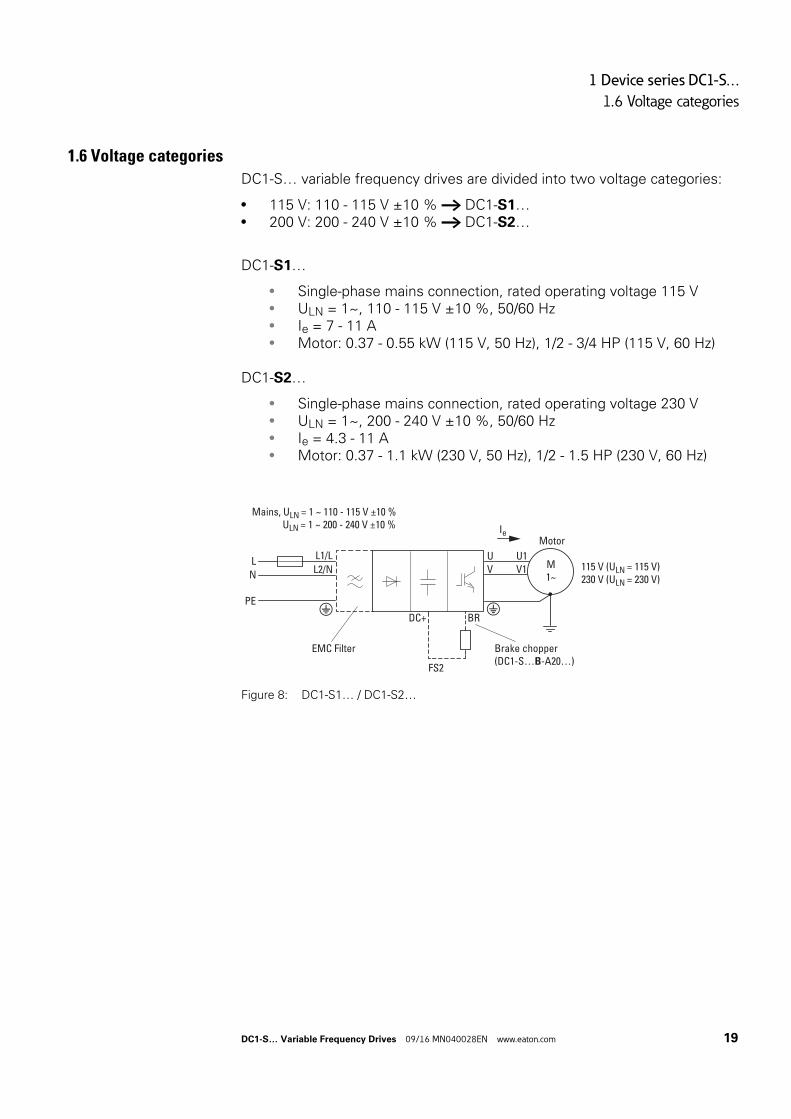
DC1-S… variable frequency drives are divided into two voltage categories:
• 115 V: 110 - 115 V ±10 % → DC1-S1…• 200 V: 200 - 240 V ±10 % → DC1-S2…
DC1-S1…
• Single-phase mains connection, rated operating voltage 115 V• ULN = 1~, 110 - 115 V ±10 %, 50/60 Hz• Ie = 7 - 11 A• Motor: 0.37 - 0.55 kW (115 V, 50 Hz), 1/2 - 3/4 HP (115 V, 60 Hz)
DC1-S2…
• Single-phase mains connection, rated operating voltage 230 V• ULN = 1~, 200 - 240 V ±10 %, 50/60 Hz• Ie = 4.3 - 11 A• Motor: 0.37 - 1.1 kW (230 V, 50 Hz), 1/2 - 1.5 HP (230 V, 60 Hz)
Figure 8: DC1-S1… / DC1-S2…
Mains, ULN = 1 ~ 110 - 115 V ±10 % ULN = 1 ~ 200 - 240 V ±10 %
115 V (ULN = 115 V)230 V (ULN = 230 V)
LN
PE
UV
U1V1
EMC Filter
L1/LL2/N
BRDC+
M1∼
MotorIe
Brake chopper(DC1-S…B-A20…)
FS2
DC1-S… Variable Frequency Drives 09/16 MN040028EN www.eaton.com 19
1 Device series DC1-S…
1.7 Selection Criteria
1.7 Selection Criteria
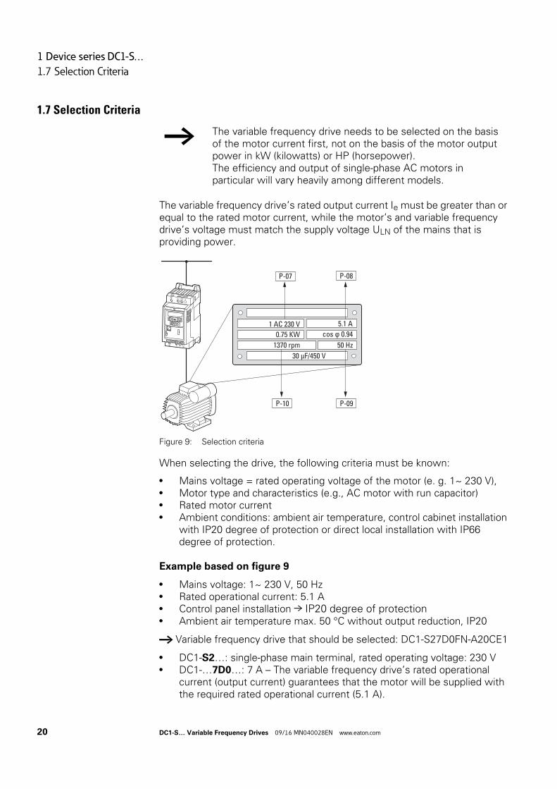
The variable frequency drive’s rated output current Ie must be greater than or equal to the rated motor current, while the motor’s and variable frequency drive’s voltage must match the supply voltage ULN of the mains that is providing power.
Figure 9: Selection criteria
When selecting the drive, the following criteria must be known:
• Mains voltage = rated operating voltage of the motor (e. g. 1~ 230 V),• Motor type and characteristics (e.g., AC motor with run capacitor)• Rated motor current• Ambient conditions: ambient air temperature, control cabinet installation
with IP20 degree of protection or direct local installation with IP66 degree of protection.
Example based on figure 9
• Mains voltage: 1~ 230 V, 50 Hz• Rated operational current: 5.1 A• Control panel installation → IP20 degree of protection• Ambient air temperature max. 50 °C without output reduction, IP20
→ Variable frequency drive that should be selected: DC1-S27D0FN-A20CE1
• DC1-S2…: single-phase main terminal, rated operating voltage: 230 V• DC1-…7D0…: 7 A – The variable frequency drive’s rated operational
current (output current) guarantees that the motor will be supplied with the required rated operational current (5.1 A).
→ The variable frequency drive needs to be selected on the basis of the motor current first, not on the basis of the motor output power in kW (kilowatts) or HP (horsepower).The efficiency and output of single-phase AC motors in particular will vary heavily among different models.
1370 rpm
1 AC 230 V 5.1 A
50 Hz
0.75 KW cos ϕ 0.94
P-07 P-08
P-10 P-09
L1/L L2/N L3
U V W
1 2 3 4 5 6 7 8 9 10 11
30 μF/450 V
20 DC1-S… Variable Frequency Drives 09/16 MN040028EN www.eaton.com
1 Device series DC1-S…
1.8 Output reduction (derating)
1.8 Output reduction (derating)
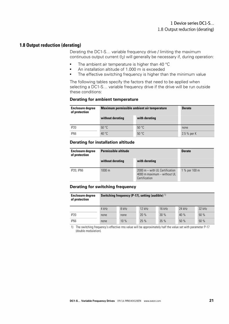
Derating the DC1-S… variable frequency drive / limiting the maximum continuous output current (I2) will generally be necessary if, during operation:
• The ambient air temperature is higher than 40 °C• An installation altitude of 1.000 m is exceeded• The effective switching frequency is higher than the minimum value
The following tables specify the factors that need to be applied when selecting a DC1-S… variable frequency drive if the drive will be run outside these conditions:
Derating for ambient temperature
Derating for installation altitude
Derating for switching frequency
Enclosure degree of protection
Maximum permissible ambient air temperature Derate
without derating with derating
IP20 50 °C 50 °C none
IP66 40 °C 50 °C 2.5 % per K
Enclosure degree of protection
Permissible altitude Derate
without derating with derating
IP20, IP66 1000 m 2000 m – with UL Certification4000 m maximum – without UL Certification
1 % per 100 m
Enclosure degree of protection
Switching frequency (P-17), setting (audible) 1)
4 kHz 8 kHz 12 kHz 16 kHz 24 kHz 32 kHz
IP20 none none 20 % 30 % 40 % 50 %
IP66 none 10 % 25 % 35 % 50 % 50 %
1) The switching frequency’s effective rms value will be approximately half the value set with parameter P-17 (double modulation).
DC1-S… Variable Frequency Drives 09/16 MN040028EN www.eaton.com 21
1 Device series DC1-S…
1.8 Output reduction (derating)
Examples showing how to apply derating factors
0.75 kW motor (230 V, 5.1 A), installation altitude of 2,000 m above sea level, ambient temperature of 45 °C, wall-mounted in mechanical room, required carrier frequency of 16 kHz (reduced operating noise).
a)Selected variable frequency drive: DC1-S27D0FN-A6SCE1, rated operational current of 7 A, carrier frequency of 8 kHz (default setting).
Required derating factors:
• For the 16 kHz switching frequency: 35 %• For the 2,000 m installation altitude: 10 % (1 % per 100 m above
1,000 m, 2,000 m - 1,000 m = 1,000 m, 1,000 m/100 m = 10)• For the 45 °C ambient temperature: 12.5 % (2.5 % per kelvin,
45 °C - 40 °C = 5 K, IP66 degree of protection)
7 A - 35 % - 10 % - 12.5 % = (7 x 0.65 x 0.9 x 0.875) A = 3.58 A
The DC1-S variable frequency drive’s permissible continuous rated operational current of 3.58 A is lower than the motor’s required rated operational current (5 A).
b)Selected variable frequency drive: DC1-S2011FB-A6SCE1, rated operational current of 11 A.
Required derating factors:
• For the 16 kHz switching frequency: 35 %• For the 2,000 m installation altitude: 10 % (1 % per 100 m above
1,000 m, 2,000 m - 1,000 m = 1,000 m, 1,000 m/100 m = 10)• For the 45 °C ambient temperature: 12.5 %
(2.5 % per kelvin, 45 °C - 40 °C = 5 K, IP66 degree of protection).
11 A - 35 % - 10 % - 12.5 % = (14 x 0.65 x 0.9 x 0.875) A = approx. 5.63 A
→ The DC1-S2011FB-A6SCE1 variable frequency drive meets the necessary operating conditions.
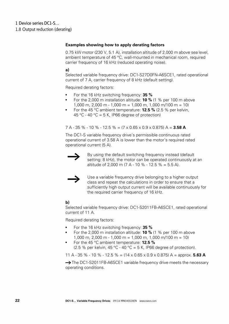
→ By using the default switching frequency instead (default setting: 8 kHz), the motor can be operated continuously at an altitude of 2,000 m (7 A - 10 % - 12.5 % = 5.5 A).
→ Use a variable frequency drive belonging to a higher output class and repeat the calculations in order to ensure that a sufficiently high output current will be available continuously for the required carrier frequency of 16 kHz.
22 DC1-S… Variable Frequency Drives 09/16 MN040028EN www.eaton.com
1 Device series DC1-S…
1.9 Proper use
1.9 Proper use
DC1-S… variable frequency drives are electrical devices for controlling variable speed drives with single-phase AC motors. They are designed for installation in machines or for use in combination with other components within a machine or system.
The DC1-S… variable frequency drives are not domestic appliances. They are designed only for industrial use as system components.
If the variable frequency drive is installed in a machine, it is prohibited to place it into operation until it has been determined that the corresponding machine meets the safety and protection requirements set forth in Machinery Safety Directive 2006/42/EC (e.g., by complying with EN 60204). The user of the equipment is responsible for ensuring that the machine use complies with the relevant EU Directives.
The CE marking on DC1-S… variable frequency drives confirms that the devices meet the requirements set forth in the European Union’s Low Voltage and EMC Directives (Directives 2014/35/EU, 2014/30/EU, and ROHS 2011/65/EU) when used in their typical drive configuration.
In the described system configurations, DC1-S… variable frequency drives are suitable for use in public and non-public networks.
Connecting a DC1-S… variable frequency drive with an integrated radio interference suppression filter to an IT grounding system (network without a direct connection to ground) is only permissible under certain conditions, as the device’s internal filter capacitors will connect the network to ground potential (enclosure). In ungrounded networks, this can result in hazardous situations or damage to the device (insulation monitoring is required!).
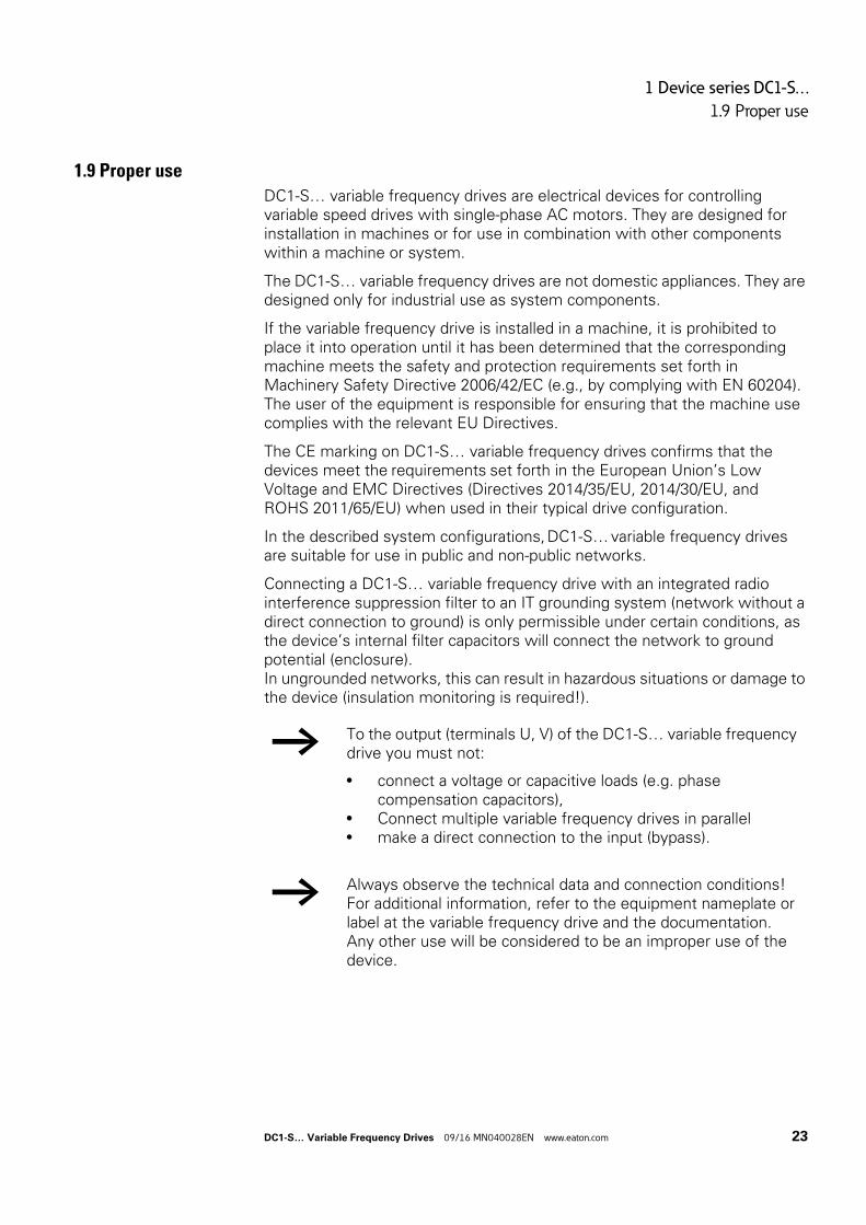
→ To the output (terminals U, V) of the DC1-S… variable frequency drive you must not:
• connect a voltage or capacitive loads (e.g. phase compensation capacitors),
• Connect multiple variable frequency drives in parallel• make a direct connection to the input (bypass).
→ Always observe the technical data and connection conditions!For additional information, refer to the equipment nameplate or label at the variable frequency drive and the documentation.Any other use will be considered to be an improper use of the device.
DC1-S… Variable Frequency Drives 09/16 MN040028EN www.eaton.com 23
1 Device series DC1-S…
1.10 Maintenance and inspection
1.10 Maintenance and inspection
DC1-S… series variable frequency drives will be maintenance-free as long as the general rated operational data (see annex) is adhered to and the specific technical data (see annex) for the corresponding ratings is taken into account. Please note, however, that external influences may affect the operation and lifespan of a DC1-S… variable frequency drive.
We therefore recommend that the devices are checked regularly and the following maintenance measures are carried out at the specified intervals.
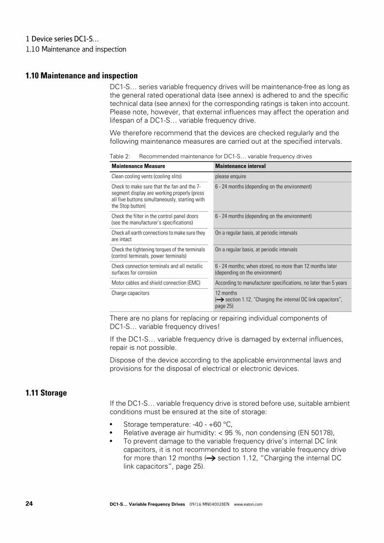
Table 2: Recommended maintenance for DC1-S… variable frequency drives
There are no plans for replacing or repairing individual components of DC1-S… variable frequency drives!
If the DC1-S… variable frequency drive is damaged by external influences, repair is not possible.
Dispose of the device according to the applicable environmental laws and provisions for the disposal of electrical or electronic devices.
1.11 StorageIf the DC1-S… variable frequency drive is stored before use, suitable ambient conditions must be ensured at the site of storage:
• Storage temperature: -40 - +60 °C,• Relative average air humidity: < 95 %, non condensing (EN 50178),• To prevent damage to the variable frequency drive’s internal DC link
capacitors, it is not recommended to store the variable frequency drive for more than 12 months (→ section 1.12, “Charging the internal DC link capacitors”, page 25).
Maintenance Measure Maintenance interval
Clean cooling vents (cooling slits) please enquire
Check to make sure that the fan and the 7-segment display are working properly (press all five buttons simultaneously, starting with the Stop button)
6 - 24 months (depending on the environment)
Check the filter in the control panel doors(see the manufacturer’s specifications)
6 - 24 months (depending on the environment)
Check all earth connections to make sure they are intact
On a regular basis, at periodic intervals
Check the tightening torques of the terminals (control terminals, power terminals)
On a regular basis, at periodic intervals
Check connection terminals and all metallic surfaces for corrosion
6 - 24 months; when stored, no more than 12 months later (depending on the environment)
Motor cables and shield connection (EMC) According to manufacturer specifications, no later than 5 years
Charge capacitors 12 months(→ section 1.12, “Charging the internal DC link capacitors”, page 25)
24 DC1-S… Variable Frequency Drives 09/16 MN040028EN www.eaton.com
1 Device series DC1-S…
1.12 Charging the internal DC link capacitors
1.12 Charging the internal DC link capacitors
After extended storage times or extended downtimes during which no power is supplied (> 12 months), the capacitors in the internal DC link must be recharged in a controlled manner in order to prevent damage. To do this, the DC1-S… variable frequency drive must be supplied with power, with a controlled DC power supply unit, via the mains connection terminals (e.g., L1/L und L2/N).
In order to prevent the capacitors from having excessively high leakage currents, the inrush current should be limited to approximately 300 to 800 mA (depending on the relevant rating). The variable frequency drive must not be enabled during this time (i.e. no start signal). After this, the DC voltage must be set to the magnitudes for the corresponding DC link voltage (UDC ∼ 1.41 x Ue) and applied for one hour at least (regeneration time).
• DC1-S1…: about 162 V DC at Ue = 115 V AC• DC1-S2…: about 324 V DC at Ue = 230 V AC
1.13 Service and warrantyIn the unlikely event that you have a problem with your DC1-S… variable frequency drive, please contact your local sales office.
When you call, have the following data ready:
• The exact variable frequency drive part number (see nameplate),• the date of purchase• a detailed description of the problem which has occurred with the
variable frequency drive.
If some of the information printed on the rating plate is not legible, please state only the data which are clearly legible.
Information concerning the guarantee can be found in the Terms and Conditions Eaton Industries GmbH.
Break-Down Service
Please contact your local office:
http://www.eaton.eu/aftersales
or
Hotline After Sales Service
+49 (0) 180 5 223822 (de, en)
DC1-S… Variable Frequency Drives 09/16 MN040028EN www.eaton.com 25

1 Device series DC1-S…
1.13 Service and warranty
26 DC1-S… Variable Frequency Drives 09/16 MN040028EN www.eaton.com
2 Engineering
2.1 Introduction
2 Engineering
2.1 IntroductionThis chapter describes the most important features in the energy circuit of a magnet system (PDS = Power Drive System), which you should take into consideration in your project planning.It contains instructions that must be followed when determining which device to use with which rated motor output, as well as when selecting protection devices and switchgear, selecting cables, cable entries, and operating the DC1-S… variable frequency drive.All applicable laws and local standards must be complied with when planning and carrying out the installation. Not following the recommendations provided may result in problems what will not be covered by the warranty.
DC1-S… Variable Frequency Drives 09/16 MN040028EN www.eaton.com 27
2 Engineering
2.1 Introduction
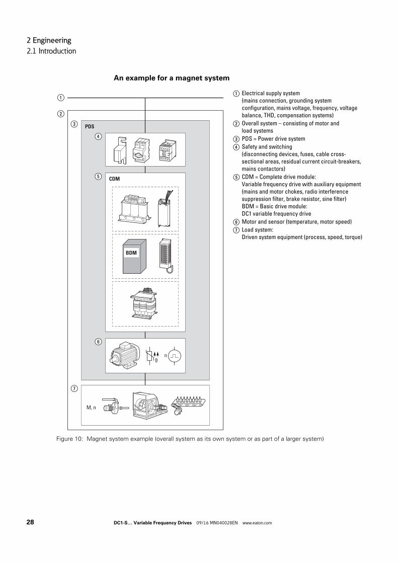
An example for a magnet system
a Electrical supply system(mains connection, grounding system configuration, mains voltage, frequency, voltage balance, THD, compensation systems)
b Overall system – consisting of motor and load systems
c PDS = Power drive system
d Safety and switching(disconnecting devices, fuses, cable cross-sectional areas, residual current circuit-breakers, mains contactors)
e CDM = Complete drive module:Variable frequency drive with auxiliary equipment (mains and motor chokes, radio interference suppression filter, brake resistor, sine filter)BDM = Basic drive module:DC1 variable frequency drive
f Motor and sensor (temperature, motor speed)
g Load system:Driven system equipment (process, speed, torque)
Figure 10: Magnet system example (overall system as its own system or as part of a larger system)
ϑn
BDM
M, n
PDS
CDM
⑥
⑦
⑤
④
③
②
①
28 DC1-S… Variable Frequency Drives 09/16 MN040028EN www.eaton.com
2 Engineering
2.2 Electrical power network
2.2 Electrical power network
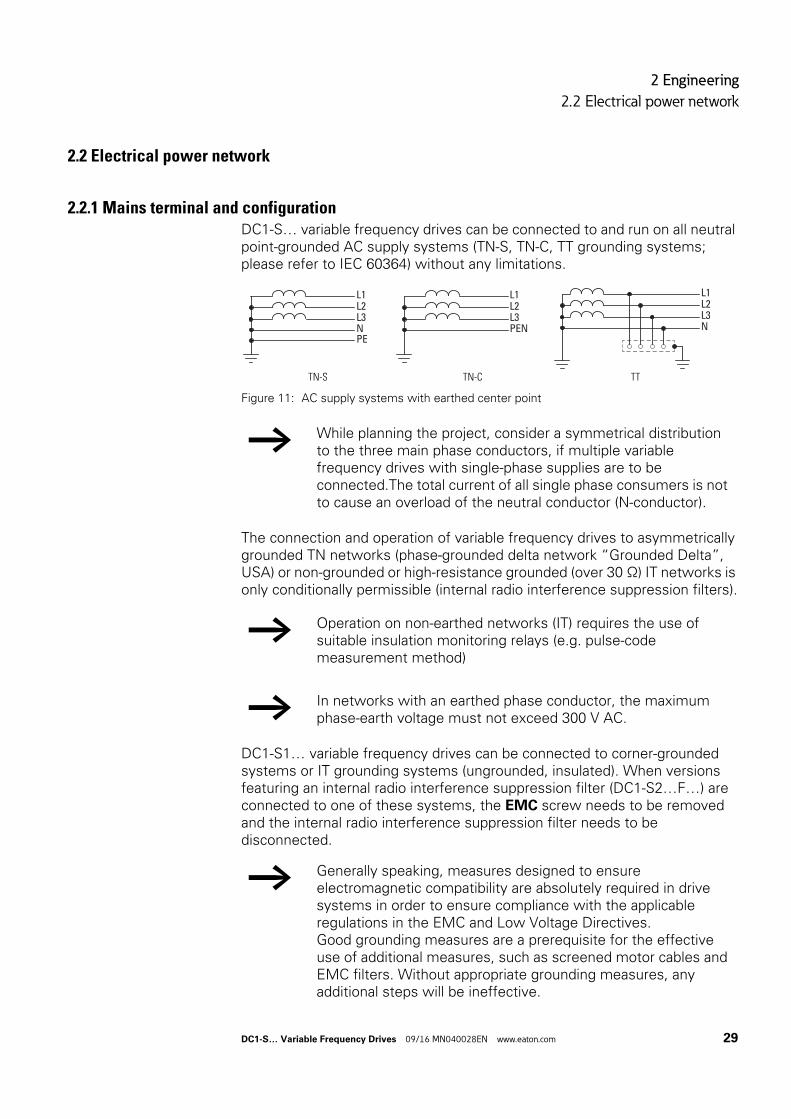
2.2.1 Mains terminal and configurationDC1-S… variable frequency drives can be connected to and run on all neutral point-grounded AC supply systems (TN-S, TN-C, TT grounding systems; please refer to IEC 60364) without any limitations.
Figure 11: AC supply systems with earthed center point
The connection and operation of variable frequency drives to asymmetrically grounded TN networks (phase-grounded delta network “Grounded Delta”, USA) or non-grounded or high-resistance grounded (over 30 Ω) IT networks is only conditionally permissible (internal radio interference suppression filters).
DC1-S1… variable frequency drives can be connected to corner-grounded systems or IT grounding systems (ungrounded, insulated). When versions featuring an internal radio interference suppression filter (DC1-S2…F…) are connected to one of these systems, the EMC screw needs to be removed and the internal radio interference suppression filter needs to be disconnected.
TN-S TN-C TT
→ While planning the project, consider a symmetrical distribution to the three main phase conductors, if multiple variable frequency drives with single-phase supplies are to be connected.The total current of all single phase consumers is not to cause an overload of the neutral conductor (N-conductor).
→ Operation on non-earthed networks (IT) requires the use of suitable insulation monitoring relays (e.g. pulse-code measurement method)
→ In networks with an earthed phase conductor, the maximum phase-earth voltage must not exceed 300 V AC.
→ Generally speaking, measures designed to ensure electromagnetic compatibility are absolutely required in drive systems in order to ensure compliance with the applicable regulations in the EMC and Low Voltage Directives.Good grounding measures are a prerequisite for the effective use of additional measures, such as screened motor cables and EMC filters. Without appropriate grounding measures, any additional steps will be ineffective.
L2
N
L1
L3
PE
L2
PEN
L1
L3L2
N
L1
L3
DC1-S… Variable Frequency Drives 09/16 MN040028EN www.eaton.com 29
2 Engineering
2.3 Cable cross-sections
2.2.2 Mains voltage and frequencyThe standardized rated operating voltages (IEC 60038, VDE 017-1) of power utilities guarantee the following conditions at the connection point:
• Deviation from the rated value of voltage: maximum ±10 %• Deviation in voltage phase balance: maximum ±3 %• Deviation from rated value of the frequency: maximum ±4 %
The broad tolerance band of the DC1-S… variable frequency drive considers the rated value forEuropean as (EU: ULN = 230 V, 50 Hz) andAmerican as (USA: ULN = 115 V/240 , 60 Hz) standard voltages:
• 115 V, 50 Hz (EU) and 115 V, 60 Hz (USA) at DC1-S1…,110 V -10 % - 115 V +10 % (99 V -0 % - 126 V +0 %)
• 230 V, 50 Hz (EU) and 240 V, 60 Hz (USA) at DC1-S2…200 V -10 % - 240 V +10 % (180 V -0 % - 264 V +0 %)
The permissible frequency range for all voltage categories is 50/60 Hz (48 Hz - 0 % - 62 Hz + 0 %).
2.2.3 Reactive power compensation devicesCompensation on the power supply side is not required for the variable frequency drives of the DC1-S… series. From the AC power supply network they only take on very little reactive power of the fundamental harmonics (cos ϕ ~ 0.98).
2.3 Cable cross-sectionsThe mains cables and motor cables must be sized as required by local standards and by the load currents that will be involved.
The PE conductor’s cross-sectional area must be the same as the phase conductors’ cross-sectional area. The connection terminals marked with must be connected to the earth-current circuit.
→ In the AC supply systems with non-choked reactive current compensation devices, current deviations can enable parallel resonance and undefinable circumstances.
In the project planning for the connection of variable frequency drives to AC supply systems with undefined circumstances, consider using mains chokes.
NOTICE
The specified minimum PE conductor cross-sections (EN 61800-5-1) must be maintained.
30 DC1-S… Variable Frequency Drives 09/16 MN040028EN www.eaton.com
2 Engineering
2.4 Safety and switching
If there are leakage currents greater than 3.5 mA, a reinforced earthing (PE) must be connected, as required by standard EN 61800-5-1. The cable cross-section must be at least 10 mm2, or the earthing system must consist of two separately connected earthing cables.
A symmetrical, fully screened (360°), low-impedance motor cable must be used. The length of the motor cable depends on the RFI class and the environment.
For US installations, UL-listed cables (AWG) should be used exclusively. These cables must have a temperature rating of 70 °C (158 °F), and will often require installation inside a metal conduit (please consult the applicable local standards).
2.4 Safety and switching
2.4.1 Disconnecting device
In the European Union, this disconnecting device must be one of the following devices in order to comply with European Directives as per standard EN 60204-1, "Safety of machinery":
• An AC-23B utilization category disconnector (EN 60947-3)• A disconnector with an auxiliary contact that in all cases will disconnect
the load circuit before the disconnector’s main contacts open (EN 60947-3)
• A circuit-breaker designed to disconnect the circuit as per EN 60947-2
In all other regions, the applicable national and local safety regulations must be complied with.
→ → section 7.2, “Specific rated operational data”, page 161 provides the leakage currents for the individual models.
→ → section 3.5, “EMC installation”, page 55 goes over the EMC requirements for the motor cables.
→ For the rated cable cross-sectional areas for DC1-S… variable frequency drives, please refer to → section 4.1, “Cable cross-sections”, page 89.
→ Install a manual disconnecting device between the mains connection and the DC1-S… variable frequency drive. This disconnecting device must be designed in such a way that it can be interlocked in its open position for installation and maintenance work.
DC1-S… Variable Frequency Drives 09/16 MN040028EN www.eaton.com 31
2 Engineering
2.4 Safety and switching
2.4.2 FusesThe DC1-S… variable frequency drive and the corresponding supply cables must be protected from thermal overload and short-circuits.
The fuses will protect the supply cable in the event of a short-circuit, limit any damage to the variable frequency drive, and prevent damage to upstream devices in the event of a short-circuit in the variable frequency drive.
2.4.3 Residual current circuit-breaker (RCD)DC1-S1… and DC1-S2…variable frequency drives work with a single-phase power supply (L, N), meaning that you can use type A and type B residual current devices (RCD).
The leakage currents’ magnitude will generally depend on:
• length of the motor cable• shielding of the motor cable• height of the switching frequency (switching frequency of the inverter),• design of the radio interference suppression filter• grounding measures at the site of the motor.
Other protective measures against direct and indirect contact can be used for DC1-S… variable frequency drives, including isolating them from the supply system with the use of a transformer.
→ The fuse ratings and cable cross-sectional areas (wire gauges) for the connection on the mains side will depend on the DC1-S… variable frequency drive’s input current ILN.
→ For the recommended fuse sizing and assignments, please refer to → section 4.2, “Fuses”, page 90.
NOTICE
Residual current circuit-breakers (RCD = residual current device) should only be installed between the power feed system (the AC supply system supplying power) and the DC1-S… variable frequency drive – but not at the output to the motor!
32 DC1-S… Variable Frequency Drives 09/16 MN040028EN www.eaton.com
2 Engineering
2.4 Safety and switching
2.4.4 Mains contactorsThe mains contactor enables an operational switching on and off of the supply voltage for the variable frequency drive and switching off in case of a fault. The mains contactor is designed based on the mains-side input current ILN of the DC1-S… variable frequency drive for utilization category AC-1 (IEC 60947) and the ambient air temperature at the location of use.
→ While planning the project, please make sure that inching operation is not done via the mains contactor of the variable frequency drive on frequency-controlled drives, but through a controller input of the variable frequency drive.
The maximum permissible mains voltage switch-on frequency for the DC1-S… variable frequency drive is once every 30 seconds (normal operation).
→ For UL-compliant installation and during operation, the mains side switching devices must allow for a 1.25 times higher input current.
→ For the rated mains contactors for DC1-S… variable frequency drives, please refer to → section 4.3, “Mains contactors”, page 91.
DC1-S… Variable Frequency Drives 09/16 MN040028EN www.eaton.com 33
2 Engineering
2.5 Mains chokes
2.5 Mains chokes
Towards the variable frequency drive, the main chokes dampen the interference from the supply network. This increases the electric strength of the variable frequency drive and lengthens the lifespan (diodes of the mains power rectifier, internal DC link capacitors).
T
→ For the operation of the DC1-S… variable frequency drive, the application of main chokes is not necessary.
However, we recommend using a mains choke if the electrical supply system’s quality is not known:
• Large voltage peaks (e.g., when switching large loads directly)
• Correction systems (without series inductors)• Power supplied via conductor bar or slip ring systems
(e.g., overhead conveyors)
While planning the project, consider that a mains choke is only assigned to a single variable frequency drive for decoupling.
When using an adapting transformer (assigned to a single variable frequency drive), a main choke is not necessary.
Mains chokes are designed based on the mains-side input current (ILN) of the variable frequency drive.
→ When the variable frequency drive is running at its rated current limit, the mains choke with a uK value of around 4 % will cause the variable frequency drive’s maximum possible output voltage U2 to be reduced to about 96 % of the mains voltage ULN.
→ For the rated mains contactors for DC1-S… variable frequency drives, please refer to → section 4.4, “Mains chokes”, page 92.
34 DC1-S… Variable Frequency Drives 09/16 MN040028EN www.eaton.com
2 Engineering
2.6 Radio interference suppression filter
2.6 Radio interference suppression filter
DC1-S2…F… variable frequency drives feature an internal radio interference suppression filter. When combined with a motor cable that is screened and earthed 360° on both ends, they make it possible to comply with the EMC limits for conducted interference for all categories and environments(IEC/EN 61800-3). This requires installation in accordance with EMC requirements, as well as not exceeding permissible motor cable lengths:
• 1 m for category C1 in the 1st environment,• 5 m for category C2 in the 1st and 2nd environment,• 25 m for category C3 in the 2nd environment.
Longer motor cable lengths can be used if additional external radio interference suppression filters (DX-EMC12…) are used.
→ For the rated radio interference suppression filters for DC1-S… variable frequency drives, please refer to → section 4.5, “Radio interference suppression filter”, page 93.
→ The unscreened cable length between the radio interference suppression filter and the variable frequency drive should not exceed 300 mm (maximum of 500 mm depending on the setup inside the metal-enclosed control panel).
DC1-S… Variable Frequency Drives 09/16 MN040028EN www.eaton.com 35
2 Engineering
2.7 Braking resistances
2.7 Braking resistances
In certain operating states, the motor may run as a generator in certain applications (regenerative braking operation).
Examples include:
• Lowering in hoisting gear and conveyor applications• Controlled speed reduction in the case of large load inertias
(flywheels)• A fast speed reduction in dynamic travel drives
When the motor operates as a generator, its braking energy will be fed into the variable frequency drive’s DC link via the inverter. DC link voltage UDC will be increased as a result. If the voltage value is too high, the DC1-S… variable frequency drive will disable its inverter, after which the motor will coast uncontrolled.If there is a braking chopper and a connected braking resistance RB, the braking energy fed back into the variable frequency drive can be dissipated in order to limit the DC link voltage.
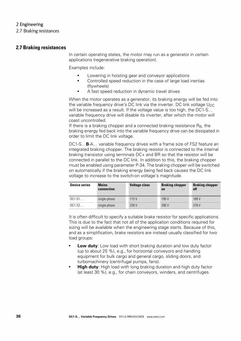
DC1-S…B-A… variable frequency drives with a frame size of FS2 feature an integrated braking chopper. The braking resistor is connected to the internal braking transistor using terminals DC+ and BR so that the resistor will be connected in parallel to the DC link. In addition to this, the braking chopper must be enabled using parameter P-34. The braking chopper will be switched on automatically if the braking energy being fed back causes the DC link voltage to increase to the switch-on voltage’s magnitude.
It is often difficult to specify a suitable brake resistor for specific applications. This is due to the fact that not all of the application conditions required for sizing will be available when the engineering stage starts. Because of this, and as a simplification, brake resistors are instead usually classified for two load groups:
• Low duty: Low load with short braking duration and low duty factor (up to about 25 %), e.g., for horizontal conveyors and handling equipment for bulk cargo and general cargo, sliding doors, and turbomachinery (centrifugal pumps, fans).
• High duty: High load with long braking duration and high duty factor (at least 30 %), e.g., for chain conveyors, winders, and centrifuges.
Device series Mains connection
Voltage class Braking chopper on
Braking chopper off
DC1-S1… single-phase 115 V 195 V 189 V
DC1-S2… single-phase 230 V 390 V 378 V
36 DC1-S… Variable Frequency Drives 09/16 MN040028EN www.eaton.com
2 Engineering
2.7 Braking resistances
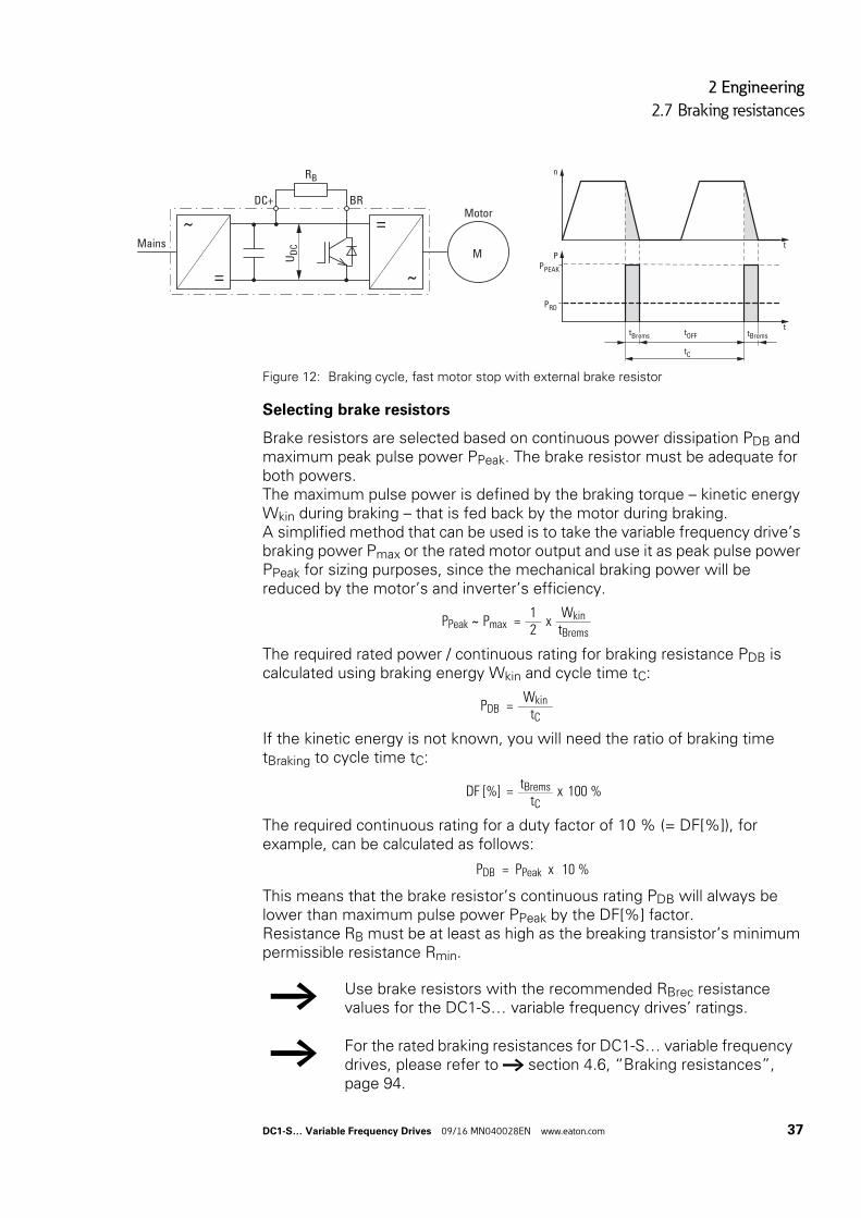
Figure 12: Braking cycle, fast motor stop with external brake resistor
Selecting brake resistors
Brake resistors are selected based on continuous power dissipation PDB and maximum peak pulse power PPeak. The brake resistor must be adequate for both powers.The maximum pulse power is defined by the braking torque – kinetic energy Wkin during braking – that is fed back by the motor during braking. A simplified method that can be used is to take the variable frequency drive’s braking power Pmax or the rated motor output and use it as peak pulse power PPeak for sizing purposes, since the mechanical braking power will be reduced by the motor’s and inverter’s efficiency.
The required rated power / continuous rating for braking resistance PDB is calculated using braking energy Wkin and cycle time tC:
If the kinetic energy is not known, you will need the ratio of braking time tBraking to cycle time tC:
The required continuous rating for a duty factor of 10 % (= DF[%]), for example, can be calculated as follows:
This means that the brake resistor’s continuous rating PDB will always be lower than maximum pulse power PPeak by the DF[%] factor.Resistance RB must be at least as high as the breaking transistor’s minimum permissible resistance Rmin.
M
Motor
Mains
RB
BRDC+
=
~
~
=U
DC
n
tP
PRD
PPEAK
ttBrems tOFF tBrems
tC
PPeak ∼ Pmax =1
xWkin
2 tBrems
PDB =Wkin
tC
DF [%] =tBrems x 100 %
tC
PDB = PPeak x 10 %
→ Use brake resistors with the recommended RBrec resistance values for the DC1-S… variable frequency drives’ ratings.
→ For the rated braking resistances for DC1-S… variable frequency drives, please refer to → section 4.6, “Braking resistances”, page 94.
DC1-S… Variable Frequency Drives 09/16 MN040028EN www.eaton.com 37
2 Engineering
2.8 Switching to the output side
2.8 Switching to the output side
Typical applications for switching at the DC1-S… variable frequency drive’s output include:
• Cases in which a bypass circuit is implemented.• Cases in which the motor must be de-energized quickly in the event of
an emergency switching off (safety shutdown).
When the motor is switched off, the inverter needs to be disabled first (the START enable signal must be switched off) before the contacts (contactor, switch-disconnector) on the variable frequency drive’s output side are opened.
2.8.1 ContactorsThe contactors on the output side of DC1-S… variable frequency drives need to be sized based on utilization category AC-3 (IEC/EN 60947-4-1) for the assigned rated motor current and the corresponding rated operating voltage.
When a motor is being switched off, the DC1-S… variable frequency drive’s output (inverter) must be disabled (the START enable signal must be switched off) before the contacts are opened.
2.8.2 switch-disconnectorsSwitch-disconnectors are used as repair and maintenance switches in industrial, trade, and building service management applications. At the output of variable frequency drives, they are primarily used to locally switch off motors (pumps, fans) that pose a risk of unintended starting during maintenance or repairs. In order to provide greater safety, these switch-disconnectors can be locked out with the use of padlocks, meaning they have characteristics comparable to those of main switches as defined in EN 60204.
Eaton T0…/MSB/…, P1…/MSB/…, and P3…/MSB/… enclosed switch-disconnectors are designed for local installation with an IP65 degree of protection. The internal screening plate ensures that screened motor cables can be easily connected in a way that meets EMC requirements.
The switch-disconnectors on the output side of DC1-S… variable frequency drives need to be sized based on utilization category AC-23A (IEC/EN 60947-3) for the assigned rated motor current and the corresponding rated operating voltage.When a motor is being switched off, the DC1-S… variable frequency drive’s output (inverter) must be disabled (the START enable signal must be switched off) before the contacts are opened.
For more information and technical data on T0…/MSB/…, P1…/MSB/…, and P3…/MSB/… switch-disconnectors, please refer to instruction leaflets IL008020ZU as well as IL008037ZU.
a
38 DC1-S… Variable Frequency Drives 09/16 MN040028EN www.eaton.com
2 Engineering
2.9 Single-phase AC motors
2.9 Single-phase AC motors
Single-phase induction / AC motors are frequently used for applications in which three-phase power is either not available or not viable, which applies above all to cases in which low outputs are required. In the German market, single-phase motors with an output of up to 2.2 kW (230 V) can be run on the public mains. Meanwhile, outputs of over 3 HP are common in countries in which powerful single-phase power is also available (Middle East, USA).
When it comes to their configuration and the way they basically work, single-phase AC motors are similar to asynchronous motors. A squirrel-cage rotor is used, and the windings are split into two windings (main winding: 2/3, auxiliary winding: 1/3) displaced in space (by approximately 90°) inside the stator slots in the laminated core. Shaded-pole motors are an exception here, as their stator instead consists of a laminated core with salient poles.
The rotating field required in order for the rotor to rotate requires not only for the main and auxiliary windings to be displaced in space, but also for the corresponding alternating fields to be produced with a phase (time) displacement. The required phase difference between the currents of the main winding and auxiliary winding is achieved by means of the following:
• Capacities (capacitors),• The auxiliary winding having a higher inductance• Self-induction (shaded-pole motors)
Together, the main winding field and the auxiliary winding field produce an elliptic rotating field. This field enables the single-phase AC motor to start by itself, but is heavily load-dependent and results in a smaller starting torque when compared to three-phase motors with the same output. This means that it may be necessary to oversize the motor in certain cases in order to ensure that there will be a sufficiently large starting torque. In addition to this, the motor’s output will decrease at low speeds, which is why it is not recommended to reduce the speed below 50% of the rated motor speed.
The fact that a single-phase alternating field is used means that the operating direction of AC motors cannot be changed electrically. The only available option is to reverse the connections for the individual stator windings, meaning that the windings must be routed separately into the terminal box for this purpose. In addition, in the case of shaded-pole motors, the shaded poles (four total) must be salient.
When it comes to AC motors, speed n is the ratio of mains frequency f to the number of pole pairs p (main winding):
n = f/p.
With their special function for single-phase AC motors, DC1-S… variable frequency drives make it possible to achieve reliable starting with an increased starting torque and stable operating performance even at reduced speeds.
DC1-S… Variable Frequency Drives 09/16 MN040028EN www.eaton.com 39
2 Engineering
2.9 Single-phase AC motors
However, the special characteristics behind the way the various AC motors are made and operated, as well as their technical principles and design aspects, must be taken into account, and a distinction needs to be made between the following types:
• Split pole motor,• Split-phase motors• Capacitor-start/induction-run motors• Capacitor motor (PSC-Motor),• Three-phase motors run from a single-phase supply
(Steinmetz connection)• Capacitor-start/capacitor-run motors (not allowed for DC1-S…)
2.9.1 Split pole motor
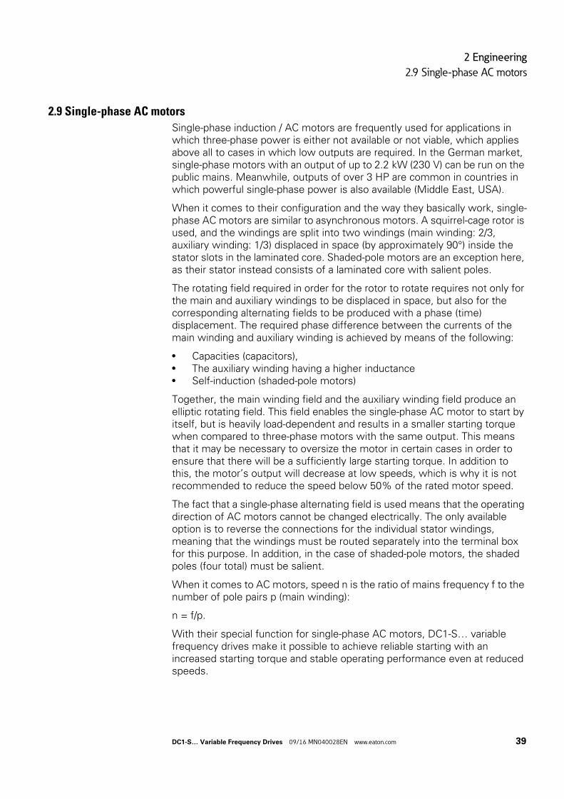
Figure 13: Shaded-pole motor
In shaded-pole motors, the magnetic field produced by the main winding (stator winding) induces a lagging magnetic field in the short-circuited shading coil (auxiliary winding), which is displaced in space. This elliptic rotating field is heavily load-dependent (slip of approximately 7 to 10 %) and is defined to a significant extent by the shaded poles’ saliency. Accordingly, the starting torque will only be around 25 to 70 % of the rated torque, while the efficiency will be approx. 30 %.
As a result of their design, shaded-pole motors cost less and have a much smaller frame size than capacitor-start/capacitor-run motors with a comparable output. Shaded-pole motors are used predominantly for short-time operation at outputs of up to approximately 300 W, and their quietness and long lifespan, combined with the fact that they are maintenance-free, make them the motor of choice for small, direct-drive axial and radial fans and blowers.
U V U V
M1∼
40 DC1-S… Variable Frequency Drives 09/16 MN040028EN www.eaton.com
2 Engineering
2.9 Single-phase AC motors
2.9.2 Split-phase motors
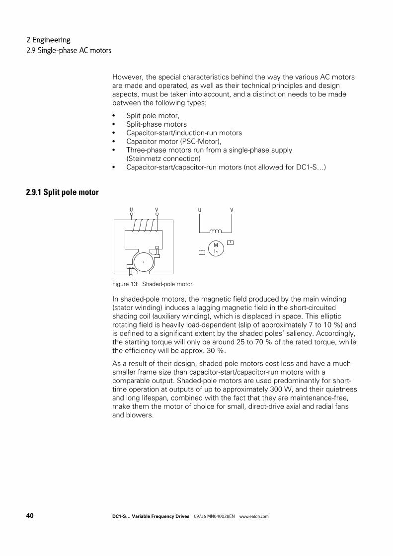
Figure 14: Split-phase motor
In split-phase motors, the windings inside the stator are displaced in space and have different inductances, ensuring that the current flow through these windings will produce the required phase difference in the magnetic fields (approximately 25 to 30°). Within this context, the main winding has a relatively low active resistance and a large reactance, while the start winding has a high active resistance and a relatively low reactance.
The start winding is (must be) automatically disconnected by a centrifugal switch (rotary switch) after about five seconds due to the risk of overheating, as well as to reduce power loss, at approx. 75 % of the rated speed. In applications involving refrigerator compressors, the start winding is instead disconnected by a solenoid switch based on current consumption. The starting torque will reach approximately 150 to 200 % of the rated torque, and the inrush current will be around 6 to 8 times the rated operational current.
After the start winding is disconnected, the motor will keep accelerating until it reaches its normal speed. This speed will be relatively constant and be approximately 2 to 5 % (slip) lower than the synchronous speed, depending on the motor’s load.
Typical areas of application involve motor outputs of up to 300 W (0.5 HP) with a stationary operating behavior. Examples include drives that are not switched on and off frequently and have a low starting torque, such as those used in small belt-drive or direct-drive machine tools, fans, compressors in refrigerators, washing machines, oil burners, small mills, etc.
~ RotarySwich
U
V
Rotaryswitch
n >
DC1-S… Variable Frequency Drives 09/16 MN040028EN www.eaton.com 41
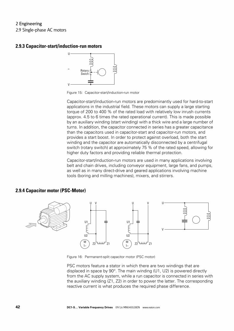
2 Engineering
2.9 Single-phase AC motors
2.9.3 Capacitor-start/induction-run motors
Figure 15: Capacitor-start/induction-run motor
Capacitor-start/induction-run motors are predominantly used for hard-to-start applications in the industrial field. These motors can supply a large starting torque of 200 to 400 % of the rated load with relatively low inrush currents (approx. 4.5 to 6 times the rated operational current). This is made possible by an auxiliary winding (start winding) with a thick wire and a large number of turns. In addition, the capacitor connected in series has a greater capacitance than the capacitors used in capacitor-start and capacitor-run motors, and provides a start boost. In order to protect against overload, both the start winding and the capacitor are automatically disconnected by a centrifugal switch (rotary switch) at approximately 75 % of the rated speed, allowing for higher duty factors and providing reliable thermal protection.
Capacitor-start/induction-run motors are used in many applications involving belt and chain drives, including conveyor equipment, large fans, and pumps, as well as in many direct-drive and geared applications involving machine tools (boring and milling machines), mixers, and stirrers.
2.9.4 Capacitor motor (PSC-Motor)
Figure 16: Permanent-split capacitor motor (PSC motor)
PSC motors feature a stator in which there are two windings that are displaced in space by 90°. The main winding (U1, U2) is powered directly from the AC supply system, while a run capacitor is connected in series with the auxiliary winding (Z1, Z2) in order to power the latter. The corresponding reactive current is what produces the required phase difference.
~ RotarySwich
U
V
U V
U1
U2
Z2 Z1M1∼
U V
U1
U2
Z2 Z1M1∼
U
V
42 DC1-S… Variable Frequency Drives 09/16 MN040028EN www.eaton.com
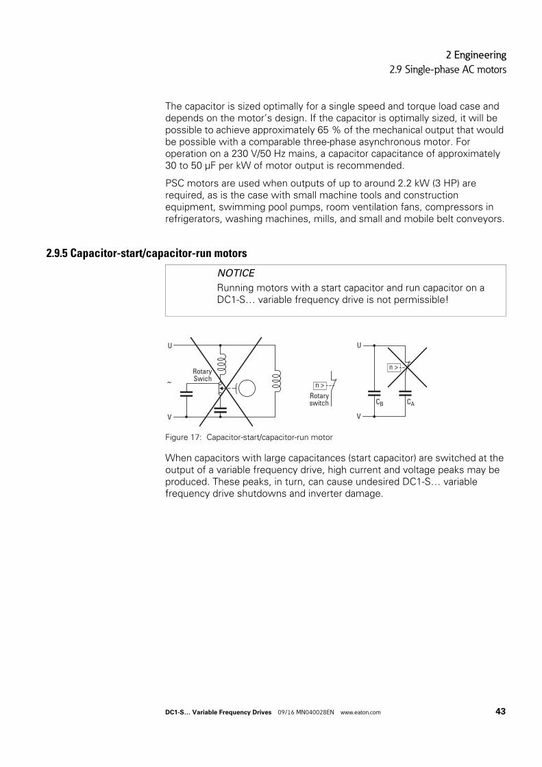
2 Engineering
2.9 Single-phase AC motors
The capacitor is sized optimally for a single speed and torque load case and depends on the motor’s design. If the capacitor is optimally sized, it will be possible to achieve approximately 65 % of the mechanical output that would be possible with a comparable three-phase asynchronous motor. For operation on a 230 V/50 Hz mains, a capacitor capacitance of approximately 30 to 50 μF per kW of motor output is recommended.
PSC motors are used when outputs of up to around 2.2 kW (3 HP) are required, as is the case with small machine tools and construction equipment, swimming pool pumps, room ventilation fans, compressors in refrigerators, washing machines, mills, and small and mobile belt conveyors.
2.9.5 Capacitor-start/capacitor-run motors
Figure 17: Capacitor-start/capacitor-run motor
When capacitors with large capacitances (start capacitor) are switched at the output of a variable frequency drive, high current and voltage peaks may be produced. These peaks, in turn, can cause undesired DC1-S… variable frequency drive shutdowns and inverter damage.
NOTICE
Running motors with a start capacitor and run capacitor on a DC1-S… variable frequency drive is not permissible!
U
V
~RotarySwich
Rotaryswitch
n >
U
V
CB CA
n >
DC1-S… Variable Frequency Drives 09/16 MN040028EN www.eaton.com 43
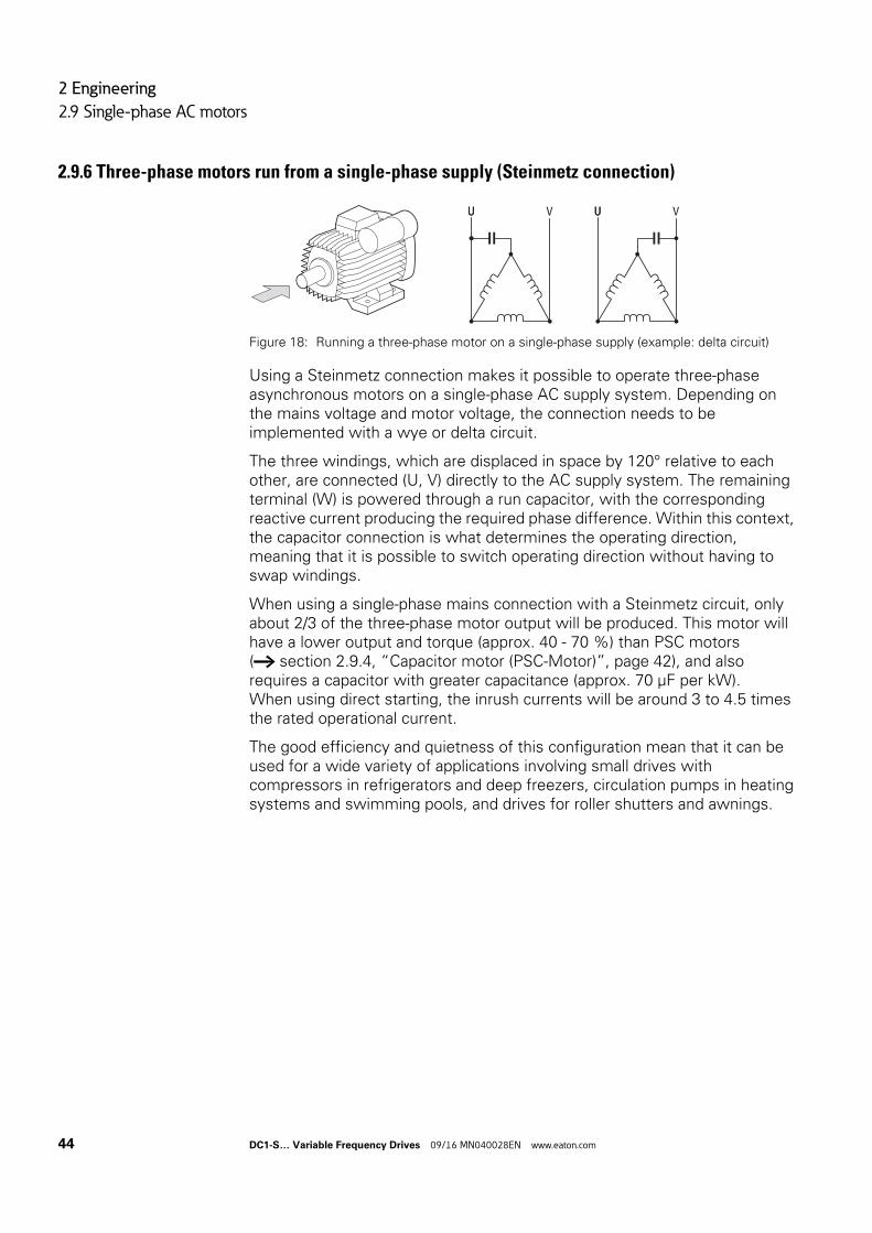
2 Engineering
2.9 Single-phase AC motors
2.9.6 Three-phase motors run from a single-phase supply (Steinmetz connection)
Figure 18: Running a three-phase motor on a single-phase supply (example: delta circuit)
Using a Steinmetz connection makes it possible to operate three-phase asynchronous motors on a single-phase AC supply system. Depending on the mains voltage and motor voltage, the connection needs to be implemented with a wye or delta circuit.
The three windings, which are displaced in space by 120° relative to each other, are connected (U, V) directly to the AC supply system. The remaining terminal (W) is powered through a run capacitor, with the corresponding reactive current producing the required phase difference. Within this context, the capacitor connection is what determines the operating direction, meaning that it is possible to switch operating direction without having to swap windings.
When using a single-phase mains connection with a Steinmetz circuit, only about 2/3 of the three-phase motor output will be produced. This motor will have a lower output and torque (approx. 40 - 70 %) than PSC motors (→ section 2.9.4, “Capacitor motor (PSC-Motor)”, page 42), and also requires a capacitor with greater capacitance (approx. 70 μF per kW). When using direct starting, the inrush currents will be around 3 to 4.5 times the rated operational current.
The good efficiency and quietness of this configuration mean that it can be used for a wide variety of applications involving small drives with compressors in refrigerators and deep freezers, circulation pumps in heating systems and swimming pools, and drives for roller shutters and awnings.
UU V UU V
44 DC1-S… Variable Frequency Drives 09/16 MN040028EN www.eaton.com
2 Engineering
2.9 Single-phase AC motors
2.9.7 Motor Selection
General recommendations for motor selection:
• Only use motors that have insulation class F (maximum steady state temperature of 155 °C ) at least.
• Take the operating conditions into account for S1 operation (IEC 60034-1).• Do not oversize the motor, i.e., the motor should not be more than one
rating level higher than the rated motor output for the variable frequency drive.
• In the case of undersized motors, the motor output for continuous operation should not be more than one rating level lower than the variable frequency drive’s rated rating level (in order to ensure that the motor will be protected).
• When running tests or commissioning a system with significantly lower motor outputs, the motor’s rated operational current must be adjusted using parameter P-08 (“rated motor current”).
2.9.8 Connecting EX motorsThe following aspects must be taken into account when connecting hazardous location motors:
• A DC1-S… variable frequency drive can be installed in an explosion-proof enclosure within the hazardous location or in a control panel outside the hazardous location.
• All applicable industry-specific and country-specific regulations for hazardous locations (ATEX 100a) must be complied with.
• The specifications and instructions provided by the motor’s manufacturer with regard to operation with a variable frequency drive must be taken into account.
• Temperature sensors in the motor windings (thermistor, Thermo-Click) must not be connected directly to the variable frequency drive, but instead must be connected through a relay approved for the hazardous location (e.g. EMT6).
→ Check whether the DC1-S… variable frequency drive you selected and the single-phase AC motor you will be using are compatible with each other as per the corresponding voltage (mains and motor voltage) and rated operational current.
DC1-S… Variable Frequency Drives 09/16 MN040028EN www.eaton.com 45

2 Engineering
2.9 Single-phase AC motors
46 DC1-S… Variable Frequency Drives 09/16 MN040028EN www.eaton.com
3 Installation
3.1 Introduction
3 Installation
3.1 IntroductionThis chapter provides a description of the installation and the electrical connections for the variable frequency drive DC1-S… series.
3.2 Mounting positionDC1-S…CE1 variable frequency drives have a conformal coating on their printed circuit boards (coated boards) that provides enhanced protection from moisture and soiling.
DC1-S… variable frequency drives are available with two enclosure versions:
• IP20 / NEMA 0 degree of protection: for use in control panels.• IP66 / NEMA 4X protection type: This enclosure version protects against
moisture and dust and is designed for use in harsh conditions.
Without the required additional measures, using the device in the following environments is strictly prohibited:
• Explosion-proof Ranges• Environments with damaging substances:
• Oils and acids• Gases and fumes• Dust• Radiated noise
• Environments with mechanical vibration and impact loads that go beyond the requirements in IEC/EN 61800-5-1.
• Areas in which the variable frequency drive takes care of safety functions that must guarantee machine and personnel protection.
→ While installing and/or assembling the variable frequency drive, cover all ventilation slots in order to ensure that no foreign bodies can enter the device.
→ Perform all installation work with the specified tools and without the use of excessive force.
→ For more information on how to install DC1-S… variable frequency drives with the various available degrees of protection and frame sizes, please refer to the following instruction leaflets:
• IL04020014Z (IP20 in sizes FS1 and FS2)• IL040001ZU (IP66 in sizes FS1 and FS2)
DC1-S… Variable Frequency Drives 09/16 MN040028EN www.eaton.com 47
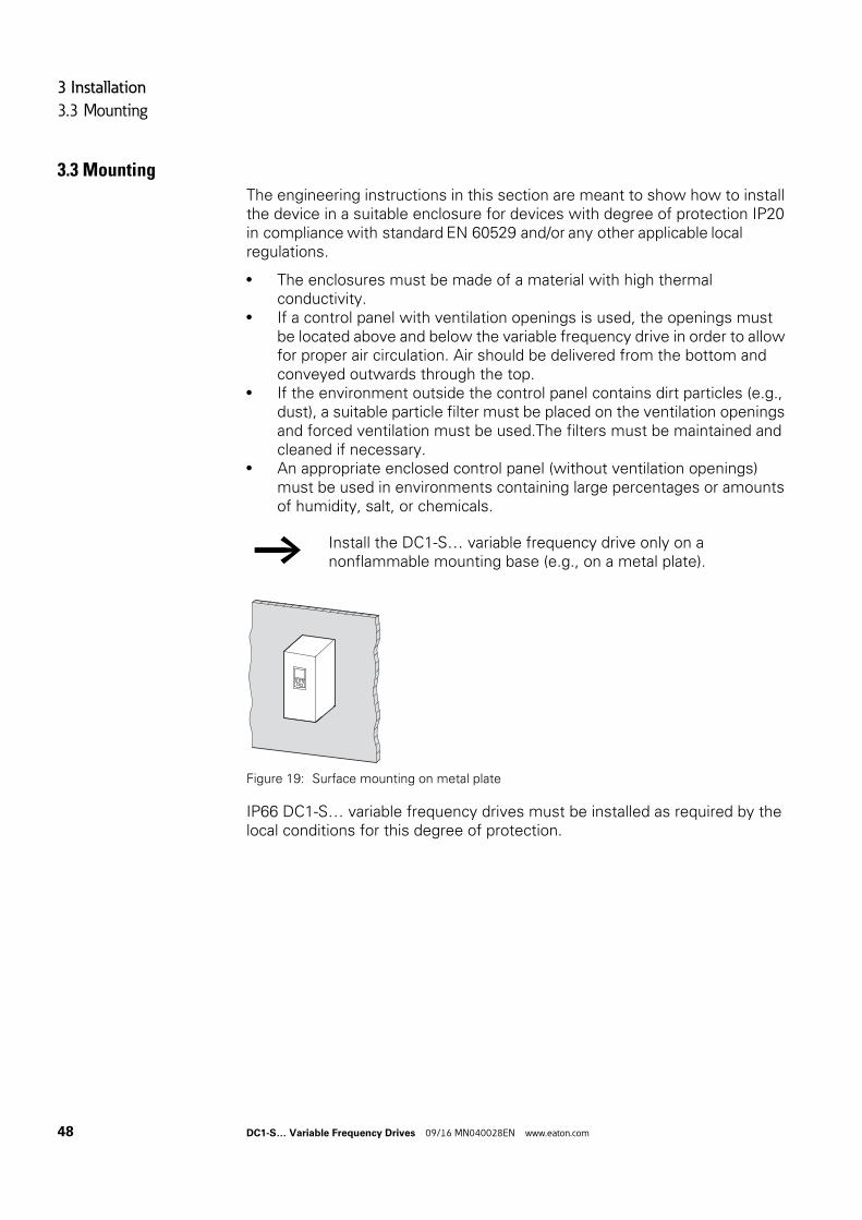
3 Installation
3.3 Mounting
3.3 Mounting
The engineering instructions in this section are meant to show how to install the device in a suitable enclosure for devices with degree of protection IP20 in compliance with standard EN 60529 and/or any other applicable local regulations.
• The enclosures must be made of a material with high thermal conductivity.
• If a control panel with ventilation openings is used, the openings must be located above and below the variable frequency drive in order to allow for proper air circulation. Air should be delivered from the bottom and conveyed outwards through the top.
• If the environment outside the control panel contains dirt particles (e.g., dust), a suitable particle filter must be placed on the ventilation openings and forced ventilation must be used.The filters must be maintained and cleaned if necessary.
• An appropriate enclosed control panel (without ventilation openings) must be used in environments containing large percentages or amounts of humidity, salt, or chemicals.
Figure 19: Surface mounting on metal plate
IP66 DC1-S… variable frequency drives must be installed as required by the local conditions for this degree of protection.
→ Install the DC1-S… variable frequency drive only on a nonflammable mounting base (e.g., on a metal plate).
48 DC1-S… Variable Frequency Drives 09/16 MN040028EN www.eaton.com
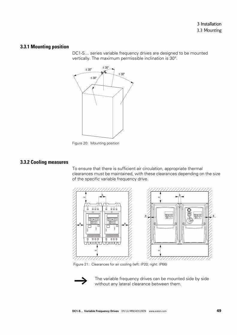
3 Installation
3.3 Mounting
3.3.1 Mounting positionDC1-S… series variable frequency drives are designed to be mounted vertically. The maximum permissible inclination is 30°.
Figure 20: Mounting position
3.3.2 Cooling measuresTo ensure that there is sufficient air circulation, appropriate thermal clearances must be maintained, with these clearances depending on the size of the specific variable frequency drive.
≦ 30º
≦ 30º
≦ 30º
≦ 30º
Figure 21: Clearances for air cooling (left: IP20; right: IP66)
→ The variable frequency drives can be mounted side by side without any lateral clearance between them.
b
c
a
c
a
1 2 3 4 5 6 7 8 9 10 11 1 2 3 4 5 6 7 8 9 10 11
c
a
c
REV FWD0
ON
OFFPWR
b
a
DC1-S… Variable Frequency Drives 09/16 MN040028EN www.eaton.com 49
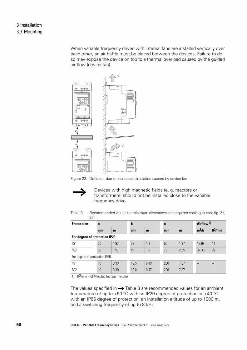
3 Installation
3.3 Mounting
When variable frequency drives with internal fans are installed vertically over each other, an air baffle must be placed between the devices. Failure to do so may expose the device on top to a thermal overload caused by the guided air flow (device fan).
Figure 22: Deflector due to increased circulation caused by device fan
Table 3: Recommended values for minimum clearances and required cooling air (see fig. 21, 22)
The values specified in → Table 3 are recommended values for an ambient temperature of up to +50 °C with an IP20 degree of protection or +40 °C with an IP66 degree of protection, an installation altitude of up to 1000 m, and a switching frequency of up to 8 kHz.
→ Devices with high magnetic fields (e. g. reactors or transformers) should not be installed close to the variable frequency drive.
Frame size a b c Airflow1)
mm in mm in mm in m3/h ft3/min
For degree of protection IP20
FS1 50 1.97 33 1.3 50 1.97 18.69 11
FS2 50 1.97 46 1.81 75 2.95 37.38 22
For degree of protection IP66
FS1 10 0.39 12.5 0.49 200 7.87 – –
FS2 10 0.39 12.0 0.47 200 7.87 – –
1) ft3/min = CFM (cubic foot per minute)
cc
V
V
VAR
EMC
50 DC1-S… Variable Frequency Drives 09/16 MN040028EN www.eaton.com
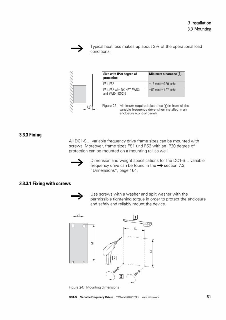
3 Installation
3.3 Mounting
3.3.3 FixingAll DC1-S… variable frequency drive frame sizes can be mounted with screws. Moreover, frame sizes FS1 und FS2 with an IP20 degree of protection can be mounted on a mounting rail as well.
3.3.3.1 Fixing with screws
→ Typical heat loss makes up about 3% of the operational load conditions.
① Figure 23: Minimum required clearance ① in front of the variable frequency drive when installed in an enclosure (control panel)
Size with IP20 degree of protection
Minimum clearance ①
FS1, FS2 ≧ 15 mm (≧ 0.59 inch)
FS1, FS2 with DX-NET-SWD3 and SWD4-8SF2-5
≧ 50 mm (≧ 1.97 inch)
→ Dimension and weight specifications for the DC1-S… variable frequency drive can be found in the → section 7.3, “Dimensions”, page 164.
→ Use screws with a washer and split washer with the permissible tightening torque in order to protect the enclosure and safely and reliably mount the device.
Figure 24: Mounting dimensions
b1
a1 1
2
3
b1
a1
DC1-S… Variable Frequency Drives 09/16 MN040028EN www.eaton.com 51
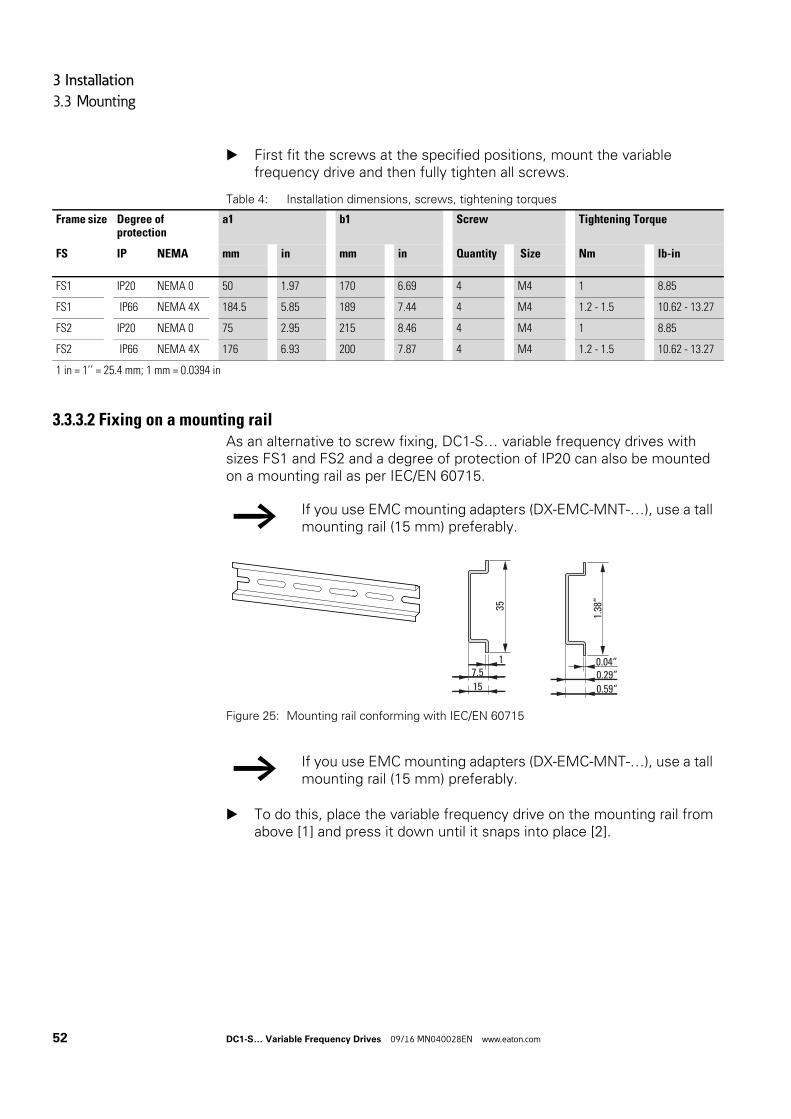
3 Installation
3.3 Mounting
First fit the screws at the specified positions, mount the variable frequency drive and then fully tighten all screws.
Table 4: Installation dimensions, screws, tightening torques
3.3.3.2 Fixing on a mounting railAs an alternative to screw fixing, DC1-S… variable frequency drives with sizes FS1 and FS2 and a degree of protection of IP20 can also be mounted on a mounting rail as per IEC/EN 60715.
Figure 25: Mounting rail conforming with IEC/EN 60715
To do this, place the variable frequency drive on the mounting rail from above [1] and press it down until it snaps into place [2].
Frame size Degree of protection
a1 b1 Screw Tightening Torque
FS IP NEMA mm in mm in Quantity Size Nm lb-in
FS1 IP20 NEMA 0 50 1.97 170 6.69 4 M4 1 8.85
FS1 IP66 NEMA 4X 184.5 5.85 189 7.44 4 M4 1.2 - 1.5 10.62 - 13.27
FS2 IP20 NEMA 0 75 2.95 215 8.46 4 M4 1 8.85
FS2 IP66 NEMA 4X 176 6.93 200 7.87 4 M4 1.2 - 1.5 10.62 - 13.27
1 in = 1’’ = 25.4 mm; 1 mm = 0.0394 in
→ If you use EMC mounting adapters (DX-EMC-MNT-…), use a tall mounting rail (15 mm) preferably.
→ If you use EMC mounting adapters (DX-EMC-MNT-…), use a tall mounting rail (15 mm) preferably.
35
17.515
1.38
”
0.04”0.29”0.59”
52 DC1-S… Variable Frequency Drives 09/16 MN040028EN www.eaton.com
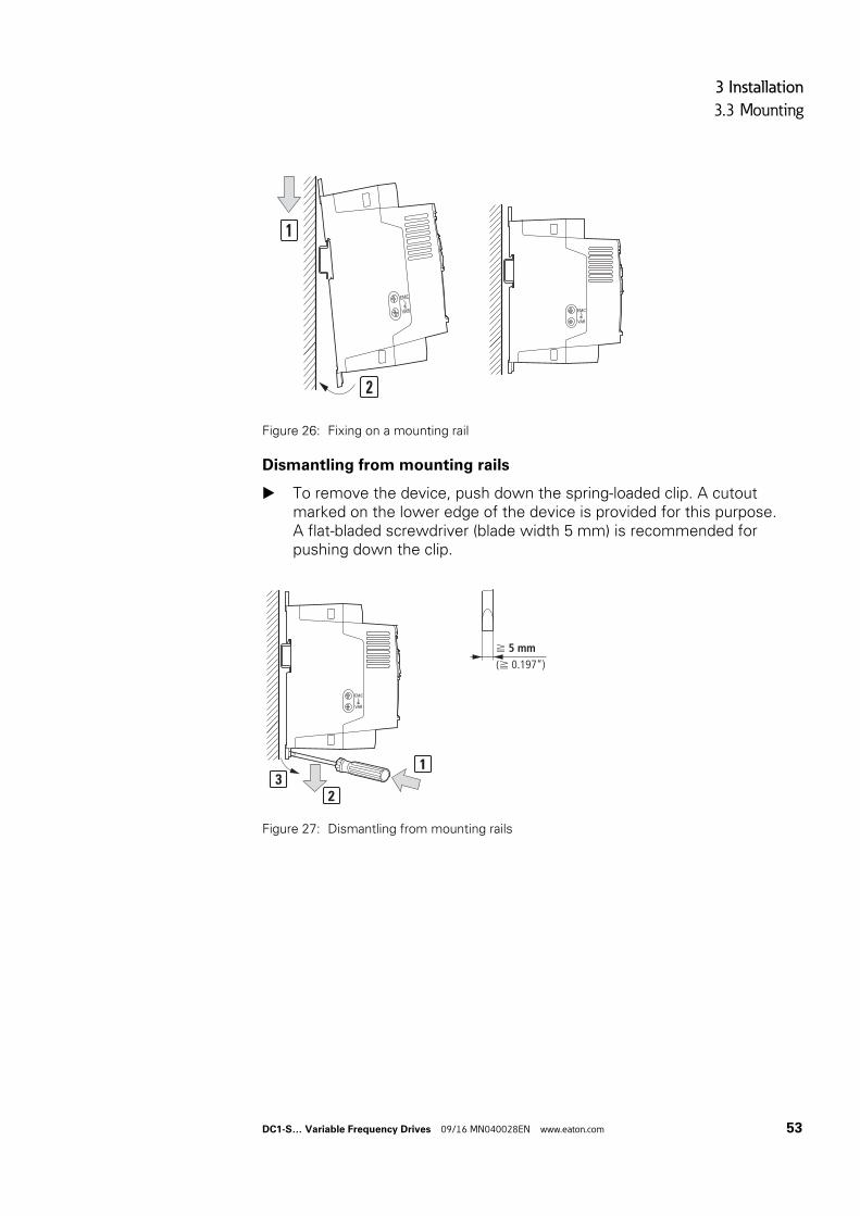
3 Installation
3.3 Mounting
Figure 26: Fixing on a mounting rail
Dismantling from mounting rails
To remove the device, push down the spring-loaded clip. A cutout marked on the lower edge of the device is provided for this purpose.A flat-bladed screwdriver (blade width 5 mm) is recommended for pushing down the clip.
Figure 27: Dismantling from mounting rails
2
1
VAR
EMC
VAR
EMC
2
13
VAR
EMC
f 5 mm(f 0.197“)
DC1-S… Variable Frequency Drives 09/16 MN040028EN www.eaton.com 53
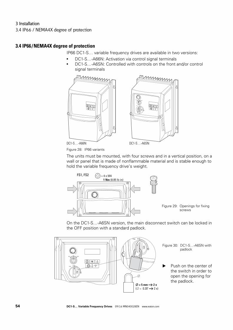
3 Installation
3.4 IP66 / NEMA4X degree of protection
3.4 IP66 / NEMA4X degree of protection
IP66 DC1-S… variable frequency drives are available in two versions:
• DC1-S…-A66N: Activation via control signal terminals• DC1-S…-A6SN: Controlled with controls on the front and/or control
signal terminals
Figure 28: IP66 variants
The units must be mounted, with four screws and in a vertical position, on a wall or panel that is made of nonflammable material and is stable enough to hold the variable frequency drive’s weight.
On the DC1-S…-A6SN version, the main disconnect switch can be locked in the OFF position with a standard padlock.
DC1-S…-A66N DC1-S…-A6SN
Figure 29: Openings for fixing screws
PWR OFF
ON
REVFWD
0
= 4 x M4 1 Nm (8.85 lb-in)
FS1, FS2
Figure 30: DC1-S…-A6SN with padlock
Push on the center of the switch in order to open the opening for the padlock.
PWR OFF
ON
REV FWD0
ON
OFFPWR
= 5 mm → 2 x
( = 0.20" → 2 x)
54 DC1-S… Variable Frequency Drives 09/16 MN040028EN www.eaton.com
3 Installation
3.5 EMC installation
3.5 EMC installation
The responsibility to comply with the legally stipulated limit values and thus the provision of electromagnetic compatibility is the responsibility of the end user or system operator. This operator must also take measures to minimize or remove emission in the environment concerned. He must also utilize means to increase the interference immunity of the devices of the system.
The technology and system of a variable frequency drive cause the flow of high frequency leakage current during operation. Because of this, all earthing elements must be low-impedance elements connected in such a way as to establish an electrical contact across a large surface area.
With leakage currents greater than 3.5 mA, in accordance withIEC/EN 61800-5-1 or EN 60335, either
• the cable cross-section of the protective conductor must be ≧ 10 mm2,• the protective conductor must be open-circuit monitored, or• the second protective conductor must be fitted.
For an EMC-compliant installation, we recommend the following measures:
• installation of the variable frequency drive in a metallically conductive housing with a good connection to ground,
• screened motor cables (short cables).
3.5.1 EMC measures in the control panelIn order to have an installation that meets EMC requirements, make sure to connect all the metallic parts in the devices and in the control panel to each other across a large area and in a way that will make it possible to conduct high frequencies. Mounting plates and control panel doors should be connected to the panel by means of short drain wires with an electrical contact established across a large surface area.
→ In a magnet system (PDS) with variable frequency drives, you should take measures for electromagnetic compatibility (EMC) while doing your engineering, since changes or improvements to the installation site, which are required in the installation or while mounting, are normally associated with additional higher costs as well.
→ Ground all conductive components and housings in a drive system using as short a line as possible with the greatest possible cross-section (Cu-braid).
→ Do not make connections to painted surfaces (electrolytic oxidation, yellow chromated).
→ Install the variable frequency drive as directly as possible (without spacers) on a metal plate (mounting plate).
DC1-S… Variable Frequency Drives 09/16 MN040028EN www.eaton.com 55
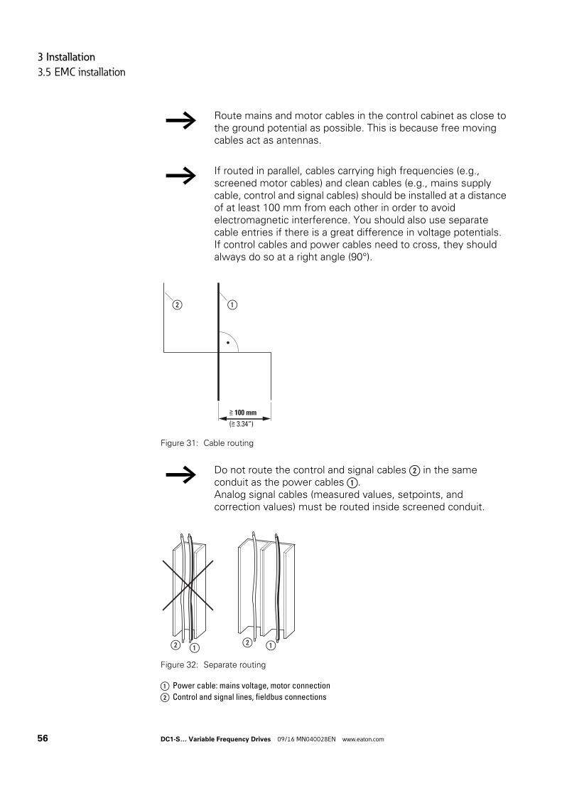
3 Installation
3.5 EMC installation
Figure 31: Cable routing
Figure 32: Separate routing
a Power cable: mains voltage, motor connection
b Control and signal lines, fieldbus connections
→ Route mains and motor cables in the control cabinet as close to the ground potential as possible. This is because free moving cables act as antennas.
→ If routed in parallel, cables carrying high frequencies (e.g., screened motor cables) and clean cables (e.g., mains supply cable, control and signal cables) should be installed at a distance of at least 100 mm from each other in order to avoid electromagnetic interference. You should also use separate cable entries if there is a great difference in voltage potentials. If control cables and power cables need to cross, they should always do so at a right angle (90°).
→ Do not route the control and signal cables ② in the same conduit as the power cables ①.Analog signal cables (measured values, setpoints, and correction values) must be routed inside screened conduit.
≧ 100 mm
(≧ 3.34“)
② ①
abab
56 DC1-S… Variable Frequency Drives 09/16 MN040028EN www.eaton.com
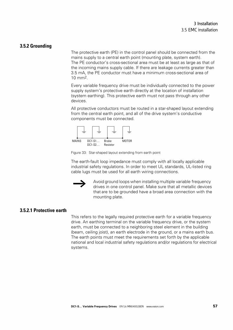
3 Installation
3.5 EMC installation
3.5.2 GroundingThe protective earth (PE) in the control panel should be connected from the mains supply to a central earth point (mounting plate, system earth).The PE conductor’s cross-sectional area must be at least as large as that of the incoming mains supply cable. If there are leakage currents greater than 3.5 mA, the PE conductor must have a minimum cross-sectional area of 10 mm2.
Every variable frequency drive must be individually connected to the power supply system’s protective earth directly at the location of installation (system earthing). This protective earth must not pass through any other devices.
All protective conductors must be routed in a star-shaped layout extending from the central earth point, and all of the drive system’s conductive components must be connected.
Figure 33: Star-shaped layout extending from earth point
The earth-fault loop impedance must comply with all locally applicable industrial safety regulations. In order to meet UL standards, UL-listed ring cable lugs must be used for all earth wiring connections.
3.5.2.1 Protective earthThis refers to the legally required protective earth for a variable frequency drive. An earthing terminal on the variable frequency drive, or the system earth, must be connected to a neighboring steel element in the building (beam, ceiling joist), an earth electrode in the ground, or a mains earth bus. The earth points must meet the requirements set forth by the applicable national and local industrial safety regulations and/or regulations for electrical systems.
→ Avoid ground loops when installing multiple variable frequency drives in one control panel. Make sure that all metallic devices that are to be grounded have a broad area connection with the mounting plate.
MOTORBrake Resistor
MAINS DC1-S1…DC1-S2…
DC1-S… Variable Frequency Drives 09/16 MN040028EN www.eaton.com 57
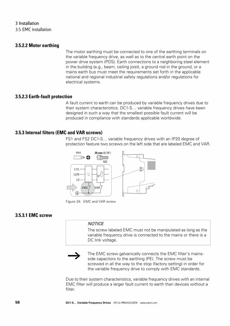
3 Installation
3.5 EMC installation
3.5.2.2 Motor earthingThe motor earthing must be connected to one of the earthing terminals on the variable frequency drive, as well as to the central earth point on the power drive system (PDS). Earth connections to a neighboring steel element in the building (e.g., beam, ceiling joist), a ground rod in the ground, or a mains earth bus must meet the requirements set forth in the applicable national and regional industrial safety regulations and/or regulations for electrical systems.
3.5.2.3 Earth-fault protectionA fault current to earth can be produced by variable frequency drives due to their system characteristics. DC1-S… variable frequency drives have been designed in such a way that the smallest possible fault current will be produced in compliance with standards applicable worldwide.
3.5.3 Internal filters (EMC and VAR screws)FS1 and FS2 DC1-S… variable frequency drives with an IP20 degree of protection feature two screws on the left side that are labeled EMC and VAR.
Figure 34: EMC and VAR screw
3.5.3.1 EMC screw
Due to their system characteristics, variable frequency drives with an internal EMC filter will produce a larger fault current to earth than devices without a filter.
EMC
L3UL2/N
L1/L
VAR
PH1
M3
20 mm (0.79")
EMC
VAR
NOTICE
The screw labeled EMC must not be manipulated as long as the variable frequency drive is connected to the mains or there is a DC link voltage.
→ The EMC screw galvanically connects the EMC filter’s mains-side capacitors to the earthing (PE). The screw must be screwed in all the way to the stop (factory setting) in order for the variable frequency drive to comply with EMC standards.
58 DC1-S… Variable Frequency Drives 09/16 MN040028EN www.eaton.com
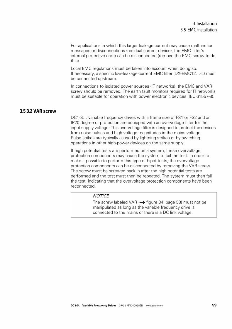
3 Installation
3.5 EMC installation
For applications in which this larger leakage current may cause malfunction messages or disconnections (residual current device), the EMC filter’s internal protective earth can be disconnected (remove the EMC screw to do this).
Local EMC regulations must be taken into account when doing so. If necessary, a specific low-leakage-current EMC filter (DX-EMC12…-L) must be connected upstream.
In connections to isolated power sources (IT networks), the EMC and VAR screw should be removed. The earth fault monitors required for IT networks must be suitable for operation with power electronic devices (IEC 61557-8).
3.5.3.2 VAR screwDC1-S… variable frequency drives with a frame size of FS1 or FS2 and an IP20 degree of protection are equipped with an overvoltage filter for the input supply voltage. This overvoltage filter is designed to protect the devices from noise pulses and high voltage magnitudes in the mains voltage. Pulse spikes are typically caused by lightning strikes or by switching operations in other high-power devices on the same supply.
If high potential tests are performed on a system, these overvoltage protection components may cause the system to fail the test. In order to make it possible to perform this type of hipot tests, the overvoltage protection components can be disconnected by removing the VAR screw. The screw must be screwed back in after the high potential tests are performed and the test must then be repeated. The system must then fail the test, indicating that the overvoltage protection components have been reconnected.
NOTICE
The screw labeled VAR (→ figure 34, page 58) must not be manipulated as long as the variable frequency drive is connected to the mains or there is a DC link voltage.
DC1-S… Variable Frequency Drives 09/16 MN040028EN www.eaton.com 59
3 Installation
3.5 EMC installation
3.5.4 Screen earth kitCables that are not screened work like antennas (sending, receiving).
The effectiveness of the cable screen depends on a good screen connection and a low screen impedance.
→ For a proper EMC connection, cables emitting interference (e.g. motor cables) and susceptible cables (analog signal and measured values) must be screened and laid separately from each other.
→ Use only screens with tinned or nickel-plated copper braiding. Screens made of steel braids or metal conduits are either not suitable or suitable only to a limited extent (depending on the EMC environment).
→ Control and signal lines (analog, digital) should always be grounded on one end, in the immediate vicinity of the supply voltage source (PES).
60 DC1-S… Variable Frequency Drives 09/16 MN040028EN www.eaton.com
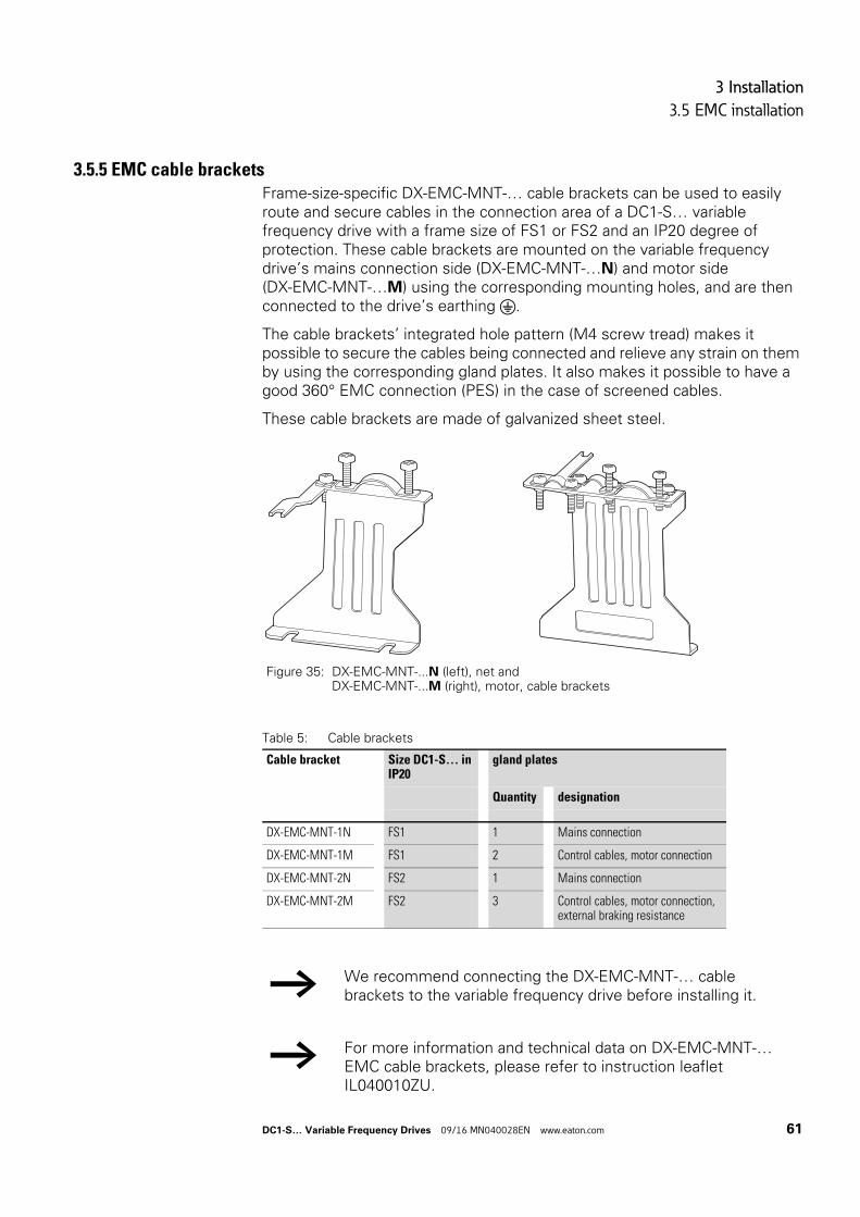
3 Installation
3.5 EMC installation
3.5.5 EMC cable bracketsFrame-size-specific DX-EMC-MNT-… cable brackets can be used to easily route and secure cables in the connection area of a DC1-S… variable frequency drive with a frame size of FS1 or FS2 and an IP20 degree of protection. These cable brackets are mounted on the variable frequency drive’s mains connection side (DX-EMC-MNT-…N) and motor side (DX-EMC-MNT-…M) using the corresponding mounting holes, and are then connected to the drive’s earthing .
The cable brackets’ integrated hole pattern (M4 screw tread) makes it possible to secure the cables being connected and relieve any strain on them by using the corresponding gland plates. It also makes it possible to have a good 360° EMC connection (PES) in the case of screened cables.
These cable brackets are made of galvanized sheet steel.
Table 5: Cable brackets
Figure 35: DX-EMC-MNT-...N (left), net and DX-EMC-MNT-...M (right), motor, cable brackets
Cable bracket Size DC1-S… in IP20
gland plates
Quantity designation
DX-EMC-MNT-1N FS1 1 Mains connection
DX-EMC-MNT-1M FS1 2 Control cables, motor connection
DX-EMC-MNT-2N FS2 1 Mains connection
DX-EMC-MNT-2M FS2 3 Control cables, motor connection, external braking resistance
→ We recommend connecting the DX-EMC-MNT-… cable brackets to the variable frequency drive before installing it.
→ For more information and technical data on DX-EMC-MNT-… EMC cable brackets, please refer to instruction leaflet IL040010ZU.
DC1-S… Variable Frequency Drives 09/16 MN040028EN www.eaton.com 61
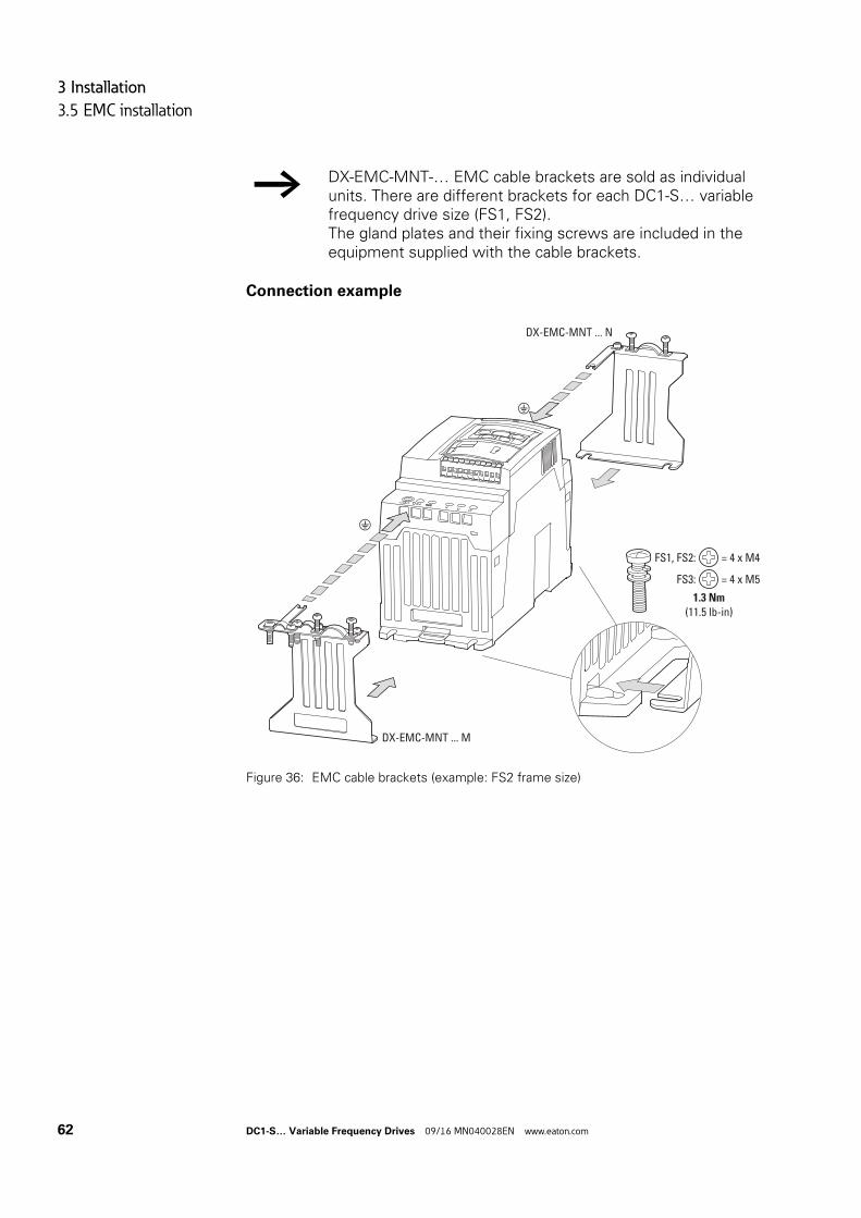
3 Installation
3.5 EMC installation
Connection example
Figure 36: EMC cable brackets (example: FS2 frame size)
→ DX-EMC-MNT-… EMC cable brackets are sold as individual units. There are different brackets for each DC1-S… variable frequency drive size (FS1, FS2).The gland plates and their fixing screws are included in the equipment supplied with the cable brackets.
1.3 Nm
(11.5 lb-in)
FS1, FS2: = 4 x M4
FS3: = 4 x M5
DX-EMC-MNT ... N
DX-EMC-MNT ... M
62 DC1-S… Variable Frequency Drives 09/16 MN040028EN www.eaton.com
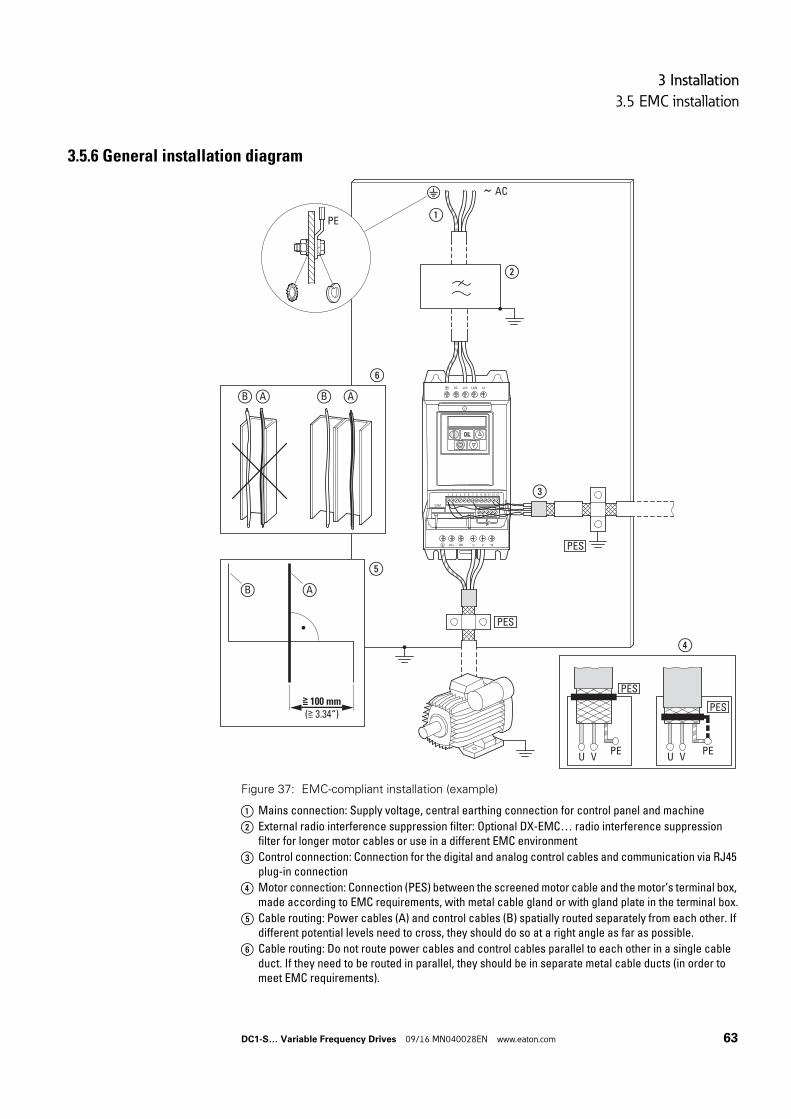
3 Installation
3.5 EMC installation
3.5.6 General installation diagram
Figure 37: EMC-compliant installation (example)
a Mains connection: Supply voltage, central earthing connection for control panel and machine
b External radio interference suppression filter: Optional DX-EMC… radio interference suppression filter for longer motor cables or use in a different EMC environment
c Control connection: Connection for the digital and analog control cables and communication via RJ45 plug-in connection
d Motor connection: Connection (PES) between the screened motor cable and the motor’s terminal box, made according to EMC requirements, with metal cable gland or with gland plate in the terminal box.
e Cable routing: Power cables (A) and control cables (B) spatially routed separately from each other. If different potential levels need to cross, they should do so at a right angle as far as possible.
f Cable routing: Do not route power cables and control cables parallel to each other in a single cable duct. If they need to be routed in parallel, they should be in separate metal cable ducts (in order to meet EMC requirements).
L2/N L3DC- L1/L
DC+ BR U V W
1 2 3 4 5 6 7 8 9 10 11 12 13
14 15 16 17 18
COM
~ AC
PES
PES
PE
≧ 100 mm
(≧ 3.34“)
PES
U VPE
U V
PES
PE
B A
⑤
⑥
AB AB
④
①
②
③
DC1-S… Variable Frequency Drives 09/16 MN040028EN www.eaton.com 63
3 Installation
3.6 Electrical Installation
3.6 Electrical Installation
CAUTION
Carry out wiring work only after the variable frequency drive has been correctly mounted and secured.
DANGER
Electric shock hazard - risk of injuries!Carry out wiring work only if the unit is de-energized.
NOTICE
Fire hazard!Only use cables, circuit-breakers, and contactors that feature the indicated permissible nominal current value.
NOTICE
On DC1-S… variable frequency drives, earth leakage currents can be greater than 3.5 mA (AC). Accordingly, as per IEC/EN 61800-5-1, an additional protective conductor must be connected or the protective conductor’s cross-sectional area must be at least 10 mm2.
DANGER
The components in the variable frequency drive’s power section remain energized up to five (5) minutes after the supply voltage has been switched off (intermediate circuit capacitor discharging time).
Pay attention to hazard warnings!.
→ Complete the following steps with the specified tools and without using force.
64 DC1-S… Variable Frequency Drives 09/16 MN040028EN www.eaton.com
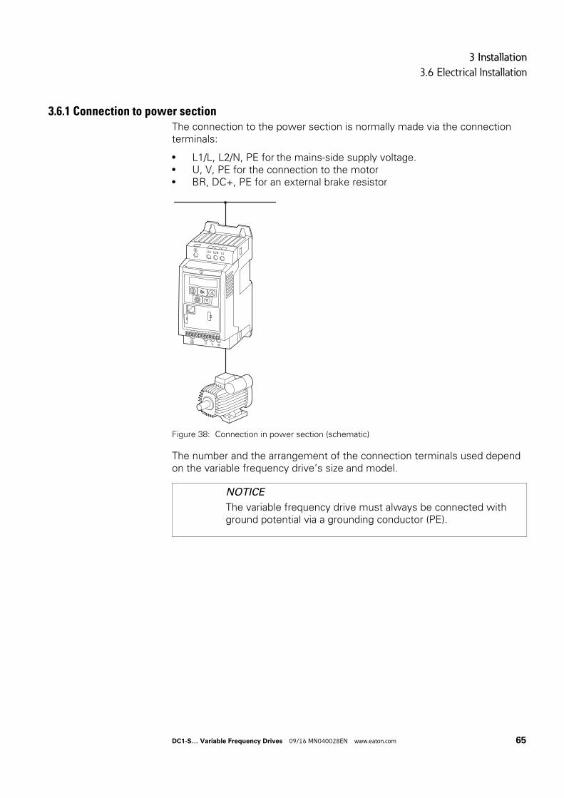
3 Installation
3.6 Electrical Installation
3.6.1 Connection to power sectionThe connection to the power section is normally made via the connection terminals:
• L1/L, L2/N, PE for the mains-side supply voltage.• U, V, PE for the connection to the motor• BR, DC+, PE for an external brake resistor
Figure 38: Connection in power section (schematic)
The number and the arrangement of the connection terminals used depend on the variable frequency drive’s size and model.
NOTICE
The variable frequency drive must always be connected with ground potential via a grounding conductor (PE).
L1/L L2/N L3
U V W
1 2 3 4 5 6 7 8 9 10 11
DC1-S… Variable Frequency Drives 09/16 MN040028EN www.eaton.com 65
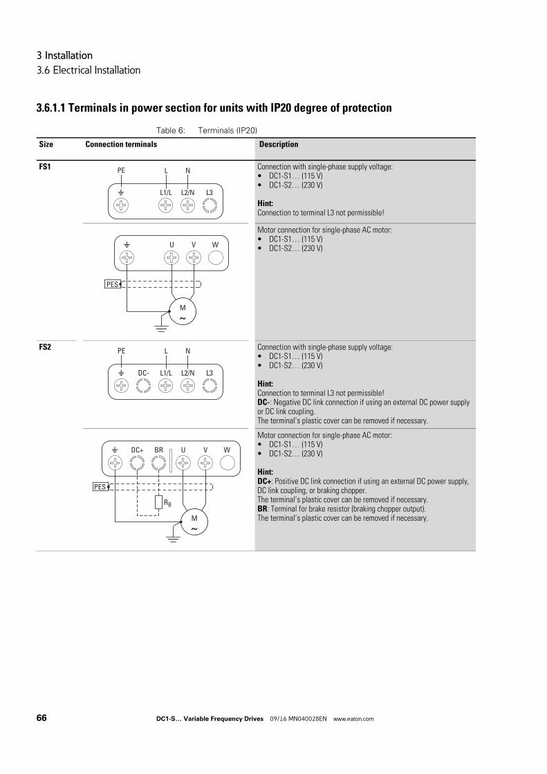
3 Installation
3.6 Electrical Installation
3.6.1.1 Terminals in power section for units with IP20 degree of protection
Table 6: Terminals (IP20)
Size Connection terminals Description
FS1 Connection with single-phase supply voltage:• DC1-S1… (115 V)• DC1-S2… (230 V)
Hint:Connection to terminal L3 not permissible!
Motor connection for single-phase AC motor:• DC1-S1… (115 V)• DC1-S2… (230 V)
FS2 Connection with single-phase supply voltage:• DC1-S1… (115 V)• DC1-S2… (230 V)
Hint:Connection to terminal L3 not permissible!DC-: Negative DC link connection if using an external DC power supply or DC link coupling.The terminal’s plastic cover can be removed if necessary.
Motor connection for single-phase AC motor:• DC1-S1… (115 V)• DC1-S2… (230 V)
Hint:DC+: Positive DC link connection if using an external DC power supply, DC link coupling, or braking chopper.The terminal’s plastic cover can be removed if necessary.BR: Terminal for brake resistor (braking chopper output).The terminal’s plastic cover can be removed if necessary.
L1/L L2/N L3
L NPE
U V W
PES
M
DC- L1/L L2/N L3
L NPE
PES
DC+ BR U V W
RB
M
66 DC1-S… Variable Frequency Drives 09/16 MN040028EN www.eaton.com
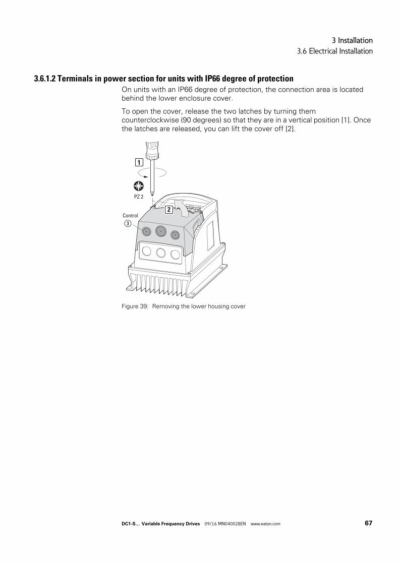
3 Installation
3.6 Electrical Installation
3.6.1.2 Terminals in power section for units with IP66 degree of protectionOn units with an IP66 degree of protection, the connection area is located behind the lower enclosure cover.
To open the cover, release the two latches by turning them counterclockwise (90 degrees) so that they are in a vertical position [1]. Once the latches are released, you can lift the cover off [2].
Figure 39: Removing the lower housing cover
③Control
PZ 2
1
2
DC1-S… Variable Frequency Drives 09/16 MN040028EN www.eaton.com 67
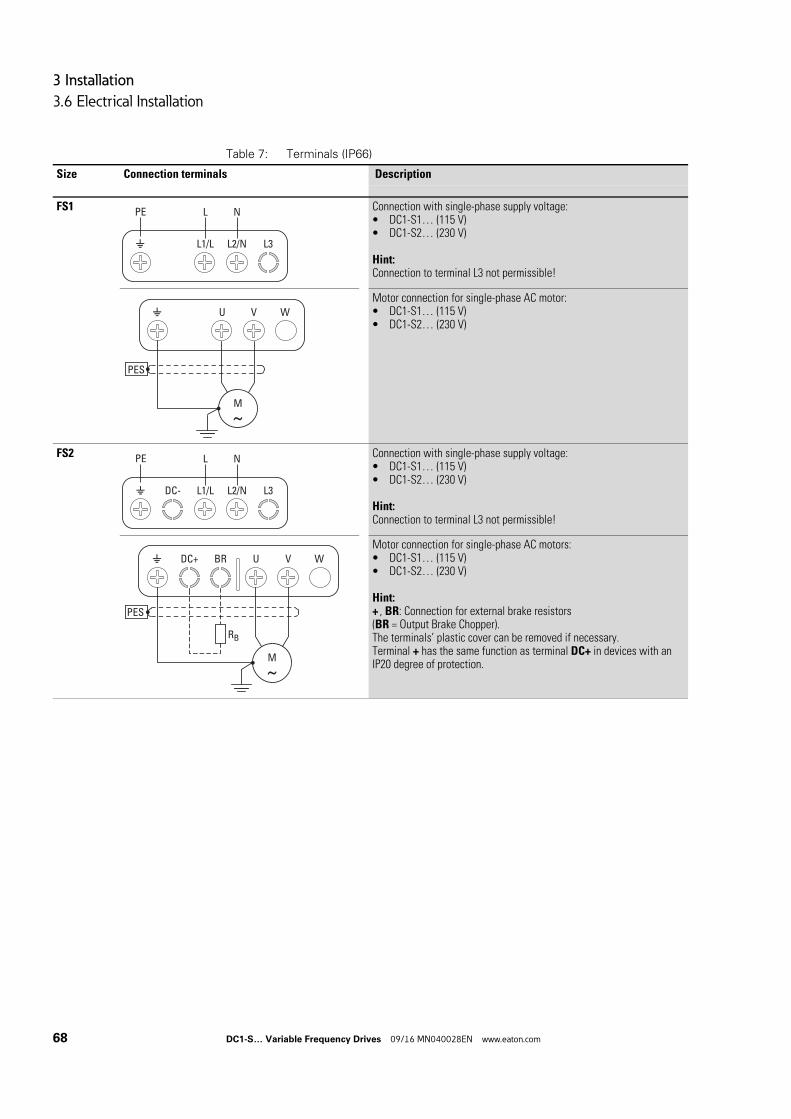
3 Installation
3.6 Electrical Installation
Table 7: Terminals (IP66)
Size Connection terminals Description
FS1 Connection with single-phase supply voltage:• DC1-S1… (115 V)• DC1-S2… (230 V)
Hint:Connection to terminal L3 not permissible!
Motor connection for single-phase AC motor:• DC1-S1… (115 V)• DC1-S2… (230 V)
FS2 Connection with single-phase supply voltage:• DC1-S1… (115 V)• DC1-S2… (230 V)
Hint:Connection to terminal L3 not permissible!
Motor connection for single-phase AC motors:• DC1-S1… (115 V)• DC1-S2… (230 V)
Hint:+ , BR: Connection for external brake resistors(BR = Output Brake Chopper).The terminals’ plastic cover can be removed if necessary.Terminal + has the same function as terminal DC+ in devices with an IP20 degree of protection.
L1/L L2/N L3
L NPE
U V W
PES
M
DC- L1/L L2/N L3
L NPE
PES
DC+ BR U V W
RB
M
68 DC1-S… Variable Frequency Drives 09/16 MN040028EN www.eaton.com
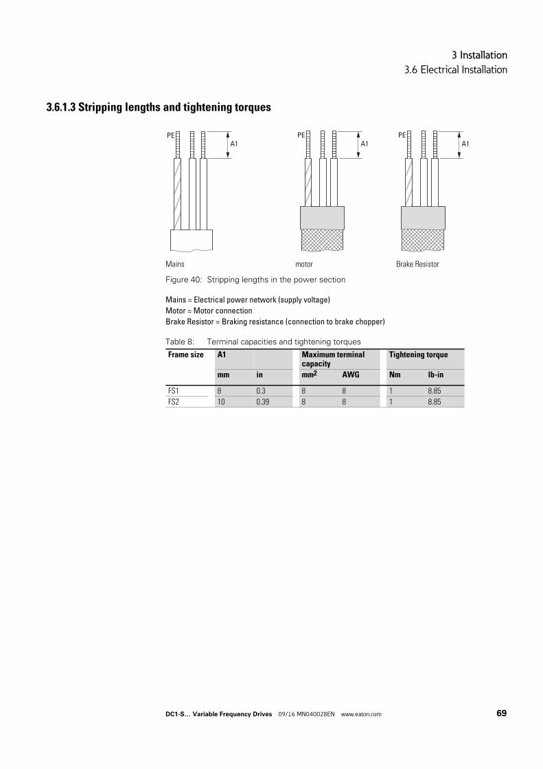
3 Installation
3.6 Electrical Installation
3.6.1.3 Stripping lengths and tightening torques
Figure 40: Stripping lengths in the power section
Mains = Electrical power network (supply voltage)
Motor = Motor connection
Brake Resistor = Braking resistance (connection to brake chopper)
Table 8: Terminal capacities and tightening torques
Mains motor Brake Resistor
PEA1
PEA1
PE A1
Frame size A1 Maximum terminal capacity
Tightening torque
mm in mm2 AWG Nm lb-in
FS1 8 0.3 8 8 1 8.85
FS2 10 0.39 8 8 1 8.85
DC1-S… Variable Frequency Drives 09/16 MN040028EN www.eaton.com 69
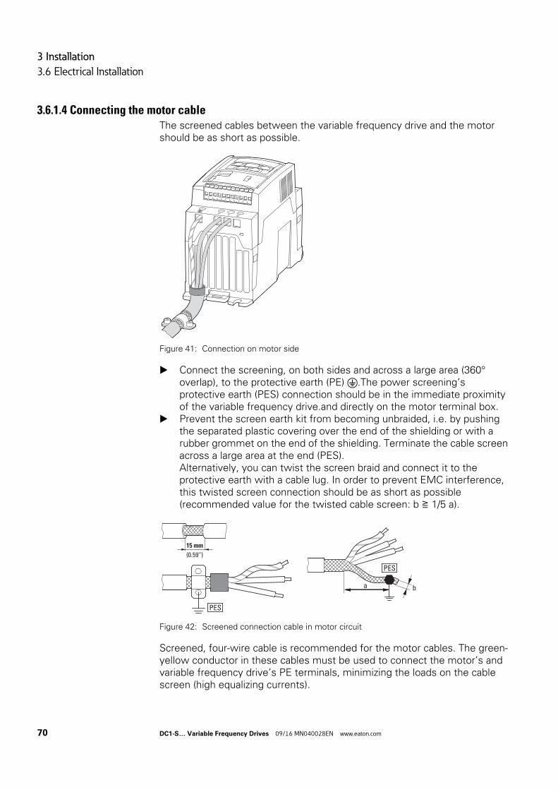
3 Installation
3.6 Electrical Installation
3.6.1.4 Connecting the motor cableThe screened cables between the variable frequency drive and the motor should be as short as possible.
Figure 41: Connection on motor side
Connect the screening, on both sides and across a large area (360° overlap), to the protective earth (PE) .The power screening’s protective earth (PES) connection should be in the immediate proximity of the variable frequency drive.and directly on the motor terminal box.
Prevent the screen earth kit from becoming unbraided, i.e. by pushing the separated plastic covering over the end of the shielding or with a rubber grommet on the end of the shielding. Terminate the cable screen across a large area at the end (PES).Alternatively, you can twist the screen braid and connect it to the protective earth with a cable lug. In order to prevent EMC interference, this twisted screen connection should be as short as possible (recommended value for the twisted cable screen: b ≧ 1/5 a).
Figure 42: Screened connection cable in motor circuit
Screened, four-wire cable is recommended for the motor cables. The green-yellow conductor in these cables must be used to connect the motor’s and variable frequency drive’s PE terminals, minimizing the loads on the cable screen (high equalizing currents).
15 mm
(0.59’’)
PES
a b
PES
70 DC1-S… Variable Frequency Drives 09/16 MN040028EN www.eaton.com
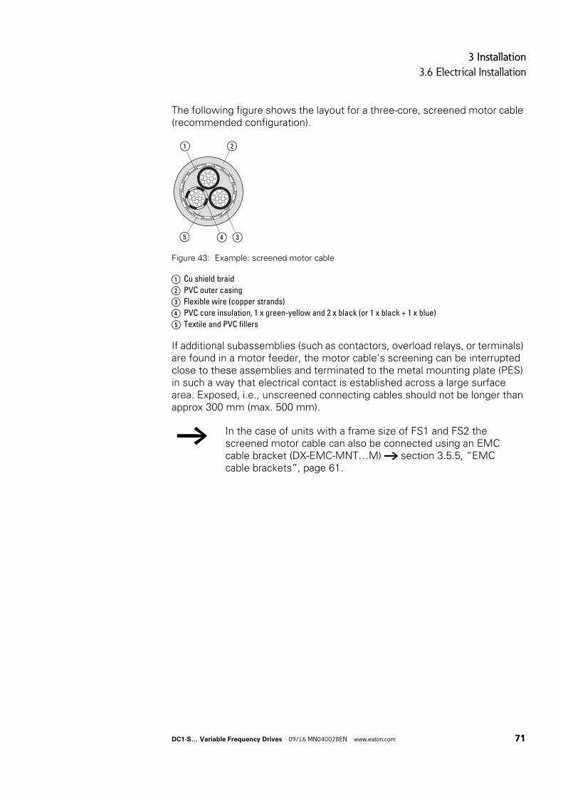
3 Installation
3.6 Electrical Installation
The following figure shows the layout for a three-core, screened motor cable (recommended configuration).
Figure 43: Example: screened motor cable
a Cu shield braid
b PVC outer casing
c Flexible wire (copper strands)
d PVC core insulation, 1 x green-yellow and 2 x black (or 1 x black + 1 x blue)
e Textile and PVC fillers
If additional subassemblies (such as contactors, overload relays, or terminals) are found in a motor feeder, the motor cable’s screening can be interrupted close to these assemblies and terminated to the metal mounting plate (PES) in such a way that electrical contact is established across a large surface area. Exposed, i.e., unscreened connecting cables should not be longer than approx 300 mm (max. 500 mm).
→ In the case of units with a frame size of FS1 and FS2 the screened motor cable can also be connected using an EMC cable bracket (DX-EMC-MNT…M) → section 3.5.5, “EMC cable brackets”, page 61.
②①
⑤ ③④
DC1-S… Variable Frequency Drives 09/16 MN040028EN www.eaton.com 71
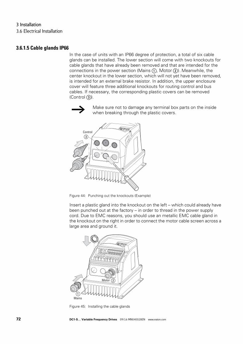
3 Installation
3.6 Electrical Installation
3.6.1.5 Cable glands IP66In the case of units with an IP66 degree of protection, a total of six cable glands can be installed. The lower section will come with two knockouts for cable glands that have already been removed and that are intended for the connections in the power section (Mains ①, Motor ②). Meanwhile, the center knockout in the lower section, which will not yet have been removed, is intended for an external brake resistor. In addition, the upper enclosure cover will feature three additional knockouts for routing control and bus cables. If necessary, the corresponding plastic covers can be removed (Control ③).
Figure 44: Punching out the knockouts (Example)
Insert a plastic gland into the knockout on the left – which could already have been punched out at the factory – in order to thread in the power supply cord. Due to EMC reasons, you should use an metallic EMC cable gland in the knockout on the right in order to connect the motor cable screen across a large area and ground it.
Figure 45: Installing the cable glands
→ Make sure not to damage any terminal box parts on the inside when breaking through the plastic covers.
③Control
L2NL3
UV W
L1N
1 2 3 4 5 6 7 8 9 10
1 2 3 4 5 6 7 8 9 10 11
Mains
Motor
①
②
72 DC1-S… Variable Frequency Drives 09/16 MN040028EN www.eaton.com
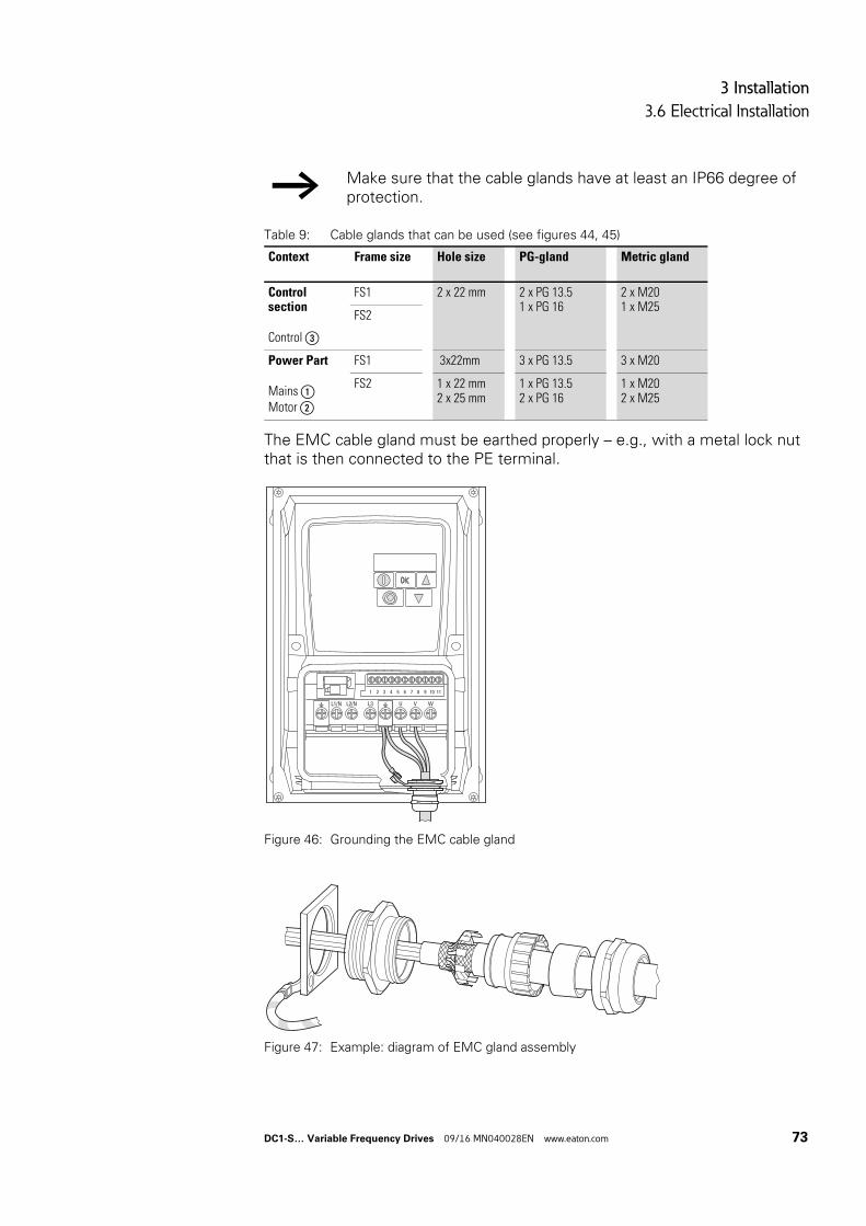
3 Installation
3.6 Electrical Installation
Table 9: Cable glands that can be used (see figures 44, 45)
The EMC cable gland must be earthed properly – e.g., with a metal lock nut that is then connected to the PE terminal.
Figure 46: Grounding the EMC cable gland
Figure 47: Example: diagram of EMC gland assembly
→ Make sure that the cable glands have at least an IP66 degree of protection.
Context Frame size Hole size PG-gland Metric gland
Control section
Control ③
FS1 2 x 22 mm 2 x PG 13.51 x PG 16
2 x M201 x M25
FS2
Power Part
Mains ①Motor ②
FS1 3x22mm 3 x PG 13.5 3 x M20
FS2 1 x 22 mm2 x 25 mm
1 x PG 13.52 x PG 16
1 x M202 x M25
1 2 3 4 5 6 7 8 9 10 11
U V WL1/N L2/N L3
DC1-S… Variable Frequency Drives 09/16 MN040028EN www.eaton.com 73
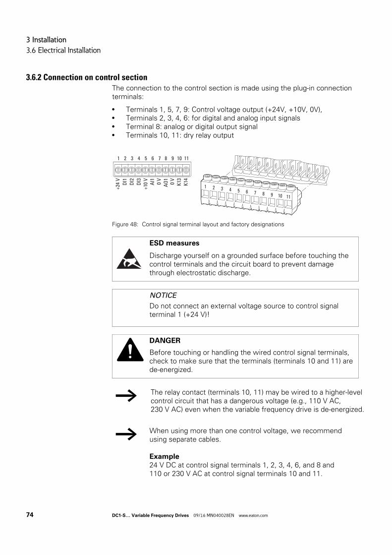
3 Installation
3.6 Electrical Installation
3.6.2 Connection on control sectionThe connection to the control section is made using the plug-in connection terminals:
• Terminals 1, 5, 7, 9: Control voltage output (+24V, +10V, 0V),• Terminals 2, 3, 4, 6: for digital and analog input signals• Terminal 8: analog or digital output signal• Terminals 10, 11: dry relay output
Figure 48: Control signal terminal layout and factory designations
ESD measures
Discharge yourself on a grounded surface before touching the control terminals and the circuit board to prevent damage through electrostatic discharge.
NOTICE
Do not connect an external voltage source to control signal terminal 1 (+24 V)!
DANGER
Before touching or handling the wired control signal terminals, check to make sure that the terminals (terminals 10 and 11) are de-energized.
→ The relay contact (terminals 10, 11) may be wired to a higher-level control circuit that has a dangerous voltage (e.g., 110 V AC, 230 V AC) even when the variable frequency drive is de-energized.
→ When using more than one control voltage, we recommend using separate cables.
Example24 V DC at control signal terminals 1, 2, 3, 4, 6, and 8 and110 or 230 V AC at control signal terminals 10 and 11.
1 2 3 4 5 6 7 8 9 10 11
+24
VD
I1
AI1 0 V
DI2
DI3
AO
10
VK
13K
14
+10
V
1 2 3 4 5 6 7 8 9 10 11
74 DC1-S… Variable Frequency Drives 09/16 MN040028EN www.eaton.com
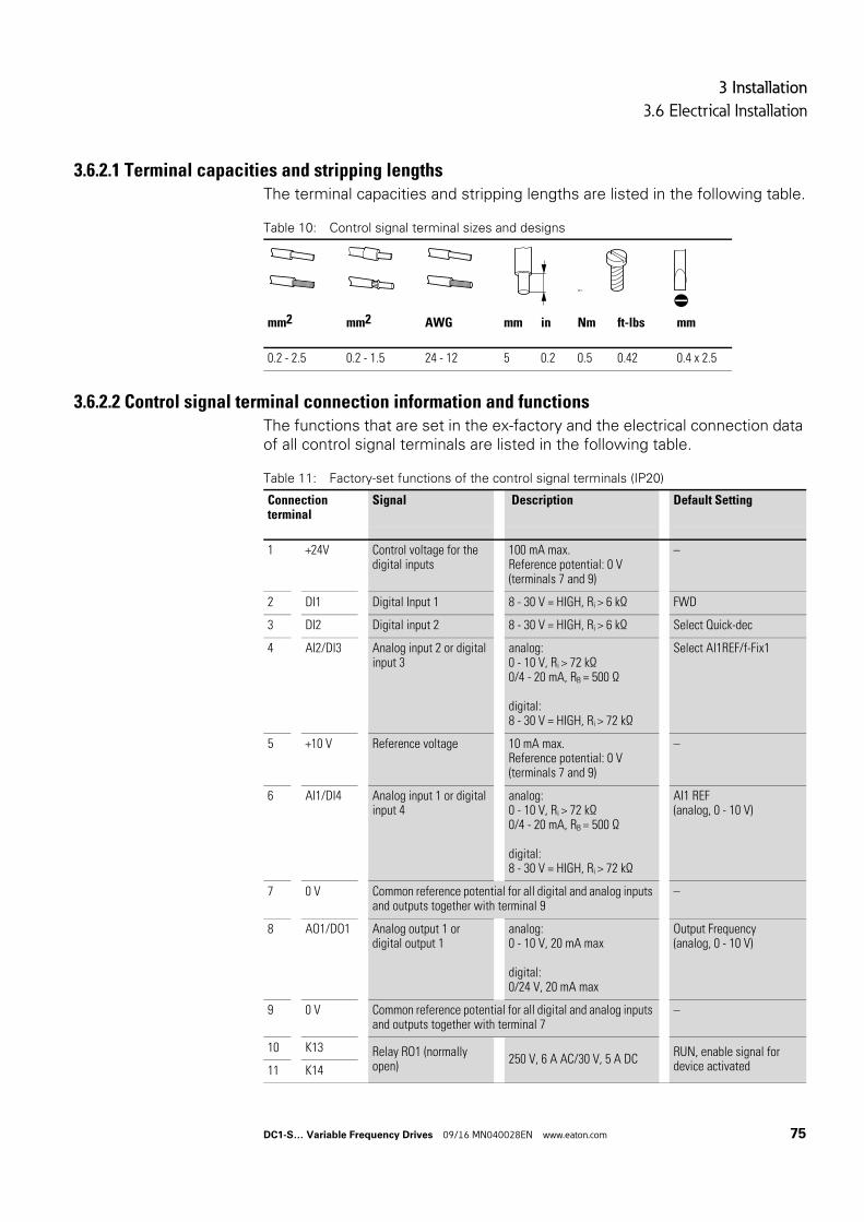
3 Installation
3.6 Electrical Installation
3.6.2.1 Terminal capacities and stripping lengthsThe terminal capacities and stripping lengths are listed in the following table.
Table 10: Control signal terminal sizes and designs
3.6.2.2 Control signal terminal connection information and functionsThe functions that are set in the ex-factory and the electrical connection data of all control signal terminals are listed in the following table.
Table 11: Factory-set functions of the control signal terminals (IP20)
M3
mm2 mm2 AWG mm in Nm ft-lbs mm
0.2 - 2.5 0.2 - 1.5 24 - 12 5 0.2 0.5 0.42 0.4 x 2.5
Connection terminal
Signal Description Default Setting
1 +24V Control voltage for the digital inputs
100 mA max.Reference potential: 0 V(terminals 7 and 9)
–
2 DI1 Digital Input 1 8 - 30 V = HIGH, Ri > 6 kΩ FWD
3 DI2 Digital input 2 8 - 30 V = HIGH, Ri > 6 kΩ Select Quick-dec
4 AI2/DI3 Analog input 2 or digital input 3
analog:0 - 10 V, Ri > 72 kΩ0/4 - 20 mA, RB = 500 Ω
digital:8 - 30 V = HIGH, Ri > 72 kΩ
Select AI1REF/f-Fix1
5 +10 V Reference voltage 10 mA max.Reference potential: 0 V(terminals 7 and 9)
–
6 AI1/DI4 Analog input 1 or digital input 4
analog:0 - 10 V, Ri > 72 kΩ0/4 - 20 mA, RB = 500 Ω
digital:8 - 30 V = HIGH, Ri > 72 kΩ
AI1 REF(analog, 0 - 10 V)
7 0 V Common reference potential for all digital and analog inputs and outputs together with terminal 9
–
8 AO1/DO1 Analog output 1 or digital output 1
analog:0 - 10 V, 20 mA max
digital:0/24 V, 20 mA max
Output Frequency(analog, 0 - 10 V)
9 0 V Common reference potential for all digital and analog inputs and outputs together with terminal 7
–
10 K13 Relay RO1 (normally open)
250 V, 6 A AC/30 V, 5 A DCRUN, enable signal for device activated11 K14
DC1-S… Variable Frequency Drives 09/16 MN040028EN www.eaton.com 75
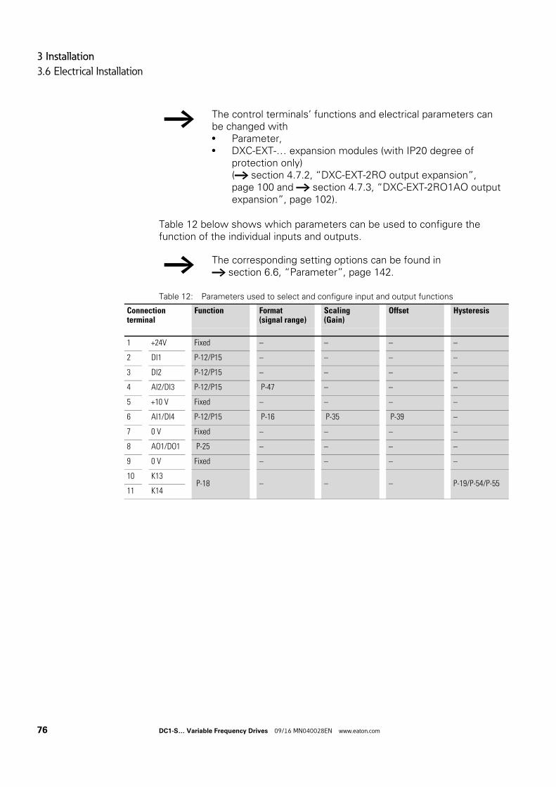
3 Installation
3.6 Electrical Installation
Table 12 below shows which parameters can be used to configure the function of the individual inputs and outputs.
Table 12: Parameters used to select and configure input and output functions
→ The control terminals’ functions and electrical parameters can be changed with• Parameter,• DXC-EXT-… expansion modules (with IP20 degree of
protection only)(→ section 4.7.2, “DXC-EXT-2RO output expansion”, page 100 and → section 4.7.3, “DXC-EXT-2RO1AO output expansion”, page 102).
→ The corresponding setting options can be found in → section 6.6, “Parameter”, page 142.
Connection terminal
Function Format(signal range)
Scaling(Gain)
Offset Hysteresis
1 +24V Fixed – – – –
2 DI1 P-12/P15 – – – –
3 DI2 P-12/P15 – – – –
4 AI2/DI3 P-12/P15 P-47 – – –
5 +10 V Fixed – – – –
6 AI1/DI4 P-12/P15 P-16 P-35 P-39 –
7 0 V Fixed – – – –
8 AO1/DO1 P-25 – – – –
9 0 V Fixed – – – –
10 K13 P-18 – – – P-19/P-54/P-55
11 K14
76 DC1-S… Variable Frequency Drives 09/16 MN040028EN www.eaton.com
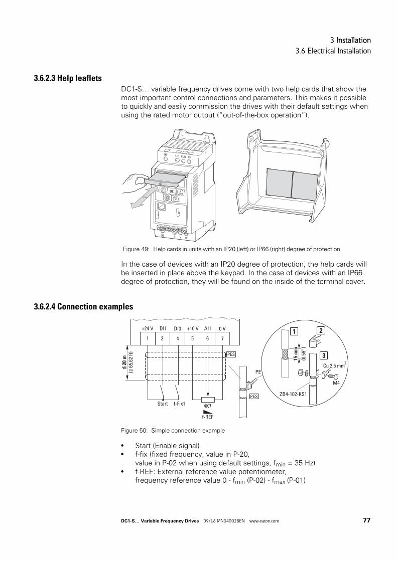
3 Installation
3.6 Electrical Installation
3.6.2.3 Help leafletsDC1-S… variable frequency drives come with two help cards that show the most important control connections and parameters. This makes it possible to quickly and easily commission the drives with their default settings when using the rated motor output (“out-of-the-box operation”).
In the case of devices with an IP20 degree of protection, the help cards will be inserted in place above the keypad. In the case of devices with an IP66 degree of protection, they will be found on the inside of the terminal cover.
3.6.2.4 Connection examples
Figure 50: Simple connection example
• Start (Enable signal)• f-fix (fixed frequency, value in P-20,
value in P-02 when using default settings, fmin = 35 Hz)• f-REF: External reference value potentiometer,
frequency reference value 0 - fmin (P-02) - fmax (P-01)
Figure 49: Help cards in units with an IP20 (left) or IP66 (right) degree of protection
L1/L L2/N L3
U V W
1 2 3 4 5 6 7 8 9 10 11
5 6 71 2 4
+10 V AI1 0 V+24 V DI1 DI3
PE
PES
PES
4K7
f-REF
ZB4-102-KS1
15 m
m
(0.5
9”)
M4
2Cu 2.5 mm
1 2
3
≦ 2
0 m
(≦ 6
5.62
ft)
f-Fix1Start
DC1-S… Variable Frequency Drives 09/16 MN040028EN www.eaton.com 77
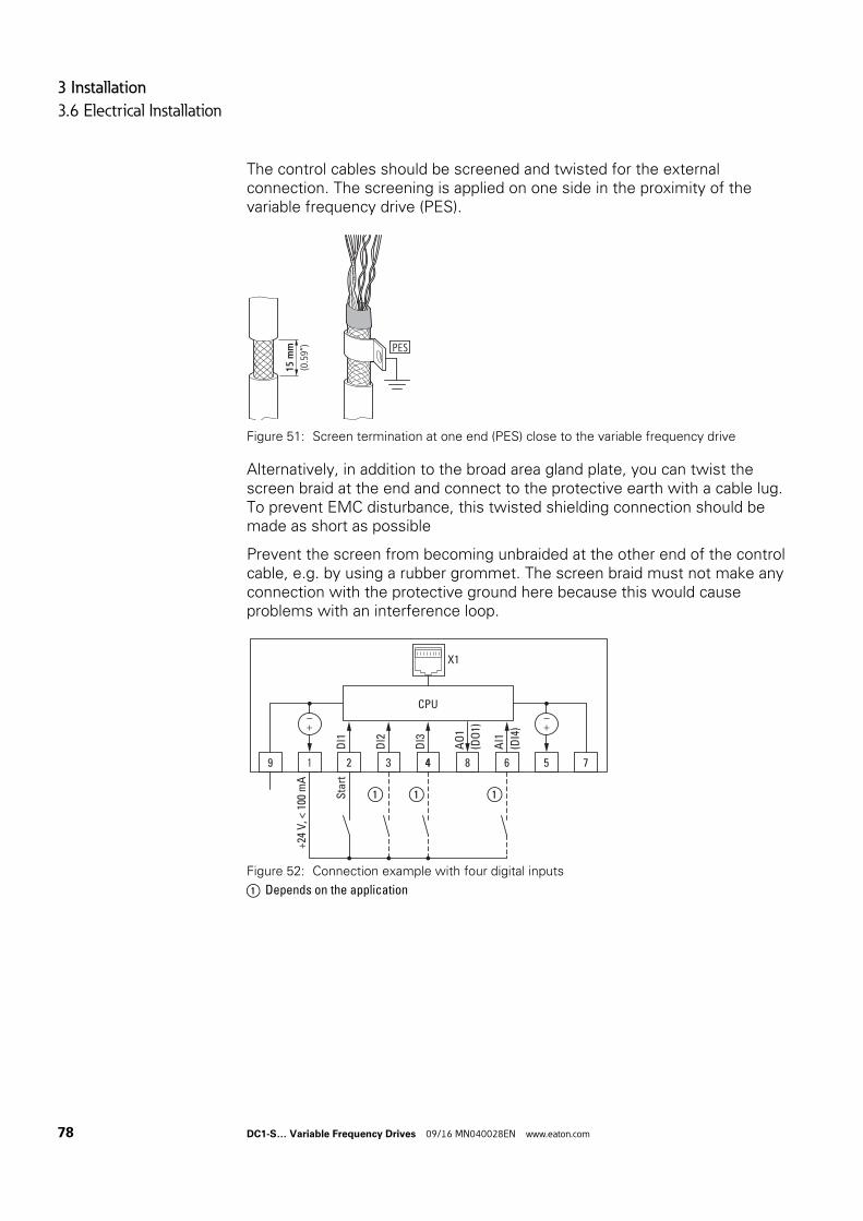
3 Installation
3.6 Electrical Installation
The control cables should be screened and twisted for the external connection. The screening is applied on one side in the proximity of the variable frequency drive (PES).
Figure 51: Screen termination at one end (PES) close to the variable frequency drive
Alternatively, in addition to the broad area gland plate, you can twist the screen braid at the end and connect to the protective earth with a cable lug. To prevent EMC disturbance, this twisted shielding connection should be made as short as possible
Prevent the screen from becoming unbraided at the other end of the control cable, e.g. by using a rubber grommet. The screen braid must not make any connection with the protective ground here because this would cause problems with an interference loop.
Figure 52: Connection example with four digital inputs
a Depends on the application
15 m
m(0.59’’) PES
Sta
rt
①
AI1
(DI4
)
DI2
DI3
DI1
64321
X1
+24
V, <
100
mA
AO
1
(DO
1)
759 8
CPU
4
① ①
78 DC1-S… Variable Frequency Drives 09/16 MN040028EN www.eaton.com
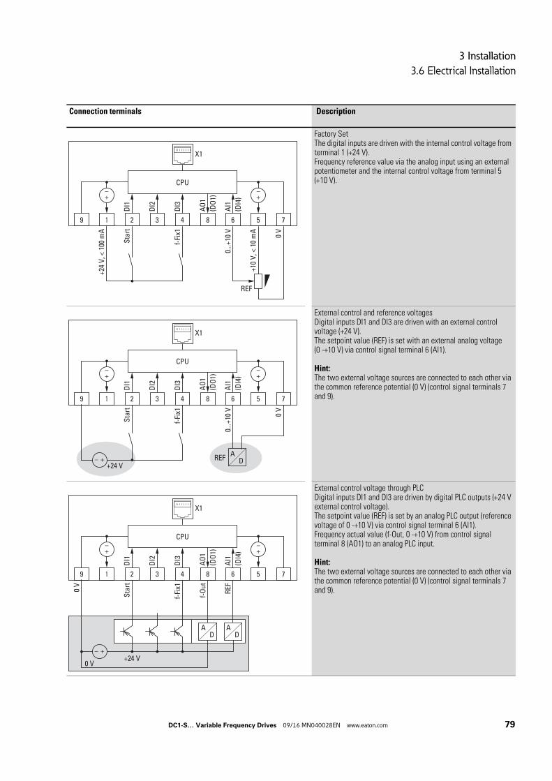
3 Installation
3.6 Electrical Installation
Connection terminals Description
Factory SetThe digital inputs are driven with the internal control voltage from terminal 1 (+24 V).Frequency reference value via the analog input using an external potentiometer and the internal control voltage from terminal 5 (+10 V).
External control and reference voltagesDigital inputs DI1 and DI3 are driven with an external control voltage (+24 V).The setpoint value (REF) is set with an external analog voltage(0 -+10 V) via control signal terminal 6 (AI1).
Hint:The two external voltage sources are connected to each other via the common reference potential (0 V) (control signal terminals 7 and 9).
External control voltage through PLCDigital inputs DI1 and DI3 are driven by digital PLC outputs (+24 V external control voltage).The setpoint value (REF) is set by an analog PLC output (reference voltage of 0 -+10 V) via control signal terminal 6 (AI1).Frequency actual value (f-Out, 0 -+10 V) from control signal terminal 8 (AO1) to an analog PLC input.
Hint:The two external voltage sources are connected to each other via the common reference potential (0 V) (control signal terminals 7 and 9).
0...+
10 V
Sta
rt
AI1
(DI4
)
DI2
f-Fi
x1D
I3
DI1
64321
X1
+10
V, <
10
mA
+24
V, <
100
mA
AO
1
(DO
1)
0 V
75
REF
9 8
CPU
0...+
10 V
Sta
rt
AI1
(DI4
)
DI2
f-Fi
x1D
I3
DI1
64321
X1
AO
1
(DO
1)
0 V
75
REF
9 8
CPU
AD
+24 V
REF
f-O
ut
Sta
rt
AI1
(DI4
)
DI2
f-Fi
x1D
I3
DI1
64321
X1
AO
1
(DO
1)
759 8
0 V
+24 V0 V
CPU
AD
AD
DC1-S… Variable Frequency Drives 09/16 MN040028EN www.eaton.com 79
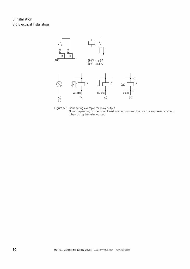
3 Installation
3.6 Electrical Installation
Figure 53: Connecting example for relay outputNote: Depending on the type of load, we recommend the use of a suppressor circuit when using the relay output.
250 V ∼ : ≦ 6 A30 V : ≦ 5 A
10
RUN
11
K13
K14
K1
I
ACDC
AC
Varistor(+)
(-)
DC
Diode
AC
RC filter
80 DC1-S… Variable Frequency Drives 09/16 MN040028EN www.eaton.com
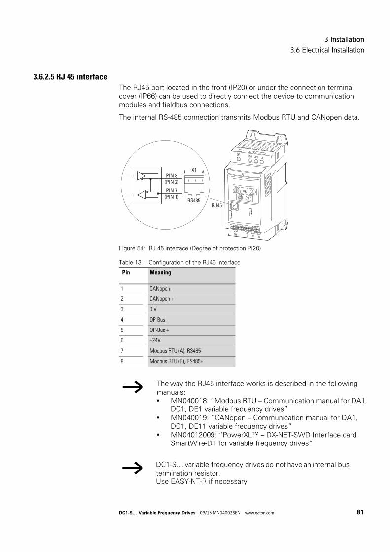
3 Installation
3.6 Electrical Installation
3.6.2.5 RJ 45 interfaceThe RJ45 port located in the front (IP20) or under the connection terminal cover (IP66) can be used to directly connect the device to communication modules and fieldbus connections.
The internal RS-485 connection transmits Modbus RTU and CANopen data.
Figure 54: RJ 45 interface (Degree of protection PI20)
Table 13: Configuration of the RJ45 interface
Pin Meaning
1 CANopen -
2 CANopen +
3 0 V
4 OP-Bus -
5 OP-Bus +
6 +24V
7 Modbus RTU (A), RS485-
8 Modbus RTU (B), RS485+
→ The way the RJ45 interface works is described in the following manuals:• MN040018: “Modbus RTU – Communication manual for DA1,
DC1, DE1 variable frequency drives”• MN040019: “CANopen – Communication manual for DA1,
DC1, DE11 variable frequency drives”• MN04012009: “PowerXL™ – DX-NET-SWD Interface card
SmartWire-DT for variable frequency drives”
→ DC1-S… variable frequency drives do not have an internal bus termination resistor.Use EASY-NT-R if necessary.
L1/L L2/N L3
U V W
1 2 3 4 5 6 7 8 9 10 11
PIN 8(PIN 2)
PIN 7(PIN 1)
RS485RJ45
X11 8
DC1-S… Variable Frequency Drives 09/16 MN040028EN www.eaton.com 81
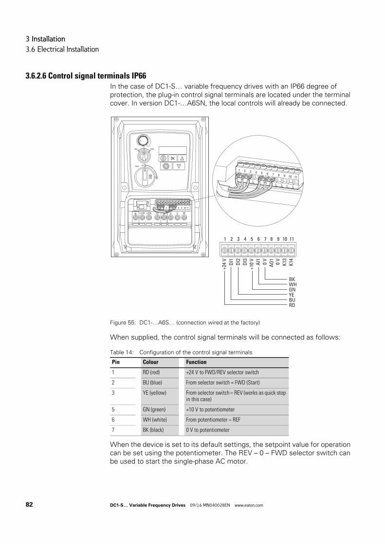
3 Installation
3.6 Electrical Installation
3.6.2.6 Control signal terminals IP66In the case of DC1-S… variable frequency drives with an IP66 degree of protection, the plug-in control signal terminals are located under the terminal cover. In version DC1-…A6SN, the local controls will already be connected.
Figure 55: DC1-…A6S… (connection wired at the factory)
When supplied, the control signal terminals will be connected as follows:
Table 14: Configuration of the control signal terminals
When the device is set to its default settings, the setpoint value for operation can be set using the potentiometer. The REV – 0 – FWD selector switch can be used to start the single-phase AC motor.
Pin Colour Function
1 RD (red) +24 V to FWD/REV selector switch
2 BU (blue) From selector switch = FWD (Start)
3 YE (yellow) From selector switch = REV (works as quick stop in this case)
5 GN (green) +10 V to potentiometer
6 WH (white) From potentiometer = REF
7 BK (black) 0 V to potentiometer
REV FWD0
ON
OFFPWR
1 2 3 4 5 6 7 8 9 10 11
U V WL1/N L2/N L3
1 2 3 4 5 6 7 8 9 10 11
1 2 3 4 5 6 7 8 9 10 11
+24
VD
I1
AI1 0 V
DI2
DI3
AO
10
VK
13K
14
+10
V
BKWHGNYEBURD
82 DC1-S… Variable Frequency Drives 09/16 MN040028EN www.eaton.com
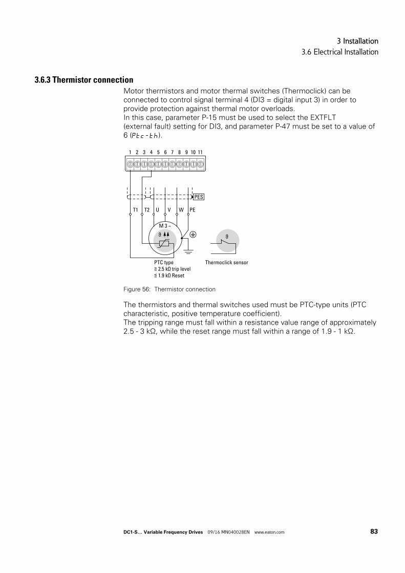
3 Installation
3.6 Electrical Installation
3.6.3 Thermistor connectionMotor thermistors and motor thermal switches (Thermoclick) can be connected to control signal terminal 4 (DI3 = digital input 3) in order to provide protection against thermal motor overloads.In this case, parameter P-15 must be used to select the EXTFLT (external fault) setting for DI3, and parameter P-47 must be set to a value of 6 (Ptc-th).
Figure 56: Thermistor connection
The thermistors and thermal switches used must be PTC-type units (PTC characteristic, positive temperature coefficient).The tripping range must fall within a resistance value range of approximately 2.5 - 3 kΩ, while the reset range must fall within a range of 1.9 - 1 kΩ.
T1 T2
M 3 ∼
Thermoclick sensor
ϑ ϑ
U V W PE
PTC type≧ 2.5 kΩ trip level≦ 1.9 kΩ Reset
PES
1 2 3 4 5 6 7 8 9 10 11
DC1-S… Variable Frequency Drives 09/16 MN040028EN www.eaton.com 83

3 Installation
3.7 Block diagrams
3.7 Block diagrams
The following block diagrams show all the connection terminals on a DC1-S variable frequency drive and their functions when in their default settings.
84 DC1-S… Variable Frequency Drives 09/16 MN040028EN www.eaton.com
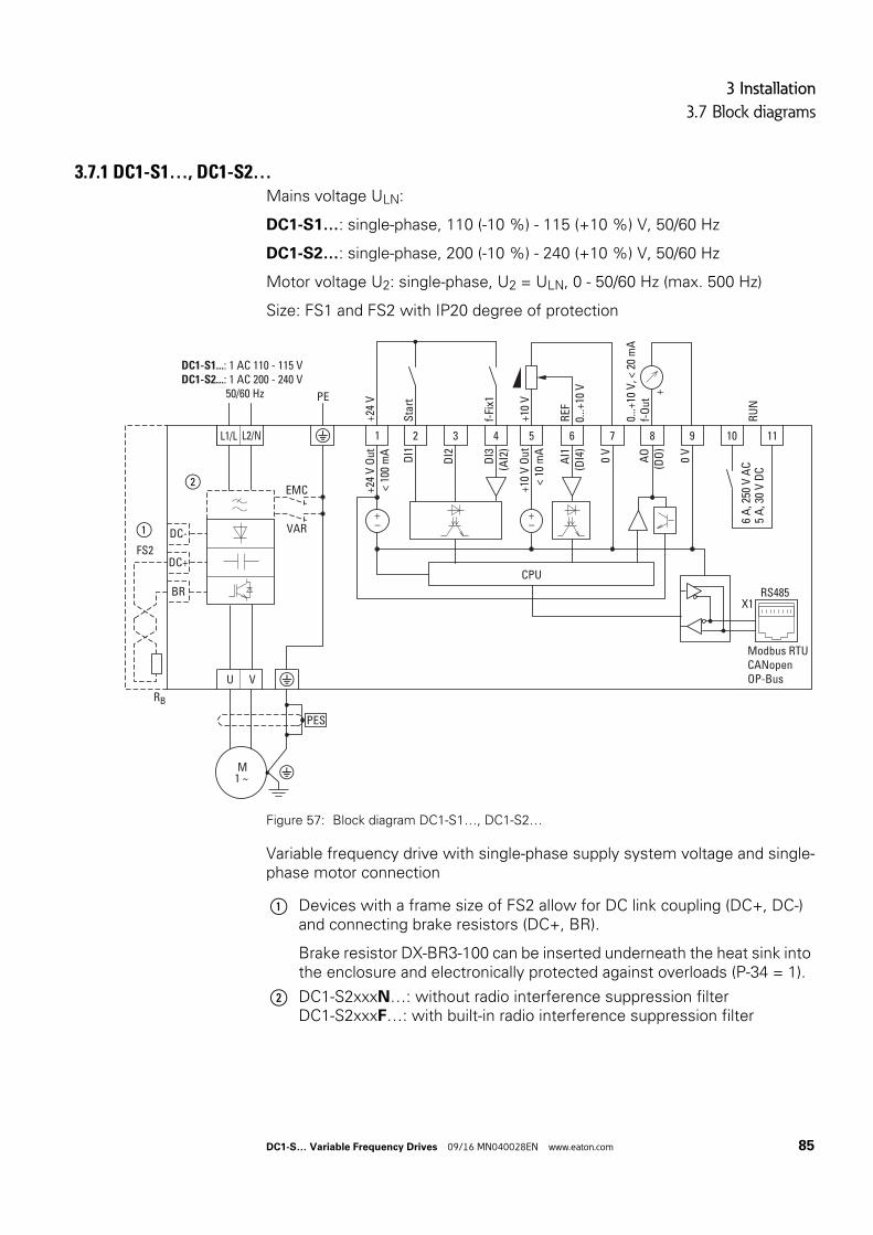
3 Installation
3.7 Block diagrams
3.7.1 DC1-S1…, DC1-S2…Mains voltage ULN:
DC1-S1…: single-phase, 110 (-10 %) - 115 (+10 %) V, 50/60 Hz
DC1-S2…: single-phase, 200 (-10 %) - 240 (+10 %) V, 50/60 Hz
Motor voltage U2: single-phase, U2 = ULN, 0 - 50/60 Hz (max. 500 Hz)
Size: FS1 and FS2 with IP20 degree of protection
Figure 57: Block diagram DC1-S1…, DC1-S2…
Variable frequency drive with single-phase supply system voltage and single-phase motor connection
DC+
BR
DC-
VU
M1 ~
L1/L
EMC
L2/N
VAR
DC1-S1...: 1 AC 110 - 115 VDC1-S2...: 1 AC 200 - 240 V 50/60 Hz
PES
2
DI1
Sta
rt
+24
V
3D
I24
DI3
(AI2
)f-
Fix1
5
+10
V O
ut<
10 m
A+1
0 V
6
AI1
(DI4
)R
EF
7
0 V
1
+24
V O
ut<
100
mA
8
AO
(DO
)
0...+
10 V
, < 2
0 m
Af-
Out
+
9
0 V
10 11
RU
N6
A, 2
50 V
AC
5 A
, 30
V D
C
RS485
CPU0.
..+10
V
Modbus RTUCANopenOP-Bus
X1
①
FS2
②
RB
PE
① Devices with a frame size of FS2 allow for DC link coupling (DC+, DC-) and connecting brake resistors (DC+, BR).
Brake resistor DX-BR3-100 can be inserted underneath the heat sink into the enclosure and electronically protected against overloads (P-34 = 1).
② DC1-S2xxxN…: without radio interference suppression filterDC1-S2xxxF…: with built-in radio interference suppression filter
DC1-S… Variable Frequency Drives 09/16 MN040028EN www.eaton.com 85
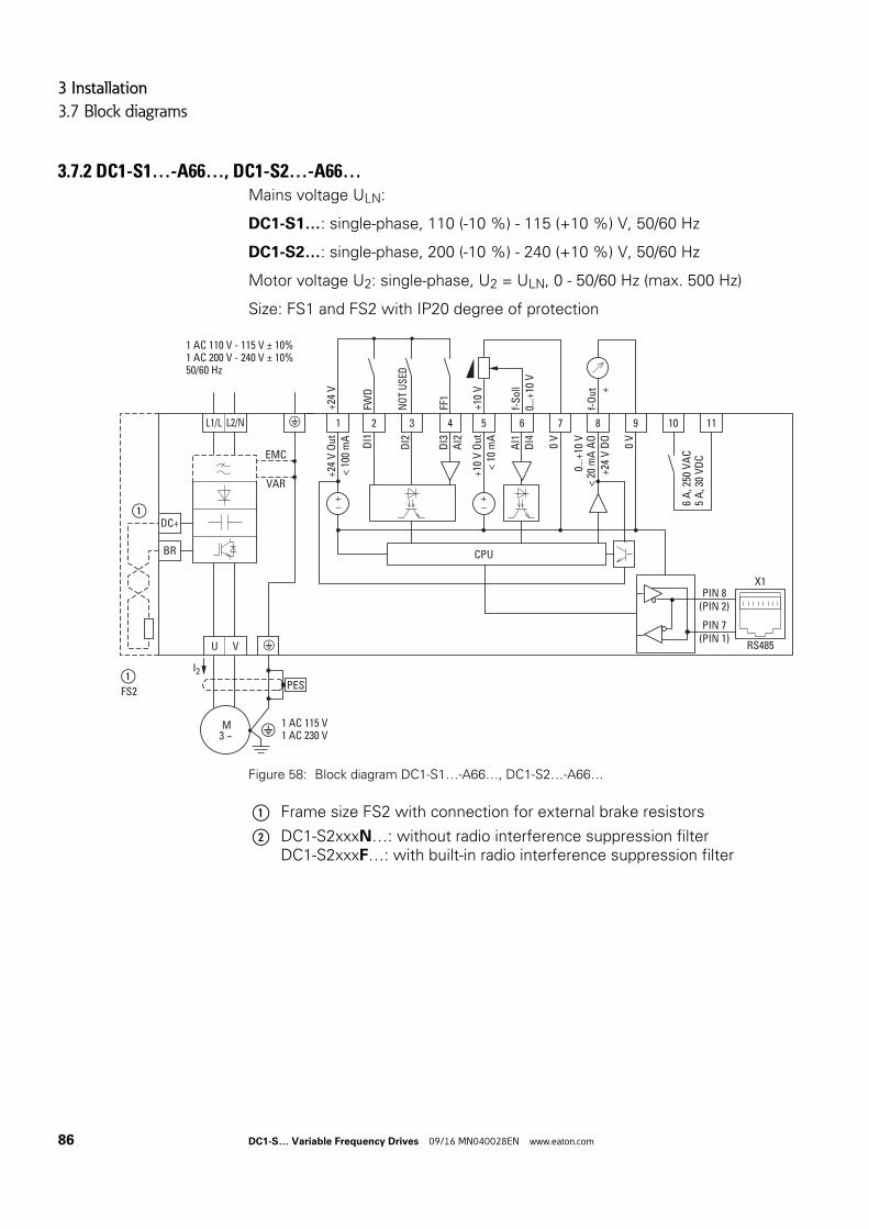
3 Installation
3.7 Block diagrams
3.7.2 DC1-S1…-A66…, DC1-S2…-A66…Mains voltage ULN:
DC1-S1…: single-phase, 110 (-10 %) - 115 (+10 %) V, 50/60 Hz
DC1-S2…: single-phase, 200 (-10 %) - 240 (+10 %) V, 50/60 Hz
Motor voltage U2: single-phase, U2 = ULN, 0 - 50/60 Hz (max. 500 Hz)
Size: FS1 and FS2 with IP20 degree of protection
Figure 58: Block diagram DC1-S1…-A66…, DC1-S2…-A66…
2
DI1
3
DI2
4
DI3
AI2
5
+10
V O
ut<
10 m
A
6
AI1
DI4
7
0 V
1
+24
V O
ut<
100
mA
8
0...+
10 V
< 20
mA
AO
+24
V D
O
9
0 V
10 11
6 A
, 250
VA
C5
A, 3
0 V
DC
CPU
PIN 8(PIN 2)
PIN 7(PIN 1)
RS485
X1
FWD
+24
V
NO
T U
SED
FF1
+10
V
f-S
oll
f-O
ut +
0...+
10 V
DC+
BR
1 AC 115 V1 AC 230 V
EMC
VAR
PES
①
VU
① FS2
M3 ~
L1/L L2/N
1 AC 110 V - 115 V ± 10%1 AC 200 V - 240 V ± 10%50/60 Hz
I2
① Frame size FS2 with connection for external brake resistors
② DC1-S2xxxN…: without radio interference suppression filterDC1-S2xxxF…: with built-in radio interference suppression filter
86 DC1-S… Variable Frequency Drives 09/16 MN040028EN www.eaton.com
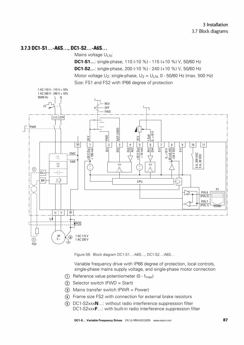
3 Installation
3.7 Block diagrams
3.7.3 DC1-S1…-A6S…, DC1-S2…-A6S…Mains voltage ULN:
DC1-S1…: single-phase, 110 (-10 %) - 115 (+10 %) V, 50/60 Hz
DC1-S2…: single-phase, 200 (-10 %) - 240 (+10 %) V, 50/60 Hz
Motor voltage U2: single-phase, U2 = ULN, 0 - 50/60 Hz (max. 500 Hz)
Size: FS1 and FS2 with IP66 degree of protection
Figure 59: Block diagram DC1-S1…-A6S…, DC1-S2…-A6S…
Variable frequency drive with IP66 degree of protection, local controls, single-phase mains supply voltage, and single-phase motor connection
2
DI1
24 V
3
DI2
NO
T U
SED
FWD
4
DI3
AI2
5
+10
V O
ut<
10 m
A10
V
6A
I1D
I4f-
Sol
l7
0 V
1
+24
V O
ut<
100
mA
REVOFFFWD
8
0...+
10 V
< 20
mA
AO
+24
V D
O
9
0 V
10 11
6 A
, 250
VA
C5
A, 3
0 V
DC
CPU
0...+
10 V
PIN 8(PIN 2)
PIN 7(PIN 1) RS485
X1
DC+
BR
1 AC 115 V1 AC 230 V
EMC
VAR
PES
①
VU
M3 ~
L1/L L2/N
I2
1 AC 110 V - 115 V ± 10%1 AC 200 V - 240 V ± 10%50/60 Hz L
F1
N
PWR
① FS2
① Reference value potentiometer (0 - fmax)
② Selector switch (FWD = Start)
③ Mains transfer switch (PWR = Power)
④ Frame size FS2 with connection for external brake resistors
⑤ DC1-S2xxxN…: without radio interference suppression filterDC1-S2xxxF…: with built-in radio interference suppression filter
DC1-S… Variable Frequency Drives 09/16 MN040028EN www.eaton.com 87

3 Installation
3.7 Block diagrams
88 DC1-S… Variable Frequency Drives 09/16 MN040028EN www.eaton.com
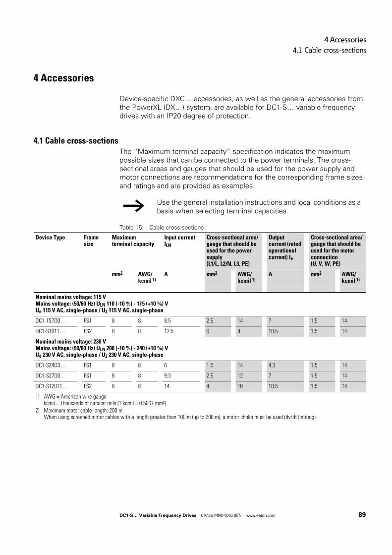
4 Accessories
4.1 Cable cross-sections
4 Accessories
Device-specific DXC… accessories, as well as the general accessories from the PowerXL (DX…) system, are available for DC1-S… variable frequency drives with an IP20 degree of protection.
4.1 Cable cross-sectionsThe “Maximum terminal capacity” specification indicates the maximum possible sizes that can be connected to the power terminals. The cross-sectional areas and gauges that should be used for the power supply and motor connections are recommendations for the corresponding frame sizes and ratings and are provided as examples.
Table 15: Cable cross-sections
→ Use the general installation instructions and local conditions as a basis when selecting terminal capacities.
Device Type Frame size
Maximum terminal capacity
Input current ILN
Cross-sectional area/gauge that should be used for the power supply(L1/L, L2/N, L3, PE)
Output current (rated operational current) Ie
Cross-sectional area/gauge that should be used for the motor connection(U, V, W, PE)
mm2 AWG/kcmil 1)
A mm2 AWG/kcmil 1)
A mm2 AWG/kcmil 1)
Nominal mains voltage: 115 VMains voltage: (50/60 Hz) ULN 110 (-10 %) - 115 (+10 %) VUe 115 V AC, single-phase / U2 115 V AC, single-phase
DC1-1S7D0… FS1 8 8 8.5 2.5 14 7 1.5 14
DC1-S1011… FS2 8 8 12.5 6 8 10.5 1.5 14
Nominal mains voltage: 230 VMains voltage: (50/60 Hz) ULN 200 (-10 %) - 240 (+10 %) VUe 230 V AC, single-phase / U2 230 V AC, single-phase
DC1-S24D3… FS1 8 8 6 1.5 14 4.3 1.5 14
DC1-S27D0… FS1 8 8 9.3 2.5 12 7 1.5 14
DC1-S12011… FS2 8 8 14 4 10 10.5 1.5 14
1) AWG = American wire gaugekcmil = Thousands of circular mils (1 kcmil = 0.5067 mm²)
2) Maximum motor cable length: 200 mWhen using screened motor cables with a length greater than 100 m (up to 200 m), a motor choke must be used (dv/dt limiting).
DC1-S… Variable Frequency Drives 09/16 MN040028EN www.eaton.com 89
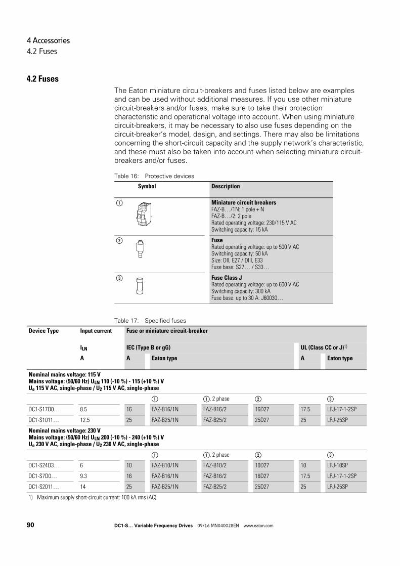
4 Accessories
4.2 Fuses
4.2 Fuses
The Eaton miniature circuit-breakers and fuses listed below are examples and can be used without additional measures. If you use other miniature circuit-breakers and/or fuses, make sure to take their protection characteristic and operational voltage into account. When using miniature circuit-breakers, it may be necessary to also use fuses depending on the circuit-breaker’s model, design, and settings. There may also be limitations concerning the short-circuit capacity and the supply network’s characteristic, and these must also be taken into account when selecting miniature circuit-breakers and/or fuses.
Table 16: Protective devices
Table 17: Specified fuses
Symbol Description
① Miniature circuit breakersFAZ-B…/1N: 1 pole + NFAZ-B…/2: 2 poleRated operating voltage: 230/115 V ACSwitching capacity: 15 kA
② FuseRated operating voltage: up to 500 V ACSwitching capacity: 50 kASize: DII, E27 / DIII, E33Fuse base: S27… / S33…
③ Fuse Class JRated operating voltage: up to 600 V ACSwitching capacity: 300 kAFuse base: up to 30 A: J60030…
Device Type Input current Fuse or miniature circuit-breaker
ILN IEC (Type B or gG) UL (Class CC or J)1)
A A Eaton type A Eaton type
Nominal mains voltage: 115 VMains voltage: (50/60 Hz) ULN 110 (-10 %) - 115 (+10 %) VUe 115 V AC, single-phase / U2 115 V AC, single-phase
① ①, 2 phase ② ③
DC1-S17D0… 8.5 16 FAZ-B16/1N FAZ-B16/2 16D27 17.5 LPJ-17-1-2SP
DC1-S1011… 12.5 25 FAZ-B25/1N FAZ-B25/2 25D27 25 LPJ-25SP
Nominal mains voltage: 230 VMains voltage: (50/60 Hz) ULN 200 (-10 %) - 240 (+10 %) VUe 230 V AC, single-phase / U2 230 V AC, single-phase
① ①, 2 phase ② ③
DC1-S24D3… 6 10 FAZ-B10/1N FAZ-B10/2 10D27 10 LPJ-10SP
DC1-S7D0… 9.3 16 FAZ-B16/1N FAZ-B16/2 16D27 17.5 LPJ-17-1-2SP
DC1-S2011… 14 25 FAZ-B25/1N FAZ-B25/2 25D27 25 LPJ-25SP
1) Maximum supply short-circuit current: 100 kA rms (AC)
90 DC1-S… Variable Frequency Drives 09/16 MN040028EN www.eaton.com
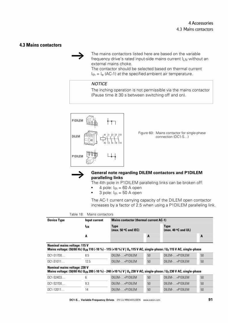
4 Accessories
4.3 Mains contactors
4.3 Mains contactors
Table 18: Mains contactors
→ The mains contactors listed here are based on the variable frequency drive’s rated input-side mains current ILN without an external mains choke.The contactor should be selected based on thermal current Ith = Ie (AC-1) at the specified ambient air temperature.
NOTICE
The inching operation is not permissible via the mains contactor (Pause time ≧ 30 s between switching off and on).
Figure 60: Mains contactor for single-phase connection (DC1-S…)
→ General note regarding DILEM contactors and P1DILEM paralleling linksThe 4th pole in P1DILEM paralleling links can be broken off:• 4 pole: Ith = 60 A open• 3 pole: Ith = 50 A open
The AC-1 current carrying capacity of the DILEM open contactor increases by a factor of 2.5 when using a P1DILEM paralleling link.
P1DILEM
DILEM
P1DILEM
2
3 5
4 6
A1
A2
1 13
14
Device Type Input current Mains contactor (thermal current AC-1)
ILN Type(max. 50 oC and IEC)
Type(max. 40 oC and UL)
A A A
Nominal mains voltage: 115 VMains voltage: (50/60 Hz) ULN 110 (-10 %) - 115 (+10 %) V | Ue 115 V AC, single-phase / U2 115 V AC, single-phase
DC1-S17D0… 8.5 DILEM-…+P1DILEM 50 DILEM-…+P1DILEM 50
DC1-S1011… 12.5 DILEM-…+P1DILEM 50 DILEM-…+P1DILEM 50
Nominal mains voltage: 230 VMains voltage: (50/60 Hz) ULN 200 (-10 %) - 240 (+10 %) V | Ue 230 V AC, single-phase / U2 230 V AC, single-phase
DC1-S24D3… 6 DILEM-…+P1DILEM 50 DILEM-…+P1DILEM 50
DC1-S27D0… 9.3 DILEM-…+P1DILEM 50 DILEM-…+P1DILEM 50
DC1-12011… 14 DILEM-…+P1DILEM 50 DILEM-…+P1DILEM 50
DC1-S… Variable Frequency Drives 09/16 MN040028EN www.eaton.com 91
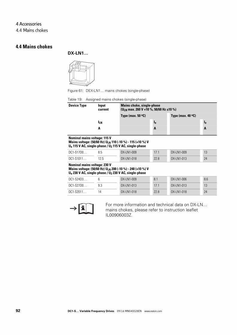
4 Accessories
4.4 Mains chokes
4.4 Mains chokesDX-LN1…
Figure 61: DEX-LN1… mains chokes (single-phase)
Table 19: Assigned mains chokes (single-phase)
Device Type Input current
Mains choke, single-phase(ULN max. 260 V +10 %, 50/60 Hz ±10 %)
Type (max. 50 oC) Type (max. 40 oC)
ILN Ie Ie
A A A
Nominal mains voltage: 115 VMains voltage: (50/60 Hz) ULN 110 (-10 %) - 115 (+10 %) VUe 115 V AC, single-phase / U2 115 V AC, single-phase
DC1-S17D0… 8.5 DX-LN1-009 17.1 DX-LN1-009 13
DC1-S1011… 12.5 DX-LN1-018 22.8 DX-LN1-013 24
Nominal mains voltage: 230 VMains voltage: (50/60 Hz) ULN 200 (-10 %) - 240 (+10 %) VUe 230 V AC, single-phase / U2 230 V AC, single-phase
DC1-S24D3… 6 DX-LN1-009 8.1 DX-LN1-006 8.6
DC1-S27D0… 9.3 DX-LN1-013 17.1 DX-LN1-013 13
DC1-S2011… 14 DX-LN1-018 22.8 DX-LN1-018 24
For more information and technical data on DX-LN… mains chokes, please refer to instruction leaflet IL00906003Z.
a
92 DC1-S… Variable Frequency Drives 09/16 MN040028EN www.eaton.com
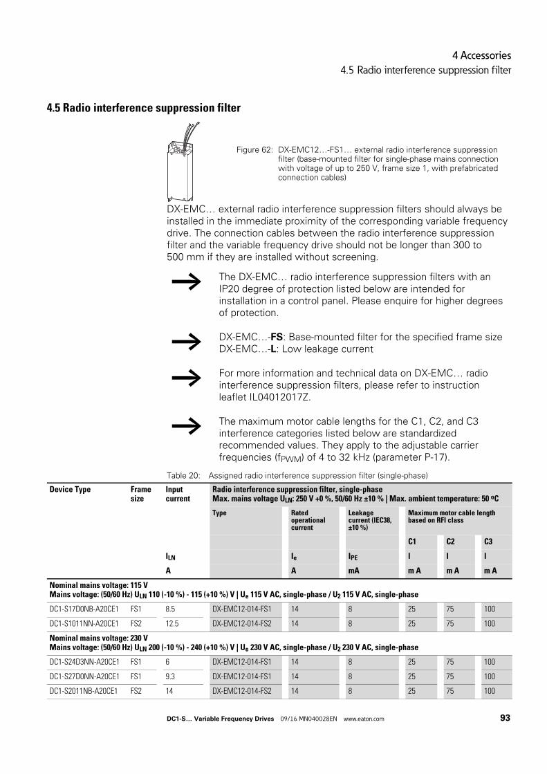
4 Accessories
4.5 Radio interference suppression filter
4.5 Radio interference suppression filter
DX-EMC… external radio interference suppression filters should always be installed in the immediate proximity of the corresponding variable frequency drive. The connection cables between the radio interference suppression filter and the variable frequency drive should not be longer than 300 to 500 mm if they are installed without screening.
Table 20: Assigned radio interference suppression filter (single-phase)
Figure 62: DX-EMC12…-FS1… external radio interference suppression filter (base-mounted filter for single-phase mains connection with voltage of up to 250 V, frame size 1, with prefabricated connection cables)
→ The DX-EMC… radio interference suppression filters with an IP20 degree of protection listed below are intended for installation in a control panel. Please enquire for higher degrees of protection.
→ DX-EMC…-FS: Base-mounted filter for the specified frame sizeDX-EMC…-L: Low leakage current
→ For more information and technical data on DX-EMC… radio interference suppression filters, please refer to instruction leaflet IL04012017Z.
→ The maximum motor cable lengths for the C1, C2, and C3 interference categories listed below are standardized recommended values. They apply to the adjustable carrier frequencies (fPWM) of 4 to 32 kHz (parameter P-17).
Device Type Frame size
Input current
Radio interference suppression filter, single-phaseMax. mains voltage ULN: 250 V +0 %, 50/60 Hz ±10 % | Max. ambient temperature: 50 oC
Type Rated operational current
Leakage current (IEC38, ±10 %)
Maximum motor cable length based on RFI class
C1 C2 C3
ILN Ie IPE l l l
A A mA m A m A m A
Nominal mains voltage: 115 VMains voltage: (50/60 Hz) ULN 110 (-10 %) - 115 (+10 %) V | Ue 115 V AC, single-phase / U2 115 V AC, single-phase
DC1-S17D0NB-A20CE1 FS1 8.5 DX-EMC12-014-FS1 14 8 25 75 100
DC1-S1011NN-A20CE1 FS2 12.5 DX-EMC12-014-FS2 14 8 25 75 100
Nominal mains voltage: 230 VMains voltage: (50/60 Hz) ULN 200 (-10 %) - 240 (+10 %) V | Ue 230 V AC, single-phase / U2 230 V AC, single-phase
DC1-S24D3NN-A20CE1 FS1 6 DX-EMC12-014-FS1 14 8 25 75 100
DC1-S27D0NN-A20CE1 FS1 9.3 DX-EMC12-014-FS1 14 8 25 75 100
DC1-S2011NB-A20CE1 FS2 14 DX-EMC12-014-FS2 14 8 25 75 100
DC1-S… Variable Frequency Drives 09/16 MN040028EN www.eaton.com 93
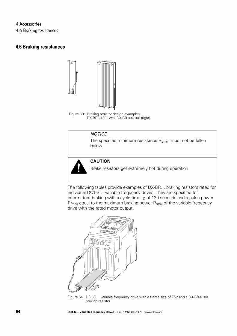
4 Accessories
4.6 Braking resistances
4.6 Braking resistances
The following tables provide examples of DX-BR… braking resistors rated for individual DC1-S… variable frequency drives. They are specified for intermittent braking with a cycle time tC of 120 seconds and a pulse power PPeak equal to the maximum braking power Pmax of the variable frequency drive with the rated motor output.
Figure 64: DC1-S… variable frequency drive with a frame size of FS2 and a DX-BR3-100 braking resistor
Figure 63: Braking resistor design examples:DX-BR3-100 (left), DX-BR100-100 (right)
NOTICE
The specified minimum resistance RBmin must not be fallen below.
CAUTION
Brake resistors get extremely hot during operation!
94 DC1-S… Variable Frequency Drives 09/16 MN040028EN www.eaton.com
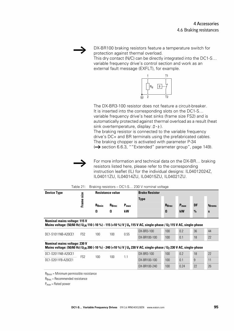
4 Accessories
4.6 Braking resistances
Table 21: Braking resistors – DC1-S… 230 V nominal voltage
→ DX-BR100 braking resistors feature a temperature switch for protection against thermal overload.This dry contact (N/C) can be directly integrated into the DC1-S… variable frequency drive’s control section and work as an external fault message (EXFLT), for example.
The DX-BR3-100 resistor does not feature a circuit-breaker.It is inserted into the corresponding slots on the DC1-S… variable frequency drive’s heat sinks (frame size FS2) and is automatically protected against thermal overload as a result (heat sink overtemperature, display: O-t).The braking resistor is connected to the variable frequency drive’s DC+ and BR terminals using the prefabricated cables.The braking chopper is activated with parameter P-34 (→ section 6.6.3, ““Extended” parameter group”, page 149).
→ For more information and technical data on the DX-BR… braking resistors listed here, please refer to the corresponding instruction leaflet (IL) for the individual designs: IL04012024Z, IL04011ZU, IL04014ZU, IL04015ZU, IL04021ZU.
ϑRB
2 T2
1 T1
Device Type
Fram
e si
ze Resistance value Brake Resistor
Type
RBmin RBrec Pmax RBrec Pmax DF tBrems
Ω Ω kW Ω kW % s
Nominal mains voltage: 115 VMains voltage: (50/60 Hz) ULN 110 (-10 %) - 115 (+10 %) V | Ue 115 V AC, single-phase / U2 115 V AC, single-phase
DC1-S1011NB-A20CE1 FS2 100 100 0.55DX-BR3-100 100 0.2 36 44
DX-BR100-100 100 0.1 18 22
Nominal mains voltage: 230 VMains voltage: (50/60 Hz) ULN 200 (-10 %) - 240 (+10 %) V | Ue 230 V AC, single-phase / U2 230 V AC, single-phase
DC1-S2011NB-A20CE1FS2 100 100 1.1
DX-BR3-100 100 0.2 18 22
DC1-S2011FB-A20CE1 DX-BR100-100 100 0.1 9 11
DX-BR100-240 100 0.24 22 26
RBmin = Minimum permissible resistance
RBrec = Recommended resistance
Pmax = Rated power
DC1-S… Variable Frequency Drives 09/16 MN040028EN www.eaton.com 95
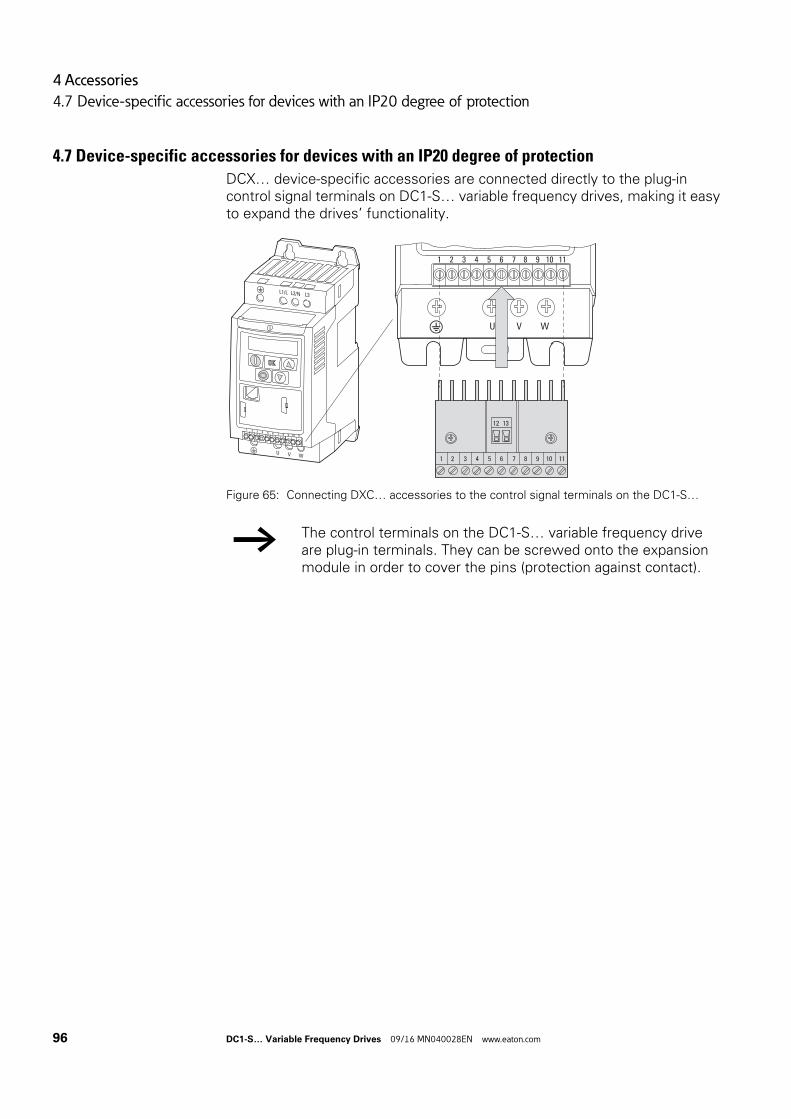
4 Accessories
4.7 Device-specific accessories for devices with an IP20 degree of protection
4.7 Device-specific accessories for devices with an IP20 degree of protection
DCX… device-specific accessories are connected directly to the plug-in control signal terminals on DC1-S… variable frequency drives, making it easy to expand the drives’ functionality.
Figure 65: Connecting DXC… accessories to the control signal terminals on the DC1-S…
→ The control terminals on the DC1-S… variable frequency drive are plug-in terminals. They can be screwed onto the expansion module in order to cover the pins (protection against contact).
1 2 3 4 5 6 7 8 9 10 11
1 2 3 4 5 6 7 8 9 10 11
12 13
L1/L L2/N L3
U V W
1 2 3 4 5 6 7 8 9 10 11
96 DC1-S… Variable Frequency Drives 09/16 MN040028EN www.eaton.com
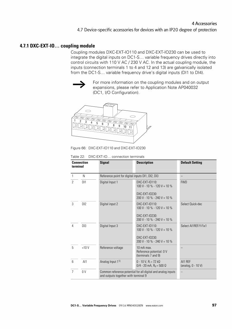
4 Accessories
4.7 Device-specific accessories for devices with an IP20 degree of protection
4.7.1 DXC-EXT-IO… coupling moduleCoupling modules DXC-EXT-IO110 and DXC-EXT-IO230 can be used to integrate the digital inputs on DC1-S… variable frequency drives directly into control circuits with 110 V AC / 230 V AC. In the actual coupling module, the inputs (connection terminals 1 to 4 and 12 and 13) are galvanically isolated from the DC1-S… variable frequency drive’s digital inputs (DI1 to DI4).
Figure 66: DXC-EXT-IO110 and DXC-EXT-IO230
Table 22: DXC-EXT-IO… connection terminals
→ For more information on the coupling modules and on output expansions, please refer to Application Note AP040032(DC1, I/O Configuration).
Connection terminal
Signal Description Default Setting
1 N Reference point for digital inputs DI1, DI2, DI3 –
2 DI1 Digital Input 1 DXC-EXT-IO110:100 V - 10 % - 120 V + 10 %
DXC-EXT-IO230:200 V - 10 % - 240 V + 10 %
FWD
3 DI2 Digital input 2 DXC-EXT-IO110:100 V - 10 % - 120 V + 10 %
DXC-EXT-IO230:200 V - 10 % - 240 V + 10 %
Select Quick-dec
4 DI3 Digital Input 3 DXC-EXT-IO110:100 V - 10 % - 120 V + 10 %
DXC-EXT-IO230:200 V - 10 % - 240 V + 10 %
Select AI1REF/f-Fix1
5 +10 V Reference voltage 10 mA max.Reference potential: 0 V(terminals 7 and 9)
–
6 AI1 Analog Input 11) 0 - 10 V, Ri > 72 kΩ0/4 - 20 mA, RB = 500 Ω
AI1 REF(analog, 0 - 10 V)
7 0 V Common reference potential for all digital and analog inputs and outputs together with terminal 9
–
1 2 3 4 5 6 7 8 9 10 11
DC1-S… Variable Frequency Drives 09/16 MN040028EN www.eaton.com 97
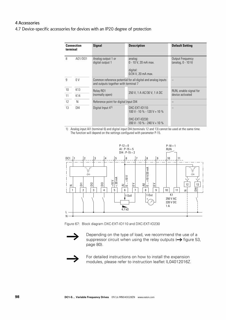
4 Accessories
4.7 Device-specific accessories for devices with an IP20 degree of protection
Figure 67: Block diagram DXC-EXT-IO110 and DXC-EXT-IO230
8 AO1/DO1 Analog output 1 or digital output 1
analog:0 - 10 V, 20 mA max.
digital:0/24 V, 20 mA max.
Output Frequency(analog, 0 - 10 V)
9 0 V Common reference potential for all digital and analog inputs and outputs together with terminal 7
–
10 K13 Relay RO1 (normally open)
250 V, 1 A AC/30 V, 1 A DCRUN, enable signal for device activated11 K14
12 N Reference point for digital input DI4 –
13 DI4 Digital Input 41) DXC-EXT-IO110:100 V - 10 % - 120 V + 10 %
DXC-EXT-IO230:200 V - 10 % - 240 V + 10 %
–
1) Analog input AI1 (terminal 6) and digital input DI4 (terminals 12 and 13) cannot be used at the same time. The function will depend on the settings configured with parameter P-15.
→ Depending on the type of load, we recommend the use of a suppressor circuit when using the relay outputs (→ figure 53, page 80).
→ For detailed instructions on how to install the expansion modules, please refer to instruction leaflet IL04012016Z.
Connection terminal
Signal Description Default Setting
2
DI1
3
DI2
4
DI3
1 5
+10
V<
20 m
A
6 7
0 V
0 V
8 9 10 11
12 13
1DC1 2 3 4 5 6 8 9 10 11
P-18 = 1RUN
P-12 = 0AI : P-15 = 5DI4 : P-15 = 2
7
AI
0 ...
+10
V
A0
0 ...
+10
V/2
0 m
A
N
DI4
N
f-Soll f-Out K1250 V AC220 V DC1 A
4.7 kΩ
+
LN
98 DC1-S… Variable Frequency Drives 09/16 MN040028EN www.eaton.com
4 Accessories
4.7 Device-specific accessories for devices with an IP20 degree of protection
NOTICE
Internal relay K1 is connected to the expansion module, meaning it can only conduct a relatively low current (≦ 1A).
DANGER
Dangerous voltage!
Expansion modules DXC-EXT-IO110 and DXC-EXT-IO230 must not be placed into operation until all mounting and installation work has been completed (plugged in and connected to the DC1-S variable frequency drive’s control signal terminals). Any other use will be considered to be an inappropriate use.
DC1-S… Variable Frequency Drives 09/16 MN040028EN www.eaton.com 99
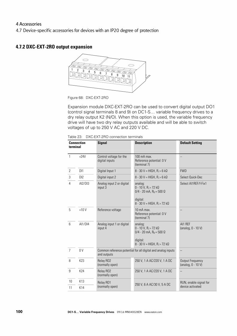
4 Accessories
4.7 Device-specific accessories for devices with an IP20 degree of protection
4.7.2 DXC-EXT-2RO output expansion
Figure 68: DXC-EXT-2RO
Expansion module DXC-EXT-2RO can be used to convert digital output DO1 (control signal terminals 8 and 9) on DC1-S… variable frequency drives to a dry relay output K2 (N/O). When this option is used, the variable frequency drive will have two dry relay outputs available and will be able to switch voltages of up to 250 V AC and 220 V DC.
Table 23: DXC-EXT-2RO connection terminals
Connection terminal
Signal Description Default Setting
1 +24V Control voltage for the digital inputs
100 mA max.Reference potential: 0 V(terminal 7)
–
2 DI1 Digital Input 1 8 - 30 V = HIGH, Ri > 6 kΩ FWD
3 DI2 Digital input 2 8 - 30 V = HIGH, Ri > 6 kΩ Select Quick-Dec
4 AI2/DI3 Analog input 2 or digital input 3
analog:0 - 10 V, Ri > 72 kΩ0/4 - 20 mA, RB = 500 Ω
digital:8 - 30 V = HIGH, Ri > 72 kΩ
Select AI1REF/f-Fix1
5 +10 V Reference voltage 10 mA max.Reference potential: 0 V(terminal 7)
–
6 AI1/DI4 Analog input 1 or digital input 4
analog:0 - 10 V, Ri > 72 kΩ0/4 - 20 mA, RB = 500 Ω
digital:8 - 30 V = HIGH, Ri > 72 kΩ
AI1 REF(analog, 0 - 10 V)
7 0 V Common reference potential for all digital and analog inputs and outputs
–
8 K23 Relay RO2 (normally open)
250 V, 1 A AC/220 V, 1 A DC Output Frequency(analog, 0 - 10 V)
9 K24 Relay RO2 (normally open)
250 V, 1 A AC/220 V, 1 A DC –
10 K13 Relay RO1 (normally open)
250 V, 6 A AC/30 V, 5 A DCRUN, enable signal for device activated11 K14
1 2 3 4 5 6 7 8 9 10 11
100 DC1-S… Variable Frequency Drives 09/16 MN040028EN www.eaton.com
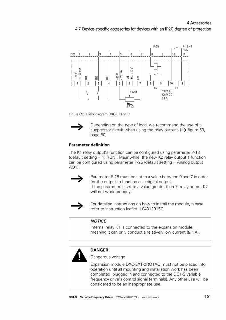
4 Accessories
4.7 Device-specific accessories for devices with an IP20 degree of protection
Figure 69: Block diagram DXC-EXT-2RO
Parameter definition
The K1 relay output’s function can be configured using parameter P-18 (default setting = 1: RUN). Meanwhile, the new K2 relay output’s function can be configured using parameter P-25 (default setting = Analog output AO1).
→ Depending on the type of load, we recommend the use of a suppressor circuit when using the relay outputs (→ figure 53, page 80).
→ Parameter P-25 must be set to a value between 0 and 7 in order for the output to function as a digital output.If the parameter is set to a value greater than 7, relay output K2 will not work properly.
→ For detailed instructions on how to install the module, please refer to instruction leaflet IL04012015Z.
NOTICE
Internal relay K1 is connected to the expansion module, meaning it can only conduct a relatively low current (≦ 1A).
DANGER
Dangerous voltage!
Expansion module DXC-EXT-2RO1AO must not be placed into operation until all mounting and installation work has been completed (plugged in and connected to the DC1-S variable frequency drive’s control signal terminals). Any other use will be considered to be an inappropriate use.
2D
I13
DI2
4
DI3
1 5
+10
V<
20 m
A
6 7
0 V
8 9 10 11
1DC1 2 3 4 5 6 8 9 10 11
P-18 = 1RUN
P-25
7
AI
0 ...
+10
V
+24
V
< 10
0 m
A
f-SollK2 K1
250 V AC220 V DC≦ 1 A
4.7 kΩ
DC1-S… Variable Frequency Drives 09/16 MN040028EN www.eaton.com 101
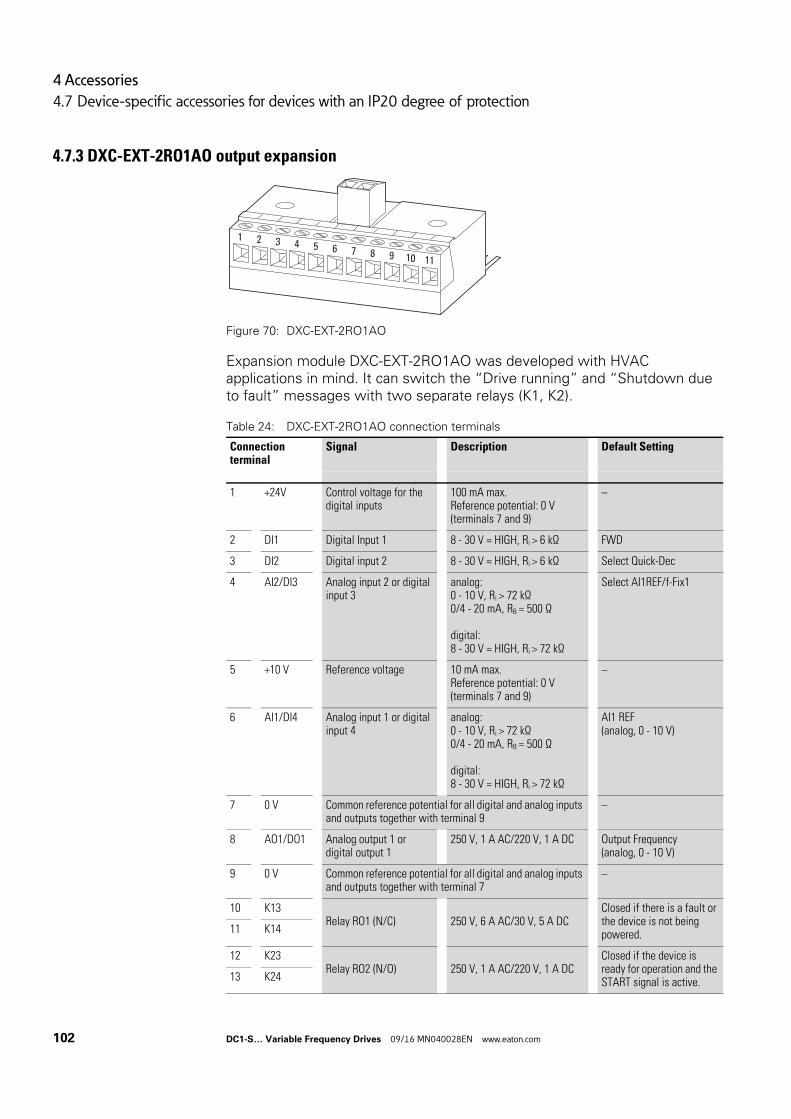
4 Accessories
4.7 Device-specific accessories for devices with an IP20 degree of protection
4.7.3 DXC-EXT-2RO1AO output expansion
Figure 70: DXC-EXT-2RO1AO
Expansion module DXC-EXT-2RO1AO was developed with HVAC applications in mind. It can switch the “Drive running” and “Shutdown due to fault” messages with two separate relays (K1, K2).
Table 24: DXC-EXT-2RO1AO connection terminals
Connection terminal
Signal Description Default Setting
1 +24V Control voltage for the digital inputs
100 mA max.Reference potential: 0 V(terminals 7 and 9)
–
2 DI1 Digital Input 1 8 - 30 V = HIGH, Ri > 6 kΩ FWD
3 DI2 Digital input 2 8 - 30 V = HIGH, Ri > 6 kΩ Select Quick-Dec
4 AI2/DI3 Analog input 2 or digital input 3
analog:0 - 10 V, Ri > 72 kΩ0/4 - 20 mA, RB = 500 Ω
digital:8 - 30 V = HIGH, Ri > 72 kΩ
Select AI1REF/f-Fix1
5 +10 V Reference voltage 10 mA max.Reference potential: 0 V(terminals 7 and 9)
–
6 AI1/DI4 Analog input 1 or digital input 4
analog:0 - 10 V, Ri > 72 kΩ0/4 - 20 mA, RB = 500 Ω
digital:8 - 30 V = HIGH, Ri > 72 kΩ
AI1 REF(analog, 0 - 10 V)
7 0 V Common reference potential for all digital and analog inputs and outputs together with terminal 9
–
8 AO1/DO1 Analog output 1 or digital output 1
250 V, 1 A AC/220 V, 1 A DC Output Frequency(analog, 0 - 10 V)
9 0 V Common reference potential for all digital and analog inputs and outputs together with terminal 7
–
10 K13 Relay RO1 (N/C) 250 V, 6 A AC/30 V, 5 A DC
Closed if there is a fault or the device is not being powered.11 K14
12 K23 Relay RO2 (N/O) 250 V, 1 A AC/220 V, 1 A DC
Closed if the device is ready for operation and the START signal is active.13 K24
1 2 3 4 5 6 7 8 9 10 11
102 DC1-S… Variable Frequency Drives 09/16 MN040028EN www.eaton.com

4 Accessories
4.7 Device-specific accessories for devices with an IP20 degree of protection
Figure 71: Block diagram DXC-EXT-2RO1AO
→ For detailed instructions on how to install the module, please refer to instruction leaflet IL04012014Z.
NOTICE
Internal relay K1 is connected to the expansion module, meaning it can only conduct a relatively low current (≦ 1A).
DANGER
Dangerous voltage!
Expansion module DXC-EXT-2RO1AO must not be placed into operation until all mounting and installation work has been completed (plugged in and connected to the DC1-S variable frequency drive’s control signal terminals). Any other use will be considered to be an inappropriate use.
2
DI1
3
DI2
4
DI3
1 5
+10
V<
20 m
A
6 7
0 V
0 V
8 9 10 11
12 13
1DC1 2 3 4 5 6 8 9 10 11
P-18 = 1READY
7
AI1
0 ...
+10
V
AO
10
... +
10 V
/20
mA
+24
V, <
100
mA
f-Soll f-Out
K1
K2
250 V AC/220 V DC, 1 A
4.7 kΩ
+
FWD
→ Depending on the type of load, we recommend the use of a suppressor circuit when using the relay outputs (→ figure 53, page 80).
DC1-S… Variable Frequency Drives 09/16 MN040028EN www.eaton.com 103
4 Accessories
4.7 Device-specific accessories for devices with an IP20 degree of protection
Parameter definition
P-18 = 1: READY, variable frequency drive ready for operation
Typical operating mode (DXC-EXT-2RO1AO control signal terminals):
• 12/13 closed → There is an enable signal for operation (FWD),READY and RUN messages: Green indicator light, for example
• 10/11 closed → Error message (not READY):Red indicator light, for example
→ P-18 can also be used to select other operating messages for the DC1-S… variable frequency drive’s internal relay (RO1)(→ “Parameter Manual” MN040022EN).
104 DC1-S… Variable Frequency Drives 09/16 MN040028EN www.eaton.com
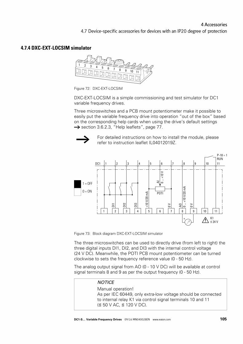
4 Accessories
4.7 Device-specific accessories for devices with an IP20 degree of protection
4.7.4 DXC-EXT-LOCSIM simulator
Figure 72: DXC-EXT-LOCSIM
DXC-EXT-LOCSIM is a simple commissioning and test simulator for DC1 variable frequency drives.
Three microswitches and a PCB mount potentiometer make it possible to easily put the variable frequency drive into operation “out of the box” based on the corresponding help cards when using the drive’s default settings → section 3.6.2.3, “Help leaflets”, page 77.
Figure 73: Block diagram DXC-EXT-LOCSIM simulator
The three microswitches can be used to directly drive (from left to right) the three digital inputs DI1, DI2, and DI3 with the internal control voltage (24 V DC). Meanwhile, the POTI PCB mount potentiometer can be turned clockwise to sets the frequency reference value (0 - 50 Hz).
The analog output signal from AO (0 - 10 V DC) will be available at control signal terminals 8 and 9 as per the output frequency (0 - 50 Hz).
→ For detailed instructions on how to install the module, please refer to instruction leaflet IL04012019Z.
1 = OFF
0 = ON
NOTICE
Manual operation!As per IEC 60449, only extra-low voltage should be connected to internal relay K1 via control signal terminals 10 and 11 (≦ 50 V AC, ≦ 120 V DC).
1 2 3 4 5 6 7 8 9 10 11
2
DI1
3
DI2
4
DI3
1 5
+10
V/2
0 m
A
6
POTI
7
0 V
8
AO
0 ...
+10
V/2
0 m
A
9
0 V
10 11
1DC1 2 3 4 5 6 8 9 10 11
P-18 = 1RUN
7
+ K1≦ 24 V
AI
0 ...
+10
V
DC1-S… Variable Frequency Drives 09/16 MN040028EN www.eaton.com 105
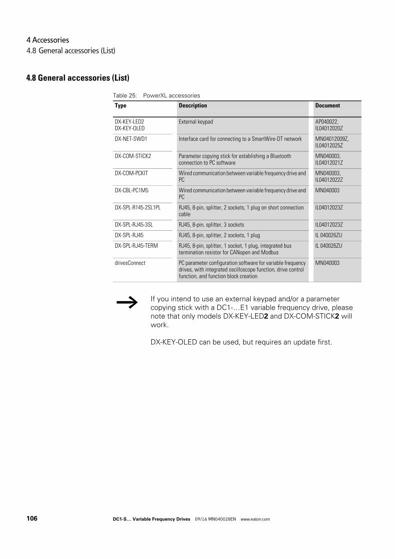
4 Accessories
4.8 General accessories (List)
4.8 General accessories (List)
Table 25: PowerXL accessories
Type Description Document
DX-KEY-LED2DX-KEY-OLED
External keypad AP040022,IL04012020Z
DX-NET-SWD1 Interface card for connecting to a SmartWire-DT network MN04012009Z,IL04012025Z
DX-COM-STICK2 Parameter copying stick for establishing a Bluetooth connection to PC software
MN040003,IL04012021Z
DX-COM-PCKIT Wired communication between variable frequency drive and PC
MN040003,IL04012022Z
DX-CBL-PC1M5 Wired communication between variable frequency drive and PC
MN040003
DX-SPL-R145-2SL1PL RJ45, 8-pin, splitter, 2 sockets, 1 plug on short connection cable
lL04012023Z
DX-SPL-RJ45-3SL RJ45, 8-pin, splitter, 3 sockets lL04012023Z
DX-SPL-RJ45 RJ45, 8-pin, splitter, 2 sockets, 1 plug IL 040026ZU
DX-SPL-RJ45-TERM RJ45, 8-pin, splitter, 1 socket, 1 plug, integrated bus termination resistor for CANopen and Modbus
IL 040026ZU
drivesConnect PC parameter configuration software for variable frequency drives, with integrated oscilloscope function, drive control function, and function block creation
MN040003
→ If you intend to use an external keypad and/or a parameter copying stick with a DC1-…E1 variable frequency drive, please note that only models DX-KEY-LED2 and DX-COM-STICK2 will work.
DX-KEY-OLED can be used, but requires an update first.
106 DC1-S… Variable Frequency Drives 09/16 MN040028EN www.eaton.com
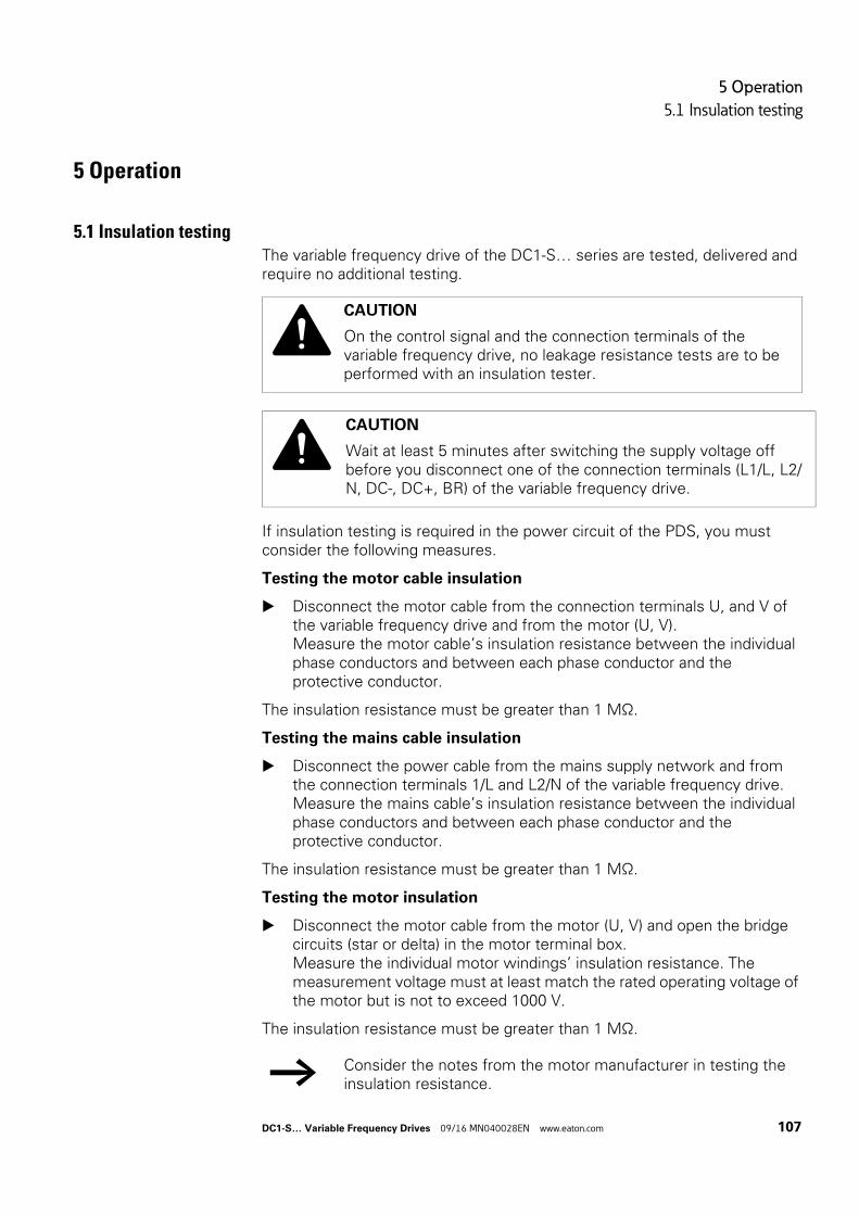
5 Operation
5.1 Insulation testing
5 Operation
5.1 Insulation testingThe variable frequency drive of the DC1-S… series are tested, delivered and require no additional testing.
If insulation testing is required in the power circuit of the PDS, you must consider the following measures.
Testing the motor cable insulation
Disconnect the motor cable from the connection terminals U, and V of the variable frequency drive and from the motor (U, V).Measure the motor cable’s insulation resistance between the individual phase conductors and between each phase conductor and the protective conductor.
The insulation resistance must be greater than 1 MΩ.
Testing the mains cable insulation
Disconnect the power cable from the mains supply network and from the connection terminals 1/L and L2/N of the variable frequency drive.Measure the mains cable’s insulation resistance between the individual phase conductors and between each phase conductor and the protective conductor.
The insulation resistance must be greater than 1 MΩ.
Testing the motor insulation
Disconnect the motor cable from the motor (U, V) and open the bridge circuits (star or delta) in the motor terminal box.Measure the individual motor windings’ insulation resistance. The measurement voltage must at least match the rated operating voltage of the motor but is not to exceed 1000 V.
The insulation resistance must be greater than 1 MΩ.
CAUTION
On the control signal and the connection terminals of the variable frequency drive, no leakage resistance tests are to be performed with an insulation tester.
CAUTION
Wait at least 5 minutes after switching the supply voltage off before you disconnect one of the connection terminals (L1/L, L2/N, DC-, DC+, BR) of the variable frequency drive.
→ Consider the notes from the motor manufacturer in testing the insulation resistance.
DC1-S… Variable Frequency Drives 09/16 MN040028EN www.eaton.com 107
5 Operation
5.2 Protection against electric shock
5.2 Protection against electric shock
Ensuring protection against electric shock when using DC1-S… variable frequency drives, as per IEC/EN 61800-5-1
Manufacturer’s declaration for the initial verification as per IEC/HD 60364-6 (DIN VDE 0100-600 (VDE 0100-600)) and for periodic testing as per EN 50110-1 (DIN VDE 0105-100 (VDE 0105-100))
Fault protection in accordance with IEC/HD 60364-4-41 (DIN VDE 0100-410 (VDE 0100-410)) for the output-side circuits of the aforementioned apparatus is guaranteed provided that the following requirements are met:
• The installation instructions in this documentation have been observed.• The applicable standards in the IEC/HD 60364 (DIN VDE 0100
(VDE 0100) series have been observed.• The continuity of all associated protective conductors and equipotential
bonding conductors, including the corresponding connection points, has been ensured.
Provided that the above requirements are met, the aforementioned apparatus meets the requirements in IEC/HD 60364-4-41 (DIN VDE 0100-410 (VDE 0100-410):2007-06, section 411.3.2.5) when using the “automatic power supply shutdown” protective measure.
The note is based on the following information:
In the event of a short-circuit with negligible impedance to a protective conductor or to earth, the aforementioned apparatus will reduce the output voltage within a time as required in table 41.1 or within 5 seconds – depending on the applicable scenario – as per IEC/HD 60364-41 (DIN VDE 0100-410; VDE 0100-410):2007-06).
108 DC1-S… Variable Frequency Drives 09/16 MN040028EN www.eaton.com
5 Operation
5.3 Checklist for commissioning
5.3 Checklist for commissioning
Before placing the frequency converter into operation, use the checklist below to make sure that all the following requirements are met:
No. Activity Note
1 Mounting and wiring have been carried out in accordance with the corresponding instruction leaflet (→ IL04020014Z (IP20) and IL040001Z (IP66)).
2 All wiring and line section leftovers, as well as all the tools used, have been removed from the variable frequency drive’s proximity.
3 All terminals in the power section and in the control section were tightened with the specified torque.
4 The lines connected to the output terminals (U, V, DC+, DC-, BR) of the variable frequency drive are not short-circuited and are not connected to earth (PE).
5 The variable frequency drive has been earthed properly (PE).
6 All electrical connections in the power section (L1/L, L2/N, U, V, DC+, DC-, BR, PE) have been connected properly while taking into account the degree of protection and have been dimensioned in line with the corresponding requirements.
7 Each single phase of the supply voltage (L or L1, L2) is protected with a fuse.
8 The variable frequency drive and the motor are adapted to the mains voltage (→ section 1.4.1, “Rated operational data on the nameplate”, page 12).
9 The quality and volume of cooling air are in line with the environmental conditions required for the variable frequency drive and the motor.
10 All connected control cables comply with the corresponding stop conditions (e.g., switch in OFF position and setpoint value = zero).
11 The parameters preset at the factory have been checked with the list of parameters (→ section 6.6, “Parameter”, page 142 ff.).
12 The effective direction of a coupled machine will allow the motor to start.
13 All emergency switching off functions and safety functions are in an appropriate condition.
DC1-S… Variable Frequency Drives 09/16 MN040028EN www.eaton.com 109
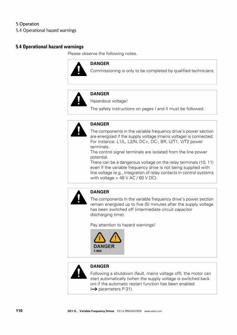
5 Operation
5.4 Operational hazard warnings
5.4 Operational hazard warnings
Please observe the following notes.
DANGER
Commissioning is only to be completed by qualified technicians.
DANGER
Hazardous voltage!
The safety instructions on pages I and II must be followed.
DANGER
The components in the variable frequency drive’s power section are energized if the supply voltage (mains voltage) is connected. For instance: L1/L, L2/N, DC+, DC-, BR, U/T1, V/T2 power terminals.The control signal terminals are isolated from the line power potential.There can be a dangerous voltage on the relay terminals (10, 11) even if the variable frequency drive is not being supplied with line voltage (e.g., integration of relay contacts in control systems with voltage > 48 V AC / 60 V DC).
DANGER
The components in the variable frequency drive’s power section remain energized up to five (5) minutes after the supply voltage has been switched off (intermediate circuit capacitor discharging time).
Pay attention to hazard warnings!
DANGER
Following a shutdown (fault, mains voltage off), the motor can start automatically (when the supply voltage is switched back on) if the automatic restart function has been enabled (→ parameters P-31).
110 DC1-S… Variable Frequency Drives 09/16 MN040028EN www.eaton.com
5 Operation
5.4 Operational hazard warnings
NOTICE
Any contactors and switching devices on the line side are not to be opened during motor operation. Inching operation using the mains contactor is not permitted.
Contactors and switchgear (repair and maintenance switches) on the motor side must not be opened while the motor is in operation.Inching operation of the motor with contactors and switching devices in the output of the variable frequency drive is not permissible.
NOTICE
Make sure that starting the motor will not put anyone or anything in danger.Disconnect the driven machine if there is a danger in an incorrect operating state.
→ If motors are to be operated with frequencies higher than the standard 50 or 60 Hz, then these operating ranges must be approved by the motor manufacturer. The motors could be damaged otherwise.
DC1-S… Variable Frequency Drives 09/16 MN040028EN www.eaton.com 111
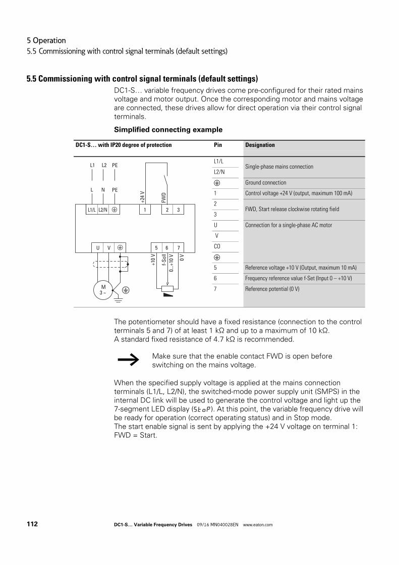
5 Operation
5.5 Commissioning with control signal terminals (default settings)
5.5 Commissioning with control signal terminals (default settings)
DC1-S… variable frequency drives come pre-configured for their rated mains voltage and motor output. Once the corresponding motor and mains voltage are connected, these drives allow for direct operation via their control signal terminals.
Simplified connecting example
The potentiometer should have a fixed resistance (connection to the control terminals 5 and 7) of at least 1 kΩ and up to a maximum of 10 kΩ.A standard fixed resistance of 4.7 kΩ is recommended.
When the specified supply voltage is applied at the mains connection terminals (L1/L, L2/N), the switched-mode power supply unit (SMPS) in the internal DC link will be used to generate the control voltage and light up the 7-segment LED display (StoP). At this point, the variable frequency drive will be ready for operation (correct operating status) and in Stop mode.The start enable signal is sent by applying the +24 V voltage on terminal 1: FWD = Start.
DC1-S… with IP20 degree of protection Pin Designation
L1/LSingle-phase mains connection
L2/N
Ground connection
1 Control voltage +24 V (output, maximum 100 mA)
2FWD, Start release clockwise rotating field
3
U Connection for a single-phase AC motor
V
CO
5 Reference voltage +10 V (Output, maximum 10 mA)
6 Frequency reference value f-Set (Input 0 – +10 V)
7 Reference potential (0 V)
VU
M3 ~
6 75
1 2 3
+24
V
FWD
0...+
10 V 0 V
+10
V
L1/L L2/N
L N
L1 L2f-
Sol
l
PE
PE
→ Make sure that the enable contact FWD is open before switching on the mains voltage.
112 DC1-S… Variable Frequency Drives 09/16 MN040028EN www.eaton.com
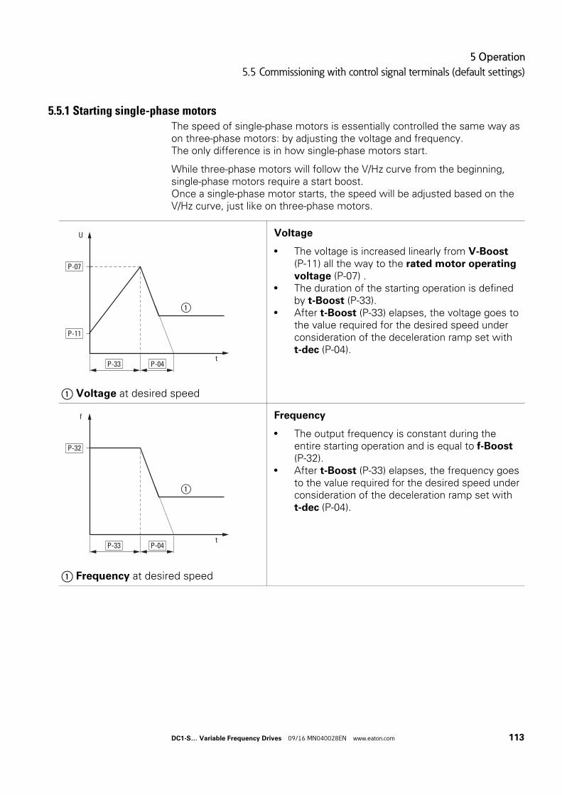
5 Operation
5.5 Commissioning with control signal terminals (default settings)
5.5.1 Starting single-phase motorsThe speed of single-phase motors is essentially controlled the same way as on three-phase motors: by adjusting the voltage and frequency.The only difference is in how single-phase motors start.
While three-phase motors will follow the V/Hz curve from the beginning, single-phase motors require a start boost.Once a single-phase motor starts, the speed will be adjusted based on theV/Hz curve, just like on three-phase motors.
① Voltage at desired speed
Voltage
• The voltage is increased linearly from V-Boost (P-11) all the way to the rated motor operating voltage (P-07) .
• The duration of the starting operation is defined by t-Boost (P-33).
• After t-Boost (P-33) elapses, the voltage goes to the value required for the desired speed under consideration of the deceleration ramp set with t-dec (P-04).
① Frequency at desired speed
Frequency
• The output frequency is constant during the entire starting operation and is equal to f-Boost (P-32).
• After t-Boost (P-33) elapses, the frequency goes to the value required for the desired speed under consideration of the deceleration ramp set with t-dec (P-04).
U
P-07
t
①
P-11
P-33 P-04
f
P-32
t
①
P-33 P-04
DC1-S… Variable Frequency Drives 09/16 MN040028EN www.eaton.com 113
5 Operation
5.5 Commissioning with control signal terminals (default settings)
5.5.2 Start-UpPrerequisite:These instructions assume that the variable frequency drive has its default settings at the beginning of the commissioning process.
Make sure that the motor is connected correctly and will not pose any hazards when running.The motor must have a load during the commissioning process so that it will be possible to determine the right values.
Enter the password in P-14 (default setting: 101) in order to allow access to “parameter level 2.”
Set the values for the rated motor operating voltage (P-07) and rated motor operational current (P-08) parameters to the values on the motor nameplate.
5.5.2.1 V-Boost (P-11) Set the t-Boost (P-33) parameter to the maximum possible value
(150.0 s). This will allow the voltage to increase slowly and make it possible to easily adjust the start voltage and the startup behavior.
Start the drive. Press the OK button as many times as necessary until the current, “A…xxx”, is displayed.The current should increase quickly, stabilize after a few seconds, and then start increasing slowly. Monitor the current’s value for approx. 3 to 5 seconds after starting.
• If the current is less than 80 % of the rated motor current: Switch off the drive. Increase the value in P-11. Repeat the test.
• If the current is greater than 90 % of the rated motor current: Switch off the drive. Reduce the value in P-11. Repeat the test.
When P-11 is set correctly, the current should be 80 to 90 % of the rated motor current for 3 to 5 seconds after starting.
→ It is possible for the motor not to rotate during the adjustment procedure. You can safely ignore this, as the procedure is used only to determine the correct value for V-Boost (P-11).
114 DC1-S… Variable Frequency Drives 09/16 MN040028EN www.eaton.com
5 Operation
5.5 Commissioning with control signal terminals (default settings)
5.5.2.2 t-Boost (P-33)Once you have determined the correct value for V-Boost, you will need to adjust the t-Boost (P-33) parameter. This can be done in large increments of approximately 50 % until you are close to the required value.
The ideal duration is approx. 1 to 2 seconds longer than the duration required in order to bring the motor to full speed.
Make sure that the correct value for V-Boost (P-11), as determined with the procedure described in → section 5.5.2.1, “V-Boost (P-11)”, is set.
Select a speed reference value that is lower than the maximum value. This will make it possible to recognize the end of t-Boost, as the motor will then decelerate to the set speed.
Start the drive. Press the OK button as many times as necessary until the current, “A…xxx”, is displayed.
Check whether the motor starts with a rising voltage.After the motor starts, the current will increase. As soon as the motor reaches its full speed, the current will decrease rapidly. If the time set with t-Boost is too long, the voltage at this point will still be relatively low and the motor will be rotating with a high current.
Determine the time between the moment the motor starts and the moment it reaches full speed.
Reduce the t-Boost value and repeat the test. If the motor reaches its full speed before t-Boost elapses, keep
reducing the value of t-Boost and repeating the test.It is not uncommon for the O-I and It.trp faults to occur during this testing phase. If the device trips, wait at least 30 seconds before running the test again.
If the value of t-Boost is too large, the motor will continue to run with a reduced voltage and, accordingly, a higher current for some time after starting. If this occurs, reduce the value of t-Boost (P-33).
5.5.2.3 f-Boost (P-32)In most cases, f-Boost (P-32) will be equal to the rated motor frequency (P-09) and will not need to be adjusted during commissioning.If necessary, however, the value can be changed.
DC1-S… Variable Frequency Drives 09/16 MN040028EN www.eaton.com 115
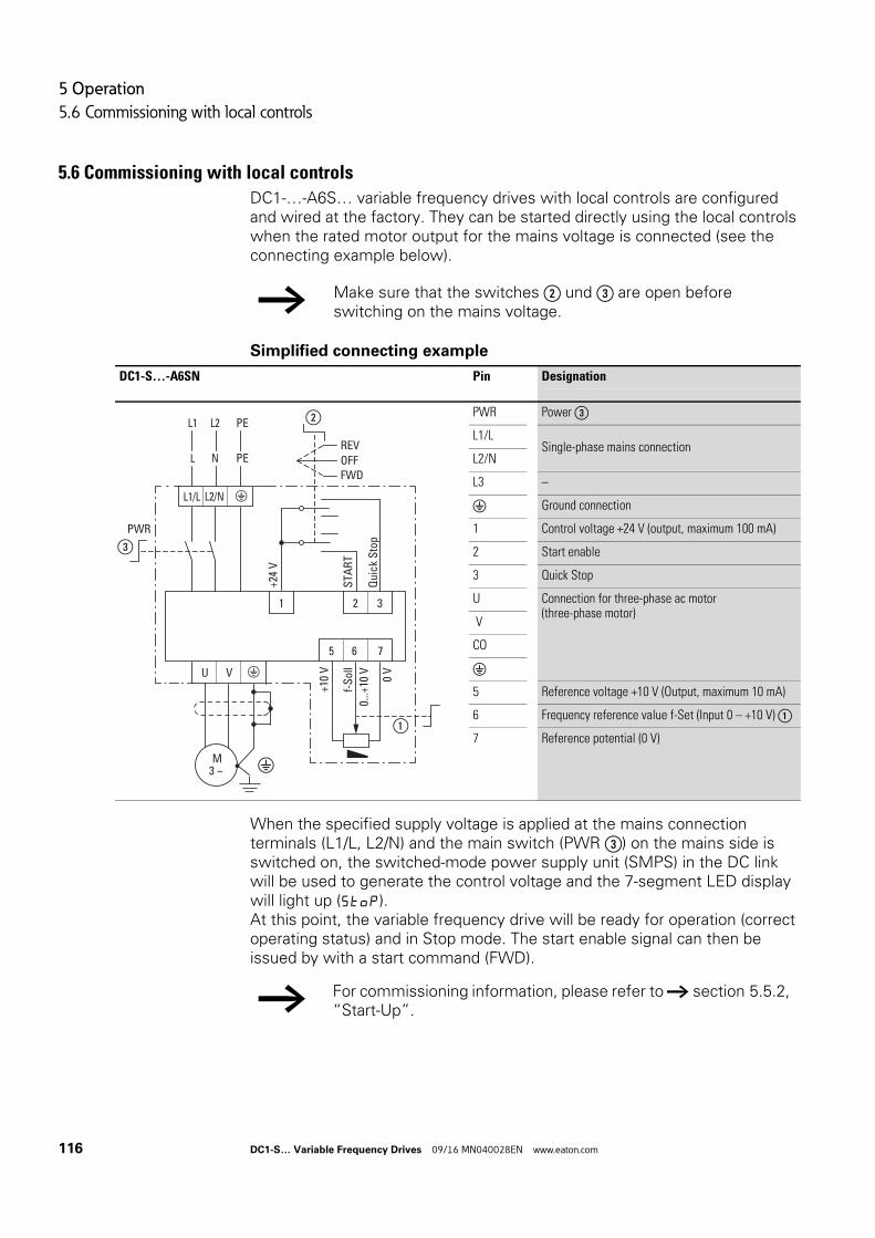
5 Operation
5.6 Commissioning with local controls
5.6 Commissioning with local controls
DC1-…-A6S… variable frequency drives with local controls are configured and wired at the factory. They can be started directly using the local controls when the rated motor output for the mains voltage is connected (see the connecting example below).
Simplified connecting example
When the specified supply voltage is applied at the mains connection terminals (L1/L, L2/N) and the main switch (PWR ③) on the mains side is switched on, the switched-mode power supply unit (SMPS) in the DC link will be used to generate the control voltage and the 7-segment LED display will light up (StoP).At this point, the variable frequency drive will be ready for operation (correct operating status) and in Stop mode. The start enable signal can then be issued by with a start command (FWD).
→ Make sure that the switches ② und ③ are open before switching on the mains voltage.
DC1-S…-A6SN Pin Designation
PWR Power ③
L1/LSingle-phase mains connection
L2/N
L3 –
Ground connection
1 Control voltage +24 V (output, maximum 100 mA)
2 Start enable
3 Quick Stop
U Connection for three-phase ac motor(three-phase motor)
V
CO
5 Reference voltage +10 V (Output, maximum 10 mA)
6 Frequency reference value f-Set (Input 0 – +10 V) ①
7 Reference potential (0 V)
6 75
1 2 3
0...+
10 V 0 V
+10
V
f-S
oll
①
+24
V
STA
RT
Qui
ck S
top
L1/L
REVOFFFWD
L2/N
PWR
③
②
L N
L1 L2
PE
PE
VU
M3 ~
→ For commissioning information, please refer to → section 5.5.2, “Start-Up”.
116 DC1-S… Variable Frequency Drives 09/16 MN040028EN www.eaton.com
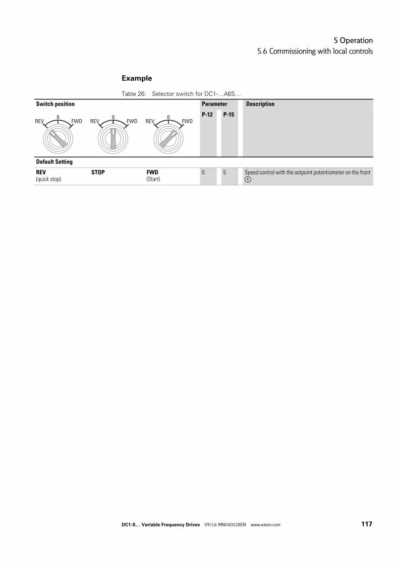
5 Operation
5.6 Commissioning with local controls
Example
Table 26: Selector switch for DC1-…A6S…
Switch position Parameter Description
P-12 P-15
Default Setting
REV(quick stop)
STOP FWD(Start)
0 5 Speed control with the setpoint potentiometer on the front ①
REV FWD0
REV FWD0
REV FWD0
DC1-S… Variable Frequency Drives 09/16 MN040028EN www.eaton.com 117
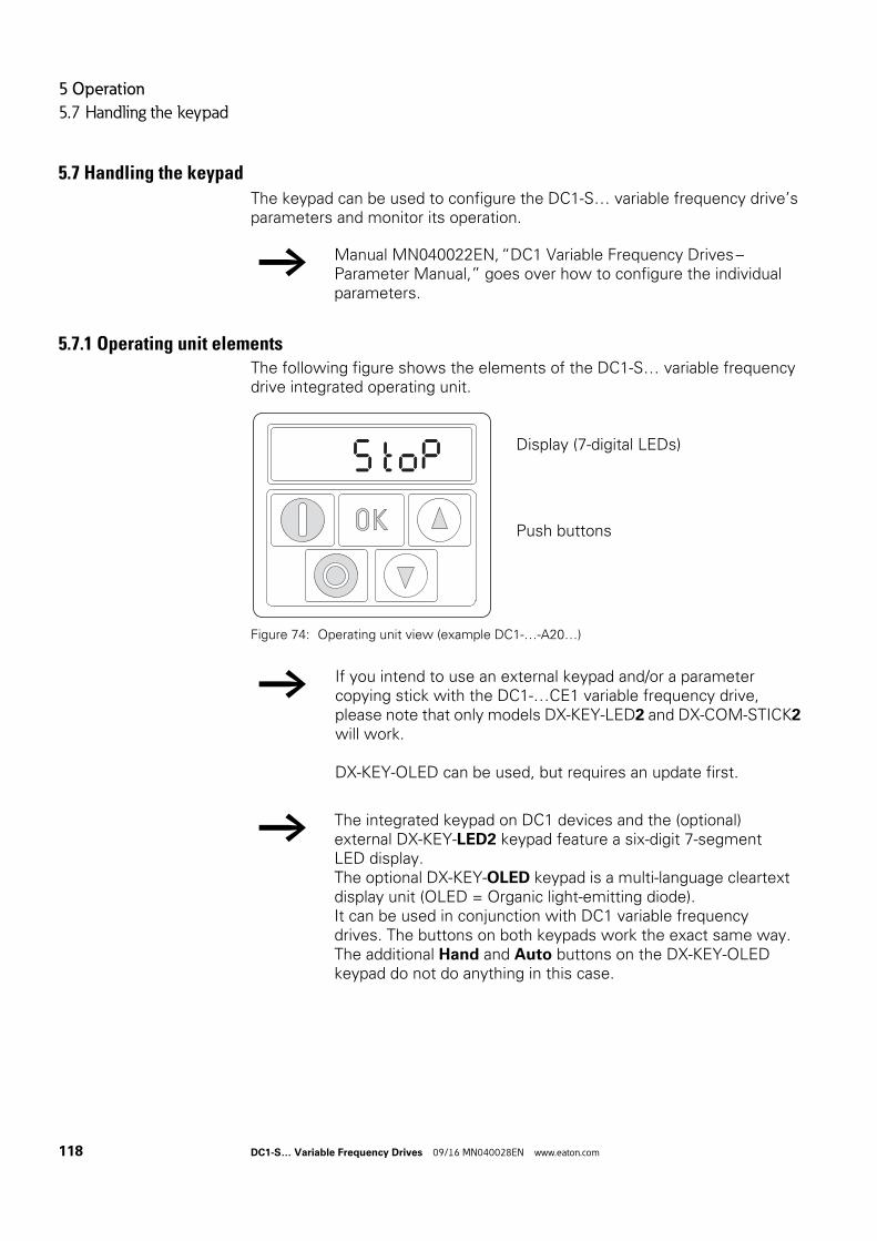
5 Operation
5.7 Handling the keypad
5.7 Handling the keypad
The keypad can be used to configure the DC1-S… variable frequency drive’s parameters and monitor its operation.
5.7.1 Operating unit elementsThe following figure shows the elements of the DC1-S… variable frequency drive integrated operating unit.
Figure 74: Operating unit view (example DC1-…-A20…)
→ Manual MN040022EN, “DC1 Variable Frequency Drives – Parameter Manual,” goes over how to configure the individual parameters.
Display (7-digital LEDs)
Push buttons
→ If you intend to use an external keypad and/or a parameter copying stick with the DC1-…CE1 variable frequency drive, please note that only models DX-KEY-LED2 and DX-COM-STICK2 will work.
DX-KEY-OLED can be used, but requires an update first.
→ The integrated keypad on DC1 devices and the (optional) external DX-KEY-LED2 keypad feature a six-digit 7-segment LED display.The optional DX-KEY-OLED keypad is a multi-language cleartext display unit (OLED = Organic light-emitting diode).It can be used in conjunction with DC1 variable frequency drives. The buttons on both keypads work the exact same way.The additional Hand and Auto buttons on the DX-KEY-OLED keypad do not do anything in this case.
118 DC1-S… Variable Frequency Drives 09/16 MN040028EN www.eaton.com
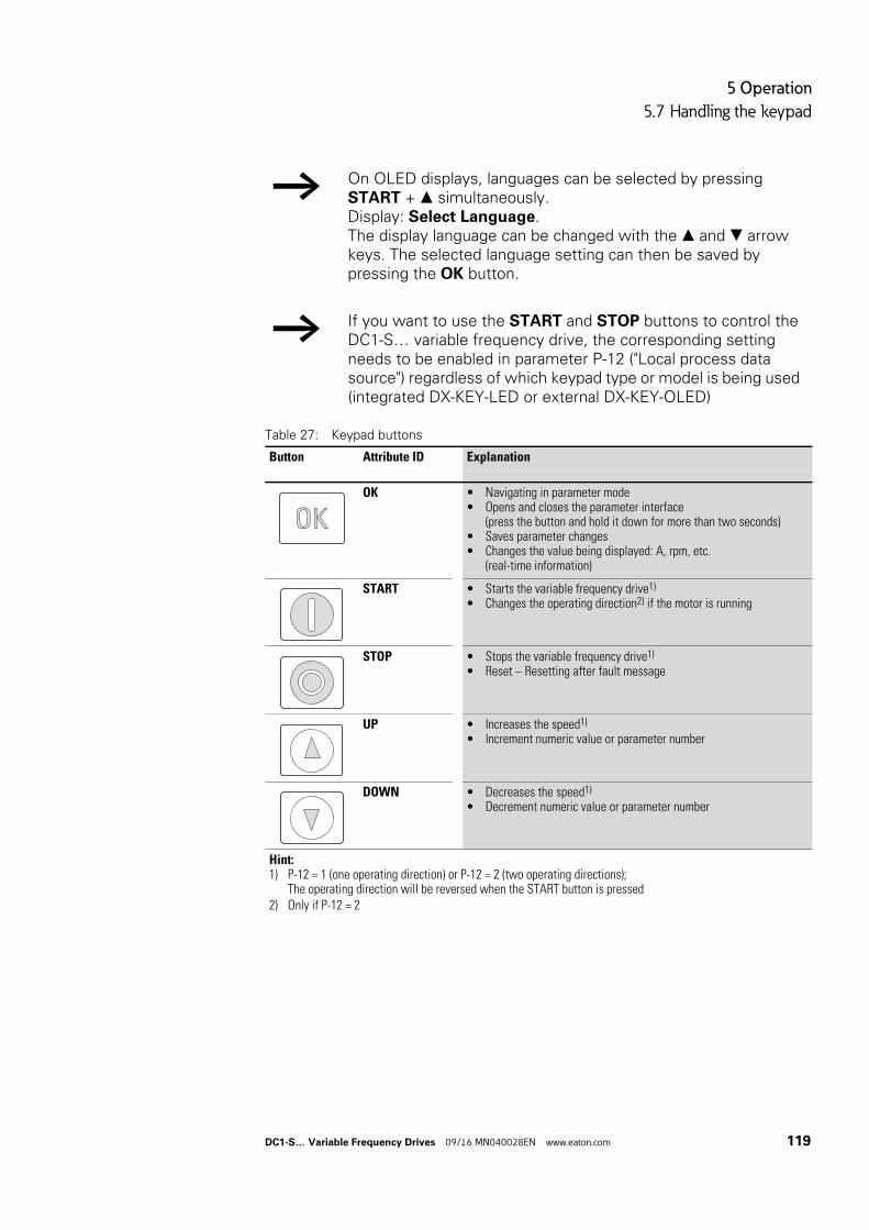
5 Operation
5.7 Handling the keypad
Table 27: Keypad buttons
→ On OLED displays, languages can be selected by pressing START + simultaneously.Display: Select Language.The display language can be changed with the and arrow keys. The selected language setting can then be saved by pressing the OK button.
→ If you want to use the START and STOP buttons to control the DC1-S… variable frequency drive, the corresponding setting needs to be enabled in parameter P-12 ("Local process data source") regardless of which keypad type or model is being used (integrated DX-KEY-LED or external DX-KEY-OLED)
Button Attribute ID Explanation
OK • Navigating in parameter mode• Opens and closes the parameter interface
(press the button and hold it down for more than two seconds)• Saves parameter changes• Changes the value being displayed: A, rpm, etc.
(real-time information)
START • Starts the variable frequency drive1)
• Changes the operating direction2) if the motor is running
STOP • Stops the variable frequency drive1)
• Reset – Resetting after fault message
UP • Increases the speed1)
• Increment numeric value or parameter number
DOWN • Decreases the speed1)
• Decrement numeric value or parameter number
Hint:1) P-12 = 1 (one operating direction) or P-12 = 2 (two operating directions);
The operating direction will be reversed when the START button is pressed2) Only if P-12 = 2
DC1-S… Variable Frequency Drives 09/16 MN040028EN www.eaton.com 119

5 Operation
5.7 Handling the keypad
120 DC1-S… Variable Frequency Drives 09/16 MN040028EN www.eaton.com
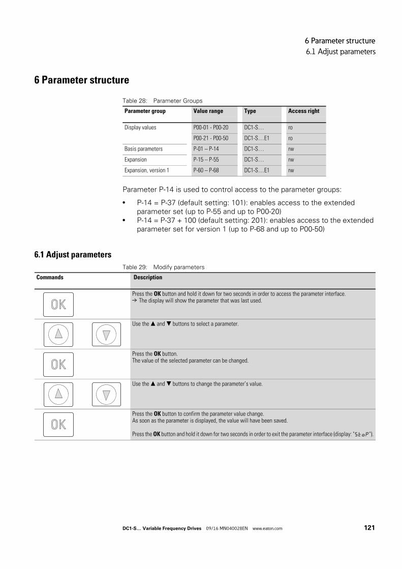
6 Parameter structure
6.1 Adjust parameters
6 Parameter structure
Table 28: Parameter Groups
Parameter P-14 is used to control access to the parameter groups:
• P-14 = P-37 (default setting: 101): enables access to the extended parameter set (up to P-55 and up to P00-20)
• P-14 = P-37 + 100 (default setting: 201): enables access to the extended parameter set for version 1 (up to P-68 and up to P00-50)
6.1 Adjust parameters
Table 29: Modify parameters
Parameter group Value range Type Access right
Display values P00-01 - P00-20 DC1-S… ro
P00-21 - P00-50 DC1-S…E1 ro
Basis parameters P-01 – P-14 DC1-S… rw
Expansion P-15 – P-55 DC1-S… rw
Expansion, version 1 P-60 – P-68 DC1-S…E1 rw
Commands Description
Press the OK button and hold it down for two seconds in order to access the parameter interface.→ The display will show the parameter that was last used.
Use the and buttons to select a parameter.
Press the OK button.The value of the selected parameter can be changed.
Use the and buttons to change the parameter’s value.
Press the OK button to confirm the parameter value change.As soon as the parameter is displayed, the value will have been saved.
Press the OK button and hold it down for two seconds in order to exit the parameter interface (display: "Stop").
DC1-S… Variable Frequency Drives 09/16 MN040028EN www.eaton.com 121
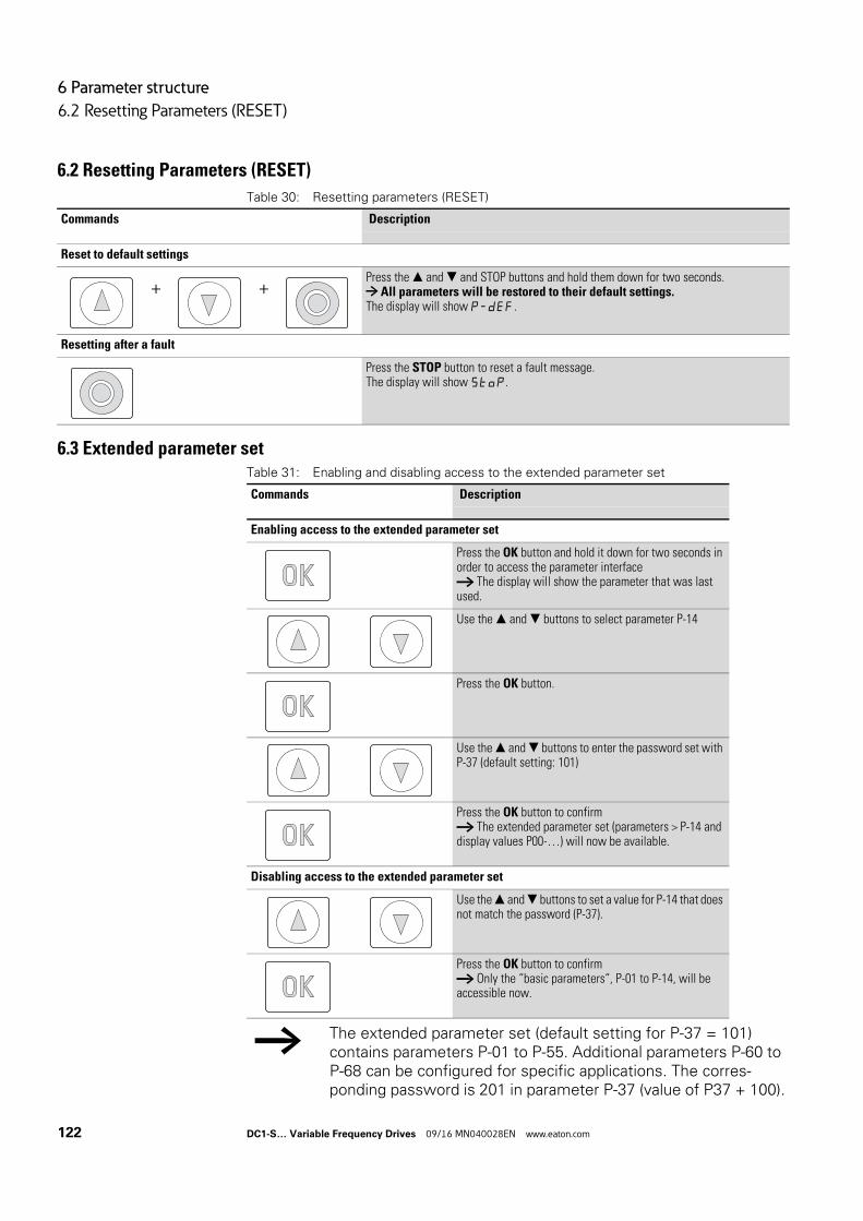
6 Parameter structure
6.2 Resetting Parameters (RESET)
6.2 Resetting Parameters (RESET)
Table 30: Resetting parameters (RESET)
6.3 Extended parameter setTable 31: Enabling and disabling access to the extended parameter set
Commands Description
Reset to default settings
+ +Press the and and STOP buttons and hold them down for two seconds.→ All parameters will be restored to their default settings.The display will show P-dEF.
Resetting after a fault
Press the STOP button to reset a fault message.The display will show StoP.
Commands Description
Enabling access to the extended parameter set
Press the OK button and hold it down for two seconds in order to access the parameter interface→ The display will show the parameter that was last used.
Use the and buttons to select parameter P-14
Press the OK button.
Use the and buttons to enter the password set with P-37 (default setting: 101)
Press the OK button to confirm→ The extended parameter set (parameters > P-14 and display values P00-…) will now be available.
Disabling access to the extended parameter set
Use the and buttons to set a value for P-14 that does not match the password (P-37).
Press the OK button to confirm→ Only the “basic parameters“, P-01 to P-14, will be accessible now.
→ The extended parameter set (default setting for P-37 = 101) contains parameters P-01 to P-55. Additional parameters P-60 to P-68 can be configured for specific applications. The corres-ponding password is 201 in parameter P-37 (value of P37 + 100).
122 DC1-S… Variable Frequency Drives 09/16 MN040028EN www.eaton.com
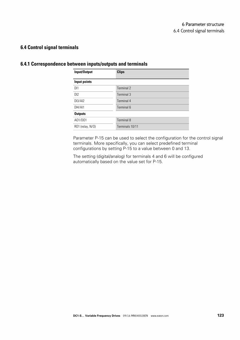
6 Parameter structure
6.4 Control signal terminals
6.4 Control signal terminals
6.4.1 Correspondence between inputs/outputs and terminals
Parameter P-15 can be used to select the configuration for the control signal terminals. More specifically, you can select predefined terminal configurations by setting P-15 to a value between 0 and 13.
The setting (digital/analog) for terminals 4 and 6 will be configured automatically based on the value set for P-15.
Input/Output Clips
Input points
DI1 Terminal 2
DI2 Terminal 3
DI3/AI2 Terminal 4
DI4/AI1 Terminal 6
Outputs
AO1/DO1 Terminal 8
RO1 (relay, N/O) Terminals 10/11
DC1-S… Variable Frequency Drives 09/16 MN040028EN www.eaton.com 123
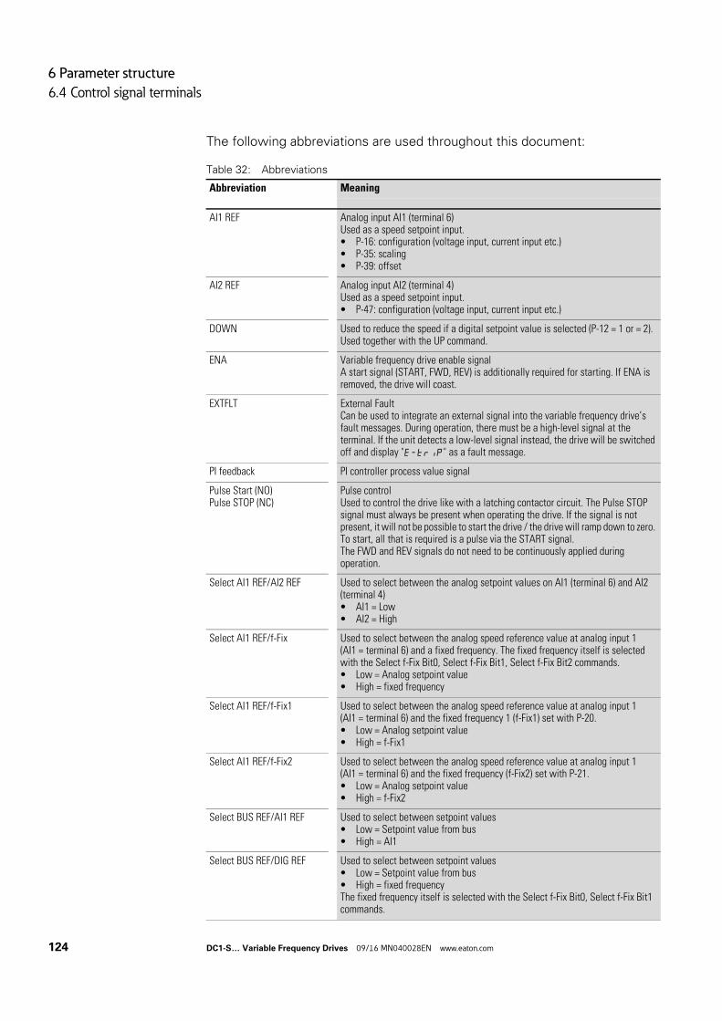
6 Parameter structure
6.4 Control signal terminals
The following abbreviations are used throughout this document:
Table 32: Abbreviations
Abbreviation Meaning
AI1 REF Analog input AI1 (terminal 6)Used as a speed setpoint input.• P-16: configuration (voltage input, current input etc.)• P-35: scaling• P-39: offset
AI2 REF Analog input AI2 (terminal 4)Used as a speed setpoint input.• P-47: configuration (voltage input, current input etc.)
DOWN Used to reduce the speed if a digital setpoint value is selected (P-12 = 1 or = 2). Used together with the UP command.
ENA Variable frequency drive enable signalA start signal (START, FWD, REV) is additionally required for starting. If ENA is removed, the drive will coast.
EXTFLT External FaultCan be used to integrate an external signal into the variable frequency drive’s fault messages. During operation, there must be a high-level signal at the terminal. If the unit detects a low-level signal instead, the drive will be switched off and display "E-trip" as a fault message.
PI feedback PI controller process value signal
Pulse Start (NO)Pulse STOP (NC)
Pulse controlUsed to control the drive like with a latching contactor circuit. The Pulse STOP signal must always be present when operating the drive. If the signal is not present, it will not be possible to start the drive / the drive will ramp down to zero. To start, all that is required is a pulse via the START signal.The FWD and REV signals do not need to be continuously applied during operation.
Select AI1 REF/AI2 REF Used to select between the analog setpoint values on AI1 (terminal 6) and AI2 (terminal 4)• AI1 = Low• AI2 = High
Select AI1 REF/f-Fix Used to select between the analog speed reference value at analog input 1 (AI1 = terminal 6) and a fixed frequency. The fixed frequency itself is selected with the Select f-Fix Bit0, Select f-Fix Bit1, Select f-Fix Bit2 commands.• Low = Analog setpoint value• High = fixed frequency
Select AI1 REF/f-Fix1 Used to select between the analog speed reference value at analog input 1 (AI1 = terminal 6) and the fixed frequency 1 (f-Fix1) set with P-20.• Low = Analog setpoint value• High = f-Fix1
Select AI1 REF/f-Fix2 Used to select between the analog speed reference value at analog input 1 (AI1 = terminal 6) and the fixed frequency (f-Fix2) set with P-21.• Low = Analog setpoint value• High = f-Fix2
Select BUS REF/AI1 REF Used to select between setpoint values• Low = Setpoint value from bus• High = AI1
Select BUS REF/DIG REF Used to select between setpoint values• Low = Setpoint value from bus• High = fixed frequencyThe fixed frequency itself is selected with the Select f-Fix Bit0, Select f-Fix Bit1 commands.
124 DC1-S… Variable Frequency Drives 09/16 MN040028EN www.eaton.com
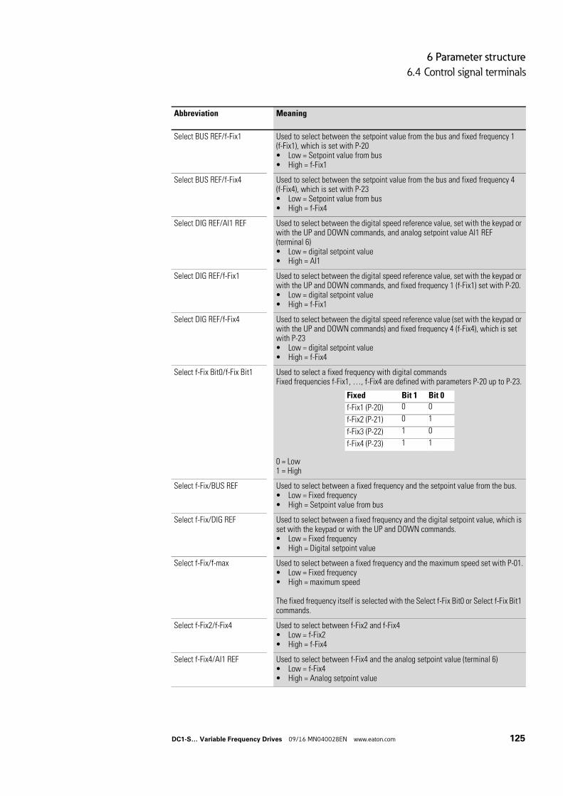
6 Parameter structure
6.4 Control signal terminals
Select BUS REF/f-Fix1 Used to select between the setpoint value from the bus and fixed frequency 1 (f-Fix1), which is set with P-20• Low = Setpoint value from bus• High = f-Fix1
Select BUS REF/f-Fix4 Used to select between the setpoint value from the bus and fixed frequency 4 (f-Fix4), which is set with P-23• Low = Setpoint value from bus• High = f-Fix4
Select DIG REF/AI1 REF Used to select between the digital speed reference value, set with the keypad or with the UP and DOWN commands, and analog setpoint value AI1 REF (terminal 6)• Low = digital setpoint value• High = AI1
Select DIG REF/f-Fix1 Used to select between the digital speed reference value, set with the keypad or with the UP and DOWN commands, and fixed frequency 1 (f-Fix1) set with P-20.• Low = digital setpoint value• High = f-Fix1
Select DIG REF/f-Fix4 Used to select between the digital speed reference value (set with the keypad or with the UP and DOWN commands) and fixed frequency 4 (f-Fix4), which is set with P-23• Low = digital setpoint value• High = f-Fix4
Select f-Fix Bit0/f-Fix Bit1 Used to select a fixed frequency with digital commandsFixed frequencies f-Fix1, …, f-Fix4 are defined with parameters P-20 up to P-23.
0 = Low1 = High
Select f-Fix/BUS REF Used to select between a fixed frequency and the setpoint value from the bus.• Low = Fixed frequency• High = Setpoint value from bus
Select f-Fix/DIG REF Used to select between a fixed frequency and the digital setpoint value, which is set with the keypad or with the UP and DOWN commands.• Low = Fixed frequency• High = Digital setpoint value
Select f-Fix/f-max Used to select between a fixed frequency and the maximum speed set with P-01.• Low = Fixed frequency• High = maximum speed
The fixed frequency itself is selected with the Select f-Fix Bit0 or Select f-Fix Bit1 commands.
Select f-Fix2/f-Fix4 Used to select between f-Fix2 and f-Fix4• Low = f-Fix2• High = f-Fix4
Select f-Fix4/AI1 REF Used to select between f-Fix4 and the analog setpoint value (terminal 6)• Low = f-Fix4• High = Analog setpoint value
Abbreviation Meaning
Fixed Bit 1 Bit 0
f-Fix1 (P-20) 0 0
f-Fix2 (P-21) 0 1
f-Fix3 (P-22) 1 0
f-Fix4 (P-23) 1 1
DC1-S… Variable Frequency Drives 09/16 MN040028EN www.eaton.com 125
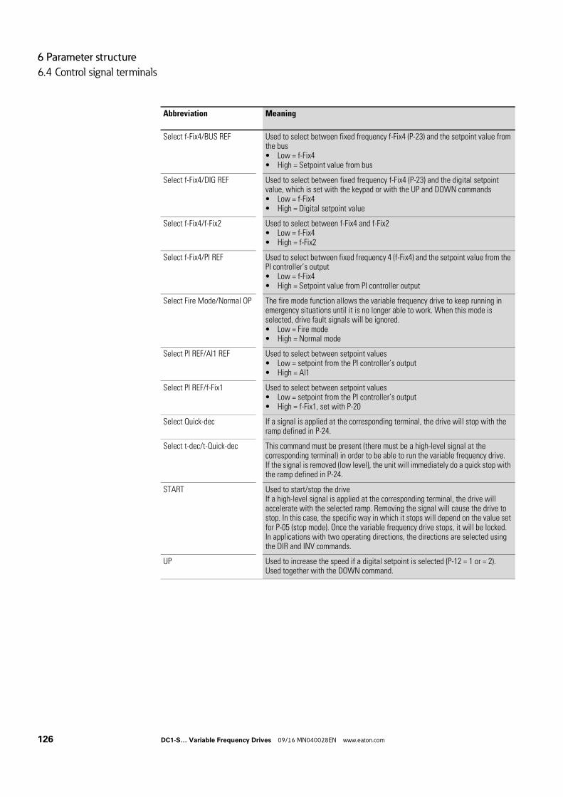
6 Parameter structure
6.4 Control signal terminals
Select f-Fix4/BUS REF Used to select between fixed frequency f-Fix4 (P-23) and the setpoint value from the bus• Low = f-Fix4• High = Setpoint value from bus
Select f-Fix4/DIG REF Used to select between fixed frequency f-Fix4 (P-23) and the digital setpoint value, which is set with the keypad or with the UP and DOWN commands• Low = f-Fix4• High = Digital setpoint value
Select f-Fix4/f-Fix2 Used to select between f-Fix4 and f-Fix2• Low = f-Fix4• High = f-Fix2
Select f-Fix4/PI REF Used to select between fixed frequency 4 (f-Fix4) and the setpoint value from the PI controller’s output• Low = f-Fix4• High = Setpoint value from PI controller output
Select Fire Mode/Normal OP The fire mode function allows the variable frequency drive to keep running in emergency situations until it is no longer able to work. When this mode is selected, drive fault signals will be ignored.• Low = Fire mode• High = Normal mode
Select PI REF/AI1 REF Used to select between setpoint values• Low = setpoint from the PI controller’s output• High = AI1
Select PI REF/f-Fix1 Used to select between setpoint values• Low = setpoint from the PI controller’s output• High = f-Fix1, set with P-20
Select Quick-dec If a signal is applied at the corresponding terminal, the drive will stop with the ramp defined in P-24.
Select t-dec/t-Quick-dec This command must be present (there must be a high-level signal at the corresponding terminal) in order to be able to run the variable frequency drive.If the signal is removed (low level), the unit will immediately do a quick stop with the ramp defined in P-24.
START Used to start/stop the driveIf a high-level signal is applied at the corresponding terminal, the drive will accelerate with the selected ramp. Removing the signal will cause the drive to stop. In this case, the specific way in which it stops will depend on the value set for P-05 (stop mode). Once the variable frequency drive stops, it will be locked.In applications with two operating directions, the directions are selected using the DIR and INV commands.
UP Used to increase the speed if a digital setpoint is selected (P-12 = 1 or = 2).Used together with the DOWN command.
Abbreviation Meaning
126 DC1-S… Variable Frequency Drives 09/16 MN040028EN www.eaton.com
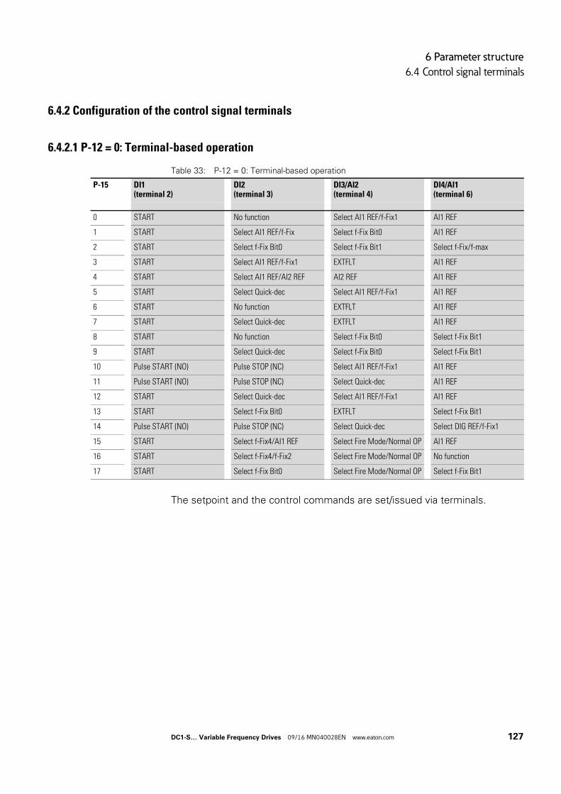
6 Parameter structure
6.4 Control signal terminals
6.4.2 Configuration of the control signal terminals
6.4.2.1 P-12 = 0: Terminal-based operation
Table 33: P-12 = 0: Terminal-based operation
The setpoint and the control commands are set/issued via terminals.
P-15 DI1(terminal 2)
DI2(terminal 3)
DI3/AI2(terminal 4)
DI4/AI1(terminal 6)
0 START No function Select AI1 REF/f-Fix1 AI1 REF
1 START Select AI1 REF/f-Fix Select f-Fix Bit0 AI1 REF
2 START Select f-Fix Bit0 Select f-Fix Bit1 Select f-Fix/f-max
3 START Select AI1 REF/f-Fix1 EXTFLT AI1 REF
4 START Select AI1 REF/AI2 REF AI2 REF AI1 REF
5 START Select Quick‐dec Select AI1 REF/f-Fix1 AI1 REF
6 START No function EXTFLT AI1 REF
7 START Select Quick‐dec EXTFLT AI1 REF
8 START No function Select f-Fix Bit0 Select f-Fix Bit1
9 START Select Quick‐dec Select f-Fix Bit0 Select f-Fix Bit1
10 Pulse START (NO) Pulse STOP (NC) Select AI1 REF/f-Fix1 AI1 REF
11 Pulse START (NO) Pulse STOP (NC) Select Quick‐dec AI1 REF
12 START Select Quick‐dec Select AI1 REF/f-Fix1 AI1 REF
13 START Select f-Fix Bit0 EXTFLT Select f-Fix Bit1
14 Pulse START (NO) Pulse STOP (NC) Select Quick‐dec Select DIG REF/f-Fix1
15 START Select f-Fix4/AI1 REF Select Fire Mode/Normal OP AI1 REF
16 START Select f-Fix4/f-Fix2 Select Fire Mode/Normal OP No function
17 START Select f-Fix Bit0 Select Fire Mode/Normal OP Select f-Fix Bit1
DC1-S… Variable Frequency Drives 09/16 MN040028EN www.eaton.com 127
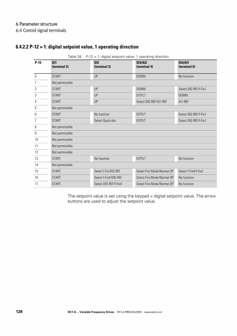
6 Parameter structure
6.4 Control signal terminals
6.4.2.2 P-12 = 1: digital setpoint value, 1 operating direction
Table 34: P-12 = 1: digital setpoint value, 1 operating direction
The setpoint value is set using the keypad = digital setpoint value. The arrow buttons are used to adjust the setpoint value.
P-15 DI1(terminal 2)
DI2(terminal 3)
DI3/AI2(terminal 4)
DI4/AI1(terminal 6)
0 START UP DOWN No function
1 Not permissible
2 START UP DOWN Select DIG REF/f-Fix1
3 START UP EXTFLT DOWN
4 START UP Select DIG REF/AI1 REF AI1 REF
5 Not permissible
6 START No function EXTFLT Select DIG REF/f-Fix1
7 START Select Quick‐dec EXTFLT Select DIG REF/f-Fix1
8 Not permissible
9 Not permissible
10 Not permissible
11 Not permissible
12 Not permissible
13 START No function EXTFLT No function
14 Not permissible
15 START Select f-Fix/DIG REF Select Fire Mode/Normal OP Select f-Fix4/f-Fix2
16 START Select f-Fix4/DIG REF Select Fire Mode/Normal OP No function
17 START Select DIG REF/f-Fix4 Select Fire Mode/Normal OP No function
128 DC1-S… Variable Frequency Drives 09/16 MN040028EN www.eaton.com
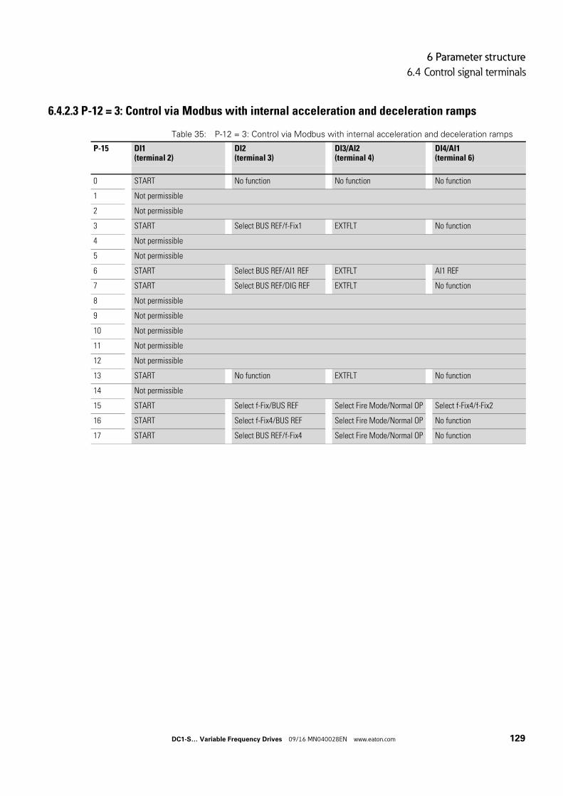
6 Parameter structure
6.4 Control signal terminals
6.4.2.3 P-12 = 3: Control via Modbus with internal acceleration and deceleration ramps
Table 35: P-12 = 3: Control via Modbus with internal acceleration and deceleration ramps
P-15 DI1(terminal 2)
DI2(terminal 3)
DI3/AI2(terminal 4)
DI4/AI1(terminal 6)
0 START No function No function No function
1 Not permissible
2 Not permissible
3 START Select BUS REF/f-Fix1 EXTFLT No function
4 Not permissible
5 Not permissible
6 START Select BUS REF/AI1 REF EXTFLT AI1 REF
7 START Select BUS REF/DIG REF EXTFLT No function
8 Not permissible
9 Not permissible
10 Not permissible
11 Not permissible
12 Not permissible
13 START No function EXTFLT No function
14 Not permissible
15 START Select f-Fix/BUS REF Select Fire Mode/Normal OP Select f-Fix4/f-Fix2
16 START Select f-Fix4/BUS REF Select Fire Mode/Normal OP No function
17 START Select BUS REF/f-Fix4 Select Fire Mode/Normal OP No function
DC1-S… Variable Frequency Drives 09/16 MN040028EN www.eaton.com 129
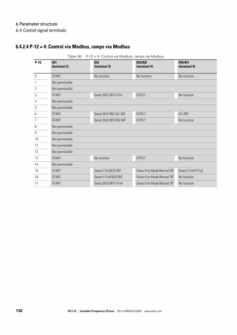
6 Parameter structure
6.4 Control signal terminals
6.4.2.4 P-12 = 4: Control via Modbus, ramps via Modbus
Table 36: P-12 = 4: Control via Modbus, ramps via Modbus
P-15 DI1(terminal 2)
DI2(terminal 3)
DI3/AI2(terminal 4)
DI4/AI1(terminal 6)
0 START No function No function No function
1 Not permissible
2 Not permissible
3 START Select BUS REF/f-Fix1 EXTFLT No function
4 Not permissible
5 Not permissible
6 START Select BUS REF/AI1 REF EXTFLT AI1 REF
7 START Select BUS REF/DIG REF EXTFLT No function
8 Not permissible
9 Not permissible
10 Not permissible
11 Not permissible
12 Not permissible
13 START No function EXTFLT No function
14 Not permissible
15 START Select f-Fix/BUS REF Select Fire Mode/Normal OP Select f-Fix4/f-Fix2
16 START Select f-Fix4/BUS REF Select Fire Mode/Normal OP No function
17 START Select BUS REF/f-Fix4 Select Fire Mode/Normal OP No function
130 DC1-S… Variable Frequency Drives 09/16 MN040028EN www.eaton.com
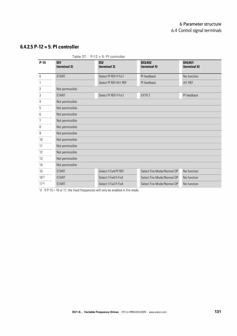
6 Parameter structure
6.4 Control signal terminals
6.4.2.5 P-12 = 5: PI controller
Table 37: P-12 = 5: PI controller
P-15 DI1(terminal 2)
DI2(terminal 3)
DI3/AI2(terminal 4)
DI4/AI1(terminal 6)
0 START Select PI REF/f-Fix1 PI feedback No function
1 Select PI REF/AI1 REF PI feedback AI1 REF
2 Not permissible
3 START Select PI REF/f-Fix1 EXTFLT PI feedback
4 Not permissible
5 Not permissible
6 Not permissible
7 Not permissible
8 Not permissible
9 Not permissible
10 Not permissible
11 Not permissible
12 Not permissible
13 Not permissible
14 Not permissible
15 START Select f-Fix4/PI REF Select Fire Mode/Normal OP No function
161) START Select f-Fix4/f-Fix2 Select Fire Mode/Normal OP No function
171) START Select f-Fix2/f-Fix4 Select Fire Mode/Normal OP No function
1) If P-15 = 16 or 17, the fixed frequencies will only be enabled in fire mode.
DC1-S… Variable Frequency Drives 09/16 MN040028EN www.eaton.com 131
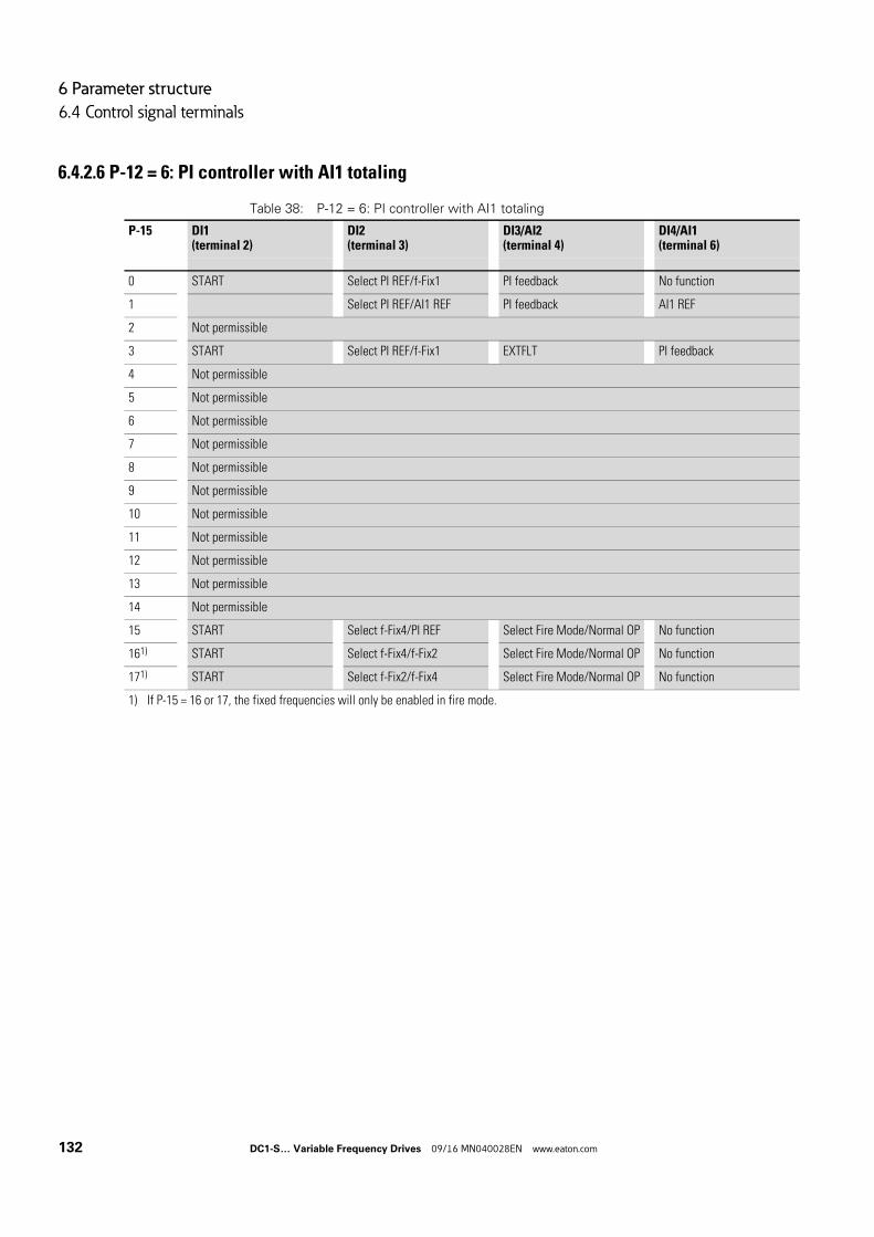
6 Parameter structure
6.4 Control signal terminals
6.4.2.6 P-12 = 6: PI controller with AI1 totaling
Table 38: P-12 = 6: PI controller with AI1 totaling
P-15 DI1(terminal 2)
DI2(terminal 3)
DI3/AI2(terminal 4)
DI4/AI1(terminal 6)
0 START Select PI REF/f-Fix1 PI feedback No function
1 Select PI REF/AI1 REF PI feedback AI1 REF
2 Not permissible
3 START Select PI REF/f-Fix1 EXTFLT PI feedback
4 Not permissible
5 Not permissible
6 Not permissible
7 Not permissible
8 Not permissible
9 Not permissible
10 Not permissible
11 Not permissible
12 Not permissible
13 Not permissible
14 Not permissible
15 START Select f-Fix4/PI REF Select Fire Mode/Normal OP No function
161) START Select f-Fix4/f-Fix2 Select Fire Mode/Normal OP No function
171) START Select f-Fix2/f-Fix4 Select Fire Mode/Normal OP No function
1) If P-15 = 16 or 17, the fixed frequencies will only be enabled in fire mode.
132 DC1-S… Variable Frequency Drives 09/16 MN040028EN www.eaton.com
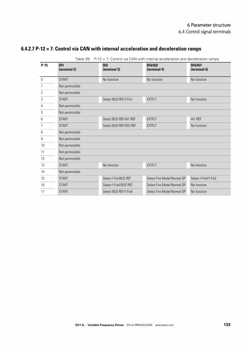
6 Parameter structure
6.4 Control signal terminals
6.4.2.7 P-12 = 7: Control via CAN with internal acceleration and deceleration ramps
Table 39: P-12 = 7: Control via CAN with internal acceleration and deceleration ramps
P-15 DI1(terminal 2)
DI2(terminal 3)
DI3/AI2(terminal 4)
DI4/AI1(terminal 6)
0 START No function No function No function
1 Not permissible
2 Not permissible
3 START Select BUS REF/f-Fix1 EXTFLT No function
4 Not permissible
5 Not permissible
6 START Select BUS REF/AI1 REF EXTFLT AI1 REF
7 START Select BUS REF/DIG REF EXTFLT No function
8 Not permissible
9 Not permissible
10 Not permissible
11 Not permissible
12 Not permissible
13 START No function EXTFLT No function
14 Not permissible
15 START Select f-Fix/BUS REF Select Fire Mode/Normal OP Select f-Fix4/f-Fix2
16 START Select f-Fix4/BUS REF Select Fire Mode/Normal OP No function
17 START Select BUS REF/f-Fix4 Select Fire Mode/Normal OP No function
DC1-S… Variable Frequency Drives 09/16 MN040028EN www.eaton.com 133
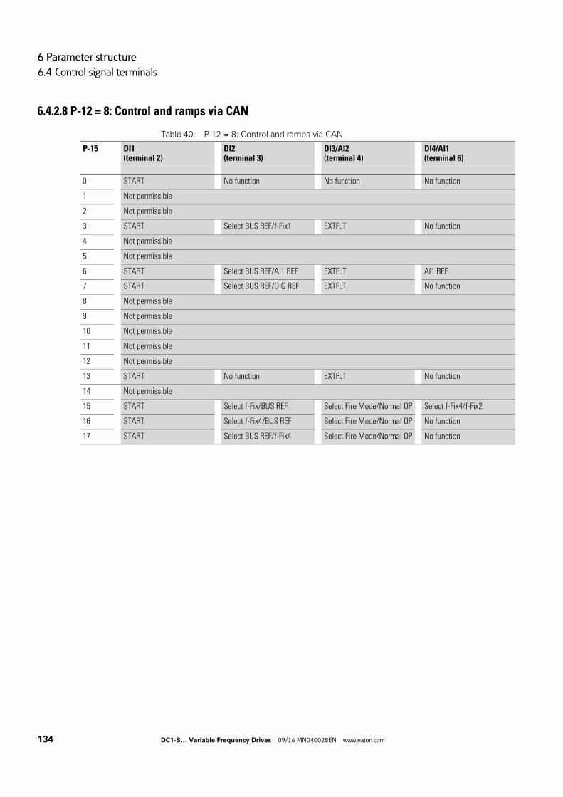
6 Parameter structure
6.4 Control signal terminals
6.4.2.8 P-12 = 8: Control and ramps via CAN
Table 40: P-12 = 8: Control and ramps via CAN
P-15 DI1(terminal 2)
DI2(terminal 3)
DI3/AI2(terminal 4)
DI4/AI1(terminal 6)
0 START No function No function No function
1 Not permissible
2 Not permissible
3 START Select BUS REF/f-Fix1 EXTFLT No function
4 Not permissible
5 Not permissible
6 START Select BUS REF/AI1 REF EXTFLT AI1 REF
7 START Select BUS REF/DIG REF EXTFLT No function
8 Not permissible
9 Not permissible
10 Not permissible
11 Not permissible
12 Not permissible
13 START No function EXTFLT No function
14 Not permissible
15 START Select f-Fix/BUS REF Select Fire Mode/Normal OP Select f-Fix4/f-Fix2
16 START Select f-Fix4/BUS REF Select Fire Mode/Normal OP No function
17 START Select BUS REF/f-Fix4 Select Fire Mode/Normal OP No function
134 DC1-S… Variable Frequency Drives 09/16 MN040028EN www.eaton.com
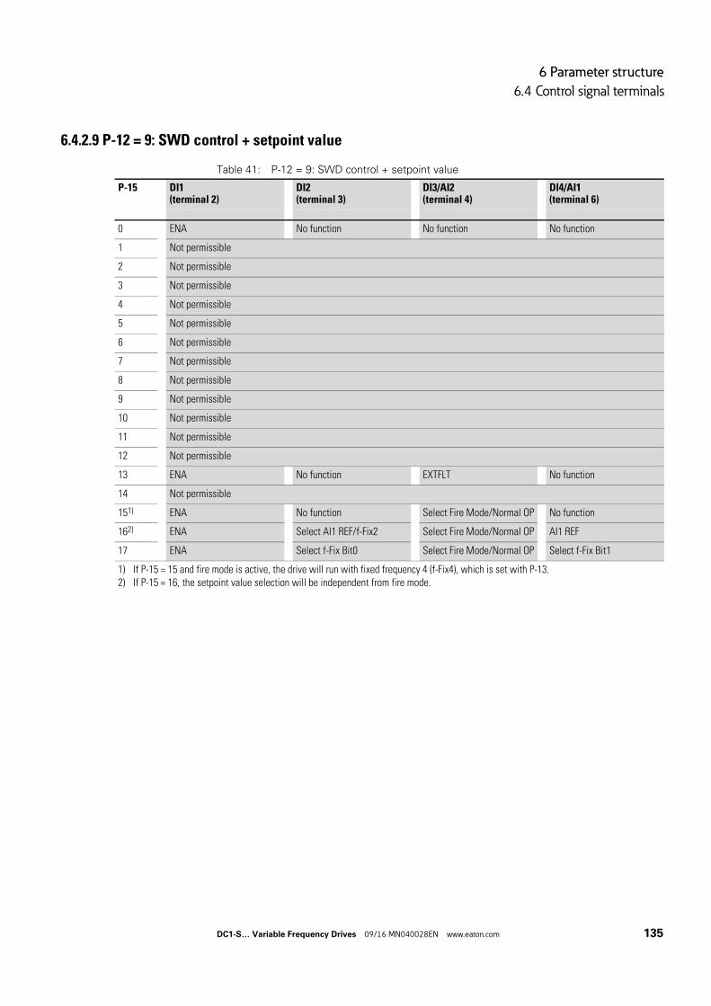
6 Parameter structure
6.4 Control signal terminals
6.4.2.9 P-12 = 9: SWD control + setpoint value
Table 41: P-12 = 9: SWD control + setpoint value
P-15 DI1(terminal 2)
DI2(terminal 3)
DI3/AI2(terminal 4)
DI4/AI1(terminal 6)
0 ENA No function No function No function
1 Not permissible
2 Not permissible
3 Not permissible
4 Not permissible
5 Not permissible
6 Not permissible
7 Not permissible
8 Not permissible
9 Not permissible
10 Not permissible
11 Not permissible
12 Not permissible
13 ENA No function EXTFLT No function
14 Not permissible
151) ENA No function Select Fire Mode/Normal OP No function
162) ENA Select AI1 REF/f-Fix2 Select Fire Mode/Normal OP AI1 REF
17 ENA Select f-Fix Bit0 Select Fire Mode/Normal OP Select f-Fix Bit1
1) If P-15 = 15 and fire mode is active, the drive will run with fixed frequency 4 (f-Fix4), which is set with P-13.2) If P-15 = 16, the setpoint value selection will be independent from fire mode.
DC1-S… Variable Frequency Drives 09/16 MN040028EN www.eaton.com 135
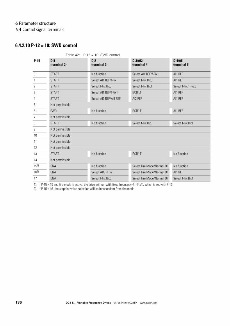
6 Parameter structure
6.4 Control signal terminals
6.4.2.10 P-12 = 10: SWD control
Table 42: P-12 = 10: SWD control
P-15 DI1(terminal 2)
DI2(terminal 3)
DI3/AI2(terminal 4)
DI4/AI1(terminal 6)
0 START No function Select AI1 REF/f-Fix1 AI1 REF
1 START Select AI1 REF/f-Fix Select f-Fix Bit0 AI1 REF
2 START Select f-Fix Bit0 Select f-Fix Bit1 Select f-Fix/f-max
3 START Select AI1 REF/f-Fix1 EXTFLT AI1 REF
4 START Select AI2 REF/AI1 REF AI2 REF AI1 REF
5 Not permissible
6 FWD No function EXTFLT AI1 REF
7 Not permissible
8 START No function Select f-Fix Bit0 Select f-Fix Bit1
9 Not permissible
10 Not permissible
11 Not permissible
12 Not permissible
13 START No function EXTFLT No function
14 Not permissible
151) ENA No function Select Fire Mode/Normal OP No function
162) ENA Select AI1/f-Fix2 Select Fire Mode/Normal OP AI1 REF
17 ENA Select f-Fix Bit0 Select Fire Mode/Normal OP Select f-Fix Bit1
1) If P-15 = 15 and fire mode is active, the drive will run with fixed frequency 4 (f-Fix4), which is set with P-13.2) If P-15 = 16, the setpoint value selection will be independent from fire mode.
136 DC1-S… Variable Frequency Drives 09/16 MN040028EN www.eaton.com
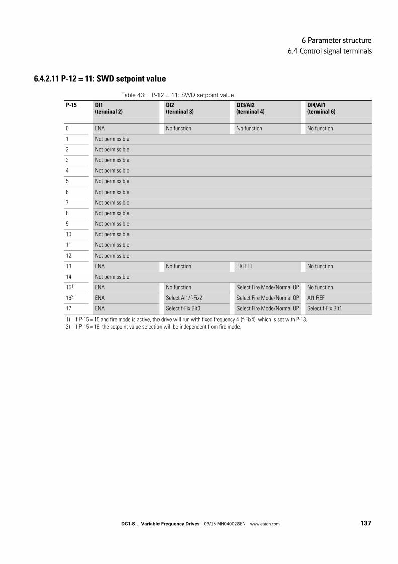
6 Parameter structure
6.4 Control signal terminals
6.4.2.11 P-12 = 11: SWD setpoint value
Table 43: P-12 = 11: SWD setpoint value
P-15 DI1(terminal 2)
DI2(terminal 3)
DI3/AI2(terminal 4)
DI4/AI1(terminal 6)
0 ENA No function No function No function
1 Not permissible
2 Not permissible
3 Not permissible
4 Not permissible
5 Not permissible
6 Not permissible
7 Not permissible
8 Not permissible
9 Not permissible
10 Not permissible
11 Not permissible
12 Not permissible
13 ENA No function EXTFLT No function
14 Not permissible
151) ENA No function Select Fire Mode/Normal OP No function
162) ENA Select AI1/f-Fix2 Select Fire Mode/Normal OP AI1 REF
17 ENA Select f-Fix Bit0 Select Fire Mode/Normal OP Select f-Fix Bit1
1) If P-15 = 15 and fire mode is active, the drive will run with fixed frequency 4 (f-Fix4), which is set with P-13.2) If P-15 = 16, the setpoint value selection will be independent from fire mode.
DC1-S… Variable Frequency Drives 09/16 MN040028EN www.eaton.com 137
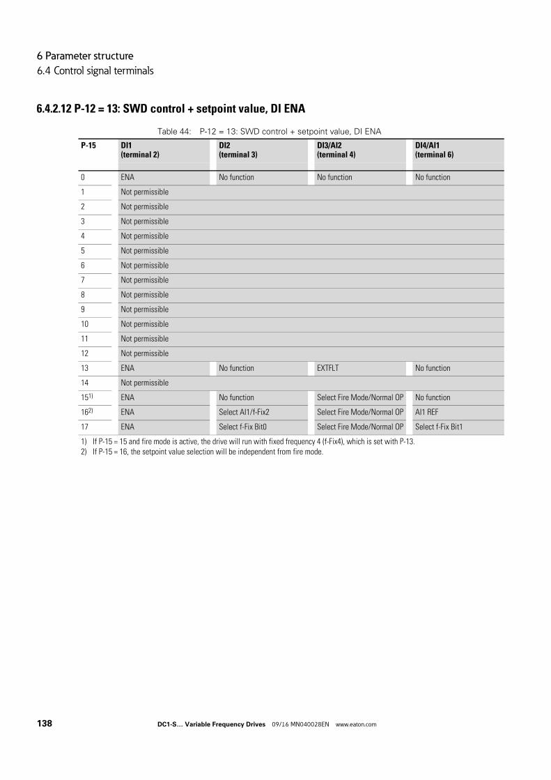
6 Parameter structure
6.4 Control signal terminals
6.4.2.12 P-12 = 13: SWD control + setpoint value, DI ENA
Table 44: P-12 = 13: SWD control + setpoint value, DI ENA
P-15 DI1(terminal 2)
DI2(terminal 3)
DI3/AI2(terminal 4)
DI4/AI1(terminal 6)
0 ENA No function No function No function
1 Not permissible
2 Not permissible
3 Not permissible
4 Not permissible
5 Not permissible
6 Not permissible
7 Not permissible
8 Not permissible
9 Not permissible
10 Not permissible
11 Not permissible
12 Not permissible
13 ENA No function EXTFLT No function
14 Not permissible
151) ENA No function Select Fire Mode/Normal OP No function
162) ENA Select AI1/f-Fix2 Select Fire Mode/Normal OP AI1 REF
17 ENA Select f-Fix Bit0 Select Fire Mode/Normal OP Select f-Fix Bit1
1) If P-15 = 15 and fire mode is active, the drive will run with fixed frequency 4 (f-Fix4), which is set with P-13.2) If P-15 = 16, the setpoint value selection will be independent from fire mode.
138 DC1-S… Variable Frequency Drives 09/16 MN040028EN www.eaton.com
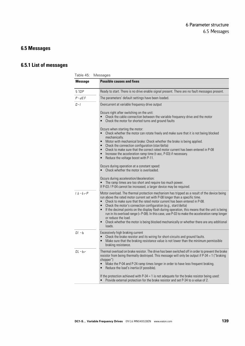
6 Parameter structure
6.5 Messages
6.5 Messages
6.5.1 List of messages
Table 45: Messages
Message Possible causes and fixes
STOP Ready to start. There is no drive enable signal present. There are no fault messages present.
P-dEf The parameters’ default settings have been loaded.
O-I Overcurrent at variable frequency drive output
Occurs right after switching on the unit:• Check the cable connection between the variable frequency drive and the motor• Check the motor for shorted turns and ground faults
Occurs when starting the motor:• Check whether the motor can rotate freely and make sure that it is not being blocked
mechanically.• Motor with mechanical brake: Check whether the brake is being applied.• Check the connection configuration (star/delta)• Check to make sure that the correct rated motor current has been entered in P-08• Increase the acceleration ramp time (t-acc, P-03) if necessary.• Reduce the voltage boost with P-11.
Occurs during operation at a constant speed:• Check whether the motor is overloaded.
Occurs during acceleration/deceleration:• The ramp times are too short and require too much power.If P-03 / P-04 cannot be increased, a larger device may be required.
I.t-trP Motor overload. The thermal protection mechanism has tripped as a result of the device being run above the rated motor current set with P-08 longer than a specific time.• Check to make sure that the rated motor current has been entered in P-08.• Check the motor’s connection configuration (e.g., start/delta)• If the decimal points on the display flash during operation, this means that the unit is being
run in its overload range (> P-08). In this case, use P-03 to make the acceleration ramp longer or reduce the load.
• Check whether the motor is being blocked mechanically or whether there are any additional loads.
OI-b Excessively high braking current• Check the brake resistor and its wiring for short-circuits and ground faults.• Make sure that the braking resistance value is not lower than the minimum permissible
braking resistance.
OL-br Thermal overload on brake resistor. The drive has been switched off in order to prevent the brake resistor from being thermally destroyed. This message will only be output if P-34 = 1 (“braking chopper”)• Make the P-04 and P-24 ramp times longer in order to have less frequent braking.• Reduce the load’s inertia (if possible).
If the protection achieved with P-34 = 1 is not adequate for the brake resistor being used:• Provide external protection for the brake resistor and set P-34 to a value of 2.
DC1-S… Variable Frequency Drives 09/16 MN040028EN www.eaton.com 139
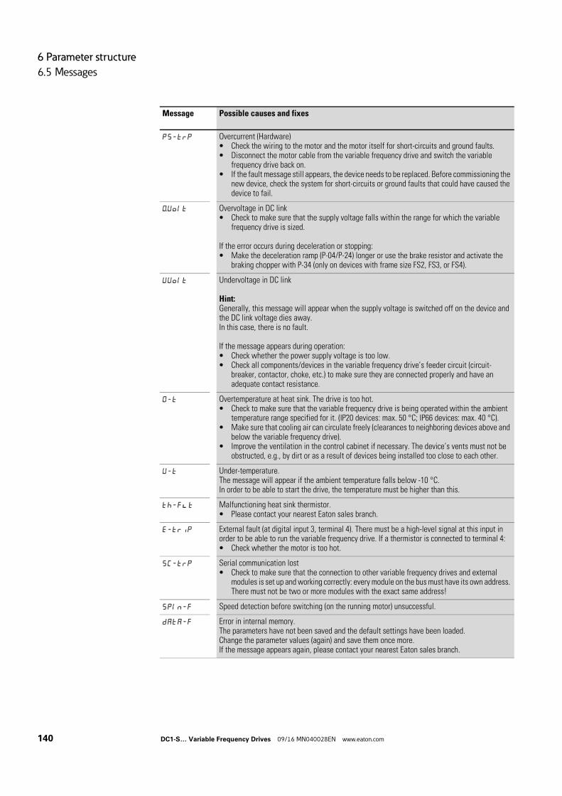
6 Parameter structure
6.5 Messages
PS-trp Overcurrent (Hardware)• Check the wiring to the motor and the motor itself for short-circuits and ground faults.• Disconnect the motor cable from the variable frequency drive and switch the variable
frequency drive back on.• If the fault message still appears, the device needs to be replaced. Before commissioning the
new device, check the system for short-circuits or ground faults that could have caused the device to fail.
O.Volt Overvoltage in DC link• Check to make sure that the supply voltage falls within the range for which the variable
frequency drive is sized.
If the error occurs during deceleration or stopping:• Make the deceleration ramp (P-04/P-24) longer or use the brake resistor and activate the
braking chopper with P-34 (only on devices with frame size FS2, FS3, or FS4).
VVolt Undervoltage in DC link
Hint:Generally, this message will appear when the supply voltage is switched off on the device and the DC link voltage dies away.In this case, there is no fault.
If the message appears during operation:• Check whether the power supply voltage is too low.• Check all components/devices in the variable frequency drive’s feeder circuit (circuit-
breaker, contactor, choke, etc.) to make sure they are connected properly and have an adequate contact resistance.
O-t Overtemperature at heat sink. The drive is too hot.• Check to make sure that the variable frequency drive is being operated within the ambient
temperature range specified for it. (IP20 devices: max. 50 °C; IP66 devices: max. 40 °C).• Make sure that cooling air can circulate freely (clearances to neighboring devices above and
below the variable frequency drive).• Improve the ventilation in the control cabinet if necessary. The device’s vents must not be
obstructed, e.g., by dirt or as a result of devices being installed too close to each other.
V-t Under-temperature.The message will appear if the ambient temperature falls below -10 °C.In order to be able to start the drive, the temperature must be higher than this.
th-f(t Malfunctioning heat sink thermistor.• Please contact your nearest Eaton sales branch.
E-trip External fault (at digital input 3, terminal 4). There must be a high-level signal at this input in order to be able to run the variable frequency drive. If a thermistor is connected to terminal 4:• Check whether the motor is too hot.
SC-trp Serial communication lost• Check to make sure that the connection to other variable frequency drives and external
modules is set up and working correctly: every module on the bus must have its own address. There must not be two or more modules with the exact same address!
SPIn-F Speed detection before switching (on the running motor) unsuccessful.
dAtA-F Error in internal memory.The parameters have not been saved and the default settings have been loaded.Change the parameter values (again) and save them once more.If the message appears again, please contact your nearest Eaton sales branch.
Message Possible causes and fixes
140 DC1-S… Variable Frequency Drives 09/16 MN040028EN www.eaton.com
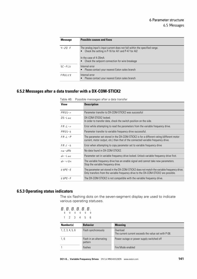
6 Parameter structure
6.5 Messages
6.5.2 Messages after a data transfer with a DX-COM-STICK2
Table 46: Possible messages after a data transfer
6.5.3 Operating status indicatorsThe six flashing dots on the seven-segment display are used to indicate various operating statuses.
4-20 F The analog input’s input current does not fall within the specified range.• Check the setting in P-16 for AI1 and P-47 for AI2
In the case of 4-20mA:• Check the setpoint connection for wire breakage
SC-FLt Internal error• Please contact your nearest Eaton sales branch
FAVLty Internal error• Please contact your nearest Eaton sales branch
Message Possible causes and fixes
View Description
PASS-r Parameter transfer to DX-COM-STICK2 was successful
OS-Loc DX-COM-STICK2 locked.In order to transfer data, check the switch position on the side.
FAiL-r Error while attempting to read the parameters from the variable frequency drive.
PASS-t Parameter transfer to variable frequency drive successful.
FAiL-P The parameter set stored in the DX-COM-STICK2 is for a different rating (different motor current, motor output, etc.) than that of the connected variable frequency drive.
Fail-t Error when attempting to copy parameter set to variable frequency drive
no-dAt No data found in DX-COM-STICK2.
dr-Loc Parameter set in variable frequency drive locked. Unlock variable frequency drive first.
dr-rVn The variable frequency drive has an enable signal and cannot take new parameters.Stop the variable frequency drive.
tyPE-E The parameter set stored in the DX-COM-STICK2 does not match the variable frequency drive.Only transfers from the variable frequency drive to the DX-COM-STICK2 are possible.
tyPE-F The DX-COM-STICK2 is not compatible with the variable frequency drive.
8 . 8 . 8 . 8 . 8 . 8 .↓ ↓ ↓ ↓ ↓ ↓
1 2 3 4 5 6
Number(s) Behavior Meaning
1, 2, 3, 4, 5, 6 Flash synchronously OverloadThe current current exceeds the value set with P-08.
1, 6 Flash in an alternating pattern
Power outage or power supply switched off
1 flashes Fire Mode enabled
DC1-S… Variable Frequency Drives 09/16 MN040028EN www.eaton.com 141
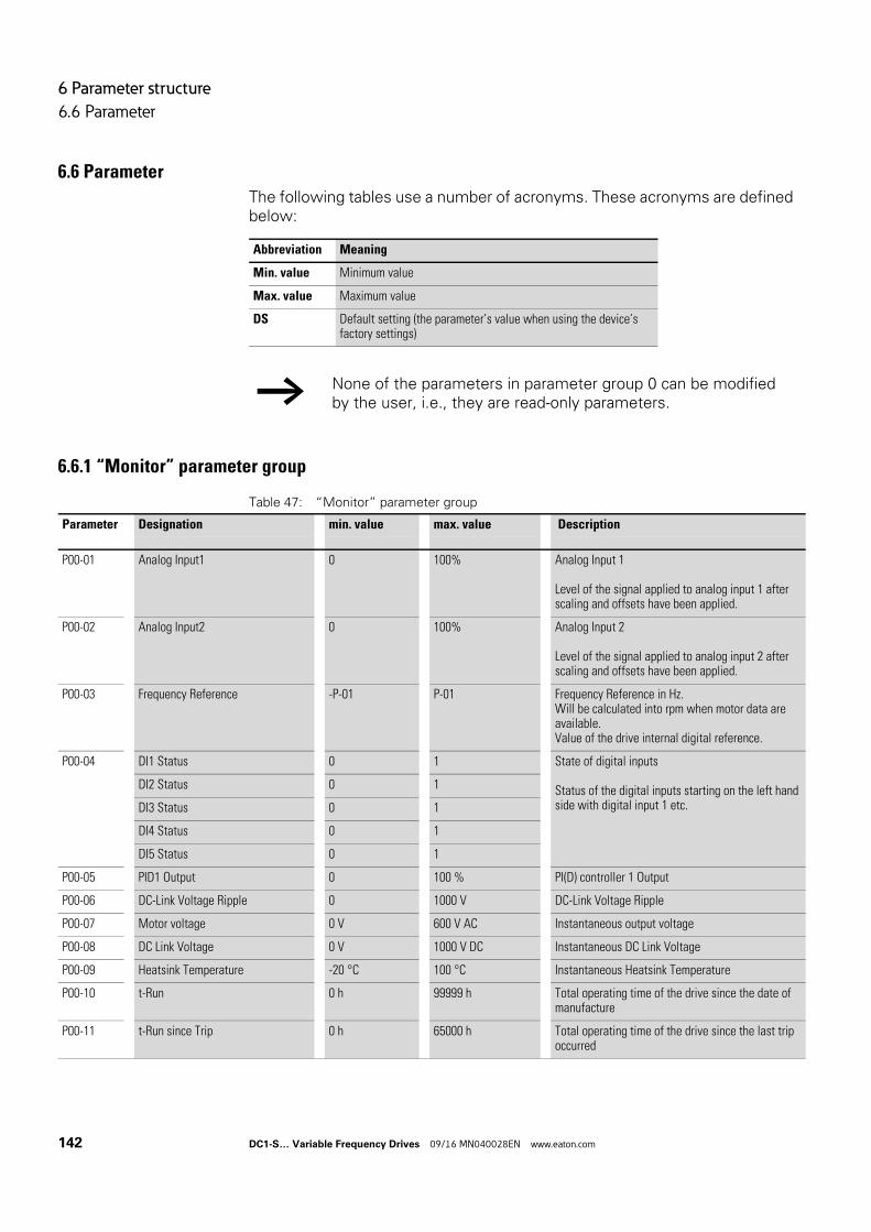
6 Parameter structure
6.6 Parameter
6.6 Parameter
The following tables use a number of acronyms. These acronyms are defined below:
6.6.1 “Monitor” parameter group
Table 47: “Monitor” parameter group
Abbreviation Meaning
Min. value Minimum value
Max. value Maximum value
DS Default setting (the parameter’s value when using the device’s factory settings)
→ None of the parameters in parameter group 0 can be modified by the user, i.e., they are read-only parameters.
Parameter Designation min. value max. value Description
P00-01 Analog Input1 0 100% Analog Input 1
Level of the signal applied to analog input 1 after scaling and offsets have been applied.
P00-02 Analog Input2 0 100% Analog Input 2
Level of the signal applied to analog input 2 after scaling and offsets have been applied.
P00-03 Frequency Reference -P-01 P-01 Frequency Reference in Hz.Will be calculated into rpm when motor data are available.Value of the drive internal digital reference.
P00-04 DI1 Status 0 1 State of digital inputs
Status of the digital inputs starting on the left hand side with digital input 1 etc.
DI2 Status 0 1
DI3 Status 0 1
DI4 Status 0 1
DI5 Status 0 1
P00-05 PID1 Output 0 100 % PI(D) controller 1 Output
P00-06 DC-Link Voltage Ripple 0 1000 V DC-Link Voltage Ripple
P00-07 Motor voltage 0 V 600 V AC Instantaneous output voltage
P00-08 DC Link Voltage 0 V 1000 V DC Instantaneous DC Link Voltage
P00-09 Heatsink Temperature -20 °C 100 °C Instantaneous Heatsink Temperature
P00-10 t-Run 0 h 99999 h Total operating time of the drive since the date of manufacture
P00-11 t-Run since Trip 0 h 65000 h Total operating time of the drive since the last trip occurred
142 DC1-S… Variable Frequency Drives 09/16 MN040028EN www.eaton.com
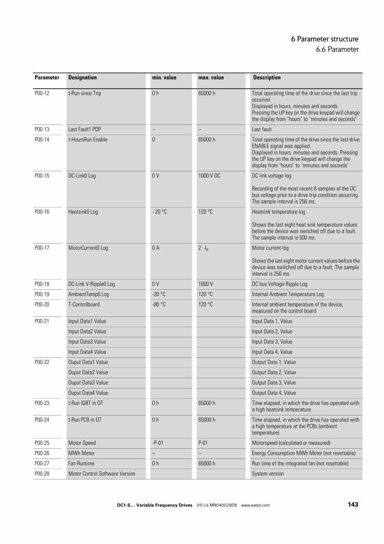
6 Parameter structure
6.6 Parameter
P00-12 t-Run since Trip 0 h 65000 h Total operating time of the drive since the last trip occurredDisplayed in hours, minutes and seconds.Pressing the UP key on the drive keypad will change the display from "hours" to "minutes and seconds"
P00-13 Last Fault1 PDP – – Last fault
P00-14 t-HoursRun Enable 0 65000 h Total operating time of the drive since the last drive ENABLE signal was applied.Displayed in hours, minutes and seconds. Pressing the UP key on the drive keypad will change the display from "hours" to "minutes and seconds"
P00-15 DC-Link0 Log 0 V 1000 V DC DC link voltage log
Recording of the most recent 8 samples of the DC bus voltage prior to a drive trip condition occurring.The sample interval is 256 ms.
P00-16 Heatsink0 Log - 20 °C 120 °C Heatsink temperature log
Shows the last eight heat sink temperature values before the device was switched off due to a fault.The sample interval is 500 ms.
P00-17 MotorCurrent0 Log 0 A 2 ∙ Ie Motor current log
Shows the last eight motor current values before the device was switched off due to a fault. The sample interval is 256 ms.
P00-18 DC-Link V-Ripple0 Log 0 V 1000 V DC bus Voltage Ripple Log
P00-19 AmbientTemp0 Log -20 °C 120 °C Internal Ambient Temperature Log
P00-20 T-Controlboard -80 °C 120 °C Internal ambient temperature of the device, measured on the control board
P00-21 Input Data1 Value Input Data 1, Value
Input Data2 Value Input Data 2, Value
Input Data3 Value Input Data 3, Value
Input Data4 Value Input Data 4, Value
P00-22 Ouput Data1 Value Output Data 1, Value
Ouput Data2 Value Output Data 2, Value
Ouput Data3 Value Output Data 3, Value
Ouput Data4 Value Output Data 4, Value
P00-23 t-Run IGBT in OT 0 h 65000 h Time elapsed, in which the drive has operated with a high heatsink temperature
P00-24 t-Run PCB in OT 0 h 65000 h Time elapsed, in which the drive has operated with a high temperature at the PCBs (ambient temperature)
P00-25 Motor Speed -P-01 P-01 Motorspeed (calculated or measured)
P00-26 MWh Meter – – Energy Consumption MWh Meter (not resettable)
P00-27 Fan Runtime 0 h 65000 h Run time of the integrated fan (not resettable)
P00-28 Motor Control Software Version System version
Parameter Designation min. value max. value Description
DC1-S… Variable Frequency Drives 09/16 MN040028EN www.eaton.com 143
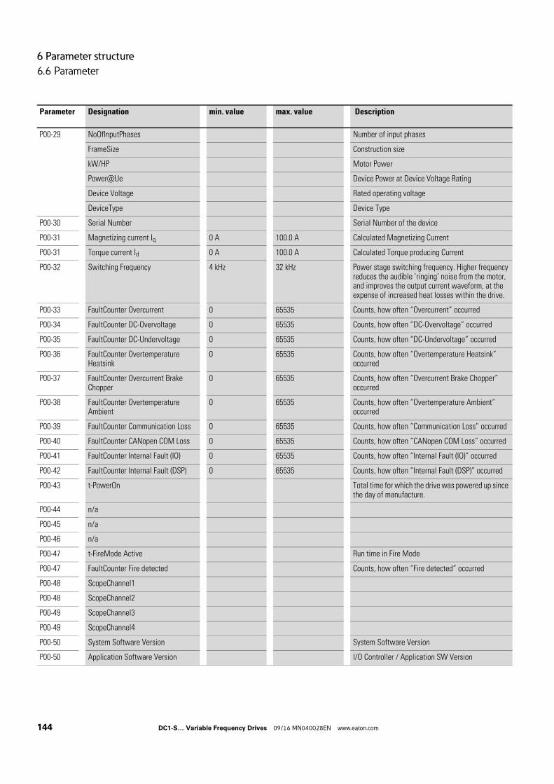
6 Parameter structure
6.6 Parameter
P00-29 NoOfInputPhases Number of input phases
FrameSize Construction size
kW/HP Motor Power
Power@Ue Device Power at Device Voltage Rating
Device Voltage Rated operating voltage
DeviceType Device Type
P00-30 Serial Number Serial Number of the device
P00-31 Magnetizing current Iq 0 A 100.0 A Calculated Magnetizing Current
P00-31 Torque current Id 0 A 100.0 A Calculated Torque producing Current
P00-32 Switching Frequency 4 kHz 32 kHz Power stage switching frequency. Higher frequency reduces the audible ’ringing’ noise from the motor, and improves the output current waveform, at the expense of increased heat losses within the drive.
P00-33 FaultCounter Overcurrent 0 65535 Counts, how often “Overcurrent” occurred
P00-34 FaultCounter DC-Overvoltage 0 65535 Counts, how often “DC-Overvoltage” occurred
P00-35 FaultCounter DC-Undervoltage 0 65535 Counts, how often “DC-Undervoltage” occurred
P00-36 FaultCounter Overtemperature Heatsink
0 65535 Counts, how often “Overtemperature Heatsink” occurred
P00-37 FaultCounter Overcurrent Brake Chopper
0 65535 Counts, how often “Overcurrent Brake Chopper” occurred
P00-38 FaultCounter Overtemperature Ambient
0 65535 Counts, how often “Overtemperature Ambient” occurred
P00-39 FaultCounter Communication Loss 0 65535 Counts, how often “Communication Loss” occurred
P00-40 FaultCounter CANopen COM Loss 0 65535 Counts, how often “CANopen COM Loss” occurred
P00-41 FaultCounter Internal Fault (IO) 0 65535 Counts, how often “Internal Fault (IO)” occurred
P00-42 FaultCounter Internal Fault (DSP) 0 65535 Counts, how often “Internal Fault (DSP)” occurred
P00-43 t-PowerOn Total time for which the drive was powered up since the day of manufacture.
P00-44 n/a
P00-45 n/a
P00-46 n/a
P00-47 t-FireMode Active Run time in Fire Mode
P00-47 FaultCounter Fire detected Counts, how often “Fire detected” occurred
P00-48 ScopeChannel1
P00-48 ScopeChannel2
P00-49 ScopeChannel3
P00-49 ScopeChannel4
P00-50 System Software Version System Software Version
P00-50 Application Software Version I/O Controller / Application SW Version
Parameter Designation min. value max. value Description
144 DC1-S… Variable Frequency Drives 09/16 MN040028EN www.eaton.com
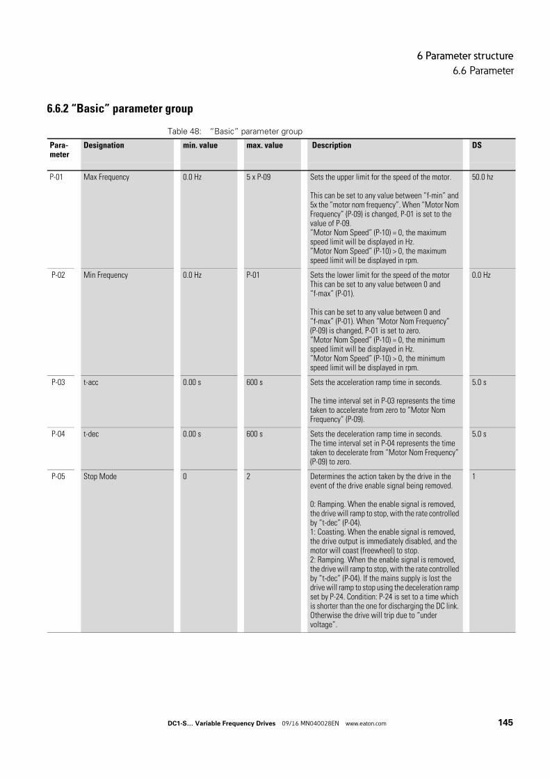
6 Parameter structure
6.6 Parameter
6.6.2 “Basic” parameter group
Table 48: “Basic” parameter group
Para-meter
Designation min. value max. value Description DS
P-01 Max Frequency 0.0 Hz 5 x P-09 Sets the upper limit for the speed of the motor.
This can be set to any value between “f-min” and 5x the “motor nom frequency”. When “Motor Nom Frequency” (P-09) is changed, P-01 is set to the value of P-09.”Motor Nom Speed” (P-10) = 0, the maximum speed limit will be displayed in Hz.”Motor Nom Speed” (P-10) > 0, the maximum speed limit will be displayed in rpm.
50.0 hz
P-02 Min Frequency 0.0 Hz P-01 Sets the lower limit for the speed of the motorThis can be set to any value between 0 and “f-max” (P-01).
This can be set to any value between 0 and “f-max” (P-01). When “Motor Nom Frequency” (P-09) is changed, P-01 is set to zero.“Motor Nom Speed” (P-10) = 0, the minimum speed limit will be displayed in Hz.”Motor Nom Speed” (P-10) > 0, the minimum speed limit will be displayed in rpm.
0.0 Hz
P-03 t-acc 0.00 s 600 s Sets the acceleration ramp time in seconds.
The time interval set in P-03 represents the time taken to accelerate from zero to “Motor Nom Frequency” (P-09).
5.0 s
P-04 t-dec 0.00 s 600 s Sets the deceleration ramp time in seconds.The time interval set in P-04 represents the time taken to decelerate from “Motor Nom Frequency” (P-09) to zero.
5.0 s
P-05 Stop Mode 0 2 Determines the action taken by the drive in the event of the drive enable signal being removed.
0: Ramping. When the enable signal is removed, the drive will ramp to stop, with the rate controlled by “t-dec” (P-04).1: Coasting. When the enable signal is removed, the drive output is immediately disabled, and the motor will coast (freewheel) to stop.2: Ramping. When the enable signal is removed, the drive will ramp to stop, with the rate controlled by “t-dec” (P-04). If the mains supply is lost the drive will ramp to stop using the deceleration ramp set by P-24. Condition: P-24 is set to a time which is shorter than the one for discharging the DC link. Otherwise the drive will trip due to “under voltage”.
1
DC1-S… Variable Frequency Drives 09/16 MN040028EN www.eaton.com 145
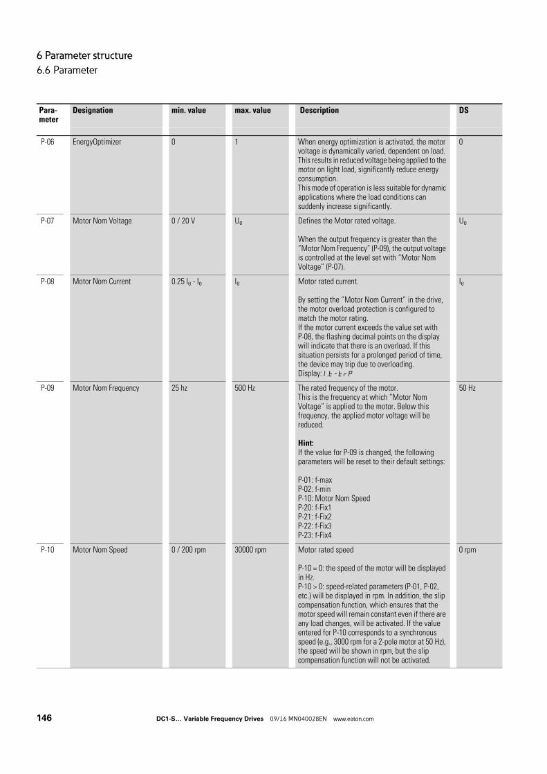
6 Parameter structure
6.6 Parameter
P-06 EnergyOptimizer 0 1 When energy optimization is activated, the motor voltage is dynamically varied, dependent on load. This results in reduced voltage being applied to the motor on light load, significantly reduce energy consumption.This mode of operation is less suitable for dynamic applications where the load conditions can suddenly increase significantly.
0
P-07 Motor Nom Voltage 0 / 20 V Ue Defines the Motor rated voltage.
When the output frequency is greater than the ”Motor Nom Frequency” (P-09), the output voltage is controlled at the level set with “Motor Nom Voltage” (P-07).
Ue
P-08 Motor Nom Current 0.25 Ie - Ie Ie Motor rated current.
By setting the ”Motor Nom Current” in the drive, the motor overload protection is configured to match the motor rating.If the motor current exceeds the value set with P-08, the flashing decimal points on the display will indicate that there is an overload. If this situation persists for a prolonged period of time, the device may trip due to overloading.Display: I.t-trP
Ie
P-09 Motor Nom Frequency 25 hz 500 Hz The rated frequency of the motor.This is the frequency at which ”Motor Nom Voltage” is applied to the motor. Below this frequency, the applied motor voltage will be reduced.
Hint:If the value for P-09 is changed, the following parameters will be reset to their default settings:
P-01: f-maxP-02: f-minP-10: Motor Nom SpeedP-20: f-Fix1P-21: f-Fix2P-22: f-Fix3P-23: f-Fix4
50 Hz
P-10 Motor Nom Speed 0 / 200 rpm 30000 rpm Motor rated speed
P-10 = 0: the speed of the motor will be displayed in Hz.P-10 > 0: speed-related parameters (P-01, P-02, etc.) will be displayed in rpm. In addition, the slip compensation function, which ensures that the motor speed will remain constant even if there are any load changes, will be activated. If the value entered for P-10 corresponds to a synchronous speed (e.g., 3000 rpm for a 2-pole motor at 50 Hz), the speed will be shown in rpm, but the slip compensation function will not be activated.
0 rpm
Para-meter
Designation min. value max. value Description DS
146 DC1-S… Variable Frequency Drives 09/16 MN040028EN www.eaton.com
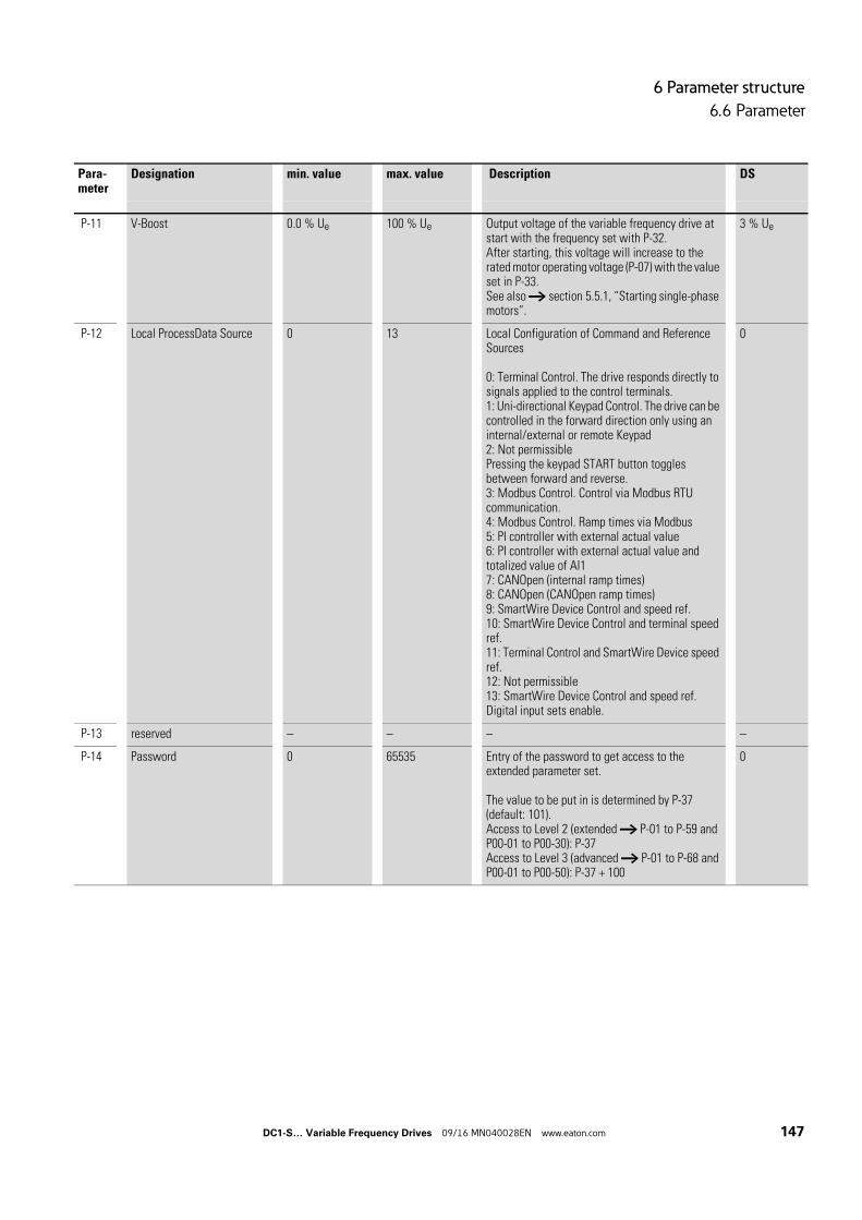
6 Parameter structure
6.6 Parameter
P-11 V-Boost 0.0 % Ue 100 % Ue Output voltage of the variable frequency drive at start with the frequency set with P-32.After starting, this voltage will increase to the rated motor operating voltage (P-07) with the value set in P-33.See also → section 5.5.1, “Starting single-phase motors”.
3 % Ue
P-12 Local ProcessData Source 0 13 Local Configuration of Command and Reference Sources
0: Terminal Control. The drive responds directly to signals applied to the control terminals.1: Uni-directional Keypad Control. The drive can be controlled in the forward direction only using an internal/external or remote Keypad2: Not permissiblePressing the keypad START button toggles between forward and reverse.3: Modbus Control. Control via Modbus RTU communication.4: Modbus Control. Ramp times via Modbus5: PI controller with external actual value6: PI controller with external actual value and totalized value of AI17: CANOpen (internal ramp times)8: CANOpen (CANOpen ramp times)9: SmartWire Device Control and speed ref.10: SmartWire Device Control and terminal speed ref.11: Terminal Control and SmartWire Device speed ref.12: Not permissible13: SmartWire Device Control and speed ref. Digital input sets enable.
0
P-13 reserved – – – –
P-14 Password 0 65535 Entry of the password to get access to the extended parameter set.
The value to be put in is determined by P-37 (default: 101).Access to Level 2 (extended → P-01 to P-59 and P00-01 to P00-30): P-37Access to Level 3 (advanced → P-01 to P-68 and P00-01 to P00-50): P-37 + 100
0
Para-meter
Designation min. value max. value Description DS
DC1-S… Variable Frequency Drives 09/16 MN040028EN www.eaton.com 147
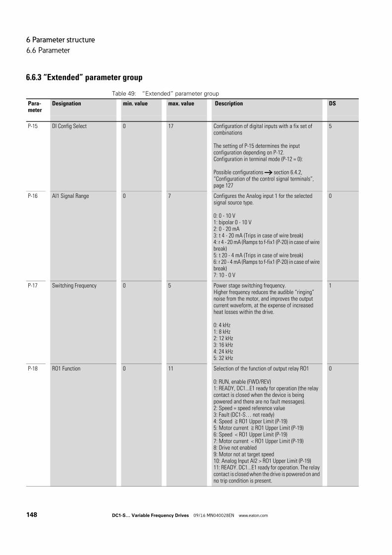
6 Parameter structure
6.6 Parameter
6.6.3 “Extended” parameter group
Table 49: “Extended” parameter group
Para-meter
Designation min. value max. value Description DS
P-15 DI Config Select 0 17 Configuration of digital inputs with a fix set of combinations
The setting of P-15 determines the input configuration depending on P-12.Configuration in terminal mode (P-12 = 0):
Possible configurations → section 6.4.2, “Configuration of the control signal terminals”, page 127
5
P-16 AI1 Signal Range 0 7 Configures the Analog input 1 for the selected signal source type.
0: 0 - 10 V1: bipolar 0 - 10 V2: 0 - 20 mA3: t 4 - 20 mA (Trips in case of wire break)4: r 4 - 20 mA (Ramps to f-fix1 (P-20) in case of wire break)5: t 20 - 4 mA (Trips in case of wire break)6: r 20 - 4 mA (Ramps to f-fix1 (P-20) in case of wire break)7: 10 - 0 V
0
P-17 Switching Frequency 0 5 Power stage switching frequency.Higher frequency reduces the audible “ringing” noise from the motor, and improves the output current waveform, at the expense of increased heat losses within the drive.
0: 4 kHz1: 8 kHz2: 12 kHz3: 16 kHz4: 24 kHz5: 32 kHz
1
P-18 RO1 Function 0 11 Selection of the function of output relay RO1
0: RUN, enable (FWD/REV)1: READY, DC1...E1 ready for operation (the relay contact is closed when the device is being powered and there are no fault messages).2: Speed = speed reference value3: Fault (DC1-S… not ready)4: Speed ≧ RO1 Upper Limit (P-19)5: Motor current ≧ RO1 Upper Limit (P-19)6: Speed < RO1 Upper Limit (P-19)7: Motor current < RO1 Upper Limit (P-19)8: Drive not enabled9: Motor not at target speed10: Analog Input AI2 > RO1 Upper Limit (P-19)11: READY. DC1...E1 ready for operation. The relay contact is closed when the drive is powered on and no trip condition is present.
0
148 DC1-S… Variable Frequency Drives 09/16 MN040028EN www.eaton.com
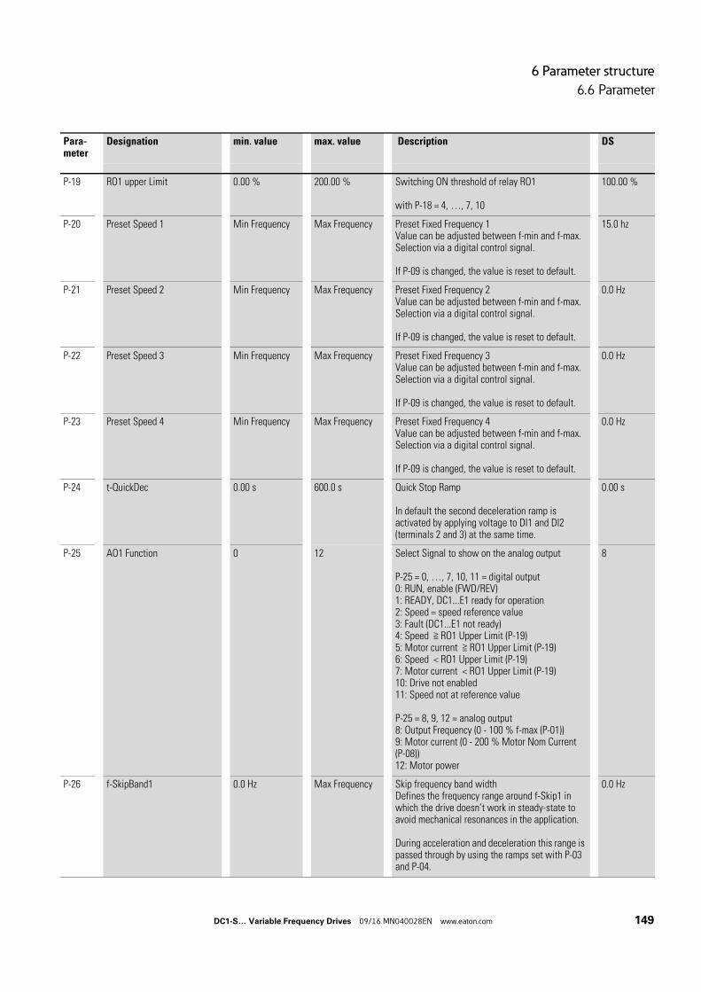
6 Parameter structure
6.6 Parameter
P-19 RO1 upper Limit 0.00 % 200.00 % Switching ON threshold of relay RO1
with P-18 = 4, …, 7, 10
100.00 %
P-20 Preset Speed 1 Min Frequency Max Frequency Preset Fixed Frequency 1Value can be adjusted between f-min and f-max. Selection via a digital control signal.
If P-09 is changed, the value is reset to default.
15.0 hz
P-21 Preset Speed 2 Min Frequency Max Frequency Preset Fixed Frequency 2Value can be adjusted between f-min and f-max. Selection via a digital control signal.
If P-09 is changed, the value is reset to default.
0.0 Hz
P-22 Preset Speed 3 Min Frequency Max Frequency Preset Fixed Frequency 3Value can be adjusted between f-min and f-max. Selection via a digital control signal.
If P-09 is changed, the value is reset to default.
0.0 Hz
P-23 Preset Speed 4 Min Frequency Max Frequency Preset Fixed Frequency 4Value can be adjusted between f-min and f-max. Selection via a digital control signal.
If P-09 is changed, the value is reset to default.
0.0 Hz
P-24 t-QuickDec 0.00 s 600.0 s Quick Stop Ramp
In default the second deceleration ramp is activated by applying voltage to DI1 and DI2 (terminals 2 and 3) at the same time.
0.00 s
P-25 AO1 Function 0 12 Select Signal to show on the analog output
P-25 = 0, …, 7, 10, 11 = digital output0: RUN, enable (FWD/REV)1: READY, DC1...E1 ready for operation2: Speed = speed reference value3: Fault (DC1...E1 not ready)4: Speed ≧ RO1 Upper Limit (P-19)5: Motor current ≧ RO1 Upper Limit (P-19)6: Speed < RO1 Upper Limit (P-19)7: Motor current < RO1 Upper Limit (P-19)10: Drive not enabled11: Speed not at reference value
P-25 = 8, 9, 12 = analog output8: Output Frequency (0 - 100 % f-max (P-01))9: Motor current (0 - 200 % Motor Nom Current (P-08))12: Motor power
8
P-26 f-SkipBand1 0.0 Hz Max Frequency Skip frequency band widthDefines the frequency range around f-Skip1 in which the drive doesn’t work in steady-state to avoid mechanical resonances in the application.
During acceleration and deceleration this range is passed through by using the ramps set with P-03 and P-04.
0.0 Hz
Para-meter
Designation min. value max. value Description DS
DC1-S… Variable Frequency Drives 09/16 MN040028EN www.eaton.com 149
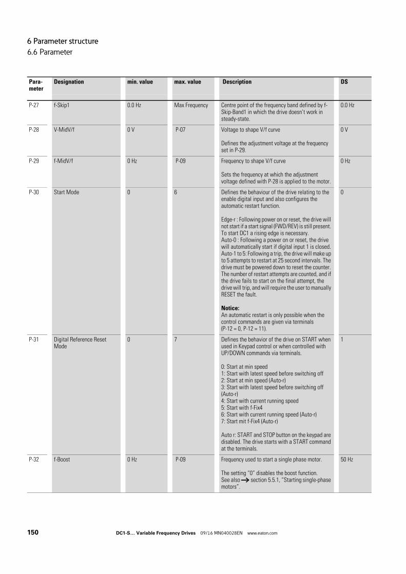
6 Parameter structure
6.6 Parameter
P-27 f-Skip1 0.0 Hz Max Frequency Centre point of the frequency band defined by f-Skip-Band1 in which the drive doesn’t work in steady-state.
0.0 Hz
P-28 V-MidV/f 0 V P-07 Voltage to shape V/f curve
Defines the adjustment voltage at the frequency set in P-29.
0 V
P-29 f-MidV/f 0 Hz P-09 Frequency to shape V/f curve
Sets the frequency at which the adjustment voltage defined with P-28 is applied to the motor.
0 Hz
P-30 Start Mode 0 6 Defines the behaviour of the drive relating to the enable digital input and also configures the automatic restart function.
Edge-r : Following power on or reset, the drive will not start if a start signal (FWD/REV) is still present. To start DC1 a rising edge is necessary.Auto-0 : Following a power on or reset, the drive will automatically start if digital input 1 is closed.Auto-1 to 5: Following a trip, the drive will make up to 5 attempts to restart at 25 second intervals. The drive must be powered down to reset the counter. The number of restart attempts are counted, and if the drive fails to start on the final attempt, the drive will trip, and will require the user to manually RESET the fault.
Notice:An automatic restart is only possible when the control commands are given via terminals (P-12 = 0, P-12 = 11).
0
P-31 Digital Reference Reset Mode
0 7 Defines the behavior of the drive on START when used in Keypad control or when controlled with UP/DOWN commands via terminals.
0: Start at min speed1: Start with latest speed before switching off2: Start at min speed (Auto-r)3: Start with latest speed before switching off (Auto-r)4: Start with current running speed5: Start with f-Fix46: Start with current running speed (Auto-r)7: Start mit f-Fix4 (Auto-r)
Auto r: START and STOP button on the keypad are disabled. The drive starts with a START command at the terminals.
1
P-32 f-Boost 0 Hz P-09 Frequency used to start a single phase motor.
The setting “0” disables the boost function.See also → section 5.5.1, “Starting single-phase motors”.
50 Hz
Para-meter
Designation min. value max. value Description DS
150 DC1-S… Variable Frequency Drives 09/16 MN040028EN www.eaton.com
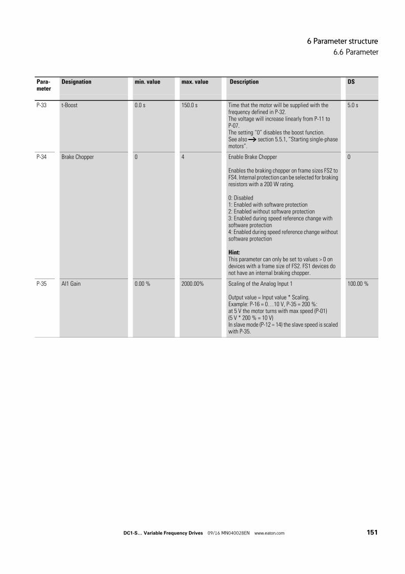
6 Parameter structure
6.6 Parameter
P-33 t-Boost 0.0 s 150.0 s Time that the motor will be supplied with the frequency defined in P-32.The voltage will increase linearly from P-11 to P-07.The setting “0” disables the boost function.See also → section 5.5.1, “Starting single-phase motors”.
5.0 s
P-34 Brake Chopper 0 4 Enable Brake Chopper
Enables the braking chopper on frame sizes FS2 to FS4. Internal protection can be selected for braking resistors with a 200 W rating.
0: Disabled1: Enabled with software protection2: Enabled without software protection3: Enabled during speed reference change with software protection4: Enabled during speed reference change without software protection
Hint:This parameter can only be set to values > 0 on devices with a frame size of FS2. FS1 devices do not have an internal braking chopper.
0
P-35 AI1 Gain 0.00 % 2000.00% Scaling of the Analog Input 1
Output value = Input value * Scaling.Example: P-16 = 0…10 V, P-35 = 200 %:at 5 V the motor turns with max speed (P-01)(5 V * 200 % = 10 V)In slave mode (P-12 = 14) the slave speed is scaled with P-35.
100.00 %
Para-meter
Designation min. value max. value Description DS
DC1-S… Variable Frequency Drives 09/16 MN040028EN www.eaton.com 151
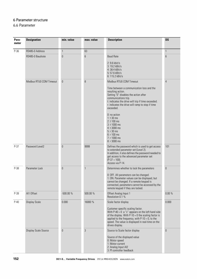
6 Parameter structure
6.6 Parameter
P-36 RS485-0 Address 1 63 1
RS485-0 Baudrate 0 6 Baud Rate
2: 9.6 kbit/s3: 19.2 kBit/s4: 38.4 kBit/s5: 57.6 kBit/s6: 115.2 kBit/s
6
Modbus RTU0 COM Timeout 0 8 Modbus RTU0 COM Timeout
Time between a communication loss and the resulting action.Setting "0” disables the action after communications trip.t: indicates the drive will trip if time exceeded.r: indicates the drive will ramp to stop if time exceeded.
0: no action1: t 30 ms2: t 100 ms3: t 1000 ms4: t 3000 ms5: r 30 ms6: r 100 ms7: r 1000 ms8: r 3000 ms
4
P-37 Password Level2 0 9999 Defines the password which is used to get access to extended parameter set (Level 2).In addition, it also defines the password needed to get access to the advanced parameter set (P-37 + 100).Access via P-14.
101
P-38 Parameter Lock 0 1 Determines whether to lock the parameters
0: OFF. All parameters can be changed.1: ON. Parameter values can be displayed, but cannot be changed. If a remote keypad is connected, parameters cannot be accessed by the remote keypad if they are locked.
0
P-39 AI1 Offset -500.00 % 500.00 % Offset Analog Input 1Resolution 0.1 %
0.00 %
P-40 Display Scale 0.000 16000 % Scale factor display
Customer specific scaling factor.With P-40 > 0 a “c” appears on the left hand side of the display. With P-10 = 0 the scaling factor is applied to the frequency, with P-10 > 0, to the speed. The value is displayed in real-time on the drives display.
0.000
Display Scale Source 0 3 Source to Scale factor display
Source of the displayed value0: Motor speed1: Motor current2: Analog Input AI23: PI controller feedback
0
Para-meter
Designation min. value max. value Description DS
152 DC1-S… Variable Frequency Drives 09/16 MN040028EN www.eaton.com
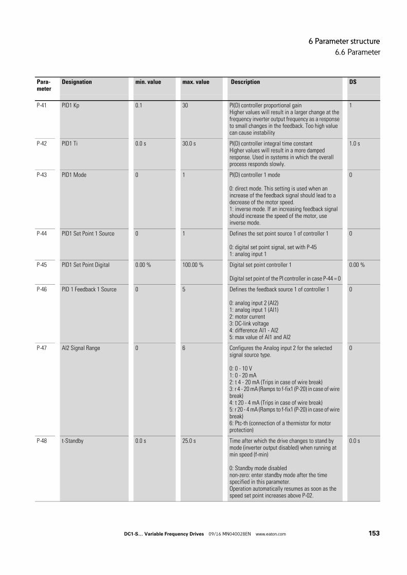
6 Parameter structure
6.6 Parameter
P-41 PID1 Kp 0.1 30 PI(D) controller proportional gainHigher values will result in a larger change at the frequency inverter output frequency as a response to small changes in the feedback. Too high value can cause instability
1
P-42 PID1 Ti 0.0 s 30.0 s PI(D) controller integral time constantHigher values will result in a more damped response. Used in systems in which the overall process responds slowly.
1.0 s
P-43 PID1 Mode 0 1 PI(D) controller 1 mode
0: direct mode. This setting is used when an increase of the feedback signal should lead to a decrease of the motor speed.1: inverse mode. If an increasing feedback signal should increase the speed of the motor, use inverse mode.
0
P-44 PID1 Set Point 1 Source 0 1 Defines the set point source 1 of controller 1
0: digital set point signal, set with P-451: analog input 1
0
P-45 PID1 Set Point Digital 0.00 % 100.00 % Digital set point controller 1
Digital set point of the PI controller in case P-44 = 0
0.00 %
P-46 PID 1 Feedback 1 Source 0 5 Defines the feedback source 1 of controller 1
0: analog input 2 (AI2)1: analog input 1 (AI1)2: motor current3: DC-link voltage4: difference AI1 - AI25: max value of AI1 and AI2
0
P-47 AI2 Signal Range 0 6 Configures the Analog input 2 for the selected signal source type.
0: 0 - 10 V1: 0 - 20 mA2: t 4 - 20 mA (Trips in case of wire break)3: r 4 - 20 mA (Ramps to f-fix1 (P-20) in case of wire break)4: t 20 - 4 mA (Trips in case of wire break)5: r 20 - 4 mA (Ramps to f-fix1 (P-20) in case of wire break)6: Ptc-th (connection of a thermistor for motor protection)
0
P-48 t-Standby 0.0 s 25.0 s Time after which the drive changes to stand by mode (inverter output disabled) when running at min speed (f-min)
0: Standby mode disablednon-zero: enter standby mode after the time specified in this parameter.Operation automatically resumes as soon as the speed set point increases above P-02.
0.0 s
Para-meter
Designation min. value max. value Description DS
DC1-S… Variable Frequency Drives 09/16 MN040028EN www.eaton.com 153
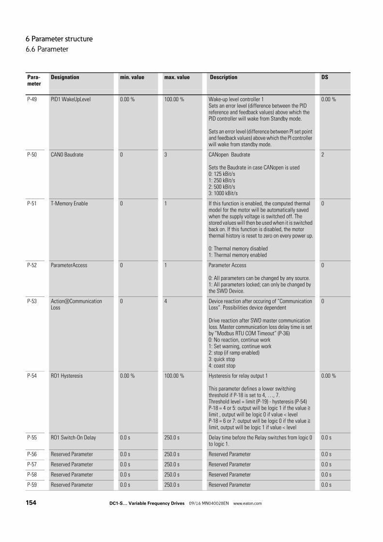
6 Parameter structure
6.6 Parameter
P-49 PID1 WakeUpLevel 0.00 % 100.00 % Wake-up level controller 1Sets an error level (difference between the PID reference and feedback values) above which the PID controller will wake from Standby mode.
Sets an error level (difference between PI set point and feedback values) above which the PI controller will wake from standby mode.
0.00 %
P-50 CAN0 Baudrate 0 3 CANopen Baudrate
Sets the Baudrate in case CANopen is used0: 125 kBit/s1: 250 kBit/s2: 500 kBit/s3: 1000 kBit/s
2
P-51 T-Memory Enable 0 1 If this function is enabled, the computed thermal model for the motor will be automatically saved when the supply voltage is switched off. The stored values will then be used when it is switched back on. If this function is disabled, the motor thermal history is reset to zero on every power up.
0: Thermal memory disabled1: Thermal memory enabled
0
P-52 ParameterAccess 0 1 Parameter Access
0: All parameters can be changed by any source.1: All parameters locked; can only be changed by the SWD Device.
0
P-53 Action@Communication Loss
0 4 Device reaction after occuring of “Communication Loss”. Possibilities device dependent
Drive reaction after SWD master communication loss. Master communication loss delay time is set by ”Modbus RTU COM Timeout” (P-36)0: No reaction, continue work1: Set warning, continue work2: stop (if ramp enabled)3: quick stop4: coast stop
0
P-54 RO1 Hysteresis 0.00 % 100.00 % Hysteresis for relay output 1
This parameter defines a lower switching threshold if P-18 is set to 4, …, 7.Threshold level = limit (P-19) - hysteresis (P-54)P-18 = 4 or 5: output will be logic 1 if the value ≧ limit , output will be logic 0 if value < levelP-18 = 6 or 7: output will be logic 0 if the value ≧ limit, output will be logic 1 if value < level
0.00 %
P-55 RO1 Switch-On Delay 0.0 s 250.0 s Delay time before the Relay switches from logic 0 to logic 1.
0.0 s
P-56 Reserved Parameter 0.0 s 250.0 s Reserved Parameter 0.0 s
P-57 Reserved Parameter 0.0 s 250.0 s Reserved Parameter 0.0 s
P-58 Reserved Parameter 0.0 s 250.0 s Reserved Parameter 0.0 s
P-59 Reserved Parameter 0.0 s 250.0 s Reserved Parameter 0.0 s
Para-meter
Designation min. value max. value Description DS
154 DC1-S… Variable Frequency Drives 09/16 MN040028EN www.eaton.com
6 Parameter structure
6.7 Fault messages
6.7 Fault messages
6.7.1 IntroductionDC1-S… variable frequency drives come with several internal monitoring functions. When a deviation from the correct operating state is detected, an error message will be displayed; in the drive’s default settings, the relay contact will open (control terminals 10 and 11).
6.7.2 Fault HistoryThe most recent four error messages will be stored in the order in which they occurred (with the most recent one in the first place). Error messages can be read from the display-parameter P00-13.
6.7.3 Acknowledge error message (RESET)To acknowledge and reset the current error message, you can either switch off the supply voltage or press the STOP pushbutton. Error messages (a maximum of four) are stored in parameter P00-13. Error messages can also be reset with a new start signal (new rising edge) at control signal terminal 2 (DI1) or 3 (DI2).
6.7.4 Fault logThe fault log (P00-13) stores the most recent four error messages in the order in which they occurred. The most recent error message will always be shown as the first value when P00-13 is accessed.
To see the remaining error messages one after the other, press the (Up) button. Their order will be indicated by the number of flashing dots on the 7-segment digital display assembly.
→ The values in the fault log (P00-13) will not be deleted if the variable frequency drive is reset to its default settings!
→ In order to view parameter P00-13, you will first need to enable access to the extended parameter set: P-14 = P-37 (default setting: 101)
DC1-S… Variable Frequency Drives 09/16 MN040028EN www.eaton.com 155

6 Parameter structure
6.7 Fault messages
156 DC1-S… Variable Frequency Drives 09/16 MN040028EN www.eaton.com
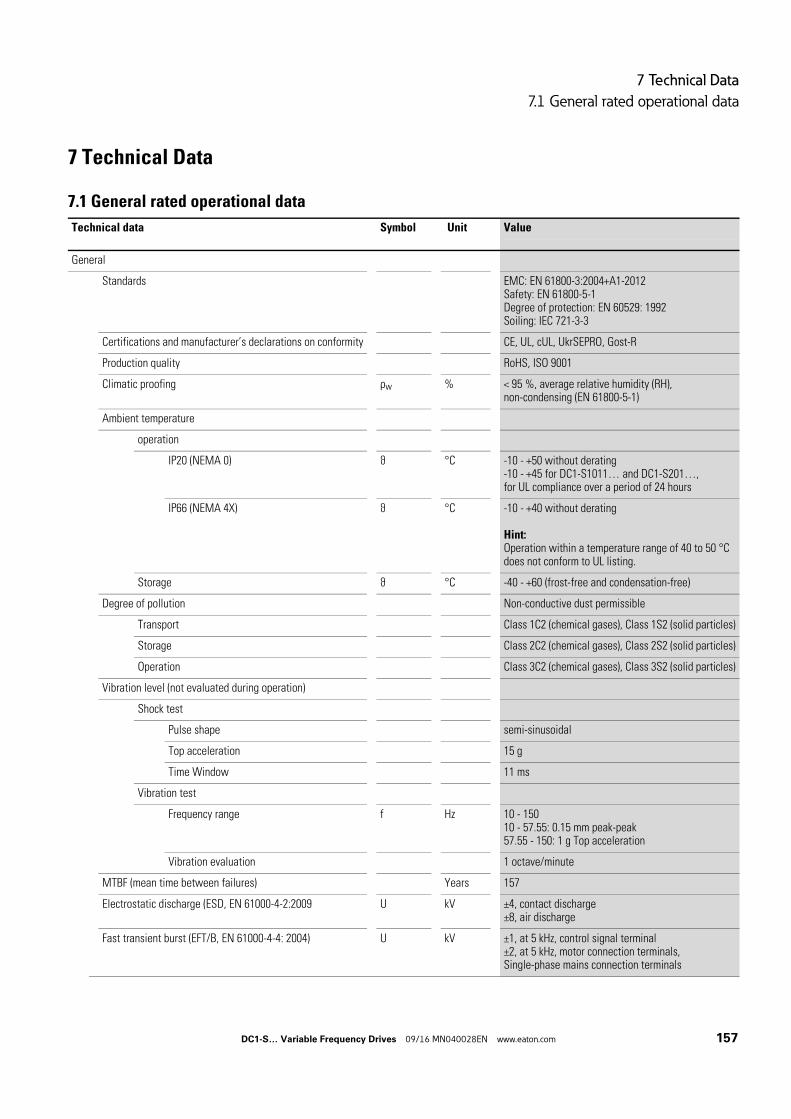
7 Technical Data
7.1 General rated operational data
7 Technical Data
7.1 General rated operational data
Technical data Symbol Unit Value
General
Standards EMC: EN 61800-3:2004+A1-2012Safety: EN 61800-5-1Degree of protection: EN 60529: 1992Soiling: IEC 721-3-3
Certifications and manufacturer’s declarations on conformity CE, UL, cUL, UkrSEPRO, Gost-R
Production quality RoHS, ISO 9001
Climatic proofing ρw % < 95 %, average relative humidity (RH), non-condensing (EN 61800-5-1)
Ambient temperature
operation
IP20 (NEMA 0) ϑ °C -10 - +50 without derating-10 - +45 for DC1-S1011… and DC1-S201…,for UL compliance over a period of 24 hours
IP66 (NEMA 4X) ϑ °C -10 - +40 without derating
Hint:Operation within a temperature range of 40 to 50 °C does not conform to UL listing.
Storage ϑ °C -40 - +60 (frost-free and condensation-free)
Degree of pollution Non-conductive dust permissible
Transport Class 1C2 (chemical gases), Class 1S2 (solid particles)
Storage Class 2C2 (chemical gases), Class 2S2 (solid particles)
Operation Class 3C2 (chemical gases), Class 3S2 (solid particles)
Vibration level (not evaluated during operation)
Shock test
Pulse shape semi-sinusoidal
Top acceleration 15 g
Time Window 11 ms
Vibration test
Frequency range f Hz 10 - 15010 - 57.55: 0.15 mm peak-peak57.55 - 150: 1 g Top acceleration
Vibration evaluation 1 octave/minute
MTBF (mean time between failures) Years 157
Electrostatic discharge (ESD, EN 61000-4-2:2009 U kV ±4, contact discharge±8, air discharge
Fast transient burst (EFT/B, EN 61000-4-4: 2004) U kV ±1, at 5 kHz, control signal terminal±2, at 5 kHz, motor connection terminals,Single-phase mains connection terminals
DC1-S… Variable Frequency Drives 09/16 MN040028EN www.eaton.com 157
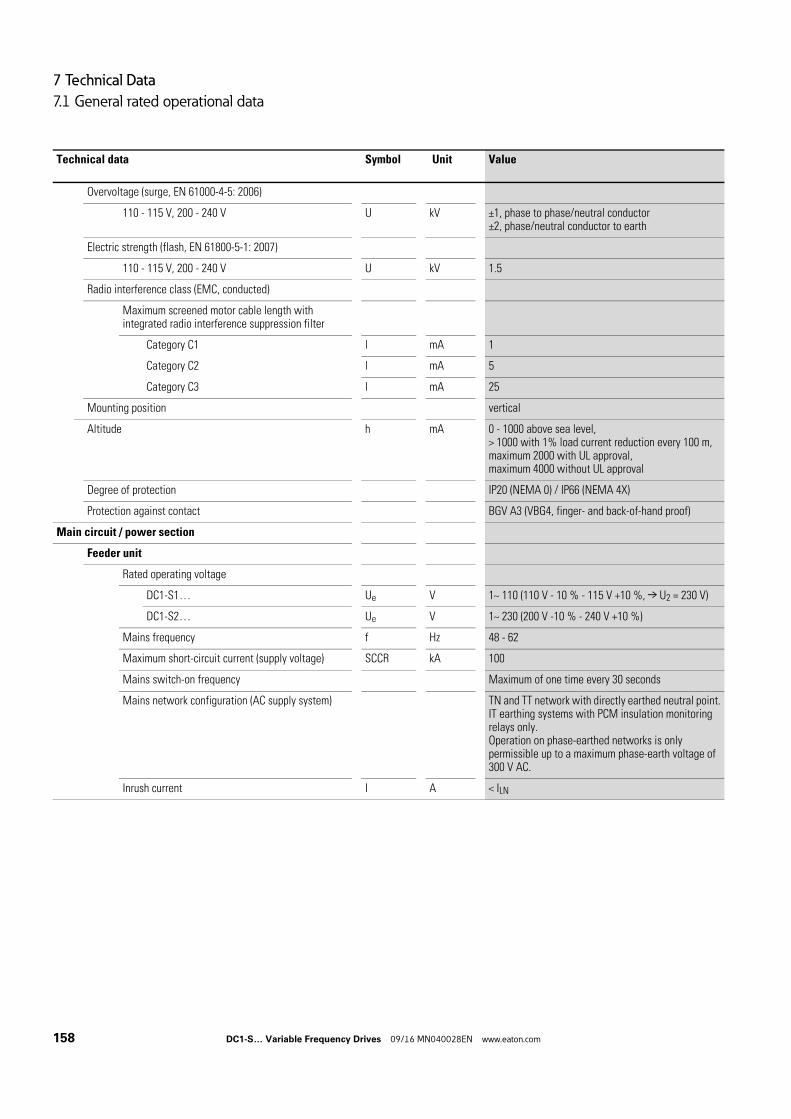
7 Technical Data
7.1 General rated operational data
Overvoltage (surge, EN 61000-4-5: 2006)
110 - 115 V, 200 - 240 V U kV ±1, phase to phase/neutral conductor±2, phase/neutral conductor to earth
Electric strength (flash, EN 61800-5-1: 2007)
110 - 115 V, 200 - 240 V U kV 1.5
Radio interference class (EMC, conducted)
Maximum screened motor cable length with integrated radio interference suppression filter
Category C1 l mA 1
Category C2 l mA 5
Category C3 l mA 25
Mounting position vertical
Altitude h mA 0 - 1000 above sea level,> 1000 with 1% load current reduction every 100 m,maximum 2000 with UL approval,maximum 4000 without UL approval
Degree of protection IP20 (NEMA 0) / IP66 (NEMA 4X)
Protection against contact BGV A3 (VBG4, finger- and back-of-hand proof)
Main circuit / power section
Feeder unit
Rated operating voltage
DC1-S1… Ue V 1~ 110 (110 V - 10 % - 115 V +10 %, → U2 = 230 V)
DC1-S2… Ue V 1~ 230 (200 V -10 % - 240 V +10 %)
Mains frequency f Hz 48 - 62
Maximum short-circuit current (supply voltage) SCCR kA 100
Mains switch-on frequency Maximum of one time every 30 seconds
Mains network configuration (AC supply system) TN and TT network with directly earthed neutral point.IT earthing systems with PCM insulation monitoring relays only.Operation on phase-earthed networks is only permissible up to a maximum phase-earth voltage of 300 V AC.
Inrush current I A < ILN
Technical data Symbol Unit Value
158 DC1-S… Variable Frequency Drives 09/16 MN040028EN www.eaton.com
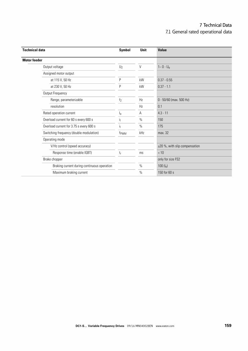
7 Technical Data
7.1 General rated operational data
Motor feeder
Output voltage U2 V 1~ 0 - Ue
Assigned motor output
at 115 V, 50 Hz P kW 0.37 - 0.55
at 230 V, 50 Hz P kW 0.37 - 1.1
Output Frequency
Range, parameterizable f2 Hz 0 - 50/60 (max. 500 Hz)
resolution Hz 0.1
Rated operation current Ie A 4.3 - 11
Overload current for 60 s every 600 s il % 150
Overload current for 3.75 s every 600 s il % 175
Switching frequency (double modulation) fPWM kHz max. 32
Operating mode
V/Hz control (speed accuracy) ±20 %, with slip compensation
Response time (enable IGBT) tr ms < 10
Brake chopper only for size FS2
Braking current during continuous operation % 100 (Ie)
Maximum braking current % 150 for 60 s
Technical data Symbol Unit Value
DC1-S… Variable Frequency Drives 09/16 MN040028EN www.eaton.com 159
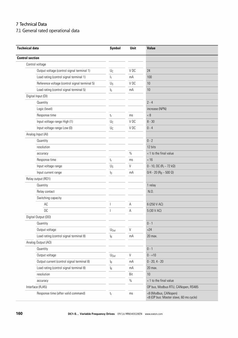
7 Technical Data
7.1 General rated operational data
Control section
Control voltage
Output voltage (control signal terminal 1) UC V DC 24
Load rating (control signal terminal 1) I1 mA 100
Reference voltage (control signal terminal 5) US V DC 10
Load rating (control signal terminal 5) I5 mA 10
Digital Input (DI)
Quantity 2 - 4
Logic (level) increase (NPN)
Response time tr ms < 8
Input voltage range High (1) UC V DC 8 - 30
Input voltage range Low (0) UC V DC 0 - 4
Analog Input (AI)
Quantity 0 - 2
resolution 12 bits
accuracy % < 1 to the final value
Response time tr ms < 16
Input voltage range US V 0 - 10, DC (Ri ~ 72 kΩ)
Input current range IS mA 0/4 - 20 (RB ~ 500 Ω)
Relay output (RO1)
Quantity 1 relay
Relay contact N.O.
Switching capacity
AC I A 6 (250 V AC)
DC I A 5 (30 V AC)
Digital Output (DO)
Quantity 0 - 1
Output voltage UOut V +24
Load rating (control signal terminal 8) I8 mA 20 max.
Analog Output (AO)
Quantity 0 - 1
Output voltage UOut V 0 - +10
Output current (control signal terminal 8) I8 mA 0 - 20, 4 - 20
Load rating (control signal terminal 8) I8 mA 20 max.
resolution Bit 10
accuracy % < 1 to the final value
Interface (RJ45) OP bus, Modbus RTU, CANopen, RS485
Response time (after valid command) tr ms <8 (Modbus, CANopen)<8 (OP bus: Master slave, 60 ms cycle)
Technical data Symbol Unit Value
160 DC1-S… Variable Frequency Drives 09/16 MN040028EN www.eaton.com
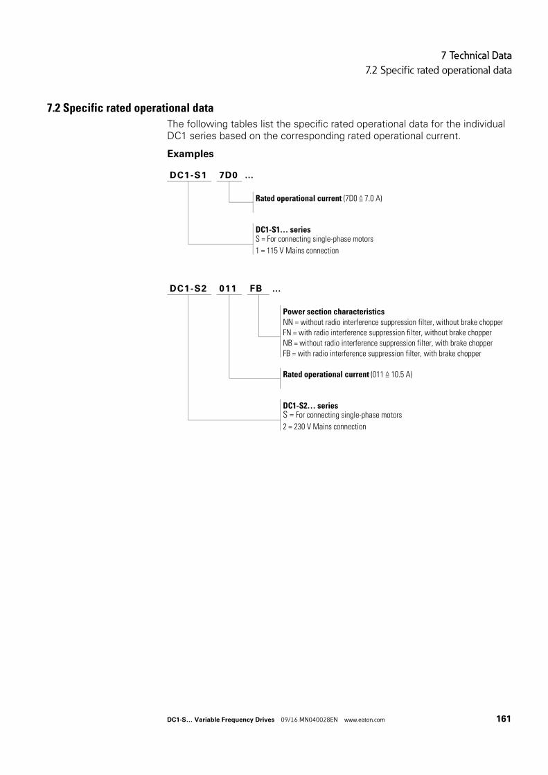
7 Technical Data
7.2 Specific rated operational data
7.2 Specific rated operational data
The following tables list the specific rated operational data for the individual DC1 series based on the corresponding rated operational current.
Examples
DC1-S1 7D0 …
Rated operational current (7D0 ≙ 7.0 A)
DC1-S1… seriesS = For connecting single-phase motors
1 = 115 V Mains connection
DC1-S2 011 FB …
Power section characteristics
NN = without radio interference suppression filter, without brake chopper
FN = with radio interference suppression filter, without brake chopper
NB = without radio interference suppression filter, with brake chopper
FB = with radio interference suppression filter, with brake chopper
Rated operational current (011 ≙ 10.5 A)
DC1-S2… seriesS = For connecting single-phase motors
2 = 230 V Mains connection
DC1-S… Variable Frequency Drives 09/16 MN040028EN www.eaton.com 161
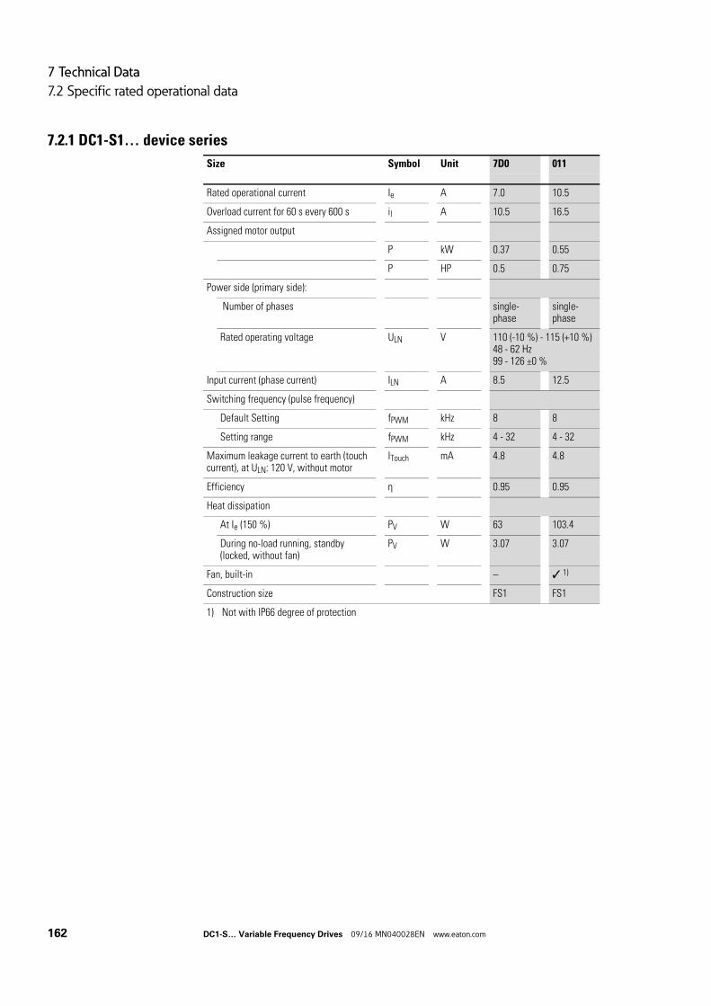
7 Technical Data
7.2 Specific rated operational data
7.2.1 DC1-S1… device series
Size Symbol Unit 7D0 011
Rated operational current Ie A 7.0 10.5
Overload current for 60 s every 600 s il A 10.5 16.5
Assigned motor output
P kW 0.37 0.55
P HP 0.5 0.75
Power side (primary side):
Number of phases single-phase
single-phase
Rated operating voltage ULN V 110 (-10 %) - 115 (+10 %) 48 - 62 Hz99 - 126 ±0 %
Input current (phase current) ILN A 8.5 12.5
Switching frequency (pulse frequency)
Default Setting fPWM kHz 8 8
Setting range fPWM kHz 4 - 32 4 - 32
Maximum leakage current to earth (touch current), at ULN: 120 V, without motor
ITouch mA 4.8 4.8
Efficiency η 0.95 0.95
Heat dissipation
At Ie (150 %) PV W 63 103.4
During no-load running, standby (locked, without fan)
PV W 3.07 3.07
Fan, built-in – 1)
Construction size FS1 FS1
1) Not with IP66 degree of protection
162 DC1-S… Variable Frequency Drives 09/16 MN040028EN www.eaton.com
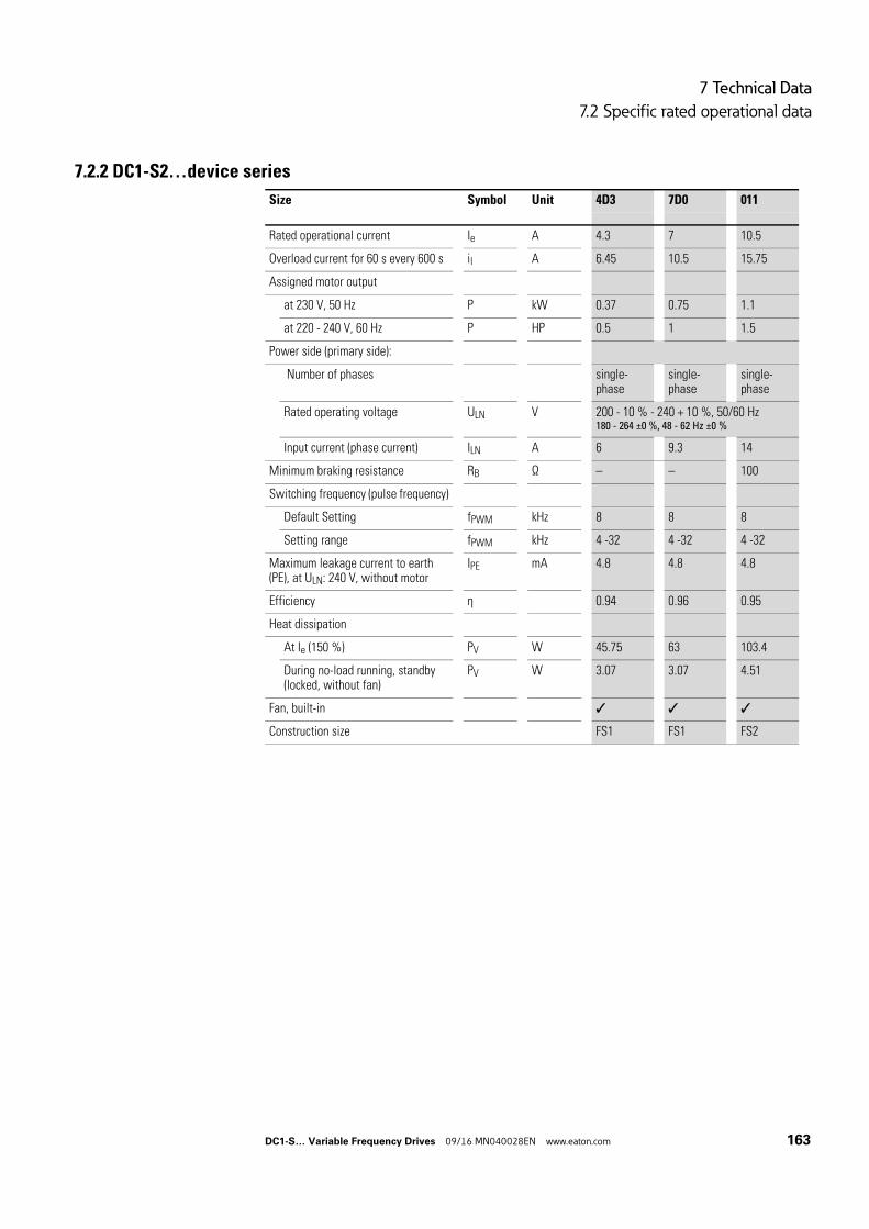
7 Technical Data
7.2 Specific rated operational data
7.2.2 DC1-S2…device series
Size Symbol Unit 4D3 7D0 011
Rated operational current Ie A 4.3 7 10.5
Overload current for 60 s every 600 s il A 6.45 10.5 15.75
Assigned motor output
at 230 V, 50 Hz P kW 0.37 0.75 1.1
at 220 - 240 V, 60 Hz P HP 0.5 1 1.5
Power side (primary side):
Number of phases single-phase
single-phase
single-phase
Rated operating voltage ULN V 200 - 10 % - 240 + 10 %, 50/60 Hz180 - 264 ±0 %, 48 - 62 Hz ±0 %
Input current (phase current) ILN A 6 9.3 14
Minimum braking resistance RB Ω – – 100
Switching frequency (pulse frequency)
Default Setting fPWM kHz 8 8 8
Setting range fPWM kHz 4 -32 4 -32 4 -32
Maximum leakage current to earth (PE), at ULN: 240 V, without motor
IPE mA 4.8 4.8 4.8
Efficiency η 0.94 0.96 0.95
Heat dissipation
At Ie (150 %) PV W 45.75 63 103.4
During no-load running, standby (locked, without fan)
PV W 3.07 3.07 4.51
Fan, built-in
Construction size FS1 FS1 FS2
DC1-S… Variable Frequency Drives 09/16 MN040028EN www.eaton.com 163
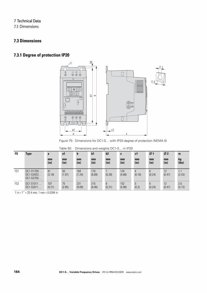
7 Technical Data
7.3 Dimensions
7.3 Dimensions
7.3.1 Degree of protection IP20
Figure 75: Dimensions for DC1-S… with IP20 degree of protection (NEMA 0)
Table 50: Dimensions and weights DC1-S… in IP20
c
c1
VAR
EMC
bb1
a
a1
1 2 3 4 5 6 7 8 9 10 11
1
2
b2
FS Type a a1 b b1 b2 c c1 1 2 m
mm(in)
mm(in)
mm(in)
mm(in)
mm(in)
mm(in)
mm(in)
mm(in)
mm(in)
kg(lbs)
FS1 DC1-S17D0…DC1-S24D3…DC1-S27D0…
81(3.19)
50(1.97)
184(7.24)
170(6.69)
7(0.28)
124(4.88)
4(0.16)
6(0.24)
12(0.47)
1.1(2.43)
FS2 DC1-S1011…DC1-S2011…
107(4.21)
75(2.95)
231(9.09)
215(8.46)
8(0.31)
152(5.98)
5(0.2)
6(0.24)
12(0.47)
2.6(5.73)
1 in = 1’’ = 25.4 mm, 1 mm = 0.0394 in
164 DC1-S… Variable Frequency Drives 09/16 MN040028EN www.eaton.com
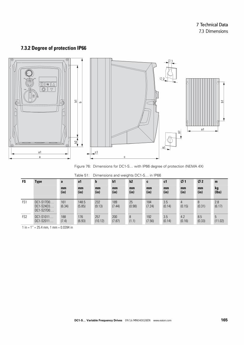
7 Technical Data
7.3 Dimensions
7.3.2 Degree of protection IP66
Figure 76: Dimensions for DC1-S… with IP66 degree of protection (NEMA 4X)
Table 51: Dimensions and weights DC1-S… in IP66
REV FWD0
ON
OFFPWR
b
a c
a1 c1
b1b2
a1
b1
1
2
a1
b1
FS Type a a1 b b1 b2 c c1 1 2 m
mm(in)
mm(in)
mm(in)
mm(in)
mm(in)
mm(in)
mm(in)
mm(in)
mm(in)
kg(lbs)
FS1 DC1-S17D0…DC1-S24D3…DC1-S27D0…
161(6.34)
148.5(5.85)
232(9.13)
189(7.44)
25(0.98)
184(7.24)
3.5(0.14)
4(0.15)
8(0.31)
2.8(6.17)
FS2 DC1-S1011…DC1-S2011…
188(7.4)
176(6.93)
257(10.12)
200(7.87)
8(1.1)
192(7.56)
3.5(0.14)
4.2(0.16)
8.5(0.33)
5(11.02)
1 in = 1’’ = 25.4 mm, 1 mm = 0.0394 in
DC1-S… Variable Frequency Drives 09/16 MN040028EN www.eaton.com 165

7 Technical Data
7.3 Dimensions
166 DC1-S… Variable Frequency Drives 09/16 MN040028EN www.eaton.com
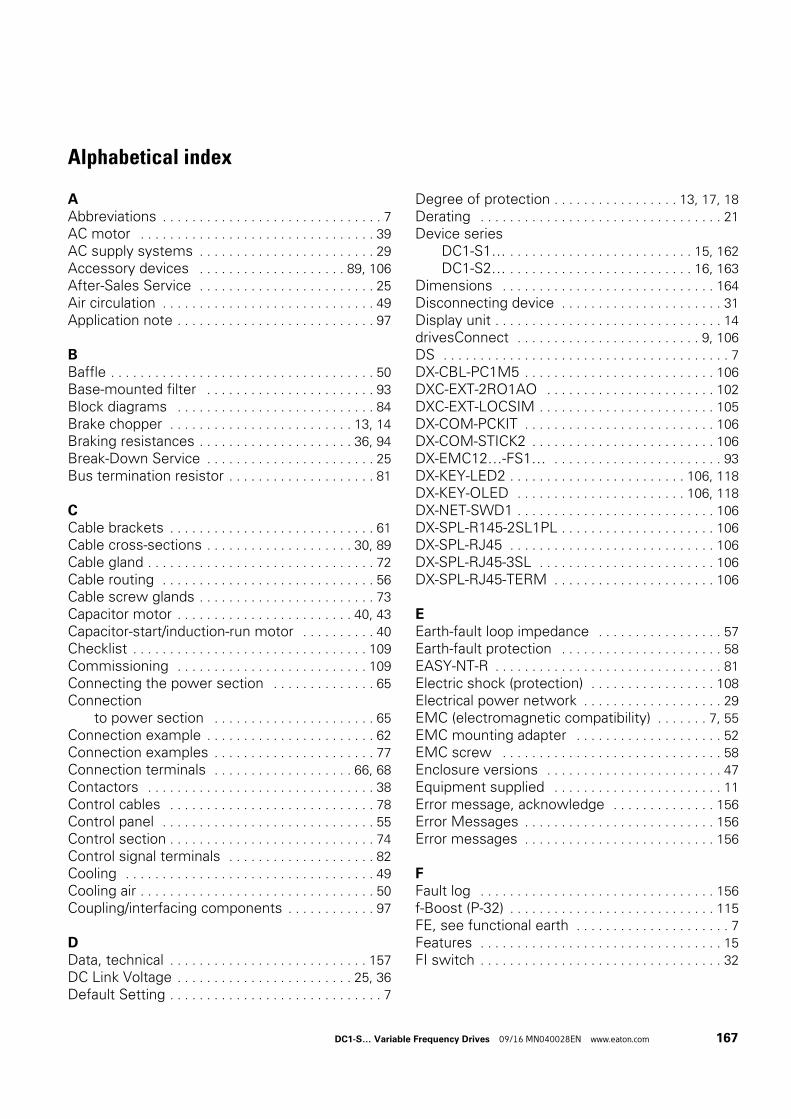
Alphabetical index
AAbbreviations . . . . . . . . . . . . . . . . . . . . . . . . . . . . . . 7
AC motor . . . . . . . . . . . . . . . . . . . . . . . . . . . . . . . . 39
AC supply systems . . . . . . . . . . . . . . . . . . . . . . . . 29
Accessory devices . . . . . . . . . . . . . . . . . . . . 89, 106
After-Sales Service . . . . . . . . . . . . . . . . . . . . . . . . 25
Air circulation . . . . . . . . . . . . . . . . . . . . . . . . . . . . . 49
Application note . . . . . . . . . . . . . . . . . . . . . . . . . . . 97
BBaffle . . . . . . . . . . . . . . . . . . . . . . . . . . . . . . . . . . . . 50
Base-mounted filter . . . . . . . . . . . . . . . . . . . . . . . 93
Block diagrams . . . . . . . . . . . . . . . . . . . . . . . . . . . 84
Brake chopper . . . . . . . . . . . . . . . . . . . . . . . . . 13, 14
Braking resistances . . . . . . . . . . . . . . . . . . . . . 36, 94
Break-Down Service . . . . . . . . . . . . . . . . . . . . . . . 25
Bus termination resistor . . . . . . . . . . . . . . . . . . . . 81
CCable brackets . . . . . . . . . . . . . . . . . . . . . . . . . . . . 61
Cable cross-sections . . . . . . . . . . . . . . . . . . . . 30, 89
Cable gland . . . . . . . . . . . . . . . . . . . . . . . . . . . . . . . 72
Cable routing . . . . . . . . . . . . . . . . . . . . . . . . . . . . . 56
Cable screw glands . . . . . . . . . . . . . . . . . . . . . . . . 73
Capacitor motor . . . . . . . . . . . . . . . . . . . . . . . . 40, 43
Capacitor-start/induction-run motor . . . . . . . . . . 40
Checklist . . . . . . . . . . . . . . . . . . . . . . . . . . . . . . . . 109
Commissioning . . . . . . . . . . . . . . . . . . . . . . . . . . 109
Connecting the power section . . . . . . . . . . . . . . 65
Connectionto power section . . . . . . . . . . . . . . . . . . . . . . 65
Connection example . . . . . . . . . . . . . . . . . . . . . . . 62
Connection examples . . . . . . . . . . . . . . . . . . . . . . 77
Connection terminals . . . . . . . . . . . . . . . . . . . 66, 68
Contactors . . . . . . . . . . . . . . . . . . . . . . . . . . . . . . . 38
Control cables . . . . . . . . . . . . . . . . . . . . . . . . . . . . 78
Control panel . . . . . . . . . . . . . . . . . . . . . . . . . . . . . 55
Control section . . . . . . . . . . . . . . . . . . . . . . . . . . . . 74
Control signal terminals . . . . . . . . . . . . . . . . . . . . 82
Cooling . . . . . . . . . . . . . . . . . . . . . . . . . . . . . . . . . . 49
Cooling air . . . . . . . . . . . . . . . . . . . . . . . . . . . . . . . . 50
Coupling/interfacing components . . . . . . . . . . . . 97
DData, technical . . . . . . . . . . . . . . . . . . . . . . . . . . . 157
DC Link Voltage . . . . . . . . . . . . . . . . . . . . . . . . 25, 36
Default Setting . . . . . . . . . . . . . . . . . . . . . . . . . . . . . 7
Degree of protection . . . . . . . . . . . . . . . . . 13, 17, 18
Derating . . . . . . . . . . . . . . . . . . . . . . . . . . . . . . . . . 21
Device seriesDC1-S1… . . . . . . . . . . . . . . . . . . . . . . . . . 15, 162
DC1-S2… . . . . . . . . . . . . . . . . . . . . . . . . . 16, 163
Dimensions . . . . . . . . . . . . . . . . . . . . . . . . . . . . . 164
Disconnecting device . . . . . . . . . . . . . . . . . . . . . . 31
Display unit . . . . . . . . . . . . . . . . . . . . . . . . . . . . . . . 14
drivesConnect . . . . . . . . . . . . . . . . . . . . . . . . . 9, 106
DS . . . . . . . . . . . . . . . . . . . . . . . . . . . . . . . . . . . . . . . 7
DX-CBL-PC1M5 . . . . . . . . . . . . . . . . . . . . . . . . . . 106
DXC-EXT-2RO1AO . . . . . . . . . . . . . . . . . . . . . . . 102
DXC-EXT-LOCSIM . . . . . . . . . . . . . . . . . . . . . . . . 105
DX-COM-PCKIT . . . . . . . . . . . . . . . . . . . . . . . . . . 106
DX-COM-STICK2 . . . . . . . . . . . . . . . . . . . . . . . . . 106
DX-EMC12…-FS1… . . . . . . . . . . . . . . . . . . . . . . . 93
DX-KEY-LED2 . . . . . . . . . . . . . . . . . . . . . . . . 106, 118
DX-KEY-OLED . . . . . . . . . . . . . . . . . . . . . . . 106, 118
DX-NET-SWD1 . . . . . . . . . . . . . . . . . . . . . . . . . . . 106
DX-SPL-R145-2SL1PL . . . . . . . . . . . . . . . . . . . . . 106
DX-SPL-RJ45 . . . . . . . . . . . . . . . . . . . . . . . . . . . . 106
DX-SPL-RJ45-3SL . . . . . . . . . . . . . . . . . . . . . . . . 106
DX-SPL-RJ45-TERM . . . . . . . . . . . . . . . . . . . . . . 106
EEarth-fault loop impedance . . . . . . . . . . . . . . . . . 57
Earth-fault protection . . . . . . . . . . . . . . . . . . . . . . 58
EASY-NT-R . . . . . . . . . . . . . . . . . . . . . . . . . . . . . . . 81
Electric shock (protection) . . . . . . . . . . . . . . . . . 108
Electrical power network . . . . . . . . . . . . . . . . . . . 29
EMC (electromagnetic compatibility) . . . . . . . 7, 55
EMC mounting adapter . . . . . . . . . . . . . . . . . . . . 52
EMC screw . . . . . . . . . . . . . . . . . . . . . . . . . . . . . . 58
Enclosure versions . . . . . . . . . . . . . . . . . . . . . . . . 47
Equipment supplied . . . . . . . . . . . . . . . . . . . . . . . 11
Error message, acknowledge . . . . . . . . . . . . . . 156
Error Messages . . . . . . . . . . . . . . . . . . . . . . . . . . 156
Error messages . . . . . . . . . . . . . . . . . . . . . . . . . . 156
FFault log . . . . . . . . . . . . . . . . . . . . . . . . . . . . . . . . 156
f-Boost (P-32) . . . . . . . . . . . . . . . . . . . . . . . . . . . . 115
FE, see functional earth . . . . . . . . . . . . . . . . . . . . . 7
Features . . . . . . . . . . . . . . . . . . . . . . . . . . . . . . . . . 15
FI switch . . . . . . . . . . . . . . . . . . . . . . . . . . . . . . . . . 32
DC1-S… Variable Frequency Drives 09/16 MN040028EN www.eaton.com 167
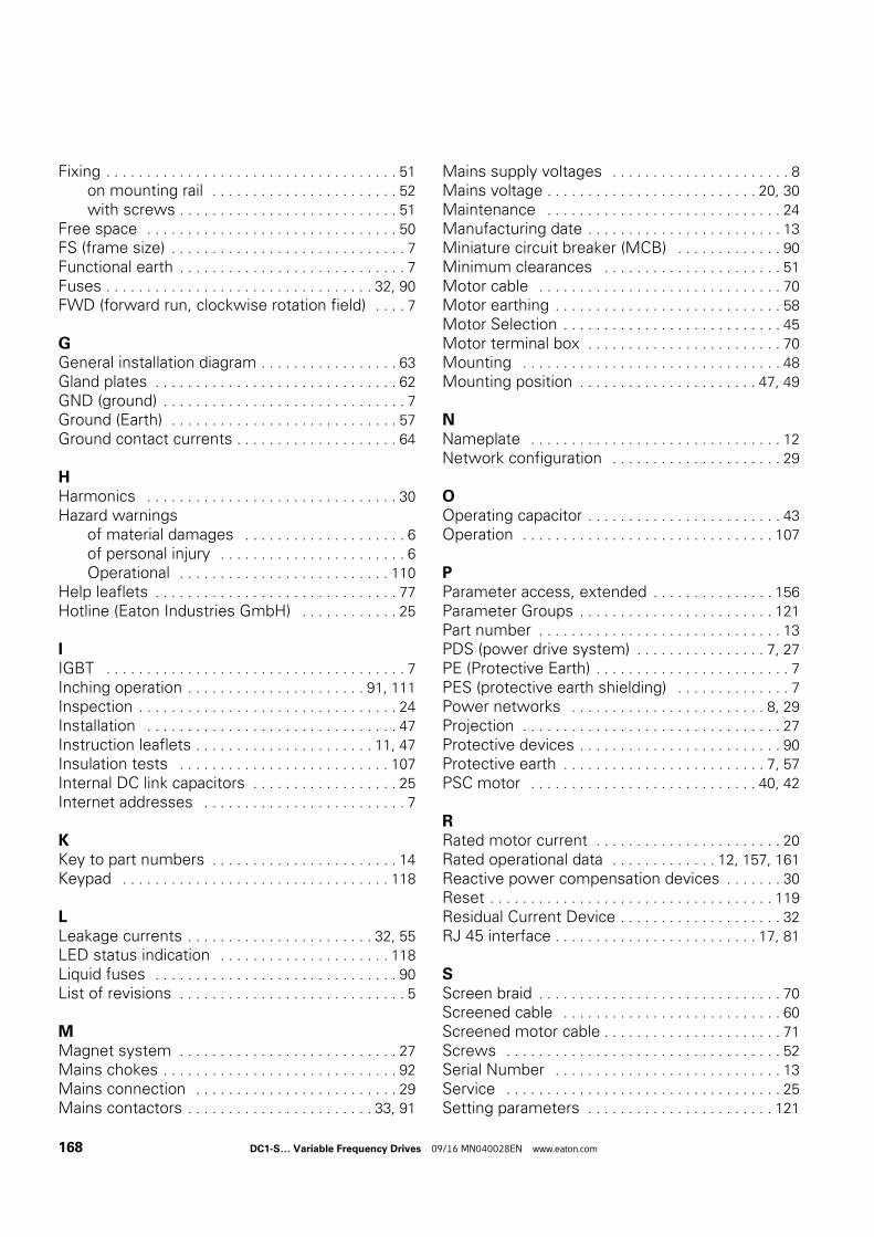
Fixing . . . . . . . . . . . . . . . . . . . . . . . . . . . . . . . . . . . . 51
on mounting rail . . . . . . . . . . . . . . . . . . . . . . . 52
with screws . . . . . . . . . . . . . . . . . . . . . . . . . . . 51
Free space . . . . . . . . . . . . . . . . . . . . . . . . . . . . . . . 50
FS (frame size) . . . . . . . . . . . . . . . . . . . . . . . . . . . . . 7
Functional earth . . . . . . . . . . . . . . . . . . . . . . . . . . . . 7
Fuses . . . . . . . . . . . . . . . . . . . . . . . . . . . . . . . . . 32, 90
FWD (forward run, clockwise rotation field) . . . . 7
GGeneral installation diagram . . . . . . . . . . . . . . . . . 63
Gland plates . . . . . . . . . . . . . . . . . . . . . . . . . . . . . . 62
GND (ground) . . . . . . . . . . . . . . . . . . . . . . . . . . . . . . 7
Ground (Earth) . . . . . . . . . . . . . . . . . . . . . . . . . . . . 57
Ground contact currents . . . . . . . . . . . . . . . . . . . . 64
HHarmonics . . . . . . . . . . . . . . . . . . . . . . . . . . . . . . . 30
Hazard warningsof material damages . . . . . . . . . . . . . . . . . . . . 6
of personal injury . . . . . . . . . . . . . . . . . . . . . . . 6
Operational . . . . . . . . . . . . . . . . . . . . . . . . . . 110
Help leaflets . . . . . . . . . . . . . . . . . . . . . . . . . . . . . . 77
Hotline (Eaton Industries GmbH) . . . . . . . . . . . . 25
IIGBT . . . . . . . . . . . . . . . . . . . . . . . . . . . . . . . . . . . . . 7
Inching operation . . . . . . . . . . . . . . . . . . . . . . 91, 111
Inspection . . . . . . . . . . . . . . . . . . . . . . . . . . . . . . . . 24
Installation . . . . . . . . . . . . . . . . . . . . . . . . . . . . . . . 47
Instruction leaflets . . . . . . . . . . . . . . . . . . . . . . 11, 47
Insulation tests . . . . . . . . . . . . . . . . . . . . . . . . . . 107
Internal DC link capacitors . . . . . . . . . . . . . . . . . . 25
Internet addresses . . . . . . . . . . . . . . . . . . . . . . . . . 7
KKey to part numbers . . . . . . . . . . . . . . . . . . . . . . . 14
Keypad . . . . . . . . . . . . . . . . . . . . . . . . . . . . . . . . . 118
LLeakage currents . . . . . . . . . . . . . . . . . . . . . . . 32, 55
LED status indication . . . . . . . . . . . . . . . . . . . . . 118
Liquid fuses . . . . . . . . . . . . . . . . . . . . . . . . . . . . . . 90
List of revisions . . . . . . . . . . . . . . . . . . . . . . . . . . . . 5
MMagnet system . . . . . . . . . . . . . . . . . . . . . . . . . . . 27
Mains chokes . . . . . . . . . . . . . . . . . . . . . . . . . . . . . 92
Mains connection . . . . . . . . . . . . . . . . . . . . . . . . . 29
Mains contactors . . . . . . . . . . . . . . . . . . . . . . . 33, 91
Mains supply voltages . . . . . . . . . . . . . . . . . . . . . . 8
Mains voltage . . . . . . . . . . . . . . . . . . . . . . . . . . 20, 30
Maintenance . . . . . . . . . . . . . . . . . . . . . . . . . . . . . 24
Manufacturing date . . . . . . . . . . . . . . . . . . . . . . . . 13
Miniature circuit breaker (MCB) . . . . . . . . . . . . . 90
Minimum clearances . . . . . . . . . . . . . . . . . . . . . . 51
Motor cable . . . . . . . . . . . . . . . . . . . . . . . . . . . . . . 70
Motor earthing . . . . . . . . . . . . . . . . . . . . . . . . . . . . 58
Motor Selection . . . . . . . . . . . . . . . . . . . . . . . . . . . 45
Motor terminal box . . . . . . . . . . . . . . . . . . . . . . . . 70
Mounting . . . . . . . . . . . . . . . . . . . . . . . . . . . . . . . . 48
Mounting position . . . . . . . . . . . . . . . . . . . . . . 47, 49
NNameplate . . . . . . . . . . . . . . . . . . . . . . . . . . . . . . . 12
Network configuration . . . . . . . . . . . . . . . . . . . . . 29
OOperating capacitor . . . . . . . . . . . . . . . . . . . . . . . . 43
Operation . . . . . . . . . . . . . . . . . . . . . . . . . . . . . . . 107
PParameter access, extended . . . . . . . . . . . . . . . 156
Parameter Groups . . . . . . . . . . . . . . . . . . . . . . . . 121
Part number . . . . . . . . . . . . . . . . . . . . . . . . . . . . . . 13
PDS (power drive system) . . . . . . . . . . . . . . . . 7, 27
PE (Protective Earth) . . . . . . . . . . . . . . . . . . . . . . . . 7
PES (protective earth shielding) . . . . . . . . . . . . . . 7
Power networks . . . . . . . . . . . . . . . . . . . . . . . . 8, 29
Projection . . . . . . . . . . . . . . . . . . . . . . . . . . . . . . . . 27
Protective devices . . . . . . . . . . . . . . . . . . . . . . . . . 90
Protective earth . . . . . . . . . . . . . . . . . . . . . . . . . 7, 57
PSC motor . . . . . . . . . . . . . . . . . . . . . . . . . . . . 40, 42
RRated motor current . . . . . . . . . . . . . . . . . . . . . . . 20
Rated operational data . . . . . . . . . . . . . 12, 157, 161
Reactive power compensation devices . . . . . . . 30
Reset . . . . . . . . . . . . . . . . . . . . . . . . . . . . . . . . . . . 119
Residual Current Device . . . . . . . . . . . . . . . . . . . . 32
RJ 45 interface . . . . . . . . . . . . . . . . . . . . . . . . . 17, 81
SScreen braid . . . . . . . . . . . . . . . . . . . . . . . . . . . . . . 70
Screened cable . . . . . . . . . . . . . . . . . . . . . . . . . . . 60
Screened motor cable . . . . . . . . . . . . . . . . . . . . . . 71
Screws . . . . . . . . . . . . . . . . . . . . . . . . . . . . . . . . . . 52
Serial Number . . . . . . . . . . . . . . . . . . . . . . . . . . . . 13
Service . . . . . . . . . . . . . . . . . . . . . . . . . . . . . . . . . . 25
Setting parameters . . . . . . . . . . . . . . . . . . . . . . . 121
168 DC1-S… Variable Frequency Drives 09/16 MN040028EN www.eaton.com
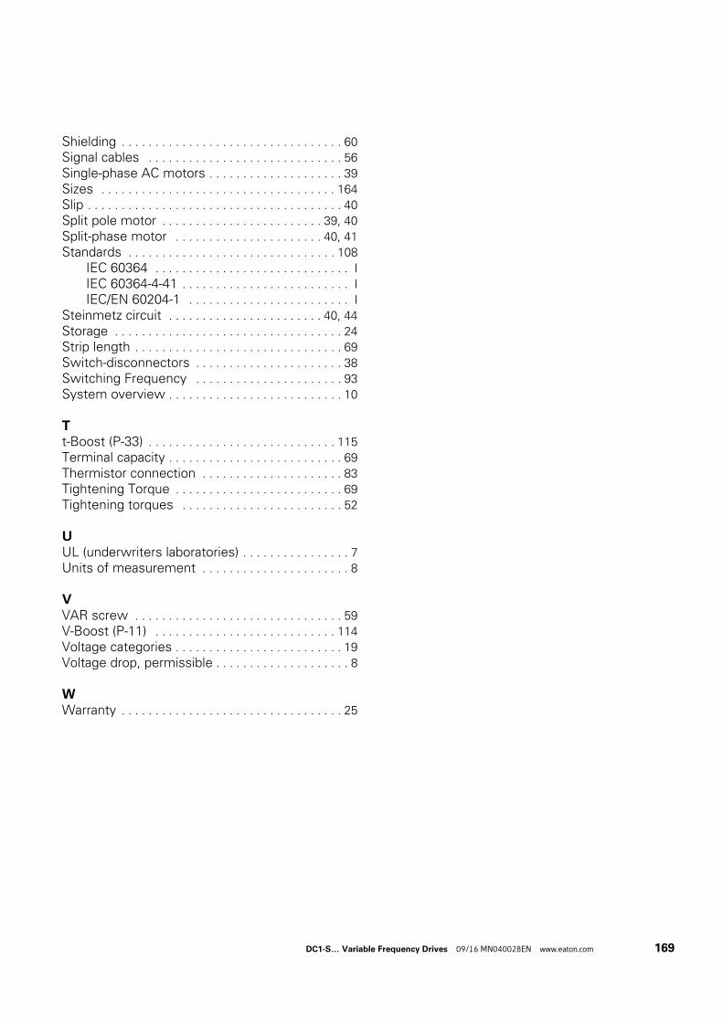
Shielding . . . . . . . . . . . . . . . . . . . . . . . . . . . . . . . . . 60
Signal cables . . . . . . . . . . . . . . . . . . . . . . . . . . . . . 56
Single-phase AC motors . . . . . . . . . . . . . . . . . . . . 39
Sizes . . . . . . . . . . . . . . . . . . . . . . . . . . . . . . . . . . . 164
Slip . . . . . . . . . . . . . . . . . . . . . . . . . . . . . . . . . . . . . . 40
Split pole motor . . . . . . . . . . . . . . . . . . . . . . . . 39, 40
Split-phase motor . . . . . . . . . . . . . . . . . . . . . . 40, 41
Standards . . . . . . . . . . . . . . . . . . . . . . . . . . . . . . . 108
IEC 60364 . . . . . . . . . . . . . . . . . . . . . . . . . . . . . I
IEC 60364-4-41 . . . . . . . . . . . . . . . . . . . . . . . . . I
IEC/EN 60204-1 . . . . . . . . . . . . . . . . . . . . . . . . I
Steinmetz circuit . . . . . . . . . . . . . . . . . . . . . . . 40, 44
Storage . . . . . . . . . . . . . . . . . . . . . . . . . . . . . . . . . . 24
Strip length . . . . . . . . . . . . . . . . . . . . . . . . . . . . . . . 69
Switch-disconnectors . . . . . . . . . . . . . . . . . . . . . . 38
Switching Frequency . . . . . . . . . . . . . . . . . . . . . . 93
System overview . . . . . . . . . . . . . . . . . . . . . . . . . . 10
Tt-Boost (P-33) . . . . . . . . . . . . . . . . . . . . . . . . . . . . 115
Terminal capacity . . . . . . . . . . . . . . . . . . . . . . . . . . 69
Thermistor connection . . . . . . . . . . . . . . . . . . . . . 83
Tightening Torque . . . . . . . . . . . . . . . . . . . . . . . . . 69
Tightening torques . . . . . . . . . . . . . . . . . . . . . . . . 52
UUL (underwriters laboratories) . . . . . . . . . . . . . . . . 7
Units of measurement . . . . . . . . . . . . . . . . . . . . . . 8
VVAR screw . . . . . . . . . . . . . . . . . . . . . . . . . . . . . . . 59
V-Boost (P-11) . . . . . . . . . . . . . . . . . . . . . . . . . . . 114
Voltage categories . . . . . . . . . . . . . . . . . . . . . . . . . 19
Voltage drop, permissible . . . . . . . . . . . . . . . . . . . . 8
WWarranty . . . . . . . . . . . . . . . . . . . . . . . . . . . . . . . . . 25
DC1-S… Variable Frequency Drives 09/16 MN040028EN www.eaton.com 169


