• Temperature range: 5°C a 80°C in continous working. Nominal pressure in function of the temeprature according diagramm..• High impact ressitance. High toghness.• Good insulating.• Light weight.• High thermal expansion.• Non toxic and taint-free. Suitable for food and drinking use.• Resistant to acids, alkalis, salts and organic solutions.• Ideal for installations above or below ground.• Jointing by thread, socket fusion or butt welding.• Not resistant to concentred oxidising acids.
• Rango de temperaturas: 5°C a 80°C en trabajo continuo. Presión nominal en función de la temperatura según gráfico.• Alta resistencia al impacto. Alta tenacidad.• Buen aislante.• Peso reducido.• Alta expansión térmica.• No tóxico y libre de corrosión. Apto para uso alimentario.• Resistente a ácidos, alcalinos, sales y soluciones orgánicas.• Ideal para instalaciones exteriores o enterradas.• Posible union roscada, por termofusión o soldadura a tope.• No resistente a ácidos oxidantes concentrados.
PPDESCRIPTION
Polypropylene (PP) piping systems are widely used in industrial processing. Light in weight yet with high impact strength and reliable heat fusion welding, PP also offers good abrasion resistance and is a good thermal and electrical insulator.PP is suitable for working use at temperatures up to 80°C, and will withstand short term use at a maximum 110°C.Chemical resistance is excellent: PP is resistant to aqueous solutions of acids, alkalis and salts, and to a large number of organic solvents.
PPDESCRIPCIÓN
Los sistemas de conducción en polipropileno (PP) son ampliamente usados en procesos industriales. De peso reducido y de gran resistencia al impacto son capaces de ser soldados, el PP también ofrece gran resistencia a la abrasión y es buen aislante térmico y eléctrico.El PP puede trabajar en temperaturas de hasta 80ºC y, a corto plazo, puede soportar hasta 110ºC.Su resistencia química es excelente: es resistente a soluciones acuosas de ácidos, alcalinos y sales, y a un gran número de disolventes orgánicos.
CEPEX EXTREME SERIES DATASHEETS
Features and BenefitsCaracterísti cas y Benefi cios
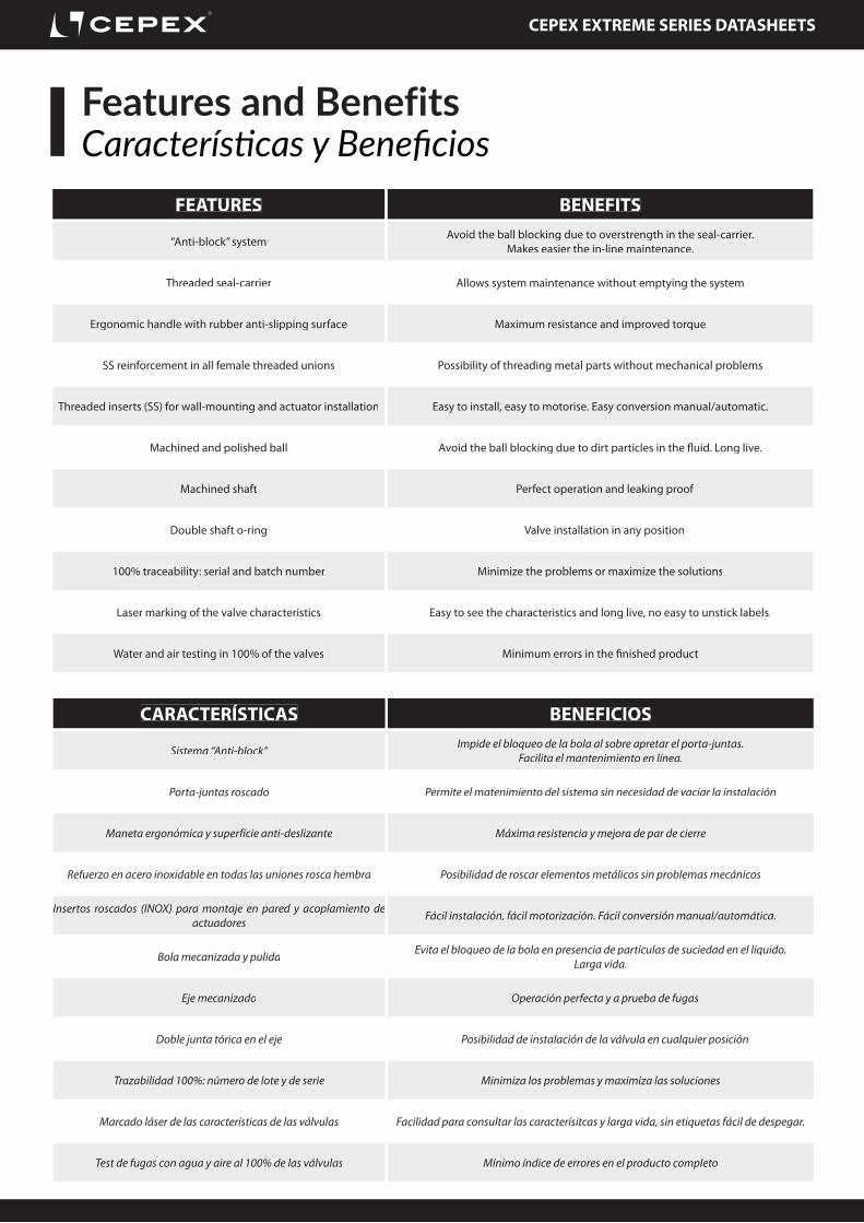
FEATURES BENEFITS
“Anti-block” system Avoid the ball blocking due to overstrength in the seal-carrier.Makes easier the in-line maintenance.
Threaded seal-carrier Allows system maintenance without emptying the system
Ergonomic handle with rubber anti-slipping surface Maximum resistance and improved torque
SS reinforcement in all female threaded unions Possibility of threading metal parts without mechanical problems
Threaded inserts (SS) for wall-mounting and actuator installation Easy to install, easy to motorise. Easy conversion manual/automatic.
Machined and polished ball Avoid the ball blocking due to dirt particles in the fl uid. Long live.
Machined shaft Perfect operation and leaking proof
Double shaft o-ring Valve installation in any position
100% traceability: serial and batch number Minimize the problems or maximize the solutions
Laser marking of the valve characteristics Easy to see the characteristics and long live, no easy to unstick labels.
Water and air testing in 100% of the valves Minimum errors in the fi nished product
CARACTERÍSTICAS BENEFICIOS
Sistema “Anti-block” Impide el bloqueo de la bola al sobre apretar el porta-juntas. Facilita el mantenimiento en línea.
Porta-juntas roscado Permite el matenimiento del sistema sin necesidad de vaciar la instalación
Maneta ergonómica y superfície anti-deslizante Máxima resistencia y mejora de par de cierre
Refuerzo en acero inoxidable en todas las uniones rosca hembra Posibilidad de roscar elementos metálicos sin problemas mecánicos
Insertos roscados (INOX) para montaje en pared y acoplamiento de actuadores Fácil instalación, fácil motorización. Fácil conversión manual/automática.
Bola mecanizada y pulida Evita el bloqueo de la bola en presencia de partículas de suciedad en el líquido. Larga vida.
Eje mecanizado Operación perfecta y a prueba de fugas
Doble junta tórica en el eje Posibilidad de instalación de la válvula en cualquier posición
Trazabilidad 100%: número de lote y de serie Minimiza los problemas y maximiza las soluciones
Marcado láser de las características de las válvulas Facilidad para consultar las caracterísitcas y larga vida, sin etiquetas fácil de despegar.
Test de fugas con agua y aire al 100% de las válvulas Mínimo índice de errores en el producto completo
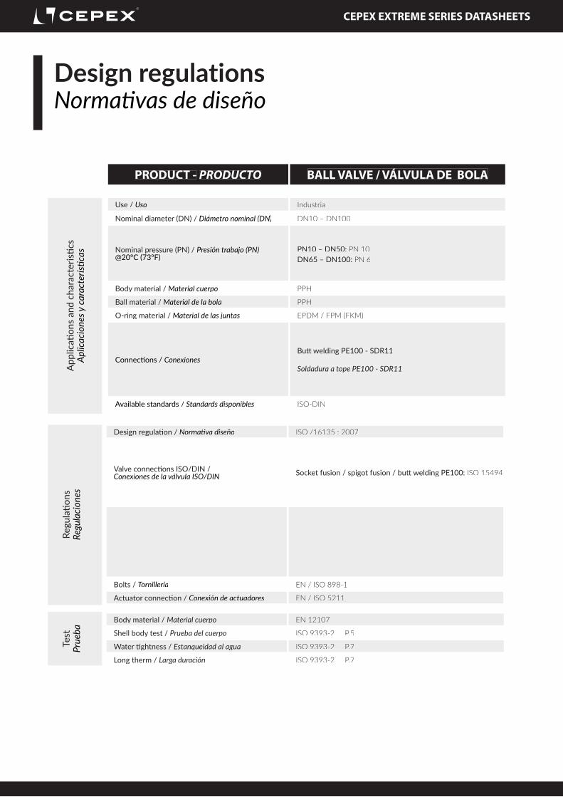
Nominal pressure (PN) / Presión trabajo (PN) @20ºC (73ºF)
PN10 – DN50: PN 10DN65 – DN100: PN 6
Body material / Material cuerpo PPH
Ball material / Material de la bola PPH
O-ring material / Material de las juntas EPDM / FPM (FKM)
Connecti ons / ConexionesButt welding PE100 - SDR11
Soldadura a tope PE100 - SDR11
Available standards / Standards disponibles ISO-DIN
Design regulati on / Normati va diseño ISO /16135 : 2007
Valve connecti ons ISO/DIN / Conexiones de la válvula ISO/DIN Socket fusion / spigot fusion / butt welding PE100: ISO 15494
Bolts / Tornillería EN / ISO 898-1
Actuator connecti on / Conexión de actuadores EN / ISO 5211
Body material / Material cuerpo EN 12107
Shell body test / Prueba del cuerpo ISO 9393-2 P.5
Water ti ghtness / Estanqueidad al agua ISO 9393-2 P.7
Long therm / Larga duración ISO 9393-2 P.7
CEPEX EXTREME SERIES DATASHEETS
Graphics ball valvesGráficas válvulas de bola
DN 20
DN 25
DN 32
DN 40
DN 50
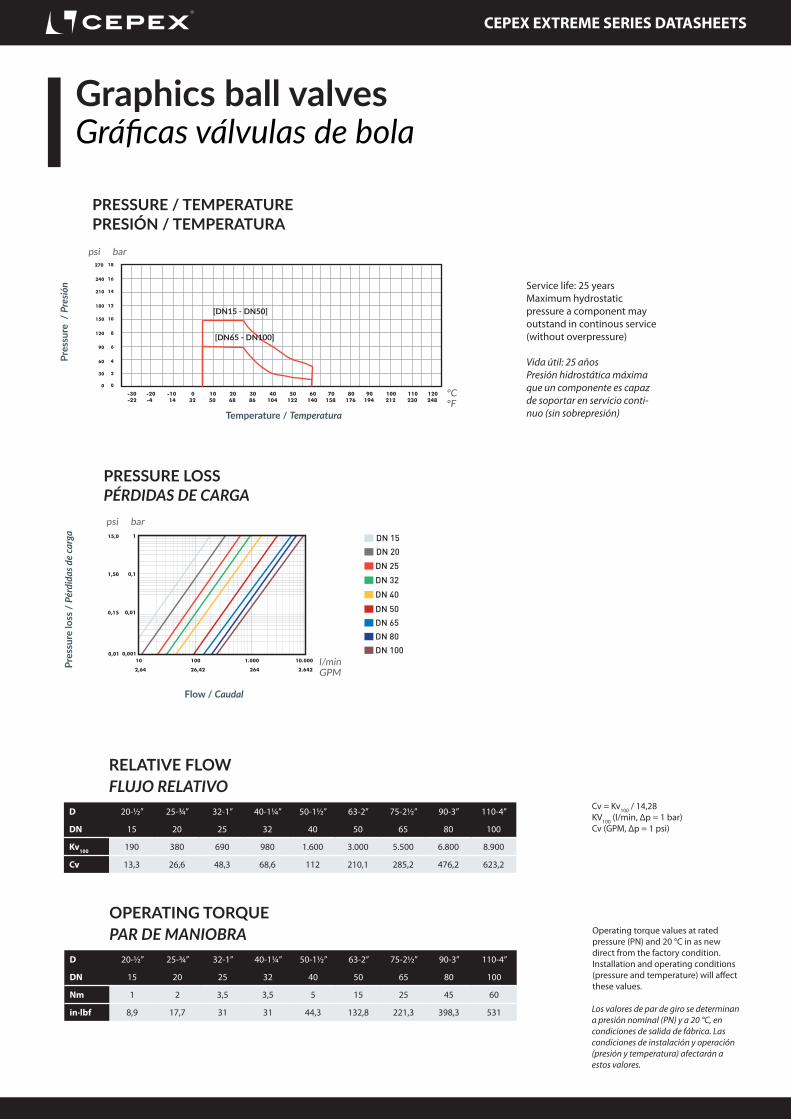
PRESSURE LOSSPÉRDIDAS DE CARGA
Pres
sure
loss
/ P
érdi
das d
e ca
rga
Flow / Caudal
DN 65DN 80DN 100
DN 15
psi bar
l/minGPM
PRESSURE / TEMPERATUREPRESIÓN / TEMPERATURA
Pres
sure
/ P
resió
n
Temperature / Temperatura
psi bar
ºCºF
OPERATING TORQUEPAR DE MANIOBRA
D 20-½” 25-¾” 32-1” 40-1¼” 50-1½” 63-2” 75-2½” 90-3” 110-4”
DN 15 20 25 32 40 50 65 80 100
Nm 1 2 3,5 3,5 5 15 25 45 60
in·lbf 8,9 17,7 31 31 44,3 132,8 221,3 398,3 531
Vida útil: 25 añosPresión hidrostática máxima que un componente es capaz de soportar en servicio conti-nuo (sin sobrepresión)
Service life: 25 yearsMaximum hydrostatic pressure a component may outstand in continous service (without overpressure)
Operating torque values at rated pressure (PN) and 20 °C in as new direct from the factory condition. Installation and operating conditions (pressure and temperature) will affect these values.
Los valores de par de giro se determinan a presión nominal (PN) y a 20 °C, en condiciones de salida de fábrica. Las condiciones de instalación y operación (presión y temperatura) afectarán a estos valores.
RELATIVE FLOWFLUJO RELATIVO
D 20-½” 25-¾” 32-1” 40-1¼” 50-1½” 63-2” 75-2½” 90-3” 110-4”
End connector o-ring / Junta manguitoEPDM Perox. | FPM (FKM)
Seal-carrier / PortajuntasPP-H
Dampener seal / junta amorti guaciónEPDM Perox. | FPM (FKM)
Inserts / insertosStainless steel AISI-303
Coupling bush / conexiónAluminum
Mounti ng clamp / soporte actuaciónPVC-U
Screws / tornilleríaDIN-912 - SS AISI-304
CEPEX EXTREME SERIES DATASHEETS
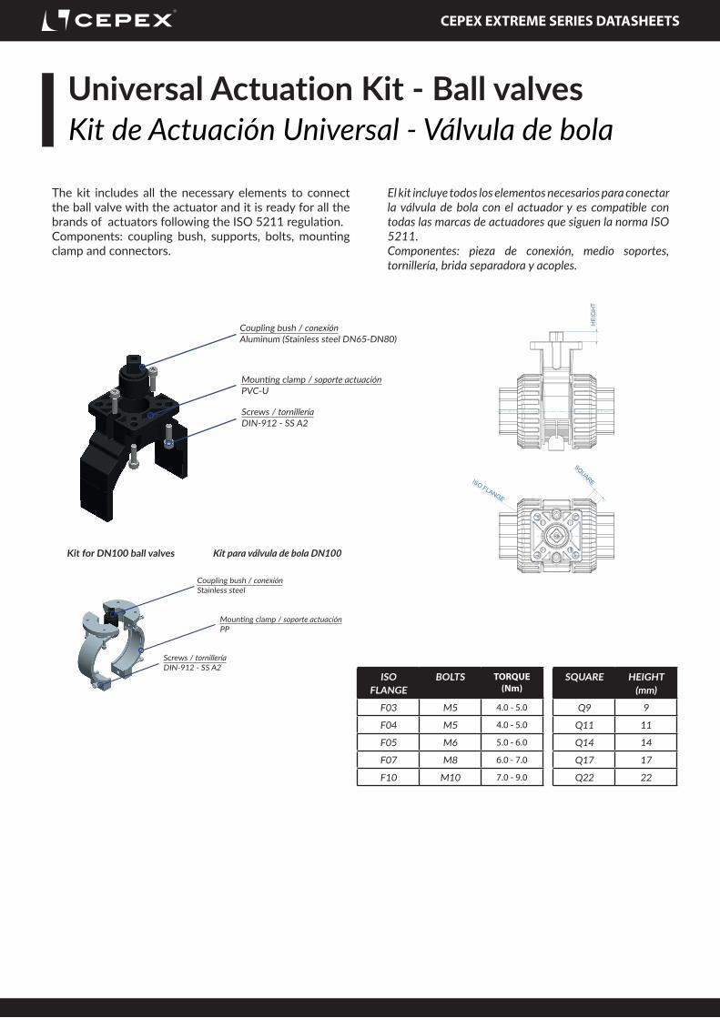
Coupling bush / conexiónAluminum (Stainless steel DN65-DN80)
Mounti ng clamp / soporte actuaciónPVC-U
Screws / tornilleríaDIN-912 - SS A2
Universal Actuation Kit - Ball valvesKit de Actuación Universal - Válvula de bola
The kit includes all the necessary elements to connect the ball valve with the actuator and it is ready for all the brands of actuators following the ISO 5211 regulati on.Components: coupling bush, supports, bolts, mounti ng clamp and connectors.
El kit incluye todos los elementos necesarios para conectar la válvula de bola con el actuador y es compati ble con todas las marcas de actuadores que siguen la norma ISO 5211.Componentes: pieza de conexión, medio soportes, tornillería, brida separadora y acoples.
ISO FLANGE
BOLTS TORQUE (Nm)
F03 M5 4.0 - 5.0
F04 M5 4.0 - 5.0
F05 M6 5.0 - 6.0
F07 M8 6.0 - 7.0
F10 M10 7.0 - 9.0
SQUARE HEIGHT (mm)
Q9 9
Q11 11
Q14 14
Q17 17
Q22 22
ISO FLANGE
HE
IGH
T
SQUARE
Coupling bush / conexiónStainless steel
Mounti ng clamp / soporte actuaciónPP
Screws / tornilleríaDIN-912 - SS A2
Kit for DN100 ball valves Kit para válvula de bola DN100
PNEUMATIC ACTUATOR - SPRING RETURNACTUADOR NEUMÁTICO - SIMPLE EFECTO
Technical characteristicsCaracterísticas técnicas
D75 (2½”) - DN65 71875 GT75 DA 71785 GT92 K08
D90 (3”) - DN80 69341 GT75 DA 69342 GT110 K08
D110 (4”) - DN100 72287 GT83 DA 72287 GT118 K08
CEPEX EXTREME SERIES DATASHEETS
Installation and commissioningInstalación y puesta en servicio
Before commencing the installation process, be sure to read carefully all the specifications in the instrucions manual of the product box or in our website. For solvent or welded connections, ensure also that the parts to be connected are of the same material and that you are using the correct solvent or welding tools.
The valve is supplied assembled from the factory and the following steps should be followed for its installation:1. Check that you have the specific welding machines and the corresponding element to weld the end connector.2. Adjust the valve to the installation leaving the union nut Fig. 1 on the tube before gluing the end connector Fig. 2.3. Leave an exact distance between end connectors (Fig. 2), so that the body of the valve can be easily introduced, preventing it from being strained by both ends of the tubing.4. The union could be made using butt welding (plain wall agaisnt wall - SDR11) or electrofusion (outer surface of the pipe and inner surface of the socket).The welded unions PE100 are made taking into account the instructions of the welding tool used. It is possible to use a butt welding or electrofusion machine.
When using the inserts, take note of the dimensions of the screws.
Antes de iniciar el proceso de instalación, asegurese de leer detenidamente el manual de instrucciones contenido en la caja on en nuestra website.Para la fijación de la válvula, siga las recomendaciones de buenas prácticas de instalación disponibles en la web de Cepex, con especial atención a las dilataciones térmicas y en la alineación de los tubos.
La válvula se suministra montada de fábrica y se deben seguir los siguientes pasos para su instalación:1. Revisar que se dispone de la maquinaria específica y el elemento adecuado para realizar la soldadura del maguito de la válvula.2. Ajustar la válvula a la instalación dejando montada la tuerca Fig. 1 en el tubo antes de encolar o soldar el manguito Fig. 2.3. Dejar una distancia exacta entre los manguitos (Fig. 2), de manera que el cuerpo de la válvula pueda montarse fácilmente, evitando que quede deformado entre los dos extremos del tubo.4. La unión puede ser realizada a través de soldadura a tope (pared plana contra pared plana - SDR11) o electrofusión (superfície externa de la tubería con superfície interna del manguito).Las uniones soldadas PE100 deben realizarse siguiendo las instrucciones de la máquina de soldadura utilizada. Es posible utilizar máquina de soldadura a tope o de electrofusión
Este rango de válvulas permite la fijación de la válvula a una base utilizando los insertos roscados de la zona inferior del cuerpo de la válvula. Tener en cuenta la medida de los insertos y la profundidad del tornillo.
1 2
43
5
BUTT WELDINGSOLDADURA A TOPE
ELECTROFUSIONELECTROFUSIÓN
CEPEX EXTREME SERIES DATASHEETS
Fig. 12 Fig. 1412
106 9 8
2 9
Fig. 15
Fig. 13
1
7Fig. 16
Fig. 17
Fig. 18
Operation and maintenance instructionsInstrucciones de operación y mantenimiento
If the valve is installed correctly pointing in the direction of flow marked on the body, it is possible to carry out the maintenance downstream without problems. By simply closing the valve this acts as a plug. If on the contrary it is upstream where maintenance is required, it is essential that there is no pressure in the circuit when dismantling the union nut and end connector.The operations described next are always carried out without fluid in the line.The valve is adjusted in the factory for correct and prolonged functioning. Nevertheless, it is possible to readjust the tightening of the sealing gasket on the ball when the conditions of use so require it.This operation is carried out with the help of the supplied tool (Fig. 18).1. Dismantle the valve’s union nuts (3) and remove them from their housing. 2. Put the outil into the slot that is found in the seal carriers for this purpose (12) and turn the key anti-clockwise to tighten the o-ring and clockwise to loosen it (Fig. 18). If any of the components of the valve wear out, you can replace them by dismantling the body of the valve. To do so, proceed in the same way with the adjustment but turn it clockwise until the seal carriers (12) are free. 3. When you have done this you may substitute any of the body’s O-rings (Fig. 13). 4. Turn the shaft until the ball is in a closed position; remove the ball (2) and remove the ball seat (9) (Fig. 14).5. To replace the shaft, it has to be forced as shown in Fig.16. Once the shaft has been removed (1) the o-rings can be replaced (7) (Fig. 17).
Remember that excessive force on the seal carriers can affect the action which can damage the actual functioning of the valve.Assembly can be done by reversing the process but always taking the precaution of lubricating the o-rings with PTFE oil. Do not use grease or mineral oils that attack the material of the o-rings.
Si la válvula está montada en el sentido correcto de la flecha marcada en el cuerpo de la válvula, es posible realizar el mantenimiento aguas abajo sin problemas. Cerrando simplemente la válvula, ésta actúa como tapón. Si por el contrario es necesario realizar un matenimiento aguas arriba de la válvula, es imprescindible que no haya presión en la línea antes de desmontar la tuerca y el manguito.Las operaciones descritas a continuación deben ser realizadas sin fluido en la línea.La válvula está ajustada desde fábrica para su funcionamiento correcto y prolongado. En todo caso, es posible que sea necesario reajustar el apriete del portajuntas contra la bola cuando las condiciones de uso lo requieran.Esta operación debe realizarse con la ayuda del útil previsto (Fig. 18).1. Desmontar las tuercas de unión y alejarla. 2. Colocar el útil en la ranura del portajuntas prevista para ello (12) y girar el útil en sentido antihorario para conseguir mayor apriete o en sentido horario para aflojarlo (Fig. 18). Si alguno de los componentes de la válvula estubiera en mal estado, reemplazarlo desmontando previamente el portajuntas del cuerpo de la válvula. Para ello, proceder de la misma manera que para ajustar el apriete del portajuntas, pero aflojando el portajuntas (12) en sentido horario hasta que quede libre. 3. Una vez desmontado, se puede sustituir cualquiera de las juntas tóricas (Fig. 13): 4. Girar el eje de la válvula a la posición de cerrado; extraer la bola (2) y el asiento (9) (Fig. 14).5. Para extraer el eje (1), empujar tal y como se muestra en la Fig.16. Una vez el eje esté desmontado sustituir las juntas tóricas del eje (7) (Fig. 17).
Es necesario recordar que un apriete excesivo del portajuntas puede afectar al funcionamiento correcto de la válvula.El montaje del conjunto debe realizarse en sentido inverso a lo descrito anteriormente, teniendo en cuenta que es necesario lubricar las juntas tóricas con aceite de PTFE. Es importante no usar grasas o aceites minerales que ataquen a las juntas o al material de la válvula.
CEPEX EXTREME SERIES DATASHEETS
Mount and dismantle the actuatorMontaje y desmontaje del actuador
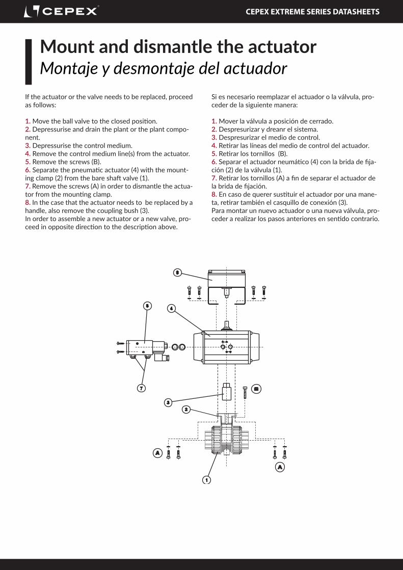
If the actuator or the valve needs to be replaced, proceed as follows:
1. Move the ball valve to the closed position.2. Depressurise and drain the plant or the plant compo-nent.3. Depressurise the control medium.4. Remove the control medium line(s) from the actuator.5. Remove the screws (B).6. Separate the pneumatic actuator (4) with the mount-ing clamp (2) from the bare shaft valve (1).7. Remove the screws (A) in order to dismantle the actua-tor from the mounting clamp.8. In the case that the actuator needs to be replaced by a handle, also remove the coupling bush (3).In order to assemble a new actuator or a new valve, pro-ceed in opposite direction to the description above.
Si es necesario reemplazar el actuador o la válvula, pro-ceder de la siguiente manera:
1. Mover la válvula a posición de cerrado.2. Despresurizar y dreanr el sistema.3. Despresurizar el medio de control.4. Retirar las líneas del medio de control del actuador.5. Retirar los tornillos (B).6. Separar el actuador neumático (4) con la brida de fija-ción (2) de la válvula (1).7. Retirar los tornillos (A) a fin de separar el actuador de la brida de fijación.8. En caso de querer sustituir el actuador por una mane-ta, retirar también el casquillo de conexión (3).Para montar un nuevo actuador o una nueva válvula, pro-ceder a realizar los pasos anteriores en sentido contrario.
CEPEX EXTREME SERIES DATASHEETS
TroubleshootingSolución de problemas
FAULT POSSIBLE CAUSE FAULT CLEARANCELeackage on the body of the valve Wear of the body o’ring Change the o’ring
Looseness of the seal carrier Adjust the seal carrierPresence of solids or strange elements Remove the valve and replace damaged
partsNuts under-tight Adjust the nutsEnd connector o-rings in wrong position Dissassemble the end connectors and
replace the o-ringsLeackage on the shaft of the valve Wear of the shaft o’rings Change the o’ringsThe torque is too strong or the valve is blocked
The seal carrier is over-tight Adjust the seal carrier
Valve leakage in low pressure The seal carrier is under-tight Adjust the seal carrierThe valve does not open or close. Lack of pressured air. Check air supply to actuatorThe valve does not close completely. The actuator stroke is not properly
adjusted to the valve.Check adjustment limits according to the actuator manual.
The torque of the valve has increased above the calculated value.
Check the valve: obstructions in the disc or malfunction of the valve.
The valve does not change the position. The solenoid valve does not operate properly due to the use of unfiltered air.
Add filtration equipment to the air supply input.
The solenoid does not work properly due to impurities or oxidation by a corrosive environment.
Change the solenoid valve and ask the technical department about the most appropriate solenoid valve.
PROBLEMA POSIBLE CAUSA SOLUCIÓNLa vávula fuga por el cuerpo Deterioro de la junta del cuerpo Cambiar junta
Falta de apriete del portajuntas Ajustar aprietePresencia de sólidos o elementos extraños Desmontar la válvula y cambiar los
elementos deterioradosTuercas no suficientemente apretadas Ajustar aprieteJuntas de manguito mal posicionadas Desmontar manguitos y reposicionar/
cambiar juntasLa válvula fuga por el eje Deterioro de las juntas del eje Cambiar juntasEl par de la válvula es excesivo o está bloqueada
Excesivo apriete del portajuntas Ajustar apriete
La válvula fuga en bajas presiones No suficiente apriete del portajuntas Ajustar aprieteLa válvula no abre o no cierra. Falta de presión de aire. Comprobar el suministro de aire al actuador.La válvula no cierra completamente. El par del actuador no está bien ajustado
con el de la válvula.Comprobar los ajustes de acuerdo con el manual del actuador.
El par de la válvula ha crecido por encima del valor calculado.
Comprobar la válvula: obstrucciones en la bola o mal funcionamiento.
La válvula no cambia de posición. La válvula solenoide no funciona correctamente debido al uso de aire no filtrado.
Añadir un equipo de filtración a la entrada de suministro de aire.
El solenoide no funciona correctamente debido a impurezas o oxidación por un ambiente corrosivo.
Cambiar la válvula solenoide y preguntar al departamento técnico sobre la válvula solenoide más apropiada.
CEPEX EXTREME SERIES DATASHEETS
Certificate of compliance pressure equipmentCertificado de conformidad equipos a presión
CEPEX EXTREME SERIES DATASHEETS
Certificate of compliance pressure equipmentCertificado de conformidad equipos a presión
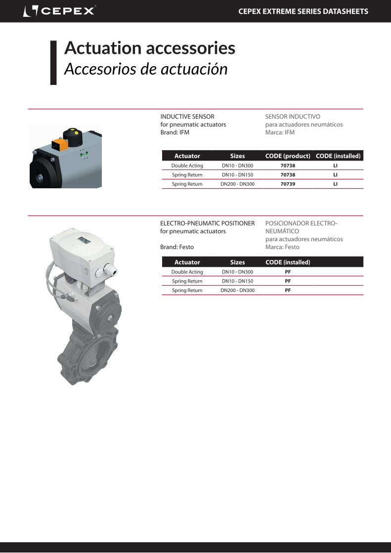
Actuation accessoriesAccesorios de actuación
NAMUR SOLENOID VALVEfor pneumatic actuatorsConfiguration 3/2 or 5/2Brand: SMC
ELECTROVÁLVULA NAMURpara actuadores neumáticosConfiguración 3/2 o 5/2Marca: SMC
RELIEF REGULATORSfor pneumatic actuators
REGULADORES DE ESCAPEpara actuadores neumáticos
Voltage CODE (product) CODE (installed)3/2 - 24 VAC 70734 S
3/2 - 24 VDC 70729 S
3/2 - 220 VAC 70731 S
5/2 - 24 VAC 70732 S
5/2 - 24 VDC 70733 S
5/2 - 220 VAC 70375 S
CODE (product)1 UNIT - 1 UNIDAD (solenoid 3/2) 70735