20
PPPL ST-FNSF Engineering Design Details Tom Brown TOFE Conference November 10, 2014
| Date post: | 14-Dec-2015 |
| Category: |
Documents |
| Upload: | yvette-davidge |
| View: | 216 times |
| Download: | 0 times |
PPPL ST-FNSFEngineering Design Details
Tom Brown
TOFE Conference
November 10, 2014

2
Some suggest to move from ITER by constructing a prototypical demonstration device (DEMO) that precedes a power plant; others
Define a smaller scale “Pilot Plant” that generates net electricity Qeng ≥ 1 as quickly as possible before building DEMO and
Some suggest that prior to building a DEMO device or Pilot Plant, it would be best to first operate a smaller Fusion Nuclear Science Facility (FNSF) to develop the blanket technology used for thermal power conversion and tritium breeding.
A number of roadmaps have been prescribed that lead to a fusion power plant from ITER
Fusion Roadmaps
ANS 2014 Winter Meeting and embedded topical meeting
3ANS 2014 Winter Meeting and embedded topical meeting
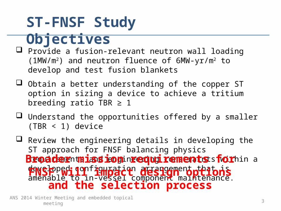
ST-FNSF Study Objectives
Provide a fusion-relevant neutron wall loading (1MW/m2) and neutron fluence of 6MW-yr/m2 to develop and test fusion blankets
Obtain a better understanding of the copper ST option in sizing a device to achieve a tritium breeding ratio TBR ≥ 1
Understand the opportunities offered by a smaller (TBR < 1) device
Review the engineering details in developing the ST approach for FNSF balancing physics requirements and engineering constraints within a developed configuration arrangement that is amenable to in-vessel component maintenance.
Broader mission requirements for FNSF will impact design options and the selection process

4
ITER
Device parameters: 4m, 6T B0
Double-null divertor Qengr ≥ 1 Steady-state T self-sufficient with TBR ≥1 DEMO blankets and divertors Power plant prototyped RM
AT-Pilot Plant S/C magnets
ST-FNSF
Device size: 1 - 1.7m, Double-null divertor Steady-state TBR: 0.88 to 1 DEMO blankets and divertors
K-DEMO
ANS 2014 Winter Meeting and embedded topical meeting
Fusion Roadmap options
5
Significant progress has been made in ST-FNSF Studies
Ex-vessel PF coils have been arranged to form a Super-X /snowflake divertor that operate with low heat loads,
A credible vertical maintenance scheme was developed to gain access to internal blanket modules, and
Port cut-outs were defined to support NNBI yet left sufficient blanket material to generate high TBR values.
ANS 2014 Winter Meeting and embedded topical meeting
Progress made
6
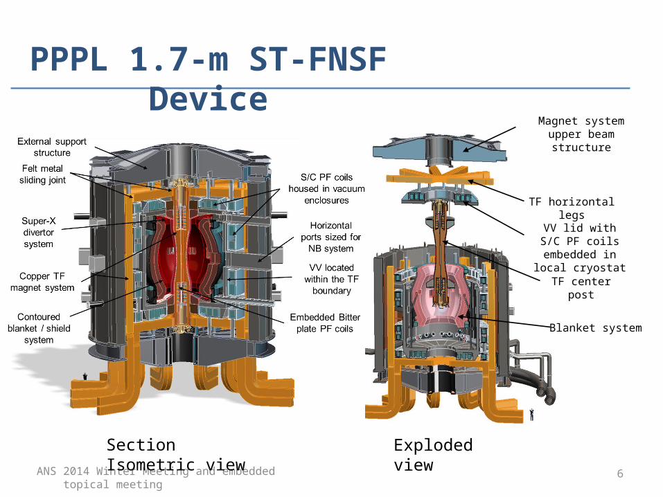
TF horizontal legs
Magnet system upper beam structure
Blanket system
VV lid with S/C PF coils embedded in
local cryostat
TF center post
ANS 2014 Winter Meeting and embedded topical meeting
PPPL 1.7-m ST-FNSF Device
Section Isometric view Exploded view
7ANS 2014 Winter Meeting and embedded topical meeting
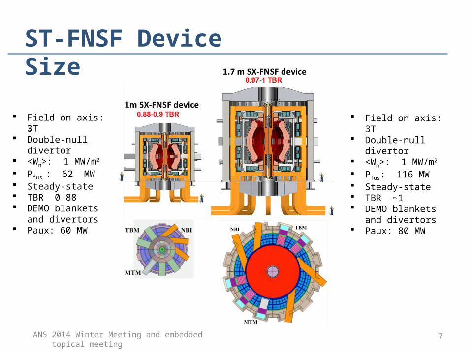
Field on axis: 3T Double-null divertor <Wn>: 1 MW/m2
Pfus: 116 MW Steady-state TBR ~1 DEMO blankets
and divertors Paux: 80 MW
ST-FNSF Device Size
Field on axis: 3T Double-null divertor <Wn>: 1 MW/m2
Pfus : 62 MW Steady-state TBR 0.88 DEMO blankets and
divertors Paux: 60 MW

8ANS 2014 Winter Meeting and embedded topical meeting
In-vessel details
MgO Cu Bitter plate PF pair located within TF center post
PF arrangement defines a Super-X/snowflake divertor
Double wall VV structure that contains tungsten carbide (WC) balls and borated water
External S/C PF coils contained in local cryostat
Plasma contoured outboard breeding blanket with local blanket above (below) divertor
Shielding sufficient to meet operation at 6 FPY
MgO Cu Bitter plate PF coils

9ANS 2014 Winter Meeting and embedded topical meeting
Reduced divertor heat load
The projected Super-X/snowflake divertor peak heat flux can be reduced by up to a factor of 3 relative to a conventional divertor to ≤ 10MW/m2 even for nominally attached conditions for surface-average neutron wall loading Wn = 1MW/m2.
The ability to operate with a Super-X/snowflake divertor places higher requirements on the PF system – more coils operating at higher currents, for coils located a distance from the plasma.
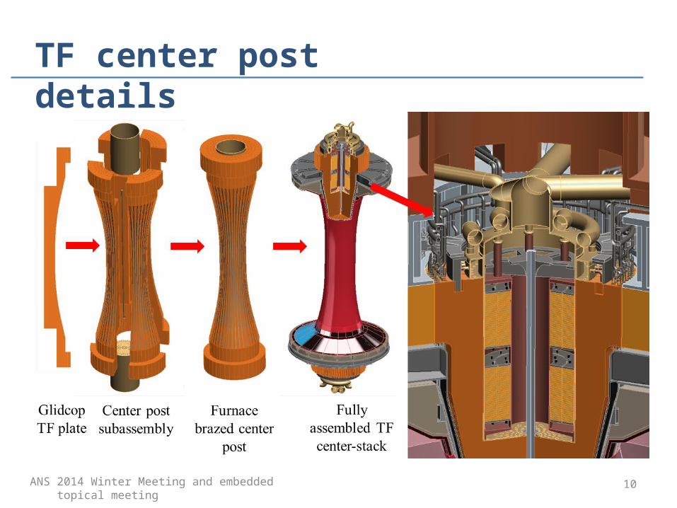
10ANS 2014 Winter Meeting and embedded topical meeting
TF center post details

11ANS 2014 Winter Meeting and embedded topical meeting
Impact of solenoid free start-upDesign features were added to a DCLL blanket segment to support the requirements of a coaxial Helicity injection (CHI) start-up scenario
12ANS 2014 Winter Meeting and embedded topical meeting
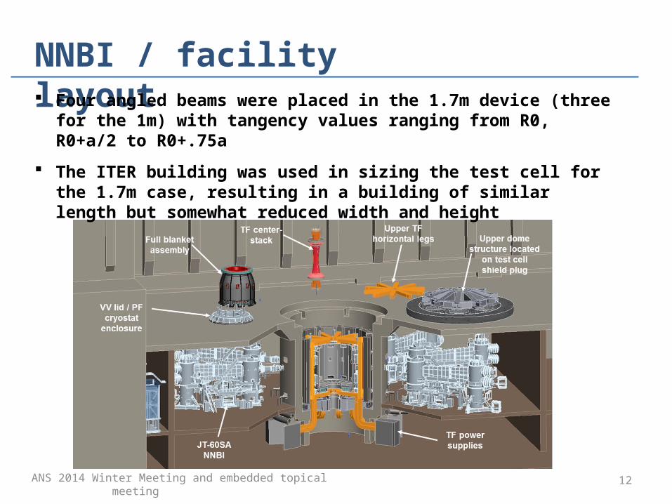
NNBI / facility layout Four angled beams were placed in the 1.7m device (three for the 1m)
with tangency values ranging from R0, R0+a/2 to R0+.75a
The ITER building was used in sizing the test cell for the 1.7m case, resulting in a building of similar length but somewhat reduced width and height

13ANS 2014 Winter Meeting and embedded topical meeting
TF power suppliesA 86m wide by 162m long single floor building was needed to locate an arrangement of twenty-four 1 MA units each comprising four groups of ABB 250 KA power supplies.
A high cost penalty results unless more compact low-voltage / high-current power supply technology can be developed such as a homopolar generator.

14
High Temperature Superconductor (HTS) ST Pilot Plant design was developed*
* Developed under a contract with Tokamak Energy (UK)
• 1.8 aspect ratio, 1.4m R0, 3.2T B0
• Pfusion ~ 100MW, QDT ~ 10• PF coils configured for a Super-
X/snowflake divertor • negative neutral beam injection
for heating and current drive
A 2.35m HTS-ST device has been developed with 0.5m of inboard shield.
To expand ST DEMO operations and evaluate possible FNSF feasibility, high temperature S/C options are being investigated

15ANS 2014 Winter Meeting and embedded topical meeting
CONCLUSIONS
Significant progress was made within the ST-FNSF study these past few years to develop physics, engineering and neutronics details to enhance the selection process of an FNSF program.
Two ST-FNSF designs developed support ex-vessel PF coils to form a Super-X/snowflake divertor that operate with low heat loads, a credible vertical maintenance scheme and an internal arrangement of blanket modules that provide proper port cut-outs to support NNBI yet leave sufficient blanket material to generate high TBR values.
The study found that for a copper TF device, 1.7m was the threshold major radius to operate with a TBR ~ 1and that a device sized at 1m could provide sufficiently high tritium breeding with lower capital and operating cost.

16ANS 2014 Winter Meeting and embedded topical meeting
CONCLUSIONS (cont.)
The 1.7m device size and power supply details make it less favorable when compared to other potential FNSF options; the 1m design appears to be a more cost attractive approach that should be further evaluated.
The HTS ST design was found to have merit in defining a feasible ST power plant and should be pursued to see if it fits within the expectations of an FNSF mission.
ANS 2014 Winter Meeting and embedded topical meeting
17
BACK UP SLIDES
18
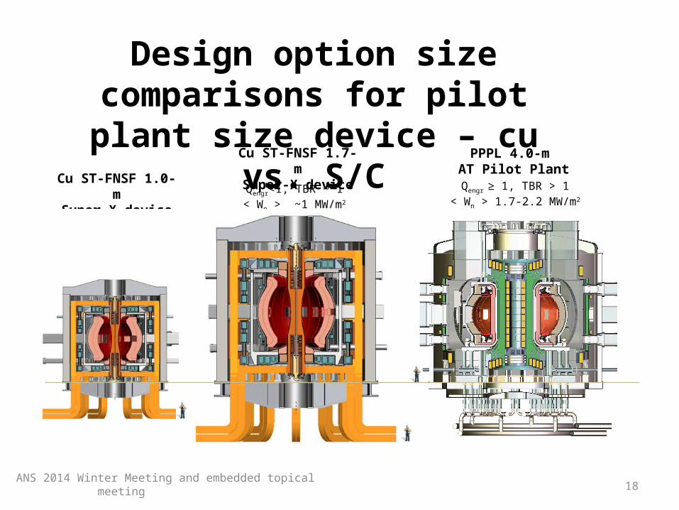
PPPL 4.0-m AT Pilot PlantQengr ≥ 1, TBR > 1
< Wn > 1.7-2.2 MW/m2
Qengr<1, TBR ~ 1< Wn > ~1 MW/m2
Cu ST-FNSF 1.7-mSuper-X device
Design option size comparisons for pilot plant size device – cu vs. S/C
ANS 2014 Winter Meeting and embedded topical meeting
Qengr <1, TBR < 1< Wn > ~1 MW/m2
Cu ST-FNSF 1.0-mSuper-X device

19
PPPL 4.0-m AT Pilot Plant
Qengr ~1, TBR < 1< Wn > ~1 MW/m2
Qengr ≥ 1, TBR > 1< Wn > 1.7-2.2 MW/m2
TE 1.4-mHTS ST-FNSF
Super-X device
PPPL 2.35-m HTS ST-FNSF
Super-X design
Qengr ≥ 1, TBR > 1360 MW fusion power
Design option size comparisons for pilot plant size with S/C magnets
ANS 2014 Winter Meeting and embedded topical meeting

20
PPPL 4.0-m AT Pilot Plant
Qengr ≥ 1, TBR > 1< Wn > 1.7-2.2 MW/m2
510-647 MW fusion power
K-DEMO 6.8-m device
Pelec ~ 200-600 MW, TBR > 1< Wn > 2.09 MW/m2
On the road to Demo - size comparisons with S/C magnets
PPPL 2.35-m HTS ST-FNSF design
Qengr ≥ 1, TBR > 1360 MW fusion power
ANS 2014 Winter Meeting and embedded topical meeting


![@)#! ; fnsf ] ltJjtL vDkf lgz:qLs /0f cleofg](https://static.documents.pub/doc/80x56/56815e05550346895dcc4f9b/-fnsf-ltjjtl-vdkf-lgzqls-0f-cleofg.jpg)


