13
India Ki Waterline PPR PIPES & FITTINGS High Performance Piping System

India Ki Waterline
PPR PIPES & FITTINGSHigh Performance Piping System

About Us
A progressive development of civilization results
in people aspiring for better living standards,
which can be met by using upgraded high quality
material in the products offered by the
manufacturing companies. In the building
industry, we do our bit by manufacturing
products which are a better fit for use as well as
more aesthetic than the traditional ones.
Today, the use of plastic products is prevalent in
construction as well as other industries.
Constant changes in plastic raw material and
processing techniques provide advantages
which make these a preferred material over
tradit ional construct ion and industr ia l
application material. One of these innovations is
plumbing pipes and fittings produced from
Polypropylene Random Copolymer (PPRC or
commonly known as PPR) material.
The superior physical characteristics of PPR - such as having a working temperature from -20° up to 95° celsius along with excellent chemical resistance, providing a definite solution to oxidation and calcification; make PPR an ideal material - primarily for chemical transportation, in pharmaceutical companies and for other industrial use, as well as, hot & cold water plumbing systems in buildings and industrial piping.
Vectus has been a leading manufacturer of uPVC Piping Systems since last 2 decades. Based on the needs of its customers, Vectus started manufacturing of pipes, fittings & valves from PPR material using the best available technology and raw material. Yet again, Vectus is proud to offer a complete range of high quality and reliable PPR Piping Systems for the modern construction industry.
Vectus Industries Limited is one of the leading
Polymer Based Water Solution companies in India;
primarily in the business of manufacturing water
storage tanks and pipes for more than two decades
now.
We laid our foundation with the manufacturing of
products such as Rotational Moulded Tanks, PPR
Piping Systems, PVC Pressure Piping Systems, Multi-
Layer Composite Piping Systems, SWR Drainage
Systems, uPVC Column Pipes, Casing Pipes, Agri
Pipes, Polyethylene Manholes and various kinds of
Plastic Moulded articles for agricultural and
household purposes.
In our quest for technological innovations, in the
year 2009, we introduced to the country - Blow
Moulded water storage tanks that are highly durable
and cost effective. We now have the distinction of
being one of the leading manufacturers of Blow
Moulded water storage tanks in the world.
With more than 3500 dealers, 10,000+ retail
counters, 14 manufacturing plants and 8 depots
across the country, Vectus has now become India's
leading and fastest growing Water Storage and
Piping System Company with a CAGR of 23%
(Financial Year 2012 to 2018).
Vectus Industries Limited is an ISO 9001:2008
Certified Company and also signed a technical
collaboration with Flotek of Turkey recently, for
manufacturing PE Manholes in India. These
manholes are made as per EN 13598 - 2 standards
and are widely used for infrastructure requirements
around the globe.
We were the first in the category to launch a one-
stop application for all needs of the market. For
integrating this app with our SAP S/4 Hana Module,
Vectus Industries Limited was given a special
recognition in the USA for making a change for social
cause.
The Preface
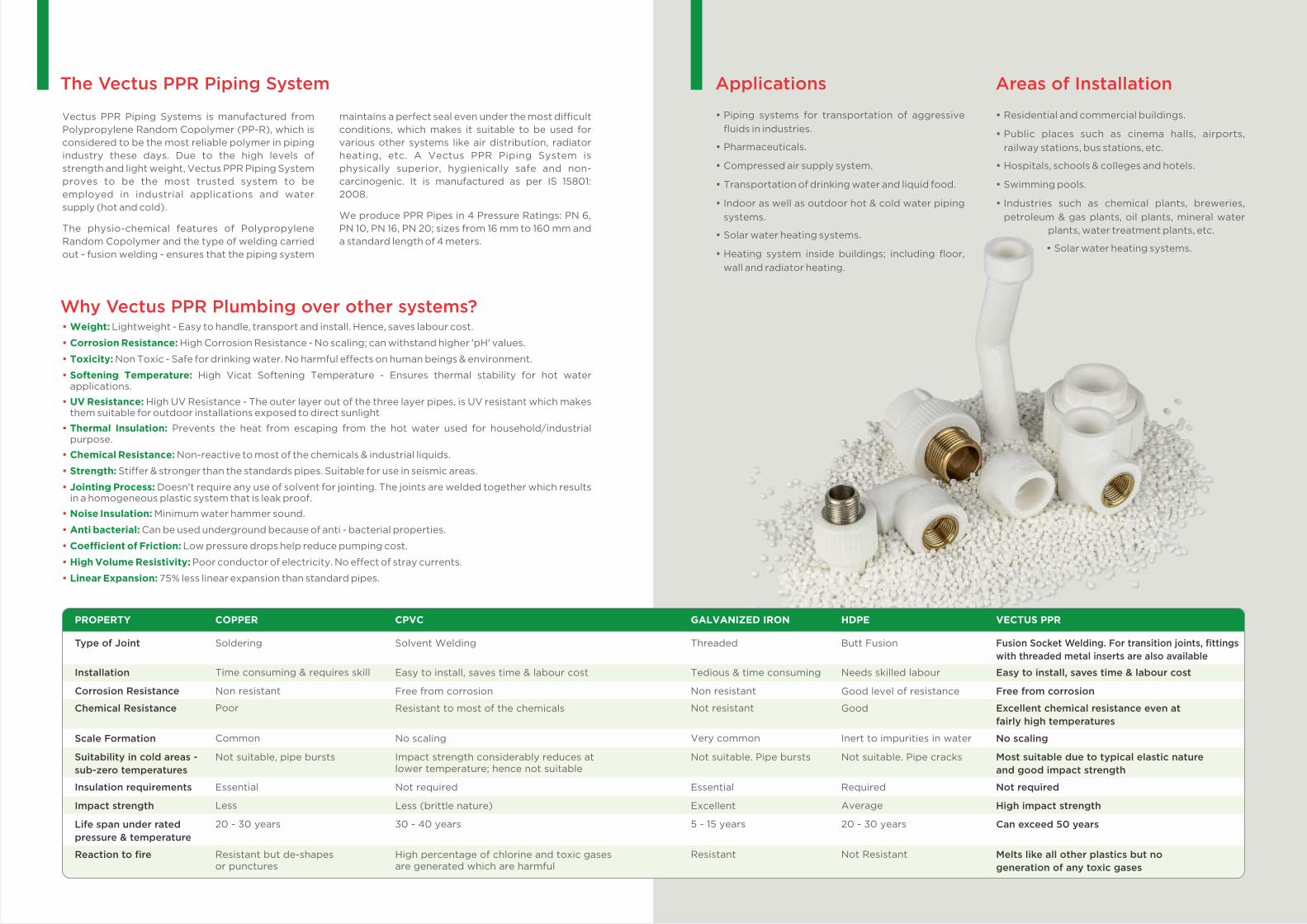
The Vectus PPR Piping System
Vectus PPR Piping Systems is manufactured from
Polypropylene Random Copolymer (PP-R), which is
considered to be the most reliable polymer in piping
industry these days. Due to the high levels of
strength and light weight, Vectus PPR Piping System
proves to be the most trusted system to be
employed in industrial applications and water
supply (hot and cold).
The physio-chemical features of Polypropylene
Random Copolymer and the type of welding carried
out - fusion welding - ensures that the piping system
maintains a perfect seal even under the most difficult
conditions, which makes it suitable to be used for
various other systems like air distribution, radiator
heating, etc. A Vectus PPR Piping System is
physically superior, hygienically safe and non-
carcinogenic. It is manufactured as per IS 15801:
2008.
We produce PPR Pipes in 4 Pressure Ratings: PN 6,
PN 10, PN 16, PN 20; sizes from 16 mm to 160 mm and
a standard length of 4 meters.
Ÿ Weight: Lightweight - Easy to handle, transport and install. Hence, saves labour cost.
Ÿ Corrosion Resistance: High Corrosion Resistance - No scaling; can withstand higher 'pH' values.
Ÿ Toxicity: Non Toxic - Safe for drinking water. No harmful effects on human beings & environment.
Ÿ Softening Temperature: High Vicat Softening Temperature - Ensures thermal stability for hot water applications.
Ÿ UV Resistance: High UV Resistance - The outer layer out of the three layer pipes, is UV resistant which makes them suitable for outdoor installations exposed to direct sunlight
Ÿ Thermal Insulation: Prevents the heat from escaping from the hot water used for household/industrial purpose.
Ÿ Chemical Resistance: Non-reactive to most of the chemicals & industrial liquids.
Ÿ Strength: Stiffer & stronger than the standards pipes. Suitable for use in seismic areas.
Ÿ Jointing Process: Doesn't require any use of solvent for jointing. The joints are welded together which results in a homogeneous plastic system that is leak proof.
Ÿ Noise Insulation: Minimum water hammer sound.
Ÿ Anti bacterial: Can be used underground because of anti - bacterial properties.
Ÿ Coefficient of Friction: Low pressure drops help reduce pumping cost.
Ÿ High Volume Resistivity: Poor conductor of electricity. No effect of stray currents.
Ÿ Linear Expansion: 75% less linear expansion than standard pipes.
Why Vectus PPR Plumbing over other systems?
Installation Time consuming & requires skill Easy to install, saves time & labour cost Tedious & time consuming Needs skilled labour Easy to install, saves time & labour cost
Corrosion Resistance Non resistant Free from corrosion Non resistant Good level of resistance Free from corrosion
Chemical Resistance Poor Resistant to most of the chemicals Not resistant Good Excellent chemical resistance even at fairly high temperatures
Scale Formation Common No scaling Very common Inert to impurities in water No scaling
Suitability in cold areas - sub-zero temperatures
Not suitable, pipe bursts Impact strength considerably reduces at lower temperature; hence not suitable
Not suitable. Pipe bursts Not suitable. Pipe cracks Most suitable due to typical elastic nature and good impact strength
Insulation requirements Essential Not required Essential Required Not required
Impact strength Less Less (brittle nature) Excellent Average High impact strength
Life span under rated pressure & temperature
20 - 30 years 30 - 40 years 5 - 15 years 20 - 30 years Can exceed 50 years
Reaction to fire Resistant but de-shapes or punctures
High percentage of chlorine and toxic gases are generated which are harmful
Resistant Not Resistant Melts like all other plastics but no generation of any toxic gases
PROPERTY COPPER CPVC GALVANIZED IRON HDPE VECTUS PPR
Type of Joint Soldering Solvent Welding Threaded Butt Fusion Fusion Socket Welding. For transition joints, fittings with threaded metal inserts are also available
Ÿ Piping systems for transportation of aggressive
fluids in industries.
Ÿ Pharmaceuticals.
Ÿ Compressed air supply system.
Ÿ Transportation of drinking water and liquid food.
Ÿ Indoor as well as outdoor hot & cold water piping
systems.
Ÿ Solar water heating systems.
Ÿ Heating system inside buildings; including floor,
wall and radiator heating.
Applications Areas of Installation
Ÿ Residential and commercial buildings.
Ÿ Public places such as cinema halls, airports,
railway stations, bus stations, etc.
Ÿ Hospitals, schools & colleges and hotels.
Ÿ Swimming pools.
Ÿ Industries such as chemical plants, breweries,
petroleum & gas plants, oil plants, mineral water
plants, water treatment plants, etc.
Ÿ Solar water heating systems.

Specifications and Properties
Thermal PropertiesPROPERTY
Thermal Conductivity
Specific Heat at 23°C
Coefficient of Linear Expansion
VICAT Softening Temperature
Melting Temperature Range
TEST METHOD
DIN 52612
Calorimeter
DIN 53752
ISO 306
ISO 3146
UNITS
W/m.k
KJ/Kg.K
mm/M°C
°C
°C
VALUE
0.24
2.0
1.5 X 10⁻⁴
132
140 - 150
TEST METHOD
ISO 527 - 1,2
ISO 527 - 1,2
ISO 527 - 1,2
ASTM D 790
ISO 527
ISO 527
DIN 53 505
-
ISO179/leU
ISO179/leU
ISO179/leU
UNITS
Mpa
%
Mpa
Mpa
Mpa
%
-
-
2KJ/m
2KJ/m
2KJ/m
VALUE
24
>50
850
850
40
800
65
0.007
22.0
4.0
2.5
PROPERTY
Tensile Stress at Yield (50mm/minute)
Tensile Strain at Yield (50mm/minute)
Tensile Modulus (secant)
Flexural Modulus
Tear Strength
Elongation at Tear
Shore D Hardness
Pipe Friction Factor
CHARPY Impact Strength +23°C
0°C
-30°C
Mechanical Properties
Electrical PropertiesDi Electric Constant
Volume Resistivity
Di Electric Strength
DIN 53483
DIN 53482
DIN 53481
-
Ohm-cm
KV/mm
2.3
>1 X 10¹⁶
?20
Admissible Operating PressurePIPE SERIES AS PER
DIN 8077 / 8078
35.0
33.2
32.1
31.1
30.3
29.5
30.0
28.1
27.3
26.5
25.7
24.9
25.5
23.9
23.1
22.3
21.8
21.2
21.5
20.2
19.6
18.8
18.3
17.8
27.8
26.4
25.5
24.7
24.0
23.4
23.8
22.3
21.7
21.1
20.4
19.8
20.2
19.0
18.3
17.7
17.3
16.9
17.1
16.0
15.6
15.0
14.5
14.1
17.6
16.6
16.1
15.6
15.2
14.8
15.0
14.1
13.7
13.3
12.9
12.5
12.8
12.0
11.6
11.2
10.9
10.6
10.8
10.1
9.8
9.4
9.2
8.9
1
5
10
25
50
100
1
5
10
25
50
100
1
5
10
25
50
100
1
5
10
25
50
100
10°C
20°C
30°C
40°C
SDR 6PN 20
SDR 7.4PN 16
SDR 11PN 10
Safety Factor - 1.5Normal Pressure for
PP-R Pipes (Kg/cm2)
ServiceLifein
Years
Temp.°C
PIPE SERIES AS PER DIN 8077 / 8078
18.3
17.0
16.5
15.9
15.4
14.9
15.4
14.3
13.8
13.3
12.7
13.0
11.9
11.7
10.1
8.5
10.9
9.6
8.0
6.4
7.7
5.0
(4.2)*
14.5
13.5
13.1
12.6
12.2
11.8
12.2
11.4
11.0
10.5
10.1
10.3
9.5
9.3
8.0
6.7
8.6
7.6
6.3
5.1
6.1
4.0
(3.4)*
9.2
8.5
8.2
8.0
7.7
7.4
7.7
7.2
6.9
6.7
6.4
6.5
6.0
5.9
5.1
4.3
5.5
4.8
4.0
3.2
3.9
2.5
(2.1)*
1
5
10
25
50
100
1
5
10
25
50
1
5
10
25
50
1
5
10
25
1
5
(10)*
50°C
60°C
70°C
80°C
95°C
SDR 6PN 20
SDR 7.4PN 16
SDR 11PN 10
Safety Factor - 1.5Normal Pressure for
PP-R Pipes (Kg/cm2)
ServiceLifein
Years
Temp.°C
*Bracketed values apply where testing can be shown to have been carried out for longer than 1000 hours at 95°C
Recommended application
Cold water installation Hot water installation Central heating installation
PROPERTY
Density at 27°C
Melt Flow Rate
at 230°C/5 Kg
TEST METHOD
IS 12235 (Part 14)
IS 13360 (Part 4 / Sec 1)
UNITS
Kg/m3
Gm/10 min
VALUE
900 - 910
< 0.50
Technical Specifications
Viscosity ISO 1191 • ISO 1628 T3
at 230°C/2.16 Kg
IS 13360 (Part 4 / Sec 1) Gm/10 min < 0.80
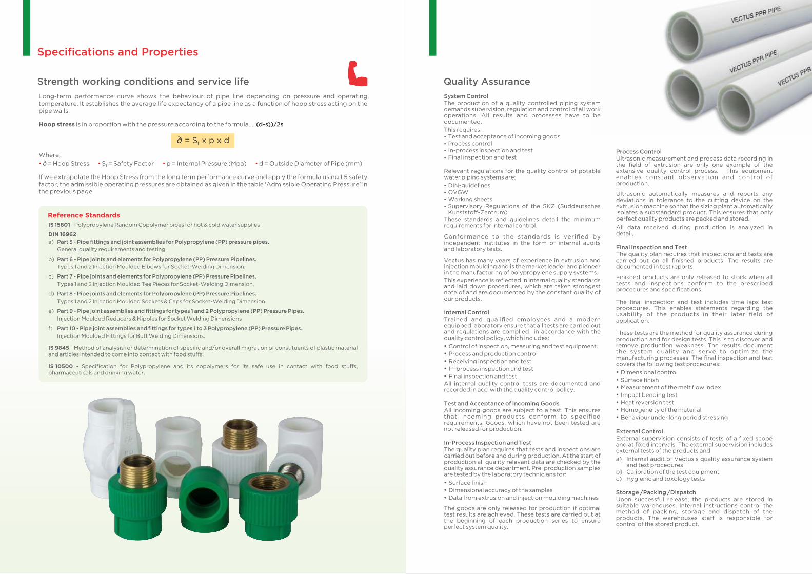
Long-term performance curve shows the behaviour of pipe line depending on pressure and operating temperature. It establishes the average life expectancy of a pipe line as a function of hoop stress acting on the pipe walls.
Hoop stress is in proportion with the pressure according to the formula... (d-s))/2s
∂ = S x p x df
Where,
• • • • ∂ = Hoop Stress S = Safety Factor p = Internal Pressure (Mpa) d = Outside Diameter of Pipe (mm)f
If we extrapolate the Hoop Stress from the long term performance curve and apply the formula using 1.5 safety factor, the admissible operating pressures are obtained as given in the table 'Admissible Operating Pressure' in the previous page.
Strength working conditions and service life
Specifications and Properties
IS 15801 - Polypropylene Random Copolymer pipes for hot & cold water supplies
DIN 16962
a) Part 5 - Pipe fittings and joint assemblies for Polypropylene (PP) pressure pipes. General quality requirements and testing.
b) Part 6 - Pipe joints and elements for Polypropylene (PP) Pressure Pipelines. Types 1 and 2 Injection Moulded Elbows for Socket-Welding Dimension.
c) Part 7 - Pipe joints and elements for Polypropylene (PP) Pressure Pipelines. Types 1 and 2 Injection Moulded Tee Pieces for Socket-Welding Dimension.
d) Part 8 - Pipe joints and elements for Polypropylene (PP) Pressure Pipelines. Types 1 and 2 Injection Moulded Sockets & Caps for Socket-Welding Dimension.
e) Part 9 - Pipe joint assemblies and fittings for types 1 and 2 Polypropylene (PP) Pressure Pipes. Injection Moulded Reducers & Nipples for Socket Welding Dimensions
f) Part 10 - Pipe joint assemblies and fittings for types 1 to 3 Polypropylene (PP) Pressure Pipes. Injection Moulded Fittings for Butt Welding Dimensions.
IS 9845 - Method of analysis for determination of specific and/or overall migration of constituents of plastic material and articles intended to come into contact with food stuffs.
IS 10500 - Specification for Polypropylene and its copolymers for its safe use in contact with food stuffs, .pharmaceuticals and drinking water.
Reference Standards
System ControlThe production of a quality controlled piping system demands supervision, regulation and control of all work operations. All results and processes have to be documented.
This requires:Ÿ Test and acceptance of incoming goodsŸ Process controlŸ In-process inspection and testŸ Final inspection and test
Relevant regulations for the quality control of potable water piping systems are:
Ÿ DIN-guidelinesŸ OVGWŸ Working sheetsŸ Supervisory Regulations of the SKZ (Suddeutsches
Kunststoff-Zentrum)These standards and guidelines detail the minimum requirements for internal control.
Conformance to the standards is verified by independent institutes in the form of internal audits and laboratory tests.
Vectus has many years of experience in extrusion and injection moulding and is the market leader and pioneer in the manufacturing of polypropylene supply systems.
This experience is reflected in internal quality standards and laid down procedures, which are taken strongest note of and are documented by the constant quality of our products.
Internal ControlTrained and qualified employees and a modern equipped laboratory ensure that all tests are carried out and regulations are complied in accordance with the quality control policy, which includes:
Ÿ Control of inspection, measuring and test equipment.
Ÿ Process and production control
Ÿ Receiving inspection and test
Ÿ In-process inspection and test
Ÿ Final inspection and testAll internal quality control tests are documented and recorded in acc. with the quality control policy. Test and Acceptance of Incoming GoodsAll incoming goods are subject to a test. This ensures that incoming products conform to specified requirements. Goods, which have not been tested are not released for production.
In-Process Inspection and TestThe quality plan requires that tests and inspections are carried out before and during production. At the start of production all quality relevant data are checked by the quality assurance department. Pre production samples are tested by the laboratory technicians for:
Ÿ Surface finish
Ÿ Dimensional accuracy of the samples
Ÿ Data from extrusion and injection moulding machines
The goods are only released for production if optimal test results are achieved. These tests are carried out at the beginning of each production series to ensure perfect system quality.
Process ControlUltrasonic measurement and process data recording in the field of extrusion are only one example of the extensive quality control process. This equipment enables constant observation and control of production.
Ultrasonic automatically measures and reports any deviations in tolerance to the cutting device on the extrusion machine so that the sizing plant automatically isolates a substandard product. This ensures that only perfect quality products are packed and stored.
All data received during production is analyzed in detail.
Final inspection and TestThe quality plan requires that inspections and tests are carried out on all finished products. The results are documented in test reports
Finished products are only released to stock when all tests and inspections conform to the prescribed procedures and specifications.
The final inspection and test includes time laps test procedures. This enables statements regarding the usability of the products in their later field of application.
These tests are the method for quality assurance during production and for design tests. This is to discover and remove production weakness. The results document the system quality and serve to optimize the manufacturing processes. The final inspection and test covers the following test procedures:
Ÿ Dimensional control
Ÿ Surface finish
Ÿ Measurement of the melt flow index
Ÿ Impact bending test
Ÿ Heat reversion test
Ÿ Homogeneity of the material
Ÿ Behaviour under long period stressing
External ControlExternal supervision consists of tests of a fixed scope and at fixed intervals. The external supervision includes external tests of the products and
a) Internal audit of Vectus's quality assurance system and test procedures
b) Calibration of the test equipmentc) Hygienic and toxology tests
Storage /Packing /DispatchUpon successful release, the products are stored in suitable warehouses. Internal instructions control the method of packing, storage and dispatch of the products. The warehouses staff is responsible for control of the stored product.
Quality Assurance
Mounting of the tools
1. Assemble and tighten the cold welding tools manually.
2. Before fusing distribution blocks, where two connections are welded at the same time, place the welding tool into the corresponding holes of the heating surface.
3. All welding tools must be free from impurities. Check if they are clean before assembling.
4. Place the welding tools on the welding device. Ensure that there is full surface contact between the welding tool and the heating surface.
5. Plug in the welding device. Depending on the ambient temperature, it takes 5-15 minutes to heat up the heating surface.
The heating up process is finished, when the temperature pilot light is switched on.
Heating up Phase
6. During the heating up phase tighten the welding tools carefully with the allan key.
Take care that the tools are completely on the heating surface. Never use pliers or any other unsuitable tools, as this will damage the coating of the welding tools.
0 7. The necessary temperature to weld Vectus PPR system is 260 C.
ATTENTION: First welding - two minutes after reaching the welding temperature!
Handling
8. A tool change on a heated device requires another check of the welding temperature at the new tool (after its heating up).
9. If the device has been unplugged, i.e. during longer breaks, the heating up process has to be restarted.
10. After use, unplug the welding device and let it cool down. Water must never be used to cool the welding device, as this would destroy the heating resistance.
11. Protect welding devices and tools against impurities. Burnt particles may lead to an incorrect fusion. The tools may be cleaned with cleansing cloths. Always keep the welding tools dry. If necessary, dry them with a clean, non fibrous tissue.
12. For perfect fusion, damaged or dirty welding tools must be replaced, as only impeccable tools grant a perfect connection.
13. Never attempt to open or repair a defective device. Send defective device for repair by a technician.
14. Check the operating temperature of welding devices regularly by means of suitable measuring instruments.
If necessary clean the welding tools with a non fibrous, coarse tissue and with methylated spirit.
The dimension above 125 mm are joined by Butt Welding.
0* Heating time recommended by Vectus at outdoor temperatures below +5 C.
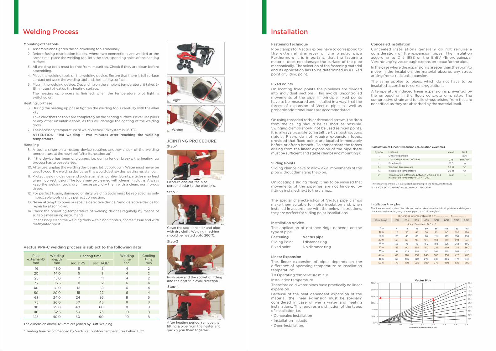
Right
Wrong
JOINTING PROCEDURE
Measure and cut the pipe perpendicular to the pipe axis.
Step-1
Clean the socket heater and pipe with dry cloth. Welding machine
Oshould be heated upto 260 C.
Step-2
Push pipe and the socket of fittinginto the heater in axial direction.
Step-3
After heating period, remove the fitting & pipe from the heater and quickly join them together.
Step-4
Pipe external-Ø
mm
Weldingtime sec.
Heating time Weldingdepth mm
Coolingtimeminsec. DVS sec. AQE*
2
2
2
4
4
4
6
8
8
8
8
Vectus PPR-C welding process is subject to the following data
4
4
4
6
6
6
8
8
8
10
5
5
7
8
12
18
24
30
40
50
60
8
8
11
12
18
27
36
45
60
75
90 10
13.0
14.0
15.0
16.5
18.0
20.0
24.0
26.0
29.0
32.5
40.0
16
20
25
32
40
50
63
75
90
110
125
Welding Process Installation
Fastening Technique
Pipe clamps for Vectus -pipes have to correspond to the external diameter of the plast ic pipe Furthermore it is important, that the fastening material does not damage the surface of the pipe mechanically. The selection of the fastening material and its application has to be determined as a Fixed point or Sliding point.
Fixed Points
On locating fixed points the pipelines are divided into individual sections. This avoids uncontrolled movements of the pipe. In principle, fixed points have to be measured and installed in a way, that the forces of expansion of Vectus pipes as well as probable additional loads are accommodated.
On using threaded rods or threaded screws, the drop from the ceiling should be as short as possible. Swinging clamps should not be used as fixed points. It is always possible to install vertical distributions rigidly. Risers do not require expansion loops, provided that fixed points are located immediately before or after a branch . To compensate the forces arising from the linear expansion of the pipe there must be sufficient and stable clamps and mountings.
Sliding Points
Sliding clamps have to allow axial movements of the pipe without damaging the pipe.
On locating a sliding clamp it has to be ensured that movements of the pipelines are not hindered by fittings installed next to the clamps.
The special characteristics of Vectus pipe clamps make them suitable for noise insulation and, when installed in accordance with the below instructions, they are perfect for sliding point installations.
Installation Advice
The application of distance rings depends on the type of pipe
Fastening Vectus pipe
Sliding Point 1 distance ring
Fixed point No distance ring
Linear Expansion
The, linear expansion of pipes depends on the difference of operating temperature to installation temperature:
T = Operating temperature minus
Installation temperature
Therefore cold water pipes have practically no linear expansion.
Because of the heat dependent expansion of the material, the linear expansion must be specially considered in case of warm water and heating installations. This requires a distinction of the types of installation, i.e.
Ÿ Concealed installation
Ÿ Installation in ducts
Ÿ Open installation.
Symbol
D
a
TW
TM
DT
L
Calculation of Linear Expansion (calculation example)
Meaning
Linear expansion
Linear expansion coefficient
Pipe length
Working temperature
Installation temperature
Temperature difference between working andinstallation temperature (DT = T -T )W M
Value
0.15
25.0
60 .0
20 .0
40.0
Unit
mm
mm/mk
mOCOC
K
The linear expansion is calculated according to the following formula D
d = a x L x T = 0.15mm/mkx25.0mx40K - 150.0mmD
Pipe length
Linear Expansion DL(mm)
5m
10m
15m
20m
25m
30m
35m
40m
45m
50m
8 15 23 30 38 45 53 60
15 30 45 60 75 90 105 120
23 45 68 90 113 135 158 180
30 60 90 120 150 180 210 240
38 75 113 150 188 225 263 300
45 90 135 180 225 270 315 360
53 105 158 210 263 315 368 420
60 120 180 240 300 360 420 480
68 135 203 270 338 405 473 540
75 150 225 300 375 450 525 600
10K 20K 30K 40K 50K 60K 70K 80K
Difference in temperature DT = T - Toperating temperature installation temperature
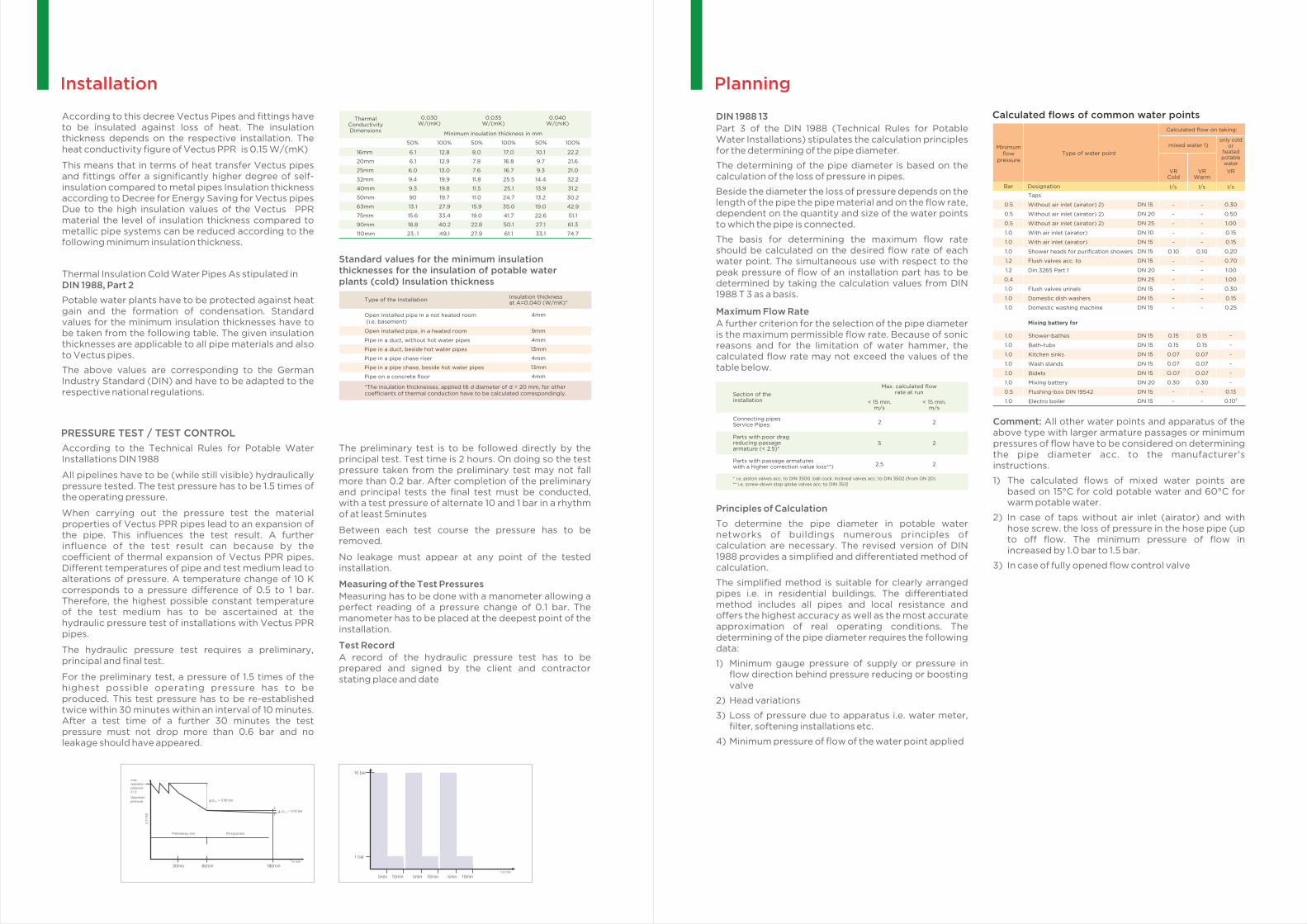
The linear expansion, described above, can be taken from the following tables and diagrams
Linear expansion DL in (mm): Vectus pipe a = 0.150 mm/mK
Installation Principles
Vectus Pipe50m
45m
40m
35m
30m
25m
20m
15m
10m
5m
Difference in temperature DT (k)
0K 10K 20K 30K 40K 50K 60K 70K 80K
600mm
500mm
400mm
300mm
200mm
100mm
0mm
Concealed Installation
Concealed installations generally do not require a consideration of the expansion pipes. The insulation according to DIN 1988 or the EnEV (Energieeinspar Verordnung) gives enough expansion space for the pipe.
In the case where the expansion is greater than the room to move in the insulation, the material absorbs any stress arising from a residual expansion.
The same applies to pipes, which do not have to be insulated according to current regulations.
A temperature induced linear expansion is prevented by the embedding in the floor, concrete or plaster. The compressive strain and tensile stress arising from this are not critical as they are absorbed by the material itself.

Bending Side
In most cases direction changes can be used to compensate for linear expansion in pipes. The length of a bending side L is calculated acc. to the following formula in BS
consideration of the calculated linear expansion and pipe dimension.
The values of the bending side can be taken directly from the tables and diagrams
Symbol Meanings: L - Length of the bending side (mm) K - Material specify constant - 15.0BS
d - Outside diameter (mm) D- Linear expansion (mm)L - Pipe Length (m) F - Fixed pointP
S - Sliding pointP
The bending side length is calculated according to the formula:
Expansion Loop
In most cases direction changes can be compensated through a change in direction, it becomes necessary to install an expansion loop with long and straight pipelines.
Consider the length of the bending side L as well as the breadth of the pipe bend A BS min
on constructing an expansion loop.
Symbol Meanings:
A - Width of expansion loop (mm)min
SD - Safety Distance - 150 mm
This pipe bend A is calculated according to the formula:min
The width of the expansion loop A should be at lease 210mm.min
Pre-stress
Where space is limited, it is possible to shorten the to tal width A as well as the length min
of the bending side I by its pre-stressing.BSV
Pre-stress installations, if planned and carried out carefully, offer an optically perfect installation, as the linear expansion is hardly visible.
The side length LSV is calculated according to the following calculation example:
Symbol Meanings:
L - Length of pre-stress (mm)BSV
The side length of expansion loops with pre-stresses calculated according to the following example:
Installation in Ducts
The installation of risers of Vectus pipe requires a branch pipe, which is elastic enough to take the linear expansion of the riser.
This can be ensured by a favourable fixing of the riser in the duct.
An adequate large pipe liner also gives sufficient elasticity to the branch-off pipe.
Furthermore the installation of a spring leg gives the appropriate elasticity.
Open Installation
In case of open installed pipes, as presentation is important there should be no deformation of the Pipe work. The coefficient of linear expansion of Vectus pipes: a Vectus = 0.150 mm/mK
Therefore, it is recommended to plan and install visible Vectus pipes, where linear expansion has to be considered. The following formula, calculation examples, data-tables and diagrams help to determine the linear expansion. Essential for the calculation of linear expansion is the difference between working temperature and maximum or minimum installation temperature.
Linear expansion due to temperature difference between operating temperature and installation.
Temperature can be compensated by different installation techniques
Installation
L = K x d x DBS
A = AI +SDmin
L = K x d x D/2BSV
Support Intervals
All pipe clamps in the ducts have to be installed as fixed points
Favourable fixing Large diameter pipe liner Installation of a spring leg
Pipe Diameter d (mm)
Vectus Pipe - SDR 6.0 & SDR 7.4
0
20
30
40
50
60
70
70
50
50
50
50
50
50
85
60
60
60
60
55
50
105
75
75
70
70
65
60
125
90
90
80
80
75
75
140
100
100
90
90
85
80
165
120
120
110
110
100
95
190
140
140
130
130
115
105
205
150
150
140
150
125
115
220
160
160
150
150
140
125
250
180
180
170
170
160
140
16 20 25 32 40 50 63 75 90 110
Support Intervals in cms.
Differencein temp.
DT(K)
Table to determine support intervals in conjunction with temperature and outside diameter
Vectus Pipe - SDR 11Table to determine support intervals for
Ocold water application (temperature of medium: 20 C) in conjunction with outside diameter.
Pipe Diameter d (mm)
16 20 25 32 40 50 63 75 90 110
Support Intervals in cms.
160
60 75 90 100 120 140 150 160 180 200 225
Central heating pipes, installed in heated rooms or building parts between heated rooms of the one user, where heat output can be controlled by open stop valves do not require a minimum thickness of the insulation.
This even applies to warm water pipes up to an inner diameter of 22 mm in flats, which are neither in the circulation nor have an additional electric heating.
Applying material with thermal conductivities different to 0.035W/mK the minimum thickness of the insulation has to be converted correspondingly.
For the conversion and the thermal conductivity of the insulation the ways and values of calculation described in the technical regulations must be applied.
The minimum insulation according to the table for heating distributions and heating pipes can be reduced as far as the same limit of heat output even for further insulation demands in consideration of the insulating effect of the pipe walls are guaranteed.
The decree for energy saving thermal protection and energy saving technique for buildings
Extract from § 12 addendum 5 of the EnEV
Thermal insulation of warm water pipes
Type of pipe/fitting
Inner diameter up to 22mm
Inner diameter more than 22 mm up to 35 mm
Inner diameter more than 35 mm up to 100 mm
Inner diameter more than 100 mm
Pipes and fittings, in wall- and ceiling openings, in crossing area of pipes, at pipe connections, at distributors
Pipes of central heating which have been installed after introduction of this decree between heated rooms of various users
Pipes in floor construction
Minimum thickness of insulation referred to thermal conductivity of 0.035W/(mK)
20mm
30mm
same as inner diameter
100mm
1/2 of the demandof line 1 to 4
1/2 of the demandof line 1 to 4
6mm
Line
1
2
3
4
5
6
7
Planning
DIN 1988 13
Part 3 of the DIN 1988 (Technical Rules for Potable Water Installations) stipulates the calculation principles for the determining of the pipe diameter.
The determining of the pipe diameter is based on the calculation of the loss of pressure in pipes.
Beside the diameter the loss of pressure depends on the length of the pipe the pipe material and on the flow rate, dependent on the quantity and size of the water points to which the pipe is connected.
The basis for determining the maximum flow rate should be calculated on the desired flow rate of each water point. The simultaneous use with respect to the peak pressure of flow of an installation part has to be determined by taking the calculation values from DIN 1988 T 3 as a basis.
Maximum Flow Rate
A further criterion for the selection of the pipe diameter is the maximum permissible flow rate. Because of sonic reasons and for the limitation of water hammer, the calculated flow rate may not exceed the values of the table below.
Principles of Calculation
To determine the pipe diameter in potable water networks of buildings numerous principles of calculation are necessary. The revised version of DIN 1988 provides a simplified and differentiated method of calculation.
The simplified method is suitable for clearly arranged pipes i.e. in residential buildings. The differentiated method includes all pipes and local resistance and offers the highest accuracy as well as the most accurate approximation of real operating conditions. The determining of the pipe diameter requires the following data:
1) Minimum gauge pressure of supply or pressure in flow direction behind pressure reducing or boosting valve
2) Head variations
3) Loss of pressure due to apparatus i.e. water meter, filter, softening installations etc.
4) Minimum pressure of flow of the water point applied
Connecting pipes Service Pipes:
Parts with poor dragreducing passagearmature (< 2.5)*
Parts with passage armatures with a higher correction value loss**)
Section of the installation
* i.e. piston valves acc. to DIN 3500. ball cock. Inclined valves acc. to DIN 3502 (from ON 20)
** i.e. screw-down stop globe valves acc. to DIN 3512
Max. calculated flowrate at run
< 15 min.m/s
< 15 min.m/s
2
5
2.5
2
2
2
Calculated flows of common water points
Minimum flow
pressureType of water point
Calculated flow on taking:
mixed water 1)only cold
or heated potable water
I/s I/s I/s
VR Cold
VR Warm
VR
DN 15
DN 20
DN 25
DN 10
DN 15
DN 15
DN 15
DN 20
DN 25
DN 15
DN 15
DN 15
-
-
-
-
-
0.10
-
-
-
-
-
-
-
-
-
-
-
0.10
-
-
-
-
-
-
0.30
0.50
1.00
0.15
0.15
0.20
0.70
1.00
1.00
0.30
0.15
0.25
0.5
0.5
0.5
1.0
1.0
1.0
1.2
1.2
0.4
1.0
1.0
1.0
DesignationBar
Taps
Without air inlet (airator) 2)
Without air inlet (airator) 2)
Without air inlet (airator) 2)
With air inlet (airator)
With air inlet (airator)
Shower heads for purification showers
Flush valves acc. to
Din 3265 Part 1
Flush valves urinals
Domestic dish washers
Domestic washing machine
Mixing battery for
DN 15
DN 15
DN 15
DN 15
DN 15
DN 20
DN 15
DN 15
0.15
0.15
0.07
0.07
O.07
0.30
-
-
Shower-bathes
Bath-tubs
Kitchen sinks
Wash stands
Bidets
Mixing battery
Flushing-box DIN 19542
Electro boiler
0.15
0.15
0.07
0.07
O.07
0.30
-
-
-
-
-
-
-
-
0.1330.10
1.0
1.0
1.0
1.0
1.0
1.0
0.5
1.0
Comment: All other water points and apparatus of the above type with larger armature passages or minimum pressures of flow have to be considered on determining the pipe diameter acc. to the manufacturer's instructions.
1) The calculated flows of mixed water points are based on 15°C for cold potable water and 60°C for warm potable water.
2) In case of taps without air inlet (airator) and with hose screw. the loss of pressure in the hose pipe (up to off flow. The minimum pressure of flow in increased by 1.0 bar to 1.5 bar.
3) In case of fully opened flow control valve
According to this decree Vectus Pipes and fittings have to be insulated against loss of heat. The insulation thickness depends on the respective installation. The heat conductivity figure of Vectus PPR is 0.15 W/(mK)
This means that in terms of heat transfer Vectus pipes and fittings offer a significantly higher degree of self-insulation compared to metal pipes Insulation thickness according to Decree for Energy Saving for Vectus pipes Due to the high insulation values of the Vectus PPR material the level of insulation thickness compared to metallic pipe systems can be reduced according to the following minimum insulation thickness.
Thermal Insulation Cold Water Pipes As stipulated in DIN 1988, Part 2
Potable water plants have to be protected against heat gain and the formation of condensation. Standard values for the minimum insulation thicknesses have to be taken from the following table. The given insulation thicknesses are applicable to all pipe materials and also to Vectus pipes.
The above values are corresponding to the German Industry Standard (DIN) and have to be adapted to the respective national regulations.
Standard values for the minimum insulation thicknesses for the insulation of potable water plants (cold) Insulation thickness
Open installed pipe in a not heated room (i.e. basement)
Open installed pipe, in a heated room
Pipe in a duct, without hot water pipes
Pipe in a duct, beside hot water pipes
Pipe in a pipe chase riser
Pipe in a pipe chase, beside hot water pipes
Pipe on a concrete floor
4mm
9mm
4mm
13mm
4mm
13mm
4mm
*The insulation thicknesses, applied t6 d diameter of d = 20 mm, for other coefficients of thermal conduction have to be calculated correspondingly.
Insulation thickness at A=0.040 (W/mK)*
Type of the Installation
30min 60min 180minin min
p in
ba
r
max.operationpressurex1.5
Operationpressure
Prelimanary test Principal test
p = 0.02 barmax
p = 0.06 barmax
10min 10min 10min5min 5min 5mint in min
1 bar
10 bar
ThermalConductivity Dimensions
Minimum insulation thickness in mm
16mm
20mm
25mm
32mm
40mm
50mm
63mm
75mm
90mm
110mm
0.030W/(mK)
0.035W/(mK)
0.040W/(mK)
50% 100%
6.1
6.1
6.0
9.4
9.3
90
13.1
15.6
18.8
23 .1
12.8
12.9
13.0
19.9
19.8
19.7
27.9
33.4
40.2
49.1
50% 100%
8.0
7.8
7.6
11.8
11.5
11.0
15.9
19.0
22.8
27.9
17,0
16.8
16.7
25.5
25.1
24.7
35.0
41.7
50.1
61.1
50% 100%
22.2
21.6
21.0
32.2
31.2
30.2
42.9
51.1
61.3
74.7
10.1
9.7
9.3
14.4
13.9
13.2
19.0
22.6
27.1
33.1
Installation
According to the Technical Rules for Potable Water Installations DIN 1988
All pipelines have to be (while still visible) hydraulically pressure tested. The test pressure has to be 1.5 times of the operating pressure.
When carrying out the pressure test the material properties of Vectus PPR pipes lead to an expansion of the pipe. This influences the test result. A further influence of the test result can because by the coefficient of thermal expansion of Vectus PPR pipes. Different temperatures of pipe and test medium lead to alterations of pressure. A temperature change of 10 K corresponds to a pressure difference of 0.5 to 1 bar. Therefore, the highest possible constant temperature of the test medium has to be ascertained at the hydraulic pressure test of installations with Vectus PPR pipes.
The hydraulic pressure test requires a preliminary, principal and final test.
For the preliminary test, a pressure of 1.5 times of the highest possible operating pressure has to be produced. This test pressure has to be re-established twice within 30 minutes within an interval of 10 minutes. After a test time of a further 30 minutes the test pressure must not drop more than 0.6 bar and no leakage should have appeared.
The preliminary test is to be followed directly by the principal test. Test time is 2 hours. On doing so the test pressure taken from the preliminary test may not fall more than 0.2 bar. After completion of the preliminary and principal tests the final test must be conducted, with a test pressure of alternate 10 and 1 bar in a rhythm of at least 5minutes
Between each test course the pressure has to be removed.
No leakage must appear at any point of the tested installation.
Measuring of the Test Pressures
Measuring has to be done with a manometer allowing a perfect reading of a pressure change of 0.1 bar. The manometer has to be placed at the deepest point of the installation.
Test Record
A record of the hydraulic pressure test has to be prepared and signed by the client and contractor stating place and date
PRESSURE TEST / TEST CONTROL
Installation
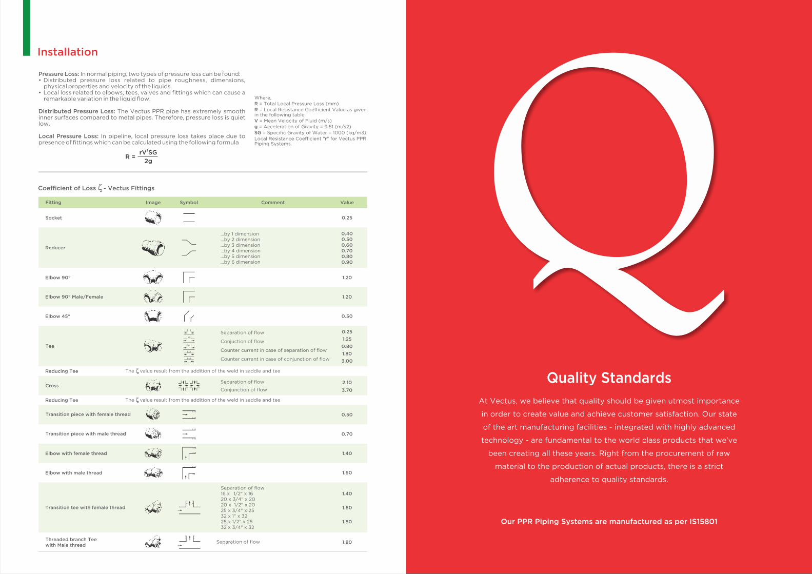
Coefficient of Loss - Vectus Fittings
Socket
Reducer
Elbow 90°
Elbow 90° Male/Female
Elbow 45°
Tee
Reducing Tee
Cross
Transition piece with female thread
Transition piece with male thread
Elbow with female thread
Elbow with male thread
Transition tee with female thread
Threaded branch Teewith Male thread
0.25
0.400.500.600.700.800.90
1.20
1.20
0.50
0.25
1.25
0.80
1.80
3.00
2.10
3.70
0.50
0.70
1.40
1.60
1.40
1.60
1.80
1.80
Reducing Tee
...by 1 dimension
...by 2 dimension
...by 3 dimension
...by 4 dimension
...by 5 dimension
...by 6 dimension
Separation of flow
Conjuction of flow
Counter current in case of separation of flow
Counter current in case of conjunction of flow
Separation of flow16 x �1/2" x 1620 x 3/4" x 2020 x 1/2" x 2025 x 3/4" x 2532 x 1" x 3225 x 1/2" x 2532 x 3/4" x 32
Separation of flow
Conjunction of flow
Separation of flow
The value result from the addition of the weld in saddle and tee
The value result from the addition of the weld in saddle and tee
Fitting Image Symbol Comment Value
Quality Standards
At Vectus, we believe that quality should be given utmost importance
in order to create value and achieve customer satisfaction. Our state
of the art manufacturing facilities - integrated with highly advanced
technology - are fundamental to the world class products that we've
been creating all these years. Right from the procurement of raw
material to the production of actual products, there is a strict
adherence to quality standards.
Our PPR Piping Systems are manufactured as per IS15801
Pressure Loss: In normal piping, two types of pressure loss can be found:• Distributed pressure loss related to pipe roughness, dimensions,
physical properties and velocity of the liquids.• Local loss related to elbows, tees, valves and fittings which can cause a
remarkable variation in the liquid flow.
Distributed Pressure Loss: The Vectus PPR pipe has extremely smooth inner surfaces compared to metal pipes. Therefore, pressure loss is quiet low.
Local Pressure Loss: In pipeline, local pressure loss takes place due to presence of fittings which can be calculated using the following formula
Where,R = Total Local Pressure Loss (mm)R = Local Resistance Coefficient Value as given in the following tableV = Mean Velocity of Fluid (m/s)
g = Acceleration of Gravity = 9.81 (m/s2)SG = Specific Gravity of Water = 1000 (kq/m3)Local Resistance Coefficient "r" for Vectus PPR Piping Systems.
R = 2rV SG
2g

16, 20, 25, 32, 40, 50, 63, 75, 90, 110, 160
SDR 6 • PN 20: Available in lengths of 1 & 3 meters
PPR Submersible Pipe
Available in lengths of 3 & 4 meters
16, 20, 25, 32, 40, 50
63, 75, 90, 110, 160
End Cap
20, 25, 32, 40, 50, 63
Tank Connection
16, 20, 25, 32, 40, 50
63, 75, 90, 110, 160
Coupler
16, 20, 25, 32, 40, 50
63, 75, 90, 110, 160
oElbow 90Long /Short Plug
20, 25
Thread Plug
20, 25
Cross Over
20, 25, 32, 40, 50, 63
Union
20, 40, 50, 63, 75
Flange Coupling
Equal Tee
16, 20, 25, 32, 40, 50
63, 75, 90, 110, 160
Pipe clip
20, 25, 32, 40, 50, 63
Ball Valve
16, 20, 25, 32, 40, 50
63, 75, 90, 110
16, 20, 25, 32, 40, 50, 63, 75, 90, 110, 160
SDR 7.4 • PN 16: Available in lengths of 1, 3, 4 & 6 meters
16, 20, 25, 32, 40, 50, 63, 75, 90, 110, 160
SDR 11 • PN 10: Available in lengths of 1 & 3 meters
32, 40, 50, 63, 75, 90, 110, 160
SDR 17.5 • PN 6: Available in lengths of 1, 3, 4 & 6 meters
Grades• Light• Economy• Medium• Heavy
Sizes: 32, 40, 50, 63, 75, 90, 110
PPR FittingsPPR Pipes
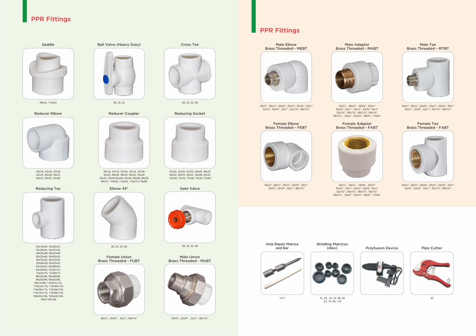
16x½”, 20x½”, 20x¾”, 25x½”
25x¾”, 25x1", 32x½”, 32x¾” 32x1"
32x1¼”, 40x1¼”, 40x1½”, 50x1¼”
50x1½”, 63x2", 75x2½”, 90x3", 110x4"
Male Adapter Brass Threaded - MABT
Female Adapter Brass Threaded - FABT
16x½”, 20x½”, 20x¾”, 25x½”
25x¾”, 25x1", 32x½”, 32x¾” 32x1"
32x1¼”, 40x1¼”, 40x1½”, 50x1¼”
50x1½”, 63x2", 75x2½”, 90x3", 110x4"
Male Elbow Brass Threaded - MEBT
16x½”, 20x½”, 20x¾”, 25x½”, 25x¾”, 25x1"
32x½”, 32x¾”, 32x1", 32x1¼”, 40x1¼”
Male Tee Brass Threaded - MTBT
16x½”, 20x½”, 20x¾”, 25x½”, 25x¾”, 25x1"
32x½”, 32x¾”, 32x1", 32x1¼”, 40x1¼”
Female Elbow Brass Threaded - FEBT
16x½”, 20x½”, 25x½”, 25x¾”, 25x1"
32x½”, 32x¾”, 32x1", 40x1¼”
Cross Tee
20, 25, 32, 40
Ball Valve (Heavy Duty)
20, 25, 32
Saddle
90x32, 110x32
Reducing Socket
25x20, 32x20, 32x25, 40x20, 40x25
40x32, 50x25, 50x32, 50x40, 63x32
63x50, 75x32, 75x40, 75x50, 75x63
Hole Repair Matrice and Bar
7x11
Welding Matrices (dies)
16, 20, 25, 32, 40, 50
63, 75, 90, 110
42
Pipe CutterPolyfusion Device
16x40, 50x75x 90x110
Reducer Coupler
20x16, 25x16, 25x20, 32x16, 32x20
32x25, 40x20, 40x25, 40x32, 50x20
50x32, 50x40 63x40, 63x50, 90x40, 90x50
90x75, 110x50, 110x63, 110x75,110x90
Reducing Tee
20x16x20, 25x20x25,
32x20x32, 32x25x32,
40x20x40, 40x25x40
40x32x40, 50x20x50,
50x25x50, 50x32x50,
50x40x50, 63x25x63
63x32x63, 63x40x63,
63x50x63, 75x25x75,
75x32x75, 75x40x75
90x32x90, 90x40x90,
90x50x90, 90x63x90,
90x75x90, 110x25x110,
110x32x110, 110x40x110
110x50x110, 110x63x110,
110x75x110, 110x90x110,
160x50x160, 160x63x160,
160x110x160
Reducer Elbow
20x16, 25x20, 32x20
32x25, 40x20, 40x25
40x32, 50x32, 50x40
20x½”, 25x¾” , 32x1", 40x1¼”
Female Union Brass Threaded - FUBT
20x½”, 25x¾” , 32x1", 40x1¼”
Male Union Brass Threaded - MUBT
Gate Valve
20, 25, 32, 40
Elbow 45°
20, 25, 32, 40
PPR Fittings
PPR Fittings
Female Tee Brass Threaded - FABT
16x½”, 20x½”, 20x¾”, 25x½”, 25x¾”, 25x1"
32x½”, 32x¾”, 32x1", 32x1¼”, 40x1¼”
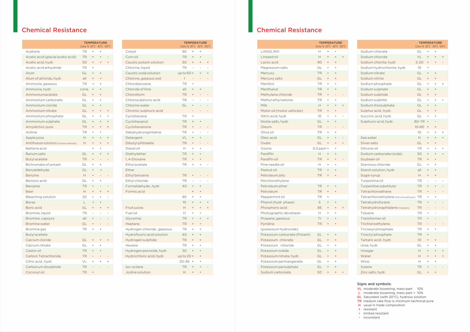
Chemical Resistance Chemical Resistance
TEMPERATUREConc % O20 C O60 C O100 C
TEMPERATUREConc % O20 C O60 C O100 C
TEMPERATUREConc % O20 C O60 C O100 C
TEMPERATUREConc % O20 C O60 C O100 C
Acetone TR + +
Acetic acid (glacial acetic acid) TR + • -
Acetic acid, hydr. 50 + + •
Acetic acid anhydride TR +
Alum GL + +
Alum of all kinds, hydr. all + +
Ammonia, gaseous TR + +
Ammonia, hydr. cone. + +
Ammoniumacetate GL + +
Ammonium carbonate GL + +
Ammonium cloride GL + +
Ammonium nitrate GL + + +
Ammonium phosphate GL + + +
Ammonium sulphate GL + + +
Amylalchol, pure TR + + +
Aniline TR • •
Apple juice H + + +
Antifreeze solution (motor vehicles) H + + +
Batterie acid + +
Barium salts GL + + +
Butyl acetete TR • - -
Bichromate of potash GL + +
Benzaldehyde GL + +
Benzine H • - -
Benzoic acid GL + +
Benzene TR • - -
Beer H + + +
Bleaching solution 20 • • -
Borax L + +
Boric acid GL + + +
Bromine, liquid TR - - -
Bromine, vapours all • - -
Bromine water GL • - -
Bromine gas TR + +
Butyl acetete
Calcium cloride GL + + +
Calcium nitrate GL + +
Castor oil TR + +
Carbon Tetrachloride TR - - -
Citric acid , hydr. VL + + +
Carbonum disulphide TR - - -
Coconut oil TR +
Cresol 90 + +
Corn oil TR + •
Caustic potash solution 50 + + +
Chlorine, liquid TR - - -
Caustic soda solution up to 60 + + +
Chlorine, gaseous wet 1 - - -
Chlorobenzene TR •
Chloride of lime all + +
Chloroform TR • - -
Chlorosulphonic acid TR - - -
Chlorine water GL • - -
Chromic sulphuric acid - - -
Cyclohexane TR +
Cyclohexanol TR + •
Cyclohexanone TR • - -
Dekahydronaphtaline TR • - -
Detergent VL + +
Dibutyl phthalate TR • - -
Diesel oil H + •
Diethylether TR + •
1, 4-Dioxane TR • •
Ethyl acetate TR + • -
Ether
Ethyl benzene TR • - -
Ethyl chloride TR - - -
Formaldehyde , hydr. 40 + +
Formic acid + •
85 + •
10 + + •
Fruit juices H + + +
Fuel oil H + •
Glycerine TR + + +
Heptane TR + •
Hydrogen chloride , gaseous TR + +
Hydrofluoric acid solution 40 + +
Hydrogen sulphide TR + +
Hexane TR + •
Hydrogen peroxide, hydr. 30 + •
Hydrochloric acid, hydr. up to 20 + +
20-36 + •
Iso-octane TR + • -
Jodine solution H + •
LANOLIN® H + •
Linseed oil H + + +
Lactic acid 90 + +
Magnesium salts GL + +
Mercury TR + +
Mercury salts GL + +
Menthol TR + •
Menthanol TR + +
Methylene chloride TR • - -
Methyl ethyl ketone TR + •
Milk H + + +
Motor oil (motor vehicles) TR + •
Nitric acid, hydr. 10 + • -
Nickle salts, hydr. GL + +
Oleum TR - - -
Olive oil TR + +
Oleic acid GL + • -
Oxalic GL + + •
Ozone 0,5 ppm + •
Paraffin H + +
Paraffin oil TR + • -
Pine needle oil H + •
Peanut oil TR + +
Petroleum jelly TR + •
Perchlorethylene
Petroleum ether TR + •
Petroleum TR + •
Peppermint oil TR +
Phenol (hydr. phase) 5 + +
Phosphoric acid 85 + + +
Photographic developer H + +
Propane, gaseous Tr + •
Pyridine TR • •
(potassium hydroxide)
Potassium carbonate (Potash) GL + +
Potassium chlorate GL + +
Potassium chloride GL + +
Potassium iodide GL + +
Potassium nitrate, hydr. GL + +
Potassium permanganate GL + +
Potassium persulphate GL + +
Sodium carbonate 50 + + •
Sodium chlorate GL + +
Sodium chloride VL + + +
Sodium chlorite, hydr. 2-20 + • -
Sodium hydrochlorite, hydr. 10 +
Sodium nitrate GL + +
Sodium nitrite GL + +
Sodium phosphate GL + + +
Sodium sulphate GL + +
Sodium sulphide GL + +
Sodium sulphite GL + + +
Sodium thiosulphate GL + +
Sulphur acid , hydr. GL + +
Succinic acid, hydr. GL + +
Sulphuric acid, hydr. 80-TR • -
10-80 + +
10 + + +
Sea water H + + +
Silver salts GL + +
Silicone oil TR + + +
Sodium carbonate (soda) 50 + + •
Soybean oil TR + •
Stannous chloride GL + +
Starch solution, hydr. all + +
Sugar syrup H + +
Turpentine oil TR - - -
Turpentine substitute TR + • -
Tetrachloroethane TR • - -
Tetrachloroethylene (Perchlorethylen) TR • •
Tetrahydrofurane TR • - -
Tetrahydronaphtalene (Tetralin) TR - - -
Toluene TR • -
Transformer oil TR • -
Trichloroethylene TR - - -
Tricresyl phosphate TR + •
Trioctyl phosphate TR +
Tartaric acid , hydr. 10 + +
Urea, hydr. GL + +
Vinegar H + + +
Water H + + +
Wine H + +
Xylene TR • - -
Zinc salts, hydr. GL + +
Signs and symbols:
VL
L
GL
TR
H
+
•
-
moderate loosening, mass-part 10%
moderate loosening, mass-part > 10%
Saturated (with 20°C), hydrous solution
medium rate flow is minimum-technical pure
usual in trade composition
resistant
limited resistant
inconstant

VECTUS INDUSTRIES LIMITEDA-36, Sector 83, Noida 201305, UP • Tel.: 0120-4753200
E-mail: [email protected] • www.vectus.in • Toll Free: 1800 120 12345
VECTUS GROUP BRANDS
Download the VECTUS app from
QR Code
CIN No: U25202MP2007PLC019781
Corporate Office
Factory
Depot
Regional Sales Office
Tumkur
Trichy
Kashipur
Banmore
Kanpur
Bhopal
Indore
Raipur
Noida
Haridwar
Kolkata
Sikandarabad
Bangalore
Jaipur
Ahmedabad
Dahej
UnaJalandhar
Jammu
Pan India
Sales & Support
Network


