21
PRESENTATION ON RAILWAY COACHES INDIAN RAILWAY " Lifeline Of The Nation " BY- SHASHIKANT CHOUDHAR 10ERIME053
| Date post: | 11-Sep-2014 |
| Category: |
Education |
| View: | 7,815 times |
| Download: | 269 times |
PRESENTATION ON RAILWAY COACHES
INDIAN RAILWAY " Lifeline Of The Nation "
BY- SHASHIKANT CHOUDHARY 10ERIME053

-: CONTENT :-
INTRODUCTION
MAINTENANCE SCHEDULES
WHEEL PROFILE & DEFECTS
TYPE OF COACH
AXLE , BRAKE DISC & BRAKE SHOES
AIR BRAKE SYSTEM
BOGIE FRAME
BODY SHELL & WINDOW UNIT
WATER TANKS
CDTS

-: INDIAN RAILWAY :-
First passenger train introduced in India on 16 April 1853 between Mumbai to Thane (34 km).
Over 10,000 trains daily, transporting over 8,900 million passengers and over 1050 million tones of freight per year.
Indian Railways is the world's ninth largest organisation, by number of employees, with over 1.4 million employees.
As of 31 March 2013, 23,541 km (36%) of the total 65,000 km route length was electrified.
The number of zones in Indian Railways increased from six to eight in 1951, nine in 1952 and sixteen in 2003. Presently there are 17 zones & 84 divisions.
www.indianrailways.gov.in
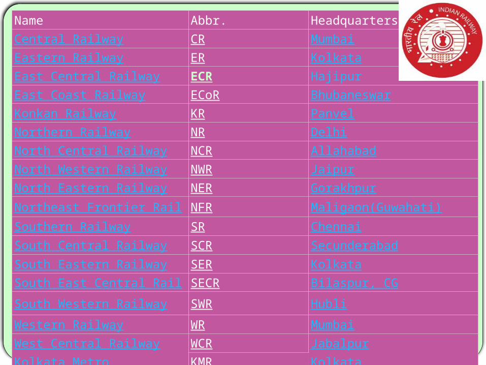
Name Abbr. HeadquartersCentral Railway CR MumbaiEastern Railway ER KolkataEast Central Railway ECR HajipurEast Coast Railway ECoR BhubaneswarKonkan Railway KR PanvelNorthern Railway NR Delhi
North Central Railway NCR AllahabadNorth Western Railway NWR JaipurNorth Eastern Railway NER Gorakhpur
Northeast Frontier Railway NFR Maligaon(Guwahati)
Southern Railway SR Chennai
South Central Railway SCR Secunderabad
South Eastern Railway SER KolkataSouth East Central Railway SECR Bilaspur, CG
South Western Railway SWR Hubli
Western Railway WR Mumbai
West Central Railway WCR Jabalpur
Kolkata Metro KMR Kolkata

-: Coach Repair Workshop, Harnaut :-
Foundation stone was laid by A.P.J. Abdul Kalam on June 30, 2003 Site location - Harnaut, Distt- Nalanda (Bihar) ,under ECR
Total Land - 113 Acres (workshop 76 , staff quarters 37)
Year of sanction - 2003-04
Sanctioned Cost - Rs. 224 Cores.
Revised sanctioned Cost - Rs. 337 Cores.
Expenditure - Rs 252.03 Cores. (up to 31.03.13 )
Plant Capacity - POH of 50 coaches per month
Sanctioned staff - 1158
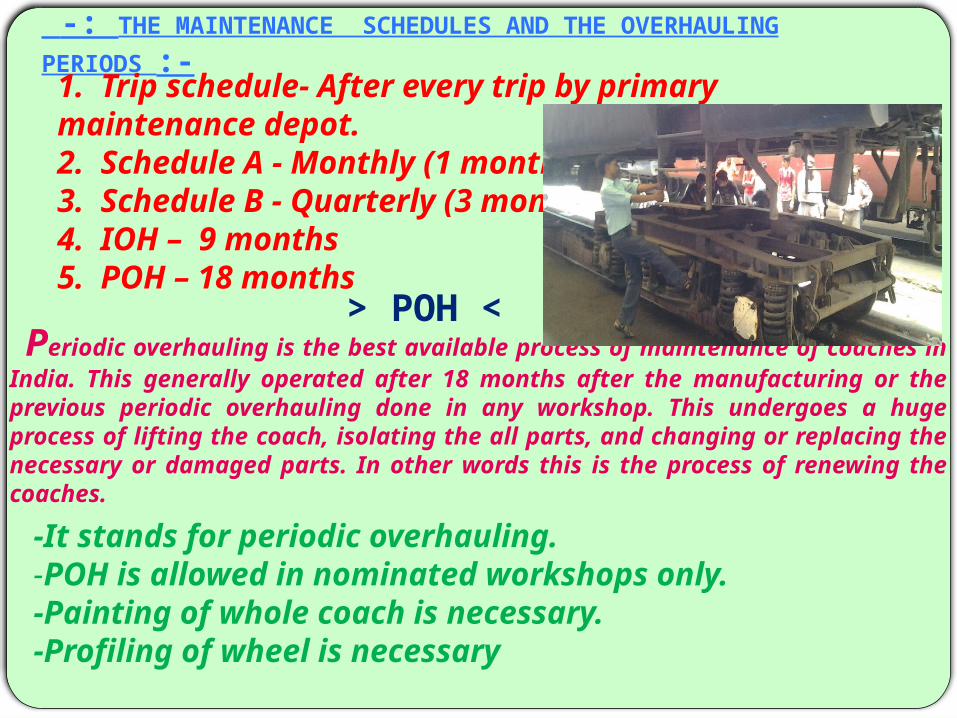
-: THE MAINTENANCE SCHEDULES AND THE OVERHAULING PERIODS :-
1. Trip schedule- After every trip by primary maintenance depot. 2. Schedule A - Monthly (1 month ) 3. Schedule B - Quarterly (3 months ) 4. IOH – 9 months5. POH – 18 months
Periodic overhauling is the best available process of maintenance of coaches in India. This generally operated after 18 months after the manufacturing or the previous periodic overhauling done in any workshop. This undergoes a huge process of lifting the coach, isolating the all parts, and changing or replacing the necessary or damaged parts. In other words this is the process of renewing the coaches.
> POH <
-It stands for periodic overhauling. -POH is allowed in nominated workshops only.-Painting of whole coach is necessary. -Profiling of wheel is necessary
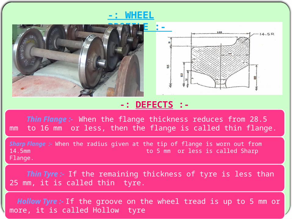
-: WHEEL PROFILE :-
-: DEFECTS :-
Thin Flange :- When the flange thickness reduces from 28.5 mm to 16 mm or less, then the flange is called thin flange.
Sharp Flange :- When the radius given at the tip of flange is worn out from 14.5mm to 5 mm or less is called Sharp Flange.
Thin Tyre :- If the remaining thickness of tyre is less than 25 mm, it is called thin tyre.
Hollow Tyre :- If the groove on the wheel tread is up to 5 mm or more, it is called Hollow tyre

THIN TYRE HOLLOW TYRE
THIN FLANGE SHARP FLANGE
Tyre defect gauge

COACH
I.C.F. L.H.B.140 km/hIntegral coach factory
Linke Holfmann Busch 160 km/h
DIMENSIONS OF COACH SHELL ICF LHB Length With Buffer 22296 mm 24000 mm Length Without Buffer 21336 mm 23540 mmWidth 3245 mm 3030 mm Life 25 Years 30 Years
Noise level 60 decibelsNoise level 100 decibels

-: AXLE :-
It is the main long cylindrical bar on which bogie are fixed with the help of bearings. This is made of steel as above. Each axle contains 2 wheels, the brake cylinders are also attached to it and in case of LHB coaches, the braking discs are fixed on to the axle.
The axle mounted brake disc consists of a gray cast iron friction ring and a cast steel hub, connected by means of radially arranged elastic resilient sleeves which are secured in the hub by means of hexagon screws. The friction ring is manufactured as a solid component or in a split version. In the latter case, the two halves are held together by two tight –fit screws. DISC
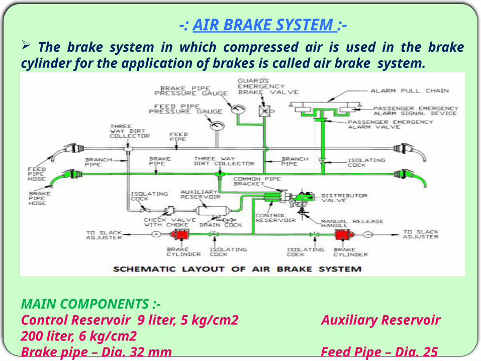
-: AIR BRAKE SYSTEM :- The brake system in which compressed air is used in the
brake cylinder for the application of brakes is called air brake system.
MAIN COMPONENTS :-Control Reservoir 9 liter, 5 kg/cm2 Auxiliary Reservoir 200 liter, 6 kg/cm2Brake pipe – Dia. 32 mm Feed Pipe – Dia. 25 mm

Under normal conditions the Brake pipe is charged with 5kg/cm2 from the loco. The control reservoir and the Auxiliary reservoir are charged with 5 kg/cm2 and 6 kg/cm2 respectively from BP through Distributor valve.
When the brake pipe is charged at 5 kg/cm2 the brake cylinder is connected to exhaust through distributor valve in order to keep the brake in released position fully.
Whenever the brake pipe pressure is reduced below the CR pressure, the DV connects the auxiliary reservoir with the brake cylinder and the air from AR is sent into the brake cylinder to apply the brake.
Whenever the brake pipe pressure is equal to CR pressure the DV disconnects the BC from AR and in turn connects the BC with Exhaust for the release of brakes fully.
-: Working Principle :-
The different processes involved in working :- a) Charging b) Application c) Release
-: BRAKE SHOE :-
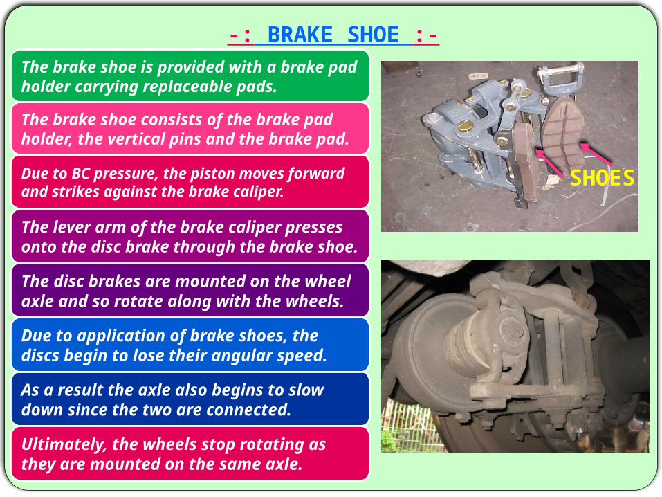
The brake shoe is provided with a brake pad holder carrying replaceable pads.
The brake shoe consists of the brake pad holder, the vertical pins and the brake pad.
SHOESDue to BC pressure, the piston moves forward and strikes against the brake caliper.
The lever arm of the brake caliper presses onto the disc brake through the brake shoe.
The disc brakes are mounted on the wheel axle and so rotate along with the wheels.
Due to application of brake shoes, the discs begin to lose their angular speed.
As a result the axle also begins to slow down since the two are connected.
Ultimately, the wheels stop rotating as they are mounted on the same axle.
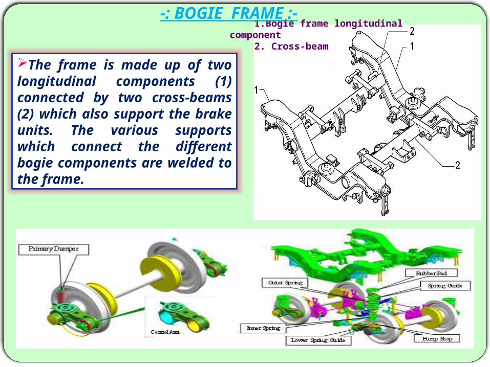
1.Bogie frame longitudinal component 2. Cross-beam
-: BOGIE FRAME :-
The frame is made up of two longitudinal components (1) connected by two cross-beams (2) which also support the brake units. The various supports which connect the different bogie components are welded to the frame.
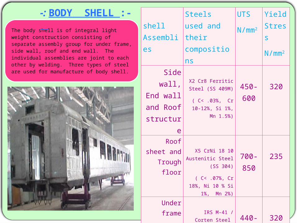
Sshell Assemblies
Steels used and their compositions
UTS
N/mm2
Yield Stress
N/mm2
Side wall, End wall and Roof structure
X2 Cr8 Ferritic Steel (SS 409M)
( C< .03%, Cr 10-12%, Si 1%, Mn
1.5%)
450-600
320
Roof sheet and Trough
floorX5 CrNi 18 10
Austenitic Steel (SS 304)
( C< .07%, Cr 18%, Ni 10 % Si 1%, Mn
2%)
700-850
235
Under frame IRS M-41 / Corten
Steel
( C < .01%, Cr .35 -.6%, Ni .2 - .4%
Cu .3 - .6% Si .3 - .7%, Mn .25%)
440-480
320
The body shell is of integral light weight construction consisting of separate assembly group for under frame, side wall, roof and end wall. The individual assemblies are joint to each other by welding. Three types of steel are used for manufacture of body shell.
-: BODY SHELL :-

-: WINDOW UNITS :- The sealed window units consist of 8.4 mm outer glass and 4 mm inner glass with 6 mm Argon gas filled. Argon is an inexpensive, non-toxic, odorless gas .
It increase sound proofing characteristics of the window.
Minimizes heat exchange through the window.
Argon will not corrode the window material.
This type of windows can even block ultraviolet rays.
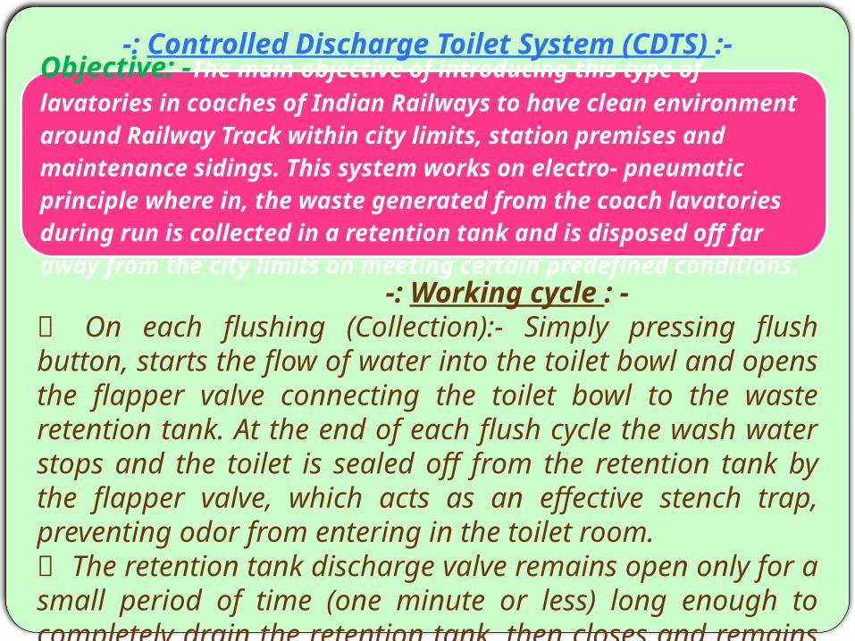
-: Controlled Discharge Toilet System (CDTS) :- Objective: -The main objective of introducing this type of lavatories in coaches of Indian Railways to have clean environment around Railway Track within city limits, station premises and maintenance sidings. This system works on electro- pneumatic principle where in, the waste generated from the coach lavatories during run is collected in a retention tank and is disposed off far away from the city limits on meeting certain predefined conditions. -: Working cycle : - On each flushing (Collection):- Simply pressing flush button, starts the flow of water into the toilet bowl and opens the flapper valve connecting the toilet bowl to the waste retention tank. At the end of each flush cycle the wash water stops and the toilet is sealed off from the retention tank by the flapper valve, which acts as an effective stench trap, preventing odor from entering in the toilet room. The retention tank discharge valve remains open only for a small period of time (one minute or less) long enough to completely drain the retention tank, then closes and remains closed until the required parameters are again satisfied.

The waste is stored in the retention tank until the following two parameter are satisfied.1) The train should be in acceleration & running above 30kmph and the number of flushing should be More than five.
2) Train should be in retardation and reducing speed of 30kmph irrespective number of flushes.
Water consumption is only 2.5 liters per flush cycle for the Indian style toilet Bowl and 1.5 liters for the European style toilet Bowl.
Programmable Logic Controller (PLC):- It is the heart of the system. It senses the speed of the coach and no of flushes and gets all the operations done by actuating corresponding valves. .

-:WATER TANKS :-3 types of water tanks are provided in LHB
coach685 liters: -2 stainless steel water tanks of 685 liters capacity each. These tanks are installed in under frame are fixed with frames and are secured by safety belts. These tanks constitute the fresh water reserves in the passenger coaches. Water level indicator has been provided in these tanks.
450 liters: -One stainless steel water tanks of 450 liters capacity. These tanks are installed in under frame, fixed with frames and is secured by safety belts. This tank installed in the under frame constitute the fresh water reserves for the generator car.
30 liters:- 3-stainless steel water tanks of 30 liters capacity installed one in each lavatory in the roof and are continuously fresh-water-fed by means of pumps. These tanks are installed alone and are fixed with 2 supports which are equipped with belts.
Thank You For your time
ANY QUERY….


![01] PT cover March 2014 - MTLEXS.COM · 2014-05-28 · The facility will manufacture Linke Hofmann Busch (LHB) design stainless steel coaches. Union Railway Minister, Mallikarjun](https://static.documents.pub/doc/80x56/5f70082b7df3ff70cb6ead65/01-pt-cover-march-2014-2014-05-28-the-facility-will-manufacture-linke-hofmann.jpg)


