392
1 © 2003 Cisco Systems, Inc. All rights reserved. APRICOT 2004 Practical Deployment Guidelines for MPLS-VPN Networks Azhar Sayeed and Monique Morrow [email protected] , [email protected]
1© 2003 Cisco Systems, Inc. All rights reserved.APRICOT 2004
Practical Deployment Guidelines for MPLS-VPN Networks
Azhar Sayeed and Monique Morrow

222© 2003 Cisco Systems, Inc. All rights reserved.APRICOT 2004
Prerequisites
• Must understand fundamental MPLS principles
• Must understand basic routing especially BGP

3© 2003 Cisco Systems, Inc. All rights reserved.APRICOT 2004
Introduction to MPLS
Azhar Sayeed

444© 2003 Cisco Systems, Inc. All rights reserved.APRICOT 2004
Agenda
• Background • Technology Basics
What is MPLS? Where Is it Used?
• Label Distribution in MPLS NetworksLDP, RSVP, BGP
• Building MPLS Based ServicesVPNsAToMTraffic Engineering
• ConfigurationsConfiguring MPLS, LDP, TE
• Summary

5© 2003 Cisco Systems, Inc. All rights reserved.APRICOT 2004
Background
5© 1999, Cisco Systems, Inc.
666© 2003 Cisco Systems, Inc. All rights reserved.APRICOT 2004
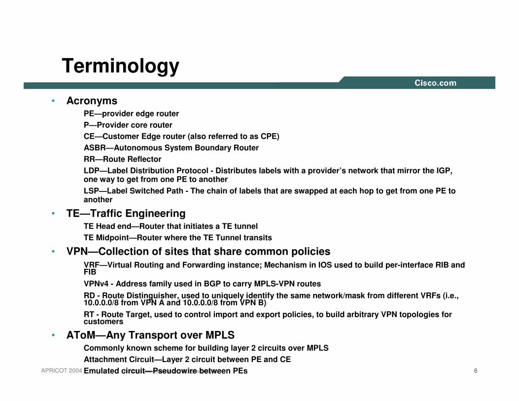
Terminology
• AcronymsPE—provider edge routerP—Provider core routerCE—Customer Edge router (also referred to as CPE)ASBR—Autonomous System Boundary RouterRR—Route ReflectorLDP—Label Distribution Protocol - Distributes labels with a provider’s network that mirror the IGP, one way to get from one PE to anotherLSP—Label Switched Path - The chain of labels that are swapped at each hop to get from one PE to another
• TE—Traffic EngineeringTE Head end—Router that initiates a TE tunnelTE Midpoint—Router where the TE Tunnel transits
• VPN—Collection of sites that share common policiesVRF—Virtual Routing and Forwarding instance; Mechanism in IOS used to build per-interface RIB and FIBVPNv4 - Address family used in BGP to carry MPLS-VPN routesRD - Route Distinguisher, used to uniquely identify the same network/mask from different VRFs (i.e., 10.0.0.0/8 from VPN A and 10.0.0.0/8 from VPN B)RT - Route Target, used to control import and export policies, to build arbitrary VPN topologies for customers
• AToM—Any Transport over MPLSCommonly known scheme for building layer 2 circuits over MPLSAttachment Circuit—Layer 2 circuit between PE and CEEmulated circuit—Pseudowire between PEs

777© 2003 Cisco Systems, Inc. All rights reserved.APRICOT 2004
Evolution of MPLS
• From Tag Switching
• Proposed in IETF—Later combined with other proposals from IBM (ARIS), Toshiba (CSR)
1996 1997 1998 1999 2000 2001Time
Cisco Calls aBOF at IETF to
StandardizeTag Switching
Cisco Calls aBOF at IETF to
StandardizeTag Switching
Traffic Engineering Deployed
Traffic Engineering Deployed
MPLS VPNDeployed
MPLS VPNDeployed
Large Scale DeploymentLarge Scale Deployment
Cisco Ships MPLS (Tag Switching)
Cisco Ships MPLS (Tag Switching)
Cisco ShipsMPLS TE
Cisco ShipsMPLS TE
MPLS Group Formally Chartered
by IETF
MPLS Group Formally Chartered
by IETF
888© 2003 Cisco Systems, Inc. All rights reserved.APRICOT 2004
What Is MPLS?
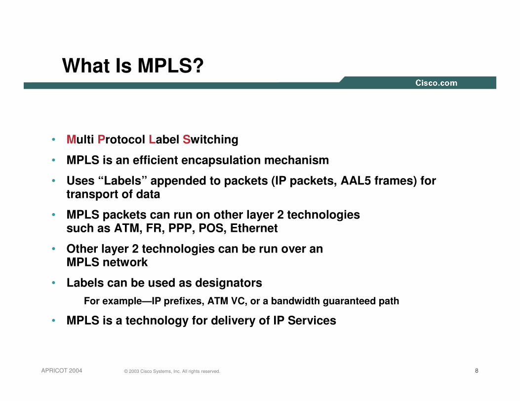
• Multi Protocol Label Switching
• MPLS is an efficient encapsulation mechanism
• Uses “Labels” appended to packets (IP packets, AAL5 frames) for transport of data
• MPLS packets can run on other layer 2 technologies such as ATM, FR, PPP, POS, Ethernet
• Other layer 2 technologies can be run over an MPLS network
• Labels can be used as designatorsFor example—IP prefixes, ATM VC, or a bandwidth guaranteed path
• MPLS is a technology for delivery of IP Services

999© 2003 Cisco Systems, Inc. All rights reserved.APRICOT 2004
Original Motivation of MPLS
• Allow Core routers/networking devices to switch packets based some simplified header
• Provide a highly scalable mechanism that was topology driven rather than flow driven
• Leverage hardware so that simple forwarding paradigm can be used
• It has evolved a long way from the original goalHardware became better and looking up longest best match was no longer an issue
By associating Labels with prefixes, groups of sites or bandwidth paths or light paths new services such as MPLS VPNs and Traffic engineering, GMPLS were now possible

101010© 2003 Cisco Systems, Inc. All rights reserved.APRICOT 2004
Overlay vs. Peer Networks
• Overlay network: customer’s IP network is overlaid on top of the provider’s network
Provider’s IP transport (FR, ATM, etc.) creates private IP network for customer
Most technologies that carry IP are p2p
Large p2p networks are hard to maintain
N^2 provisioning vs. inefficient routing
Even with hub and spoke, need lots of stuff at the hub

111111© 2003 Cisco Systems, Inc. All rights reserved.APRICOT 2004
Overlay Network
• Provider sells a circuit service
• Customers purchases circuits to connect sites, runs IP
• N sites, (N*(N-1))/2 circuits for full mesh—expensive
• The big scalability issue here is routing peers—N sites, each site has N-1 peers
• Hub and spoke is popular, suffers from the same N-1 number of routing peers
• Hub and spoke with static routes is simpler, still buying N-1 circuits from hub to spokes
• Spokes distant from hubs could mean lots of long-haul circuits
Provider(FR, ATM, etc.)

121212© 2003 Cisco Systems, Inc. All rights reserved.APRICOT 2004
Peer Network
• Provider and customer exchange IP routing information directly
Customer only has one routing peer per site
• Need to separate customer’s IP network from provider’s network
Customer A and Customer B need to not talk to each other
Customer A and Customer B may have the same address space (10.0.0.0/8, 161.44.0.0/16, etc.)
• VPN is provisioned and run by the provider
• MPLS-VPN does this without p2p connections

131313© 2003 Cisco Systems, Inc. All rights reserved.APRICOT 2004
Peer Network
• Provider sells an MPLS-VPN service
• Customers purchases circuits to connect sites, runs IP
• N sites, N circuits into provider
• Access circuits can be any media at any point (FE, POS, ATM, T1, dial, etc.)
• Full mesh connectivity without full mesh of L2 circuits
• Hub and spoke is also easy to build
• Spokes distant from hubs connect to their local provider’s POP, lower access charge because of provider’s size
• The Internet is a large peer network
Provider(MPLS-VPN)
141414© 2003 Cisco Systems, Inc. All rights reserved.APRICOT 2004
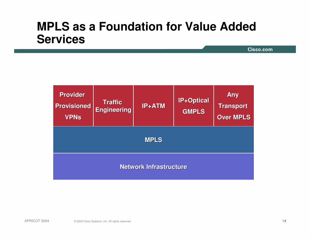
IP+ATMIP+ATMIP+OpticalIP+Optical
GMPLSGMPLS
MPLS as a Foundation for Value Added Services
Provider Provider
ProvisionedProvisioned
VPNsVPNs
MPLSMPLS
Traffic Traffic EngineeringEngineering
Network InfrastructureNetwork Infrastructure
Any Any
Transport Transport
Over MPLSOver MPLS

15© 2003 Cisco Systems, Inc. All rights reserved.APRICOT 2004
Technology Basics
Azhar Sayeed

161616© 2003 Cisco Systems, Inc. All rights reserved.APRICOT 2004
Label Header for Packet Media
• Can be used over Ethernet, 802.3, or PPP links
• Uses two new Ethertypes/PPP PIDs
• Contains everything needed at forwarding time
• One word per label
Label = 20 bitsCOS/EXP = Class of Service, 3 bitsS = Bottom of Stack, 1 bitTTL = Time to Live, 8 bits
0 1 2 30 1 2 3 4 5 6 7 8 9 0 1 2 3 4 5 6 7 8 9 0 1 2 3 4 5 6 7 8 9 0 1
Label EXP S TTL

171717© 2003 Cisco Systems, Inc. All rights reserved.APRICOT 2004
Encapsulations
LabelPPP HeaderPPP Header Layer 2/L3 PacketLayer 2/L3 PacketPPP Header(Packet over SONET/SDH)
ATM MPLS Cell Header HECHEC
Label
DATADATACLPCLPPTIPTIVCIVCIGFCGFC VPIVPI
Label MAC HeaderMAC Header Layer 2/L3 PacketLayer 2/L3 PacketLAN MAC Label Header
One or More Labels Appended to the Packet

181818© 2003 Cisco Systems, Inc. All rights reserved.APRICOT 2004
Forwarding Equivalence Class
• Determines how packets are mapped to LSP
IP Prefix/host address
Layer 2 Circuits (ATM, FR, PPP, HDLC, Ethernet)
Groups of addresses/sites—VPN x
A Bridge/switch instance—VSI
Tunnel interface—Traffic Engineering
191919© 2003 Cisco Systems, Inc. All rights reserved.APRICOT 2004
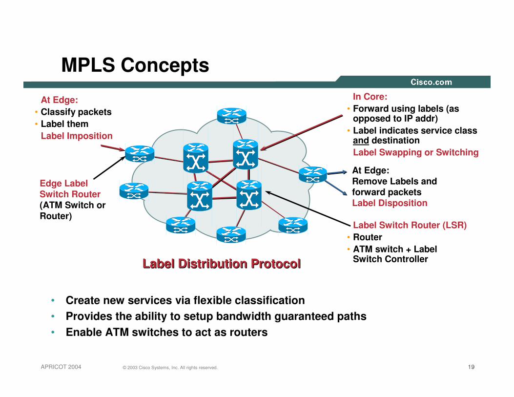
MPLS Concepts
• Create new services via flexible classification• Provides the ability to setup bandwidth guaranteed paths• Enable ATM switches to act as routers
At Edge:• Classify packets• Label them
Label Imposition
In Core:• Forward using labels (as
opposed to IP addr)• Label indicates service class
and destinationLabel Swapping or Switching
Label Switch Router (LSR)• Router• ATM switch + Label
Switch ControllerLabel Distribution ProtocolLabel Distribution Protocol
Edge Label Switch Router(ATM Switch or Router)
At Edge:Remove Labels and forward packetsLabel Disposition

202020© 2003 Cisco Systems, Inc. All rights reserved.APRICOT 2004
MPLS Operation
1a. Existing routing protocols (e.g. OSPF, IS-IS) establish reachability to destination networks1b. Label Distribution Protocol (LDP) establishes label to destination network mappings
2. Ingress Edge LSR receives packet, performs Layer 3 value-added services, and “labels” packets 3. LSR switches
packets using label swapping
4. Edge LSR at egress removes label and delivers packet
21© 2003 Cisco Systems, Inc. All rights reserved.APRICOT 2004
Label Distribution in MPLS Networks
Azhar Sayeed
222222© 2003 Cisco Systems, Inc. All rights reserved.APRICOT 2004
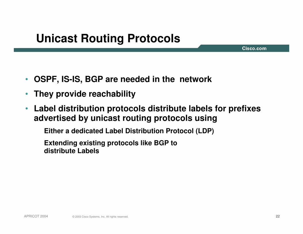
Unicast Routing Protocols
• OSPF, IS-IS, BGP are needed in the network
• They provide reachability
• Label distribution protocols distribute labels for prefixes advertised by unicast routing protocols using
Either a dedicated Label Distribution Protocol (LDP)
Extending existing protocols like BGP to distribute Labels

232323© 2003 Cisco Systems, Inc. All rights reserved.APRICOT 2004
Label Distribution Protocol
• Defined in RFC 3035 and 3036• Used to distribute Labels in a
MPLS network• Forwarding Equivalence Class
How packets are mapped to LSPs (Label Switched Paths)
• Advertise Labels per FEC Reach destination a.b.c.d with label x
• Discovery

242424© 2003 Cisco Systems, Inc. All rights reserved.APRICOT 2004
Router Example: Forwarding Packets
0
1
1
128.89
171.69
0
128.89.25.4 Data 128.89.25.4 Data
128.89.25.4 Data128.89.25.4 Data
Packets Forwarded Based on IP Address
...
128.89128.89
171.69
addressprefix I/F
1
1
...
128.89128.89
171.69
addressprefix I/F
0
1 ...
128.89128.89
addressprefix I/F
0
252525© 2003 Cisco Systems, Inc. All rights reserved.APRICOT 2004
MPLS Example: Routing Information
128.89
171.69
1
01
In label
Address Prefix
128.89
171.69
...
OutI’face
1
1
...
Out label
In label
Address Prefix
128.89
171.69
...
OutI’face
0
1
...
Out label
In label
Address Prefix
128.89
...
OutI’face
0
...
Out label
0
You can reach 171.69 thru meYou can reach 171.69 thru me
You can reach 128.89 and You can reach 128.89 and 171.69 thru me171.69 thru me
Routing Updates (OSPF, EIGRP, …)
You can reach 128.89 thru meYou can reach 128.89 thru me

262626© 2003 Cisco Systems, Inc. All rights reserved.APRICOT 2004
MPLS Example: Assigning Labels
128.89
171.69
1
01
In label
-
-
...
Address Prefix
128.89
171.69
...
OutI’face
1
1
...
Out label
4
5
...
In label
4
5
...
Address Prefix
128.89
171.69
...
OutI’face
0
1
...
Out label
9
7
...
In label
9
...
Address Prefix
128.89
...
OutI’face
0
...
Out label
-
...
0
Use label 7 for 171.69Use label 7 for 171.69
Use label 4 for 128.89 andUse label 4 for 128.89 andUse label 5 for 171.69Use label 5 for 171.69
Label Distribution Protocol (LDP)(Downstream Allocation)
Use label 9 for 128.89Use label 9 for 128.89

272727© 2003 Cisco Systems, Inc. All rights reserved.APRICOT 2004
MPLS Example: Forwarding Packets
128.89
171.69
1
0
1
In label
-
-
...
Address Prefix
128.89
171.69
...
OutI’face
1
1
...
Out label
4
5
...
In label
4
5
...
Address Prefix
128.89
171.69
...
OutI’face
0
1
...
Out label
9
7
...
128.89.25.4 Data4128.89.25.4 Data
128.89.25.4 Data
128.89.25.4 Data9
In label
9
...
Address Prefix
128.89
...
OutI’face
0
...
Out label
-
...
0
Label Switch Forwards Based on Label

282828© 2003 Cisco Systems, Inc. All rights reserved.APRICOT 2004
Label Distribution Modes
• Downstream unsolicitedDownstream node just advertises labels for prefixes/FEC reachable via that device
Previous example
• Downstream on-demandUpstream node requests a label for a learnt prefix via the downstream node
Next example—ATM MPLS

292929© 2003 Cisco Systems, Inc. All rights reserved.APRICOT 2004
In label
Address Prefix
128.89
171.69
...
OutI’face
1
1
...
Out label
In I/F
Address Prefix
128.89
171.69
...
OutI’face
0
1
...
Out label
In I/F
Address Prefix
128.89
...
OutI’face
0
...
Out label
In label
In label
2
1
ATM MPLS Example: Requesting Labels
128.89
171.69
1
010
I need a label for 128.89I need a label for 128.89
Label Distribution Protocol (LDP)(Downstream Allocation on Demand)
I need a label for 128.89I need a label for 128.89
I need a label for 171.69I need a label for 171.69
I need another label for 128.89I need another label for 128.89
I need a label for 128.89I need a label for 128.89
I need a label for 171.69I need a label for 171.693

303030© 2003 Cisco Systems, Inc. All rights reserved.APRICOT 2004
3
In label
Address Prefix
128.89
171.69
...
OutI’face
1
1
...
Out label
In I/F
Address Prefix
128.89
128.89
171.69
OutI’face
0
0
1
Out label
In I/F
Address Prefix
128.89
...
OutI’face
0
...
Out label
In label
In label
2
1
ATM MPLS Example: Assigning Labels
128.89
171.69
1
010
Use label 9 for 128.89Use label 9 for 128.89Use label 10 for 128.89Use label 10 for 128.89
Use label 7 for 171.69Use label 7 for 171.69Use label 4 for 128.89Use label 4 for 128.89
Use label 5 for 171.69Use label 5 for 171.69
Use label 8 for 128.89Use label 8 for 128.89
1
1 128.89 0
-
-
9
10
9
10
7
2
3
2
4
8
5
4
5
-
-
313131© 2003 Cisco Systems, Inc. All rights reserved.APRICOT 2004
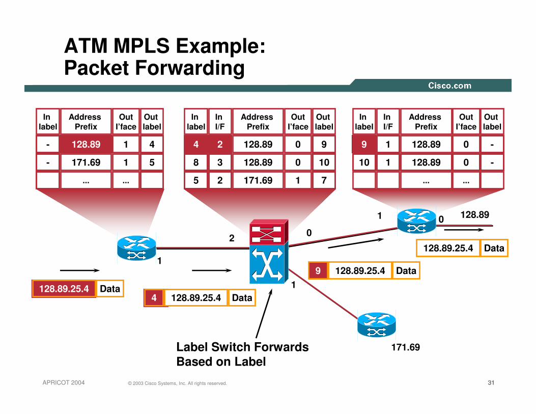
2
1
ATM MPLS Example: Packet Forwarding
128.89
171.69
1
0
1
128.89.25.4 Data4128.89.25.4 Data
128.89.25.4 Data
128.89.25.4 Data9
0
Label Switch Forwards Based on Label
In label
Address Prefix
128.89
171.69
...
OutI’face
1
1
...
Out label
In I/F
Address Prefix
128.89
128.89
171.69
OutI’face
0
0
1
Out label
In I/F
Address Prefix
128.89
...
OutI’face
0
...
Out label
In label
In label
1
1 128.89 0
-
-
9
10
9
10
7
2
3
2
4
8
5
4
5
-
-

323232© 2003 Cisco Systems, Inc. All rights reserved.APRICOT 2004
Why Multiple Labels with ATM?
• If didn’t allocate multiple labels:
Cells of different packets would have same label (VPI/VCI)
Egress router can’t reassemble packets
In label
5
8
...
Address Prefix
128.89
128.89
...
OutI/F
0
0
...
Out label
3
3
...
128.8933
8
55
55
8 8 8 33 33
Cells
Help!
In I/F
1
2
...
1
2
0Packet
Packet

333333© 2003 Cisco Systems, Inc. All rights reserved.APRICOT 2004
In label
5
8
...
Address Prefix
128.89
128.89
...
OutI/F
0
0
...
Out label
3
7
...
Multiple Labels
• Multiple labels enables edge router to reassemble packets correctly
128.8937
8
55
55
8 8 8 37 37
Cells
Much better!
In I/F
1
2
...
1
2
0Packet
Packet

343434© 2003 Cisco Systems, Inc. All rights reserved.APRICOT 2004
Label Distribution Protocol
• Label MergeDone by default for packet networks—unique label advertised per FEC
Requires VC merge for ATM networks

353535© 2003 Cisco Systems, Inc. All rights reserved.APRICOT 2004
LDP—Label Merge
Prefix 129.161/16
IGP—Equal Cost Multipath
Prefix 129.161/16
Labels for Prefix 129.161 Are Advertised Along both Paths

363636© 2003 Cisco Systems, Inc. All rights reserved.APRICOT 2004
VC Merge
• With ATM switch that can merge VC’s:Can reuse outgoing labelHardware prevents cell interleaveFewer labels required For very large networks
In label
5
8
...
Address Prefix
128.89
128.89
...
OutI/F
0
0
...
Out label
3
3
...
128.893
8
55
55
8 8 8 33 33
Cells
In I/F
1
2
...
1
2
0Packet
Packet 3

373737© 2003 Cisco Systems, Inc. All rights reserved.APRICOT 2004
LDP
• Neighbor discoveryDiscover directly attached Neighbors—pt-to-pt links (including Ethernet)Establish a sessionExchange prefix/FEC and label information
• Extended Neighbor DiscoveryEstablish peer relationship with another router that is not a neighborExchange FEC and label informationMay be needed to exchange service labels

383838© 2003 Cisco Systems, Inc. All rights reserved.APRICOT 2004
TDP and LDP
• Tag Distribution Protocol—Cisco proprietaryPre-cursor to LDPUsed for Cisco Tag Switching
• TDP and LDP supported on the same devicePer neighbor/link basis Per target basis
• LDP is a superset of TDP• Uses the same label/TAG• Has different message formats

393939© 2003 Cisco Systems, Inc. All rights reserved.APRICOT 2004
Configuring MPLS
Configures the use of LDP on all interfaces;Sets the default label distribution protocol for all interfaces to be LDP
Router# configure terminalRouter(config)# mpls label protocol ldp
StepStep 66
Configures the use of LDP for a specific interface; Sets the default label distribution protocol for the specified interface to be LDP, overriding any default set by the global mpls label protocol command
Router(config-if)# mpls label protocol ldp
StepStep 55
Configures MPLS hop-by-hop forwarding for a specified interface
Router(config-if)# mpls ipStepStep 44
Specifies the interface to configureRouter(config)# interface interface
StepStep 33
Configures Cisco Express ForwardingRouter(config)# ip cef [distributed]
StepStep 22
Enables configuration modeRouter# configure terminalStepStep 11

404040© 2003 Cisco Systems, Inc. All rights reserved.APRICOT 2004
Show Commands
Router# show mpls interfacesInterface IP Tunnel Operational Ethernet1/1/1 Yes (tdp) No No Ethernet1/1/2 Yes (tdp) Yes No Ethernet1/1/3 Yes (tdp) Yes Yes POS2/0/0 Yes (tdp) No No ATM0/0.1 Yes (tdp) No No (ATM labels) ATM3/0.1 Yes (ldp) No Yes (ATM labels) ATM0/0.2 Yes (tdp) No Yes
Router# show mpls ldp discoveryLocal LDP Identifier: 118.1.1.1:0 Discovery Sources: Interfaces: POS2/0 (ldp): xmit/recv LDP Id: 155.0.0.55:0 Tunnel1 (ldp): Targeted -> 133.0.0.33 Targeted Hellos: 118.1.1.1 -> 133.0.0.33 (ldp): active, xmit/recv LDP Id: 133.0.0.33:0 118.1.1.1 -> 168.7.0.16 (tdp): passive, xmit/recv TDP Id: 168.7.0.16:0
show mpls ip binding [vrf vpn-name] [network {mask | length} [longer-prefixes]][local-label {atm vpi vci | label [- label]}][remote-label {atm vpi vci | label [- label]}][neighbor address] [local][interface interface] [generic | atm]show mpls ip binding summary
Router# show mpls ip binding 194.44.44.0 24194.44.44.0/24 in label: 24 in vc label: 1/37 lsr: 203.0.7.7:2 ATM1/0.8 Active egress (vcd 56) out label: imp-null lsr: 155.0.0.55:0 inuse Router#
414141© 2003 Cisco Systems, Inc. All rights reserved.APRICOT 2004
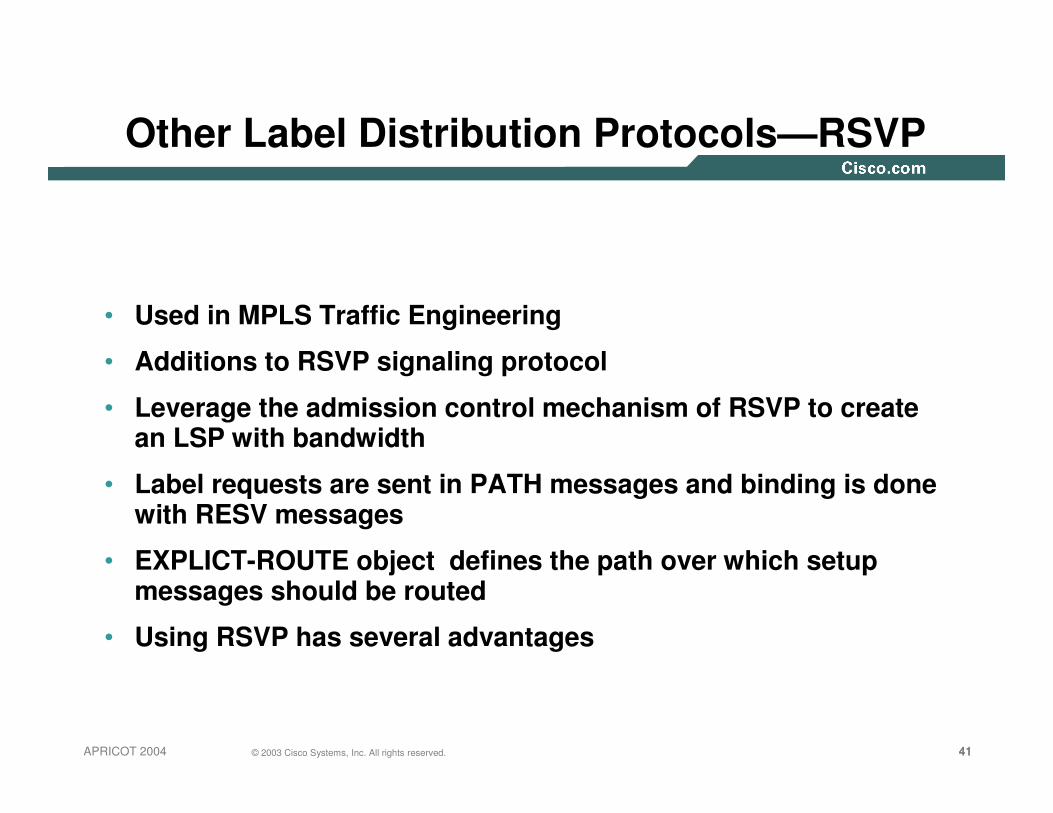
Other Label Distribution Protocols—RSVP
• Used in MPLS Traffic Engineering
• Additions to RSVP signaling protocol
• Leverage the admission control mechanism of RSVP to create an LSP with bandwidth
• Label requests are sent in PATH messages and binding is done with RESV messages
• EXPLICT-ROUTE object defines the path over which setup messages should be routed
• Using RSVP has several advantages

424242© 2003 Cisco Systems, Inc. All rights reserved.APRICOT 2004
Other Label Distribution Protocols—BGP
• Used in the context of MPLS VPNs
• Need multiprotocol extensions to BGP
• Routers need to be BGP peers
• Label mapping info carried as part of NLRI (Network Layer Reacheability Information)
434343© 2003 Cisco Systems, Inc. All rights reserved.APRICOT 2004
Basic MPLS Operation - recap
• IP packets are classified in FECs
Forwarding Equivalence Class
• A group of IP packets which are forwarded in the same manner
Over the same path
With the same forwarding treatment
• Packet forwarding consists on
Assign a packet to a FEC
Determine the next-hop of each FEC

444444© 2003 Cisco Systems, Inc. All rights reserved.APRICOT 2004
MPLS Control and Forwarding Planes
• Control plane used to distribute labels—BGP, LDP, RSVP• Forwarding plane consists of label imposition, swapping and disposition—no
matter what the control plane• Key: There is a separation of Control Plane and Forwarding Plane
Basic MPLS: destination-based unicast
Labels divorce forwarding from IP address
Many additional options for assigning labels
Labels define destination and service
Destination-based Unicast Routing
Destination-based Unicast Routing
IP Classof ServiceIP Class
of Service
ResourceReservation(e.g., RSVP)
ResourceReservation(e.g., RSVP)
Multicast Routing (PIM v2)
Multicast Routing (PIM v2)
Explicitand Static
Routes
Explicitand Static
Routes
Virtual Private
Networks
Virtual Private
Networks
Label Information Base (LIB)Label Information Base (LIB)
Per-Label Forwarding, Queuing, and Multicast MechanismsPer-Label Forwarding, Queuing, and Multicast Mechanisms

454545© 2003 Cisco Systems, Inc. All rights reserved.APRICOT 2004
Control and Forward Plane Separation
LFIB
Routing Process
MPLS Process
RIB
LIB
FIB
Route
Updates/
Adjacency
Label Bind
Updates/
Adjacency
IP TrafficMPLS Traffic
464646© 2003 Cisco Systems, Inc. All rights reserved.APRICOT 2004
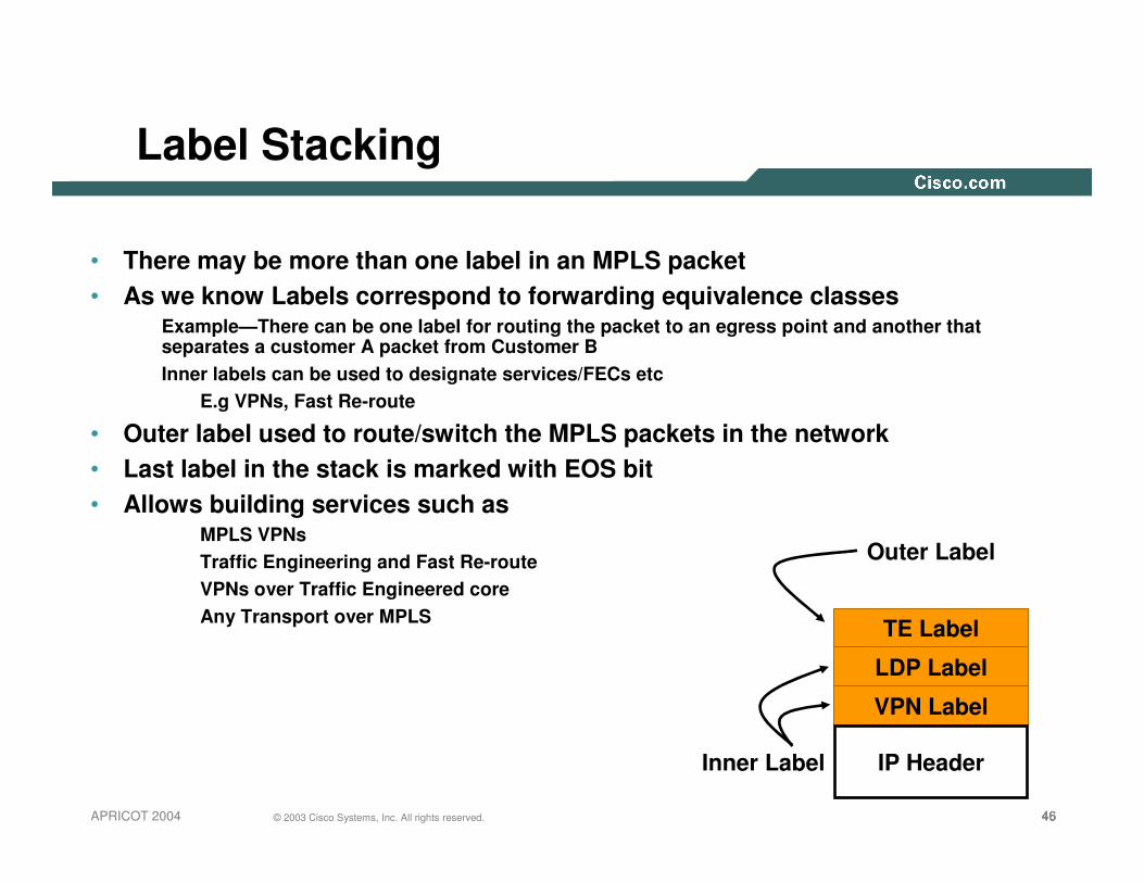
• There may be more than one label in an MPLS packet• As we know Labels correspond to forwarding equivalence classes
Example—There can be one label for routing the packet to an egress point and another that separates a customer A packet from Customer BInner labels can be used to designate services/FECs etc
E.g VPNs, Fast Re-route
• Outer label used to route/switch the MPLS packets in the network• Last label in the stack is marked with EOS bit• Allows building services such as
MPLS VPNsTraffic Engineering and Fast Re-routeVPNs over Traffic Engineered coreAny Transport over MPLS
Label Stacking
TE Label
LDP Label
VPN Label
Inner Label
Outer Label
IP Header
47© 2003 Cisco Systems, Inc. All rights reserved.APRICOT 2004
MPLS-Based Services
Azhar Sayeed

484848© 2003 Cisco Systems, Inc. All rights reserved.APRICOT 2004
MPLS and Its Applications
• Separate forwarding information (label) from the content of IP header
• Single forwarding paradigm (label swapping)—multiple routing paradigms
• Multiple link-specific realizations of the label swapping forwarding paradigm
• Flexibility of forming FECs
• Forwarding hierarchy via label stacking
• Traffic engineering
• Fast re-route
• “Hard” QoS support
• Integration with optical cross connects
• Scalable VPN

494949© 2003 Cisco Systems, Inc. All rights reserved.APRICOT 2004
Agenda
• MPLS and MPLS-VPN Overview
• MPLS-VPN Deployment Considerations
• Traffic Engineering
• Management Considerations and MPLS OAM
• Security Considerations
• Word About G-MPLS

505050© 2003 Cisco Systems, Inc. All rights reserved.APRICOT 2004
MPLS and MPLS-VPN Overview
505050© 2003 Cisco Systems, Inc. All rights reserved.Presentation_ID

51© 2003 Cisco Systems, Inc. All rights reserved.APRICOT 2004
MPLS VPNs
Layer 2 and Layer 3
Monique Morrow

525252© 2003 Cisco Systems, Inc. All rights reserved.APRICOT 2004
What Is a VPN ?
• VPN is a set of sites which are allowed to communicate with each other
• VPN is defined by a set of administrative policies
Policies determine both connectivity and QoS among sites
Policies established by VPN customers
Policies could be implemented completely by VPN Service Providers
Using BGP/MPLS VPN mechanisms
535353© 2003 Cisco Systems, Inc. All rights reserved.APRICOT 2004
What Is a VPN (Cont.)?
• Flexible inter-site connectivity
ranging from complete to partial mesh
• Sites may be either within the same or in different organizations
VPN can be either intranet or extranet
• Site may be in more than one VPN
VPNs may overlap
• Not all sites have to be connected to the same service provider
VPN can span multiple providers

545454© 2003 Cisco Systems, Inc. All rights reserved.APRICOT 2004
VPNs
• Layer 2 VPNsCustomer End points (CPE) connected via layer 2 such as Frame Relay DLCI, ATM VC or point to point connection
If it connects IP routers then peering or routing relationship is between the end points
Multiple logical connections (one with each end point)
• Layer 3 VPNsCustomer end points peer with provider routers
Single peering relationship
No mesh of connections
Provider network responsible for Distributing routing information to VPN sites
Separation of routing tables from one VPN to another

55© 2003 Cisco Systems, Inc. All rights reserved.APRICOT 2004
Layer 3 VPNs
Monique Morrow

565656© 2003 Cisco Systems, Inc. All rights reserved.APRICOT 2004
VPN A
VPN B
VPN CVPN A VPN B
VPN C
VPN A
VPN BVPN CVPN A
VPN C VPN BHosting
Multicast
VoIP
Intranet
Extranet
Service Provider Benefitsof MPLS-Based VPNs
Overlay VPN• Pushes content outside the network• Costs scale exponentially• Transport dependent• Groups endpoints, not groups• Complex overlay with QoS, tunnels, IP
MPLS-based VPNs• Enables content hosting inside
the network• “Flat” cost curve• Transport independent• Easy grouping of users and services• Enables QoS inside the VPNs

575757© 2003 Cisco Systems, Inc. All rights reserved.APRICOT 2004
Using Labels to Build an IP VPN
• The network distributes labels to each VPNOnly labels for other VPN members are distributedEach VPN is provisioned automatically by IP routing
• Privacy and QoS of ATM without tunnels or encryptionEach network is as secure as a Frame Relay connection
• One mechanism (labels) for QoS and VPNs—no tradeoffs
Cust ACust A Cust ACust A
Cust ACust A
Cust BCust B Cust BCust B
MPLSNetwork
A-----------
A-----------
B-----------
B-----------

585858© 2003 Cisco Systems, Inc. All rights reserved.APRICOT 2004
How Does It Work?
• Simple idea
Use a label to designate VPN prefix
Route that VPN packet to egress PE advertising that prefix
Use the IGP label to the VPN packet to the egress node
• How is it done?
Routers need to maintain separate VPN routing tables called VRFs(Virtual Routing and Forwarding Tables)
Routers then export and import routes using BGP extensions to identify and separate one VPNs routes from another
Routers then exchange labels for VPN routes in addition to IGP routes

595959© 2003 Cisco Systems, Inc. All rights reserved.APRICOT 2004
VRFs
• A VRF is associated to one or more interfaces on a router
• VRF is essentially a per-interface routing table and the necessary forwarding operations (CEF)
• Not virtual routers, just virtual routing and forwarding
• VRFs are IP only (no Appletalk-VRF, although in theory it’s certainly possible)

606060© 2003 Cisco Systems, Inc. All rights reserved.APRICOT 2004
VRFs
• Within a VRF, provider speaks a routing protocol with their customer
• Most protocols are supported
Static routes
RIP
BGP
EIGRP
OSPF
• No IS-IS support yet (have not seen the demand)
• No IGRP or EGP support either (same idea)
• Routes flow between VRF IGP/BGP and provider BGP (see VPNv4)

616161© 2003 Cisco Systems, Inc. All rights reserved.APRICOT 2004
Virtual Routing and Forwarding Instances
• Define a VRF for interface 0
• Define a different VRF for interface 1
• Packets will never go between int. 0 and 1 unless allowed by VRF policy
Will explain this policy in the next section
• No MPLS yet…
VPN-A
VPN-A
CECEVPN-B
VRF for VPN-A
VRF for VPN-B
CECE
146.12.7.0/24146.12.7.0/24
195.12.2.0/24
0
1

626262© 2003 Cisco Systems, Inc. All rights reserved.APRICOT 2004
Carrying VPN Routes in BGP
• VRFs by themselves are not all that useful
• Need some way to get the VRF routing information off the PE and to other Pes
• This is done with BGP

636363© 2003 Cisco Systems, Inc. All rights reserved.APRICOT 2004
Additions to BGP to Carry MPLS-VPN Info
• RD: Route Distinguisher
• VPNv4 address family
• RT: Route Target
• Label

646464© 2003 Cisco Systems, Inc. All rights reserved.APRICOT 2004
Route Distinguisher
• To differentiate 10.0.0.0/8 in VPN-A from 10.0.0.0/8 in VPN-B
• 64-bit quantity
• Configured as ASN:YY or IPADDR:YYAlmost everybody uses ASN
• Purely to make a route uniqueUnique route is now RD:Ipaddr (96 bits) plus a mask on the IPAddr portion
So customers don’t see each others routes
So route reflectors make a bestpath decision on something other than 32-bit network + 32-bit mask

656565© 2003 Cisco Systems, Inc. All rights reserved.APRICOT 2004
VPNv4
• In BGP for IP, 32-bit address + mask makes a unique announcement
• In BGP for MPLS-VPN, (64-bit RD + 32-bit address) + 32-bit mask makes a unique announcement
• Since the route encoding is different, need a different address family in BGP
• VPNv4 = VPN routes for IPv4As opposed to IPv4 or IPv6 or multicast-RPF, etc…
• VPNv4 announcement carries a label with the route“If you want to reach this unique address, get me packets with this label on them”

666666© 2003 Cisco Systems, Inc. All rights reserved.APRICOT 2004
Route Target
• To control policy about who sees what routes
• 64-bit quantity (2 bytes type, 6 bytes value)
• Carried as an extended community
• Typically written as ASN:YY
• Each VRF ‘imports’ and ‘exports’ one or more RTs
Exported RTs are carried in VPNv4 BGP
Imported RTs are local to the box
• A PE that imports an RT installs that route in its routing table

676767© 2003 Cisco Systems, Inc. All rights reserved.APRICOT 2004
VPN A/Site 1
VPN A/Site 2
VPN B/Site 2
VPN B/Site 1
CEA1
CEA3
CE1B1
CE2B1
PE3
P1
P2
P3
16.1/16
16.2/16
16.1/16 16.2/16RIPv2
OSPF
RIPv2
OSPF
RIPv2BGPPE1
PE2
CEB2
Putting It All Together—Control Plane
Step 2Step 2
VPN-IPv4Net=RD:16.1/16NH=PE1Route TargetLabel=42
Step 1Step 1IGP/EBGPNet=16.1/16 Step 4Step 4
IGP/EBGP Net=16.1/16
Step 3Step 3
Import Net=RD:16.1/16VPN ANH=PE1Label=42

686868© 2003 Cisco Systems, Inc. All rights reserved.APRICOT 2004
MPLS-VPN Packet Forwarding
• Between PE and CE, regular IP packets (for now)
• Within the provider network—label stackOuter label: “get this packet to the egress PE”
Inner label: “get this packet to the egress CE”

696969© 2003 Cisco Systems, Inc. All rights reserved.APRICOT 2004
Where Do Labels Come From?
• Within a single network, can use LDP or RSVP to distribute IGP labels
• LDP follows the IGP
• RSVP (for TE) deviates from IGP shortest path
• Which IGP label distribution method you use is independent of any VPN label distribution

707070© 2003 Cisco Systems, Inc. All rights reserved.APRICOT 2004
Control Plane Path
• RD—8 Byte field—assigned by provider—significant to the provider network only• VPNv4 Address: RD+VPN Prefix• Unique RD per VPN makes the VPNv4 address unique
PE P P PE
CECE
No Direct Peering between CEs
Routing Relationship
VPNv4 Routes Advertised via BGPLabels Exchanged via BGP
VPN A VPN A
IPv4 Route Exchange
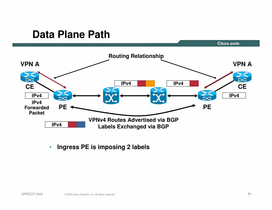
717171© 2003 Cisco Systems, Inc. All rights reserved.APRICOT 2004
CECE
Routing RelationshipVPN A VPN A
IPv4 Forwarded
Packet
Data Plane Path
• Ingress PE is imposing 2 labels
IPv4
IPv4
IPv4 IPv4
IPv4
VPNv4 Routes Advertised via BGPLabels Exchanged via BGP
PE PE
727272© 2003 Cisco Systems, Inc. All rights reserved.APRICOT 2004
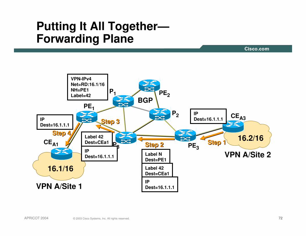
VPN A/Site 1
VPN A/Site 2
CEA1
CEA3
PE1
PE2
PE3
P1
P2
P3
16.1/16
16.2/16
BGP
Putting It All Together—Forwarding Plane
VPN-IPv4Net=RD:16.1/16NH=PE1Label=42
Step 1Step 1
IPDest=16.1.1.1
Label NDest=PE1
Label 42Dest=CEa1
IPDest=16.1.1.1
Step 2Step 2Label 42Dest=CEa1
IPDest=16.1.1.1
Step 3Step 3
Step 4Step 4
IPDest=16.1.1.1

737373© 2003 Cisco Systems, Inc. All rights reserved.APRICOT 2004
RFC 2547—MPLS VPNs
VRF
VRF
VRF
LDP LDPLDP
iBGP—VPNv4 Label Exchange
iBGP—VPNv4 iBGP—VPNv4PE
PE
PE
CE
CE
CECE
CECE
Overlapping Addresses AreMade Unique by Appending RD and Creating VPNv4 Addresses
CE

747474© 2003 Cisco Systems, Inc. All rights reserved.APRICOT 2004
MPLS-VPN Deployment Considerations
747474© 2003 Cisco Systems, Inc. All rights reserved.Presentation_ID
757575© 2003 Cisco Systems, Inc. All rights reserved.APRICOT 2004
Import/Export Policies
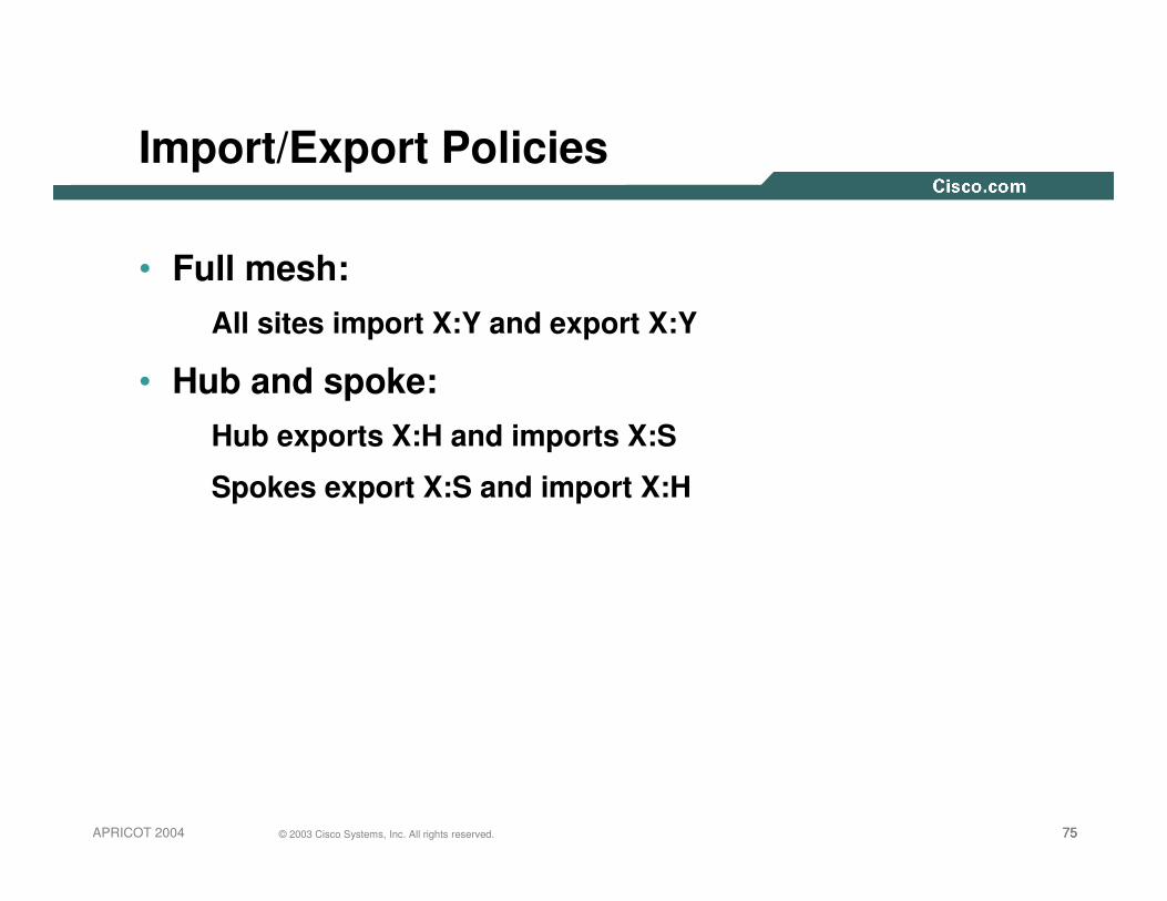
• Full mesh:All sites import X:Y and export X:Y
• Hub and spoke:Hub exports X:H and imports X:S
Spokes export X:S and import X:H
767676© 2003 Cisco Systems, Inc. All rights reserved.APRICOT 2004
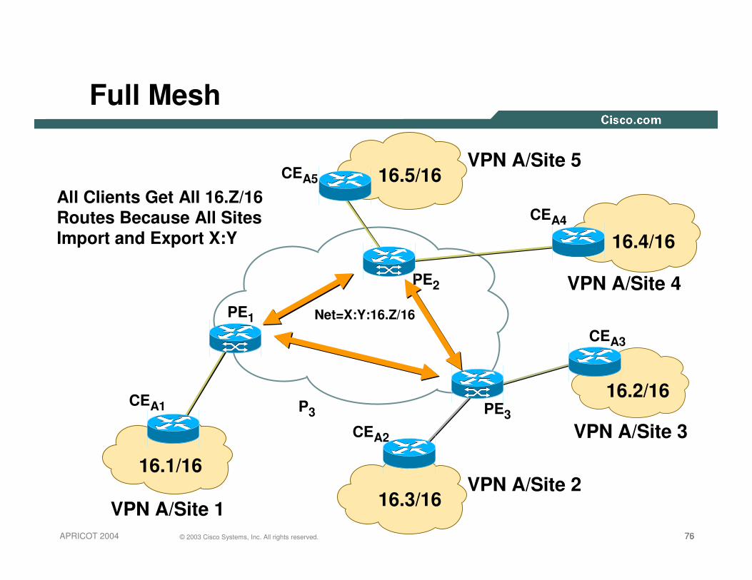
Full Mesh
VPN A/Site 1
VPN A/Site 5
VPN A/Site 3
VPN A/Site 4
VPN A/Site 2
CEA1
CEA2
CEA3
CEA5
PE1
PE2
PE3P3
16.1/16
16.2/16
CEA4
16.5/16
16.3/16
16.4/16
Net=X:Y:16.Z/16
All Clients Get All 16.Z/16Routes Because All SitesImport and Export X:Y

777777© 2003 Cisco Systems, Inc. All rights reserved.APRICOT 2004
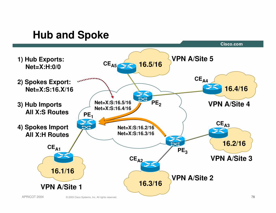
Hub and Spoke
VPN A/Site 1
VPN A/Site 5
VPN A/Site 3
VPN A/Site 4
CEA1
CEA2
CEA3
CEA5
PE1
PE2
PE3
16.1/16
16.2/16
CEA4
16.5/16
16.3/16
16.4/16
1) Hub Exports: Net=X:H:0/0
2) Spokes Export: Net=X:S:16.X/16
3) Hub Imports All X:S Routes
4) Spokes Import All X:H Routes
Net=X:H:0/0
VPN A/Site 2
787878© 2003 Cisco Systems, Inc. All rights reserved.APRICOT 2004
Hub and Spoke
VPN A/Site 1
VPN A/Site 5
VPN A/Site 3
VPN A/Site 4
CEA1
CEA2
CEA3
CEA5
PE1
PE2
PE3
16.1/16
16.2/16
CEA4
16.5/16
16.3/16
16.4/16
Net=X:S:16.5/16Net=X:S:16.4/16
Net=X:S:16.2/16Net=X:S:16.3/16
1) Hub Exports: Net=X:H:0/0
2) Spokes Export: Net=X:S:16.X/16
3) Hub Imports All X:S Routes
4) Spokes Import All X:H Routes
VPN A/Site 2

797979© 2003 Cisco Systems, Inc. All rights reserved.APRICOT 2004
All 16.Z/16 Routes
Hub and Spoke
VPN A/Site 1
VPN A/Site 5
VPN A/Site 3
VPN A/Site 4
CEA1
CEA2
CEA3
CEA5
PE1
PE2
PE3
16.1/16
16.2/16
CEA4
16.5/16
16.3/16
16.4/16
1) Hub Exports: Net=X:H:0/0
2) Spokes Export: Net=X:S:16.X/16
3) Hub Imports All X:S Routes
4) Spokes Import All X:H Routes
VPN A/Site 2

808080© 2003 Cisco Systems, Inc. All rights reserved.APRICOT 2004
Hub and Spoke
VPN A/Site 1
VPN A/Site 5
VPN A/Site 3
VPN A/Site 4
CEA1
CEA2
CEA3
CEA5
PE1
PE2
PE3
16.1/16
16.2/16
CEA4
16.5/16
16.3/16
16.4/160/0 0/0
0/0
0/0
VPN A/Site 2
1) Hub Exports: Net=X:H:0/0
2) Spokes Export: Net=X:S:16.X/16
3) Hub Imports All X:S Routes
4) Spokes Import All X:H Routes

818181© 2003 Cisco Systems, Inc. All rights reserved.APRICOT 2004
Things to Note
• Core does not run VPNv4 BGP!
Same principle can be used to run a BGP-free core for an IP network
• CE does not know it’s in an MPLS-VPN
• Outer label is from LDP/RSVP
Getting packet to egress PE is orthogonal to MPLS-VPN
• Inner label is from BGP
Inner label is there so the egress PE can have the same network in multiple VRFs
828282© 2003 Cisco Systems, Inc. All rights reserved.APRICOT 2004
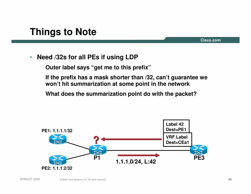
Things to Note
• Need /32s for all PEs if using LDP
Outer label says “get me to this prefix”
If the prefix has a mask shorter than /32, can’t guarantee we won’t hit summarization at some point in the network
What does the summarization point do with the packet?
P1 PE3
PE1: 1.1.1.1/32
1.1.1.0/24, L:42
Label 42Dest=PE1
VRF LabelDest=CEa1
PE2: 1.1.1.2/32
??
838383© 2003 Cisco Systems, Inc. All rights reserved.APRICOT 2004
Prerequisites
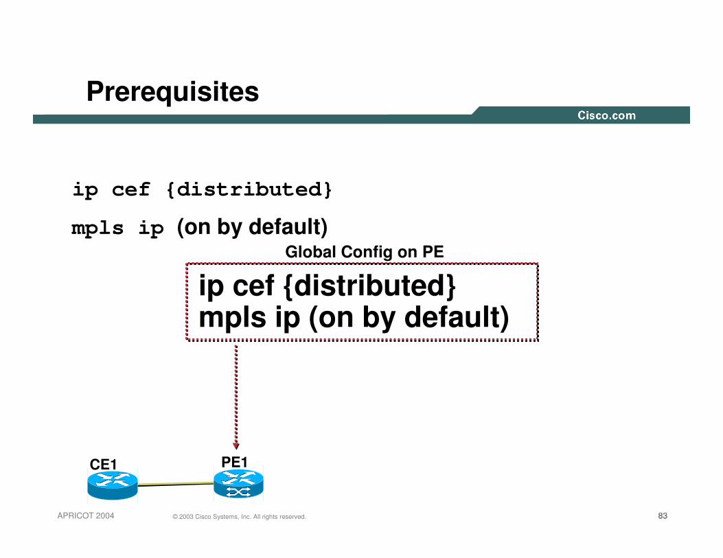
ip cef {distributed}
mpls ip (on by default)Global Config on PE
CE1 PE1
ip cef {distributed}mpls ip (on by default)

848484© 2003 Cisco Systems, Inc. All rights reserved.APRICOT 2004
Build a VRF
Global Config on PE
CE1 PE1
ip vrf foord 100:1
route-target import 247:1route-target export 247:1b

858585© 2003 Cisco Systems, Inc. All rights reserved.APRICOT 2004
Attach a VRF to a Customer Interface
interface Serial0
ip vrf forwarding foo
ip address 10.1.1.1 255.255.255.0
10.1.1.210.1.1.1
CE1 PE1

868686© 2003 Cisco Systems, Inc. All rights reserved.APRICOT 2004
Run an IGP within a VRF—RIP
router rip
address-family ipv4 vrf foo
version 2
no auto-summary
network 10.0.0.0
exit-address-family
CE1 PE110.1.1.2
10.1.1.1

878787© 2003 Cisco Systems, Inc. All rights reserved.APRICOT 2004
Run an IGP within a VRF—EIGRP
router eigrp 1
address-family ipv4 vrf test
network 10.1.1.0 0.0.0.255
autonomous-system 1
exit-address-family
CE1 PE110.1.1.2
10.1.1.1

888888© 2003 Cisco Systems, Inc. All rights reserved.APRICOT 2004
Run an IGP within a VRF—OSPF
router ospf 1 vrf test
network 10.1.1.0 0.0.0.255 area 0
CE1 PE110.1.1.2
10.1.1.1
898989© 2003 Cisco Systems, Inc. All rights reserved.APRICOT 2004
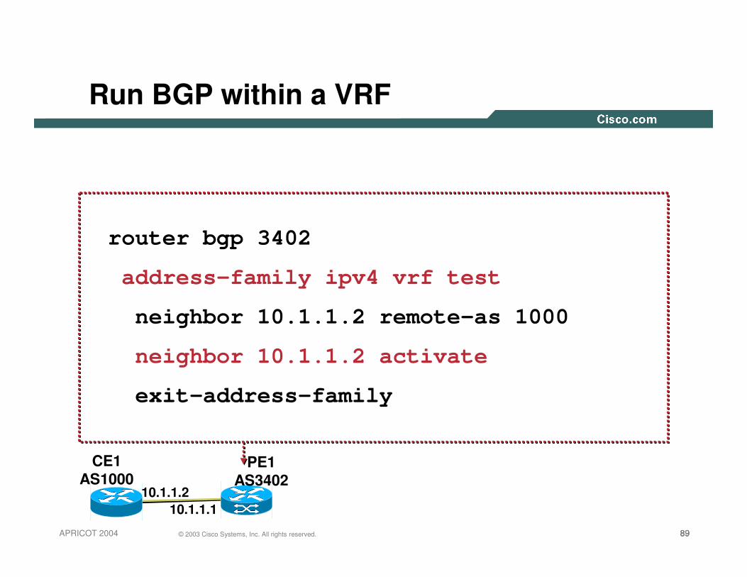
Run BGP within a VRF
router bgp 3402
address-family ipv4 vrf test
neighbor 10.1.1.2 remote-as 1000
neighbor 10.1.1.2 activate
exit-address-family
CE1AS1000
PE1AS3402
10.1.1.210.1.1.1
909090© 2003 Cisco Systems, Inc. All rights reserved.APRICOT 2004
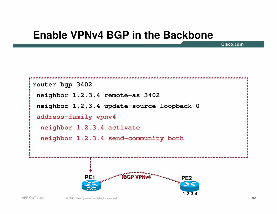
Enable VPNv4 BGP in the Backbone
router bgp 3402
neighbor 1.2.3.4 remote-as 3402
neighbor 1.2.3.4 update-source loopback 0
address-family vpnv4
neighbor 1.2.3.4 activate
neighbor 1.2.3.4 send-community both
PE1 PE2iBGP VPNv4iBGP VPNv4
1.2.3.4

919191© 2003 Cisco Systems, Inc. All rights reserved.APRICOT 2004
Get Routes from Customer Routing to VPNv4
• If CE routing is not BGP, need to redistribute into BGP
• NOTE: this means you *need* an IPv4 VRF BGP context to get routes into the PE backbone, even if you don’t have any BGP neighbors in the VRF
• IGP metric is usually carried as MED, unless changedEIGRP is an exception, carries the 5-part metric as BGP extended communities
CE1 PE1 PE2iBGP VPNv4iBGP VPNv4
1.2.3.4
Routes from CE1
router bgp 34032
neighbor 1.2.3.4 remote-as 3402
neighbor 1.2.3.4 update-source loopback 0
address-family ipv4 vrf test
redistribute {rip|connected|static|eigrp|ospf}
929292© 2003 Cisco Systems, Inc. All rights reserved.APRICOT 2004
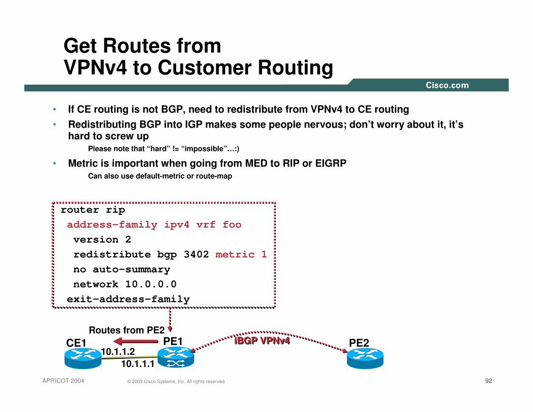
Get Routes from VPNv4 to Customer Routing
• If CE routing is not BGP, need to redistribute from VPNv4 to CE routing• Redistributing BGP into IGP makes some people nervous; don’t worry about it, it’s
hard to screw upPlease note that “hard” != “impossible”…:)
• Metric is important when going from MED to RIP or EIGRPCan also use default-metric or route-map
CE1 PE110.1.1.2
10.1.1.1
PE2iBGP VPNv4iBGP VPNv4Routes from PE2
router ripaddress-family ipv4 vrf fooversion 2redistribute bgp 3402 metric 1no auto-summarynetwork 10.0.0.0
exit-address-family

939393© 2003 Cisco Systems, Inc. All rights reserved.APRICOT 2004
Diagnostics on the PE
• Many commands have a ‘vrf’ keyword
Ping, traceroute, telnet, etc
Pretty much every diagnostic command that makes sense
ping vrf test 10.1.1.1
trace vrf test 10.1.1.1
telnet 10.1.1.1 /vrf test

949494© 2003 Cisco Systems, Inc. All rights reserved.APRICOT 2004
Diagnostics on the PE
…etc…
show ip route vrf test
show ip cef vrf test

959595© 2003 Cisco Systems, Inc. All rights reserved.APRICOT 2004
Route Reflectors
• Biggest scaling hurdle with MPLS-VPN is BGP
• Luckily, we have lots of experience scaling BGP
• Can use confederations or route reflectors
Confederations falling out of favor
• RRs make more sense when not every router needs all routes (i.e., Pes)
• Scaling is a little different
Currently ~120k Internet routes
Some customers are asking for 500k-1M VPNv4 routes
Largest in reality is closer to 200k-250k, but be prepared

969696© 2003 Cisco Systems, Inc. All rights reserved.APRICOT 2004
Route Reflectors
• Full iBGP mesh is a lot of neighborsto maintain on every router
• N^2 provisioning when a PE is added, and VPN networks are growing constantly
• Route Reflector takes routes from neighbors, gives them to other neighbors
• Can build a dedicated RR that isn’t used for forwarding, but which can hold lots of routes
• 1GB Memory, ~1,000,000 routes
Route Reflector
979797© 2003 Cisco Systems, Inc. All rights reserved.APRICOT 2004
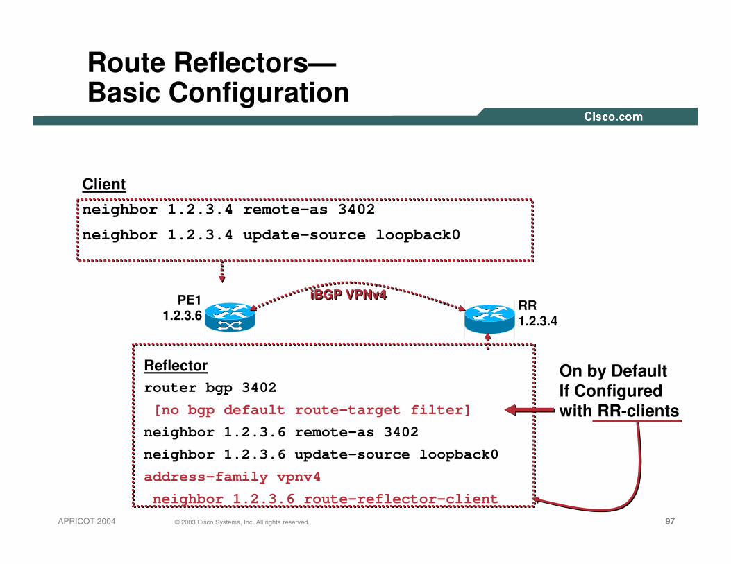
Route Reflectors—Basic Configuration
Clientneighbor 1.2.3.4 remote-as 3402
neighbor 1.2.3.4 update-source loopback0
Reflectorrouter bgp 3402
[no bgp default route-target filter]
neighbor 1.2.3.6 remote-as 3402
neighbor 1.2.3.6 update-source loopback0
address-family vpnv4
neighbor 1.2.3.6 route-reflector-client
iBGP VPNv4iBGP VPNv4PE11.2.3.6
RR1.2.3.4
On by DefaultIf Configuredwith RR-clients
989898© 2003 Cisco Systems, Inc. All rights reserved.APRICOT 2004
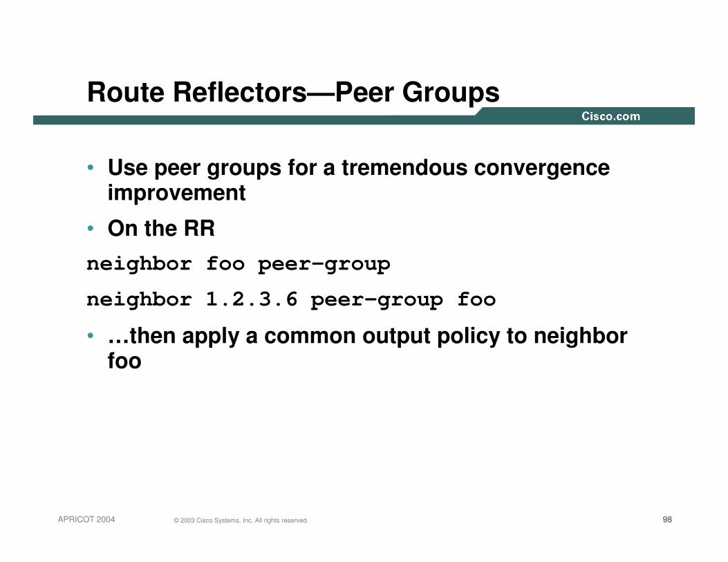
Route Reflectors—Peer Groups
• Use peer groups for a tremendous convergence improvement
• On the RRneighbor foo peer-group
neighbor 1.2.3.6 peer-group foo
• …then apply a common output policy to neighbor foo
999999© 2003 Cisco Systems, Inc. All rights reserved.APRICOT 2004
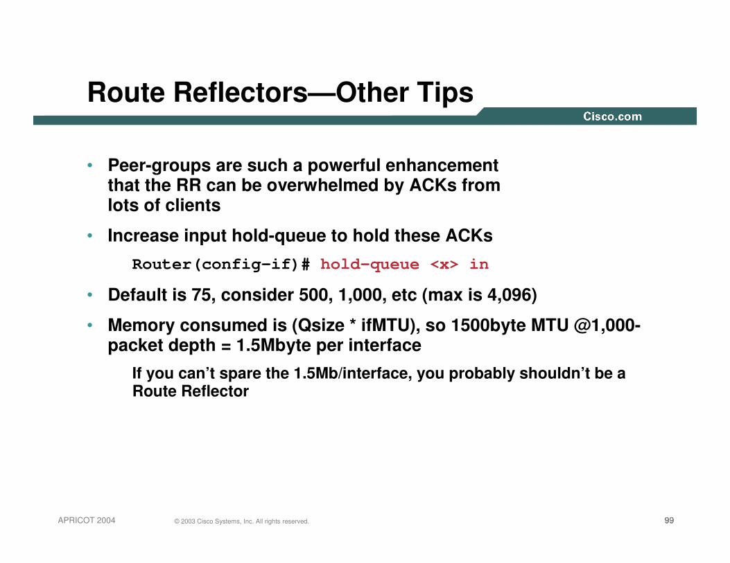
Route Reflectors—Other Tips
• Peer-groups are such a powerful enhancement that the RR can be overwhelmed by ACKs from lots of clients
• Increase input hold-queue to hold these ACKs
Router(config-if)# hold-queue <x> in
• Default is 75, consider 500, 1,000, etc (max is 4,096)
• Memory consumed is (Qsize * ifMTU), so 1500byte MTU @1,000-packet depth = 1.5Mbyte per interface
If you can’t spare the 1.5Mb/interface, you probably shouldn’t be a Route Reflector

100100100© 2003 Cisco Systems, Inc. All rights reserved.APRICOT 2004
Route Reflectors—Other Tips
• TCP MSS (max segment size) is 536 by default
• All backbone links now are MTU 1500 or higher (most ~4k)
• ‘ip tcp path-mtu-discovery’ to increase tcp MSS to fix in MTU
• Benefit: get BGP routes to peers faster, less protocol overhead

101101101© 2003 Cisco Systems, Inc. All rights reserved.APRICOT 2004
Advanced Services: Carrier Supporting Carrier
• RFC3107 defines a way to exchange a label with an IPv4 (not VPNv4) BGP route
• This is useful to exchange label reachability for IPv4 prefixes between ASes
• Also used in Carrier’s Carrier and Inter-AS
• Under IPv4 (or IPv4 vrf) address-family:
neighbor 1.2.3.4 send-label

102102102© 2003 Cisco Systems, Inc. All rights reserved.APRICOT 2004
Carrier’s Carrier: The Problem
• MPLS-VPN works well for carrying customer IGPs
• Platforms, network scale to N*O(IGP) routes
• What if the CE wants the PE to carry all their BGP routes?
• Or if CE wants to run their own VPN service?

103103103© 2003 Cisco Systems, Inc. All rights reserved.APRICOT 2004
Carrier’s Carrier: The Problem (Internet)
ISP A/Site 1MPLS-VPN Provider
ISP A/Site 2MPLS-VPN Provider
CEA1
CEA3
PE3
P1
BGP
iBGP IPv4
Step 1Step 1
IPDest=Internet
Internet
PE1
PE2
Carrier

104104104© 2003 Cisco Systems, Inc. All rights reserved.APRICOT 2004
Carrier’s Carrier: The Problem (VPN)
ISP A/Site 1MPLS-VPN Provider
ISP A/Site 2MPLS-VPN Provider
CEA1
CEA3
Label (iBGP VPnv4)Dest=VRF A
iBGP VPNv4
Step 1Step 1
IPDest=1.2.3.4
VRF A1.2.3.0/24
PE3
P1
BGPPE1
PE2
Carrier

105105105© 2003 Cisco Systems, Inc. All rights reserved.APRICOT 2004
PE3
P1
BGPPE1
PE2
Carrier
Carrier’s Carrier: The Solution (Internet)
ISPA/Site 1MPLS-VPN Provider
ISP A/Site 2MPLS-VPN Provider
CEA1
CEA3IPDest=Internet
Step 1Step 1
Label (LDP/BGP+Label)Dest=CEa1
Step 3Step 3
IPDest=Internet
Label (VPNv4)Dest=CEa1
Step 4Step 4
IPDest=Internet
Internet
Step 2Step 2
IPDest=Internet
Label (VPNv4/IBGP)Dest=CEa1
Label (LDP/TE)Dest=PE1

106106106© 2003 Cisco Systems, Inc. All rights reserved.APRICOT 2004
PE3
P1
BGPPE1
PE2
Carrier
Carrier’s Carrier: The Solution (VPN)
ISP A/Site 1MPLS-VPN Provider
ISPA/Site 2MPLS-VPN Provider
CEA1
CEA3
Step 1Step 1
Step 2Step 2Step 3Step 3
Step 4Step 4
IPDest=VPN1-Cust
Label (iBGP VPNv4)Dest=VPN1
Label (LDP/BGP)Dest=CEa1
IPDest=VPN1-Cust
Label (VPNv4)Dest=VPN1
Label (VPnv4)Dest=CEa1
IPDest=VPN1-Cust
Label (VPNv4)Dest=VPN1
VPN1-CustIPDest=VPN1-Cust
Label (VPNv4)Dest=VPN1
Label (VPnv4)Dest=CEa1
Label (LDP/TE)Dest=PE1

107107107© 2003 Cisco Systems, Inc. All rights reserved.APRICOT 2004
2547 Intra-AS Connectivity Model
• A VPN is a collection of sites sharing common routing informationsame set of routes within the RIB/FIB
• A site may obtain Intranet or Extranet connectivitythrough sharing of routing information
• A VPN can be thought of as a Closed User Group (CUG) or community of interest
• Layer-3 forwarding between VPN sites

108108108© 2003 Cisco Systems, Inc. All rights reserved.APRICOT 2004
Distribution of local routing information
• PE routers distribute local VPN information across the 2547 backbonethrough the use of MP-BGP & redistribution from VRFs
receiving PE imports routes into attached VRFs
BGP-4BGP-4 2547bis Backbone
VRF VPN-A
VPN-A San Jose
VRF VPN-A
VPN-A New York
109109109© 2003 Cisco Systems, Inc. All rights reserved.APRICOT 2004
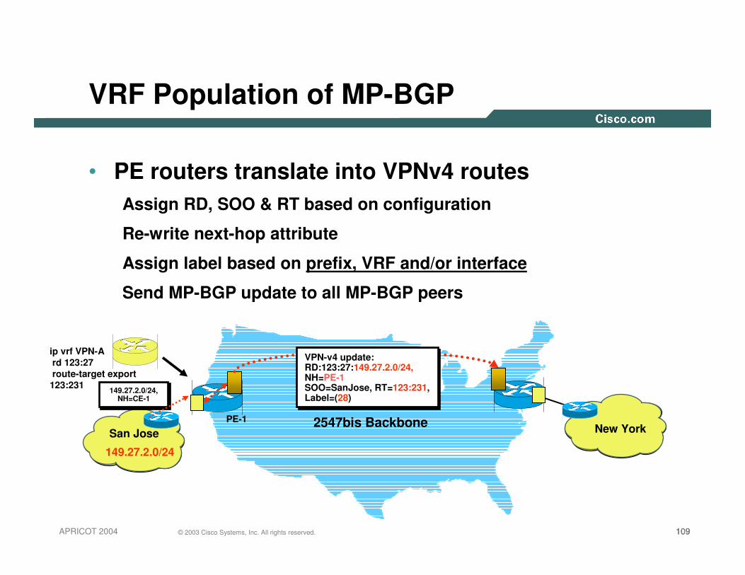
ip vrf VPN-Ard 123:27route-target export 123:231
VRF Population of MP-BGP
• PE routers translate into VPNv4 routesAssign RD, SOO & RT based on configuration
Re-write next-hop attribute
Assign label based on prefix, VRF and/or interface
Send MP-BGP update to all MP-BGP peers
2547bis BackboneSan Jose New York
149.27.2.0/24
149.27.2.0/24,NH=CE-1
149.27.2.0/24,NH=CE-1
VPN-v4 update:RD:123:27:149.27.2.0/24,NH=PE-1SOO=SanJose, RT=123:231, Label=(28)
VPN-v4 update:RD:123:27:149.27.2.0/24,NH=PE-1SOO=SanJose, RT=123:231, Label=(28)
PE-1
110110110© 2003 Cisco Systems, Inc. All rights reserved.APRICOT 2004
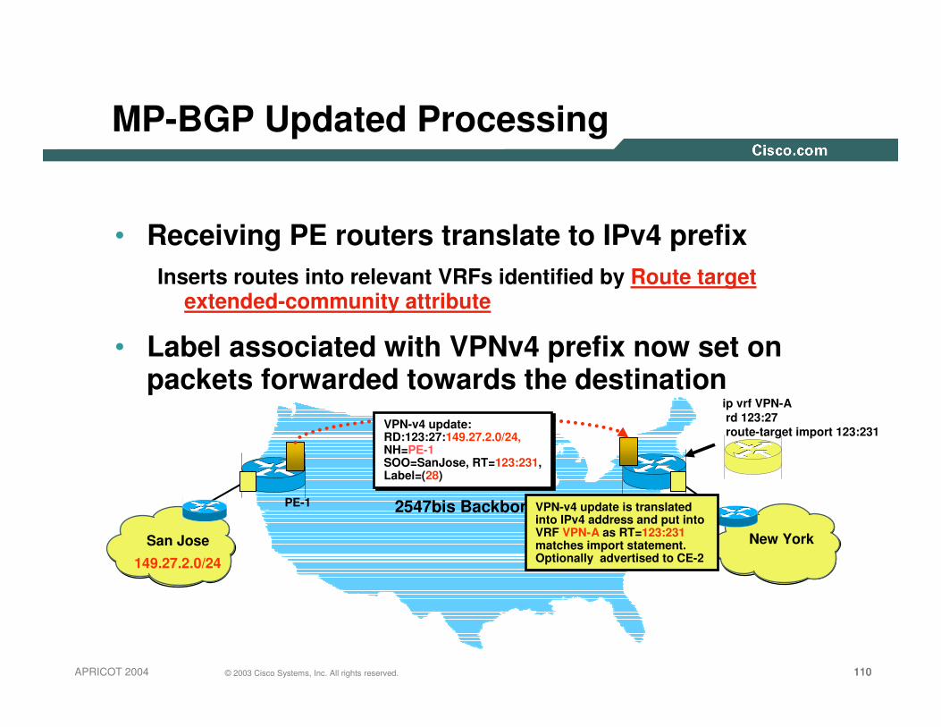
MP-BGP Updated Processing
• Receiving PE routers translate to IPv4 prefixInserts routes into relevant VRFs identified by Route target
extended-community attribute
• Label associated with VPNv4 prefix now set on packets forwarded towards the destination
2547bis Backbone
San Jose New York
149.27.2.0/24
VPN-v4 update:RD:123:27:149.27.2.0/24,NH=PE-1SOO=SanJose, RT=123:231, Label=(28)
VPN-v4 update:RD:123:27:149.27.2.0/24,NH=PE-1SOO=SanJose, RT=123:231, Label=(28)
PE-1 VPN-v4 update is translated into IPv4 address and put into VRF VPN-A as RT=123:231 matches import statement. Optionally advertised to CE-2
ip vrf VPN-Ard 123:27route-target import 123:231
111111111© 2003 Cisco Systems, Inc. All rights reserved.APRICOT 2004
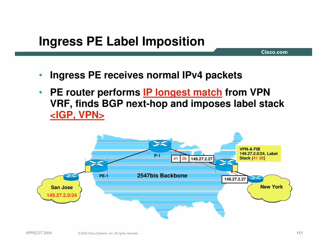
Ingress PE Label Imposition
• Ingress PE receives normal IPv4 packets
• PE router performs IP longest match from VPN VRF, finds BGP next-hop and imposes label stack <IGP, VPN>
2547bis Backbone
San Jose New York
149.27.2.0/24
PE-1
VPN-A FIB149.27.2.0/24, Label Stack {41 28}
149.27.2.27
2841 149.27.2.27P-1
112112112© 2003 Cisco Systems, Inc. All rights reserved.APRICOT 2004
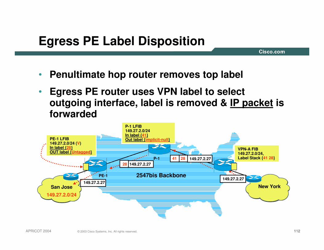
Egress PE Label Disposition
• Penultimate hop router removes top label
• Egress PE router uses VPN label to select outgoing interface, label is removed & IP packet is forwarded
2547bis Backbone
San Jose New York
149.27.2.0/24
PE-1
VPN-A FIB149.27.2.0/24, Label Stack {41 28}
149.27.2.27
2841 149.27.2.27P-1
P-1 LFIB149.27.2.0/24 In label {41} Out label {implicit-null}PE-1 LFIB
149.27.2.0/24 (V) In label {28}OUT label {Untagged}
28 149.27.2.27
149.27.2.27

113113113© 2003 Cisco Systems, Inc. All rights reserved.APRICOT 2004
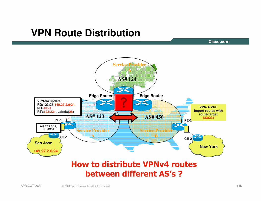
VPN Connectivity between AS#s
• VPN sites may be geographically dispersedRequiring connectivity to multiple providers, or different
regions of the same provider
• Transit traffic between VPN sites may pass through multiple AS#sThis implies that routing information MUST be exchanged
across AS#s
• Distinction drawn between Inter-Provider & Inter-AS

114114114© 2003 Cisco Systems, Inc. All rights reserved.APRICOT 2004
Inter-Provider Vs. Inter-AS
Inter-Provider Connectivity
SF POP
LA POP
NY POP
RRRR
RRRR
ASBR
RR RR
WASH POP
RRRR
ASBR
Service Provider A
ASBR
ASBR
Service Provider B

115115115© 2003 Cisco Systems, Inc. All rights reserved.APRICOT 2004
Inter-Provider Vs Inter-AS
Inter-AS Connectivity
Service Provider A
European Region
NY POP
WASH POP
ASBR
ASBR
LON POP
Service Provider A
North America Region
116116116© 2003 Cisco Systems, Inc. All rights reserved.APRICOT 2004
VPN Route Distribution
PE-1
Edge Router
CE-1
149.27.2.0/24
VPN-A VRFImport routes with
route-target 123:231
���������������� ���������������������������������
AS# 123 AS# 456
VPN-v4 update:RD:123:27:149.27.2.0/24,NH=PE-1RT=123:231, Label=(28)
VPN-v4 update:RD:123:27:149.27.2.0/24,NH=PE-1RT=123:231, Label=(28)
San Jose
149.27.2.0/24,NH=CE-1
149.27.2.0/24,NH=CE-1
New York
CE-2
PE-2
Service Provider A
Service Provider B
AS# 124
Service Provider A
Edge Router
117117117© 2003 Cisco Systems, Inc. All rights reserved.APRICOT 2004
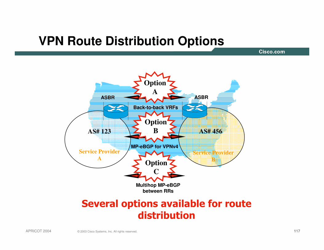
VPN Route Distribution Options
ASBR ASBR
������������������������������������������
AS# 123 AS# 456
Multihop MP-eBGPbetween RRs
Back-to-back VRFs
MP-eBGP for VPNv4
Option A
Option B
Option C
Service Provider A
Service Provider B

118118118© 2003 Cisco Systems, Inc. All rights reserved.APRICOT 2004
Option A – Back-to-back VRFs
• 2547 providers exchange routes between ASBRs over VRF interfacesHence ASBR is known as a PE-ASBR
• Each PE-ASBR router treats the other as a CE routerAlthough both provider interfaces are associated with a VRF
• Provider edge routers are gateways used for VPNv4 route exchange
• PE-ASBR link may use any PE-CE routing protocol
119119119© 2003 Cisco Systems, Inc. All rights reserved.APRICOT 2004
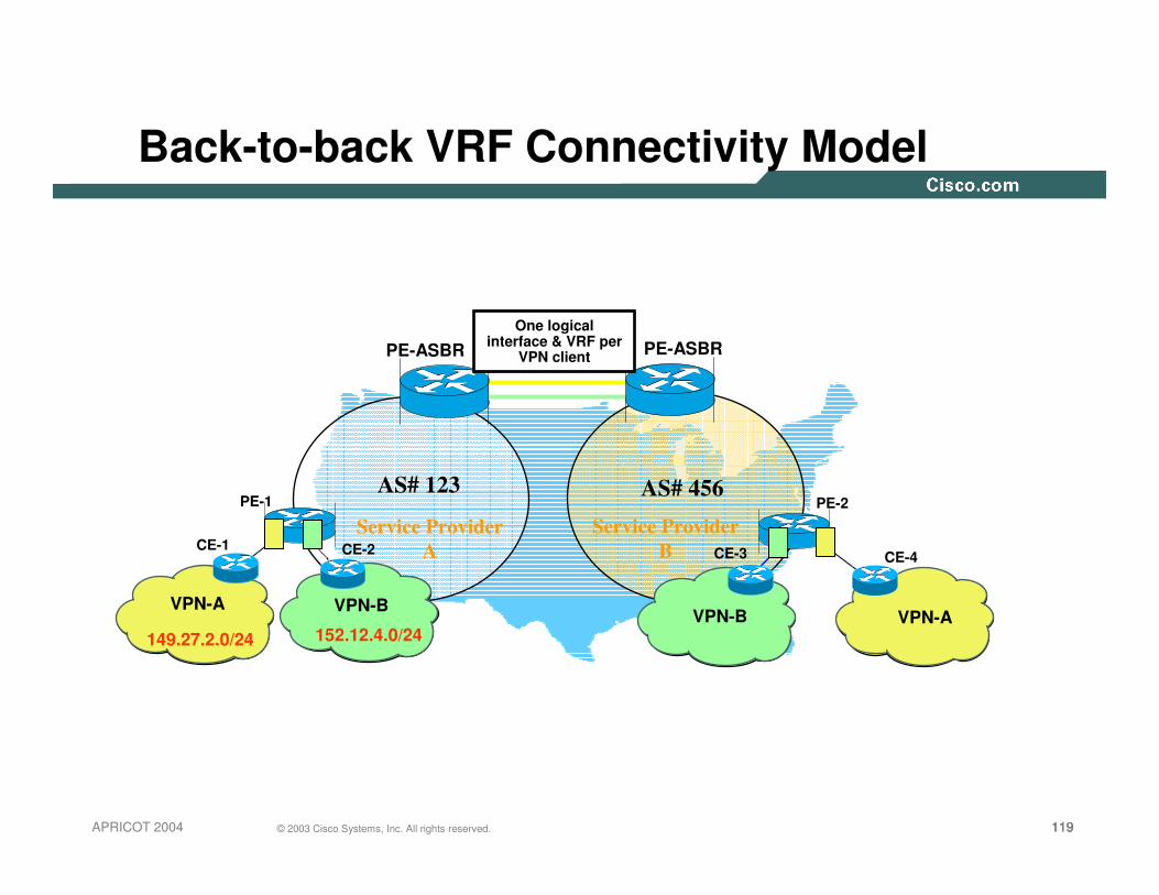
Back-to-back VRF Connectivity Model
PE-1
PE-ASBR PE-ASBR
CE-1
149.27.2.0/24
AS# 123 AS# 456
VPN-AVPN-A
CE-4
PE-2
VPN-B
CE-2
152.12.4.0/24
One logical interface & VRF per
VPN client
CE-3
VPN-B
Service Provider A
Service Provider B

120120120© 2003 Cisco Systems, Inc. All rights reserved.APRICOT 2004
Back-to-back Prefix Distribution
PE-1
PE-ASBR1 PE-ASBR2
AS# 123 AS# 456PE-2
VPN-B
CE-2
152.12.4.0/24
CE-3
VPN-B
152.12.4.0/24,NH=CE-2
152.12.4.0/24,NH=CE-2
VPN-v4 update:RD:123:27:152.12.4.0/24,NH=PE-1RT=123:222, Label=(29)
VPN-v4 update:RD:123:27:152.12.4.0/24,NH=PE-1RT=123:222, Label=(29)
VPN-B VRFImport routes with
route-target 123:222
BGP, OSPF, RIPv2 152.12.4.0/24 NH=PE-ASBR1
BGP, OSPF, RIPv2 152.12.4.0/24 NH=PE-ASBR1
VPN-v4 update:RD:123:27:152.12.4.0/24,NH=PE-ASBR-2RT=456:222, Label=(92)
VPN-v4 update:RD:123:27:152.12.4.0/24,NH=PE-ASBR-2RT=456:222, Label=(92)
VPN-B VRFImport routes with
route-target 456:222
152.12.4.0/24,NH=PE-2
152.12.4.0/24,NH=PE-2
Service Provider A
Service Provider B

121121121© 2003 Cisco Systems, Inc. All rights reserved.APRICOT 2004
Back-to-back Packet Flow
PE-1
PE-ASBR1 PE-ASBR2
AS# 123 AS# 456PE-2
VPN-B
CE-2
152.12.4.0/24
CE-3
VPN-B
152.12.4.1
LDP PE-ASBR-2 Label 92
152.12.4.1152.12.4.1
LDP PE-1 Label 29
152.12.4.1
152.12.4.1
Service Provider A
Service Provider B
122122122© 2003 Cisco Systems, Inc. All rights reserved.APRICOT 2004
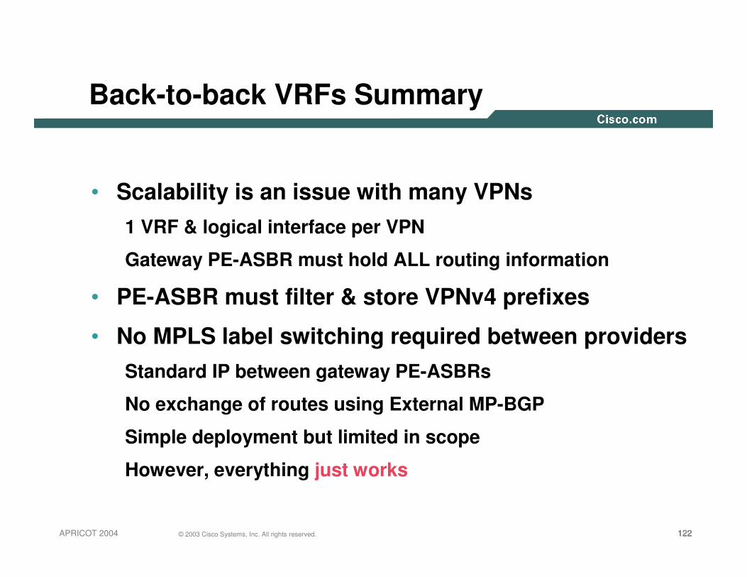
• Scalability is an issue with many VPNs1 VRF & logical interface per VPN
Gateway PE-ASBR must hold ALL routing information
• PE-ASBR must filter & store VPNv4 prefixes
• No MPLS label switching required between providersStandard IP between gateway PE-ASBRs
No exchange of routes using External MP-BGP
Simple deployment but limited in scope
However, everything just works
Back-to-back VRFs Summary

123123123© 2003 Cisco Systems, Inc. All rights reserved.APRICOT 2004
Option B – External MP-BGP
• Gateway ASBRs exchange VPNv4 routes directlyExternal MP-BGP for VPNv4 prefix exchange. No LDP/IGP
• BGP next-hop set to advertising ASBRNext-hop/labels are rewritten when advertised across ASBR-
ASBR link
• ASBR stores all VPN routes that need to be exchangedBut only within the BGP table. No VRFs. Labels are populated
into LFIB at ASBR

124124124© 2003 Cisco Systems, Inc. All rights reserved.APRICOT 2004
Label allocation at receiving PE-ASBR
• Receiving gateway ASBR may allocate new labelControlled by configuration of next-hop-self
LFIB holds new label allocation
• Receiving ASBR automatically creates a /32 host route for its ASBR neighborWhich must be advertised into receiving IGP if next-hop-self
is not in operation (to maintain the LSP)

125125125© 2003 Cisco Systems, Inc. All rights reserved.APRICOT 2004
External MP-BGP Connectivity Model
PE-1
ASBR-1 ASBR-2
CE-1
149.27.2.0/24
AS# 123 AS# 456
VPN-AVPN-A
CE-4
PE-2
VPN-B
CE-2
152.12.4.0/24
CE-3
VPN-B
Label exchange between Gateway
ASBR routers using MP-eBGP
External MP-BGP for VPNv4
Service Provider A
Service Provider B
126126126© 2003 Cisco Systems, Inc. All rights reserved.APRICOT 2004
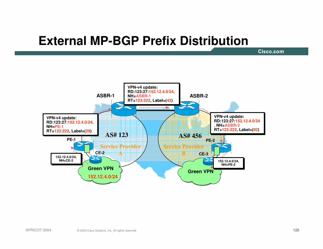
External MP-BGP Prefix Distribution
PE-1
ASBR-1 ASBR-2
AS# 123 AS# 456PE-2
Green VPN
CE-2
152.12.4.0/24
CE-3
Green VPN
152.12.4.0/24,NH=CE-2
152.12.4.0/24,NH=CE-2
VPN-v4 update:RD:123:27:152.12.4.0/24,NH=PE-1RT=123:222, Label=(29)
VPN-v4 update:RD:123:27:152.12.4.0/24,NH=PE-1RT=123:222, Label=(29)
VPN-v4 update:RD:123:27:152.12.4.0/24, NH=ASBR-2RT=123:222, Label=(92)
VPN-v4 update:RD:123:27:152.12.4.0/24, NH=ASBR-2RT=123:222, Label=(92)
152.12.4.0/24,NH=PE-2
152.12.4.0/24,NH=PE-2
VPN-v4 update:RD:123:27:152.12.4.0/24,NH=ASBR-1RT=123:222, Label=(42)
VPN-v4 update:RD:123:27:152.12.4.0/24,NH=ASBR-1RT=123:222, Label=(42)
Service Provider A
Service Provider B

127127127© 2003 Cisco Systems, Inc. All rights reserved.APRICOT 2004
External MP-BGP Packet Flow
PE-1
ASBR-1 ASBR-2
AS# 123 AS# 456PE-2
Green VPN
CE-2
152.12.4.0/24
CE-3
Green VPN
152.12.4.1
LDP PE-1 Label 29
152.12.4.1
152.12.4.1
LDP PE-ASBR-2 Label 92
152.12.4.1
152.12.4.192
42 152.12.4.1
29 152.12.4.1
Service Provider A
Service Provider B
128128128© 2003 Cisco Systems, Inc. All rights reserved.APRICOT 2004
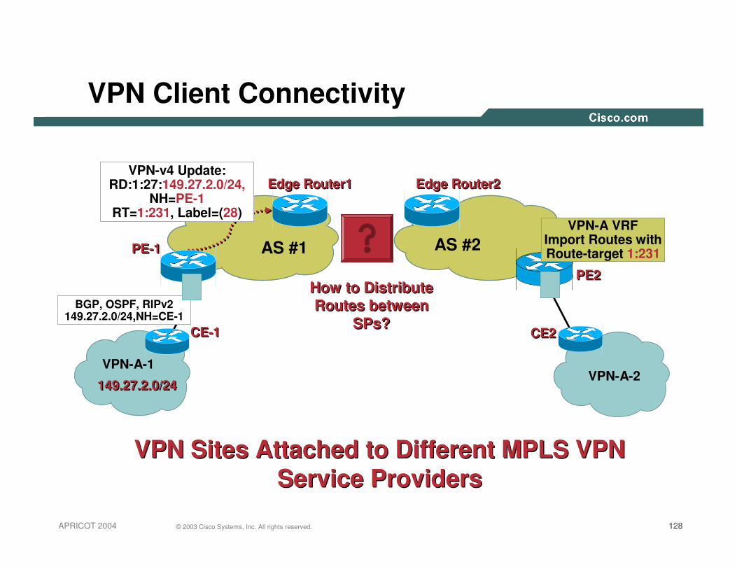
VPN Client Connectivity
VPN-A-1VPN-A-2
PE-1PE-1
PE2PE2
CE2 CE2
Edge Router1Edge Router1 Edge Router2Edge Router2
CE-1 CE-1
VPN Sites Attached to Different MPLS VPN Service Providers
VPN Sites Attached to Different MPLS VPN Service Providers
AS #1 AS #2
149.27.2.0/24149.27.2.0/24
VPN-A VRFImport Routes withRoute-target 1:231
How to Distribute Routes between
SPs?
How to Distribute Routes between
SPs?
VPN-v4 Update:RD:1:27:149.27.2.0/24,
NH=PE-1RT=1:231, Label=(28)
BGP, OSPF, RIPv2 149.27.2.0/24,NH=CE-1

129129129© 2003 Cisco Systems, Inc. All rights reserved.APRICOT 2004
External MP-BGP Summary
• Scalability less of an issue when compared to back-to-back VRF connectivityOnly 1 interface required between ASBR routers
No VRF requirement on any ASBR router
• Automatic route filtering must be disabledHence filtering on RT values essential
Import of routes into VRFs is NOT required (reduced memory impact)
• Label switching required between ASBRs

130130130© 2003 Cisco Systems, Inc. All rights reserved.APRICOT 2004
External MP-BGP Summary (Cont).
• Preferred option for Inter-Provider connectivityNo IP prefix exchange required between providers
Security is tighter
Peering agreements specify VPN membership
131131131© 2003 Cisco Systems, Inc. All rights reserved.APRICOT 2004
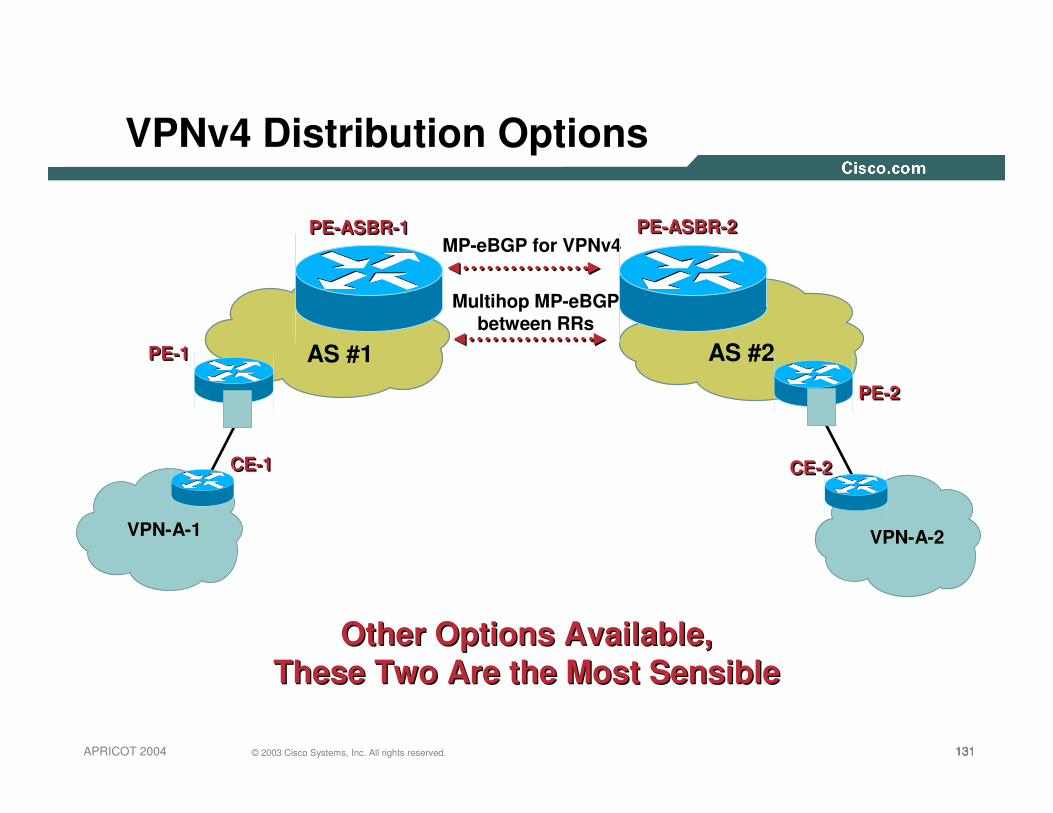
VPNv4 Distribution Options
PE-1PE-1
PE-2PE-2
CE-2 CE-2
MP-eBGP for VPNv4
Multihop MP-eBGPbetween RRs
Other Options Available, These Two Are the Most Sensible
Other Options Available, These Two Are the Most Sensible
AS #1 AS #2
PE-ASBR-1PE-ASBR-1 PE-ASBR-2PE-ASBR-2
CE-1 CE-1
VPN-A-1 VPN-A-2

132132132© 2003 Cisco Systems, Inc. All rights reserved.APRICOT 2004
ASBR Router Protection/Filtering
• MP-eBGP session is authenticated with MD5Potentially also IPSec in the data plane
• Routing updates filtered on ingress based on extended communitiesBoth from internal RRs and external peerings
ORF used between ASBRs and RRs.
Maximum-prefix on MP-BGP session
• Per-interface label space for external facing links to avoid label spoofing

133133133© 2003 Cisco Systems, Inc. All rights reserved.APRICOT 2004
Option C – Multihop MP-eBGP between RRs
• 2547 providers exchange VPNv4 prefixes via RRsRequires multihop MP-eBGP session
• Next-hop-self MUST be disabled on the RRsPreserves next-hop/label as allocated by originating PE router
• Providers exchange IPv4 routes with labels between directly connected ASBRs using External BGPOnly PE router BGP next-hop addresses exchanged
RFC3107 "Carrying Label Information in BGP-4"

134134134© 2003 Cisco Systems, Inc. All rights reserved.APRICOT 2004
RFC3107 – Carrying labels with BGP-4
MP_REACH_NLRI Attribute MP_REACH_NLRI Attribute (Specified in RFC 2858)(Specified in RFC 2858)
Prefix plus MPLS label Prefix plus MPLS label (Specified in RFC 3107)(Specified in RFC 3107)
0 1 2 3
0 1 2 3 4 5 6 7 8 9 0 1 2 3 4 5 6 7 8 9 0 1 2 3 4 5 6 7 8 9 0 1
+-+-+-+-+-+-+-+-+-+-+-+-+-+-+-+-+-+-+-+-+-+-+-+-+-+-+-+-+-+-+-+-+
| Address Family Identifier (1)Address Family Identifier (1) | SAFI (4)SAFI (4) | NextNext--hop Lthhop Lth |
+-+-+-+-+-+-+-+-+-+-+-+-+-+-+-+-+-+-+-+-+-+-+-+-+-+-+-+-+-+-+-+-+
| Network Address of nextNetwork Address of next--hop (variable)hop (variable) |
+-+-+-+-+-+-+-+-+-+-+-+-+-+-+-+-+-+-+-+-+-+-+-+-+-+-+-+-+-+-+-+-+
| # of SNPAs# of SNPAs | Network Layer Reachability Info (variable)Network Layer Reachability Info (variable) |
+-+-+-+-+-+-+-+-+-+-+-+-+-+-+-+-+-+-+-+-+-+-+-+-+-+-+-+-+-+-+-+-+
| Length Length | MPLS Label MPLS Label |
+-+-+-+-+-+-+-+-+-+-+-+-+-+-+-+-+-+-+-+-+-+-+-+-+-+-+-+-+-+-+-+-+
| | Prefix (variable) |
+-+-+-+-+-+-+-+-+-+-+-+-+-+-+-+-+-+-+-+-+-+-+-+-+-+-+-+-+-+-+-+-+

135135135© 2003 Cisco Systems, Inc. All rights reserved.APRICOT 2004
Multihop MP-eBGP Connectivity Model
PE-1
CE-1
149.27.2.0/24
AS# 123 AS# 456
VPN-AVPN-A
CE-4
PE-2
VPN-B
CE-2
152.12.4.0/24
CE-3
VPN-B
Multihop MP-eBGP for VPNv4 (via next-hop-unchanged)
ASBR-1 ASBR-2
RFC3107
RR-1
Service Provider A
RR-2
Service Provider B
ASBRs exchange BGP next-hop addresses
with labels

136136136© 2003 Cisco Systems, Inc. All rights reserved.APRICOT 2004
Multihop MP-eBGP Prefix Distribution
PE-1AS# 123 AS# 456
PE-2
Green VPN
CE-2
152.12.4.0/24
CE-3
Green VPN
ASBR-1 ASBR-2
RR-1 RR-2
152.12.4.0/24,NH=CE-2
152.12.4.0/24,NH=CE-2
VPN-v4 update:RD:123:27:152.12.4.0/24,NH=PE-1RT=123:222, Label=(29)
VPN-v4 update:RD:123:27:152.12.4.0/24,NH=PE-1RT=123:222, Label=(29)
VPN-v4 update:RD:123:27:152.12.4.0/24,NH=PE-1RT=123:222, Label=(29)
VPN-v4 update:RD:123:27:152.12.4.0/24,NH=PE-1RT=123:222, Label=(29)
VPN-v4 update:RD:123:27:152.12.4.0/24,NH=PE-1RT=123:222, Label=(29)
VPN-v4 update:RD:123:27:152.12.4.0/24,NH=PE-1RT=123:222, Label=(29)
Service Provider A
Service Provider B
Network=PE-1 NH=ASBR-1Label=(47)
Network=PE-1 NH=ASBR-1Label=(47)
Network=PE-1 NH=ASBR-2Label=(68)
Network=PE-1 NH=ASBR-2Label=(68)
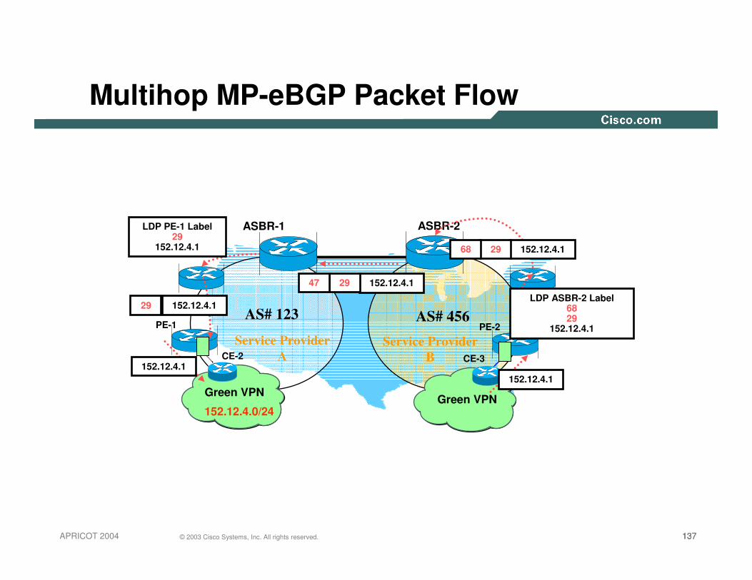
137137137© 2003 Cisco Systems, Inc. All rights reserved.APRICOT 2004
Multihop MP-eBGP Packet Flow
PE-1
ASBR-1 ASBR-2
AS# 123 AS# 456PE-2
Green VPN
CE-2
152.12.4.0/24
CE-3
Green VPN
152.12.4.1
LDP PE-1 Label 29
152.12.4.1
152.12.4.1
152.12.4.129
29 152.12.4.1LDP ASBR-2 Label
68 29
152.12.4.1
68
152.12.4.12947
Service Provider A
Service Provider B
138138138© 2003 Cisco Systems, Inc. All rights reserved.APRICOT 2004
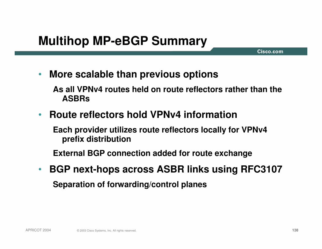
Multihop MP-eBGP Summary
• More scalable than previous optionsAs all VPNv4 routes held on route reflectors rather than the
ASBRs
• Route reflectors hold VPNv4 informationEach provider utilizes route reflectors locally for VPNv4
prefix distribution
External BGP connection added for route exchange
• BGP next-hops across ASBR links using RFC3107Separation of forwarding/control planes

139139139© 2003 Cisco Systems, Inc. All rights reserved.APRICOT 2004
ASBR/RR Router Protection/Filtering
• BGP sessions are authenticated via MD5Both the RFC3107 & MP-BGP sessions
Perhaps IPSec authentication in the data plane
• Maximum-prefix deployed on both BGP sessions
• ORF between RRs to filter on extended communities

140140140© 2003 Cisco Systems, Inc. All rights reserved.APRICOT 2004
Distribution of VPNv4 Prefix Information
���������
����!��"#����$%&'
����!��"#��� '(
RR5
RR6
RR7
RR8
RR1
RR2
RR3
RR4
��������)
Cluster-id 1 Cluster-id 2 Cluster-id 3 Cluster-id 4
MPMP--BGP BGP PeeringPeering
PE RouterPE Router

141141141© 2003 Cisco Systems, Inc. All rights reserved.APRICOT 2004
Route-reflector Topology
SF POP
LA POP
NY POP
RR
RR
RR
RRPE
RR
RR
WASH POP
RR
RR
PE
West
PE
PE
East

142142142© 2003 Cisco Systems, Inc. All rights reserved.APRICOT 2004
Route-reflectors with Reflector-groups
SF POP
LA POP
NY POP
RR
RR
RR
RR
RR
RR
WASH POP
RR
RR
����!��"#��� '(
Full Mesh
Cluster-id 1
Cluster-id 2
Cluster-id 3
Cluster-id 4

143143143© 2003 Cisco Systems, Inc. All rights reserved.APRICOT 2004
Key Features
• No constraints on addressing plans used by VPNs—a VPN customer may:
Use globally unique and routable/non-routable addresses,
Use private addresses (RFC1918)
• Security:
Basic security is comparable to that provided by FR/ATM-based VPNs without providing data encryption
VPN customer may still use IPSec-based mechanisms
e.g., CE- CE IPSec-based encryption

144144144© 2003 Cisco Systems, Inc. All rights reserved.APRICOT 2004
Key Features (Cont.)
• Quality of Service:Flexible and scaleable support for a CoS-based networks
• Scalability:Total capacity of the system isn’t bounded by the capacity of an individual component
Scale to virtually unlimited number of VPNs per VPN Service Provider and scale to thousands of sites per VPN

145145145© 2003 Cisco Systems, Inc. All rights reserved.APRICOT 2004
Key Features (Cont.)
• Connectivity to the Internet:VPN Service Provider may also provide connectivity to the Internet to its VPN customers
Common infrastructure is used for both VPN and the Internet connectivity services
• Simplifies operations and management for VPN Service Providers:
No need for VPN Service Providers to set up and manage a separate backbone or “virtual backbone” for each VPN

146146146© 2003 Cisco Systems, Inc. All rights reserved.APRICOT 2004
BGP/MPLS VPN—Summary
• Supports large scale VPN service
• Increases value add by the VPN Service Provider
• Decreases Service Provider cost of providing VPN services
• Mechanisms are general enough to enable VPN Service Provider to support a wide range of VPN customers

147147147© 2003 Cisco Systems, Inc. All rights reserved.APRICOT 2004
Deployment/Architecture Challenges
• As with all technologies there are challengesControl-plane Scale
Filtering & route distribution
Security
Multicast
QOS/End-to-end SLA’s
Integration of services e.g. Layer-2/Layer-3
Network Management
Traffic Engineering

148© 2003 Cisco Systems, Inc. All rights reserved.APRICOT 2004
MPLS Traffic Engineering
Azhar Sayeed

149149149© 2003 Cisco Systems, Inc. All rights reserved.APRICOT 2004
What Is MPLS Traffic Engineering?
• Process of routing data traffic in order to balance the traffic load on the various links, routers, and switches in the network
• Key in most networks where multiple parallel or alternate paths are available

150150150© 2003 Cisco Systems, Inc. All rights reserved.APRICOT 2004
Why Traffic Engineering?
• Congestion in the network due to changing traffic patternsElection news, online trading, major sports events
• Better utilization of available bandwidthRoute on the non-shortest path
• Route around failed links/nodesFast rerouting around failures, transparently to users
Like SONET APS (Automatic Protection Switching)
• Build New Services—Virtual leased line servicesVoIP Toll-Bypass applications, point-to-point bandwidth guarantees
• Capacity planningTE improves aggregate availability of the network

151151151© 2003 Cisco Systems, Inc. All rights reserved.APRICOT 2004
Background – Why Have MPLS-TE?
• IP networks route based only on destination (route)• ATM/FR networks switch based on both source and destination
(PVC, etc)• Some very large IP networks were built on ATM or FR to take
advantage of src/dst routing• Overlay networks inherently hinder scaling (see “The Fish
Problem”)• MPLS-TE lets you do src/dst routing while removing the major
scaling limitation of overlay networks• MPLS-TE has since evolved to do things other than bandwidth
optimization

152152152© 2003 Cisco Systems, Inc. All rights reserved.APRICOT 2004
R8
R2
R6
R3
R4
R7
R5
R1
IP (Mostly) Uses Destination-Based Least-Cost RoutingFlows from R8 and R1 Merge at R2 and Become IndistinguishableFrom R2, Traffic to R3, R4, R5 Use Upper Route
Alternate Path Under-Utilized
IP Routing and The Fish

153153153© 2003 Cisco Systems, Inc. All rights reserved.APRICOT 2004
Router F
The Problem with Shortest-Path
Changing to A->C->D->E won’t help
Router C Router D
Router G80Mb Traffic
80Mb Traffic
35Mb Drops!
35Mb Drops!Router A
Router B
NodeNode Next-HopNext-Hop CostCostBB 1010BB
FF 3030BB
CC 1010CCDD 2020CCEE 2020BB
GG 3030BB
OC-3OC-3
OC-3OC-3
DS3DS3
DS3DS3
DS3DS3OC-3OC-3
OC-3OC-3
• Some links are DS3, some are OC-3
• Router A has 40Mb of traffic for Route F, 40Mb of traffic for Router G
• Massive (44%) packet loss at Router B->Router E!
Router E

154154154© 2003 Cisco Systems, Inc. All rights reserved.APRICOT 2004
How MPLS TE Solves the Problem
• Router A sees all links
• Router A computes paths on properties other than just shortest cost
• No link oversubscribed!
NodeNode Next-HopNext-Hop CostCostBB 1010BB
F 30Tunnel 0
CC 1010CCDD 2020CCEE 2020BB
GG 3030Tunnel 1Tunnel 1
OC-3OC-3
OC-3OC-3
DS3DS3
DS3DS3
DS3DS3OC-3OC-3
OC-3OC-3
Router F
Router C Router D
Router G
Router A
Router B
Router E
40Mb40Mb
40Mb40Mb

155155155© 2003 Cisco Systems, Inc. All rights reserved.APRICOT 2004
A terminology slide – head, tail, LSP, etc
Upstream Downstream
Network X
TE tunnelR1 R2 R3
• Head-End is a router on which a TE tunnel is configured (R1)
• Tail-End is the router on which TE tunnel terminates (R3)
• Mid-point is a router thru which the TE tunnel passes (R2)
• LSP is the Label Switched Path taken by the TE tunnel, here R1-R2-R3
• Downstream router is a router closer to the tunnel tail
• Upstream router is farther from the tunnel tail (so R2 is upstream to R3’s downstream, R1 is upstream from R2’s downstream)

156156156© 2003 Cisco Systems, Inc. All rights reserved.APRICOT 2004
TE Fundamentals—“Building Blocks”
Path Calculation—Uses IGP Advertisements to Compute “Constrained” Paths
RSVP/TE Used to Distribute Labels, Provide CAC, Failure Notification, etc.
IGP (OSPF or ISIS) Used to Flood Bandwidth Information between Routers

157157157© 2003 Cisco Systems, Inc. All rights reserved.APRICOT 2004
Example
• PATH messages are sent with requested bandwidth• RESV messages are sent with label bindings for the TE tunnel• Tunnels can be explicitly routes• Admission control at each hop to see if the bandwidth
requirement can be met• Packets are mapped to the tunnel via
Static routedAutoroutePolicy route
• Packets follow the tunnel—LSP
TE Headend TE Tail EndPATH
PATHPATH
RESV
RESV
RESV

158158158© 2003 Cisco Systems, Inc. All rights reserved.APRICOT 2004
Traffic Engineering
158158158© 2003 Cisco Systems, Inc. All rights reserved.Presentation_ID

159159159© 2003 Cisco Systems, Inc. All rights reserved.APRICOT 2004
Theory
• Information Distribution
• Path Calculation
• Path Setup
• Routing Traffic Down A Tunnel

160160160© 2003 Cisco Systems, Inc. All rights reserved.APRICOT 2004
Information Distribution
• You need a link-state protocol as your IGP
IS-IS or OSPF
• Link-state requirement is only for MPLS-TE!
Not a requirement for VPNs, etc!
• Why do I need a link-state protocol?
To make sure info gets flooded
To build a picture of the entire network
• Information flooded includes Link, Bandwidth, Attributes, etc.

161161161© 2003 Cisco Systems, Inc. All rights reserved.APRICOT 2004
Information Distribution
• TE LSPs can (optionally) reserve bandwidth across the network
• Reserving bandwidth is one of the ways to find more optimal paths to a destination
• This is a control-plane reservation only
• Need to flood available bandwidth information across the network
• IGP extensions flood this information-OSPF uses Type 10 (area-local) Opaque LSAs
-ISIS uses new TLVs
-Some other information flooded, not important now

162162162© 2003 Cisco Systems, Inc. All rights reserved.APRICOT 2004
Path Calculation
• Once available bandwidth information is flooded, router may calculate a path from head to tail.
-Path may already be preconfigured on the router, will talk about that later
• TE Headend does a “Constrained SPF” (CSPF) calculation to find the best path
• CSPF is just like regular IGP SPF, except-Takes required bandwidth into account
-Looks for best path from a head to a single tail, not to all devices
• N tunnel tails, N CSPFs
• In practice, there has been zero impact from CSPF CPU utilization on even the largest networks

163163163© 2003 Cisco Systems, Inc. All rights reserved.APRICOT 2004
Path Setup
• Once the path is calculated, need to signal it across the network.
• Why? 2 reasons:1. Reserve any bandwidth, so that other LSPs can’t
overload the path
2. Establish an LSP for loop-free forwarding along an arbitrary path
– Like ATM VC/FR DLCI
– See “The Fish Problem”, later

164164164© 2003 Cisco Systems, Inc. All rights reserved.APRICOT 2004
Path Setup
• PATH messages = from head to tail (think “call setup”) carries LABEL_REQUEST
• RESV messages = from tail to head
(think “call ACK”) carries LABEL
• Other RSVP message types exist for LSP teardown and error signalling

165165165© 2003 Cisco Systems, Inc. All rights reserved.APRICOT 2004
Router F
Path Setup
• PATH message: “Can I have 40Mb along this path?”
• RESV message: “Yes, and here’s the label to use”
• LFIB is set up along each hop
Router B
Router C
Router E
Router D
Router G
Router A
= PATH Messages= RESV Messages
L=nullL=100
L=200
L=300

166166166© 2003 Cisco Systems, Inc. All rights reserved.APRICOT 2004
Path Setup
• Once RESV reaches headend, tunnel interface comes up
• Errors along the way are handled appropriately (tunnel does not come up, message gives point of failure and reason for failure)

167167167© 2003 Cisco Systems, Inc. All rights reserved.APRICOT 2004
Path Setup
Fundamental points here:• You can use MPLS-TE to forward traffic down a
path other than that determined by your IGP cost
• You can determine these arbitrary paths per tunnel headend

168168168© 2003 Cisco Systems, Inc. All rights reserved.APRICOT 2004
Routing Traffic Down A Tunnel
• Once RESV reaches headend, tunnel interface comes up
• How to get traffic down the tunnel?
1. Autoroute
2. Forwarding adjacency
3. Static routes
4. Policy routing

169169169© 2003 Cisco Systems, Inc. All rights reserved.APRICOT 2004
Autoroute
• Tunnel is treated as a directly connected link to the tail
• IGP adjacency is NOT run over the tunnel!Unlike an ATM/FR VC
• Autoroute limited to single area/level only

170170170© 2003 Cisco Systems, Inc. All rights reserved.APRICOT 2004
Autoroute
This Is the Physical Topology
Router FRouter H
Router B
Router C
Router E
Router D
Router G
Router A
Router I

171171171© 2003 Cisco Systems, Inc. All rights reserved.APRICOT 2004
Autoroute
• This is Router A’s logical topology
• By default, other routers don’t see the tunnel!
Tunnel1
Router FRouter H
Router B
Router C
Router E
Router D
Router G
Router A
Router I

172172172© 2003 Cisco Systems, Inc. All rights reserved.APRICOT 2004
Autoroute
• Router A’s routing table, built via auto-route
• Everything “behind” the tunnel is routed via the tunnel
Tunnel1
Router FRouter H
Router B
Router C
Router E
Router D
Router G
Router A
Router I
NodeNode Next-HopNext-Hop CostCostBB 1010BB
FF 3030BB
CC 1010CCDD 2020CCEE 2020BB
GG 3030Tunnel 1Tunnel 1HH 4040Tunnel 1Tunnel 1II 4040Tunnel 1Tunnel 1

173173173© 2003 Cisco Systems, Inc. All rights reserved.APRICOT 2004
Autoroute
• If there was a link from F to H, Router A would have 2 paths to H (A->G->H and A->B->E->F->H)
• Nothing else changes
Tunnel1
Router FRouter H
Router B
Router C
Router E
Router D
Router G
Router A
Router I
NodeNode Next-HopNext-Hop CostCostBB 1010BB
FF 3030BB
CC 1010CCDD 2020CCEE 2020BB
GG 3030Tunnel 1Tunnel 1HH 4040Tunnel 1 & BTunnel 1 & BII 4040Tunnel 1Tunnel 1

174174174© 2003 Cisco Systems, Inc. All rights reserved.APRICOT 2004
Forwarding Adjacency
• With autoroute, the LSP is not advertised into the IGP
• This is the right behavior if you’re adding TE to an IP network, but maybe not if you’re migrating from ATM/FR to TE
• Sometimes advertising the LSP into the IGP as a link is necessary to preserve the routing outside the ATM/FR cloud

175175175© 2003 Cisco Systems, Inc. All rights reserved.APRICOT 2004
ATM Model
• Cost of ATM links (blue) is unknown to routers• A sees two links in IGP—E->H and B->D• A can load-share between B and E
A I
E
BC
D
F GH

176176176© 2003 Cisco Systems, Inc. All rights reserved.APRICOT 2004
Before FA
• All links have cost of 10• A’s shortest path to I is A->B->C->D->I• A doesn’t see TE tunnels on {E,B}, alternate path never gets used!• Changing link costs is undesirable, can have strange
adverse effects
A I
E
B C D
F GH

177177177© 2003 Cisco Systems, Inc. All rights reserved.APRICOT 2004
F-A Advertises TE Tunnels in the IGP
• With forwarding-adjacency, A can see the TE tunnels as links
• A can then send traffic across both paths
• This is desirable in some topologies (looks just like ATM did, same methodologies can be applied)
A I
E
B C D
F GH

178178178© 2003 Cisco Systems, Inc. All rights reserved.APRICOT 2004
Unequal Cost Load Balancing
• IP routing has equal-cost load balancing, but not unequal cost*
• Unequal cost load balancing difficult to do while guaranteeing a loop-free topology
*EIGRP Has ‘Variance’, but That’s Not As Flexible

179179179© 2003 Cisco Systems, Inc. All rights reserved.APRICOT 2004
Unequal Cost Load Balancing
• Since MPLS doesn’t forward based on IP header, permanent routing loops don’t happen
• 16 hash buckets for next-hop, shared in roughproportion to configured tunnel bandwidth or load-share value

180180180© 2003 Cisco Systems, Inc. All rights reserved.APRICOT 2004
Unequal Cost: Example 1
Router A Router E
Router F
Router G
gsr1#show ip route 192.168.1.8Routing entry for 192.168.1.8/32
Known via "isis", distance 115, metric 83, type level-2Redistributing via isisLast update from 192.168.1.8 on Tunnel0, 00:00:21 agoRouting Descriptor Blocks:* 192.168.1.8, from 192.168.1.8, via Tunnel0
Route metric is 83, traffic share count is 2192.168.1.8, from 192.168.1.8, via Tunnel1
Route metric is 83, traffic share count is 1
����
����

181181181© 2003 Cisco Systems, Inc. All rights reserved.APRICOT 2004
Unequal Cost: Example 1
Note That the Load Distribution Is 11:5—Very Close to 2:1, but Not Quite!
gsr1#sh ip cef 192.168.1.8 internal………Load distribution: 0 1 0 1 0 1 0 1 0 1 0 0 0 0 0 0 (refcount 1)Hash OK Interface Address Packets Tags imposed1 Y Tunnel0 point2point 0 {23}2 Y Tunnel1 point2point 0 {34}
………
Router A 40MB
20MBRouter G
Router E
Router F

182182182© 2003 Cisco Systems, Inc. All rights reserved.APRICOT 2004
Practice
• Prerequisites (global config)
ip cef {distributed}
mpls traffic-eng tunnels

183183183© 2003 Cisco Systems, Inc. All rights reserved.APRICOT 2004
Practice
• Build a tunnel interface (headend)interface Tunnel0
tunnel mode mpls traffic-eng
ip unnumbered loopback0
tunnel destination <RID of tail>

184184184© 2003 Cisco Systems, Inc. All rights reserved.APRICOT 2004
Information Distribution
OSPFmpls traffic-eng tunnels
mpls traffic-eng router-id loopback0
mpls traffic-eng area <x>
ISISmpls traffic-eng tunnels
mpls traffic-eng router-id loopback0
mpls traffic-eng level-<x>
metric-style wide

185185185© 2003 Cisco Systems, Inc. All rights reserved.APRICOT 2004
Information Distribution
on each physical interface
mpls traffic-eng tunnels
(optional) ip rsvp bandwidth {x}

186186186© 2003 Cisco Systems, Inc. All rights reserved.APRICOT 2004
Path Calculation
EITHERint Tunnel0
tunnel mpls traffic-eng path-option <num> dynamic
ORint Tunnel0
tunnel mpls traffic-eng path-option <num> explicit name foo

187187187© 2003 Cisco Systems, Inc. All rights reserved.APRICOT 2004
Path Calculation
Global config:
ip explicit-path name foo
next-address 1.2.3.4 {loose}
next-address 1.2.3.8 {loose}
(etc)

188188188© 2003 Cisco Systems, Inc. All rights reserved.APRICOT 2004
Path Calculation
Global config:
ip explicit-path name foo
next-address 1.2.3.4 {loose}
next-address 1.2.3.8 {loose}
(etc)

189189189© 2003 Cisco Systems, Inc. All rights reserved.APRICOT 2004
Path Calculation
• Can have several path options, to be tried successively
tunnel mpls traffic-eng path-option 10 explicit name foo
tunnel mpls traffic-eng path-option 20 explicit name bar
tunnel mpls traffic-eng path-option 30 dynamic

190190190© 2003 Cisco Systems, Inc. All rights reserved.APRICOT 2004
Path Setup
• Nothing to configure to explicitly enable path setup
• mpls traffic-eng tunnels (from before) implicitly enables RSVP on the physical i/f

191191191© 2003 Cisco Systems, Inc. All rights reserved.APRICOT 2004
Routing Traffic Down A Tunnel
Autoroute:tunnel mpls traffic-eng autoroute announce
Forwarding adjacency:tunnel mpls traffic-eng forwarding-adjacency
thenisis metric <x> level-<y>
orip ospf cost <x>
on tunnel interface

192192192© 2003 Cisco Systems, Inc. All rights reserved.APRICOT 2004
Static routes
ip route <prefix> <mask> Tunnel0

193193193© 2003 Cisco Systems, Inc. All rights reserved.APRICOT 2004
Policy routing
access-list 101 permit tcp any any eq www
interface Serial0
ip policy route-map foo
route-map foo
match ip address 101
set interface Tunnel0

194194194© 2003 Cisco Systems, Inc. All rights reserved.APRICOT 2004
Summary Config
ip cef (distributed}
mpls traffic-eng tunnels
interface Tunnel0
tunnel mode mpls traffic-eng
ip unnumbered Loopback0
tunnel destination <RID of tail>
tunnel mpls traffic-eng autoroute announce
tunnel mpls traffic-eng path-option 10 dynamic

195195195© 2003 Cisco Systems, Inc. All rights reserved.APRICOT 2004
Summary Config
(in IGP)mpls traffic-eng tunnels
mpls traffic-eng router-id Loopback0
mpls traffic-eng area <x>
mpls traffic-eng level-<x>
metric-style wide
(physical interface)interface POS0/0
mpls traffic-eng tunnels
ip rsvp bandwidth <kbps>
OSPF
ISIS

196196196© 2003 Cisco Systems, Inc. All rights reserved.APRICOT 2004
Tips
• Some of the more useful ones:1. To advertise implicit-null from Tail-end
mpls traffic-eng signalling advertise implicit-null
2. To interpret explicit-null at PHP (hidden command)
mpls traffic-eng signalling interpret explicit-null
3. To automatically consider any new links as they come up
mpls traffic-eng reoptimize events link-up

197197197© 2003 Cisco Systems, Inc. All rights reserved.APRICOT 2004
Fast ReRoute
• Fundamental point from earlier: “you can use MPLS-TE to forward traffic down a path other than that determined by your IGP cost”
• FRR builds a path to be used in case of a failure in the network
• Minimize packet loss by avoiding transient routing loops

198198198© 2003 Cisco Systems, Inc. All rights reserved.APRICOT 2004
R1 R2
R9
R7 R8R6
R5R4R3
Reroutable LSP
NNHOP Back-up LSP
PLR
Merge Point
Protected LSP
NHOP backup LSP
Terminology

199199199© 2003 Cisco Systems, Inc. All rights reserved.APRICOT 2004
Applications of MPLS TE – MPLS Fast Re-Route
R8
R2
R6
R3R4
R7
R1 R5
R9
• Multiple hops can be by-passed; R2 swaps the label which R4 expects before pushing the label for R6
• R2 locally patches traffic onto the link with R6
• Multiple hops can be by-passed; R2 swaps the label which R4 expects before pushing the label for R6
• R2 locally patches traffic onto the link with R6
Mimic SONET APSRe-route in 50ms or Less

200200200© 2003 Cisco Systems, Inc. All rights reserved.APRICOT 2004
MPLS Fast Reroute local repair
• Link protection: the backup tunnel tail-head (MP) is one hop away from the PLR
• Node protection: the backup tunnel tail-end (MP) is two hops away from the PLR.
R1 R2 R5R4
R3
R1 R2
R9
R7 R8R6
R5R4R3
Fast ReRoute

201201201© 2003 Cisco Systems, Inc. All rights reserved.APRICOT 2004
IP failure recovery
For IP to recover from a failure, several things need to happen:
<100msLocal forwarding rewrite
~500ms-10secTOTAL:
- hundreds of msec with aggressive tuning (400ms for 500 pfx)
- sec (5-10) with defaults
Failure Propagation + SPF
usec-msecLink Failure Detection
TimeThing

202202202© 2003 Cisco Systems, Inc. All rights reserved.APRICOT 2004
FRR failure recovery
Since FRR is a local decision, no propagation needs to take place.
<100ms (often <50ms, <10ms with properly greased skateboard)
TOTAL:
<100msLocal forwarding rewrite
0Failure Propagation+SPF
usec-msecLink Failure Detection
TimeThing

203203203© 2003 Cisco Systems, Inc. All rights reserved.APRICOT 2004
Caveats
• As always, your mileage may vary. One slide does not do IP or FRR justice.
• Local failure recovery is always faster than distributed failure recovery
• What meets your needs? What makes more sense for your network? etc,..

204204204© 2003 Cisco Systems, Inc. All rights reserved.APRICOT 2004
FRR Procedures
1. pre-establish backup paths2. failure happens, protected traffic is switched
onto backup paths3. after local repair, tunnel headends are signalled
to recover if they want. No time pressure here, failure is being protected against
4. protection is in place for hopefully ~10-30+ seconds. during that time, data gets through.

205205205© 2003 Cisco Systems, Inc. All rights reserved.APRICOT 2004
Link Protection
• Primary Tunnel: A -> B -> D -> E• Backup Tunnel: B -> C -> D (Pre-provisioned)• Recovery = ~50ms
Router D
Router C
Router A Router B Router E
Router YRouter X
*Actual time varies—well below 50ms in lab tests, can also be higher

206206206© 2003 Cisco Systems, Inc. All rights reserved.APRICOT 2004
Node Protection
• Primary Tunnel: A -> B -> D -> E -> F• BackUp Tunnel: B -> C -> E (Pre-provisioned)• Recovery = ~100ms
Router E
Router C
Router A Router B Router F
Router YRouter X
Router D

207207207© 2003 Cisco Systems, Inc. All rights reserved.APRICOT 2004
Path Protection
• Primary Tunnel: A -> B -> D -> E -> F• BackUp Tunnel: A ->X -> C -> Y -> F (Pre-provisioned)• Recovery = >100ms
Router E
Router C
Router A Router B Router F
Router YRouter X
Router D

208208208© 2003 Cisco Systems, Inc. All rights reserved.APRICOT 2004
FRR Configuration
R1 R2 R5R4
R3
1) configure protection tunnel on R2
interface Tunnel0.. dest R4.. explicit-path R2-R3-R4.. NO autoroute!!!
3) headend requests protection
interface Tunnel0.. dest R4.. etc ...tunnel mpls traffic-eng fast-reroute
2) protect an interface
interface POS0/0mpls traffic-eng backup-path Tunnel0

209209209© 2003 Cisco Systems, Inc. All rights reserved.APRICOT 2004
FRR Tips
• Bandwidth protection vs. connectivity protection is the big one
• Do not want to reserve bandwidth on the protection tunnel, this is wasteful
• Either use TBPro (see later) or backup bandwidth on the protection tunnel (yellow tunnel in previous slide)
tunnel mpls traffic-eng backup-bw <kbps>
• Allows backup to be a little smart about where it protects primary tunnels
• Only really useful if protecting 1 interface with >1 tunnels
• Offline calculation can be much smarter, but there’s operational tradeoffs

210210210© 2003 Cisco Systems, Inc. All rights reserved.APRICOT 2004
Design and Scaling
• Designing with primary tunnels
• Designing with backup tunnels

211211211© 2003 Cisco Systems, Inc. All rights reserved.APRICOT 2004
Designing with primary tunnels
• Full mesh (strategic TE)
Mesh of TE tunnels between a level of routers
Typically P<->P, can be PE<->PE in smaller networks
O(N^2) LSPs
• As-needed (tactical TE)
Put a tunnel in place to work around temporary congestion due to unforseen shift in traffic demand
Need to keep an eye on your tunnels

212212212© 2003 Cisco Systems, Inc. All rights reserved.APRICOT 2004
Strategic TE (full mesh)
• Supported scalability numbers:
600 tunnel headends per node
10,000 midpoints per node
• Largest numbers deployed today:
100 routers full mesh = ~10,000 tunnels in the network
As many as 2,000-3,000 at certain midpoints
Plenty of room to grow!

213213213© 2003 Cisco Systems, Inc. All rights reserved.APRICOT 2004
Strategic
• Physical topology is:
Router A
Router B
Router D Router E
Router C

214214214© 2003 Cisco Systems, Inc. All rights reserved.APRICOT 2004
Strategic
• Logical topology is**Each link is actually 2 unidirectional tunnels
• Total of 20 tunnels in this networkRouter A
Router B
Router D Router E
Router C

215215215© 2003 Cisco Systems, Inc. All rights reserved.APRICOT 2004
Strategic
• Things to remember with full mesh
N routers, N*(N-1) tunnels
Routing protocols not run over TE tunnels—Unlike an ATM/FR full mesh!
Tunnels are unidirectional—This is a good thing
…Can have different bandwidth reservations in two different directions

216216216© 2003 Cisco Systems, Inc. All rights reserved.APRICOT 2004
Tactical
• All links are OC12
• A has consistent ±±±±700MB to send to C
• ~100MB constantly dropped!
Case Study: A Large US ISP
Router A
Router B
Router D Router E
Router C

217217217© 2003 Cisco Systems, Inc. All rights reserved.APRICOT 2004
Tactical
• Solution: Multiple tunnels, unequal cost load sharing!
• Tunnels with bandwidth in 3:1 (12:4) ratio = 525:175Mb
• 25% of traffic sent the long way
• 75% sent the short way
• No out-of-order packet issues— CEF’s normal per-flow hashing is used!
Router A
Router B
Router D Router E
Router C

218218218© 2003 Cisco Systems, Inc. All rights reserved.APRICOT 2004
Strategic vs. Tactical
• Both methods are in use today and have been for some years now
• Strategic means you always have a tunnel, and it means you have a lot of tunnels
Consistent mode of operation, lots of interfaces to manage
• Tactical means you only have tunnels when you have problems
…which means removing tunnels that are no longer necessary
• Which one you pick is up to you, both methods are valid

219219219© 2003 Cisco Systems, Inc. All rights reserved.APRICOT 2004
Designing with backup tunnels
• Connectivity protectionRouter calculates the path for its backup tunnelAssume that any found path can carry any link’s traffic during failureDon’t signal bandwidth for the backup tunnel!Use DiffServ to solve any contention due to congestion while FRR is in use
• Bandwidth protectionOffline tool calculates paths for protection LSPsAssurance that bandwidth is available during failureMore complex to maintain, may require additional network bandwidthAllows you to always meet SLAs during failure

220220220© 2003 Cisco Systems, Inc. All rights reserved.APRICOT 2004
Reasonable combinations
Bandwidth optimization (online or offline) + offline backup
1hop online + sporadic tactical
1hop offlinebandwidth protection
Bandwidth optimization (online or offline) + online backup
1hop online + sporadic tactical
1hop onlineconnectivity protection
Bandwidth optimization (online or offline)TE to work around congestion
IPnone
strategictacticalnoneprimary ->
|
v backup

221221221© 2003 Cisco Systems, Inc. All rights reserved.APRICOT 2004
1hop FRR
• Useful if you want to take advantage of FRR but don’t need primary bandwidth optimization
• All primary tunnels go between two directly connected nodes (tunnels are 1 hop long)
• Backup tunnel protects only that primary
• Currently in production in a few large IP (VPN, VoIP) networks
R1 R2 R5R4
R3

222222222© 2003 Cisco Systems, Inc. All rights reserved.APRICOT 2004
Bandwidth override on path option
• Can specify a bandwidth on a path-option that overrides the tunnel BW:
tunnel mpls traffic-eng bandwidth 1000tunnel mpls traffic-eng path-option 1 explicit name path1
tunnel mpls traffic-eng path-option 2 explicit name path2 bandwidth 500
tunnel mpls traffic-eng path-option 3 dynamic bandwidth 0

223223223© 2003 Cisco Systems, Inc. All rights reserved.APRICOT 2004
LSP Attribute Lists
• Control full set of LSP attributes per path, not per tunnel
• More complex, more powerful

224224224© 2003 Cisco Systems, Inc. All rights reserved.APRICOT 2004
AutoTunnel
• Obviates need to configure NHop and NNHopbackup tunnels
• Further enhancements on the radar (mesh groups)
mpls traffic-eng auto-tunnel backup
• No configuring backup or 1-hop primary tunnels!• Tradeoff between convenience and flexibility

225225225© 2003 Cisco Systems, Inc. All rights reserved.APRICOT 2004
Benefits of TE over Policy Routing
• Policy RoutingHop-by-hop decision making
No accounting of bandwidth
• Traffic EngineeringHead end based
Accounts for available link bandwidth
Admission control

226© 2003 Cisco Systems, Inc. All rights reserved.APRICOT 2004
TE Deployment Scenarios

227227227© 2003 Cisco Systems, Inc. All rights reserved.APRICOT 2004
Tactical TE Deployment
InternetService Provider
Backbone
Bulk of Traffic FlowEg. Internet Download
Oversubscribed Shortest Links
MPLS Traffic Engineering Tunnel Relieves Congestion Points
Requirement: Need to handle scattered congestion points in the NetworkSolution: Deploy MPLS TE on only those nodes that face congestionRequirement: Need to handle scattered congestion points in the NetworkSolution: Deploy MPLS TE on only those nodes that face congestion

228228228© 2003 Cisco Systems, Inc. All rights reserved.APRICOT 2004
Full Mesh TE Deployment
Service ProviderBackbone
Full Mesh of MPLS Traffic Engineering Tunnels
Partial Mesh of Physical Connections
Requirement: Need to increase “bandwidth inventory” across the networkSolution: Deploy MPLS TE with a full logical mesh over a partial physical mesh
and use Offline Capacity Planning Tool
Requirement: Need to increase “bandwidth inventory” across the networkSolution: Deploy MPLS TE with a full logical mesh over a partial physical mesh
and use Offline Capacity Planning Tool
VPN Site A VPN Site B

229229229© 2003 Cisco Systems, Inc. All rights reserved.APRICOT 2004
VPN Site BVPN Site A
1-Hop TE Deployment
Requirement: Need protection only—minimize packet lossLots of Bandwidth in the core
Solution: Deploy MPLS Fast Reroute for less than 50ms failover time with 1-HopPrimary TE Tunnels and Backup Tunnel for each
Requirement: Need protection only—minimize packet lossLots of Bandwidth in the core
Solution: Deploy MPLS Fast Reroute for less than 50ms failover time with 1-HopPrimary TE Tunnels and Backup Tunnel for each
Service ProviderBackbone
Primary 1-Hop TE TunnelBackup TunnelPhysical Links

230230230© 2003 Cisco Systems, Inc. All rights reserved.APRICOT 2004
VPN Site B
VPN Site A
Virtual Leased Line Deployment
Requirement: Need to create dedicated point-to-point circuits with bandwidth guarantees—Virtual Leased Line (VLL)
Solution: Deploy MPLS TE (or DS-TE) with QoS; Forward traffic from L3 VPN or L2 VPN into a TE Tunnel; Unlike ATM PVCs, use 1 TE Tunnel formultiple VPNs creating a scalable architecture
Requirement: Need to create dedicated point-to-point circuits with bandwidth guarantees—Virtual Leased Line (VLL)
Solution: Deploy MPLS TE (or DS-TE) with QoS; Forward traffic from L3 VPN or L2 VPN into a TE Tunnel; Unlike ATM PVCs, use 1 TE Tunnel formultiple VPNs creating a scalable architecture
Service ProviderBackbone
Tight QoS—Policing, Queuing Etc.
Traffic Engineered Tunnels with Fast Reroute Protection
Primary TunnelBackup Tunnel
Central Site

231231231© 2003 Cisco Systems, Inc. All rights reserved.APRICOT 2004
MPLS TE Summary
• Useful for re-routing traffic in congested environments
• Build innovative services like Virtual Leased line
• Build protection solutions using MPLS FRR

232232232© 2003 Cisco Systems, Inc. All rights reserved.APRICOT 2004
Management Considerations and MPLS OAM
Monique Morrow
232232232© 2003 Cisco Systems, Inc. All rights reserved.Presentation_ID

233233233© 2003 Cisco Systems, Inc. All rights reserved.APRICOT 2004
What is MPLS Operations And Management?
• The tools and techniques required to successfully deploy an MPLS network
Fault-managementConfiguration Accounting PerformanceSecurity

234234234© 2003 Cisco Systems, Inc. All rights reserved.APRICOT 2004
Customer Requirements
• Three categories of requirements from 1st tier PWE/MPLS Service Providers (and others).
�VC/LSP Path Verification and Tracing
�Built-in Protocol Operations
�Standard Management APIs/NMS Applications
MIBs, CLI, XML, etc…
�Documented in: draft-ietf-mpls-oam-requirements-01.txt
�Must be addressed before many providers will deploy PWE3 services.

235235235© 2003 Cisco Systems, Inc. All rights reserved.APRICOT 2004
Summary Customer Requirements
• Management: Enabling service deliveryFault managementService Management
• ILEC view of network management very different than ISPs
Fault detection, isolation (details coming up)• Customer visible OAM
OAM Emulation for ATM AAL5OAM cell generation for ATM over MPLS upon change of VC status (eg – label withdrawal)OAM Cell generation for LC_ATM

236236236© 2003 Cisco Systems, Inc. All rights reserved.APRICOT 2004
Fault Detection and Isolation
Control Plane Verification
• Consistency check
• Authentication
Data Plane Verification
• Ability to verify connectivity and trace
Paths from PE to PE – Global routing table as well as VPNs
Paths from CE to CE within a VPN
TE tunnels
Pseudo-wires

237237237© 2003 Cisco Systems, Inc. All rights reserved.APRICOT 2004
VC/LSP Connection Verification and Trace Requirements
• Automated detection and diagnosis of broken transport LSPs and VCs:
Point-to-point
Multipoint-to-point
Equal Cost Multi-Path (ECMP)
Using LSP ping/tunnel trace capability from both head-end and mid-points.
Data plane OAM packets must follow same path they are testing!

238238238© 2003 Cisco Systems, Inc. All rights reserved.APRICOT 2004
VC/LSP Connection Verification and Trace Requirements (cont)
• Automatic lightweight IP-like ping to test end-to-end path connectivity (e.g.: CE-CE).
• Operator configurable parameters/actions:
–Frequency of VCCV.
–MPLS Fast-Reroute
–Automated VCCV
• Verification of VPN integrity by providing a mechanism to detect LSP mis-merging.
• Documented in:
www.ietf.org/internet-drafts/draft-ietf-pwe3-vccv-01.txt

239239239© 2003 Cisco Systems, Inc. All rights reserved.APRICOT 2004
LSP Ping
• Similar to ICMP (IP) PingSequence NumberTimestampsSender Identification
• Full identification of FEC based the application• Variable length for MTU discovery• Support for tunnel/path tracing• Multiple-reply modes• Handles ECMP
• Reference
http://www.ietf.org/internet-drafts/draft-ietf-mpls-lsp-ping-03.txt

240240240© 2003 Cisco Systems, Inc. All rights reserved.APRICOT 2004
MPLS Ping: Operation
• Ping Mode: Connectivity check of an LSP
Test if a particular "FEC" ends at the right egress LSR
• Traceroute Mode: Hop by Hop fault localization
• Uses two messages
MPLS Echo Request
MPLS Echo Reply
• Packet need to follow data path

241241241© 2003 Cisco Systems, Inc. All rights reserved.APRICOT 2004
MPLS Ping Message Format
Message Type1 Echo Request2 Echo Reply
Reply ModeNo replyIPv4 UDP packet IPv4 UDP packet with
Router alertControl Plane
TLVs includeFEC to be checked
0 1 2 3
0 1 2 3 4 5 6 7 8 9 0 1 2 3 4 5 6 7 8 9 0 1 2 3 4 5 6 7 8 9 0 1
+-+-+-+-+-+-+-+-+-+-+-+-+-+-+-+-+-+-+-+-+-+-+-+-+-+-+-+-+-+-+-+-+
| Version Number | Must Be Zero |
+-+-+-+-+-+-+-+-+-+-+-+-+-+-+-+-+-+-+-+-+-+-+-+-+-+-+-+-+-+-+-+-+
| Message Type | Reply mode | Return Code | Return Subcode|
+-+-+-+-+-+-+-+-+-+-+-+-+-+-+-+-+-+-+-+-+-+-+-+-+-+-+-+-+-+-+-+-+
| Sender's Handle |
+-+-+-+-+-+-+-+-+-+-+-+-+-+-+-+-+-+-+-+-+-+-+-+-+-+-+-+-+-+-+-+-+
| Sequence Number |
+-+-+-+-+-+-+-+-+-+-+-+-+-+-+-+-+-+-+-+-+-+-+-+-+-+-+-+-+-+-+-+-+
| TimeStamp Sent (seconds) |
+-+-+-+-+-+-+-+-+-+-+-+-+-+-+-+-+-+-+-+-+-+-+-+-+-+-+-+-+-+-+-+-+
| TimeStamp Sent (microseconds) |
+-+-+-+-+-+-+-+-+-+-+-+-+-+-+-+-+-+-+-+-+-+-+-+-+-+-+-+-+-+-+-+-+
| TimeStamp Received (seconds) |
+-+-+-+-+-+-+-+-+-+-+-+-+-+-+-+-+-+-+-+-+-+-+-+-+-+-+-+-+-+-+-+-+
| TimeStamp Received (microseconds) |
+-+-+-+-+-+-+-+-+-+-+-+-+-+-+-+-+-+-+-+-+-+-+-+-+-+-+-+-+-+-+-+-+
| TLVs ... |
: :
: :
| |
+-+-+-+-+-+-+-+-+-+-+-+-+-+-+-+-+-+-+-+-+-+-+-+-+-+-+-+-+-+-+-+-+

242242242© 2003 Cisco Systems, Inc. All rights reserved.APRICOT 2004
MPLS Ping: Packet Flow
• Ping with label for FEC=192.169.10.0/24
• Label Switched at R2, R3
• R3 pops label off
• R4 processes packet
192.168.10.0/24
R4
R5
R3
R1 R2

243243243© 2003 Cisco Systems, Inc. All rights reserved.APRICOT 2004
Packet Flow Ping Mode:Egress node
• Check Packet integrity
• Check if FEC distribution protocol is associated with incoming interface
• Check if valid egress node for the FEC
• Send echo Reply according to value of Reply Mode
R4
R5
R3
R1 R2

244244244© 2003 Cisco Systems, Inc. All rights reserved.APRICOT 2004
MPLS Traceroute: Packet Flow
• MPLS Ping Packets are sent with TTL=1,2,3
• Label switched if TTL > 1
• Processed where TTL expires
192.168.10.0/24
R4
R5
R3
R1 R2

245245245© 2003 Cisco Systems, Inc. All rights reserved.APRICOT 2004
Packet Flow Trace Mode:Transit Node
• Reply processing same as Ping, then
• Check for Downstream Mapping TLV
Determine nexthop routers
• Add Downstream Mapping TLVs for each
Compute label stacks, address/label ranges
• Return received Label Stack if requested
R4
R5
R3
R1 R2

246246246© 2003 Cisco Systems, Inc. All rights reserved.APRICOT 2004
Packet Flow Trace Mode:Transit Node
• Reply processing same as Ping, then
• Check for Downstream Mapping TLV
Determine nexthop routers
• Add Downstream Mapping TLVs for each
Compute label stacks, address/label ranges
• Return received Label Stack if requested
R4
R5
R3
R1 R2

247247247© 2003 Cisco Systems, Inc. All rights reserved.APRICOT 2004
Trace Mode: TTL>1
• Copy one Downstream Mapping TLV from Echo Reply
• Pick one IP Address from address in DM TLV
• Send a new Echo Request with TTL+1
• Repeat (if appropriated) for each DM TLV
• Reply from Egress stops iteration

248248248© 2003 Cisco Systems, Inc. All rights reserved.APRICOT 2004
Motivation
• Scalability
• Locality of alerts
• Exchange Link Local Identifiers if your IGP can’t do it for you
• Test dormant paths

249249249© 2003 Cisco Systems, Inc. All rights reserved.APRICOT 2004
Self Test
• Instead of testing every path
• Test every segment
POP APOP B
CORE

250250250© 2003 Cisco Systems, Inc. All rights reserved.APRICOT 2004
Self Test
• Instead of testing every path
• Test every segment
UPSTREAM
DOWNSTREAM

251251251© 2003 Cisco Systems, Inc. All rights reserved.APRICOT 2004
Dormant Interfaces
• Interface labels programmed ahead of time
• E2E OAM tests only active paths
• If link D-E fails link D will begin using link C-D C gets no notification of this event
E
A
DB
C

252252252© 2003 Cisco Systems, Inc. All rights reserved.APRICOT 2004
Overview of Operation
Echo ReplyRespond (CP*)Evaluate (CP)
UpstreamLSR
Echo RequestSend (CP)Loop (DP)Test (DP)
Two messages, five actions:
Send
Loop Test
RespondEvaluateDownstream
LSRSelf Test
LSR
*Handled on linecardCP – Control PlaneDP – Data Plane

253253253© 2003 Cisco Systems, Inc. All rights reserved.APRICOT 2004
Loopback Label
• Semantics are simple
• Label applies to a particular interface
• Pop label
• Forward out advertised interface

254254254© 2003 Cisco Systems, Inc. All rights reserved.APRICOT 2004
Initiation details
UpstreamLSR
DownstreamLSR
Self TestLSR
• Pick an interface and label to be tested
• Pick addresses so that ECMP should forward to Downstream LSR
• Record Downstream LSR, outgoing interface and label stack
• Affix label, set TTL=2, affix loopback label

255255255© 2003 Cisco Systems, Inc. All rights reserved.APRICOT 2004
Echo Request
UpstreamLSR Send
Loop Test
DownstreamLSR
Self TestLSR
• Self Test LSR sends Echo Request
• Looped through dataplane of Upstream LSR
• TTL is not decremented
• Flows through dataplane of Self Test LST
• TTL-expired causes receipt at Downstream LSR
Receipt

256256256© 2003 Cisco Systems, Inc. All rights reserved.APRICOT 2004
Downstream LSR Response
UpstreamLSR Send
Loop Test
RespondDownstream
LSRSelf Test
LSR
• Format Echo Reply
• Include incoming interface & label stack
• Send

257257257© 2003 Cisco Systems, Inc. All rights reserved.APRICOT 2004
Self Test Evaluation
• Compare actual and expectedRouterInterfaceLabel stack
• On error notify network managementOther automated responses possible
UpstreamLSR
LSR E
RespondEvaluateDownstream
LSRSelf Test
LSR

258258258© 2003 Cisco Systems, Inc. All rights reserved.APRICOT 2004
Bidirectional Forwarding Detection
• Simple, fixed-field, hello protocol
• Nodes transmit BFD packets periodically over respective directions of a path
• If a node stops receiving BFD packets some component of the bidirectional path is assumed to have failed
• Several modes of operation

259259259© 2003 Cisco Systems, Inc. All rights reserved.APRICOT 2004
BFD Control Packet
0 1 2 3
0 1 2 3 4 5 6 7 8 9 0 1 2 3 4 5 6 7 8 9 0 1 2 3 4 5 6 7 8 9 0 1
+-+-+-+-+-+-+-+-+-+-+-+-+-+-+-+-+-+-+-+-+-+-+-+-+-+-+-+-+-+-+-+-+
|Vers | Diag |H|D|P|F| Rsvd | Detect Mult | Length |
+-+-+-+-+-+-+-+-+-+-+-+-+-+-+-+-+-+-+-+-+-+-+-+-+-+-+-+-+-+-+-+-+
| My Discriminator |
+-+-+-+-+-+-+-+-+-+-+-+-+-+-+-+-+-+-+-+-+-+-+-+-+-+-+-+-+-+-+-+-+
| Your Discriminator |
+-+-+-+-+-+-+-+-+-+-+-+-+-+-+-+-+-+-+-+-+-+-+-+-+-+-+-+-+-+-+-+-+
| Desired Min TX Interval |
+-+-+-+-+-+-+-+-+-+-+-+-+-+-+-+-+-+-+-+-+-+-+-+-+-+-+-+-+-+-+-+-+
| Required Min RX Interval |
+-+-+-+-+-+-+-+-+-+-+-+-+-+-+-+-+-+-+-+-+-+-+-+-+-+-+-+-+-+-+-+-+
| Required Min Echo RX Interval |
+-+-+-+-+-+-+-+-+-+-+-+-+-+-+-+-+-+-+-+-+-+-+-+-+-+-+-+-+-+-+-+-+

260260260© 2003 Cisco Systems, Inc. All rights reserved.APRICOT 2004
Variable detection intervals
• Each node estimates how quickly it can send and receive BFD packets
• Nodes exchange the follow parameters in every control packet
Desired Min TX IntervalRequired Min RX IntervalDetect Multiplier
• These estimates can be modified in real time in order to adapt to unusual situations

261261261© 2003 Cisco Systems, Inc. All rights reserved.APRICOT 2004
Determining Detection Time
TX – Transmission Interval
RX – Receive Interval
Note that TX(a->b) = RX(b->a)
TX(a->b) = max(Desired Min TX(a), Required Min RX(b))
TX(b->a) = max(Desired Min TX(a), Required Min RX(b))
Detection Time(b) = Detect Mult(a) x T(a->b)
TX is jittered by 25%

262262262© 2003 Cisco Systems, Inc. All rights reserved.APRICOT 2004
Diagnostics
0 -- No Diagnostic1 -- Control Detection Time Expired (RDI)2 -- Echo Function Failed (N/A to VCCV)3 -- Neighbor Signaled Session Down (FDI)4 -- Forwarding Plane Reset (Indicates local
equipment failure)5 -- Path Down (Alarm Suppression)6 -- Concatenated Path Down (used to propagate
access link alarms)7 -- Administratively Down

263263263© 2003 Cisco Systems, Inc. All rights reserved.APRICOT 2004
Virtual Circuit Connection Verification (VCCV)
• Multiple PSN Tunnel TypesMPLS, IPSEC, L2TP, GRE,…
• MotivationOne tunnel can serve many pseudo-wires.MPLS LSP ping is sufficient to monitor the PSN tunnel (PE-PE connectivity), but not VCs inside of tunnel.
CE1 CE2PE1 PE2
PSN TunnelPW1
PW2
Emulated Service
Pseudo Wire
Native Service Native Service

264264264© 2003 Cisco Systems, Inc. All rights reserved.APRICOT 2004
VCCV Overview
• Mechanism for connectivity verification of PW
• Features
Works over MPLS or IP networks
In-band CV via control word flag or out-of-band option by inserting router alert label between tunnel and PW labels
Works with BFD, ICMP Ping and/or LSP ping
• VCCV results may drive OAM/LMI injection on corresponding AC(s)
• http://www.ietf.org/internet-drafts/draft-ietf-pwe3-vccv-02.txt

265265265© 2003 Cisco Systems, Inc. All rights reserved.APRICOT 2004
In Band VCCV Format
Control word use is signaled in LDP - Standard form:0 1 2 30 1 2 3 4 5 6 7 8 9 0 1 2 3 4 5 6 7 8 9 0 1 2 3 4 5 6 7 8 9 0 1+-+-+-+-+-+-+-+-+-+-+-+-+-+-+-+-+-+-+-+-+-+-+-+-+-+-+-+-+-+-+-+-+|0 0 0 0| Flags |FRG| Length | Sequence Number |+-+-+-+-+-+-+-+-+-+-+-+-+-+-+-+-+-+-+-+-+-+-+-+-+-+-+-+-+-+-+-+-+
OAM uses a different 1st nibble0 1 2 3
0 1 2 3 4 5 6 7 8 9 0 1 2 3 4 5 6 7 8 9 0 1 2 3 4 5 6 7 8 9 0 1
+-+-+-+-+-+-+-+-+-+-+-+-+-+-+-+-+-+-+-+-+-+-+-+-+-+-+-+-+-+-+-+-+
|0 0 0 1| reserved | PPP DLL Protocol Number=IPvX |
+-+-+-+-+-+-+-+-+-+-+-+-+-+-+-+-+-+-+-+-+-+-+-+-+-+-+-+-+-+-+-+-+
| IP OAM Packet: Ping / BFD / LSP Ping |
| |
+-+-+-+-+-+-+-+-+-+-+-+-+-+-+-+-+-+-+-+-+-+-+-+-+-+-+-+-+-+-+-+-+

266266266© 2003 Cisco Systems, Inc. All rights reserved.APRICOT 2004
PWE3 OAM Example:Continuity Verification
Attachment VCLSP Tunnel
• BFD provides a lightweight means of regular periodic CV
BFD Packet over VCCV channel
Attachment VCs

267267267© 2003 Cisco Systems, Inc. All rights reserved.APRICOT 2004
SLA Monitoring / Verification
• The OAM CV function can be extended for SLA measurement
• Measure quantity of OAM packets at each end of PW
• Timestamps in Ping, LSP Ping

268268268© 2003 Cisco Systems, Inc. All rights reserved.APRICOT 2004
Example of OperationCV/Trace Using VCCV and LSP Ping
Attachment VC
VCCV PacketIs lostAttachment VC
NMS/mgr Triggers VCCV
NMS/mgr Triggers LSP ping trace when failure detected

269269269© 2003 Cisco Systems, Inc. All rights reserved.APRICOT 2004
MPLS Security Considerations
Monique Morrow
269269269© 2003 Cisco Systems, Inc. All rights reserved.Presentation_ID

270270270© 2003 Cisco Systems, Inc. All rights reserved.APRICOT 2004
Three Pillars of Security
securityA
rchi
tect
ure
/A
lgor
ithm
Impl
emen
tatio
n
Ope
ratio
nBreak one, and all security is gone!

271271271© 2003 Cisco Systems, Inc. All rights reserved.APRICOT 2004
What Kind of Threats?
• Threats from Outside the BackboneFrom VPN customersFrom the Internet
• Threats from Inside the BackboneSP misconfigurations (error or deliberate)Hacker “on the line” in the core
• Threats that are independent of MPLSCustomer network security
Reference model for best practice deployments

272272272© 2003 Cisco Systems, Inc. All rights reserved.APRICOT 2004
MPLS VPN ServicesEdge Network
Internet Services Edge Network
MPLS Core
CE
CE
Backbone InfrastructureCustomer Access
Threat Points of References
InternetPE
Internet
PE
PE

273273273© 2003 Cisco Systems, Inc. All rights reserved.APRICOT 2004
MPLS VPN ServicesEdge Network
Internet Services Edge Network
MPLS Core
CE
CE
Backbone InfrastructureCustomer Access
Outside Backbone
Defeating VPN Separation
VPN Spoofing
DoS Against BGP-VPNs or backbone
PE
PE

274274274© 2003 Cisco Systems, Inc. All rights reserved.APRICOT 2004
MPLS VPN ServicesEdge Network
Internet Services Edge Network
MPLS Core
CE
CE
Backbone InfrastructureCustomer Access
Inside the Backbone
MisconfigurationsIn Core
Sniffing in Core
Inside attack forms
PE
PE
VPNMismerge

275275275© 2003 Cisco Systems, Inc. All rights reserved.APRICOT 2004
MPLS VPN ServicesEdge Network
Internet Services Edge Network
MPLS Core
CE
CE
Backbone InfrastructureCustomer Access
Threats Independent of MPLS
Intrusions such as telnet, snmp,Routing protocol
PE
PE
Customer Network Security

276276276© 2003 Cisco Systems, Inc. All rights reserved.APRICOT 2004
Ways to Attack
• “Intrusion”: Get un-authorised accessTheory: Not possible (as shown before)
Practice: Depends on:
- Vendor implementation
- Correct config and management
• “Denial-of-Service”: Deny access of othersMuch more interesting…
No Trust?
Use IPsecbetween CEs!

277277277© 2003 Cisco Systems, Inc. All rights reserved.APRICOT 2004
DoS against MPLS
• DoS is about Resource Starvation, one of:- Bandwidth
- CPU
- Memory (buffers, routing tables, …)
- In MPLS, we have to examine:
- Rest is the same as in other networks
CE PE

278278278© 2003 Cisco Systems, Inc. All rights reserved.APRICOT 2004
Attacking a CE from MPLS (other VPN)
• Is the CE reachable from the MPLS side?-> only if this is an Internet CE, otherwise not!
(CE-PE addressing is part of VPN!)
• For Internet CEs: Same security rules apply as for any other access router.
MPLS hides VPN-CEs: Secure! Internet CEs: Same as in other networks

279279279© 2003 Cisco Systems, Inc. All rights reserved.APRICOT 2004
Attacking a CE-PE Line
• Also depends on reachability of CE or the VPN behind it
• Only an issue for Lines to Internet-CEs Same considerations as in normal networks
• If CE-PE line shared (VPN and Internet):DoS on Internet may influence VPN! Use CAR!
MPLS hides VPN-CEs: Secure! Internet CEs: Same as in other networks

280280280© 2003 Cisco Systems, Inc. All rights reserved.APRICOT 2004
Attacking a PE Router
Only visible: “your” interfaceand interfaces of Internet CEs
PEIP(PE; l0)
IP(P)
CE2IP(CE2) IP(PE; fa1) VRF CE2
CE1IP(CE1) IP(PE; fa0)
VRF CE1
VRF InternetAttack points

281281281© 2003 Cisco Systems, Inc. All rights reserved.APRICOT 2004
DoS Attacks to PE can come from:
• Other VPN, connected to same PE
• Internet, if PE carries Internet VRF
Possible Attacks:
• Resource starvation on PEToo many routing updates, too many SNMP requests, small servers, …
Has to be secured

282282282© 2003 Cisco Systems, Inc. All rights reserved.APRICOT 2004
Layer 2 Comparison Context
• VPNs delivered via Layer 2 point-to-point connections such as ATM, Frame Relay
• Address and routing separation in MPLS-VPN architecture is equivalent to Layer 2 models
• An MPLS-VPN network is resistant to DoS attacks as a Layer 2 network

283283283© 2003 Cisco Systems, Inc. All rights reserved.APRICOT 2004
Non-IP networks: Not 100% secure!!Example: Telephone Network
“I had access to most, if not all, of the switches in Las Vegas,” testified Mitnick, at a hearing of Nevada's Public Utilities Commission (PUC). “I had the same privileges as a Northern Telecom technician.”Source: http://online.securityfocus.com/news/497

284284284© 2003 Cisco Systems, Inc. All rights reserved.APRICOT 2004
Non-IP networks: Not 100% secure!!Example: ATM Switch
“a single 'land' packet sent to the telnet port (23) of either the inband or out-of-band interface will cause the device to stop responding to ip traffic. Over the course of 6-1/2 minutes, all CPU will be consumed and device reboots.”Source: Bugtraq, 15 June 2002: “Fore/Marconi ATM Switch 'land' vulnerability”, by [email protected];

285285285© 2003 Cisco Systems, Inc. All rights reserved.APRICOT 2004
Comparison with ATM / FR
ATM/FR MPLS
Address space separation yes yes
Routing separation yes yes
Resistance to attacks yes yes
Resistance to Label Spoofing
yes yes
Direct CE-CE Authentication (layer 3)
yes with IPsec

286286286© 2003 Cisco Systems, Inc. All rights reserved.APRICOT 2004
From RFC2547bis: Data Plane Protection
• Inter-AS should only be provisioned over secure, private peerings
• Specifically NOT: Internet Exchange Points (anyone could send labelled packets!! No filtering possible!!)
1. a backbone router does not accept labeled packets over a particular data link, unless it is known that that data link attaches only to trusted systems, or unless it is known that such packets will leave the backbone before the IP header or any labels lower in the stack will be inspected, and …

287287287© 2003 Cisco Systems, Inc. All rights reserved.APRICOT 2004
From RFC2547bis: Control Plane Protection
2. labeled VPN-IPv4 routes are not accepted from untrusted or unreliable routing peers,
• Accept routes with labels only from trusted peers
• Plus usual BGP filtering (see ISP Essentials*)

288288288© 2003 Cisco Systems, Inc. All rights reserved.APRICOT 2004
mbehring
Inter-AS: Case 10.a)VRF-VRF back-to-back
• Control plane: No signalling, no labels
• Data plane: IPv4 only, no labels accepted
• Security: as in 2547
• Customer must trust both SPs
Cust. Cust.AS 1 AS 2CE CE
PE ASBR PEASBR
IP dataLSP LSP

289289289© 2003 Cisco Systems, Inc. All rights reserved.APRICOT 2004
Security of Inter-AS 10.a)
• Static mappingSP1 does not “see” SP2’s network
And does not run routing with SP2, except within the VPNs.
���� Quite secure
• Potential issues: SP 1 can connect VPN connection wrongly(like in ATM/FR)

290290290© 2003 Cisco Systems, Inc. All rights reserved.APRICOT 2004
mbehring
Inter-AS: Case 10.b)ASBR exchange labelled VPNv4 routes
• Control plane: MP-BGP, labels
• Data plane: Packets with one label
• AS1 can insert traffic into any shared VPN of AS2
• Customer must trust both SPs
Cust. Cust.AS 1 AS 2CE CE
PE ASBR PEASBR
VPN label IP data
MP-BGP+labels
LSP LSP

291291291© 2003 Cisco Systems, Inc. All rights reserved.APRICOT 2004
Security of Inter-AS 10.b)
• ASBR1 does signalling with ASBR2MP-BGP: has to be secured, dampening etc
Otherwise no visibility of the other AS (ASBR1 – ASBR2 is the only interface between the SPs.)
• Potential Issues:SP1 can bring wrong CEs into any shared VPN
SP1 can send packets into any shared VPN (not into VPNsthat are not shared, since label is checked);
���� SP can make any shared VPN insecure
Watch layer-2 security!!(more later)

292292292© 2003 Cisco Systems, Inc. All rights reserved.APRICOT 2004
mbehring
Inter-AS: Case 10.c)ASBRs exchange PE loopbacks
• Control plane: ASBR: just PE loopback + labels; PE/RR: VPNv4 routes + labels
• Data plane: PE label + VPN label
• AS1 can insert traffic into VPNs in AS2
• Customer must trust both SPs
Cust. Cust.AS 1 AS 2CE CE
PE ASBR PEASBR
LSP
PE loopb+labels
VPN IP dataPE label
VPNv4 routes + labels

293293293© 2003 Cisco Systems, Inc. All rights reserved.APRICOT 2004
Security of Inter-AS 10.c)
• ASBR-ASBR signalling (BGP)RR-RR signalling (MP-BGP)
Much more “open” than 10.a) and 10.b)
LSPs between PEs, BGP between RR, ASBR
• Potential Issues:SP1 can bring a CE into any VPN on “shared” PEs
SP1 can intrude into any VPN on “shared” PEs
• Very open architectureprobably only applicable for ASes controlled by the same SP.
Watch layer-2 security!!(more later)

294294294© 2003 Cisco Systems, Inc. All rights reserved.APRICOT 2004
Inter-AS Summary and Recommendation
• Three different models for Inter-ASDifferent security properties
Most secure: Static VRF connections (10.a), but least scalable
• Basically the SPs have to trust each otherHard / impossible to secure against other SP in this model
• Okay if all ASes in control of one SP
• Current Recommendation: Use 10.a)

295295295© 2003 Cisco Systems, Inc. All rights reserved.APRICOT 2004
Inter-AS Recommendation
• Start with 10.a) (static VPN connections)Not many Inter-AS customers yet anyway ���� Easy start
• Maybe at some point (when many Inter-AS customers), move to 10.b) (ease of provisioning)
• 10.c) felt by most SPs as too open. Current recommendation: Only when both ASes under one common control

296296296© 2003 Cisco Systems, Inc. All rights reserved.APRICOT 2004
Carrier’s Carrier
• Same principles as in normal MPLS
• Customer trusts carrier who trusts carrier
Carrier’sCarrier
Cust. Cust.Carrier CarrierCE CE
PE
PE
PE
PEPE PE
IP
label
label
data
IP data
label IP data
label IP data
IP data

297297297© 2003 Cisco Systems, Inc. All rights reserved.APRICOT 2004
Carrier’s Carrier: The Interface
• Control Plane:PE1 assigns label to PE2
• Data Plane: PE1 only accepts packets with this label on this i/f
�PE1 controls data plane
�No label spoofing possible
Carrier’sCarrierCarrier
PE2 PE1
Watch layer-2 security!!(more later)

298298298© 2003 Cisco Systems, Inc. All rights reserved.APRICOT 2004
Carrier’s Carrier: Security
• Carrier is a VPN on core Carrier’s network
• Cannot spoof other VPN/carrier:PE verifies top label in data path
Top label determines egress PE
• Can mess up his own VPN!
• Basically like normal 2547

299299299© 2003 Cisco Systems, Inc. All rights reserved.APRICOT 2004
Carrier’s Carrier: Summary
• Can be secured wellCarrier has VPN on Carrier’s Carrier MPLS cloud
Carrier cannot intrude into other VPNs.
Carrier can mess up his own VPN (VPNs he offers to his customers)
• End customer must trust both SPs.

300300300© 2003 Cisco Systems, Inc. All rights reserved.APRICOT 2004
Watch out for Layer 2 Security!!
• 3rd party in same VLAN (e.g. IXP) can:insert spoofed packets into VPNs
(cannot be prevented today technically!!)
Do layer 2 attacks to do man-in-the-middle(could be mostly prevented, but is often not done)
ASBR ASBRIXP
Recommendation: Inter-AS and CsCconnections only on private peerings!!

301301301© 2003 Cisco Systems, Inc. All rights reserved.APRICOT 2004
VLAN Separation
• VLANs can be assumed to be separate, if…… The switch is not low end, very old or has bugs
… VTP (VLAN trunking protocol) is disabled on all ports (this is the default these days)
… Router ports are not trunk ports
… No ISL or 802.1q signalling to router port
All this can be done, so assuming correct config, VLANs are separate
But….

302302302© 2003 Cisco Systems, Inc. All rights reserved.APRICOT 2004
Within (!) a VLAN, Attacks are Easy!!
1. ARP spoofing (hacking tool hunt, arpspoof)
2. CAM overflow (hacking tool macof)
3. DoS against spanning tree
4. DoS storms (hacking tool exists)
Solutions:
• For 1 and 2: port security (hard to maintain…)Few SPs do this normally, so this attack is easy
• Disable Spanning Tree on router port, hard code Root Bridge

303303303© 2003 Cisco Systems, Inc. All rights reserved.APRICOT 2004
ARP Spoofing
IP aMAC A
IP bMAC B
IP cMAC C
• C is sending faked gratuitous ARP reply to A
• C sees traffic from IP a to IP b
C->A, ARP, b=C
C->A, ARP, b=CA->C, IP, a->b
A->C, IP, a->bC->B, IP, a->b
C->B, IP, a->b

304304304© 2003 Cisco Systems, Inc. All rights reserved.APRICOT 2004
Arpspoof in Action
C:\>test
C:\>arp -d 15.1.1.1
C:\>ping -n 1 15.1.1.1
Pinging 15.1.1.1 with 32 bytes of data:
Reply from 15.1.1.1: bytes=32 time<10ms TTL=255
C:\>arp -a
Interface: 15.1.1.26 on Interface 2Internet Address Physical Address Type15.1.1.1 00-04-4e-f2-d8-01 dynamic15.1.1.25 00-10-83-34-29-72 dynamic
C:\>_
C:\>test
C:\>arp -d 15.1.1.1
C:\>ping -n 1 15.1.1.1
Pinging 15.1.1.1 with 32 bytes of data:
Reply from 15.1.1.1: bytes=32 time<10ms TTL=255
C:\>arp -a
Interface: 15.1.1.26 on Interface 2Internet Address Physical Address Type15.1.1.1 00-04-4e-f2-d8-01 dynamic15.1.1.25 00-10-83-34-29-72 dynamic
C:\>arp -a
Interface: 15.1.1.26 on Interface 2Internet Address Physical Address Type15.1.1.1 00-10-83-34-29-72 dynamic15.1.1.25 00-10-83-34-29-72 dynamic
[root@hacker-lnx dsniff-2.3]# ./arpspoof 15.1.1.10:10:83:34:29:72 ff:ff:ff:ff:ff:ff 0806 42: arpreply 15.1.1.1 is-at 0:10:83:34:29:72

305305305© 2003 Cisco Systems, Inc. All rights reserved.APRICOT 2004
CAM Overflow 1/3
• theoretical attack until May 1999
• macof cracker tool since May 1999 (about 100 lines of perl)
• based on the limited size of CAM

306306306© 2003 Cisco Systems, Inc. All rights reserved.APRICOT 2004
CAM Overflow 2/3
MAC A MAC B
MAC C
Port 1Port 2
Port 3
MACMAC portportAA 11BB 22CC 33
X->?
X is on port 3
MACMAC portportXX 33BB 22CC 33
MACMAC portportXX 33YY 33CC 33
Y->?
Y is on port 3

307307307© 2003 Cisco Systems, Inc. All rights reserved.APRICOT 2004
CAM Overflow 3/3
MAC A MAC B
MAC C
Port 1Port 2
Port 3
MACMAC portportXX 33YY 33CC 33
A->B
A->B
A->B
B unknown…flood the frame
I see trafficto B !

308308308© 2003 Cisco Systems, Inc. All rights reserved.APRICOT 2004
Within (!) a VLAN, Attacks are Easy!!
1. ARP spoofing (hacking tool hunt, arpspoof)
2. CAM overflow (hacking tool macof)
3. DoS against spanning tree
4. DoS storms (hacking tool exists)
Solutions:
• For 1 and 2: port security (hard to maintain…)Few SPs do this normally, so this attack is easy
• For 3 and 4: Disable Spanning Tree on router port, hard code Root Bridge

309309309© 2003 Cisco Systems, Inc. All rights reserved.APRICOT 2004
Labelled packets on a VLAN
Data plane:
• Any label combination can be sent, by any station in the VLAN
• For CsC, top label (LSP) is checked by PE, VPN label cannot be checked, but affects only VPNsfrom the Carrier (not other carriers).
• For Inter-AS, neither LSP label nor VPN label is checked.

310310310© 2003 Cisco Systems, Inc. All rights reserved.APRICOT 2004
Recommendation for Advanced MPLS Networks
For Inter-AS and CsC (when labeledpackets are exchanged) do NOT use a shared VLAN.
Best: Dedicated connectionSecond best: Dedicated VLAN
RFC 2547bis states this explicitly!

311311311© 2003 Cisco Systems, Inc. All rights reserved.APRICOT 2004
Best Practice Security Overview (1)
• Secure devices (PE, P): They are trusted!
• Core (PE+P): Secure with ACLs on all interfaces
Ideal: deny ip any <core-networks>
• Static PE-CE routing where possible
• If routing: Use authentication (MD5)
• Separation of CE-PE links where possible(Internet / VPN)
• LDP authentication (MD5)
• VRF: Define maximum number of routes
Note: Overall security depends on weakest link!

312312312© 2003 Cisco Systems, Inc. All rights reserved.APRICOT 2004
In order of security preference:
1. Static: If no dynamic routing required(no security implications)
2. BGP: For redundancy and dynamic updates(many security features)
3. IGPs: If BGP not supported(limited security features)
PE-CE Routing Security

313313313© 2003 Cisco Systems, Inc. All rights reserved.APRICOT 2004
ACL and secure routing
Securing the MPLS Core
MPLS core
Internet
VPNVPN PE
CE
CE
CE
CE
CE CE
PE
PEPE
PE
P
P
P
VPN
VPN
VPN
BGP Route Reflector
BGP peering with MD5 authentic.
LDP with MD5

314314314© 2003 Cisco Systems, Inc. All rights reserved.APRICOT 2004
Neighbour Authentication (1)
• Prevents a router from receiving fraudulent updates from a routing neighbour
• Verifies updates it receives from a label distribution peer
• Support for BGP, ISIS, OSPF, EIGRP, RIPv2 and Label Distribution Protocol (LDP)

315315315© 2003 Cisco Systems, Inc. All rights reserved.APRICOT 2004
Neighbour Authentication (2)
• PE-CE: Selected PE-CE routing protocol plus LDP if CsC is enabled. If BGP+labels is being used on CsC, then authentication only on BGP session (no LDP required)
• PE-PE: BGP authentication for the secure exchange of VPNv4 routes
• PE to P and P to P: Authentication for the backbone routing protocol (IGP) plus LDP

316316316© 2003 Cisco Systems, Inc. All rights reserved.APRICOT 2004
Neighbour Authentication (3)
• Receiving router authenticates source of routing updates
• Two types: Plain text or message digest algorithm 5 (MD5)
• MD5 does not send key; creates message digest by using key and message as hash to MD5
• Resulting message digest exchanged among neighbours

317317317© 2003 Cisco Systems, Inc. All rights reserved.APRICOT 2004
Use IPsec if you need:
• Encryption of traffic
• Direct authentication of CEs
• Integrity of traffic
• Replay detection
• Or: If you don’t want to trust your ISP for traffic separation!
Maybe more important than
encryption?

318318318© 2003 Cisco Systems, Inc. All rights reserved.APRICOT 2004
End-to-End Security with IPsec
• Encryption: Data invisible on core
• Authentication: Only known CEs
• Integrity: Data not changed in transit
MPLS core
CE PEPE P PVPNVPN
CE
VPNPE labelIP dataIP sec IP dataIP secIP dataIP sec

319319319© 2003 Cisco Systems, Inc. All rights reserved.APRICOT 2004
Where to do IPsec
1. CE to CE
2. PE to PE
3. Mixture
MPLS core
CE PEPE P PVPNVPN
CE

320320320© 2003 Cisco Systems, Inc. All rights reserved.APRICOT 2004
Where to do IPsec
1. CE to CESP not involved (unless manages CEs)
MPLS network only sees IPsec traffic ���� Very secure
2. PE to PEDoes not prevent sniffing access line
� Not very secure for the customer
There are some specific applications for this (US ILECs)
3. MixturesNeed to trust SP
Mostly for access into VPN

321321321© 2003 Cisco Systems, Inc. All rights reserved.APRICOT 2004
MPLS doesn’t provide:
• Protection against mis-configurations in the core
• Protection against attacks from within the core
• Confidentiality, authentication, integrity, anti-replay ���� Use IPsec if required
• Customer network security

322322322© 2003 Cisco Systems, Inc. All rights reserved.APRICOT 2004
A Word About G-MPLS
Monique Morrow
322322322© 2003 Cisco Systems, Inc. All rights reserved.Presentation_ID

323323323© 2003 Cisco Systems, Inc. All rights reserved.APRICOT 2004
CoreDistributionCPE Aggregation
Legacy Data Reference Architecture Today Separate Layers
Optical
Optical
SDH/SONETATM
SDH/SONETATM
SDH/SONETSDH/SONET
channelised / LL
ATM/FR
Mod / TA PSTN
SDH
IP/MPLS
ATM/FR
PoP Services
Internet
PSTN
HFC
Optical Fibre Plant

324324324© 2003 Cisco Systems, Inc. All rights reserved.APRICOT 2004
What is Happening in Core ?
• Core bandwidth is increasing•Broadband based
•New Business services
• Slot count pressure
• 10 Gbps in production in larger PTT networks
• 40 Gbps requirement appearing
• 100 Gbps under discussion !
IP

325325325© 2003 Cisco Systems, Inc. All rights reserved.APRICOT 2004
IP Infrastructures Today
GE/POS over Dark Fiber POS over P-t-P DWDM
OpticalSDH
POS over SDH
Layer 2
L2 Core

326326326© 2003 Cisco Systems, Inc. All rights reserved.APRICOT 2004
E2e IP Infrastructures Today
DWDM
Dark Fibre Dark Fibre
Dark Fibre
SDH RPR or L2 service
SDH, RPR or L2 serviceSDH, RPR or L2 service

327327327© 2003 Cisco Systems, Inc. All rights reserved.APRICOT 2004
CoreDistributionCPE Aggregation
Data Reference ArchitectureFuture IP + Optical
OpticaldWDM dWDM
Ethernet / channelised / LL
ATM/FR
Mod / TA PSTN
802.11
Multi-Service optical transport
IP/MPLS
PoP Services
Internet
PSTN
HFC
GMPLS

328328328© 2003 Cisco Systems, Inc. All rights reserved.APRICOT 2004
Core Infrastructures Option 1 P-to-P DWDM / Dark Fibre / GE Switches
• Simplest model
• Very high BW connections
•STM-16c – STM-256c, RPR, GE, 10GE
•WAN PHY & LAN PHY Long Distance
• Static - Does it matter ?
• No layer 1 recovery
•L3 or FRR
• Cheap and efficient solution

329329329© 2003 Cisco Systems, Inc. All rights reserved.APRICOT 2004
Core Infrastructures Option 2Overlay without Signalling
OXC OXC
SDH / optical core
Control plane
• Router connected to optical network
• No signalling interaction
• Limited interaction between Router and optical layer
• Backup at either L1 or L3
• More dynamic / more cost
• Bandwidth capabilities determined by SDH / Optical layer

330330330© 2003 Cisco Systems, Inc. All rights reserved.APRICOT 2004
Core Infrastructures Option 3 Overlay with UNI
OXC OXC
SDH / optical coreUNI UNI
Control plane
• Optical UNI interface between Router and Optical Layer
• Overlay model
• Dynamic bandwidth / BW on demand
•Initiated from the edge
• Bandwidth capabilities determined by Optical Layer

331331331© 2003 Cisco Systems, Inc. All rights reserved.APRICOT 2004
Core Infrastructures Option 4 Peer Model – GMPLS / G.ASON / …
OXC OXC
Meshed optical core
GMPLS GMPLSGMPLS

332332332© 2003 Cisco Systems, Inc. All rights reserved.APRICOT 2004
Standards Bodies
Standards
MEF
Telcordia
Focus
Optical control plane requirements and signaling agreements for UNI and NNI
GMPLS based on extension to IP-based routing and signaling protocols specification to support optical control plane
Recommendations for ASON/ASTN covering architecture, technical concepts and functional components for control plane based optical paths setup. Leveraging OIF and IETF protocols
Developing Ethernet services support by OIF control plane
Proposing OSS strategy coupled with control plane to set up optical paths
Applicability to Cisco
OIF UNI 1.0
GMPLS as framework
Compliance required
Monitor
Monitor

333333333© 2003 Cisco Systems, Inc. All rights reserved.APRICOT 2004
Forwarding Plane
…. when MPLS started …
ControlPlane
MPLS DomainATM LSP
Packet LSP
IP Routing ProtocolsMPLS Domain - OSPF, ISIS, iBGP
Outside RIP2, BGP4
Label Distribution ProtocolsLDP, RSVP
Router
Router
Router
Router
Router
Router
Packet LSR Packet LSR
Packet LSRPacket LSR
ATM LSR
ATM LSR
ATM LSR
• General-purpose tunneling mechanismcarry IP and non-IP payloadsuses label switching to forward packets/cells through the networkcan operate over any data-link layer
• Separate Control Plane from Forwarding Plane
• Effort began 1996 ….. RFCs out 2001• RFC 3031 MPLS Architecture

334334334© 2003 Cisco Systems, Inc. All rights reserved.APRICOT 2004
Forwarding Plane
…. MPLS TE emerged …
ControlPlane
MPLS Domain
MPLS TEusing
RSVP TE
TE LSP
Router
Router
Router
Router
Router
Router
Packet LSR Packet LSR
Packet LSRPacket LSR
ATM LSR
ATM LSR
ATM LSR
• Constraint-based routing LSP tunnel established over set of links and nodesTunnel meets requested BW and/or policy constraints
• LSP tunnels are uni-directional ptpconnections
• Packets no longer need to follow shortest path

335335335© 2003 Cisco Systems, Inc. All rights reserved.APRICOT 2004
Forwarding Plane
MPλλλλS Domain
.… then came MPλλλλS …
ControlPlane
IP Routing ProtocolsOSPF, ISIS
Label Distribution ProtocolsLDP, RSVP TE
MPLS TERSVP TE
TE λλλλ LSP
TE λλλλ LSP
Router
Router
Router
Router
Router
Router
OXC
OXCOXC
OXC
OXC OXC
OXC
• Extend MPLS TE protocols to control optical cross-connect (OXC)
LSRs are like OXC LSPs are like optical connectionsReuse IP/MPLS protocols
• Advantagesfast provisioning of optical connectionsUnified IP/Optical Control Plane
• draft-awduche-mpls-te-optical-03.txt Q2 2001

336336336© 2003 Cisco Systems, Inc. All rights reserved.APRICOT 2004
Forwarding Plane
GMPLSDomainOTN
.… finally Generalized MPLS - GMPLS …
GMPLS ControlPlane IP Routing Protocols
With ExtensionsOSPF, ISIS
Label Distribution ProtocolsCR LDP, RSVP TE
MPLS TERSVP TE
• GMPLS control plane supports multiple switching and forwarding planes
• Introduces new functions to accommodate circuit-oriented optical network regimes
GMPLS = MPLS + MPλλλλS + N • where N is MPLS control of new switching planes• draft-ietf-ccamp-gmpls-architecture-07.txt
TE GMPLSPath
TE GMPLSPath
Router
Router
Router
Router
Router
Router
SONETSDH NE
SONETSDH NE
SONETSDH NE
SONETSDH NE
OXC
OXC OXC

337337337© 2003 Cisco Systems, Inc. All rights reserved.APRICOT 2004
Unified Control Plane
GMPLS
IP Routing ProtocolsWith Extensions
OSPF, ISIS
Label Distribution ProtocolsCR LDP, RSVP TE
MPLS TERSVP TE
Forwarding Plane
PSCDomain
GMPLS Domain
TDMDomain
OTN
LambdaDomain
FiberDomain
.… N-dimensional GMPLS …
TELSP
TELSP
SONETSDH NE
SONETSDH NE
OXC
OXC OXC
OXC
Router
Router
Router
Router
SONETSDH NE
SONETSDH NE
RouterRouter
RouterRouter λ Switch
λ Switch
λ Switch
λ Switch

338338338© 2003 Cisco Systems, Inc. All rights reserved.APRICOT 2004
Forwarding Plane
Unified Control Plane
GMPLS
IP Routing ProtocolsWith Extensions
OSPF, ISIS
Label Distribution ProtocolsCR LDP, RSVP TE
MPLS TERSVP TE
Multiple Sub-Domains in GMPLS Domain
PSCDomain
GMPLS Domain
TDMDomain
OTN
LambdaDomain
FiberDomain
OXC
OXC OXC
OXC
TDMDomain
OTN
LambdaDomain
FiberDomain
OXC
OXC OXC
OXC
TDMDomain
OTN
LambdaDomain
FiberDomain
OXC
OXC OXC
OXC

339339339© 2003 Cisco Systems, Inc. All rights reserved.APRICOT 2004
Multiple GMPLS Domains …
Forwarding Plane 1
Unified Control Plane 1GMPLS
OSPF, ISIS CR LDP, RSVP TE
MPLS TERSVP TE
PSCDomain
GMPLS Domain 1
TD
OTN
LD FD
TD
OTN
LD FD
TD
OTN
LD FD
Forwarding Plane 2
Unified Control Plane 2GMPLS
OSPF, ISIS CR LDP, RSVP TE
MPLS TERSVP TE
PSCDomain
GMPLS Domain 2
TD
OTN
LD FD
TD
OTN
LD FD
TD
OTN
LD FD
Forwarding Plane 3
Unified Control Plane 3GMPLS
OSPF, ISIS CR LDP, RSVP TE
MPLS TERSVP TE
PSCDomain
GMPLS Domain 3
TD
OTN
LD FD
TD
OTN
LD FD
TD
OTN
LD FD
? ?
?

340340340© 2003 Cisco Systems, Inc. All rights reserved.APRICOT 2004
Basic Concepts & Components
• Topology Discoveryrunning an IGP (OSPF or IS-IS) with extensions
• Route ComputationRoute computation done by NEs
Link state aggregation and lack of lightpathrelated information affects efficiency
• Neighbor DiscoveryLink Management Protocol like LMP/NDP run in distributed way
• Lightpath Setup Done by ingress NE using signaling protocol like RSVP-TE
CRLDP
RSVPTE
Signaling
LMP
OSPF
ISIS
Routing
RFC 3472 GMPLS Signaling CR-LDP Extensions
RFC 3473 GMPLS Signaling RSVP-TE Extensions

341341341© 2003 Cisco Systems, Inc. All rights reserved.APRICOT 2004
Forwarding Planes
• MPLS only supports LSRs which recognize packet/cell boundaries
• Support for devices making forwarding decision on other than packet/cell boundaries
• Forwarding plane switching decision based on interface type of LSR
Packet Switch Capable (PSC)
TDM Switch Capable (TSC)
Lambda Switch Capable (LSC)
Fiber Switch Capable (FSC)
RFC 3471 GMPLS Signaling Functional Description
���
��� ���
�� � � � �
�� ��
λλλλ
� �
��� ���
�� ����� ����
��� ���

342342342© 2003 Cisco Systems, Inc. All rights reserved.APRICOT 2004
Link Bundling & Unnumbered Links
• Issue
Neighboring LSRs connected by multiple parallel links
Each link is addressed at each end and advertised into routing database … lots of links !!!
• Solution
Aggregate multiple Components Links into a single Abstract Link
Use (Router ID, Interface #) for link identifiers
• Reduces number of links in routing database and amount of per-link configuration
• draft-kompella-mpls-bundle-05.txt
• draft-kompella-mpls-unnum-02.txt
LSR1 LSR2
1
2
3

343343343© 2003 Cisco Systems, Inc. All rights reserved.APRICOT 2004
Hierarchical LSPs
Unified Control PlaneGMPLS
IP Routing ProtocolsWith Extensions
OSPF, ISIS
Label Distribution ProtocolsCR LDP, RSVP TE
MPLS TERSVP TE
Forwarding Plane
PSCDomain
GMPLS Domain
TSCDomain
OTN
LSCDomain
FiberDomain
TELSP
TELSPSONET
SDH NE
SONETSDH NE
OXC
OXC OXC
OXC
Router
Router
Router
Router
SONETSDH NE
SONETSDH NE
RouterRouter
RouterRouter λ Switch
λ Switch
λ Switch
λ Switch
An LSP must start and end on the LSRs of the
same type.
FA-LSC LSPFiber
FA-TDM LSPLambda
FA-PCS LSPTDMLSP Packet
Nested LSPs

344344344© 2003 Cisco Systems, Inc. All rights reserved.APRICOT 2004
LSP Hierarchy
• Enables aggregation of GMPLS LSP tunnels• Accomplished by
Inter-LSR LSP tunnel (FA-LSP) link is createdIngress LSR injects link (FA-LSP) into IGP databaseOther routers use the link in path calculation/setupOther LSP tunnels are nested inside FA-LSP
• AdvantagesFewer high-order labels (e.g.lambdas) consumedNested LSPs can be of non-discrete bandwidthFA-LSP can “hide” topology
• draft-ietf-mpls-lsp-hierarchy-08.txt
FA-LSP…Forwarding Adjacency LSP
FA-LSC LSPFiber
FA-TDM LSPLambda
FA-PCS LSPTDMLSP Packet
Nested LSPs

345345345© 2003 Cisco Systems, Inc. All rights reserved.APRICOT 2004
LMP & Link Management
• LMP FunctionalityMost LMP messages sent out-of-band through CCIn-band messages sent for Component Link VerificationOnce allocated, Component Link is not assumed to be opaquePort ID mappingOne CC per one or more Component Link BundlesFault isolationEnd-system and service discovery (UNI related)
• Flooding Adjacencies are maintained over CC (via control network)
• Forwarding Adjacencies (FA) are maintained over Component Links and announced as links into the IGP
• draft-ietf-mpls-lmp-02.txt• draft-ietf-ccamp-lmp-10.txt • draft-ietf-ccamp-lmp-wdm-02.txt
...
In-bandLink Verification Messages
Component links
IP basedControl Network
... ...
Control Channel Control Channel
FA

346346346© 2003 Cisco Systems, Inc. All rights reserved.APRICOT 2004
GMPLS Signaling
• Extended label semantics for Fiber, Waveband, Lambda, TDM and PSC LSP setup• Extend RSVP-TE/CR-LDP for opaquely carrying new label objects over explicit path• Suggested Label - conveyed by upstream LSR to downstream LSR to speed up
configuration (on upstream)• Label Set - limits choice of labels that downstream LSR can choose from
If no wavelength conversion available then same lambdas must be used ete
• Bidirectional LSP setup
draft-ietf-mpls-generalized-signaling-09.txt
GMPLS Domain
PSCDomain
TDMDomain
OTN
LambdaDomain
FiberDomain
TELSP
TELSP

347347347© 2003 Cisco Systems, Inc. All rights reserved.APRICOT 2004
GMPLS Routing Extensions
• Extensions needed to deal with the polymorphic nature of GMPLS linkslinks that are not capable of forwarding packets nor can they support router adjacencies
links that are aggregates of many component links (e.g. link bundles)
links that are FAs between non-adjacent routers
• Define new sub-TLVs forOSPF Link TLV
IS-IS Reachability TLV
• Flooded over bi-directional control channels (CC) connecting GMPLS nodesCC may not necessarily follow topology of data bearing (component) links
• draft-ietf-ccamp-gmpls-routing-09.txt
• draft-ietf-ccamp-ospf-gmpls-extensions-12.txt
• draft-ietf-isis-gmpls-extensions-19.txt
• draft-ietf-ccamp-rsvp-te-exclude-route-00.txt

348348348© 2003 Cisco Systems, Inc. All rights reserved.APRICOT 2004
GMPLS Routing sub-TLVs
• Link Mux Capabilitydefines the receiving nodes ability to demultiplex data based on packets, TDM timeslots, lambdas or fiber
• Link Descriptorlink encoding type and bandwidth granularity
• Shared Risk Link Group (SRLG)physical fiber diversity - e.g. two fibers with same SRLG are in the same conduit
• Link Protection Type

349349349© 2003 Cisco Systems, Inc. All rights reserved.APRICOT 2004
GMPLS Overlay Routing Model
• UNI interactions - GMPLS signaling, LMP
• OTN interactions - GMPLS signaling, routing and LMP
• draft-ietf-ccamp-gmpls-overlay-02.txt
(RSVP Support for Overlay Model)
LSR OXC OXC OXC
UNI UNI
LMP LMP LMP LMP
Signaling Signaling
Signaling/Routing
LSR
LSP
OTN

350350350© 2003 Cisco Systems, Inc. All rights reserved.APRICOT 2004
GMPLS Peer Routing Model
• OTN interactions - GMPLS signaling, routing and LMP
• GMPLS protocol machinery can support overlay or peer routing models
• RFC 3473 GMPLS Signaling RSVP-TE Extensions
LSR OXC OXC OXC
LMP LMP LMP LMP
LSR
LSP
Signaling/Routing

351351351© 2003 Cisco Systems, Inc. All rights reserved.APRICOT 2004
Protection & Restoration
Many different Restoration & Protection Schemes (Co) exist todayMany different Restoration & Protection Schemes (Co) exist today ! !
draft-ietf-ccamp-gmpls-recovery-terminology-02.txt
SDH
OpticalProtection
IP
MPLS TE FRR
ProtectionProtectionStatic
Dynamic
Protection TypeProtection TypeNode ProtectionLink ProtectionProtection ModeProtection Mode
L1 OnlyL3 Only
L1 / L3 IndependentL1 / L3 Coordinated (Hold Off Timer)
L1 & L3 Interworking

352352352© 2003 Cisco Systems, Inc. All rights reserved.APRICOT 2004
GMPLS Protection / RestorationBased on MPLS TE FRR
• FRR mechanism to minimize packet loss during Link / Node Failure
• Pre-provisioned protection tunnels carry traffic when protected resource goes down
• MPLS-TE to signal FRR protection tunnels
MPLS TE traffic doesn’t have to follow IGP shortest path
• Can protect MPLS or IP traffic !
R1 R2 R5R4
R3
Link Protection
R1 R2
R9
R7 R8R6
R5R4R3
Node Protection

353353353© 2003 Cisco Systems, Inc. All rights reserved.APRICOT 2004
GMPLS Based Recovery
• LSP Protectionfull LSP signaling (cross-connection) before failure occurrence
• Pre-Planned Rerouting (with shared rerouting as particular case)Pre-signaling before failure – LSP activation after failure – allows for low priority
• LSP Dynamic Rerouting (aka restoration)full LSP signaling after failure occurrence
Terminology
Analysis
FunctionalSpecification
GMPLS RSVP-TESpecification
March 02
April 02
July 02
Aug 02
draft-ietf-ccamp-gmpls-recovery-terminology-02.txt
draft-ietf-ccamp-gmpls-recovery-analysis-02.txt
draft-ietf-ccamp-gmpls-recovery-functional-01.txt
draft-ietf-ccamp-gmpls-recovery-e2e-signaling-02.txt

354354354© 2003 Cisco Systems, Inc. All rights reserved.APRICOT 2004
GMPLS MIBs
• Based on MPLS MIBs - Revision 3 now readyhttp://www.olddog.co.uk/download
• Open issuesExpand conformance statements for configuration/monitoring tunnel resources in GMPLS systems like SONET/SDH or G.709
Extend performance tables for technology specific GMPLS LSPs
Consider way to expose
Tunnel heads
Tunnel tail
Tunnel transfer entries
Support for IF_ID control and error reporting
LSR or interface config for Hellos and Restart
• draft-ccamp-ietf-gmpls-tc-mib-01.txt
• draft-ccamp-ietf-gmpls-lsr-mib-01.txt
• draft-ccamp-ietf-gmpls-te-mib-01.txt

355355355© 2003 Cisco Systems, Inc. All rights reserved.APRICOT 2004
ITU-T SG 15 Communications to IETF CCAMPQestion14 – Optical Control Plane
• Recommendations G.7715.1 and living lists for G.7714.1 and G.7713 ftp://sg15opticalt:[email protected]/tsg15opticaltransport/COMMUNICATIONS/index.html
http://www.ietf.org/iesg/liaison.html
G.disc_arch G.frame
G.7714 G.7716 G.7713 G.7715 G.7712
G.7714.1 G.7713.1
G.7713.2
G.7713.3
DiscoveryArchitecture
ASONManagementFramework
Auto DiscoveryBased on EquipmentRec. G.783
Control PlaneInitialization& Recovery
Signalling -Distributed call &Connection Mgmt. Routing
DCN/SCN
G.7715.1
ITU-T SG 15, Question 14 - ASON Control & Management Recommendations
ProtocolNeutralRequirements(detailed)
ProtocolSpecifications
References CR LDP – RFC 3212
Discovery Mechanisms•ECC Interoperability References RFC 3474

356356356© 2003 Cisco Systems, Inc. All rights reserved.APRICOT 2004
GMPLS Extensions for ASON
• Extend GMPLS Signaling (RFC 3471 / RFC 3475)Must meet FULL functional requirements of ASON architecture in GMPLS
provide call & connection mgmt (G.7713)Must be BACKWARD COMPATIBLE with current GMPLS RFCs
• ASON architecture includesAutomated control plane supporting both call & connection mgmt (G.8080)Control plane applicable to different transport technologies (eg. SDH/SONET, OTN) & networking environments (eg. Inter-Carrier, Intra-Carrier)Refined reference point terminology (UNI, E-NNI, I-NNI)
• draft-ietf-ccamp-gmpls-ason-reqts-04.txt

357357357© 2003 Cisco Systems, Inc. All rights reserved.APRICOT 2004
GMPLS Extensions for ASONReference Point Terminology - UNI, ENNI, INNI
• ASON Reference Points Between administrative domain & user aka. User-network-interface (UNI)Between administrative domains aka. External-network-interface (E-NNI)Between areas of the same administrative domain & between controllers within areas aka. Internal-network-network-interface (I-NNI)
• Definition of GMPLS (RFC3473) compliant UNI• GMPLS-OVERLAY & GMPLS-VPN
Forwarding Plane 1
Unified Control Plane 1GMPLS
OSPF, ISIS CR LDP, RSVP TE
MPLS TERSVP TE
PSCDomain
GMPLS Domain 1
TD
OTN
LD FD
TD
OTN
LD FD
TD
OTN
LD FD
Forwarding Plane 2
Unified Control Plane 2GMPLS
OSPF, ISIS CR LDP, RSVP TE
MPLS TERSVP TE
PSCDomain
GMPLS Domain 2
TD
OTN
LD FD
TD
OTN
LD FD
TD
OTN
LD FD
UNI
UNI
ENNI
INNI
INNI INNI
INNI
Administrative Domain 1 - eg. SP1
Administrative Domain 2 - eg. SP2
INNI
INNI
• Soft permanent connection capability
• Call & connection separation, Call segments
• Extended restart capabilities during control plane failures
• Extended label association
• Crankback capability
• Additional error cases

358358358© 2003 Cisco Systems, Inc. All rights reserved.APRICOT 2004
GMPLS Extensions for ASONE2E Signaling over GMPLS and Non-GMPLS Domains
• e2e signalling regardless of administrative boundaries & protocols within the network
Includes both GMPLS control domains & non-GMPLS control domains
• ASON support within a GMPLS control domain & between GMPLS control domains
• Backward compatibility with GMPLS signaling extensions for ASON
Regardless if transit nodes speak GMPLS or not
ENNI
Forwarding Plane 2
PSCDomain
GMPLS Domain 2
TD
OTN
LD FD TD
OTN
LD FD
UNI
INNI TD
OTN
LD FD INNI
INNI
Administrative GMPLS Domain 2 - eg. SP2
• No restricted use of other protocols within the control domain
Forwarding Plane 1
PSCDomain
GMPLS Domain 1
TD
OTN
LD FD TD
OTN
LD FD
UNI
Administrative GMPLSDomain 1 - eg. SP1
INNI
INNI
TD
OTN
LD FD
Forwarding Plane
PSCDomain
TD
OTN
LD FD TD
OTN
LD FD
UNI
INNI TD
OTN
LD FD INNI
INNI
Administrative Non-GMPLSDomain - eg. SP3
ENNI

359359359© 2003 Cisco Systems, Inc. All rights reserved.APRICOT 2004
G.7713.2 / RFC3474 – RFC3473 Interworking
• RFCs 3473 and 3474 interworking explained indraft-ong-ccamp-3473-3474-iw-00.txt
Specifics are in the draftMore details and clarifications to be added
• RFC 3474 Key ConceptsOverlay or multiple domain model
Client interface (overlay)ENNI (between domains)
Client address space (TNA)Separate address space and format
Call-ID and related informationCarried transparently across intermediate nodes
Multi-session RSVPe2e connection stitched together from multiple tunnels
3473 domain Other domain

360360360© 2003 Cisco Systems, Inc. All rights reserved.APRICOT 2004
GMPLS RSVP TE Signaling in Support of ASON
• Backward/Forward compatible with GMPLS RFCs (RFC 3471/73)• Independence between UNI and E-NNI (agnosticism)• Interworking (at UNI and/or E-NNI) must be impact free on GMPLS RFCs• Intra-Domain and Inter-Domain Signaling• Only define new object and procedures when strictly needed (max re-use principle)
YesNoBackward Capability
OngoingNoCrankback Signaling
YesLimitedRestart (CP failures)
YesNoCall Segments
YesNoMultiple Connections per Call (add/remove)
YesYes (limited to single hop sessions)
Call w/ (single) Connection Setup
YesNoCall w/o Connection Setup
YesNoE2e Capability Negotiation
Yes (RFC 3473)Yes (SPC Label)Soft Permanent Connection
ProposalInfo RFC 3474/76Requirements
draft-dimitri-ccamp-gmpls-rsvp-te-ason-01.txt

361361361© 2003 Cisco Systems, Inc. All rights reserved.APRICOT 2004
ASON Routing Requirements
• Requirements to support ASON routing• Contains what’s missing in a “GMPLS ASON Routing
Requirements” document• Rules (same as for ASON signaling requirements)
No requirement that is not an ASON routing requirement (as decided by SG 15/Q12 and SG 15/Q14) will be considered in this document
• Functional RequirementsSupport of multiple hierarchical levelsSupport of multiple data plane layersSupport of architectural evolution
Levels, aggregation, segmentation
draft-alanqar-ccamp-gmpls-ason-routing-reqts-00.txt

362362362© 2003 Cisco Systems, Inc. All rights reserved.APRICOT 2004
Inter-Region / Inter-AS MPLS TE
• One common method for different “Regions”• Requirements defined by TEWG
Inter-AS draft-ietf-tewg-interas-mpls-te-req-01.txtInter-area draft-boyle-tewg-interarea-reqts-00.txt
• Each Region may either nest or stitch the Inter-Region TE LSP into a “different” Intra-Region TE LSP to carry the ete Multi-Region TE LSP
RSVP-TE signaling based on LSP Hierarchy (for both nested and stitching)Nesting of multiple inter-region LSPs into intra-region LSP
Control & forwarding plane scalability
• draft-ayyangar-inter-region-te-01.txtMultiple LSP pieces nested or stitched togetherPer region control
• draft-vasseur-inter-as-te-01.txtContiguous LSP eteHead end control

363363363© 2003 Cisco Systems, Inc. All rights reserved.APRICOT 2004
Inter-AS MPLS TE
• draft-vasseur-inter-AS-TE-01.txt• Defines signaling and routing mechanisms to make possible
the creation of paths that span multiple IGP areas, multiple ASs, and multiple providers, including techniques for crankback ….
• Draft defines two cenarios for signaling and routing of TE LSP spanning multiple ASs
Per AS path computationDistributed path computation between PSCs (ASBR)
• Can be used in combination with Hierarchical LSPs, crankback, …
• draft-vasseur-mpls-loose-path-reopt-01.txt proposes a set of mechanisms allowing a Head-end to exert a strict control on the TE LSP reoptimizing process and draft-ietf-mpls-nodeid-subobject-00.txt to support MPLS TE Fast Reroute

364364364© 2003 Cisco Systems, Inc. All rights reserved.APRICOT 2004
Two Scenarios
Scenario 1 - Per-AS TE LSP Path Computation
• No impact on RSVP/IGP scalability
• Semi-dynamic
• Small set of protocol extensions required
• No optimal e2e path
• Diverse path computation not always possible (path protection, load balancing)
• Call set up failure
• Support of e2e reoptimization(timer/event driven)
• Support of FRR Bypass for ASBR protection
Scenario 2 - Distributed Path Computation Server
• No impact on RSVP/IGP scalability
• Dynamic
• Implementation more complex
• Optimal e2e path
• Diverse path computation always possible (Path protection, load balancing)
• No call set up failure (not more than with single area/AS)
• Support of e2e reoptimization
• Support of FRR Bypass for ASBR protection
• TE LSP local protection recommended
Scenario 1 and 2 are both compliant with set of requirements defined in draft-ietf-tewg-interas-mpls-te-req-00.txt

365365365© 2003 Cisco Systems, Inc. All rights reserved.APRICOT 2004
Working Group Drafts
• WG last call soonGMPLS UNI
RSVP Support for Overlay Model
draft-ietf-ccamp-gmpls-overlay-02.txt
GMPLS Signaling Extensions for G.709 OTN Control
draft-ietf-ccamp-gmpls-g709-04.txt
• New revisions soonExclude Routers – Extensions to RSVP-TE
draft-ietf-ccamp-rsvp-te-exclude-route-00.txt
• Further discussionsASON requirements (draft-ietf-ccamp-gmpls-ason-reqts-04.txt)
Protection and Recovery drafts
GMPLS MIBs

366366366© 2003 Cisco Systems, Inc. All rights reserved.APRICOT 2004
Interaction with other WGs
• TEWGMulti-area AS requirementsdraft-ietf-tewg-interas-mpls-te-req
• MPLSPtmp LSPs - requirements and solutions include all switching typesdraft-yasukawa-mpls-p2mp-requirements)
• OSPF / IS-ISGMPLS extensions completeMay interact for solutions to ASON routing requirements
• IPOIP over Optical Networks – a frameworkdraft-ietf-ipo-frameworkJust completing IESG review

367367367© 2003 Cisco Systems, Inc. All rights reserved.APRICOT 2004
What is O-UNI ?
A Signaling Interface (demarcation) betweenthe Optical User Equipment and the
Service Provider Transport Network !
Optical User Equipment (Client)
• Service Provider, Enterprise, Organization• IP router, SONET/SDH, ATM NEs

368368368© 2003 Cisco Systems, Inc. All rights reserved.APRICOT 2004
Where does O-UNI fit in the network ?
Service Provider Domain
Connection Control Plane
Optical Transport Network
User Domain
User Domain
UNI
UNI (transport)
UNI (signaling)
Enables Subscribers via signaling to request circuitsfrom Service Provider Networks based on
required service parameters
OXC OXC
OXC
OXC

369369369© 2003 Cisco Systems, Inc. All rights reserved.APRICOT 2004
What is O-NNI ?
A signaling & routing interface betweenOptical Networking Elements in the same
or different administrative domains !
O-NNI Key Characteristics• Intra-Domain (IaDI) NNI interface• Inter-Domain (IrDI) NNI interface• Distributed Model, Centralize Model• Examples of Optical Networking Elements
with O-NNI include OXCs & OADMs

370370370© 2003 Cisco Systems, Inc. All rights reserved.APRICOT 2004
Optical Transport Network
Where does O-NNI fit in the network ?
Service Provider A Domain (Distirbuted)
User Domain
User Domain
O-UNI
O-UNI (transport)
O-UNI (signaling) Connection Control Plane
O-NNI-IaDI
O-NNI-IrDI
Signaling & (transport)
Service Provider B Domain (Centralized)
O-NNI-IaDI
O-NNI-IaDI
O-NNI-IrDI
OXCOXC
OXC
OXC
OXCOXC

371371371© 2003 Cisco Systems, Inc. All rights reserved.APRICOT 2004
O-UNI Carrier Identified Potential Applications
• Bandwidth On DemandHigh bandwidth transient, time of day network reconfiguration, multiple optical client types
• Optical Virtual Private NetworkShared optical infrastructure to provide virtual dedicated circuit network to customers with contracted range of control by customers

372372372© 2003 Cisco Systems, Inc. All rights reserved.APRICOT 2004
O-UNI Key Features
Signaling Interface between Optical Network & Clients
IP routers, ATM switches, SONET ADMs
UNI Functional Components
Neighbor Discovery & control channel maintenanceControl channel configuration
Hello initiation & link verification (up/down status)
Neighbor discovery information retrieval
Service discovery & address registrationDiscovery of service attributes
Service Granularity (min, max bandwidth)
Signaling protocols (RSVP-TE/LDP)
Signaling Message ExchangeConnection Create, Delete, Status Inquiry

373373373© 2003 Cisco Systems, Inc. All rights reserved.APRICOT 2004
OIF O-UNI 1.0 Key Protocols
• All signaling & control messages
IETF IP protocols used
• In-Fiber IP Control Channel
DCC: PPP in HDLC IETF RFC1662
Dedicated channel: PPP over SONET/SDH IETF RFC2615
• Signaling Protocol
IETF RSVP-TE, LDP-based
• Neighbor Discovery, Service Discovery
IETF LMP protocol (draft status) based
• Routing Protocol - Not Applicable

374374374© 2003 Cisco Systems, Inc. All rights reserved.APRICOT 2004
OIF O-UNI 1.0 Key Connection Attributes
Key Connection Attributes beyond Src & Dst TNA & portsConnection ID (M) Contract ID (O)
Framing Type (M) Transparency (M)
Bandwidth (M) Concatenation (M)
Directionality (O) Payload (O)
Service level (O) Diversity (O)
UNI 1.0 Security ProvisionsCryptographic Authentication as per RSVP-TE & LDP
thus provides original authentication and message integrity
HMAC-MD5 is specified for UNI 1.0

375375375© 2003 Cisco Systems, Inc. All rights reserved.APRICOT 2004
O-UNITransport Network Applications
OC-48 Ring
Customer ASub-network A1
OC-48 Ring
Customer ASub-network A2
O-UNI
O-UNI
Service Provider AOptical Network
OC-48/192
O-UNI O-UNI
• Interconnect SONET/SDHSubnetwork A1 to A2
• Offer Bandwidth On Demand,OVPN, and new Transport classes of services
SONETSDH NE
SONETSDH NE
SONETSDH NE
SONETSDH NE
SONETSDH NE SONET
SDH NE
OXC
OXC OXC
OXC

376376376© 2003 Cisco Systems, Inc. All rights reserved.APRICOT 2004
O-UNI IPRouter Network Applications
Customer AIP network A1
Customer AIP network A2
O-UNIService Provider A
Optical Network
O-UNI
• Interconnect IP networksA1 and A2 to each other & otherIP subnetworks
• Offer Bandwidth On Demand,OVPN, and new Transport classes of services
.
.
.
.
.
.
OXC
OXC OXC
OXC

377377377© 2003 Cisco Systems, Inc. All rights reserved.APRICOT 2004
O-UNI Multi-Service Network Applications
���������������� ������ � � ��
����� ��
����� ��
��� � �
��� � �
��� � �
��� � �
��� � �
��� � �
Service Provider offering dynamic optical paths for myriad of optical client equipment and networks
Offer Bandwidth On Demand, OVPN, and new Transport classes of services
SONETSDH NE
SONETSDH NE
ATM LSR
ATM LSR
OXC
OXCOXC
OXC

378378378© 2003 Cisco Systems, Inc. All rights reserved.APRICOT 2004
Research & Education Network Tiers
��������������� ������ ���
Next generation architecture and applications
for researchcommunity
Advanced servicesfor education
General UseC o m m o d i t y I n t e r n e t
I2-Abilene, SurfNet 5CALREN
ISPs
TeragridWIDECALRENNLR
LEADERS NETWORK TYPE CAPABILITIES/USERS
Experimental environments for network researchers
��������������� ����
��������Web100NLR

379379379© 2003 Cisco Systems, Inc. All rights reserved.APRICOT 2004
Advanced Internet Initiatives
CLARA
Rede Nacionalde Pesquisa
DanteQuantumNordunetSuperJanetDFNRenater2FUNETSURFNETRedIRISMirNET
NGICENIC NLR
CUDI
SINET/NII
TANet2
IUNetSankhya Vahini
IUCC

380380380© 2003 Cisco Systems, Inc. All rights reserved.APRICOT 2004
www.dante.net/quantum.htmlwww.nordu.netwww.ukerna.ac.uk www.dfn.dewww.renater.fr www.surfnet.nlwww.csc.fi/english/funet
www.friends-partners.org/friends/mirnet/
apan.or.kr
www.nii.ac.jp
www.tanet2.net.tw/
www.singaren.net.sg
www.machba.ac.il/index.html
www.canarie.ca
www.internet2.eduwww.ngi.govwww.startap.netwww.cenic.org
www.cudi.edu.mx/
www.rnp.br/
www.reuna.cl/
www.retina.ar
http:// … Advanced Internets

381381381© 2003 Cisco Systems, Inc. All rights reserved.APRICOT 2004
Summary
Azhar Sayeed
381381381© 2003 Cisco Systems, Inc. All rights reserved.Presentation_ID

382382382© 2003 Cisco Systems, Inc. All rights reserved.APRICOT 2004
MPLS: The Key Technology for the delivery of L2 & L3 Services
IP+ATM SwitchIP+ATM Switch
PNNIPNNI MPLSMPLS
IPIP
IPIPServicesServices
ATMATMServicesServices
IP+ATM: MPLS Brings IP and ATM Together• eliminates IP “over” ATM overhead and complexity• one network for Internet, Business IP VPNs, and transport
Network-Based VPNs with MPLS:a Foundation for Value Added Service Delivery
• flexible user and service grouping (biz-to-biz)• flexibility of IP and the QoS and privacy of ATM•enables application and content hosting inside each VPN• transport independent• low provisioning costs enable affordable managed services

383383383© 2003 Cisco Systems, Inc. All rights reserved.APRICOT 2004
MPLS Traffic Engineering• Provides Routing on diverse paths to avoid congestion• Better utilization of the network• Better availability using Protection Solution (FRR)
Guaranteed Bandwidth Services•Combine MPLS Traffic Engineering and QoS•Deliver Point-to-point bandwidth guaranteed pipes•Leverage the capability of Traffic Engineering•Build Solution like Virtual leased line and Toll Trunking
MPLS: The Key Technology for the delivery of L2 & L3 Services

384384384© 2003 Cisco Systems, Inc. All rights reserved.APRICOT 2004
IP+Optical SwitchIP+Optical Switch
OO--UNIUNI MPLSMPLS
IPIP
IPIPServicesServices
OpticalOpticalServicesServices IP+Optical Integration
• eliminates IP “over” Optical Complexity• Uses MPLS as a control Plane for setting up lightpaths(wavelengths)
• one control plane for Internet, Business IP VPNs, and optical transport
Any Transport over MPLS•Transport ATM, FR, Ethernet, PPP over MPLS•Provide Services to existing installed base•Protect Investment in the installed gear•Leverage capabilities of the packet core•Combine with other packet based services such as MPLS VPNs�*+
,�-� ���.
,�-� ���.
MPLS: The Key Technology for the delivery of L3 Services

385385385© 2003 Cisco Systems, Inc. All rights reserved.APRICOT 2004
Recommended Reading
• MPLS and VPN Architectures by Jim Guichard and Ivan Pepelnjak
ISBN: 1-58705-002-1

386386386© 2003 Cisco Systems, Inc. All rights reserved.APRICOT 2004
Recommended Reading
• Traffic Engineering with MPLS
ISBN: 1-58705-031-5

387© 2003 Cisco Systems, Inc. All rights reserved.APRICOT 2004
Questions?

388© 2003 Cisco Systems, Inc. All rights reserved.APRICOT 2004
Layer 2 VPNs

389389389© 2003 Cisco Systems, Inc. All rights reserved.APRICOT 2004
Layer 2 VPNs
• Designate a label for the circuit
• Exchange that label information with the egress PE
• Encapsulate the incoming traffic (layer 2 frames)
• Apply label (learnt through the exchange)
• Forward the MPLS packet (l2 encapsulated to destination on an LSP)
• At the egressLookup the L2 label
Forward the packet onto the L2 attachment circuit
Similar to L3VPN

390390390© 2003 Cisco Systems, Inc. All rights reserved.APRICOT 2004
Architecture
CECE
Attachment CircuitEthernet VLAN, FR DLCI, ATM VC, PPP SessionVPN A VPN A
Emulated VC/PseudowireLabels Exchanged via Directed LDP
PE PE

391391391© 2003 Cisco Systems, Inc. All rights reserved.APRICOT 2004
Frame Relay over MPLS—Example
VC1—Connects DLCI 101 to DLCI 201VC2—Connects DLCI 102 to DLCI 202
PE1
MPLS Backbone
PE2
Any Transport over MPLS
(AToM) Tunnel
MPLS LSP
Frame Relay
CPE Router, FRAD
DLCI 101
CPE Router, FRAD
Frame Relay
DLCI 201
Directed LDPLabel Exchange for VC1—Label 10Label Exchange for VC2—Label 21
DLCI 202DLCI 102 Neighbor LDP—Label 50
Neighbor LDP—Label 90
101101 1010 50 101101 1010 90
102102 2121 50 102102 2121 90

392392392© 2003 Cisco Systems, Inc. All rights reserved.APRICOT 2004
Summary
• Easy way of transporting layer 2 frames
• Can be used to transport ATM AAL5 frames, Cells, FR DLCI, PPP sessions, Ethernet VLANs
• Point-to-point transport with QoS guarantees
• Combine with TE and QoS to emulate layer 2 service over a packet infrastructure
• Easy migration towards network convergence


