Large profiled plastic pipes Besides the so-called classic materials concrete, reinforced concrete, vitrified clay and cast iron, plastic products are increas- ingly used for the construction, renewal and renovation of drains and sewers. Numerous surveys, research projects and product tests by the IKT – Institute for Underground Infra- structure (Gelsenkirchen, Germany) have dealt with the behaviour of single products under practical and laboratory conditions (cf. [1], [], [], []). Special emphasis was put on the rehabilitation of sewers, the investigation of special applications, the influence of quality as well as the determi- nation of demands on the dimensioning and testing of pipes and construction methods. Here, the recently completed IKT research project „Large profiled plastic pipes“ (cf. [5] ) has set in and offers detailed recommendations for the testing of large profiled pipes in its result. Furthermore, interesting conclusions could be drawn from the practical experience of the network operators as well as from the project- related discussions with users and manufactur- ers. In the following the substantial findings are summarized. Application of large profiled plastic pipes For the new construction of drains and sewers, pipes of various materials are offered. Besides pipes made of concrete, reinforced concrete, vitrified clay and cast iron also plastic pipes are increasingly used. If the information by the DWA [6] is taken as a basis, between 2001 and 2004 the proportion of plastic pipes in the German sewer system has grown from around 3 % to around 6 %. In the range of nominal diameters ≥ ND 800 (large pipes) the proportion of plastic pipelines amounts to around 1 %. For the range of accessible nominal diameters, besides pipes with monolithic wall structure (solid wall pipes), predominantly pipes with an Practical experience and test concepts open wall structure (profiled pipes) are offered. In connection with the IKT- project [5] public sewer network operators predominantly put the compara- tively low application rate of large profiled plastic pipes down to insecurities regarding the installation as well as the later behaviour during operation. Essential points in the discussion are the sustainable stability, deformation develop- ment as well as bedding requirements, possible difficulties in the installation and the behaviour under point loads. These insecurities are opposed by the intention to use the possible advantages of the offered plastic pipes such as low weight, weldability (PE, PP) and chemical resistance under corresponding structural tasks. Core-foamed multi-layer pipes as well as pipes with open wall cross sections belong to the product group of profiled plastic pipes. Due to the special construction of their wall structure profiled pipes have a smaller weight compared to solid wall pipes of the same nominal diameter and stiffness. As an example Figure 1 shows a large profiled pipe of the nominal diameter ND 2000 during deformation testing. Figure 2 gives examples of different wall structures of the same nominal diameter, which were also used as testing bodies in connection with the IKT- analysis. Profiled plastic pipe Figure 1: Large profiled plastic pipe ND 2000 during the experiment: pipe deformation and water tightness testing of the connections a) Example 1 of a profile: profile height h = 123 mm, partial heights h 1 = h 2 = 58 mm, profile width b 1 = 66 mm, profile distance b 2 = 300 mm, main wall thickness e 4 = 7 mm (dimensions according to [7] ) b) Example 2 of a profile: profile height h = 76.0 mm, main wall thickness s 1 = 15.0 mm, hose jacketing s 4 = 10.0 mm (dimensions according to [8] ) Figure 2: Wall sections (examples) of large profiled plastic pipes (ND 2000) 1 IKT
Transcript
Large profiled plastic pipes
Besides the so-called classic materials concrete, reinforced concrete, vitrified clay and cast iron, plastic products are increas-ingly used for the construction, renewal and renovation of drains and sewers. Numerous surveys, research projects and product tests by the IKT – Institute for Underground Infra-structure (Gelsenkirchen, Germany) have dealt with the behaviour of single products under practical and laboratory conditions (cf. [1], [�], [�], [�]). Special emphasis was put on the rehabilitation of sewers, the investigation of special applications, the influence of quality as well as the determi-nation of demands on the dimensioning and testing of pipes and construction methods.
Here, the recently completed IKT research project „Large profiled plastic pipes“ (cf. [5]) has set in and offers detailed recommendations for the testing of large profiled pipes in its result. Furthermore, interesting conclusions could be drawn from the practical experience of the network operators as well as from the project-related discussions with users and manufactur-ers. In the following the substantial findings are summarized.
Application of large profiled plastic pipes For the new construction of drains and sewers, pipes of various materials are offered. Besides pipes made of concrete, reinforced concrete, vitrified clay and cast iron also plastic pipes are increasingly used. If the information by the DWA [6] is taken as a basis, between 2001 and 2004 the proportion of plastic pipes in the German sewer system has grown from around 3 % to around 6 %. In the range of nominal diameters ≥ ND 800 (large pipes) the proportion of plastic pipelines amounts to around 1 %.
For the range of accessible nominal diameters, besides pipes with monolithic wall structure (solid wall pipes), predominantly pipes with an
Practical experience and test concepts
open wall structure (profiled pipes) are offered. In connection with the IKT-project [5] public sewer network operators predominantly put the compara-tively low application rate of large profiled plastic pipes down to insecurities regarding the installation as well as the later behaviour during operation. Essential points in the discussion are the sustainable stability, deformation develop-ment as well as bedding requirements, possible difficulties in the installation and the behaviour under point loads. These insecurities are opposed by the intention to use the possible advantages of the offered plastic pipes such as low weight, weldability (PE, PP) and chemical resistance under corresponding structural tasks.
Core-foamed multi-layer pipes as well as pipes with open wall cross sections belong to the product group of profiled plastic pipes. Due to the special construction of their wall structure profiled pipes have a smaller weight compared to solid wall pipes of the same nominal diameter and stiffness. As an example Figure 1 shows a large profiled pipe of the nominal diameter ND 2000 during deformation testing. Figure 2 gives examples of different wall structures of the same nominal diameter, which were also used as testing bodies in connection with the IKT-analysis.
Profiled plastic pipe
Figure 1: Large profiled plastic pipe ND 2000 during the experiment: pipe deformation and water tightness testing of the connections
a) Example 1 of a profile: profile height h = 123 mm, partial heights h1 = h2 = 58 mm, profile width b1 = 66 mm, profile distance b2 = 300 mm, main wall thickness e4 = 7 mm (dimensions according to [7])
b) Example 2 of a profile: profile height h = 76.0 mm, main wall thickness s1 = 15.0 mm, hose jacketing s4 = 10.0 mm (dimensions according to [8])
Figure 2: Wall sections (examples) of large profiled plastic pipes (ND 2000)
�1 IKT
��IKT
Figure 4: Precarious features at manholes
Large profiled plastic pipes
Example 3 of a profile: profile height h = 103 mm, profile width b1 = 110 mm, profile distance b2 = 180 mm, profile wall thickness s = 8 mm, wall thickness of the inner layer e4 = 11,0 mm, wall thickness of the inner layer under a hollow profile e5 = 19 mm (dimensions according to [9])
Practical experienceTo determine the actual state of plastic pipelines, which have already been installed, with regards to possible precarious features sewer inspec-tions were carried out and inspection videos of non-accessible sections were sifted. In connec-tion with the inspection of passages with large profiled pipes, 24 sections with a total length of around 1.5 km were inspected and addition-ally, the cross sections were comprehensively measured. The videos viewed contained TV in-spections of altogether 248 sections with a total length of around 10 km. Weak points, cases of damage (such as leaks, for example) or other pe-culiarities that were found were identified as well as pictured and described. In the following sub-stantial precarious features in the area of pipes, pipe joints, side inlets, manholes and manhole constructions are compiled.
In connection with the sewer inspections the internal diameter of accessible pipes was mea-sured and analysed in the horizontal as well as the vertical direction by employing a telescopic measuring stick in regular intervals (beginning, middle and ending of the pipe). Only in one of the 24 sections the permissible limiting value of deformation (permitted δV = 6 %) according to
[10] was exceeded. In comparison the analysis of the inspection videos for non-accessible sewers showed noticeable deformation figures such as arch profiles, three- or four wave figures, upward ovalisation. An extreme ovalisation of around 30 %, however, was only observed in one single, 5 m long section of the total inspected length of approximately 10 km. To some extent misalign-ments appeared in the non-accessible sewers. Presumably, they originate from the installation process, for instance, from insufficient position-ing. Local deformations that can probably also be led back to deficient construction, such as square timber that remained in the ground, were hardly observed in the area of the pipe invert.
Leaks inside the pipe shaft were only observed in single cases in places with water dripping in. It could not be revealed in what sense these lacks can be put down to damages during installation or to point loads. In the accessible area no leaks whatsoever could be visually observed.
In large pipes as well as non-accessible pipes displaced joints (maximum heights: 3 cm) were determined in the area of pipe joints. They were probably caused by diameter tolerances that are linked with the manufacturing process (cf. Figure 3).
Welding seams of varying width showed at pipe joints that were created by extrusion. A deflec-tion in the pipe joint could be the reason for this variation, for example. So as a consequence, the butt joint has a different width in the direction of the circumference. In connection with the sewer inspection as well the sifting of TV inspection videos, however, no leaks were detected. At some pipe joints, which were created with the
helical-coil-welding-socket method, weld metal was visible. Presumably, this resulted from a de-viation during the connection of the pipes. Leaks were not noticed in these areas. Within the scope of sewer inspections as well as of the sifting of inspection videos precarious features at the side inlets were observed only in exceptional cases. So in large pipes only in one case an uneven cutting edge at the inlets could be noticed and in another case an extremely wide welding seam. In non-accessible pipes, on the other hand, leaking connection areas could be observed due to infiltration of groundwater.Clear weak points showed on manholes with a change of material from PE pipes to shafts of concrete or brickwork. Here, precarious fea-tures in the form of cracks, cleavages, material removal and root ingress were observed in the transition area between the pipe and the shaft construction (cf. Figure 4).
Figure 3: Pipe joint with a displacement of 3 cm (ND 2000, year of construction: 1999)
a) Crack in the area of the manhole (ND 1600, year of construction 1999)
b) Crack between pipe (ND 500, year of construction 1985) and brickwork manhole channel
c) Material removal in the mortar joint between pipe (ND 700, year of construction: unknown) and brickwork manhole channel
Figure 2c: Wall sections (examples) of large profiled plastic pipes (ND 2000)
�� IKT
Usually leaks within manhole constructions occurred in the area of the material transition between PE manhole base unit and the installed concrete shaft ring or brickwork. As a cause mostly the use of an deficient sealing medium or a deficient installation process, e.g. sealing with wrong direction of installation, could be as-sumed. In the vicinity of material transition from PE to brickwork no infiltration could be observed, but leaks must be expected, because of bad con-nection characteristics between those materials.
In addition to sewer inspections and the sifting of TV inspection videos, also interviews with ap-proximately 130 public sewer network operators (local authorities and water associations) were made in order to include further experience by the network operators in planning, construc-tion and operation. Here it became clear that on the side of the sewer network operators there are special uncertainties with regards to pipe stability, feasibility of soil compaction require-ments and necessary company know-how in the installation, especially in soil compaction and po-sitioning. Furthermore, they pointed at possible difficulties during rehabilitation (method and costs). The low weight and the weldability as well as positive experience in sewer cleaning and water tightness were mentioned as advantages on the other hand. It has to be pointed out that numerous sewer network operators reported noticeable deformations of the cross section, but in connection with the approval or inspection the cross sections were only infrequently measured. In most cases no statements on the development of the deformation of plastic pipes with reference to the time were made.
In order to include the current practice of dimen-sioning of large profiled plastic pipes, some of the available static calculations were analysed with regards to the calculation assumptions and conditions as well as the calculative verification. Altogether, the analysis of the static calcula-tions of twelve completed constructions shows that in the past the installation conditions, e.g. soil groups and degree of compaction, had been determined in a very optimistic way; the verifica-tion limits (especially deformation- and stability verification) had usually been exploited and the possibility of a profile collapse had by no means been taken into account.
Furthermore, it was found out that the selection of a cross section for large profiled plastic pipes usually derives from the limiting conditions of the project. That means that the profiling corres-ponds to the static requirements of the individual application. Reserves for unexpected incidents such as changes of soil groups, that are detected on the construction site later on, deviations in the selection of the lining type and the geometry of the trenches are usually not available. That means that special importance is attached to the static calculation of the strongly exploited con-struction [4].
The fact that the different material- or pipe char-acteristics of the plastic pipes are often unknown to the network operators is to be considered par-ticularly critical. Furthermore, on the site an iden-tification of the installed materials is basically left out. Usually the network operator summari-zes the different materials under the term „plas-tic“ so problems with a material or pipe type are often related to the entire material family. The questions raised in connection with the in-situ investigations, interviews and construction site analyses were summarized in the following five main topics with reference to the research project:
condition assessment in situ deformation of the cross section influence from operation loads (time-dependent) stability collapse local external loads (point loads).
The development of the test concepts and their realisation is presented in detail in [5]. As an ex-ample, the following deals with condition assess-ment in connection with construction approval or warranty check, and possible investigations concerning stability collapse of profiled pipes.
Measurement of deformation and approvalDWA standard A 127 (cf. [12]) classifies pipes as flexible if, due to their deformation, the sur-rounding soil is part of the bearing system. Cor-respondingly, to verify long-term deformations a vertical change of diameter of 6 % (or 9 % when looking at additional verification) is permitted. Also regarding the effects of extreme deforma-tions on the functional safety and water tight-ness, special importance is attached to assess-
ing pipe deformations. Starting from the current state of experience with deformation measuring data, a method for acquiring and analysing de-formation measuring data has been developed, which can be summarized as follows: 1. Measuring is carried out by employing a tele-
scopic measuring stick, by means of which the internal pipe diameter is measured in regular intervals or locations with precarious features in the horizontal and vertical direction (cf. Figure 5).
2. The measuring data is processed and is re-corded graphically (cf. Figure 6). Here, the horizontally and vertically measured diameter values are plotted on the y-axis; the stations are to be taken from the x-axis.
3. A permissible deformation range (DR) is cho-sen, e.g. from the regulations in [12] or from the static calculation (DR = 2 x permissible δV), and is inserted into the diagram by means of two horizontal lines. Since the actual diam-eter of the undeformed pipe does not have to correspond to the target diameter according to the manufacturer, the deformation range is oriented at the mean value of all measur-ing values by especially taking into account extreme deformations (cf. [4]).
4. Spots with extraordinary deformations or figures are identified as critical pipe cross sections for further observation and are cor-respondingly marked in the analysis of the measuring data. With regards to a possible long-term stability collapse in future inspec-tions these cross sections should generally be assessed in detail and should be checked for possible changes or increase of deformation.
Figure 5a: Determination of the horizontal diameter
��IKT
Large profiled plastic pipes
Time-dependent stability collapse Basically, the stability behaviour of large pipes can also be determined by large-scale experi-ments of the scale 1:1. However these experi-ments, under hydrostatic external pressure at the IKT large-scale experimental rig, for example, hardly seem economically efficient. Usually a mathematical stability proof is advisable when verifying the calculation model by small-scale model experiments. A corresponding concept was developed by the IKT and the University of Applied Sciences in Münster (field of statics and constructional computing).
Global stability collapse is investigated by ta-king into account the special material behaviour by means of crown pressure experiments and buckling experiments with unbedded, profiled plastic pipes of the nominal diameter ND 300 on
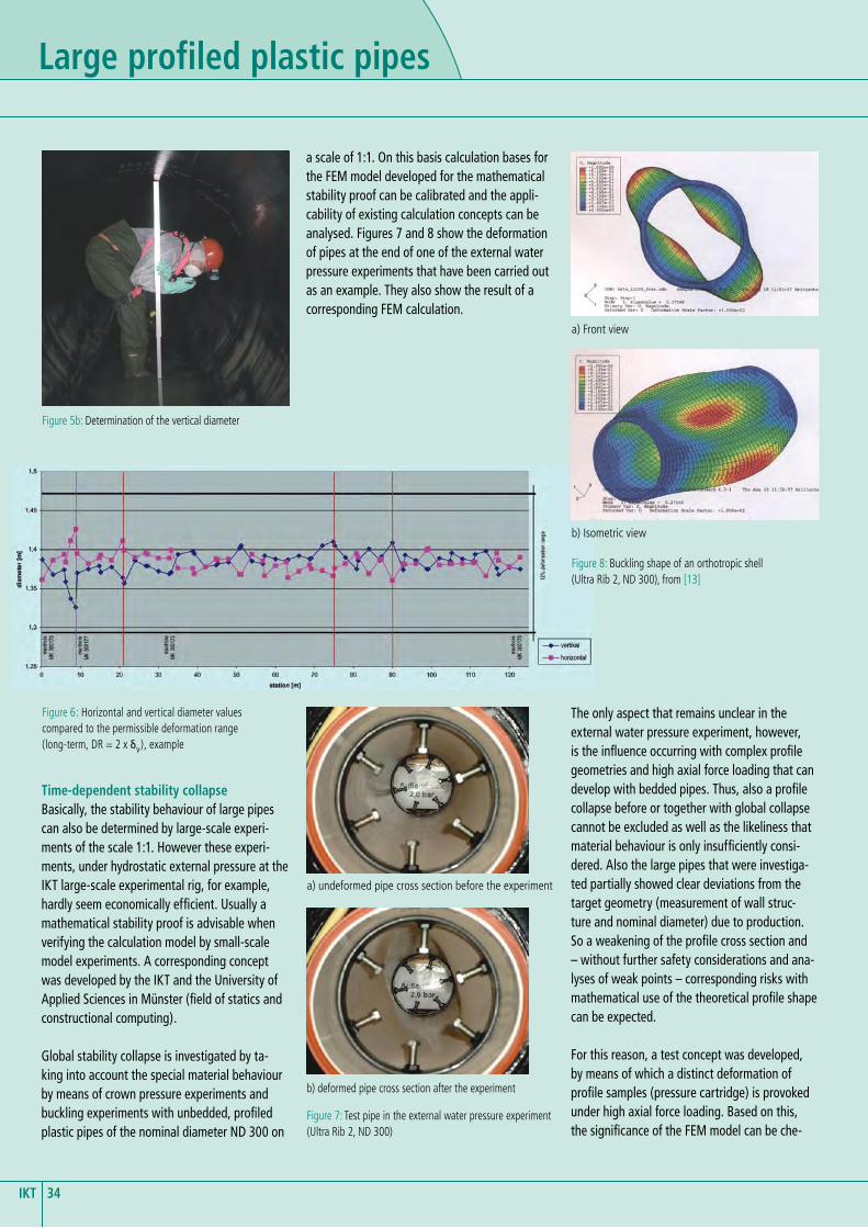
a scale of 1:1. On this basis calculation bases for the FEM model developed for the mathematical stability proof can be calibrated and the appli-cability of existing calculation concepts can be analysed. Figures 7 and 8 show the deformation of pipes at the end of one of the external water pressure experiments that have been carried out as an example. They also show the result of a corresponding FEM calculation.
The only aspect that remains unclear in the external water pressure experiment, however, is the influence occurring with complex profile geometries and high axial force loading that can develop with bedded pipes. Thus, also a profile collapse before or together with global collapse cannot be excluded as well as the likeliness that material behaviour is only insufficiently consi-dered. Also the large pipes that were investiga-ted partially showed clear deviations from the target geometry (measurement of wall struc-ture and nominal diameter) due to production. So a weakening of the profile cross section and – without further safety considerations and ana-lyses of weak points – corresponding risks with mathematical use of the theoretical profile shape can be expected.
For this reason, a test concept was developed, by means of which a distinct deformation of profile samples (pressure cartridge) is provoked under high axial force loading. Based on this, the significance of the FEM model can be che-
Figure 5b: Determination of the vertical diameter
Figure 6: Horizontal and vertical diameter values compared to the permissible deformation range (long-term, DR = 2 x δV), example
a) undeformed pipe cross section before the experiment
b) deformed pipe cross section after the experiment
Figure 7: Test pipe in the external water pressure experiment (Ultra Rib 2, ND 300)
Figure 8: Buckling shape of an orthotropic shell (Ultra Rib 2, ND 300), from [13]
a) Front view
b) Isometric view
�5 IKT
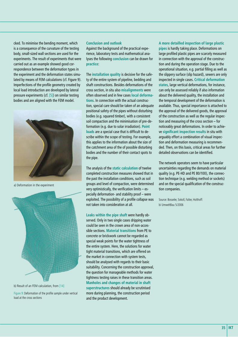
cked. To minimise the bending moment, which is a consequence of the curvature of the testing body, small-sized wall sections are used for the experiments. The result of experiments that were carried out as an example showed good cor-respondence between the deformation types in the experiment and the deformation states simu-lated by means of FEM calculations (cf. Figure 9). Imperfections of the profile geometry created by local load introduction are developed by lateral pressure experiments (cf. [5]) on similar testing bodies and are aligned with the FEM model.
Figure 9: Deformation of the profile sample under vertical load at the cross sections
a) Deformation in the experiment
b) Result of an FEM calculation, from [14]
Conclusion and outlookAgainst the background of the practical expe-rience, laboratory tests and mathematical ana-lyses the following conclusion can be drawn for practice:
The installation quality is decisive for the safe-ty of the entire system of pipeline, bedding and shaft constructions. Besides deformations of the cross section, in situ also misalignments were often observed and in few cases local deforma-tions. In connection with the actual construc-tion, special care should be taken of an adequate positional safety of the pipes without disturbing bodies (e.g. squared timber), with a consistent soil compaction and the minimisation of pre-de-formation (e.g. due to solar irradiation). Point loads are a special case that is difficult to de-scribe within the scope of testing. For example, this applies to the information about the size of the catchment area of the of possible disturbing bodies and the number of their contact spots to the pipe.
The analysis of the static calculation of twelve completed construction measures showed that in the past the installation conditions, such as soil groups and level of compaction, were determined very optimistically, the verification limits – es-pecially deformation- and stability proof – were exploited. The possibility of a profile collapse was not taken into consideration at all.
Leaks within the pipe shaft were hardly ob-served. Only in two single cases dripping water could be seen in the crown area of non-acces-sible sections. Material transitions from PE to concrete or brickwork cannot be regarded as special weak points for the water tightness of the entire system. Here, the solutions for water tight material transitions, which are offered on the market in connection with system tests, should be analysed with regards to their basic suitability. Concerning the construction approval, the question for manageable methods for water tightness testing raises in these transition areas. Manholes and changes of material in shaft superstructures should already be scrutinised more during planning, the construction period and the product development.
A more detailled inspection of large plastic pipes is hardly taking place. Deformations on large profiled plastic pipes are scarcely measured in connection with the approval of the construc-tion and during the operation stage. Due to the operational situation, e.g. partial filling as well as the slippery surface (slip hazard), sewers are only inspected in single cases. Critical deformation states, large vertical deformations, for instance, can only be assessed reliably if also information about the delivered quality, the installation and the temporal development of the deformation is available. Thus, special importance is attached to the approval of the delivered goods, the approval of the construction as well as the regular inspec-tion and measuring of the cross section – for noticeably great deformations. In order to achie-ve significant inspection results in situ with arguably effort a combination of visual inspec-tion and deformation measuring is recommen-ded. Then, on this basis, critical areas for further detailed observations can be identified.
The network operators seem to have particular uncertainties regarding the demands on material quality (e.g. PE-HD and PE 80/100), the connec-tion technique (e.g. welding method or sockets) and on the special qualification of the construc-tion companies.
test – Hausanschluss-Liner; final report of the IKT - Institute for Undergorund Infrastructure (November 2005), download on www.ikt.de.
[2] Bosseler, B.; Liebscher, M.: Erneuerung mit dem Berstverfahren: Bemessung, Prüfung und Qualitätssicherung von Abwasser-rohren; final report of the IKT - Institute for Underground Infrastructure by order of the Ministry for Environment and Nature Protec-tion, Agriculture and Consumer Protection of NRW (November 2003).
[3] Bosseler, B.; Schlüter, M.: Qualitätseinflüsse Schlauchliner; Stichproben-Untersuchung an sanierten Abwasserkanälen; final report of the IKT - Institute for Underground Infrastructure by order of the Ministry for Environment and Nature Protection, Agri-culture and Consumer Protection of NRW (December 2003), download on www.ikt.de.
[4] Bosseler, B.: Beitrag zur Darstellung, Analyse und Interpretation von Verfor-mungsmessdaten aus der Inneninspektion biegeweicher Abwasserleitungen. Tech-nisch-wissenschaftliche Berichte, IKT-Bericht 97/4 (June 1997).
[5] Bosseler, B.; Sokoll, O.: Profilierte Großrohre aus Kunststoff – Praxiserfahrungen und Prüfkonzepte; final report of the IKT - Insti-tute for Underground Infrastructure by order of the Ministry for Environment and Nature Protection, Agriculture and Consumer Protection of NRW (Oktober 2005).
[6] Berger, C.; Lohaus, J.: Zustand der Kanali-sation, Ergebnisse der DWA-Umfrage 2004; KA -Abwasser, Abfall (2005), Issue 5, pp. 528-539.
[7] Company information bauku - Troisdorfer Bau- und Kunststoff GmbH, Wiehl-Drabenderhöhe.
[8] Company information Frank & Krah Wickelrohr GmbH, Schutzbach.
[9] Company information Henze GmbH, Troisdorf.
[10] Regulations of the Deutschen Vereinigung für Wasserwirtschaft, Abwasser und Abfall e.V. (DWA), Standard A 127: Statische Berechnung von Abwasserkanälen und -leitungen, 3rd edition, Hennef, GFA (August 2000).
[11] Falter, B.; Holthoff, F.: Statiken für profilierte Rohre; Report of the Münster University of Applied Sciences / Department of civil engineering by order of the IKT - Institute for Underground infrastructure; Münster (November 2004, unpublished).
[12] Regulations of the Deutschen Vereinigung für Wasserwirtschaft, Abwasser und Abfall e.V. (DWA), Standard A 127: Statische Berechnung von Abwasserkanälen und -leitungen, 3rd edition, Hennef, GFA (August 2000).
[13] Falter, B.; Holthoff, F.: FEM-Berechnungen zum Beulverhalten von außen profilierten Rohren der Nennweite DN 300; Report of the Münster University of Applied Sciences / Department of civil engineering by order of the IKT - Institute for Underground infrastructure; Münster (September 2004, unpublished).
[14] Falter, B.; Holthoff, F.: FEM-Berechnungen zum Beulverhalten von profilierten Rohren der Nennweite DN 2000; Report of the Münster University of Applied Sciences / Department of civil engineering by order of the IKT - Institute for Underground Infrastructure; Münster (September 2004, unpublished).
�6IKT
aBOUt iKt
Published: April 2008
Circulation: 5.000 copies
Protective charge: 19,95 e
The initial funding for setting up the institute has been provided by the Ministry for the Environment of the State of
North-Rhine Westphalia, Germany‘s largest federal state.
However, IKT is not owned by the Government. Its owners are two associations which are
again non-profit organizations of their own:
a) IKT-Association of Network Operators: Members are about 100 cities, among them Berlin,
Hamburg, Cologne and London (Thames Water). They hold together 66.6% of IKT.
b) IKT-Association of Industry and Service Providers: Members are about 60 companies.
They hold together 33.3% of IKT.
You can find information on projects and services at:
www.ikt.de
IKT - Institute for Underground Infrastructure is a research, consultancy and testing institute speciali-zed in the field of sewers. It is neutral and indepen-dent and operates on a non-profit basis. It is oriented towards practical applications and works on issues surrounding underground pipe construction. Its key focus is centred on sewage systems. IKT provides scientifically backed analysis and advice.
IKT has been established in 1994 as a spin-off from Bochum University, Germany.