Technical Information Practical implementation of IEC 61508 ProSafe TI 48A02D00-00E-N Yokogawa System Center Europe B.V. PO Box 20020, 7302 HA, Apeldoorn, The Netherlands Tel.: (31) 55-5389 500 Fax.: (31) 55-538 9511 TI 48A02D00-00E-N !Copyright 20031stEdition September 2003
All Rights Reserved. !Copyright Yokogawa System Center Europe B.V. TI 48A02D00-00E-N September 2003
Table of Contents
1 Practical implementation of the IEC 61508 safety standard ..........................................................5 2 The IEC 61508 standard.....................................................................................................................6
3 The lifecycle steps ...........................................................................................................................11 3.1 Hazard and risk analysis..........................................................................................................11 3.2 Carry out risk assessment analysis .........................................................................................11 3.3 Safety Requirements Specification ..........................................................................................12
3.3.1 The design of the Safety Instrumented Functions.........................................................13 3.3.2 Failure modes and PFD calculation...............................................................................14 3.3.3 System Architecture.......................................................................................................17
3.4 Overall planning .......................................................................................................................20 3.5 Realisation of the SIS...............................................................................................................20 3.6 Installation, commissioning and validation...............................................................................20 3.7 Operation, maintenance and repair .........................................................................................21 3.8 Modification and retrofit............................................................................................................21
4 Conclusions......................................................................................................................................22 5 References ........................................................................................................................................23 List of Figures
Figure 1 The Safety Lifecycle (source: IEC-61508-1 figure 2).......................................................7 Figure 2 Practical Flow Chart Work Sequence..............................................................................8 Figure 3 A safety instrumented function ......................................................................................10 Figure 4 Risk reduction (source: IEC61508-5 figure A1) .............................................................12 Figure 5 Multiple SIFs within a SIS..............................................................................................14 Figure 6 Basic sensor configurations...........................................................................................18 Figure 7 Basic final element configurations .................................................................................19 Figure 8 Initiating modifications ...................................................................................................21 List of Tables
Table 1 Safety integrity levels: target failure measures for a SIF, allocated to a SIS operating inlow demand mode of operation .....................................................................................15
Table 2 Hardware Safety integrity: architectural constraints on subsystems build from type A
Table 3 Hardware Safety integrity: architectural constraints on subsystems build from type Bcomponents ...................................................................................................................18
All Rights Reserved. !Copyright Yokogawa System Center Europe B.V. TI 48A02D00-00E-N September 2003
1 Practical implementation of the IEC 61508 safety standard
IEC 61508 is the international standard issued by IEC, the International ElectrotechnicalCommission in 1999. It is the first general international standard regarding functional
safety of electrical/electronic/programmable electronic safety-related systems.For plant owners, setting adequate safety management is indispensable. If an accidentoccurs and the safety related systems do not comply with the standard, the companymight be accused for neglecting the appropriate safety rules. Accordingly using adequateshutdown systems and proper engineering which are conforming to the internationalstandard and explicable for later inspection are truly essential for users and engineeringcontractors. Users and engineering contractors are aware of this situation, since more andmore of the “requests for quotations” for safety systems are now demanding compliancewith IEC 61508 standard or the more process oriented IEC 61511 standard.
The term Safety Instrumented System (SIS) is introduced in the safety standards. Itcomprises all equipment, from sensors via logic solver up to the final elements to perform
the risk reduction, as required to operate the plant is a safe way.The IEC 61508 safety standard starts with the determination of the process risks duringthe Hazard analysis and the following risk assessment. All required safety functions needto be documented in a Safety Requirement Specification, including the sensor and valveconfigurations. The supplier of the safety system will start with the design of the SIS basedon this specification.
Also the safety validation after installation and commissioning and the periodic manualproof tests, as well as the inevitable changes during operation, are covered by thestandard. All the decisions, actions and results from beginning to end need a recordedauditable trail.
This TI introduces the practical sequential steps and measures that need to be taken by
users, engineering contractors and suppliers to comply with the standard. The choicesand consequences for the input sensors, type of logic solver and safety valves are alsodiscussed.
All Rights Reserved. !Copyright Yokogawa System Center Europe B.V. TI 48A02D00-00E-N September 2003
2 The IEC 61508 standard
The IEC 61508 presents a systematic method to draw up all process related risks, thedefinition of measures to be taken, and it has special emphasis on the design and
validation of safety related systems. This is all founded on the implementation of a fit forpurpose Functional Safety Management System. The standard introduces a life cycleconcept, including a method to establish the required Safety Integrity Level (SIL) for thetype of operation. The focus is in general more directed to an integral safety and riskmanagement approach, and it tends to see the requirements for a SIS as a last layer ofdefence.
This is rather new and the need for knowledge, education and training is eminent. Fromcontacts with the industry, it appeared that there is a growing need for advice and supportwith the implementation of the IEC-61508 standard and the IEC-61511 standard.
The IEC 61508 standard includes seven parts:
Part 1 General requirementsPart 2 Requirements for E/E/PES safety related systemsPart 3 Software requirementsPart 4 Definitions and abbreviationsPart 5 Examples of methods for determination of safety integrity levelsPart 6 Guidelines on the application of part 2 and part 3Part 7 Overview of techniques and measures
Parts 1, 2, 3 and 4 are normative, parts 5, 6 and 7 are for information only.
Fundamental to IEC 61508 is the safety lifecycle, which (see figure 1) covers not merely asystem’s development, but all the principal phases of its existence.The safety lifecycle approach demands a reconsideration of the way instrumented safety
is handled by all involved parties: Engineering Contractor – Suppliers – Integrators –Users.
The standard emphasis on four main aspects:
• Safety lifecycle• Management of functional safety• Pipe to pipe approach• Quantitative safety assessment
Each of these aspects will be discussed briefly in the next paragraphs.
As part of the safety management the standard emphasis the importance to document allthe steps of the life cycle, so that it becomes completely auditable, e.g. for an externalcertifying body. Also the competence of organizations and people involved in the life cyclemust be included.
All Rights Reserved. !Copyright Yokogawa System Center Europe B.V. TI 48A02D00-00E-N September 2003
2.1 Safety Lifecycle
The safety lifecycle concept as given in figure 1 presents a logical sequence for the mainactivities to be executed.
10 11
NOTE 1 Activities relating toverification , management of functional safety and functional safety assessment arenot shown for reasons of clarity but are relevent to all overall, E/E/PES and software safety lifecycle phases.
NOTE 2 The phases represented by boxes 10 and 11 are outside the scope of this standard.
NOTE 3 Parts 2 and 3 deal with box 9 (realisation) but they also deal, where relevant, with the programmable electronic(hardware and software) aspects of boxes 13, 14 and 15.
Concept1
Overall scope
definition2
Hazard and riskanalysis3
Overall safety
requirements4
Safety requirements
allocation5
Back to appropriate
overall safety lifecycle
phase
Overall safetyvalidation13
Overall operation,
maintenance and repair
Overall modificationand retrofit14 15
Decommissioning
or disposal16
Safety-related
systems:
E/E/PES
Realisation(see E/E/PES
safetylifecycle)
9Safety-related
systems:
other
technology
Realisation
Overall installation
and commissioning12
8
Overall planning
OveralI
operation and
maintenance
planning
OveralI
installation and
commissioning
planning
Overall
safety
validation
planning
6 7 8
External risk
reduction
facilit ies
Realisation
Figure 1 The Safety Lifecycle (source: IEC-61508-1 figure 2)
In some companies a certain functional safety management system will already beinstalled, mostly conforming to the IEC requirements, but not always following thelifecycle. The next chapter describes all steps from the lifecycle. Figure 2 shows thepractical sequential steps including the documentation to be produced in each step todetermine the safety functions, to design the safety loops and to install and maintain
All Rights Reserved. !Copyright Yokogawa System Center Europe B.V. TI 48A02D00-00E-N September 2003
2.2 Functional Safety Management system
This may be the most difficult, and the most under-estimated part of the standard. Allcompanies involved in any step of the life cycle must have a functional safetymanagement system (FSM) in place.
It should specify all management and technical activities that are necessary to achieve therequired functional safety. It will show the used lifecycle, the procedures to be used, thecompetences and responsibilities of all persons, department and organisations, the wayverification and validation is handled, and so on.
And everything need to be executed in such a way that it is auditable and that all thedecisions made are traceable.
Documentation
The normative measures on documentation in the new safety standard are very strict andextensive.
There is the requirement to document (in written papers, computer files, etc) all stepstaken in the life cycle. All the design and engineering decisions and justifications have tocarefully documented or recorded. An audible trail of all the activities and results have tobe carefully organised.
Competence
All organizations involved in the lifecycle must provide evidence that they are competentfor the tasks for which they are responsible.
All the managers, project leaders and engineers who are involved in the design,engineering and integration phases need to have adequate experience and training.Company standards for education and training must be compiled, and regular trainingmust be scheduled.
Yokogawa SCE has been audited and certified by TÜV, Germany, with respect to the wayshe has implemented the requirements of the IEC61508 standards into her organization,and the way safety related projects are executed
2.3 Pipe to pipe approach
The standard prescribes that the complete safety loop should be considered. The loopnormally comprises initiating devices (sensors, transmitters, isolators), a logic solver(inputs, protection/voting logic, outputs) and final elements (valves, contactors), see figure3 below. Currently some users still think that just purchasing a safety certified PLC isenough to fulfil all the safety requirements of their system. They tend to forget consideringabout other SIS components. For example, there are still shutdown systems in serviceconnected to pulse-energized valves. This is a potentially dangerous situation in case ofloss of power.
The standard requires a pipe-to-pipe safety approach in which all parts of the safety loopare considered as part of the safety lifecycle. This is a comprehensive approach, becausesensors, inputs, logic solver, outputs and final elements are all vital links in the samesafety chain. Therefore dedicated sections in the standard specify the requirements forfield devices and interfaces.
In practice valves will contribute mostly to the un-safety, (50%), followed by sensors(35%). The logic solver in an average configuration will contribute only 15%, and ofteneven less.
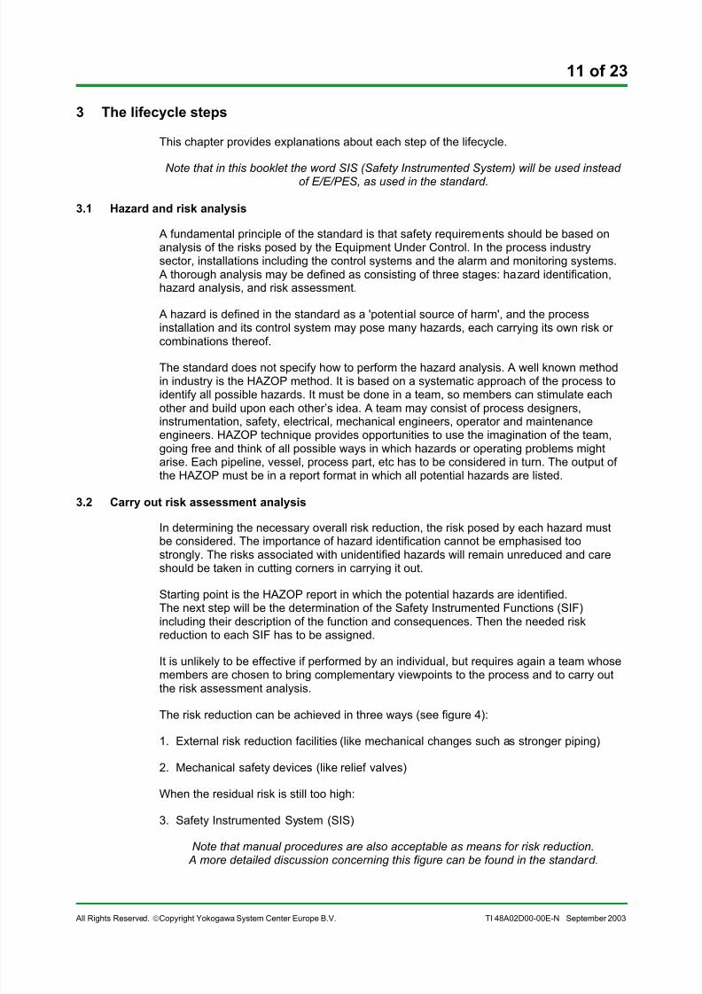
In the standard several ways to perform the SIL assessment and to quantify the requiredrisk reduction are mentioned:
• ALARP• Risk Matrix• Risk Graph• Fault Tree Analysis• Layers Of Protection Analysis
All methods are based on an expected process demand rate. If no risk reductionmeasures are taken, every process demand would cause a hazard. The expectedconsequences of the hazard without protection will be analysed, and the required upperlimit of the acceptable risk will be defined.
According to the standard the risk assessment analysis will result into a certain number ofSIFs each with their individual target SIL. Installed or to be installed “other technologysafety-related systems” like mechanical relief valves or rupture disks, if properly designed,are able to reduce the target SIL of the SIF.
The implementation of SIFs by means of a practical SIS including the selection of sensors,safety valves, logic solver and the calculation of the PFD of each SIF (to compare with the
target SIL) is described in the next sections.
3.3 Safety Requirements Specification
All the requirements for each safety function must be documented. Both the functionalrequirements and the required SIL must be specified. Note that this should be done foreach individual loop.
It is not enough to order a “SIL3 PLC” and think that you are in compliance with the IEC-61508.
The following list gives some items that must be covered, in the new IEC-61511 standarda more extensive list can be found.
All Rights Reserved. !Copyright Yokogawa System Center Europe B.V. TI 48A02D00-00E-N September 2003
• Description of the safety functions• Target SIL• Safe state (open / closed, de-energized / energized)• Process safety time (and the derived system response time)• Overrides (maintenance, operational)• Operator interfaces• Relevant modes: start-up, steady operation, shut down.• Foreseeable abnormal conditions• Requirements for starting-up and shutting-down• Etc.
When preparing the SRS some realisation related items must be taken into accountalready. These are:
• Safety Loops (SIFs)• System architecture• Failure modes and PFD calculation
These items will be discussed in the following sections.
3.3.1 The design of the Safety Instrumented Functions
A SIF will contain a number of “devices” and all these devices together build up the SIS. ASIS normally comprises more then one SIF.
Definition of Safety Instrumented Function (IEC 61508/61511): “Function to beimplemented by a SIS who is intended to achieve or maintain a safe state for the Processin respect to a specific hazardous event.”
The following devices, functions, and energy sources can belong to, or are connected witha SIF:
1. Sensors (digital devices such as limit switches, analogue transmitters)
2. Field interface like IS isolators
3. Logic solver (programmable or non programmable with I/O modules)
4. Final elements like solenoids – safety valves – contactors (motor starters)
5. Safety communication
6. Wiring
7. Electric power
8. Instrument air
9. Maintenance overriding circuits
10. Start-up overriding circuits
11. Start-up logic and timing functions
12. Alarm and indication circuits
13. Status and/or sequence of event monitoring circuit, links
All Rights Reserved. !Copyright Yokogawa System Center Europe B.V. TI 48A02D00-00E-N September 2003
Item 1 to 6 are important devices in the SIF, item 7 & 8 are the energy sources and item 9to 14 are the auxiliary functions that either need to have the same integrity level as thetarget SIL or shall be safety interference free. Item 14 needs special attention. This alarmsignal to the operator indicates that the logic solver is no longer able to perform itsintended safety functions and the operator has to follow the particular instructions (mostly
to shutdown the process manually). This alarm signal path needs to have the same SIL asthe related target SIL of the SIF. This means that a normal serial link to the control systemand an alarm message on the HMI screen should not be used!
A SIF can consist of multiple sensors and a single safety valve or one sensor with morethan one safety valve. Any combination is possible. See figures 5.
sensor
final
element
logic
solver
sensor
sensor
final
element
final
element
final
element
sensor
sensor
SIF #1 (e.g. SIL 4)
SIF #2 (e.g. SIL 3)
SIF #4 (e.g. SIL 2)
SIF #5 (e.g. SIL 1)
triple voted
Safety Instrumented System
SIF #3 (e.g. SIL 3)
#2
#3
#5
#4
dual voted
#1
Figure 5 Multiple SIFs within a SIS
For each SIF the required SIL must be specified in the SRS.
The standard does not mention availability of the SIS. Normally the availability iscalculated for the complete SIS, and not per SIF.
3.3.2 Failure modes and PFD calculation
Safety Integrity Levels
Part 1 table 2 of the IEC 61508 specifies four SILs, which are succeeding ranges eachcomprising a tenfold probability scale factor. The SIL of a SIF will be expressed as“Probability of a Failure on Demand (PFD)”. A demand is given when one of the processparameters exceeds its safety limit. As a result a request for the safety system to shutdown the process is given. If a demand occurs and the safety system is not able toperform at that time a hazardous event will arise.
The mathematical interpretation of the PFD is the average probability of having adangerous undetected failure in the SIF.
The standard defines the SIL for the complete SIF only and not for the individual devices
All Rights Reserved. !Copyright Yokogawa System Center Europe B.V. TI 48A02D00-00E-N September 2003
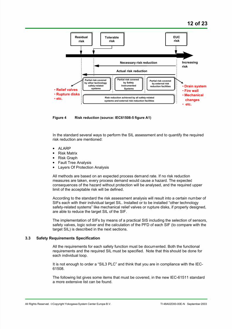
Table 1 gives an overview of the four safety levels for “low demand mode” processes.“Low demand mode” means less than one demand per year. It is the practical situation inthe process industry.
Table 1 Safety integrity levels: target failure measures for a SIF, allocated to a SIS
operating in low demand mode of operationSafety
Integrity
Level
Average probability of failure to perform its design
function on demand
(Low demand mode of operation)
4 ! 10-5 to < 10-4 3 ! 10-4 to < 10-3 2 ! 10-3 to < 10-2 1 ! 10-2 to < 10-1
Design principles
The recommended design principle for realising SIFs will be the “De-energized To Safe
(DTS)” principle. With this principle, it is possible to reach SIL 4 with the right devices andarchitecture.
In this method all the devices in the loop are active (contacts are closed, current isrunning, instrument air is available to keep the safety valve open, etc). The energysources like electrical power and instrument air do not play a role in the SIL but only withrespect to the False Trip Rate (FTR), because a failure in the supply causes a trip. ThisFTR parameter is not a part of the standard, but it is important for system availability andalso for human confidence in the safety system.
In case the “Energized To Safe (ETS)” principle has to be applied (for example, certainBlow-down and Fire & Gas applications) a higher SIL than 1 will be very difficult to realize.
One reason is that the chance of unavailability of electrical power or instrument air has tobe smaller than once in 100-years, which is very difficult to prove. Another reason is thatthe devices contain normally more failures that force or keep the output de-energized thenthe other way around. To perform the SIF both energies have to be available. Any losewire or open circuit inhibits the safety function. Extensive redundancy and monitoringcircuits are able to reduce the unavailability.
Failure modes
In the safety engineering, failures can be divided in two types:
1. Safe failures: failures that do not influence the safety integrity, but cause a nuisanceaction
2. Dangerous failures: failures that obstruct the safe performance of the SIF.
With built-in diagnostic functions it is often possible to detect a part of the dangerousfailures and to take appropriate action (e.g. change over to a redundant system, alarm theoperator, shut down). In case such action is taken, we consider that the dangerous failurehas changed to a safe failure.
The remaining dangerous undetected failures are the ones that determine the unsafety ofthe SIF, and these failures are used the PFD calculation.
Note that only the random hardware failures are included in the PFD calculation.Systematic failures (like: software, engineering & design, production failures) and human
failures (e.g. operator mistakes) are not included. But the standard does require that onehas taken certain measures to minimize this kind of failures.
All Rights Reserved. !Copyright Yokogawa System Center Europe B.V. TI 48A02D00-00E-N September 2003
Necessary calculation parameters
To perform the reliability calculation of each SIF, one needs to know from each device inthe loop the following parameters:
1. Dangerous failure rate2. Diagnostic coverage factor for dangerous failures
3. Coverage factor of validation and proof testing
4. Desired proof test interval
5. Safe failure rate
6. Diagnostic coverage factor for safe failures
7. False Trip Rate (FTR)
8. Mean Time To Repair
The first four items are used to calculate the PFD.
The items 5-8 are used to calculate the FTR and the availability. The standard does notspecify any requirements for this. But most end users are also interested in this figurebecause a false trip causes economic losses.
False trips can be caused by all kinds of process, mechanical or electrical equipmentfailures. To minimize the chance of a false trip, dual process units can be used. The falsetrips caused by the SIS have to be in balance with the availability specification of theprocess.
Proof testing
In order to achieve the required SIL, proof tests at regular intervals might be necessary todiscover (and repair) undetected dangerous failures.
During this proof test all relevant devices in the safety loop are tested. An adequatemanual proof test with a high coverage factor can be performed if the particular device is“off-line”. This often means a production stop in case of a single production unit.Redundant process installations, specific redundant sensor and valve configurations are amethodology to avoid production stops for manual proof testing. An alternative is to useequipment with a lower dangerous failure rate.
Common Cause
In redundant system configurations common cause failures should be considered.
A stressor (for example electromagnetic interference) can cause a multiple failure in theredundant parts. If that is the case, some or all identical modules in a redundantconfiguration can be affected at the same time.
The common cause factor is expressed as a percentage of the total number of failures. Itcomprises a relative small part of the total number of failures (between 0.1 and 5 %).
The influence of the common cause failure will be an increase of the undetecteddangerous failures and as a result cause a lower safety integrity (higher PFD).
All Rights Reserved. !Copyright Yokogawa System Center Europe B.V. TI 48A02D00-00E-N September 2003
Reliability data and calculation methodology
Reliability data of a device can be obtained from the manufacturer, OREDA database orother databases, own company field data, other company field data, etc.
Practically it does not matter what the source is; the used data always need to be checkedand to be compared with other available data. An important factor will be the justificationof the used data and consistency in the organisation. Any process and circumstance isdifferent from another and for every device a written (-recorded) application type
justification is needed. This justification is a dominant normative demand in the standard.
The standard contains some examples how to calculate the PFD. In practice there aremore methods, see also the IEC-61511 and the ISA-84 standard.
Well known safety calculation methods are:
• Formulas
•
Fault tree analysis
• Markov analysis
Each method has its own group of supporters. For an average safety function the resultsof all methods should lead to about the same figure.
3.3.3 System Architecture
Depending on the target SIL and the Safe Failure Fraction (SFF) of the used equipment,the IEC 61508 has specific requirements on the minimum redundancy.
SFF is defined as the ratio of the failure rate of safe plus detected failures in a functional
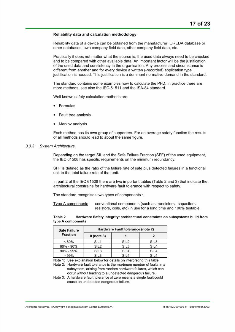
unit to the total failure rate of that unit.In part 2 of the IEC 61508 there are two important tables (Table 2 and 3) that indicate thearchitectural constrains for hardware fault tolerance with respect to safety.
The standard recognises two types of components :
Type A components conventional components (such as transistors, capacitors,resistors, coils, etc) in use for a long time and 100% testable.
Table 2 Hardware Safety integrity: architectural constraints on subsystems build from
> 99% SIL3 SIL4 SIL4Note 1: See explanation below for details on interpreting this tableNote 2: Hardware fault tolerance is the maximum number of faults in a
subsystem, arising from random hardware failures, which canoccur without leading to a undetected dangerous failure.
Note 3: A hardware fault tolerance of zero means a single fault couldcause an undetected dangerous failure.
Hardware fault tolerance means that, for example, one sensor (1oo1) can tolerate zero
undetected dangerous failure. Two in series connected sensors (1oo2) can tolerate oneundetected dangerous failure. Three in series connected sensors (1oo3) can tolerate twoundetected dangerous failures.
There are “smart” valves and solenoids on the market with built in automatic diagnostics.They belong to the B type subsystems if microprocessors are involved. The SFF has to becertified by independent authorities with the right skills and equipment.
Sensors
Selecting the right sensors for a particular application is in the first place a matter of:
• Type of process and process conditions.
• Preference concerning company standard (available stock), field experience, availableand justifiable reliability data.
Analogue transmitters have a better reliability reputation than digital pressure and levelswitches.
Continuous transmitter validation is possible by comparing dynamic behaviour of theanalogue or digital signals. Both reasons are the justification that analogue transmittersare used widely for safety applications these days.
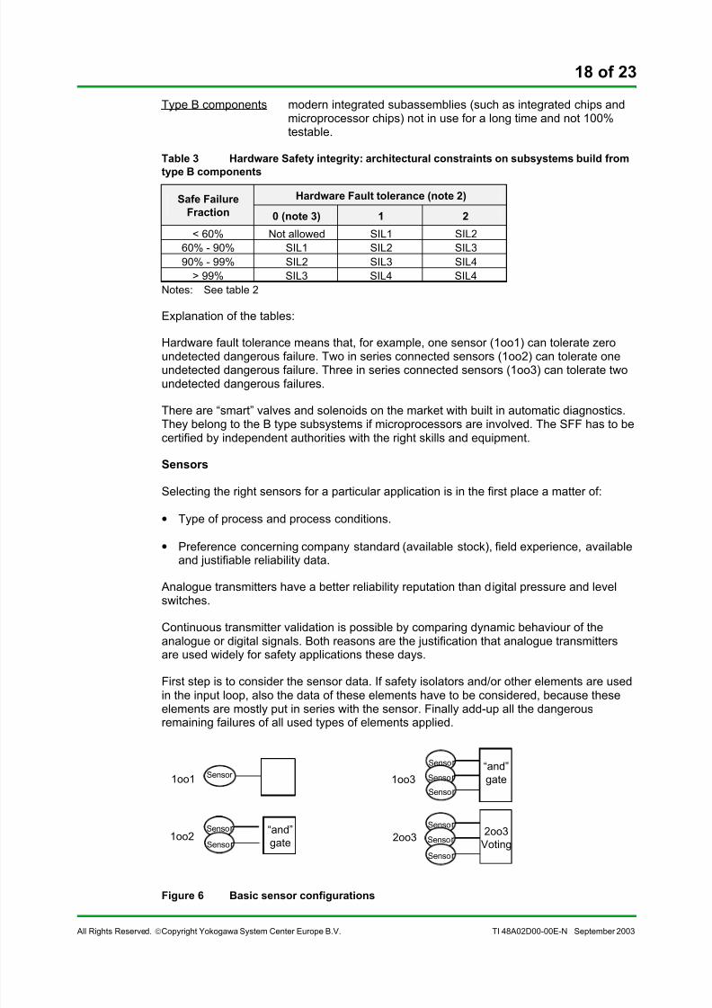
First step is to consider the sensor data. If safety isolators and/or other elements are usedin the input loop, also the data of these elements have to be considered, because these
elements are mostly put in series with the sensor. Finally add-up all the dangerousremaining failures of all used types of elements applied.
All Rights Reserved. !Copyright Yokogawa System Center Europe B.V. TI 48A02D00-00E-N September 2003
The 1oo2 and 1oo3 sensor configurations in figure 6 are only to lower the PFD of the inputsensor plus other possible serial elements.
The FTR will become higher if two or three sensors are put in series.
The 2oo3 sensor configuration has the advantages of both: two sensors in parallel (lowerFTR) and two sensors in series (lower PFD).
Example 1: Use of an ordinary “smart” analogue transmitter.
Applying table 3 of the minimum redundancy requirements, three sensors in series willachieve SIL 2, because standard “smart” transmitters have mostly a SFF < 60 %.When using three Yokogawa EJA transmitters (SFF = 88%) it is possible to achieve SIL3according to the table.
Example 2: Use of conventional analogue transmitters for a SIL 3 SIF
Applying table 2 of the minimum redundancy requirements, three sensors in series will
achieve SIL 3 (Assuming SFF < 60%). The FTR will be high in this situation. After having consulted these tables PFD calculations have to demonstrate that therequired SIL is achieved.
Final Elements
The most used final element device is the shutdown valve. Also contractors or “starters” tostart and stop motors are used. Most safety valves are powered by instrument air and tocontrol this power medium, solenoids need to be installed. These solenoids are mostlythree-way electrical valves. If energised the instrument air will pass and keep the safetyvalve open. To close the valve the air has to be released and a spring is closing the valve.The failure rates and types of the solenoids have to be add-up with the failure rates of thesafety salve.
Sometimes a dual parallel/serial solenoid combination is used to lower the FTR and toincrease the safety integrity. In figure 7 some basic safety valve configurations are shown.
Figure 7 Basic final element configurations
All the considerations concerning failure rate, type, FTR, PFD, etc are also applicable forfinal elements. This is including the minimum redundancy requirements table 2.
Most safety valves have no automatic diagnostic capability and the undetected dangerousfailure rate is high. They is often only feasible with a periodical proof test time of 1 year orshorter. There are special valve manufacturers who are producing highly reliableshutdown valves for large gas and oil installations. These valves, including a parallelsolenoid configuration, are applicable in SIL 2. Their aim is to reduce significantly the
All Rights Reserved. !Copyright Yokogawa System Center Europe B.V. TI 48A02D00-00E-N September 2003
Logic Solver
The logic solver is mentioned as last, as in practice it has much less influence on thecomplete safety loop compared to valves and sensors. Common practice learns that thelogic solver takes less than 15% of the SIL budget.
On the market there are several recognised manufactures that deliver certified safetysystems. The most common configurations are:
• Inherent failsafe (no software)• 1oo2D• 2oo3• 2oo4 (only CPUs)
All programmable systems have SIL2/3 certificates, issued by the well known certificationorganisations like German TÜV, Factory Mutual, Baseefa and others.
Yokogawa delivers Inherent failsafe systems (Prosafe-SLS®) and safety PLC’s with a
1oo1D or a 1oo2D architecture (Prosafe-PLC®
).
3.4 Overall planning
The end-user or the contractor has to prepare a planning for the complete plant. This willconsists of several parts :
• Overall Operation and Maintenance planning• Overall Safety validation planning• Overall Installation and Commissioning planning
3.5 Realisation of the SIS
A specialised safety supplier mostly takes care of the realisation of the SIS.
The standard has a separate chapter on hardware (Part 2) and on software (Part 3).The standard is applicable for the development and production of equipment that is part ofthe SIS and also on the use of that equipment to realise the SIS.
Most of the issues that are discussed in the chapter on SRS will be applied in detail duringthe realisation of the SIS.
3.6 Installation, commissioning and validation
The installation and commissioning of the SIS must be performed in accordance with theappropriate planning.
All activities have to be documented carefully. Also resolving of failures has to bedocumented.
After the commissioning bas been finished successfully, an overall validation must takeplace before the plant may start-up.This validation has to be performed in accordance with the overall validation plan.This validation will normally be performed by an independent assessor from a well knowncertifying body like DNV or Lloyds.
The purpose is to validate that the safety related systems meet the specification for theoverall safety requirements.Extensive documentation of activities and results is required.
All Rights Reserved. !Copyright Yokogawa System Center Europe B.V. TI 48A02D00-00E-N September 2003
3.7 Operation, maintenance and repair
During operation and maintenance data must be collected on failures, test results,demands, accidents, etc.
This data can be used to verify that the assumptions made during HAZOP were correct. And also to verify that the failure rates, as used in SIL calculations, were realistic.
When mismatches are discovered, (parts of ) the HAZOP and SIL calculations must be re-done. This might lead to modifications to the (safety) system.
Manual proof tests
After installing the devices in the field it might be necessary to perform periodical prooftests to check the existence of undetected dangerous failures which will increasegradually with time.The time between these test periods will be derived from the result of the reliabilitycalculations.
The coverage of a proof test in the field will often not be 100%, but between 75 to 100 %.Note also that repair never will be 100% correct.The result will be that after a certain number of proof tests during a number of years thedevice will not be longer able to perform its intended SIF with the required SIL.
The time between the proof tests and the device lifetime, before a total overhaul isneeded, shall be a part of the reliability calculation results.
Proof tests must be executed according to written procedures. The result of each prooftest must be documented and available for audits.
3.8 Modification and retrofit
When the system is in operation for some time, there will arise a need for modificationssooner or later. These modifications must be executed following the same stringent rulesas used during the original realisation of the SIS. The figure below gives an overview howto initiate modifications. During the impact analysis not only the existing plant has to beexamined, but also a list of all documents that need to be modified has to be prepared.
Impact analysis
study
Impact analysis
study
Modification
request
Modification
request
HAZOPHAZOP
AuthorizationAuthorization
Impact analysis
report
Impact analysis
report
Back to appropriate phase of the lifecycle
Operation/production requests New /amended legislation Modifications to the EUC Changes to the safety requirements
All Rights Reserved. !Copyright Yokogawa System Center Europe B.V. TI 48A02D00-00E-N September 2003
4 Conclusions
The design, engineering and installation sequence of a safety system for a process, newor revamp of an existing one will mostly have to be changed from the current practice to
become in compliance with the IEC 61508 standard.Especially the specification and design sequence, documentation, justification of all thedecisions concerning the safety integrity, and the audibility of all the performed activities,are important. Therefore an adequate Functional Safety Management System must be inplace.
The architectural rules as per IEC 61508 have to be considered in an early stage of theprocess engineering. The selection of the right type and number of sensors and safetyvalves to be used, has a serious influence on the process engineering phase andmechanical set-up. If performed too late in the design phase, major changes in themechanical set-up may be required at later point in time.
Performing the lifecycle activities of the Safety Instrumented Functions in the right time
and in connection with the remaining process engineering phases, will save money andavoid frictions and frustrations within the engineering contractor organisations.The experience and competence of a well known certified safety supplier like YokogawaSCE will enable the end-user and contractor to achieve their safety goals in line with theIEC 61508 safety standard.


![Comparison of software safety standards IEC 61508 …...specifically targets selected IEC I&C software safety standards IEC 61508-3 [8] and IEC 62138, which are introduced more extensively](https://static.documents.pub/doc/80x56/5ede2b4fad6a402d6669785a/comparison-of-software-safety-standards-iec-61508-specifically-targets-selected.jpg)


