Global | Select your country Practical Non-Uniform Channelization for Multistandard Base Stations - ZTE Corporation http://wwwen.zte.com.cn/endata/magazine/ztecommunications/2011Year/no4/articles/201202/t20120202_283027.html (1 of 22)05/09/2012 14:52:47 Home Solutions Cases Products & Services Press Center Support About ZTE Position: Home > magazine > ZTE Communications > 2011Year > No.4 > articles Practical Non-Uniform Channelization for Multistandard Base Stations 2012-02-02 Author:álvaro Palomo Navarro, Rudi Villing, and Ronan J. Farrell Abstract:A Multistandard software-defined radio base station must perform non-uniform channelization of multiplexed frequency bands. Non-uniform channelization accounts for a significant portion of the digital signal processing workload in the base station receiver and can be difficult to realize in a physical implementation. In non-uniform channelization methods based on generalized DFT filter banks, large prototype filter orders are a significant issue for implementation. In this paper, a multistage filter design is applied to two different non-uniform generalized DFT-based channelizers in order to reduce their filter orders. To evaluate the approach, a TETRA and TEDS base station is used. Experimental results show that the new multistage design reduces both the number of coefficients and operations and leads to a more feasible design and practical physical implementation. 1 Introduction Radio spectrum is typically allocated using coarse-grained frequency division multiplexing. Different radio standards are allocated independent and non- overlapping frequency bands that are reserved exclusively for each standard. This approach simplifies the radio design because each standard operates in isolation; however, available spectrum is not used optimally because reserved bands may be under-used some of the time. A more efficient alternative is to allow multistandard multiplexing of the frequency band. The frequency band is instead multiplexed among multiple radio standards [1]. Channels within the frequency band are dynamically allocated to the radio standards. If these channels do not have uniform bandwidth or center frequencies, as is typical for heterogeneous radio standards, then dynamic allocation is challenging.
Transcript
Global | Select your country
Practical Non-Uniform Channelization for Multistandard Base Stations - ZTE Corporation
http://wwwen.zte.com.cn/endata/magazine/ztecommunications/2011Year/no4/articles/201202/t20120202_283027.html (1 of 22)05/09/2012 14:52:47
Home Solutions Cases Products & Services Press Center Support About ZTE
Practical Non-Uniform Channelization for Multistandard Base Stations
2012-02-02 Author:álvaro Palomo Navarro, Rudi Villing, and Ronan J. Farrell
Abstract:A Multistandard software-defined radio base station must perform non-uniform channelization of multiplexed frequency bands. Non-uniform
channelization accounts for a significant portion of the digital signal processing workload in the base station receiver and can be difficult to realize in a physical
implementation. In non-uniform channelization methods based on generalized DFT filter banks, large prototype filter orders are a significant issue for
implementation. In this paper, a multistage filter design is applied to two different non-uniform generalized DFT-based channelizers in order to reduce their filter
orders. To evaluate the approach, a TETRA and TEDS base station is used. Experimental results show that the new multistage design reduces both the number
of coefficients and operations and leads to a more feasible design and practical physical implementation.
1 Introduction
Radio spectrum is typically allocated using coarse-grained frequency division multiplexing. Different radio standards are allocated independent and non-
overlapping frequency bands that are reserved exclusively for each standard. This approach simplifies the radio design because each standard operates in
isolation; however, available spectrum is not used optimally because reserved bands may be under-used some of the time. A more efficient alternative is to allow
multistandard multiplexing of the frequency band. The frequency band is instead multiplexed among multiple radio standards [1]. Channels within the frequency
band are dynamically allocated to the radio standards. If these channels do not have uniform bandwidth or center frequencies, as is typical for heterogeneous
radio standards, then dynamic allocation is challenging.
Practical Non-Uniform Channelization for Multistandard Base Stations - ZTE Corporation
In software-defined radio (SDR), analogue-to-digital and digital-to-analogue conversion is performed as close as possible to the antenna [2]. Most of the radio
components, now in the digital domain, are implemented on a reconfigurable platform. Reconfigurability makes SDR particularly suitable for working with
multistandard systems and for upgrading to future standards.
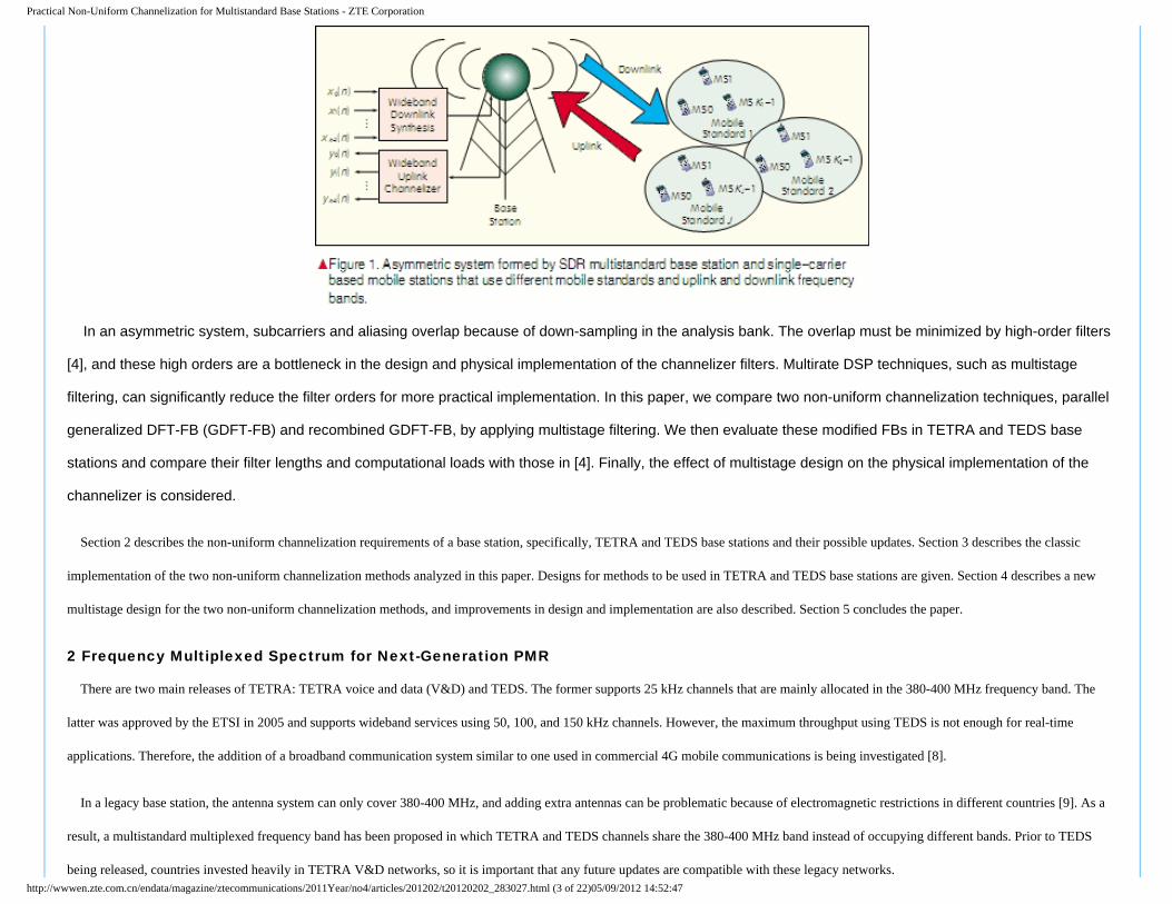
In an SDR base station (Fig. 1), the wideband uplink, which comprises all the mobile station channels, is digitally converted immediately after the RF front-end.
Multirate digital signal processing (DSP) is then used to filter and shift to baseband all the independent information channels. On the transmitter side,
complementary processing is carried out. Extraction of the uplink channels (channelization) is a bigger challenge than downlink synthesis because more stringent
filtering is required to avoid adjacent channel interference.
Different non-uniform channelization techniques have been described in [3]-[5]. In many cases, these techniques are based on combining or altering efficient
uniform channelization methods, such as uniform complex discrete Fourier transform (DFT) modulated transmultiplexers and tree quadrature mirror filter banks
(TQMFB) [6]. In these filter bank (FB) based structures, a synthesis bank multiplexes the channel frequency at the transmitter side, and an analysis bank
performs for equivalent channelization in the receiver. Such a structure is symmetric; that is, amplitude and phase distortion in one half of the FB are suppressed
in the complementary half, allowing perfect reconstruction. This approach includes multicarrier techniques such as OFDM. In contrast, the system in Fig. 1 has an
asymmetric design; that is, the uplink signal channelized by the analysis bank is not created by a complementary synthesis bank. The system comprises the
transmissions of independent mobile stations that are assumed to use single-carrier transceivers. The downlink is similarly asymmetrical. This structure allows the
base station to be compatible with legacy systems. A professional mobile radio (PMR) base station using the terrestrial trunked radio (TETRA) standard or its
high-speed derivative, TETRA enhanced data service (TEDS) [7], is a good application of this architecture.
http://wwwen.zte.com.cn/endata/magazine/ztecommunications/2011Year/no4/articles/201202/t20120202_283027.html (2 of 22)05/09/2012 14:52:47
Practical Non-Uniform Channelization for Multistandard Base Stations - ZTE Corporation
In an asymmetric system, subcarriers and aliasing overlap because of down-sampling in the analysis bank. The overlap must be minimized by high-order filters
[4], and these high orders are a bottleneck in the design and physical implementation of the channelizer filters. Multirate DSP techniques, such as multistage
filtering, can significantly reduce the filter orders for more practical implementation. In this paper, we compare two non-uniform channelization techniques, parallel
generalized DFT-FB (GDFT-FB) and recombined GDFT-FB, by applying multistage filtering. We then evaluate these modified FBs in TETRA and TEDS base
stations and compare their filter lengths and computational loads with those in [4]. Finally, the effect of multistage design on the physical implementation of the
channelizer is considered.
Section 2 describes the non-uniform channelization requirements of a base station, specifically, TETRA and TEDS base stations and their possible updates. Section 3 describes the classic
implementation of the two non-uniform channelization methods analyzed in this paper. Designs for methods to be used in TETRA and TEDS base stations are given. Section 4 describes a new
multistage design for the two non-uniform channelization methods, and improvements in design and implementation are also described. Section 5 concludes the paper.
2 Frequency Multiplexed Spectrum for Next-Generation PMR
There are two main releases of TETRA: TETRA voice and data (V&D) and TEDS. The former supports 25 kHz channels that are mainly allocated in the 380-400 MHz frequency band. The
latter was approved by the ETSI in 2005 and supports wideband services using 50, 100, and 150 kHz channels. However, the maximum throughput using TEDS is not enough for real-time
applications. Therefore, the addition of a broadband communication system similar to one used in commercial 4G mobile communications is being investigated [8].
In a legacy base station, the antenna system can only cover 380-400 MHz, and adding extra antennas can be problematic because of electromagnetic restrictions in different countries [9]. As a
result, a multistandard multiplexed frequency band has been proposed in which TETRA and TEDS channels share the 380-400 MHz band instead of occupying different bands. Prior to TEDS
being released, countries invested heavily in TETRA V&D networks, so it is important that any future updates are compatible with these legacy networks.http://wwwen.zte.com.cn/endata/magazine/ztecommunications/2011Year/no4/articles/201202/t20120202_283027.html (3 of 22)05/09/2012 14:52:47
Practical Non-Uniform Channelization for Multistandard Base Stations - ZTE Corporation
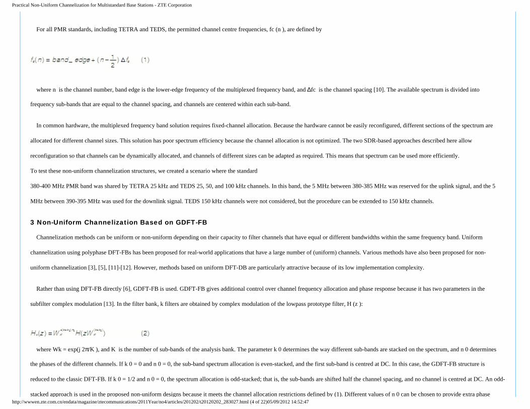
For all PMR standards, including TETRA and TEDS, the permitted channel centre frequencies, fc (n ), are defined by
where n is the channel number, band edge is the lower-edge frequency of the multiplexed frequency band, and ∆fc is the channel spacing [10]. The available spectrum is divided into
frequency sub-bands that are equal to the channel spacing, and channels are centered within each sub-band.
In common hardware, the multiplexed frequency band solution requires fixed-channel allocation. Because the hardware cannot be easily reconfigured, different sections of the spectrum are
allocated for different channel sizes. This solution has poor spectrum efficiency because the channel allocation is not optimized. The two SDR-based approaches described here allow
reconfiguration so that channels can be dynamically allocated, and channels of different sizes can be adapted as required. This means that spectrum can be used more efficiently.
To test these non-uniform channelization structures, we created a scenario where the standard
380-400 MHz PMR band was shared by TETRA 25 kHz and TEDS 25, 50, and 100 kHz channels. In this band, the 5 MHz between 380-385 MHz was reserved for the uplink signal, and the 5
MHz between 390-395 MHz was used for the downlink signal. TEDS 150 kHz channels were not considered, but the procedure can be extended to 150 kHz channels.
3 Non-Uniform Channelization Based on GDFT-FB
Channelization methods can be uniform or non-uniform depending on their capacity to filter channels that have equal or different bandwidths within the same frequency band. Uniform
channelization using polyphase DFT-FBs has been proposed for real-world applications that have a large number of (uniform) channels. Various methods have also been proposed for non-
uniform channelization [3], [5], [11]-[12]. However, methods based on uniform DFT-DB are particularly attractive because of its low implementation complexity.
Rather than using DFT-FB directly [6], GDFT-FB is used. GDFT-FB gives additional control over channel frequency allocation and phase response because it has two parameters in the
subfilter complex modulation [13]. In the filter bank, k filters are obtained by complex modulation of the lowpass prototype filter, H (z ):
where Wk = exp(j 2π/K ), and K is the number of sub-bands of the analysis bank. The parameter k 0 determines the way different sub-bands are stacked on the spectrum, and n 0 determines
the phases of the different channels. If k 0 = 0 and n 0 = 0, the sub-band spectrum allocation is even-stacked, and the first sub-band is centred at DC. In this case, the GDFT-FB structure is
reduced to the classic DFT-FB. If k 0 = 1/2 and n 0 = 0, the spectrum allocation is odd-stacked; that is, the sub-bands are shifted half the channel spacing, and no channel is centred at DC. An odd-
stacked approach is used in the proposed non-uniform designs because it meets the channel allocation restrictions defined by (1). Different values of n 0 can be chosen to provide extra phase http://wwwen.zte.com.cn/endata/magazine/ztecommunications/2011Year/no4/articles/201202/t20120202_283027.html (4 of 22)05/09/2012 14:52:47
Practical Non-Uniform Channelization for Multistandard Base Stations - ZTE Corporation
shifts to the FB outputs. In the even-and odd-stacked cases, the sub-band spacing is
where fs is the sampling frequency of the wideband multichannel analysis bank input signal.
The prototype filter, H (z ), may be decomposed into its polyphase components according to
where Ei are the polyphase components [6]. The rest of the sub-filters, Hk (z ), expressed in (2) can then be obtained from
The general implementation of the analysis GDFT-FB for even- and odd-stacking cases is shown in Fig. 2. From (5), the different complex exponentials are applied to the different branches in
order to obtain the desired sub-band stacking and phase shifts. The complex exponentials, and , can be directly hard-coded into the polyphase components of the filter bank,
and denotes the DFT algorithm. After the DFT, is applied in order to present the different outputs, yk (n ), centred at DC. Finally, is applied to the outputs for phase
shift purposes. Depending on the values of the decimation factor, D, the filter bank can be critically sampled (K =D) or oversampled (K = LD), where L denotes the oversampling factor. The
main benefit of an oversampled FB is that aliasing due to decimation is significantly reduced [14]. However, an oversampled FB has additional computational load because it runs at a higher
sample rate (by a factor of L).
http://wwwen.zte.com.cn/endata/magazine/ztecommunications/2011Year/no4/articles/201202/t20120202_283027.html (5 of 22)05/09/2012 14:52:47
Practical Non-Uniform Channelization for Multistandard Base Stations - ZTE Corporation
3.1 Parallel GDFT-FB
A parallel GDFT-FB is proposed in [4], [15] as a non-uniform channelization solution for base stations. The wideband signal is processed through different critically decimated odd-stacked
GDFT-FBs operating in parallel. Each FB uniformly divides the frequency band according to specific channel spacing, and the FBs have overlapping frequency. In [15], the transmitter
(synthesis) side is described, and in [4], the receiver (analysis) side is described.
In the parallel GDFT-FB channelizer, the digitized wideband signal with sample rate fS , is fed into multiple filter banks running in parallel. There is one filter bank for each uniform channel
frequency plan. Narrowband channels are extracted by selecting an appropriate subset of outputs from each filter bank. Any permissible combination of channels can be specified by choosing the
appropriate filter banks and channel numbers. Changing channel allocation in real-time does not require redesign or re-optimization of the filter bank structure. Only selection of appropriate
outputs needs to be adapted.
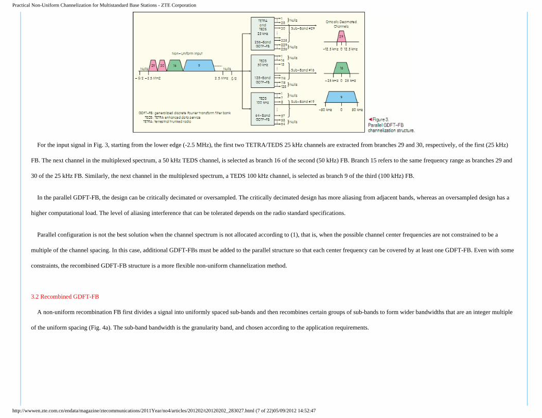
Fig. 3 shows the parallel GDFT-FB for the 5 MHz uplink band of a TETRA/TEDS base station. In this band, there are 200 channels for TETRA V&D and TEDS 25 kHz. For TEDS 50 kHz,
there are 100 channels, and for TEDS 100 kHz, there are 50 channels. DFT modulation is implemented using a power-of-2 FFT for efficiency; thus, the filter bank sub-bands cover a bandwidth
larger than the frequency band containing the information channels. The excess sub-bands outside the 5 MHz bands are permanently null.
http://wwwen.zte.com.cn/endata/magazine/ztecommunications/2011Year/no4/articles/201202/t20120202_283027.html (6 of 22)05/09/2012 14:52:47
Practical Non-Uniform Channelization for Multistandard Base Stations - ZTE Corporation
For the input signal in Fig. 3, starting from the lower edge (-2.5 MHz), the first two TETRA/TEDS 25 kHz channels are extracted from branches 29 and 30, respectively, of the first (25 kHz)
FB. The next channel in the multiplexed spectrum, a 50 kHz TEDS channel, is selected as branch 16 of the second (50 kHz) FB. Branch 15 refers to the same frequency range as branches 29 and
30 of the 25 kHz FB. Similarly, the next channel in the multiplexed spectrum, a TEDS 100 kHz channel, is selected as branch 9 of the third (100 kHz) FB.
In the parallel GDFT-FB, the design can be critically decimated or oversampled. The critically decimated design has more aliasing from adjacent bands, whereas an oversampled design has a
higher computational load. The level of aliasing interference that can be tolerated depends on the radio standard specifications.
Parallel configuration is not the best solution when the channel spectrum is not allocated according to (1), that is, when the possible channel center frequencies are not constrained to be a
multiple of the channel spacing. In this case, additional GDFT-FBs must be added to the parallel structure so that each center frequency can be covered by at least one GDFT-FB. Even with some
constraints, the recombined GDFT-FB structure is a more flexible non-uniform channelization method.
3.2 Recombined GDFT-FB
A non-uniform recombination FB first divides a signal into uniformly spaced sub-bands and then recombines certain groups of sub-bands to form wider bandwidths that are an integer multiple
of the uniform spacing (Fig. 4a). The sub-band bandwidth is the granularity band, and chosen according to the application requirements.
http://wwwen.zte.com.cn/endata/magazine/ztecommunications/2011Year/no4/articles/201202/t20120202_283027.html (7 of 22)05/09/2012 14:52:47
Practical Non-Uniform Channelization for Multistandard Base Stations - ZTE Corporation
Non-uniform, recombined FBs have been proposed in literature on audio and speech processing [16]. In these applications, the FBs are critically decimated, so a perfect reconstruction
algorithm with parameter optimization is needed to cancel the resulting aliasing. However, because of the asymmetric configuration shown in Fig. 1, such an algorithm is not possible.
Oversampling ensures that aliasing in the transition bands of the sub-band bandpass filters is less than that in the critically sampled case. Non-uniform channelization using recombined,
oversampled FBs has been proposed in [4], [17], [18]. Recombination is carried out by the structure shown in Fig. 4(b). A recombined signal, denoted Y k,R (z ), is formed by R contiguous sub-
bands allocated from the k th output of the GDFT-FB onwards:
Therefore, channels are recombined by interpolating each of the R sub-bands by a factor M, frequency shifting by βr to the correct center frequency, and phase correcting by φr in order to
combine these shifted in-phase channels. To minimize amplitude distortion in the recombined channels, an amplitude-complementary prototype filter is required [19].
Because the GDFT-FB outputs are already oversampled by a factor L, the interpolation factor can be M =R/L. Hence, the frequency and phase shifts are, respectively,http://wwwen.zte.com.cn/endata/magazine/ztecommunications/2011Year/no4/articles/201202/t20120202_283027.html (8 of 22)05/09/2012 14:52:47
Practical Non-Uniform Channelization for Multistandard Base Stations - ZTE Corporation
where NM is the order of the interpolation filter, and N is the order of the GDFT-FB prototype filter. To improve the structure in Fig. 4(b), the phase shift, φr , can occur before the
interpolation. This means the phase shift is carried out at a lower sample rate than the anti-image filtering and frequency shift.
The FB is designed to cover an uplink frequency band of 5 MHz and deliver narrowband outputs with bandwidth and channel spacing of 25 kHz. However, the sample rate of the narrowband
channels is twice the channel spacing, that is, K = 2D, because of oversampling. In this particular case, the bandwidths covered are multiples of each other, and the chosen granularity band is 25
kHz. Consequently, the TETRA/TEDS 25 kHz channels may be selected directly, without any recombination, from the appropriate output sub-bands of the GDFT-FB.
For the wider 50 kHz and 100 kHz channels, adjacent output sub-bands of the FB must be recombined using the structure in Fig. 4. TEDS 50 kHz channels are obtained by recombining two
outputs. The channels do not require additional interpolation prior to frequency shifting and combining because of the original oversampling. A TEDS 100 kHz channel is obtained by
interpolating each channel by 2 and then frequency shifting and combining.
3.3 Evaluation of Channelizers
The parallel GDFT-FB and recombined GDFT-FB have the same fundamental channelization capabilities when applied to channels whose bandwidths are related by integer multiples of each
other. In these circumstances, parallel GDFT-FB is best for schemes with few possible channel bandwidths and alignment patterns; for example, TETRA/TEDS only has 3 such bandwidth and
alignment patterns. However, recombination is best for schemes with a greater variety of channel bandwidths and alignment patterns. By decreasing the granularity bandwidth of the recombined
GDFT-FB sub-bands, a wider range of recombined bandwidths is possible. Also, a wider range of center frequencies is possible for applications that do not necessarily conform to (1).
Channelization structures dynamically filter channels with different bandwidths; however, these structures can be differentiated according to computational load, filter design complexity, and
filter implementation complexity.
For complex I and Q input samples, the number of real multiplications and additions for each complex input sample in an analysis or synthesis odd-stacked GDFT-FB are, respectively,
http://wwwen.zte.com.cn/endata/magazine/ztecommunications/2011Year/no4/articles/201202/t20120202_283027.html (9 of 22)05/09/2012 14:52:47
Practical Non-Uniform Channelization for Multistandard Base Stations - ZTE Corporation
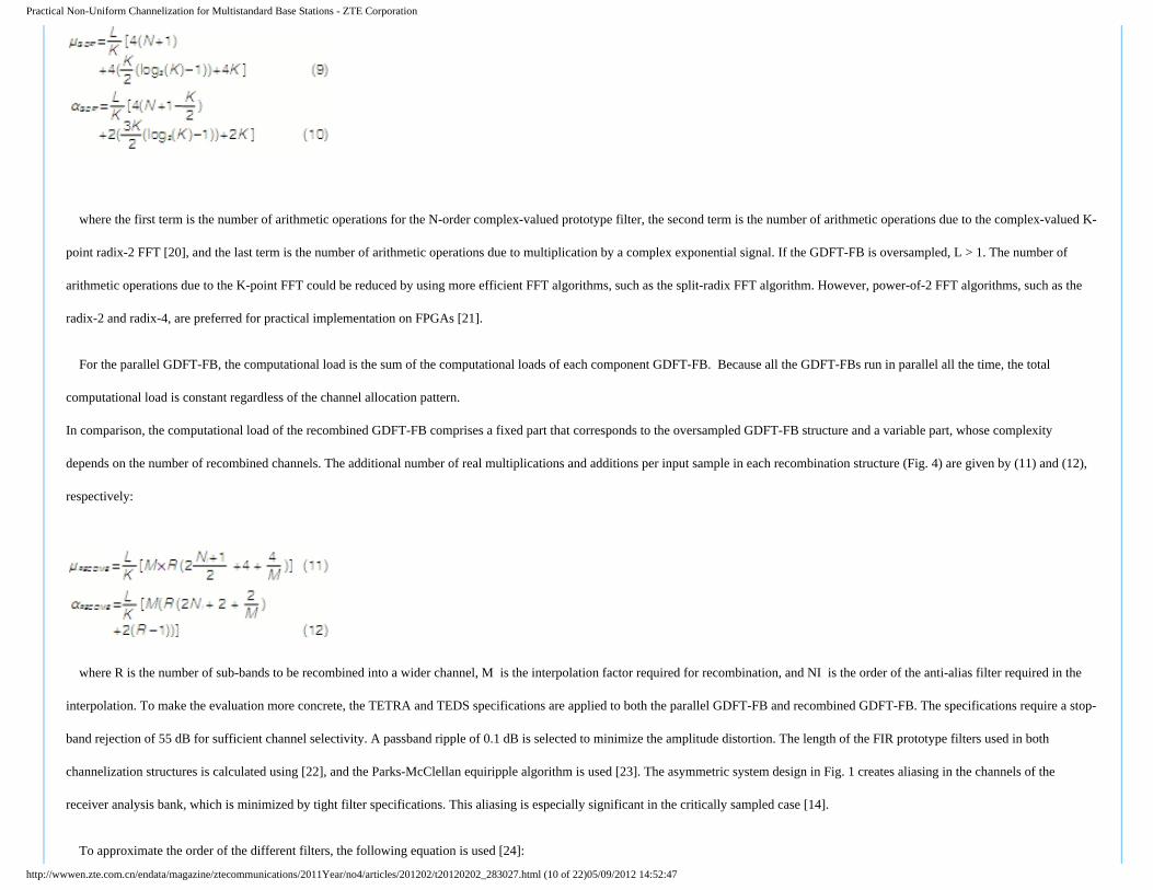
where the first term is the number of arithmetic operations for the N-order complex-valued prototype filter, the second term is the number of arithmetic operations due to the complex-valued K-
point radix-2 FFT [20], and the last term is the number of arithmetic operations due to multiplication by a complex exponential signal. If the GDFT-FB is oversampled, L > 1. The number of
arithmetic operations due to the K-point FFT could be reduced by using more efficient FFT algorithms, such as the split-radix FFT algorithm. However, power-of-2 FFT algorithms, such as the
radix-2 and radix-4, are preferred for practical implementation on FPGAs [21].
For the parallel GDFT-FB, the computational load is the sum of the computational loads of each component GDFT-FB. Because all the GDFT-FBs run in parallel all the time, the total
computational load is constant regardless of the channel allocation pattern.
In comparison, the computational load of the recombined GDFT-FB comprises a fixed part that corresponds to the oversampled GDFT-FB structure and a variable part, whose complexity
depends on the number of recombined channels. The additional number of real multiplications and additions per input sample in each recombination structure (Fig. 4) are given by (11) and (12),
respectively:
where R is the number of sub-bands to be recombined into a wider channel, M is the interpolation factor required for recombination, and NI is the order of the anti-alias filter required in the
interpolation. To make the evaluation more concrete, the TETRA and TEDS specifications are applied to both the parallel GDFT-FB and recombined GDFT-FB. The specifications require a stop-
band rejection of 55 dB for sufficient channel selectivity. A passband ripple of 0.1 dB is selected to minimize the amplitude distortion. The length of the FIR prototype filters used in both
channelization structures is calculated using [22], and the Parks-McClellan equiripple algorithm is used [23]. The asymmetric system design in Fig. 1 creates aliasing in the channels of the
receiver analysis bank, which is minimized by tight filter specifications. This aliasing is especially significant in the critically sampled case [14].
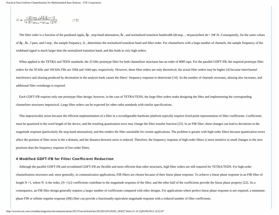
To approximate the order of the different filters, the following equation is used [24]:
http://wwwen.zte.com.cn/endata/magazine/ztecommunications/2011Year/no4/articles/201202/t20120202_283027.html (10 of 22)05/09/2012 14:52:47
Practical Non-Uniform Channelization for Multistandard Base Stations - ZTE Corporation
The filter order is a function of the passband ripple, δp , stop-band attenuation, δs , and normalized transition bandwidth (ω stop , - ω pass)where ω = 2πf /fs .Consequently, for the same values
of δp , δs , f pass, and f stop , the sample frequency, fs , determines the normalized transition band and filter order. For channelizers with a large number of channels, the sample frequency of the
wideband signal is much larger than the normalized transition band, and this leads to very high orders.
When applied to the TETRA and TEDS standards, the 25 kHz prototype filter for both channelizer structures has an order of 8085 taps. For the parallel GDFT-FB, the required prototype filter
orders for the 50 kHz and 100 kHz FBs are 3584 and 1444 taps, respectively. However, these filter orders are only theoretical; the actual filter orders may be higher [4] because interchannel
interference and aliasing produced by decimation in the analysis bank causes the filters’ frequency response to deteriorate [14]. As the number of channels increases, aliasing also increases, and
additional filter overdesign is required.
Each GDFT-FB requires only one prototype filter design; however, in the case of TETRA/TEDS, the large filter orders make designing the filter and implementing the corresponding
channelizer structures impractical. Large filter orders can be expected for other radio standards with similar specifications.
This impracticality arises because the efficient implementation of a filter in a reconfigurable hardware platform typically requires fixed-point representation of filter coefficients. Coefficients
must be quantized to the word length of the device, and the resulting quantization error may change the filter transfer function [25]. In an FIR filter, these changes can lead to deviations in the
magnitude response (particularly the stop-band attenuation), and this renders the filter unsuitable for certain applications. The problem is greater with high-order filters because quantization errors
affect the position of filter zeros in the z-domain, and the distance between zeros is reduced. Therefore, the frequency response of high-order filters is more sensitive to small changes in the zero
positions than the frequency response of low-order filters.
4 Modified GDFT-FB for Filter Coefficient Reduction
Although the parallel GDFT-FB and recombined GDFT-FB are flexible and more efficient than other structures, high filter orders are still required for TETRA/TEDS. For high-order
channelization structures and, more generally, in communication applications, FIR filters are chosen because of their linear phase response. To achieve a linear phase response in an FIR filter of
length N +1, where N is the order, (N +1)/2 coefficients contribute to the magnitude response of the filter, and the other half of the coefficients provide the linear phase property [22]. As a
consequence, an FIR filter design generally requires a larger number of coefficients compared with other designs. For applications where perfect linear phase response is not required, a minimum-
phase FIR or infinite impulse response (IIR) filter can provide a functionally equivalent magnitude response with a reduced number of filter coefficients.
http://wwwen.zte.com.cn/endata/magazine/ztecommunications/2011Year/no4/articles/201202/t20120202_283027.html (11 of 22)05/09/2012 14:52:47
Practical Non-Uniform Channelization for Multistandard Base Stations - ZTE Corporation
When linear phase response is required, multistage filtering [26] is a useful technique that can be applied to FIR filter design to reduce the total number of filter coefficients. Multistage filtering
is most commonly applied to interpolators and decimators that have large sample rate conversion factors. In a multistage filter design, an original filter is factorized into multiple component
filters which, when cascaded, produce the original filter magnitude and phase response. Component filters have more relaxed specifications than the original filter. Therefore, the number of
coefficients in each component filter is smaller (often much smaller) than the original filter. The design of each component filter is also simplified, and the total computational load is often less
than the original filter.
Here, we show that multistage filtering can be extended to modulated FBs and, in particular, to the GDFT-FB. In FB literature, the term multistage typically refers to a structure in which multiple
FB stages are cascaded to form a complete FB [5], [27]. In the approach presented here, the multistage technique is applied to the prototype filter of only one FB.
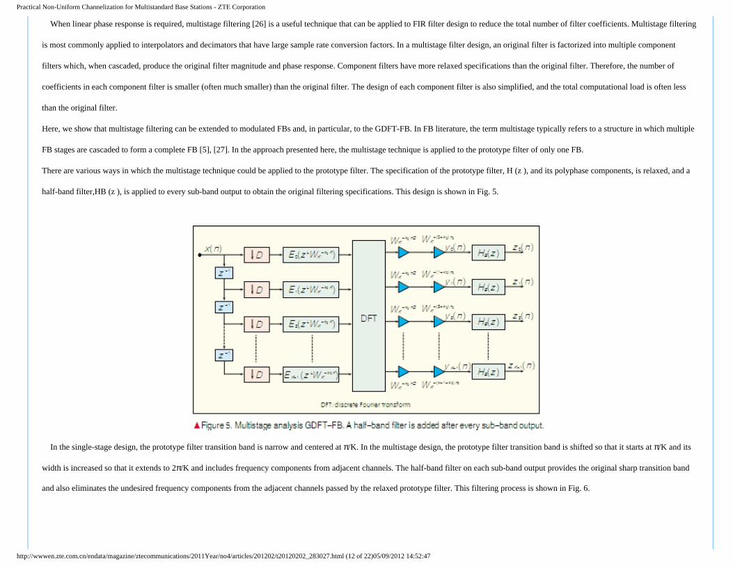
There are various ways in which the multistage technique could be applied to the prototype filter. The specification of the prototype filter, H (z ), and its polyphase components, is relaxed, and a
half-band filter,HB (z ), is applied to every sub-band output to obtain the original filtering specifications. This design is shown in Fig. 5.
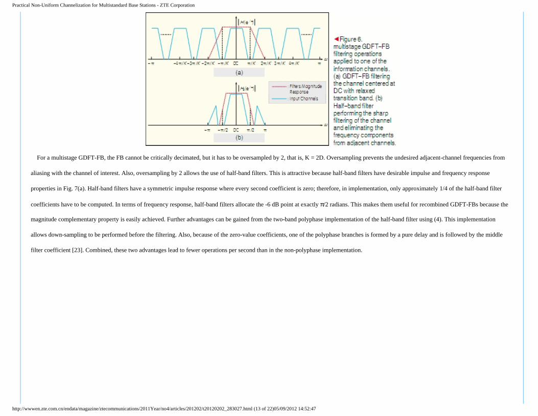
In the single-stage design, the prototype filter transition band is narrow and centered at π/K. In the multistage design, the prototype filter transition band is shifted so that it starts at π/K and its
width is increased so that it extends to 2π/K and includes frequency components from adjacent channels. The half-band filter on each sub-band output provides the original sharp transition band
and also eliminates the undesired frequency components from the adjacent channels passed by the relaxed prototype filter. This filtering process is shown in Fig. 6.
http://wwwen.zte.com.cn/endata/magazine/ztecommunications/2011Year/no4/articles/201202/t20120202_283027.html (12 of 22)05/09/2012 14:52:47
Practical Non-Uniform Channelization for Multistandard Base Stations - ZTE Corporation
For a multistage GDFT-FB, the FB cannot be critically decimated, but it has to be oversampled by 2, that is, K = 2D. Oversampling prevents the undesired adjacent-channel frequencies from
aliasing with the channel of interest. Also, oversampling by 2 allows the use of half-band filters. This is attractive because half-band filters have desirable impulse and frequency response
properties in Fig. 7(a). Half-band filters have a symmetric impulse response where every second coefficient is zero; therefore, in implementation, only approximately 1/4 of the half-band filter
coefficients have to be computed. In terms of frequency response, half-band filters allocate the -6 dB point at exactly π/2 radians. This makes them useful for recombined GDFT-FBs because the
magnitude complementary property is easily achieved. Further advantages can be gained from the two-band polyphase implementation of the half-band filter using (4). This implementation
allows down-sampling to be performed before the filtering. Also, because of the zero-value coefficients, one of the polyphase branches is formed by a pure delay and is followed by the middle
filter coefficient [23]. Combined, these two advantages lead to fewer operations per second than in the non-polyphase implementation.
http://wwwen.zte.com.cn/endata/magazine/ztecommunications/2011Year/no4/articles/201202/t20120202_283027.html (13 of 22)05/09/2012 14:52:47
Practical Non-Uniform Channelization for Multistandard Base Stations - ZTE Corporation
By adding extra filter operations to (9) and (10), the number of real multiplications and additions per complex input for the channelizer is now determined by
where NB is the order of the half-band filters.
This multistage GDFT-FB can replace the single-stage GDFT-FB in the parallel and recombined GDFT-FB channelization methods without any significant changes being made to these
methods. For the recombined GDFT-FB, the phase shift introduced in the recombination structure shown in Fig. 4 and described by (7) is now changed to
which compensates for the changed phase response slope introduced by the half-band filters on each sub-band output.
http://wwwen.zte.com.cn/endata/magazine/ztecommunications/2011Year/no4/articles/201202/t20120202_283027.html (14 of 22)05/09/2012 14:52:47
Practical Non-Uniform Channelization for Multistandard Base Stations - ZTE Corporation
4.1 Channelizers Evaluation Using multistage GDFT-FB
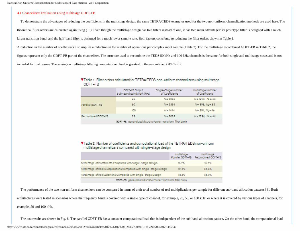
To demonstrate the advantages of reducing the coefficients in the multistage design, the same TETRA/TEDS examples used for the two non-uniform channelization methods are used here. The
theoretical filter orders are calculated again using (13). Even though the multistage design has two filters instead of one, it has two main advantages: its prototype filter is designed with a much
larger transition band, and the half-band filter is designed for a much lower sample rate. Both factors contribute to reducing the filter orders shown in Table 1.
A reduction in the number of coefficients also implies a reduction in the number of operations per complex input sample (Table 2). For the multistage recombined GDFT-FB in Table 2, the
figures represent only the GDFT-FB part of the channelizer. The structure used to recombine the TEDS 50 kHz and 100 kHz channels is the same for both single and multistage cases and is not
included for that reason. The saving on multistage filtering computational load is greatest in the recombined GDFT-FB.
The performance of the two non-uniform channelizers can be compared in terms of their total number of real multiplications per sample for different sub-band allocation patterns [4]. Both
architectures were tested in scenarios where the frequency band is covered with a single type of channel, for example, 25, 50, or 100 kHz, or where it is covered by various types of channels, for
example, 50 and 100 kHz.
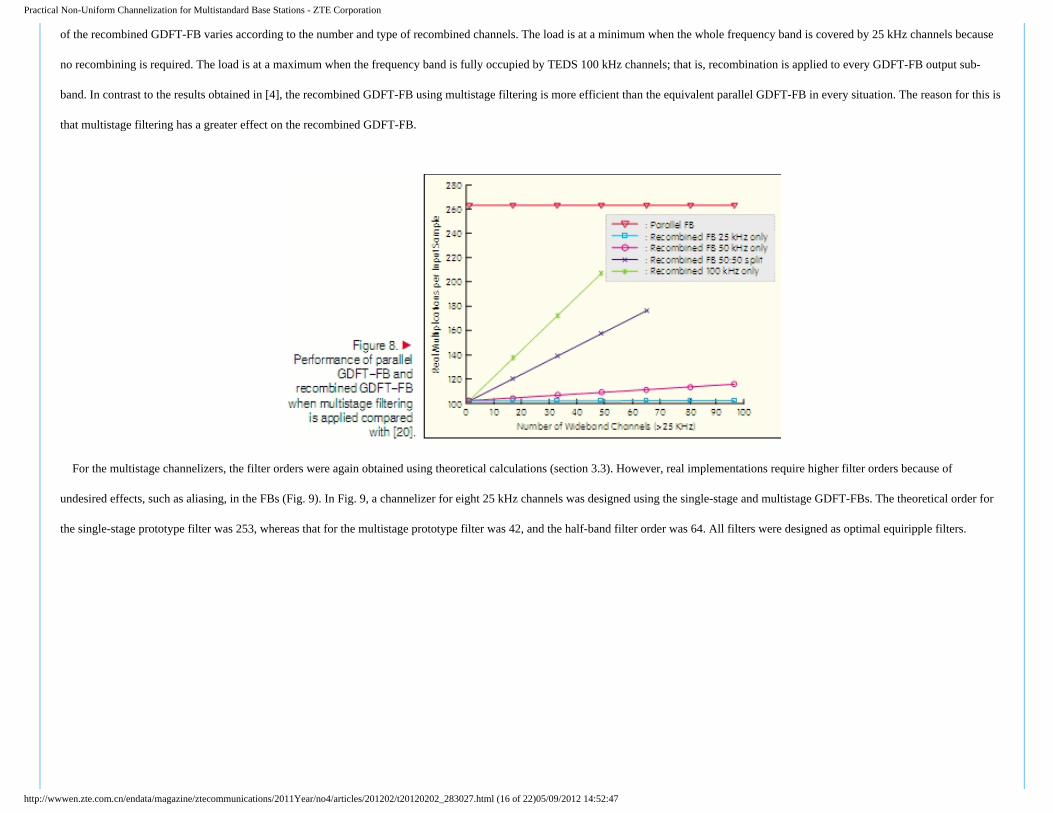
The test results are shown in Fig. 8. The parallel GDFT-FB has a constant computational load that is independent of the sub-band allocation pattern. On the other hand, the computational load
http://wwwen.zte.com.cn/endata/magazine/ztecommunications/2011Year/no4/articles/201202/t20120202_283027.html (15 of 22)05/09/2012 14:52:47
Practical Non-Uniform Channelization for Multistandard Base Stations - ZTE Corporation
of the recombined GDFT-FB varies according to the number and type of recombined channels. The load is at a minimum when the whole frequency band is covered by 25 kHz channels because
no recombining is required. The load is at a maximum when the frequency band is fully occupied by TEDS 100 kHz channels; that is, recombination is applied to every GDFT-FB output sub-
band. In contrast to the results obtained in [4], the recombined GDFT-FB using multistage filtering is more efficient than the equivalent parallel GDFT-FB in every situation. The reason for this is
that multistage filtering has a greater effect on the recombined GDFT-FB.
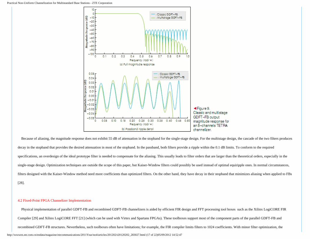
For the multistage channelizers, the filter orders were again obtained using theoretical calculations (section 3.3). However, real implementations require higher filter orders because of
undesired effects, such as aliasing, in the FBs (Fig. 9). In Fig. 9, a channelizer for eight 25 kHz channels was designed using the single-stage and multistage GDFT-FBs. The theoretical order for
the single-stage prototype filter was 253, whereas that for the multistage prototype filter was 42, and the half-band filter order was 64. All filters were designed as optimal equiripple filters.
http://wwwen.zte.com.cn/endata/magazine/ztecommunications/2011Year/no4/articles/201202/t20120202_283027.html (16 of 22)05/09/2012 14:52:47
Practical Non-Uniform Channelization for Multistandard Base Stations - ZTE Corporation
Because of aliasing, the magnitude response does not exhibit 55 dB of attenuation in the stopband for the single-stage design. For the multistage design, the cascade of the two filters produces
decay in the stopband that provides the desired attenuation in most of the stopband. In the passband, both filters provide a ripple within the 0.1 dB limits. To conform to the required
specifications, an overdesign of the ideal prototype filter is needed to compensate for the aliasing. This usually leads to filter orders that are larger than the theoretical orders, especially in the
single-stage design. Optimization techniques are outside the scope of this paper, but Kaiser-Window filters could possibly be used instead of optimal equiripple ones. In normal circumstances,
filters designed with the Kaiser-Window method need more coefficients than optimized filters. On the other hand, they have decay in their stopband that minimizes aliasing when applied to FBs
[28].
4.2 Fixed-Point FPGA Channelizer Implementation
Physical implementation of parallel GDFT-FB and recombined GDFT-FB channelizers is aided by efficient FIR design and FFT processing tool boxes such as the Xilinx LogiCORE FIR
Compiler [29] and Xilinx LogiCORE FFT [21] (which can be used with Virtex and Spartans FPGAs). These toolboxes support most of the component parts of the parallel GDFT-FB and
recombined GDFT-FB structures. Nevertheless, such toolboxes often have limitations; for example, the FIR compiler limits filters to 1024 coefficients. With minor filter optimization, the
http://wwwen.zte.com.cn/endata/magazine/ztecommunications/2011Year/no4/articles/201202/t20120202_283027.html (17 of 22)05/09/2012 14:52:47
Practical Non-Uniform Channelization for Multistandard Base Stations - ZTE Corporation
multistage channelizers could be implemented with these toolboxes. However, the coefficient limitation prevents these toolboxes being used to implement single-stage channelizers because they
require much higher filter orders. Single-stage implementations might still be possible using a customized design, but this implementation requires longer development time.
Mobile communication systems generally use modulation schemes based on real-value in-phase and quadrature (I/Q) signals. For these modulation schemes, complex signal processing is
useful for simplifying the signal operations and notation. Instead of considering the real-value I/Q input signals separately, in complex signal processing the I/Q signals are mapped on a complex
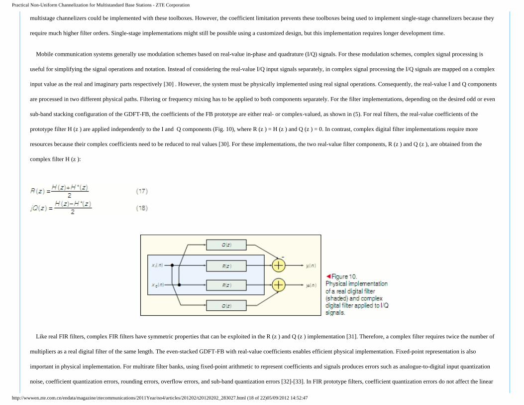
input value as the real and imaginary parts respectively [30] . However, the system must be physically implemented using real signal operations. Consequently, the real-value I and Q components
are processed in two different physical paths. Filtering or frequency mixing has to be applied to both components separately. For the filter implementations, depending on the desired odd or even
sub-band stacking configuration of the GDFT-FB, the coefficients of the FB prototype are either real- or complex-valued, as shown in (5). For real filters, the real-value coefficients of the
prototype filter H (z ) are applied independently to the I and Q components (Fig. 10), where R (z ) = H (z ) and Q (z ) = 0. In contrast, complex digital filter implementations require more
resources because their complex coefficients need to be reduced to real values [30]. For these implementations, the two real-value filter components, R (z ) and Q (z ), are obtained from the
complex filter H (z ):
Like real FIR filters, complex FIR filters have symmetric properties that can be exploited in the R (z ) and Q (z ) implementation [31]. Therefore, a complex filter requires twice the number of
multipliers as a real digital filter of the same length. The even-stacked GDFT-FB with real-value coefficients enables efficient physical implementation. Fixed-point representation is also
important in physical implementation. For multirate filter banks, using fixed-point arithmetic to represent coefficients and signals produces errors such as analogue-to-digital input quantization
noise, coefficient quantization errors, rounding errors, overflow errors, and sub-band quantization errors [32]-[33]. In FIR prototype filters, coefficient quantization errors do not affect the linear
http://wwwen.zte.com.cn/endata/magazine/ztecommunications/2011Year/no4/articles/201202/t20120202_283027.html (18 of 22)05/09/2012 14:52:47
Practical Non-Uniform Channelization for Multistandard Base Stations - ZTE Corporation
phase response characteristics but can affect the magnitude response. By using the multistage design with lower-order filters, the zeros in the z -plane are further apart; therefore, the filter
magnitude response is less
sensitive to quantization error than in filters with higher-order single-stage designs [25].
5 Conclusion
In this paper, we have described the practical implementation of two non-uniform channelization techniques based on GDFT-FBs. These FBs are efficient and flexible, but the use of FIR filters
generally leads to impractically high filter orders. To overcome this problem, a multistage filtering structure was applied to the GDFT-FB to reduce the number of coefficients. Taking this
approach, the number of filter coefficients and operations per input sample are reduced compared with the single-stage design. These reductions make the physical implementation more practical
for fixed-point implementation using existing FPGA tools.
Acknowledgment
The authors wish to thank Jean-Christophe Schiel and Fran?ois Montaigne for their assistance and support. Also the authors extend thanks to the sponsors EADS and IRCSET for the Ph.D.
program.
References
[1] P. Leaves, et al., "Dynamic spectrum allocation in composite reconfigurable wireless networks," Communications Magazine, IEEE, vol. 42, pp. 72-81, 2004.
[2] T. Hentschel, "Channelization for Software Defined Base-Stations," Annales de Telecommunications, May/June 2002.
[3] R. Mahesh, et al., "Filter Bank Channelizers for Multistandard Software Defined Radio Receivers," Journal of Signal Processing Systems, Springer New York, 2008.
[4] A. Palomo Navarro, et al., "Non-Uniform Channelization Methods for Next Generation SDR PMR Base Stations," in IEEE Symposium in Computers and Communications (ISCC 2011),
2011.
[5] C. Zhao, et al., "Reconfigurable Architectures for Low Complexity Software Radio Channelizers using Hybrid Filter Banks," in Communication systems, 2006. ICCS 2006. 10th IEEE
Singapore International Conference on, 2006, pp. 1-5.
[6] P. P. Vaidyanathan, Multirate Systems and Filter Banks: Prentice Hall PTR, 1993.
[7] W. A. Abu-Al-Saud and G. L. Stuber, "Efficient wideband channelizer for software radio systems using modulated PR filterbanks," Signal Processing, IEEE Transactions on, vol. 52, pp.
http://wwwen.zte.com.cn/endata/magazine/ztecommunications/2011Year/no4/articles/201202/t20120202_283027.html (19 of 22)05/09/2012 14:52:47
Practical Non-Uniform Channelization for Multistandard Base Stations - ZTE Corporation
[9] Electromagnetic compatibility and Radio spectrum Matters (ERM); TETRA Enhanced Data Service (TEDS); System reference document, ETSI TR 102 491 V1.2.1, 2006-05.
[10] Planning criteria and coordination of frequencies in the land mobile service in the range 29.7-921 MHz, T/R 25-08, 2008.
[11] A. Eghbali, et al., "A Farrow-structure-based multi-mode transmultiplexer," in Circuits and Systems, 2008. ISCAS 2008. IEEE International Symposium on, 2008, pp. 3114-3117.
[12] A. Eghbali, et al., "Dynamic Frequency-Band Reallocation and Allocation: from Satellite-Based Communication Systems to Cognitive Radios," Journal of Signal Processing Systems, pp. 1-
17, 2009.
[13] R. E. Crochiere and L. R. Rabiner, Multirate Digital Signal Processing: Englewood Cliffs (NJ): Prentice Hall, 1983.
[14] Q.-G. Liu, et al., "Simple design of oversampled uniform DFT filter banks with applications to subband acoustic echo cancellation," Signal Processing, vol. 80, pp. 831-847, 2000.
[15] A. Palomo Navarro, et al., "Overlapped polyphase DFT modulated filter banks applied to TETRA/TEDS SDR base station channelization," presented at the Royal Irish Academy
Communication and Radio Science Colloquium, 2010.
[16] X. M. Xie, et al., "Design of linear-phase recombination nonuniform filter banks," Signal Processing, IEEE Transactions on, vol. 54, pp. 2809-2814, 2006.
[17] F. J. M. G. Harris, R., "A receiver structure that performs simultaneous spectral analysis and time series channelization," in SDR 09 Technical Conference and Product Exposition, 2009.
[18] H. Johansson and P. Lowenborg, "Flexible frequency-band reallocation networks using variable oversampled complex-modulated filter banks," EURASIP J. Appl. Signal Process., vol. 2007,
pp. 143-143, 2007.
[19] S. Radhakrishnan Pillai and G. H. Allen, "Generalized magnitude and power complementary filters," in Acoustics, Speech, and Signal Processing, 1994. ICASSP-94., 1994 IEEE
International Conference on, 1994, pp. III/585-III/588 vol.3.
[20] P. Duhamel and M. Vetterli, "Fast fourier transforms: a tutorial review and a state of the art," vol. 19, ed: Elsevier North-Holland, Inc., 1990, pp. 259-299.
[21] Xilinx, "LogiCORE IP Fast Fourier Transform v7.1 Product Specification," ed, 2010.
[22] T. Saram?ki, "Finite impulse response filter design," in Handbook for Digital Signal Processing, S. K. Mitra and J. F. Kaiser, Eds., ed New York , NY, USA: John Wiley & Sons, 1993, pp.
155-227.
[23] F. J. Harris, Multirate Signal Processing for Communication Systems: Prentice Hall PTR, 2004.
[24] J. Kaiser, "Nonrecursive Digital Filter Design Using the IO-Sinh Window Function," in IEEE International Symposium on Circuits and Systems, 1974.
[25] J. G. Proakis and D. G. Manolakis, Digital signal processing: Principles, Algorithms and Applications: Pearson Prentice Hall, 2007.
[26] L. Milic, Multirate Filtering for Digital Signal Processing: Information Science Reference, 2009.
[27] C. Y. Fung and S. C. Chan, "A multistage filterbank-based channelizer and its multiplier-less realization," in Circuits and Systems, 2002. ISCAS 2002. IEEE International Symposium on,
2002, pp. III-429-III-432 vol.3.
http://wwwen.zte.com.cn/endata/magazine/ztecommunications/2011Year/no4/articles/201202/t20120202_283027.html (20 of 22)05/09/2012 14:52:47
Practical Non-Uniform Channelization for Multistandard Base Stations - ZTE Corporation[28] K. F. C. Yiu, et al., "Multicriteria design of oversampled uniform DFT filter banks," Signal Processing Letters, IEEE, vol. 11, pp. 541-544, 2004.
[30] K. W. Martin, "Complex signal processing is not complex," Circuits and Systems I: Regular Papers, IEEE Transactions on, vol. 51, pp. 1823-1836, 2004.
[31] F. Bruekers, "Symmetry and Efficiency in Complex FIR Filters," Philips Research Laboratories, Eindhoven, 2009.
[32] M. Abo-Zahhad, "Current state and future directions of multirate filter banks and their applications," Digital Signal Processing, vol. 13, pp. 495-518, 2003.
[33] T. Karp and A. Mertins, "Implementation of biorthogonal cosine-modulated filter banks with fixed-point arithmetic," in Circuits and Systems, 2001. ISCAS 2001. The 2001 IEEE
International Symposium on, 2001, pp. 469-472 vol. 2.
Biographies
álvaro Palomo Navarro ([email protected]) received his B.Eng. degree in telecommunications engineering from the Polytechnic University of Madrid (UPM) in 2006. He carried
out his final year project in the Signal Processing Department at BTH, Sweden. Between 2006 and 2007 álvaro worked as a test engineer of GSM intelligent networks. Since 2007 he has been a
Ph.D. candidate at the Callan Institute at NUI Maynooth. His main research interests include multirate digital signal processing, adaptive equalization, software-defined radio and Multistandard
wireless communications systems. He also collaborates with the Electronic Engineering Department as occasional lecturer and tutor.
Rudi Villing ([email protected]), MIEEE, received his B.Eng. degree in electronic engineering from Dublin City University in 1992. He spent the next 10 years working in the
telecommunications software industry and became a specialist in telecommunications management networks (TMN). He worked as a product architect with Euristix Ltd. and Marconi Plc,
creating the architecture for strategic network management technologies before joining the Electronic Engineering Department at NUI Maynooth in 2002. He received his Ph.D. degree from NUI
Maynooth. His research interests include wireless communications and applications and perceptual signal processing.
Ronan J. Farrell ([email protected]) received his B.E. and Ph.D. degrees in electronic engineering from University College Dublin in 1993 and 1998. He is currently a senior
lecturer at the National University of Ireland, Maynooth, and director of the Callan Institute for applied ICT. His research interests include physical layer communication technologies, in
particular, adaptive receivers, Pas, and active antenna arrays. He is currently the strand leader responsible for radio technologies in the SFI-funded Centre for Telecommunications Research.
In related news: ●
TOP• Closehttp://wwwen.zte.com.cn/endata/magazine/ztecommunications/2011Year/no4/articles/201202/t20120202_283027.html (21 of 22)05/09/2012 14:52:47