PRACTICAL SWAY MOTION CONTROL FOR DOUBLE PENDULUM-TYPE OVERHEAD CRANE SYSTEM M. N. A. Zohari, M. Z. Mohd Tumari, M. S. Saealal, K.H. Ghazali and M.S. Ramli Faculty of Electrical and Electronics Engineering Universiti Malaysia Pahang, 26600 Pekan, Pahang, Malaysia Emails: [email protected]Submitted: 8 March 2012 Accepted: May 10, 2012 Published: June 1, 2012 Abstract- The sway motion of crane can be successfully suppressed by properly shaping the reference command. Input shaping is a one type of feed-forward shaping method that is based on linear superposition. In this paper, we present the impact of double pendulum type overhead crane (DPTOC) system on the effectiveness of input shaping. An unshaped bang-bang input force is used to determine the characteristic parameters of the system for design and evaluation of the input shaping control techniques. The input shapers with the derivative effects are designed based on the properties of the system. The response DPTOC system to shaped input is experimentally verified in time and frequency domain. The performance of the input shaper is examined in terms of sway angle reduction and time response specification. Experimental results demonstrate the effectiveness of the proposed approach in reducing the sway motion of crane system. Index terms: Input shaping, double pendulum, and sway motion. INTERNATIONAL JOURNAL ON SMART SENSING AND INTELLIGENT SYSTEMS, VOL. 5, NO. 2, JUNE 2012 362
Transcript
PRACTICAL SWAY MOTION CONTROL FOR DOUBLE
PENDULUM-TYPE OVERHEAD CRANE SYSTEM
M. N. A. Zohari, M. Z. Mohd Tumari, M. S. Saealal, K.H. Ghazali and M.S. Ramli
The sway motion of crane payloads causes safety hazards, time delays and difficulty in
positioning. Much of the previous work on crane control has attempted to address this issue
using techniques based around a single-pendulum model of a crane. Most of the experienced
crane operators can eliminate much of the payload sway by causing an oscillation during
deceleration that cancels the oscillation induced during acceleration if a crane behaves like a
single pendulum. However, certain types of payloads and riggings result in double pendulum
dynamics [1,2]. Under these conditions, the manual method of eliminating sway motion becomes
very difficult, even for skilled operators. To overcome this problem, some researchers have
suggested a feedback control to suppress the double pendulum dynamics [3,4]. However, it is
very challenging due to the difficulty of measuring the payload motion. Since the control of sway
or vibration of a kind of flexible structure required the frequencies information [5, 6], a classical
and robust controller have been proposed in [7] and [8], respectively, to control the first mode of
vibration. However, the results do not directly translated to higher number of vibration mode. As
a consequence, the input shaping techniques is more preferable in this study.
This paper focuses on the application of input shaping schemes to reduce a hook and load
sway motion of double pendulum type overhead crane. Input shaping is a method of command
filtering that allows many oscillatory systems to be moved without inducing residual vibration.
Input shaping is implemented by convolving a series of impulses, known as the input shaper, with
a desired reference command. This produces a command that will drive the system while limiting
residual vibration [9,10]. This process is illustrated in Figure 1 with a smooth initial reference
command. Input shaping is attractive because the scheme only estimates the natural frequencies
and damping ratios of the dominant modes of vibration. Input shaping relies on the superposition
of impulse responses of a second-order system. To design the input shaper, the response of a
second-order harmonic oscillator of frequency, ω, and damping ratio, ζ, to a series of n impulses
is set equal to zero, or a near-zero value. The equation is then solved to determine the impulse
amplitudes, Ai, and time locations, ti, that would produce such a small value of residual vibration.
This low-vibration impulse sequence is then used in the shaping process shown in Figure 1.
Am
pli
tude
Time *
A1
A2
Time
Am
pli
tude
Unshaped Input Input Shaper Shaped input
M. N. A. Zohari, M. Z. Mohd Tumari, M. S. Saealal, K.H. Ghazali and M.S. Ramli, Practical Sway Motion Control for Double Pendulum-type Overhead Crane System
363
Figure 1. Illustration of input shaping technique.
The earliest form of input shaping was developed by Smith. However, his posicast control
method was extremely sensitive to modeling errors [11]. This sensitivity to modeling errors
prohibited the input shaper from practical use on many systems. Singer and Seering were the first
to develop an input-shaping technique robust enough to be used in most practical applications. To
reduce the sensitivity of the input shaper to errors in natural frequency, they set the derivative of
the vibration with respect to the natural frequency to zero at the modeling frequency.
However, the rise-time penalty incurred for the added robustness of this shaper. To solve this
drawback, Singhose and his co-workers [12] have proposed the extra-insensitive (EI) shaper. In
order to increase the robustness of input shapers without adding additional time delays, the
requirement of having exactly zero vibration at the natural frequency need to be relaxed. Instead
of forcing the vibration to exactly zero value, it is allowed to equal some small nonzero value. As
a consequence, the shaper can be more robust without incurring an additional rise-time penalty.
Input shaping was first implemented on a gantry crane at the Savannah River Technology
Center [13]. Fixed-duration (FD) shapers were implemented on this crane, in which the shaper
duration was held fixed while the robustness to modeling errors was maximized. This process
creates a set of shapers for different payload suspension lengths with identical rise times.
Constant rise times are desirable from an operator standpoint, as they do not have to adjust for
variable deceleration times. In previous research, input shaping schemes has been proposed for
sway angle suppression of various types of crane system [14,15,16]. Hong and Hong [17] showed
simulation results for point-to-point motions of container cranes using a deflection-limiting input
shaping technique and nonlinear vibration stabilization control.
This paper presents investigations into the development of input shaping schemes for anti-
swaying control of a double- pendulum-type overhead crane (DPTOC) system. An
experimental rig of DPTOC system is considered in this work. An unshaped bang-bang force
INTERNATIONAL JOURNAL ON SMART SENSING AND INTELLIGENT SYSTEMS, VOL. 5, NO. 2, JUNE 2012
364
input is used to determine the characteristic parameters of the system for design and evaluation
of the input shaping control techniques. The positive zero-sway (PZS), positive zero-sway
derivative (PZSD) and positive zero-sway-derivative-derivative (PZSDD) input shapers are then
designed based on the properties of the system for anti-sway control. Experimental results of
the response of the DPTOC system to the shaped inputs are presented in time and frequency
domains. Performances of the shapers are examined in terms of swing angles reduction
and time response specifications. Finally, a comparative assessment of the input shaping
techniques with different derivative order is presented and discussed.
II. THE DOUBLE PENDULUM-TYPE OVERHEAD CRANE SYSTEM
The DPTOC system with its hook and load considered in this work is shown in Figure 2,
where x is the trolley position, m is the trolley mass, and m1 and m2 are the hook and load mass
respectively. θ1 is the hook swing angle, θ2 is the load swing angle, l1 and l2 are the cable length
of the hook and load, respectively, and F is the trolley drive force. In this simulation, the hook
and load can be considered as point masses.
Figure 2. Description of the DPTOC system.
III. EXPERIMENTAL TEST BED
M. N. A. Zohari, M. Z. Mohd Tumari, M. S. Saealal, K.H. Ghazali and M.S. Ramli, Practical Sway Motion Control for Double Pendulum-type Overhead Crane System
365
In order to verify the effectiveness of the proposed input shaping techniques, experimental
research was conducted on a double pendulum type overhead crane system as shown in Figure 3.
The pendulum system used in this study transmits the rotational power of the motor that is
generated as the motor rotates through the ball screw and the rotation is changed into the straight
line motion through the ball screw. The straight line motion of the ball screw moves the trolley
that is connected to it and the pendulum angle that is connected to the trolley is controlled.
Figure 3. Double pendulum type overhead crane system at Control and Instrumentation Lab,
UMP.
Since the overhead crane system using two pendulums, it requires two encoder sensors to sense
the sway motion at hook and load of the pendulum. The location of the trolley is recognized by
the encoder that is connected to the motor. The detail specification of the lab-scale overhead
crane system is shown in Table 1. The input shaping schemes is designed and implemented using
CEMTool and SIMTool software with the sampling period selected at 1 ms. The encoder
sensor’s signals from the angle and trolley motion are connected to analogue I/O Port of RG-
DSPIO01 with a voltage range of -10V to +10V. The output of the controller is also sending to
the analogue I/O Port of RGDSPIO01 using 25P connector.
INTERNATIONAL JOURNAL ON SMART SENSING AND INTELLIGENT SYSTEMS, VOL. 5, NO. 2, JUNE 2012
366
Table 1: Specifications of double pendulum type overhead crane system
Item Specifications
Mechanical
W x L x H (mm) 1330 x 200 x 250
Length of hook 200mm
Length of load 400mm
Weight of hook 0.5kg
Weight of load 0.2kg
Displacement movement 900mm
Ball screw pitch 12.7mm
Electrical
Motor Output 24V, 60W
Maximum rotation of motor 3800 rpm
Encoder Pulse 4000 pulses
Motor input voltage 0-5V
IV. INPUT SHAPING CONTROL SCHEMES
The design objectives of input shaping are to determine the amplitude and time locations of
the impulses in order to reduce the detrimental effects of system flexibility. These parameters are
obtained from the natural frequencies and damping ratios of the system. This input shaping
design has been motivated by the previous study from the Woodruff School of Mechanical
Engineering, Georgia Institute of Technology [18,19]. They have study the input shaper design to
suppress the multimode vibration from the double pendulum dynamics. The great finding of their
research is the important of the second mode when the mass of the hook is significant when
compared to the mass of the payload. They used the linearized natural frequencies of the double
pendulum dynamics equation from Blevins [20] as a simple platform and verified the input
shaper design to the portable crane system. The outcome of their study has been tabulated in
Figure 4 which is show the variation of low and high frequencies as a function of the mass ratio
and the length of load.
M. N. A. Zohari, M. Z. Mohd Tumari, M. S. Saealal, K.H. Ghazali and M.S. Ramli, Practical Sway Motion Control for Double Pendulum-type Overhead Crane System
367
Figure 4: Variation of low and high frequencies [17].
However, their investigations only limited to two mode of sway frequency only. This study
can be more practical if three modes of sway frequencies are considered to design the input
shapers. Since the ratio of the payload mass to the hook mass is very significant in this study, the
higher mode should be taken into account when designing the input shaper. The corresponding
design relations for achieving a zero residual of the first three modes sway of a system and to
ensure that the shaped command input produces the same rigid body motion as the unshaped
command. Generally, a vibratory system of any order can be modelled as a superposition of
second order systems each with a transfer function
22
2
2)(
sssG (1)
where ω is the natural frequency of the vibratory system and ζ is the damping ratio of the system.
Thus, the response of the system in time domain can be obtained as
INTERNATIONAL JOURNAL ON SMART SENSING AND INTELLIGENT SYSTEMS, VOL. 5, NO. 2, JUNE 2012
368
)(1sinexp1
)( 02)(
2
0 ttA
tytt
(2)
where A and t0 are the amplitude and the time location of the impulse respectively. The response
to a sequence of impulses can be obtained by superposition of the impulse responses. Thus, for N
impulses, with 21 d, the impulse response can be expressed as
tMty dsin)( (3)
where
2
1
2
1
sincos
N
i
ii
N
i
ii BBM ,
)(
2
0exp1
ttii
AB
, idi t
and Ai and ti are the amplitudes and time locations of the impulses.
The residual single mode vibration amplitude of the impulse response is obtained at the time
of the last impulse, tN as
22
21 VVV (4)
where
)cos(exp1
)(
12
1 idtt
N
i
ni tA
V iNn
;
)sin(exp1
)(
12
2 idtt
N
i
ni tA
V iNn
M. N. A. Zohari, M. Z. Mohd Tumari, M. S. Saealal, K.H. Ghazali and M.S. Ramli, Practical Sway Motion Control for Double Pendulum-type Overhead Crane System
369
To achieve zero vibration after the last impulse, it is required that both V1 and V2 in Equation
(4) are independently zero. This is known as the zero residual vibration constraints. In order to
ensure that the shaped command input produces the same rigid body motion as the unshaped
reference command, it is required that the sum of amplitudes of the impulses is unity. This yields
the unity amplitude summation constraint as
N
i
iA1
1 (5)
In order to avoid response delay, time optimality constraint is utilised. The first impulse is
selected at time t1 = 0 and the last impulse must be at the minimum, i.e. min (tN). The robustness
of the input shaper to errors in natural frequencies of the system can be increased by taking the
derivatives of V1 and V2 to zero. Setting the derivatives to zero is equivalent to producing small
changes in vibration corresponding to the frequency changes. The level of robustness can further
be increased by increasing the order of derivatives of V1 and V2 and set them to zero. Thus, the
robustness constraints can be obtained as
01 i
n
i
d
Vd
; 02
in
i
d
Vd
(6)
The positive ZS input shaper, i.e. two-impulse sequence is designed by taking into consideration
the zero residual sway constraints, time optimality constraints and unity magnitude constraints.
Hence, by setting V1 and V2 in Equation (4) to zero,
N
i iA1
1 , t1 = 0 to avoid response delay
and solving yields a two-impulses sequence with parameters as
t1 = 0, t2 = d
,
A1 = K1
1 , A2 = K
K
1 (7)
INTERNATIONAL JOURNAL ON SMART SENSING AND INTELLIGENT SYSTEMS, VOL. 5, NO. 2, JUNE 2012
370
where
21
eK , 21 nd
(n and representing the natural frequency and damping ratio respectively) and tj and Aj are
the time location and amplitude of impulse j respectively. The positive ZS shaper does not
consider the robustness constraints. To increase the robustness of the positive input shaper, the
robustness constraints must be considered in solving for the time locations and amplitudes of the
impulses sequence. The robustness constraints equations can be obtained by setting the
derivatives of V1 and V2 in Equation (4) to zero. By solving the zero-residual sway, robustness,
unity magnitude and time optimality constraints yield a three-impulse sequence known as the
positive ZSD shaper.
t1 = 0, t2 = d
, t3 =
d
2
21
21
1
KKA
,
2221
2
KK
KA
,
2
2
321 KK
KA
(8)
To obtain a positive input shaper with higher level of robustness, another set of constraints
equation, i.e. by setting the second derivatives of V1 and V2 in Equation (4) to zero must be
considered in solving for the amplitudes and time locations of the impulse sequence. Simplifying
22ni dVd , yields
N
i
idtt
ii
n
N
i
idtt
ii
n
tetAd
Vd
tetAd
Vd
iNn
iNn
1
)(2
2
22
1
)(2
2
12
)cos(
)sin(
(9)
M. N. A. Zohari, M. Z. Mohd Tumari, M. S. Saealal, K.H. Ghazali and M.S. Ramli, Practical Sway Motion Control for Double Pendulum-type Overhead Crane System
371
The positive ZSDD input shaper, i.e. four-impulse sequence is obtained by setting Equations (4)
and (9) to zero and solving with the other constraint equations. Hence, a four-impulse sequence
can be obtained with the parameters as
t1 = 0, t2 = d
, t3 =
d
2, t4 =
d
3
321
331
1
KKKA
,
322331
3
KKK
KA
32
2
3331
3
KKK
KA
,
32
3
4331 KKK
KA
(10)
where K as is equation (1).
V. IMPLEMENTATION AND RESULTS
In this investigation, input shaping control schemes are implemented and tested within the
experimental environment of the DPTOC system and the corresponding results are presented.
The bang-bang input force of ±1 N is applied to the trolley of the DPTOC. The bang-bang input
is required to have positive and negative period to allow the DPTOC to, initially, accelerate and
then decelerate and eventually, stop at the target position. For the sway suppression schemes,
positive zero-sway (PZS), positive zero-sway-derivative (PZSD) and positive zero-sway-
derivative-derivative (PZSDD) are designed based on the sway frequencies and damping ratios of
the DPTOC system. The first three modes of sway of the system are considered, as these
dominate the dynamic of the system. The responses of the DPTOC system to the unshaped input
were analyzed in time-domain and frequency domain (spectral density). These results were
considered as the system response to the unshaped input and will be used to evaluate the
performance of the input shaping techniques. The sway frequencies for both hook cable and
load cable were obtained as 0.977 Hz, 1.953 Hz and 2.686 Hz for the first three modes of sway.
INTERNATIONAL JOURNAL ON SMART SENSING AND INTELLIGENT SYSTEMS, VOL. 5, NO. 2, JUNE 2012
372
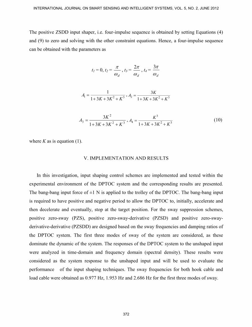
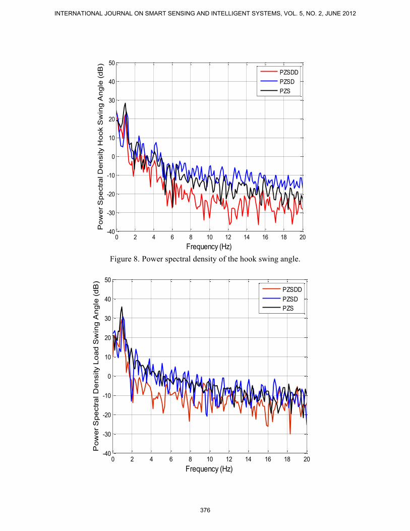
Figures 5-9 show the response of the trolley position, swing angle of hook and load cable and
its power spectral density. Table 2 summarises the levels of sway reduction of the system
responses at the first three modes. Higher levels of sway reduction were obtained using positive
ZSDD shaper as compared using positive ZSD and ZS. However, with positive ZS shaper, the
system response is faster. The corresponding rise time, settling time and overshoot of the trolley
position response for positive shapers is depicted in Table 2. By comparing the results presented
in Table 2, it is noted that the higher performance in the reduction of sway of the system is
achieved using positive ZSDD shaper. This is observed and compared to the positive ZSD and
ZS shaper at the first three modes of sway.
For comparative assessment, the levels of sway reduction of the hoisting angles of the
hook and load cables using positive ZS, ZSD and ZSDD shapers are shown with the bar graphs in
Figure 10 and Figure 11, respectively. The result shows that, highest level of sway reduction is
achieved in control schemes using the positive ZSDD shaper, followed by the positive ZSD and
ZS shaper for all modes of sway, for both of hook and load swing angles. Therefore, it can be
concluded that the positive ZSDD shapers provide better performance in sway reduction as
compared to the positive ZSD and positive ZS shapers in overall. Comparisons of the
specifications of the trolley position response of input shaping control schemes using positive
ZSDD, positive ZSD and ZS are summarized in Figure 12 for the rise and settling times. It is
noted that settling time of the trolley position response by using the positive ZS shaper is faster
than the case using the positive ZSDD shaper. It shows that, in term of settling time, the speed of
the system response can be improved by using positive ZS shapers.
Table 2: Level of sway reduction of the hook and load swing angle of the pendulum and
M. N. A. Zohari, M. Z. Mohd Tumari, M. S. Saealal, K.H. Ghazali and M.S. Ramli, Practical Sway Motion Control for Double Pendulum-type Overhead Crane System
373
Load swing angle, θ2 15.73 42.86 23.55
Figure 5. Response of the trolley position.
0 5 10 15 20 25 30 0
5
10
15
20
25
30
35
40
45
50
55
Time (s)
Tro
lley P
osit
ion
(cm
)
PZS
PZSD
PZSDD
INTERNATIONAL JOURNAL ON SMART SENSING AND INTELLIGENT SYSTEMS, VOL. 5, NO. 2, JUNE 2012
374
Figure 6. Response of the hook swing angle.
Figure 7. Response of the load swing angle.
0 5 10 15 20 25 30-4
-3
-2
-1
0
1
2
3
Time (s)
Ho
ok S
win
g A
ng
le (
deg
)
PZS
PZSD
PZSDD
0 5 10 15 20 25 30 -6
-4
-2
0
2
4
6
Time (s)
Lo
ad
Sw
ing
An
gle
(d
eg
)
PZS
PZSD
PZSDD
M. N. A. Zohari, M. Z. Mohd Tumari, M. S. Saealal, K.H. Ghazali and M.S. Ramli, Practical Sway Motion Control for Double Pendulum-type Overhead Crane System
375
Figure 8. Power spectral density of the hook swing angle.
0 2 4 6 8 10 12 14 16 18 20-40
-30
-20
-10
0
10
20
30
40
50
Frequency (Hz)
Po
we
r S
pe
ctr
al D
en
sity H
oo
k S
win
g A
ng
le (
dB
)
PZSDD
PZSD
PZS
0 2 4 6 8 10 12 14 16 18 20-40
-30
-20
-10
0
10
20
30
40
50
Frequency (Hz)
Po
we
r S
pe
ctr
al D
en
sity L
oa
d S
win
g A
ng
le (
dB
)
PZSDD
PZSD
PZS
INTERNATIONAL JOURNAL ON SMART SENSING AND INTELLIGENT SYSTEMS, VOL. 5, NO. 2, JUNE 2012
376
Figure 9. Power spectral density of the load swing angle.
Figure 10. Level of sway reduction for hook swing angle.
Figure 11. Level of sway reduction for load swing angle.
M. N. A. Zohari, M. Z. Mohd Tumari, M. S. Saealal, K.H. Ghazali and M.S. Ramli, Practical Sway Motion Control for Double Pendulum-type Overhead Crane System
377
Figure 12. Rise and settling times of trolley position with PZS, PZSD and PZSDD shaper.
VI. CONCLUSIONS
The development of input shaping control schemes for anti-sway of a DPTOC system has
been presented. The performances of the control schemes have been evaluated in terms of level
of sway reduction and time response specifications. A comparison of the results has
demonstrated that the positive ZSDD shapers provide higher level of sway reduction as
compared to the cases using positive ZSD and ZS shapers. By using the positive ZS shapers, the
speed of the response is slightly improved in term of settling time at the expenses of decrease
in the level of sway reduction. It is concluded that the experiment results on DPTOC system has
demonstrated the effectiveness and practicality of the proposed approach.
ACKNOWLEDGEMENT
This work was supported by Faculty of Electrical & Electronics Engineering, Universiti
INTERNATIONAL JOURNAL ON SMART SENSING AND INTELLIGENT SYSTEMS, VOL. 5, NO. 2, JUNE 2012
378
Malaysia Pahang, especially Control & Instrumentation (COINS) Research Group under research
grant RDU090350 and RDU100102.
REFERENCES
[1] M. Kenison and W. Singhose, Input Shaper Design for Double Pendulum Planar Gantry
Crane, IEEE Conference on Control Applications, Hawaii, 1999, pp. 539-544.
[2] D. Liu, W. Guo and J. Yi, GA-Based Composite Sliding Mode-Fuzzy Control for Double
Pendulum-Type Overhead Crane, Second International Conference on Fuzzy Systems and
Knowledge Discovery, vol. 3617, 2005, pp. 792-801.
[3] S. Lahres, H. Aschemann, O. Sawodny and E. P. Hofer, Crane automation by decoupling
control of a double pendulum using two translational actuators, Proceedings of the 2000
American Control Conference, vol. 2, 2000, pp. 1052-1056.
[4] S. Tanaka and S. Kouno, Automatic Measurement and Control of the Attitude of Crane
Lifters: Lifter-Attitude Measurement and Control, Control Eng. Practice, vol. 6(9), 1998,
pp. 1099-1107.
[5] K.B. Waghulde and B. Kumar, Vibration analysis of cantilever smart structure by using
piezoelectric smart material, International Journal on Smart Sensing and Intelligent
Systems, vol. 4(3), 2011, pp. 353-375.
[6] W. Li, T.-S. Liu, H.-I. Lin, Y.-J. Tsai, Design of vibration-based miniature generator using
piezoelectric bender, International Journal on Smart Sensing and Intelligent Systems, vol.
3(3), 2010, pp. 550-572.
[7] K. Dhanalakshmi, Aditya Avinash, M. Umapathy, M. Marimuthu, Experimental study on
vibration control of shape memory alloy actuated flexible beam, International Journal on
Smart Sensing and Intelligent Systems, vol. 3(2), 2010, pp. 156-175.
[8] M. Sridevi, P. Madhavasarma, Model identification and Smart structural vibration Control
using H∞ controller, International Journal on Smart Sensing and Intelligent Systems, vol.
3(4), 2010, pp. 655-671.
[9] O. J. M Smith, Feedback Control Systems, McGraw-Hill, New York, 1958, pp. 331–345.
M. N. A. Zohari, M. Z. Mohd Tumari, M. S. Saealal, K.H. Ghazali and M.S. Ramli, Practical Sway Motion Control for Double Pendulum-type Overhead Crane System
379
[10] N. C. Singer, and W. P. Seering, Preshaping command inputs to reduce system vibration,
ASME Journal of Dynamic Systems, Measurement, and Control vol. 112, 1990, pp. 76–82.
[11] G.H. Tallman, and O.J.M. Smith, Analog study of dead-beat posicast control, IRE
Transactions on Automatic Control, vol. 4(1), 1958, pp. 14–21.
[12] W. Singhose, W. Seering, and N. Singer, Residual vibration reduction using vector
diagrams to generate shaped inputs, ASME Journal of Mechanical Design, vol. 116(2),
1994, pp. 654–659.
[13] N. Singer, W. Singhose, and E. Kriikku, An input shaping controller enabling cranes to
move without sway, ANS 7th Topical Meeting on Robotics and Remote Systems, Augusta,
GA, Vol. 1, 1997, pp. 225–231.
[14] M.A. Ahmad, R.M.T. Raja Ismail, M.S. Ramli, N.F. Zakaria, N.M. Abd. Ghani, Robust
Feed-Forward Schemes for Anti-sway Control of Rotary Crane, International Conference
on Computational Intelligence, Modelling and Simulation, Republic Czech, September,
2009, pp. 17 – 22.
[15] M.A. Ahmad, Z. Zulkifely and M.A. Zawawi, Experimental Investigations of Input Shaping
Schemes for Sway Control of a Gantry Crane System, Proceedings of the 2nd
International
Conference on Computer and Network Technology, Bangkok, Thailand, 2010, pp. 483-486.
[16] M.A. Ahmad, R.M.T. Raja Ismail and M.S. Ramli, Input Shaping Techniques for Anti-
sway Control of a 3-D Gantry Crane System, Proceedings of the 2009 IEEE International
Conference on Mechatronics and Automation, Changchun, China, August 9 – 12, 2009, pp.
2876-2881.
[17] K.-T. Hong and K.-S. Hong, Input shaping and VSC of container cranes, IEEE
International Conference on Control Applications, Taipei, Taiwan, September 2–4, 2004,
pp. 1570–1575.
[18] W. Singhose, D. Kim and M. Kenison, Input shaping control of double-pendulum bridge
crane oscillations, ASME Journal of Dynamic Systems, Measurement and Control, vol.
130(3), 2008, p. 034504.
[19] D. Kim and W. Singhose, Performance studies of human operators driving double-
pendulum bridge cranes, Control Eng. Practice, vol. 18(6), 2010, pp. 567-576.
[20] R.D. Blevins, Formulas for natural frequency and mode shape, Van Nostrand Reinhold
Co., New York, NY, 1979.
INTERNATIONAL JOURNAL ON SMART SENSING AND INTELLIGENT SYSTEMS, VOL. 5, NO. 2, JUNE 2012
380
M. N. A. Zohari, M. Z. Mohd Tumari, M. S. Saealal, K.H. Ghazali and M.S. Ramli, Practical Sway Motion Control for Double Pendulum-type Overhead Crane System