PRACTICAL WIRELESS MESH NETWORKS AND THEIR APPLICATIONS by Raluca Mus ˘ aloiu-Elefteri A dissertation submitted to the Johns Hopkins University in conformity with the requirements for the degree of Doctor of Philosophy. Baltimore, Maryland January, 2010 c 2010 Raluca Mus ˘ aloiu-Elefteri All Rights Reserved
Transcript
PRACTICAL WIRELESS MESH NETWORKSAND
THEIR APPLICATIONS
byRaluca Musaloiu-Elefteri
A dissertation submitted to the Johns Hopkins University in conformity with therequirements for the degree of Doctor of Philosophy.
4.1 High-level view of the SMesh architecture. . . . . . . . . . . . . . . . . . . . . . 184.2 View of the SMesh testbed, with the approximative locations of the nodes. A
node’s color indicates the floor on which the node is located. Three of the nodesare Internet gateways. . . . . . . . . . . . . . . . . . . . . . . . . . . . . . . . . . 23
5.1 SMesh routing architecture. . . . . . . . . . . . . . . . . . . . . . . . . . . . . . . 275.2 The routes to a mobile client when redundant multipath routing is used for
mobility support. Client 1 is experiencing a handoff between node 6 and 7, thus,the traffic towards him must be forwarded to both nodes. Router 5 forwardspackets differently depending on the entry point. . . . . . . . . . . . . . . . . . 29
5.3 The actions performed on a packet while it travels through the Linux network-ing stack. The entry point alters the IPID and TOS fields. The rest of therouters tag the packet using the encoded entry point and use this tag to se-lect the appropriate routing table. Before leaving the network interface, thepacket is processed by the MULTIHOP module, which creates additional copiesif necessary. . . . . . . . . . . . . . . . . . . . . . . . . . . . . . . . . . . . . . . . 35
5.4 Changes in the header of a packet that travels between two clients in the mesh,when two Internet gateways are used to shortcut a wireless path. GW=Gateway,IR=Intermediate Router, AP=Access Point. . . . . . . . . . . . . . . . . . . . . . 37
5.5 The routes to a mobile client when unicast forwarding is used. Client 1 isexperiencing a handoff between node 6 and 7, however, packets are deliveredonly to one of them. . . . . . . . . . . . . . . . . . . . . . . . . . . . . . . . . . . . 39
5.6 Generic redundant multipath. The packets between the source and the desti-nation nodes can be routed with different levels of resilience (R). The resiliencelevel is encoded in the header of the packet. . . . . . . . . . . . . . . . . . . . . . 44
5.7 CPU load and loss rates while sending a stream of 1400-byte UDP packets withtransmission rates varying from 100 Kbps to 20 Mbps. The top x-axis showsthe corresponding number of packets/sec. . . . . . . . . . . . . . . . . . . . . . . 47
5.8 CPU load and loss rates while sending an increasing number of full-duplexstreams of 160-byte UDP packets. The top x-axis shows the correspondingnumber of packets/sec. . . . . . . . . . . . . . . . . . . . . . . . . . . . . . . . . . 48
ix
List of Figures List of Figures
5.9 The average TCP throughput between the Internet and a client situated atdifferent hops away from the Internet gateway. The routers are in a simple“line” topology. . . . . . . . . . . . . . . . . . . . . . . . . . . . . . . . . . . . . . . 50
5.10 The average RTT between the Internet and a client situated at different hopsaway from the Internet gateway. The routers are in a simple “line” topology. . . 51
5.11 TCP throughput of a client moving in the network when user space overlayrouting is used. The top line tracks the access point that currently serves theclient. The horizontal lines mark when the number of hops increases by one. . 52
5.12 TCP throughput of a client moving in the network when our proposed routingarchitecture is used. The top line tracks the access point that currently servesthe client. The horizontal lines mark when the number of hops increases by one. 52
5.13 CDF of the one-way latency of the packets delivered to a client moving through-out the mesh. The traffic is a full-duplex 64 Kbps UDP stream. . . . . . . . . . 53
6.1 Overview of the Push-To-Talk system. Mesh users connect to the system usinga SIP-based VoIP application. Phone users connect via the PSTN network to aSIP gateway that routes their calls to the mesh network. . . . . . . . . . . . . . 57
6.2 Push-To-Talk system architecture. . . . . . . . . . . . . . . . . . . . . . . . . . . 596.3 The multicast groups maintained by the system to manage a client (Control)
and its PTT session (CMonitor, Data, Controller). . . . . . . . . . . . . . . . . . 636.4 The sequences of steps performed by the mesh node and the controller node in
order to service user requests. The first part shows how an user requests tospeak, while second part shows how the user is notified when its permission tospeak is granted. . . . . . . . . . . . . . . . . . . . . . . . . . . . . . . . . . . . . 67
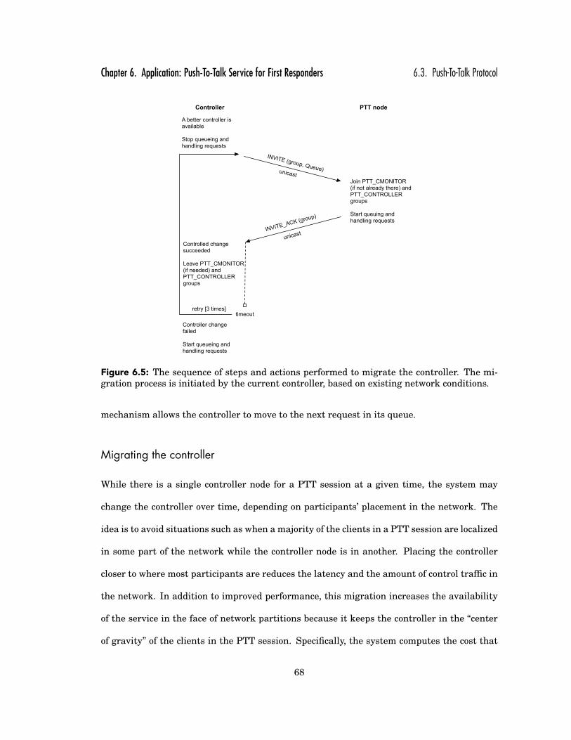
6.5 The sequence of steps and actions performed to migrate the controller. The mi-gration process is initiated by the current controller, based on existing networkconditions. . . . . . . . . . . . . . . . . . . . . . . . . . . . . . . . . . . . . . . . . 68
6.6 Mechanisms that ensure the protocol robustness. The critical components (thecontroller nodes and sending nodes) are continuously monitored and re-instantiatedif the connectivity is lost because of a node crashes or the network partitions. . 70
6.7 The controller is considered lost when its presence messages sent on the mon-itoring group timeout. The node with the lowest IP address becomes the newcontroller of the session. . . . . . . . . . . . . . . . . . . . . . . . . . . . . . . . . 71
6.8 Sequence of steps and actions taken to detect and recover from the situationwhen there are multiple controllers in the network. This happens whenevertwo partitions of the network merge, or because the nodes may temporary havea different view on the network’s topology. . . . . . . . . . . . . . . . . . . . . . . 72
6.9 The sending node is considered lost when its presence messages sent on thePTT CONTROLLER group timeout. In this situation the controller will immedi-ately move to the next request in the pending queue. . . . . . . . . . . . . . . . 73
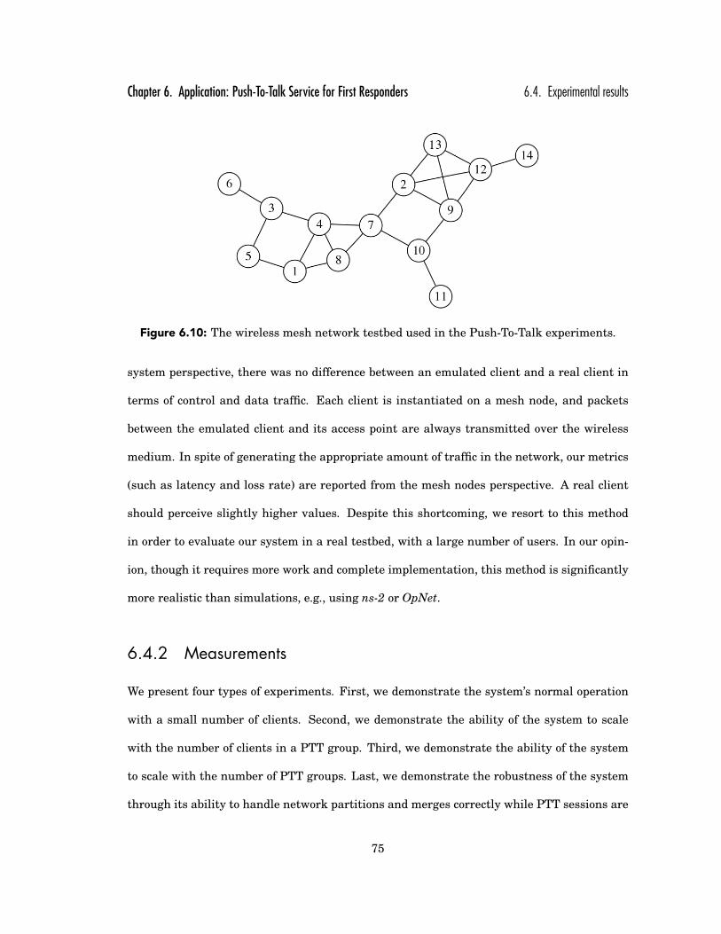
6.10 The wireless mesh network testbed used in the Push-To-Talk experiments. . . 75
x
List of Figures List of Figures
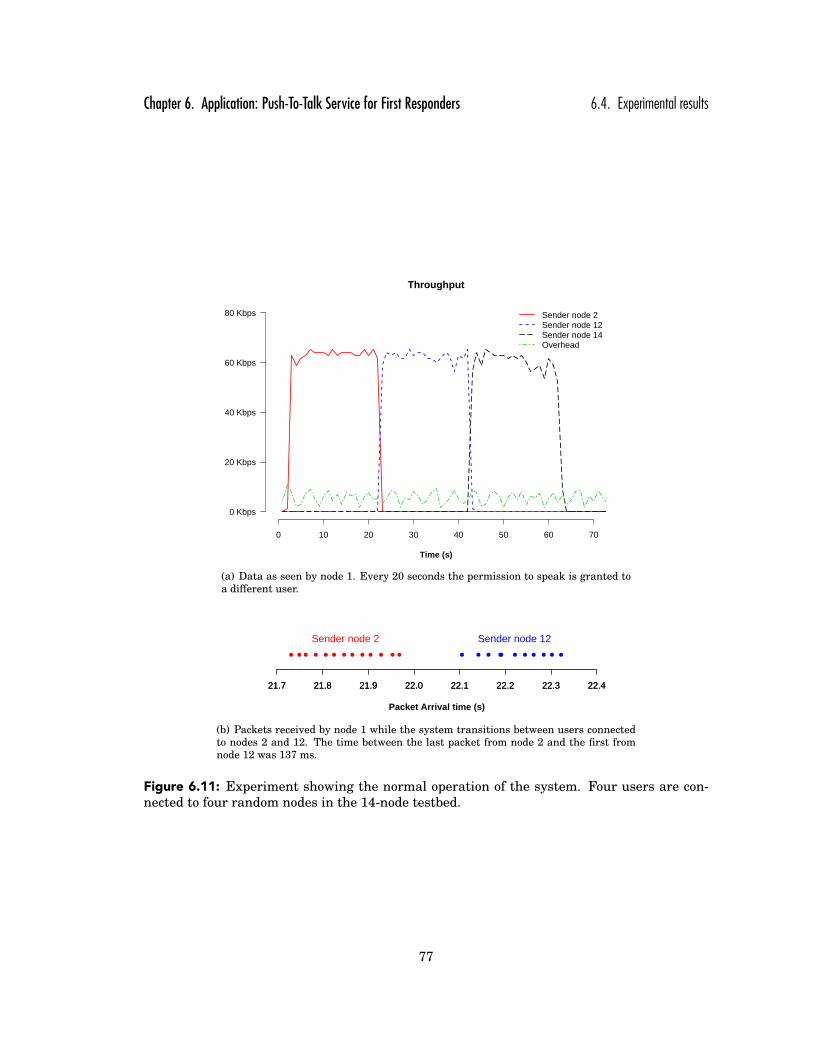
6.11 Experiment showing the normal operation of the system. Four users are con-nected to four random nodes in the 14-node testbed. . . . . . . . . . . . . . . . . 77
6.12 Average latency of the packets received by the nodes when the number of clientsin a PTT group increases from 2 to 42 (3 clients connected to each of the 14access points.) . . . . . . . . . . . . . . . . . . . . . . . . . . . . . . . . . . . . . . 79
6.13 Average loss rate of the packets received by the nodes when the number ofclients in a PTT group increases from 2 to 42 (3 clients connected to each of the14 access points.) . . . . . . . . . . . . . . . . . . . . . . . . . . . . . . . . . . . . 79
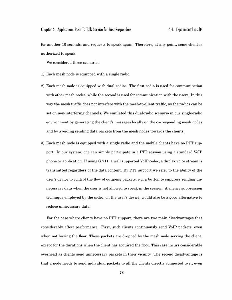
6.14 Boxplots with the average latency of the packets received by the nodes whenthe number of clients in a PTT session increases. Note that the Y-axis hasdifferent ranges in all three scenarios. . . . . . . . . . . . . . . . . . . . . . . . . 81
6.15 Boxplots with the average loss rate of the packets received by the nodes whenthe number of clients in the PTT session increases. Note that the Y-axis hasdifferent ranges in all three scenarios, and its maximum value is 100%. . . . . 82
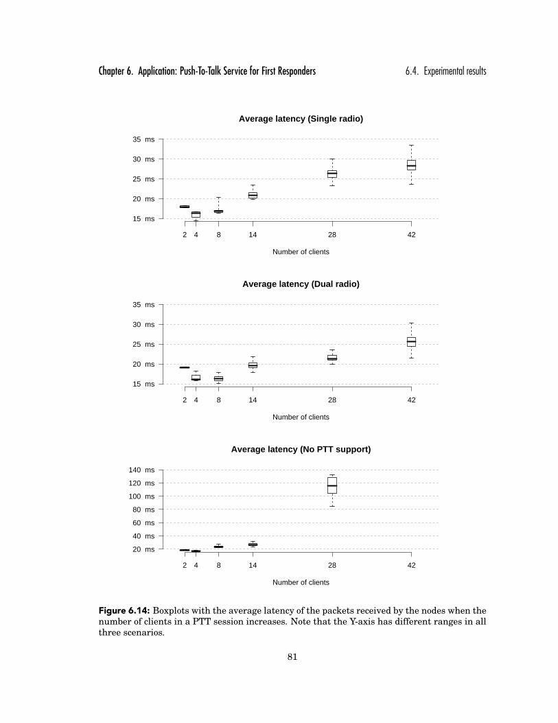
6.16 Average latency of the received packets for all sending nodes, in the single radiosetup. The lighter colors correspond to a lower latency, while the darkest colorcorresponds to a latency of 50 ms or above. The diagonal line is by conventionzero. . . . . . . . . . . . . . . . . . . . . . . . . . . . . . . . . . . . . . . . . . . . . 84
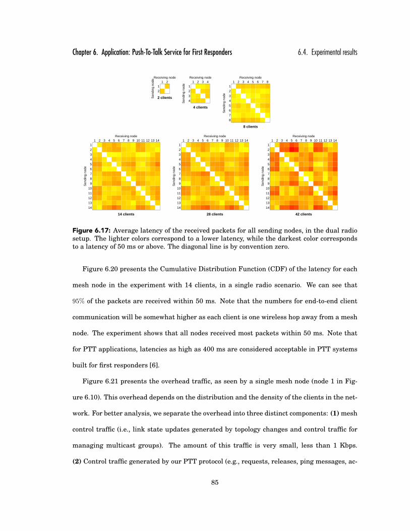
6.17 Average latency of the received packets for all sending nodes, in the dual radiosetup. The lighter colors correspond to a lower latency, while the darkest colorcorresponds to a latency of 50 ms or above. The diagonal line is by conventionzero. . . . . . . . . . . . . . . . . . . . . . . . . . . . . . . . . . . . . . . . . . . . . 85
6.18 Average loss rate of the received packets for all sending nodes, in the singleradio setup. The lighter colors correspond to a lower loss rate, while the dark-est color corresponds to a loss rate of 0.2% or above. The diagonal line is byconvention zero. . . . . . . . . . . . . . . . . . . . . . . . . . . . . . . . . . . . . . 86
6.19 Average loss rate of the received packets for all sending nodes, in the dual radiosetup. The lighter colors correspond to a lower loss rate, while the darkest colorcorresponds to a loss rate of 0.2% or above. The diagonal line is by conventionzero. . . . . . . . . . . . . . . . . . . . . . . . . . . . . . . . . . . . . . . . . . . . . 87
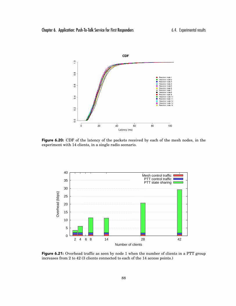
6.20 CDF of the latency of the packets received by each of the mesh nodes, in theexperiment with 14 clients, in a single radio scenario. . . . . . . . . . . . . . . . 88
6.21 Overhead traffic as seen by node 1 when the number of clients in a PTT groupincreases from 2 to 42 (3 clients connected to each of the 14 access points.) . . . 88
6.22 Average latency of the packets received by the nodes when the number of PTTgroups increases from 1 to 20. There are 4 clients in each PTT group. . . . . . . 89
6.23 Average loss rate of the packets received by the nodes when the number of PTTgroups increases from 1 to 20. There are 4 clients in each PTT group. . . . . . . 89
6.24 Boxplots with the average latency of the packets received on each group whenthe number of PTT groups increases from 1 to 20. There are 4 clients in eachPTT group. Note that the Y-axis has different ranges in all four scenarios. . . . 91
xi
List of Figures List of Figures
6.25 Boxplots with the average loss rate of the packets received on each group whenthe number of PTT groups increases from 1 to 20. There are 4 clients in eachPTT group. Note that the Y-axis has different ranges in all four scenarios. . . . 92
6.26 Average latency of the packets on each PTT group. Groups are sorted in theincreasing order of their average latencies. . . . . . . . . . . . . . . . . . . . . . 93
6.27 Traffic before and after a network partition, as seen by client B in the firstpartition and by client D in the second partition. A new controller is generatedin the second partition. . . . . . . . . . . . . . . . . . . . . . . . . . . . . . . . . . 95
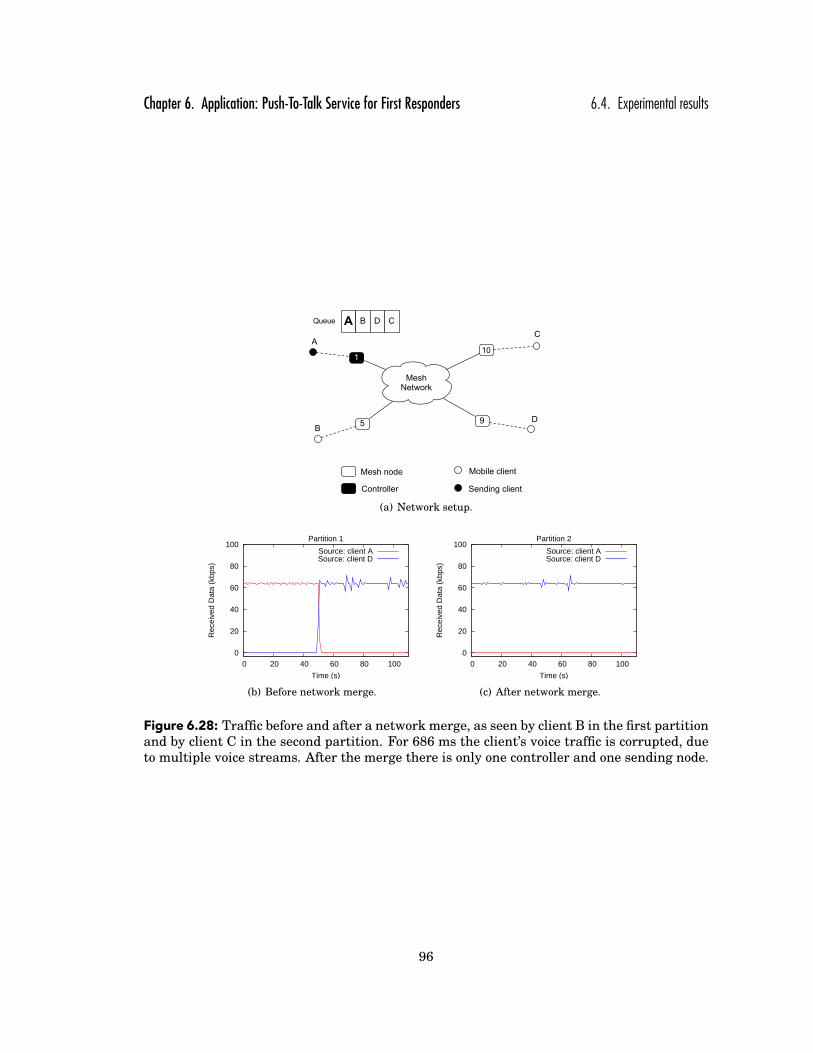
6.28 Traffic before and after a network merge, as seen by client B in the first parti-tion and by client C in the second partition. For 686 ms the client’s voice trafficis corrupted, due to multiple voice streams. After the merge there is only onecontroller and one sending node. . . . . . . . . . . . . . . . . . . . . . . . . . . . 96
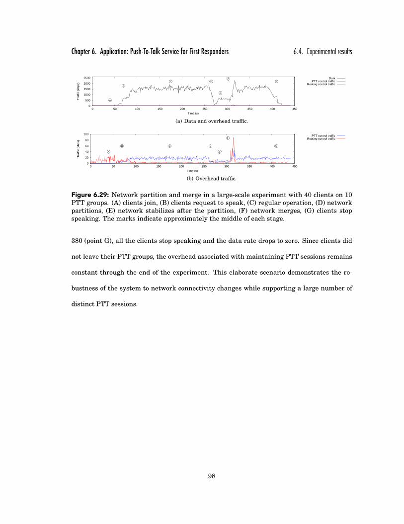
6.29 Network partition and merge in a large-scale experiment with 40 clients on 10PTT groups. (A) clients join, (B) clients request to speak, (C) regular operation,(D) network partitions, (E) network stabilizes after the partition, (F) networkmerges, (G) clients stop speaking. The marks indicate approximately the mid-dle of each stage. . . . . . . . . . . . . . . . . . . . . . . . . . . . . . . . . . . . . . 98
xii
List of Tables
5.1 Number of lost packets on different links when transmitting unicast and mul-ticast packets on 802.11 radios, with and without background traffic. The back-ground traffic consisted of a 1 Mbps stream covering the complete mesh. . . . . 40
as regular access points, their limited CPU capacity can be a bottleneck when they are part
of a mesh infrastructure. This requires routing services that are not natively supported by
current operating systems, limiting the routing mechanisms that can be used to user-level
implementations, which can greatly degrade performance.
Security. Wireless networks’ security, and mesh networks in particular, is challenging for
multiple reasons. First, the way typically a WLAN provides authentication, authorization
and accounting for its users is using a centralized server, such as RADIUS1. This requires
planning, it does not scale well, and it is not suitable for mesh networks that are rapidly
established in an emergency situation. Secondly, mesh nodes cannot be physically secured,
and they can be compromised. In a multi-hop network this is very problematic as it may
disrupt the functionality of the entire network. Fortunately, a great deal of research has been
done on secure routing protocols. However, using such protocols in practice, and in general,
securing a mesh network in the proper way, is a challenging and interesting problem by itself.
For this reason, in this thesis we adopt an open access model, which is suitable and commonly
used in community wireless networks.
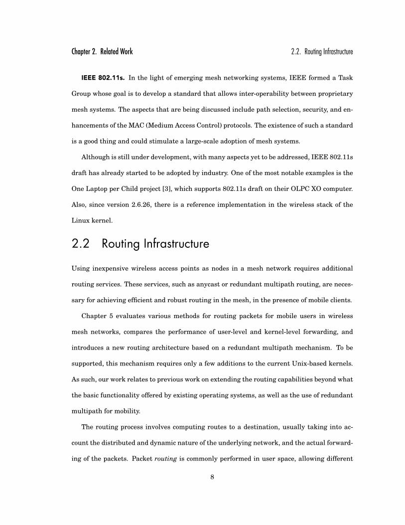
Applications support. Internet access is the most common usage of wireless mesh networks
today. However, by taking advantage of the mesh infrastructure, mesh networks enables
applications beyond the ones typically used in wired and wireless LANs, in areas such as
emergency response, remote monitoring and control, security surveillance. As an example
of such applications, Chapter 6 presents Push-To-Talk, a half-duplex communication service
between multiple participants. Implemented in a mesh network, this system is beneficial as
a robust communication service for first responders.
1Remote Authentication Dial-in User Service.
16
Chapter 4
The SMesh Wireless Mesh Network
The SMesh system is the outcome of several years of research. It went through several stages
of development. This chapter provides a brief overview of the system, setting the stage for
Chapter 5, which describes in detail system’s routing architecture. An in-depth view of the
mobility protocols in SMesh is provided by [18].
4.1 System Overview
The entire handoff and routing logic in SMesh is provided solely by the access points, and
therefore connectivity is attainable for any 802.11 mobile device that supports DHCP, regard-
less of its vendor or architecture. In order to achieve this complete transparency to mobile
clients, our approach uses only standard MAC and IP protocols. The entire mesh network is
seen by the mobile clients as a single, omnipresent access point, giving the mobile clients the
illusion that they are stationary.
4.2 Architecture
The core of the SMesh system consists of two components (Figure 4.1): the Interface with
Mobile Client and the Communication Infrastructure. Together, these components cover the
routing logic, mobility protocols, and client management sub-system. There is also the Push-
17
Chapter 4. The SMesh Wireless Mesh Network 4.2. Architecture
Figure 4.1: High-level view of the SMesh architecture.
To-Talk sub-system, which provides functionality for a half-duplex communication service
between multiple mesh users.
4.2.1 Communication Infrastructure
To allow any node to directly communicate with all the nodes within its range, SMesh uses
802.11 in IBSS mode (ad-hoc). Communication between the mesh nodes is necessary in order
to forward packets over multiple hops, to an Internet gateway.
Multi-hop communication in SMesh is achieved using the Spines messaging system [15]
[8]. This is a convenient tool for unicast, multicast, and anycast communication in an overlay
network. In SMesh we instantiate a Spines daemon in each node in the network and create
an overlay topology that maps to the mesh topology. The Spines daemon discovers nearby
nodes using periodic hello messages, and creates links between nodes when connectivity in
both directions is above a certain threshold. Virtual links are created between the nodes
connected on the wired network.
Spines uses a link-state protocol to disseminate link state updates in the entire network
18
Chapter 4. The SMesh Wireless Mesh Network 4.2. Architecture
(flooding). To minimize the medium usage, these updates are incremental and are sent over
reliable links to a node’s direct neighbors. As the mesh nodes are stationary and mesh users,
which can be highly mobile, are not part of the mesh topology, most of time the protocol will
exchange very little link-state information.
Of particular interest to our system is Spines ability to provide overlay multicast and
anycast communication (multicast and anycast IP addresses are defined in the Spines vir-
tual address space, not in the actual IP address space of the network). We leverage this for
building mobility protocols that provide a seamless handoff for mobiles clients. Traffic on
multicast groups is routed according to multicast trees that are computed in a way similar
to MOSPF [57]. Whenever a node joins or leaves a multicast group the local Spines daemon
updates the rest of the network with a reliable flood. In experiments ran on regular desktop
machines Spines could handle several hundred thousand group members, being limited only
by the available memory to maintain its data structures. [33].
Topology formation. SMesh forms its topology in the following way. Each access point
periodically broadcasts hello messages, allowing the nodes in its coverage area to establish
direct links. All the nodes that are Internet gateways are connected with virtual links over
the wired infrastructure in a fully connected graph. This is achieved using an overlay multi-
cast group, called Internet Gateway Multicast Group (IGMG). An Internet gateway joins this
group and broadcasts its IP address, allowing other Internet gateways to connect.
Routing metric. SMesh topology is hybrid, including both wired and wireless links. Each
link has an actual cost (which can be latency for wired links or ETX [32] for wireless links)
that is adjusted in order to give preference to wired links when computing the cost of a path.
We do this in order to reduce the usage of wireless medium, and also because wired links are
much more reliable and have a higher bandwidth than wireless links. Therefore, even within
the mesh, packets between two source and destination nodes might be routed via hybrid
19
Chapter 4. The SMesh Wireless Mesh Network 4.2. Architecture
paths, by short-cutting long wireless paths with Internet gateways. [18] explains in detail
how this metric is computed.
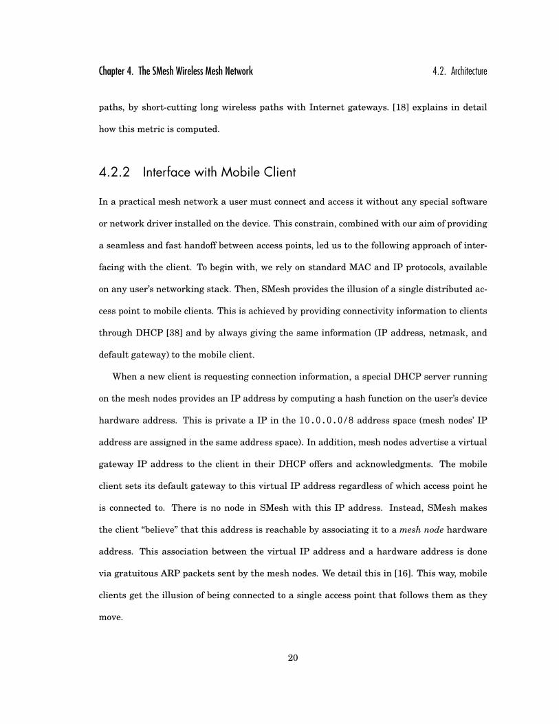
4.2.2 Interface with Mobile Client
In a practical mesh network a user must connect and access it without any special software
or network driver installed on the device. This constrain, combined with our aim of providing
a seamless and fast handoff between access points, led us to the following approach of inter-
facing with the client. To begin with, we rely on standard MAC and IP protocols, available
on any user’s networking stack. Then, SMesh provides the illusion of a single distributed ac-
cess point to mobile clients. This is achieved by providing connectivity information to clients
through DHCP [38] and by always giving the same information (IP address, netmask, and
default gateway) to the mobile client.
When a new client is requesting connection information, a special DHCP server running
on the mesh nodes provides an IP address by computing a hash function on the user’s device
hardware address. This is private a IP in the 10.0.0.0/8 address space (mesh nodes’ IP
address are assigned in the same address space). In addition, mesh nodes advertise a virtual
gateway IP address to the client in their DHCP offers and acknowledgments. The mobile
client sets its default gateway to this virtual IP address regardless of which access point he
is connected to. There is no node in SMesh with this IP address. Instead, SMesh makes
the client “believe” that this address is reachable by associating it to a mesh node hardware
address. This association between the virtual IP address and a hardware address is done
via gratuitous ARP packets sent by the mesh nodes. We detail this in [16]. This way, mobile
clients get the illusion of being connected to a single access point that follows them as they
move.
20
Chapter 4. The SMesh Wireless Mesh Network 4.3. Client Management
4.3 Client Management
In SMesh, two multicast groups are associated with each mobile client.
Client Control Group. An access point in the vicinity of a client joins this multicast group
to coordinate with other mesh nodes in the client’s vicinity. This coordination is necessary for
sharing information required by the handoff protocols. Specifically, each node tracks its own
connection with the client, computes a link metric (using ARP packets sent every 4 seconds
and also packet RSSI1 and retransmit flag, if frame’s full 802.11 header is available), and
advertises the information periodically on this multicast group.
Client Data Group. This multicast group is used to deliver actual data packets to the
client. A mesh node joins the client Data Group if it believes it has the best connectivity with
the client based on the link quality metrics it receives from other nodes.
4.4 Mobility Support
The Client Control Group and Client Data Group provide the basic mechanisms for achieving
a fast intra-domain handoff. In contrast to the roaming mechanisms employed by 802.11
devices2, in SMesh the handoff is controlled from the mesh infrastructure and it relies on
sending data through multiple paths to the mobile client while it transitions from one access
point to another. The access points continuously monitor the connectivity quality of any client
in their vicinity and efficiently share this information with other access points in the vicinity
of that client to coordinate which of them should serve the client. During a handoff, multiple
access points may believe they have the best connectivity with the mobile client, and data
packets to the client will be duplicated by the system in the client’s vicinity. Using multiple
access points during the handoff minimizes the packet loss, allowing real-time applications1Received Signal Strength Indicator.2IEEE 802.11 standard does not specify a roaming mechanism, which led to various (and proprietary) techniques
being employed by the manufactures.
21
Chapter 4. The SMesh Wireless Mesh Network 4.5. SMesh Testbed
such as VoIP. During stable connectivity times the mobile clients are handled by a single
access point. Our protocol guarantees that, at all times, there is at least one member in the
Data Group of each client, such that the client will be served by at least one mesh node [18].
A fast inter-domain handoff is achieved by using multicast groups through the wired net-
work to coordinate decisions and seamlessly transfer connections between Internet gateways
as mobile clients move between access points. The idea is to make new connections always
use the closest Internet gateway at the time of their creation, while existing connections are
forwarded through the wired infrastructure to the Internet gateway where they were orig-
inally initiated. In this way the data is routed optimally to the closest Internet gateway,
without breaking existing connections (as clients are in a private address space, a NAT op-
eration is performed at each Internet gateway). We treat UDP and TCP traffic separately.
As opposed to the intra-domain handoff protocol, the coordination now is between the In-
ternet connected nodes, and is performed over the wired links. [17] explains in detail how
is the routing agreement between Internet gateways reached and how are the connections
transferred to the appropriate nodes.
While duplicating packets and tightly coordinating access points in a client’s vicinity may
seem to incur high overhead, we quantified the overhead and demonstrated it is negligible
compared to data traffic [18].
4.5 SMesh Testbed
Because of the difficulty of conducting experiments on real-world wireless networks, very of-
ten wireless research relies on simulations to evaluate various protocols. While simulations
play a very important role in testing network protocols, most of these simulations are based
on simplifying assumptions. Kotz et al. summarize in [51] the most important “mistaken ax-
ioms” that make wireless simulations unrealistic: “The world is flat.”, “A radio’s transmission
22
Chapter 4. The SMesh Wireless Mesh Network 4.5. SMesh Testbed
Figure 4.2: View of the SMesh testbed, with the approximative locations of the nodes. Anode’s color indicates the floor on which the node is located. Three of the nodes are Internetgateways.
area is circular.”, “All radios have equal range.”, “If I can hear you, you can hear me (symme-
try).”, “If I can hear you at all, I can hear you perfectly.”, “Signal strength is a simple function
of distance”. While efforts have been made to build more realistic simulation tools (e.g., ns-2,
OpNet), real radios and wireless environments are very complex and remain hard to model.
From the very beginning we aimed at building a real system, and understand the practical
problems that such a system experiences. This resulted in a 18-node testbed deployed over
three buildings at Johns Hopkins University, Homewood campus.
In terms of hardware we used off-the-shelf Linksys WRT54G wireless routers. They are
equipped with 802.11b/g Broadcom BCM947XX radios, omnidirectional antennas, 16 MB
RAM, 4 MB flash memory, 200 Mhz CPU speed. Our choice of the router was motivated
by its low cost and because it provides a simple Linux environment. We re-flashed each
router with the open source OpenWrt firmware [4], and used a MIPS cross-compiler to build
our system, written in C.
Nodes’ locations slightly changed over the years. Figure 4.2 shows a map with their ap-
proximative locations, in the most current configuration. Three of these nodes are Internet
23
Chapter 4. The SMesh Wireless Mesh Network 4.5. SMesh Testbed
gateways.
Our efforts of deploying and maintaining a real-world testbed payed off, as we gained a
lot of insight on the problems that wireless mesh networks encounter in practice.
24
Chapter 5
Routing Architecture
Low cost wireless routers are revolutionizing the way we connect to the Internet, becoming
very popular both because of the easiness to deploy, and because of the freedom in the abil-
ity to connect from everywhere they provide. These routers are a revolution from another,
less known perspective: They are very cheap, albeit quite limited, Linux boxes (around $50
a piece). These attributes make them very attractive and convenient for developers to imple-
ment their own applications.
In a mesh network, as opposed to a network of independent access points, a wireless
router must participate in a hybrid wireless-wired, multi-hop, routing mechanism to allow
Internet access from any point in the mesh. In addition, special mechanisms are required
to allow users to seamlessly roam in the network. These kind of routing services must be
built using the native routing capabilities offered by router’s existing operating systems. To
extend routing capabilities without requiring special operating system support, developers
often resort to user-level overlay routing systems, such as the ones overviewed in Chapter 2.
The limitation of resources (in terms of processing power) of a mesh node that uses such user-
level systems impacts the performance, in terms of throughput, of the routing mechanisms
employed in the mesh.
SMesh routing architecture captures the flexibility of user-level overlay systems without
25
Chapter 5. Routing Architecture 5.1. Design
the performance degradation associated with using such systems on resource-constraint de-
vices. This chapter first describes our high-throughput routing architecture, followed by the
key elements that facilitated the implementation of this architecture in Linux, and it ends
with the evaluation of the system using 17 nodes from our testbed.
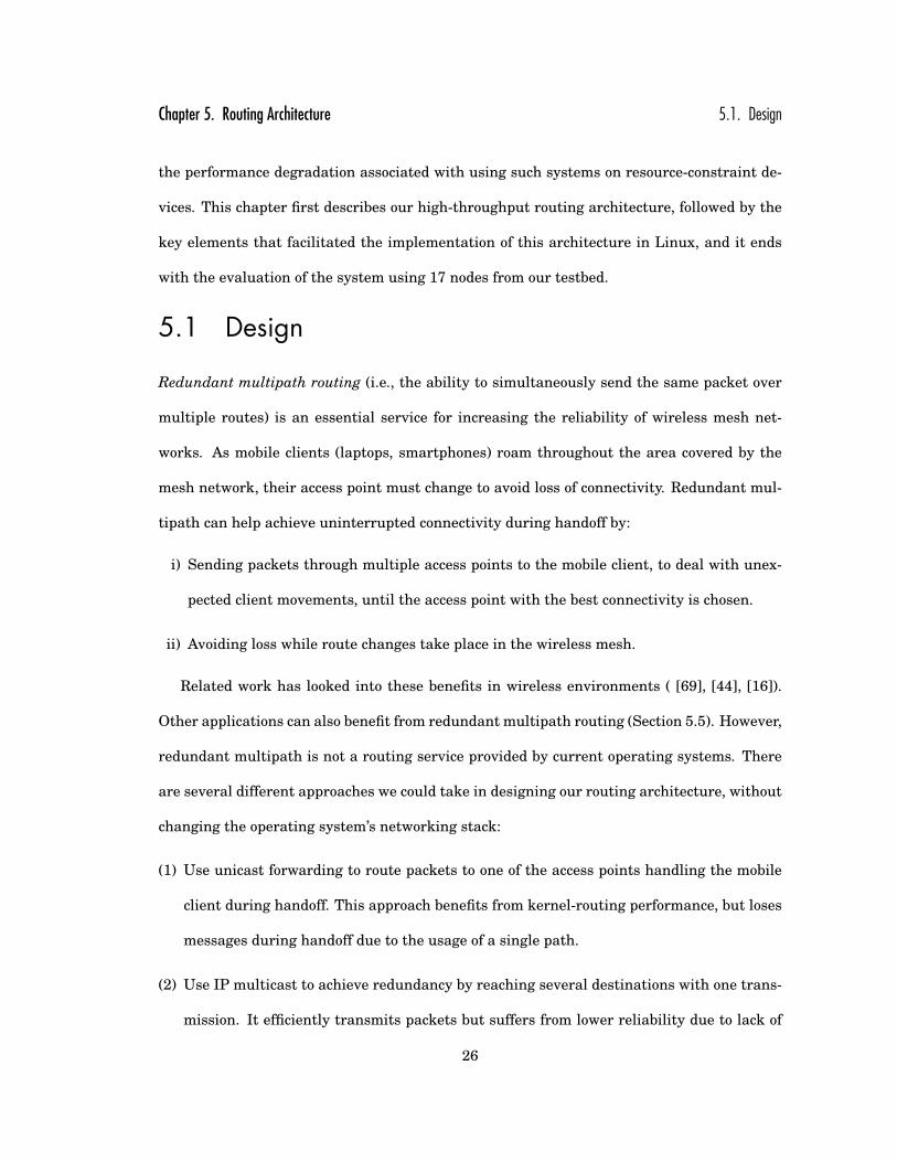
5.1 Design
Redundant multipath routing (i.e., the ability to simultaneously send the same packet over
multiple routes) is an essential service for increasing the reliability of wireless mesh net-
works. As mobile clients (laptops, smartphones) roam throughout the area covered by the
mesh network, their access point must change to avoid loss of connectivity. Redundant mul-
tipath can help achieve uninterrupted connectivity during handoff by:
i) Sending packets through multiple access points to the mobile client, to deal with unex-
pected client movements, until the access point with the best connectivity is chosen.
ii) Avoiding loss while route changes take place in the wireless mesh.
Related work has looked into these benefits in wireless environments ( [69], [44], [16]).
Other applications can also benefit from redundant multipath routing (Section 5.5). However,
redundant multipath is not a routing service provided by current operating systems. There
are several different approaches we could take in designing our routing architecture, without
changing the operating system’s networking stack:
(1) Use unicast forwarding to route packets to one of the access points handling the mobile
client during handoff. This approach benefits from kernel-routing performance, but loses
messages during handoff due to the usage of a single path.
(2) Use IP multicast to achieve redundancy by reaching several destinations with one trans-
mission. It efficiently transmits packets but suffers from lower reliability due to lack of
26
Chapter 5. Routing Architecture 5.1. Design
Figure 5.1: SMesh routing architecture.
802.11 link-layer retransmissions.
(3) Use IP multicast with unicast tunnels on each hop to take advantage of wireless link-
layer retransmission. However, this approach incurs additional space and processing
overhead on each node.
(4) Use user-level overlay routing to provide redundant multipath by routing packets through
user space, at the expense of higher CPU utilization.
Each of these alternatives is described in Section 5.4 and a discussion of the tradeoffs
between them is included in Section 5.4.1.
We adopted a hybrid design, where packet routing is managed in user space but packet
forwarding is efficiently performed at the kernel level. Figure 5.1 gives a high level view of
our routing architecture. There are two main types of communication in mesh networks: be-
tween the client and the Internet, and between clients connected to the mesh (peer-to-peer).
27
Chapter 5. Routing Architecture 5.1. Design
We direct the packets destined to the Internet to the closest Internet gateway. This is accom-
plished by routing packets using an anycast group in which all the Internet gateways join.
The membership of this group is conveniently maintained in user-space and is translated
into a unicast routing table at the kernel level.
On the other hand, traffic directed to the mobile client requires multipath communication,
which cannot be translated directly into a unicast routing table in the kernel.
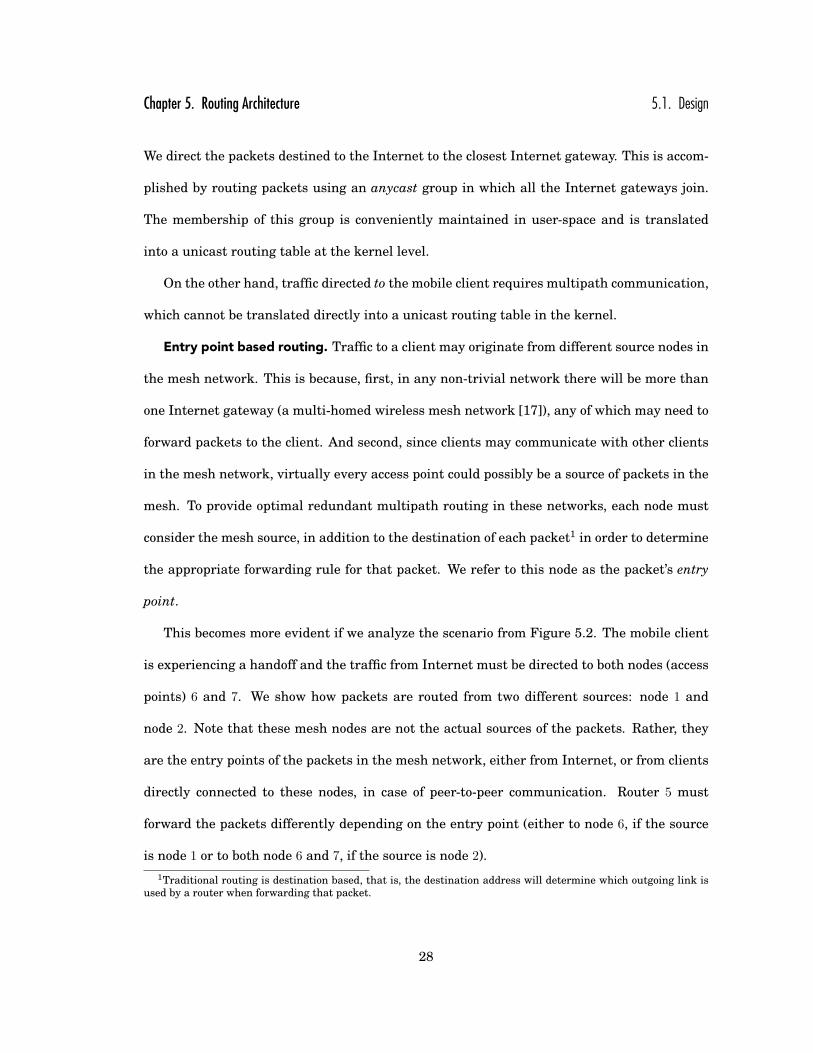
Entry point based routing. Traffic to a client may originate from different source nodes in
the mesh network. This is because, first, in any non-trivial network there will be more than
one Internet gateway (a multi-homed wireless mesh network [17]), any of which may need to
forward packets to the client. And second, since clients may communicate with other clients
in the mesh network, virtually every access point could possibly be a source of packets in the
mesh. To provide optimal redundant multipath routing in these networks, each node must
consider the mesh source, in addition to the destination of each packet1 in order to determine
the appropriate forwarding rule for that packet. We refer to this node as the packet’s entry
point.
This becomes more evident if we analyze the scenario from Figure 5.2. The mobile client
is experiencing a handoff and the traffic from Internet must be directed to both nodes (access
points) 6 and 7. We show how packets are routed from two different sources: node 1 and
node 2. Note that these mesh nodes are not the actual sources of the packets. Rather, they
are the entry points of the packets in the mesh network, either from Internet, or from clients
directly connected to these nodes, in case of peer-to-peer communication. Router 5 must
forward the packets differently depending on the entry point (either to node 6, if the source
is node 1 or to both node 6 and 7, if the source is node 2).1Traditional routing is destination based, that is, the destination address will determine which outgoing link is
used by a router when forwarding that packet.
28
Chapter 5. Routing Architecture 5.1. Design
1 2
6
5
3
4
7
Node 5 routing rules
Source Destination Next−Hop(s)
Node 1
Node 2
Client 1
...
Client 1
....
6
...
6, 7
...
Client 1
Figure 5.2: The routes to a mobile client when redundant multipath routing is used for mobil-ity support. Client 1 is experiencing a handoff between node 6 and 7, thus, the traffic towardshim must be forwarded to both nodes. Router 5 forwards packets differently depending onthe entry point.
Therefore, during the routing process, a mesh node must decide what are the next hops
for a packet based on the mesh entry point as well as the destination address of the packet.
However, the entry point cannot be determined by just looking at the packet destined to the
client (the source address in the IP header is not the address of the mesh entry point, but
the actual address of the sender, which can be another mesh client or an Internet address).
One solution to keep track of the entry point is to tunnel each packet from the entry point in
the mesh to the mobile client. However, to maintain client access transparency, we need to
instruct the kernel to remove the tunnel in the last hop, right before sending the packet to
the client. That requires new kernel functionality. Otherwise, the mobile client may discard
these packets. Another, less obvious approach, is to encode the mesh entry point in some of
the existing space in the IP header of the packet. Specifically, we encode the IP address of the
entry point into the identification field from the packet’s IP header (also referred to as IPID).
This is a 16-bit field used to identify the fragments of the IP datagrams. Together with the
offset field, it is used by the IP layer to reassemble the fragmented datagrams. We discuss
29
Chapter 5. Routing Architecture 5.1. Design
the implications of using this field, in the presence of fragmentation, in Section 5.3.2.
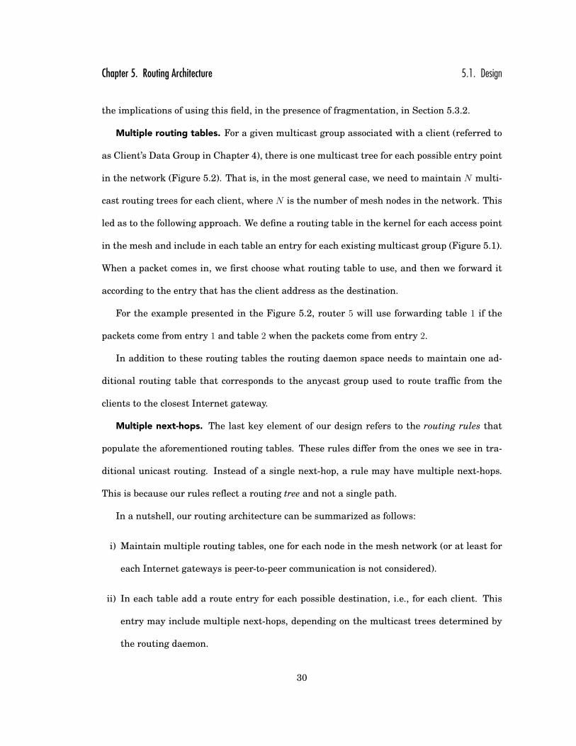
Multiple routing tables. For a given multicast group associated with a client (referred to
as Client’s Data Group in Chapter 4), there is one multicast tree for each possible entry point
in the network (Figure 5.2). That is, in the most general case, we need to maintain N multi-
cast routing trees for each client, where N is the number of mesh nodes in the network. This
led as to the following approach. We define a routing table in the kernel for each access point
in the mesh and include in each table an entry for each existing multicast group (Figure 5.1).
When a packet comes in, we first choose what routing table to use, and then we forward it
according to the entry that has the client address as the destination.
For the example presented in the Figure 5.2, router 5 will use forwarding table 1 if the
packets come from entry 1 and table 2 when the packets come from entry 2.
In addition to these routing tables the routing daemon space needs to maintain one ad-
ditional routing table that corresponds to the anycast group used to route traffic from the
clients to the closest Internet gateway.
Multiple next-hops. The last key element of our design refers to the routing rules that
populate the aforementioned routing tables. These rules differ from the ones we see in tra-
ditional unicast routing. Instead of a single next-hop, a rule may have multiple next-hops.
This is because our rules reflect a routing tree and not a single path.
In a nutshell, our routing architecture can be summarized as follows:
i) Maintain multiple routing tables, one for each node in the mesh network (or at least for
each Internet gateways is peer-to-peer communication is not considered).
ii) In each table add a route entry for each possible destination, i.e., for each client. This
entry may include multiple next-hops, depending on the multicast trees determined by
Figure 5.3: The actions performed on a packet while it travels through the Linux networkingstack. The entry point alters the IPID and TOS fields. The rest of the routers tag the packetusing the encoded entry point and use this tag to select the appropriate routing table. Be-fore leaving the network interface, the packet is processed by the MULTIHOP module, whichcreates additional copies if necessary.
any intermediate router set the fwmark when processing a packet for routing We use the
NF IP PRE ROUTING Netfilter hook to do these modifications. The packet is then passed
back to the kernel networking stack, where it goes into the routing mechanism in which
the fwmark is used to choose the appropriate routing table. After the routing decision is
taken, but before leaving the interface, the packet reaches the MULTIHOP module. Additional
copies of the packet are created if there is more than one next-hop in the route. The mod-
ule will simply exit if there is only one next-hop. We register the MULTIHOP module at the
NF IP POST ROUTING Netfilter hook, such that there will be no routing decisions afterwards.
Note that if the destination of the packet is in the network’s private space address2 (i.e., a
mobile client), the packet is not routed as above; instead it follows the default route from the
main routing table, as described in Section 5.1.2We consider here the packet as it is after the network address translation (NAT) is performed by the Internet
gateway. A P2P packet does not need address translation, as the destination is inside the same network.
35
Chapter 5. Routing Architecture 5.3. Other Considerations
5.3 Other Considerations
5.3.1 Multiple Gateways
In large wireless multi-hop networks, having multiple Internet connected nodes is a neces-
sity. To minimize the usage of wireless links but also to reduce latency and increase routing
stability, the wired links are utilized whenever possible. We describe here how the existence
of multiple Internet gateways impacts the peer-to-peer communication between mesh clients
in our system.
Figure 5.4 shows the path of a packet from client 10.A.B.C to client 10.X.Y.Z (private
addresses in our mesh network). The packet is generated by the first client, having an IPID
assigned by its own networking stack, and the TOS bit unset. As soon as the packet acquired
by the access point, the IPID is changed to the value of the router ID and the TOS bit set. This
will prevent any intermediate router to alter these values. Eventually, the packet arrives at
Internet Gateway 1. In order to maintain the destination address of the IP header, we set
up an IP tunnel between gateways, so that an additional IP header is used for the packet
to be transported to Gateway 2. When the packet arrives at Internet Gateway 2, the tunnel
header is removed and the packet continues its trip to the final destination (as specified
in the original IP header), using the multicast tree indicated by its IPID. Therefore, the
modifications done on the IP header only affects packets inside the mesh, without interfering
with the Internet traffic.
The additional overhead caused by IP tunneling only affects the wired part of the network,
which is likely to have higher capacity than the wireless mesh.
36
Chapter 5. Routing Architecture 5.3. Other Considerations
Figure 5.4: Changes in the header of a packet that travels between two clients in themesh, when two Internet gateways are used to shortcut a wireless path. GW=Gateway,IR=Intermediate Router, AP=Access Point.
5.3.2 Fragmentation
Even if very convenient, modifying the IPID of the packets in order to encode the entry point
in the network interferes with fragmented traffic. However, current studies show that IP
packet fragmentation is not commonly used today, and it amounts to 1% to 2% [27] of the
overall traffic. While advocating for or against the use of fragmentation [48] [31] is outside the
scope of this work, we choose to ignore the mesh entry-point when the packet is fragmented,
and forward it through a single path.
Other solutions, that allows both fragmentation and the of mesh-entry points, are possi-
ble. For example, a practical workaround is the following. Instead of using all 16 bits from
the IP identification field, we could utilize only the most significant 8 bits (or less) to encode
the entry point. The remaining bits will continue to represent the fragment identifier of the
packet, specifically the 8 least significant bits. This will allow the correct reassembly of the
packets, since the same operation is performed on all the fragments of the packet. On the
down side, the identifier wraps around every 256 packets instead of the regular 65, 536. How-
37
Chapter 5. Routing Architecture 5.3. Other Considerations
ever, considering the small amount of fragmented traffic, we believe this is a practical way to
support it alongside our system.
5.3.3 Limitations
A restriction one needs to be aware of is that the Linux kernel currently allows specifying
up to 255 routing tables when policy routing is used. This limits the number of mesh entry
points to 254 (one routing table is reserved for driving the traffic from the clients towards the
Internet). In large-scale mesh networks, a practical approach to overcome this limitation is to
maintain routing tables only for the Internet connected mesh nodes. This makes peer-to-peer
communication between two clients sub-optimal, because the clients will communicate with
each other via their closest Internet gateways instead of a multi-hop wireless path. On the
up side, if the clients are not very close to each other, then the optimal path is actually via
the Internet gateways.
The maximum number of clients supported by our architecture is limited only by the
internal memory of the routers. We maintain one entry in each routing table per client,
which requires a total of 32 x N bytes in kernel memory, where N is the number of nodes
in the mesh network. As an example, the Linksys WRT54G wireless router has 16 MB of
RAM, and assuming only 5 MB is available to be used for the routing, we could theoretically
support at least 9,000 mobile clients. In reality, this number is much greater because an
entry is added in a routing table only if the router is on the path towards that client. As
the size of the mesh network increases, more routing tables need to be maintained; however,
as the clients are likely to be spread evenly throughout the network, the number of entries
maintained by each router does not significantly grow.
38
Chapter 5. Routing Architecture 5.4. Alternative Approaches Using Current Operating System Support
1 2
6
5
3
4
7
Node 5 routing rules
Destination Next−Hop
Client 1
...
6
Client 1
Figure 5.5: The routes to a mobile client when unicast forwarding is used. Client 1 is ex-periencing a handoff between node 6 and 7, however, packets are delivered only to one ofthem.
5.4 Alternative Approaches Using Current OperatingSystem Support
Kernel-level unicast routing. Due to the limitation of using only one outgoing link, unicast
forwarding cannot, in fact, route through multiple redundant paths. That is, with unicast
forwarding we can forward packets only to one of the access points serving the mobile client.
Figure 5.5 examines the same scenario as in Figure 5.2 and shows the unicast routes that
could be used to forward the packets flowing from node 1 and node 2 to the mobile client. For
both streams sonly one of the access points nearby the client (6 or 7) will receive the packets,
and not both, as intended. In addition, router 5 always forwards the packets to router 6,
regardless of the entry point. For efficiency, we forward packets to the closest AP handling
the client. Other ways to compute the routes are possible, but the routing protocol must
carefully consider the race conditions that may arise.
Although unicast forwarding benefits from any performance improvement that kernel
39
Chapter 5. Routing Architecture 5.4. Alternative Approaches Using Current Operating System Support
Link # Multicast Multicast with Unicast Unicast withbackground background
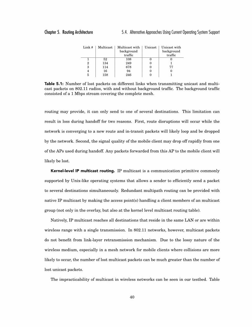
Table 5.1: Number of lost packets on different links when transmitting unicast and multi-cast packets on 802.11 radios, with and without background traffic. The background trafficconsisted of a 1 Mbps stream covering the complete mesh.
routing may provide, it can only send to one of several destinations. This limitation can
result in loss during handoff for two reasons. First, route disruptions will occur while the
network is converging to a new route and in-transit packets will likely loop and be dropped
by the network. Second, the signal quality of the mobile client may drop off rapidly from one
of the APs used during handoff. Any packets forwarded from this AP to the mobile client will
likely be lost.
Kernel-level IP multicast routing. IP multicast is a communication primitive commonly
supported by Unix-like operating systems that allows a sender to efficiently send a packet
to several destinations simultaneously. Redundant multipath routing can be provided with
native IP multicast by making the access point(s) handling a client members of an multicast
group (not only in the overlay, but also at the kernel level multicast routing table).
Natively, IP multicast reaches all destinations that reside in the same LAN or are within
wireless range with a single transmission. In 802.11 networks, however, multicast packets
do not benefit from link-layer retransmission mechanism. Due to the lossy nature of the
wireless medium, especially in a mesh network for mobile clients where collisions are more
likely to occur, the number of lost multicast packets can be much greater than the number of
lost unicast packets.
The impracticability of multicast in wireless networks can be seen in our testbed. Table
40
Chapter 5. Routing Architecture 5.4. Alternative Approaches Using Current Operating System Support
5.1 shows the number of lost packets at different links when using unicast and IP multicast
to transmit packets. We sent 1,000 packets on different links at different times, with and
without background traffic in the network. The wireless routers had default retransmit limit
of 4 for unicast packets. As we can see, the loss rate for multicast streams varies between 1%
and 67% while unicast streams experience at most 7% loss.
Kernel-level IP multicast routing with unicast tunnels. Some IP multicast protocols are ca-
pable of using unicast tunnels on each link. These protocols, overviewed in [13], were mainly
developed to support multicast on wide area networks. Achieving redundant multipath with
these protocols requires two levels of indirection per packet. First, since the destination of the
packet is the IP of the actual mobile client, we must create a mesh end-to-end tunnel with the
mesh-node that first sends the packet as the source and the multicast address that is used
to manage the client as the destination. Then, another unicast tunnel, commonly known as
virtual interface, must be created for each link in the mesh. Both tunnel headers must be
stripped out before sending the original packet to the mobile client, thus allowing seamless
end-to-end communication. Managing these tunnels adds unwanted complexity to the sys-
tem, requires modifications of the packet at each hop (replacement of one tunnel header with
another one), and also increases the packet size with two tunnel headers.
User-level overlay routing. User-level overlay routing allows users to implement any
protocol without requiring any special support from the kernel. In early stages of develop-
ment, SMesh routing architecture used an user-level overlay system. While very convenient,
routing the entire traffic through user space is challenging for resource-constraint devices.
In Section 5.6 we evaluate the performance of user-level routing using off-the-shelf Linksys
WRT54G routers, and show that even on a single hop, using only a wired connection, the
maximum forwarding throughput achieved is about 2.1 Mbps due to CPU saturation.
41
Chapter 5. Routing Architecture 5.4. Alternative Approaches Using Current Operating System Support
5.4.1 Discussion of Tradeoffs
Table 5.2 summarizes the tradeoffs of the routing mechanisms we presented in previous sec-
tion. We compare them in terms of performance, packet overhead, and amount of kernel mod-
ifications required to implement them. Since we focus on wireless mesh networks, we also
consider wireless reliability (the ability to take advantage of the 802.11 link-layer retrans-
missions) and path redundancy for mobility among the metrics. As we show in Section 5.5,
generic redundant multipath support may be useful in other kinds of applications, therefore,
we include this feature in the comparison, too.
Among the kernel-based routing mechanisms, unicast routing (first alternative) seems
to be the easiest approach but it gives up the redundancy in favor of using kernel unicast
forwarding to achieve high throughput. It does not add any overhead per packet and it can
provide good performance depending on mesh topology and client movements.
The first IP multicast-based approach, while providing redundancy, cannot be a viable op-
tion for wireless environments where the loss rate, even between two adjacent access points,
is high. In addition, this method requires one tunnel header in which the entry point in the
mesh network is encoded. For generic applications such as those presented in Section 5.5,
this method cannot provide path redundancy because a tree is not a good abstraction for
these situations3. This drawback is also shared by the second type of multicast-based proto-
cols, those in which we can use an additional hop-by-hop tunnel to trigger 802.11 link-layer
retransmissions. This tunnel header must be replaced at each hop along the path of a packet.
The user-space overlay routing, while adding an overlay header per packet, is advanta-
geous when processing power of the routers is not an issue. As it is based on unicast hop-by-
hop forwarding, it benefits from 802.11 link-layer retransmissions, thus providing wireless3It is however for mobility in wireless mesh networks, where the access points can join a multicast group to
Unicast (Shortest Path) high, kernel level no no yes no noMulticast 1 high, kernel level yes no no one tunnel header noMulticast 2 high, kernel level yes no yes two tunnel headers no
User-Space Overlay limited, user level yes yes yes overlay header noRedundant Multipath high, kernel level yes yes yes no very little
Table 5.2: Tradeoffs between several routing mechanisms using existing operating systemsupport.
5.5 Additional Applications for Redundant MultipathRouting
Traditionally, redundancy is equivalent to resiliency, allowing the entire system to function
as a whole when some of its components fail. In the case of routing, protocols are in general
Figure 5.6: Generic redundant multipath. The packets between the source and the destina-tion nodes can be routed with different levels of resilience (R). The resilience level is encodedin the header of the packet.
self-healing, in the sense that, upon detection of a route failure, they will search and/or estab-
lish a new routing path if one exists. The challenge lies in the process of detecting the failure,
which usually involves a timer to expire after a relatively large amount of time. While re-
ducing these timeouts is not desirable in routing protocols, as they may generate dangerous
oscillations, we believe that using redundant multipath forwarding in case of uncertainty
offers a viable solution for resilient routing.
Using the principles of our routing architecture, wireless networks could route packets
with different levels of resilience, on a per-packet basis. Consider the network shown in Fig-
ure 5.6. The source can reach the destination via multiple paths. These paths may be disjoint
and the number of paths may depend on the current state of the network and the levels of
resilience needed. The graph shows the paths for three possible levels of redundancy. Simi-
lar to our architecture, different routing tables can have entries that correspond to different
levels of redundancy. Then, each packet can carry its desired reliability level in its IPID so
that each router is able to forward the packet using the appropriate forwarding table.
Redundant multipath can also be used to send time-sensitive information in hostile en-
vironments where nodes may be compromised by an adversary. While existing Byzantine
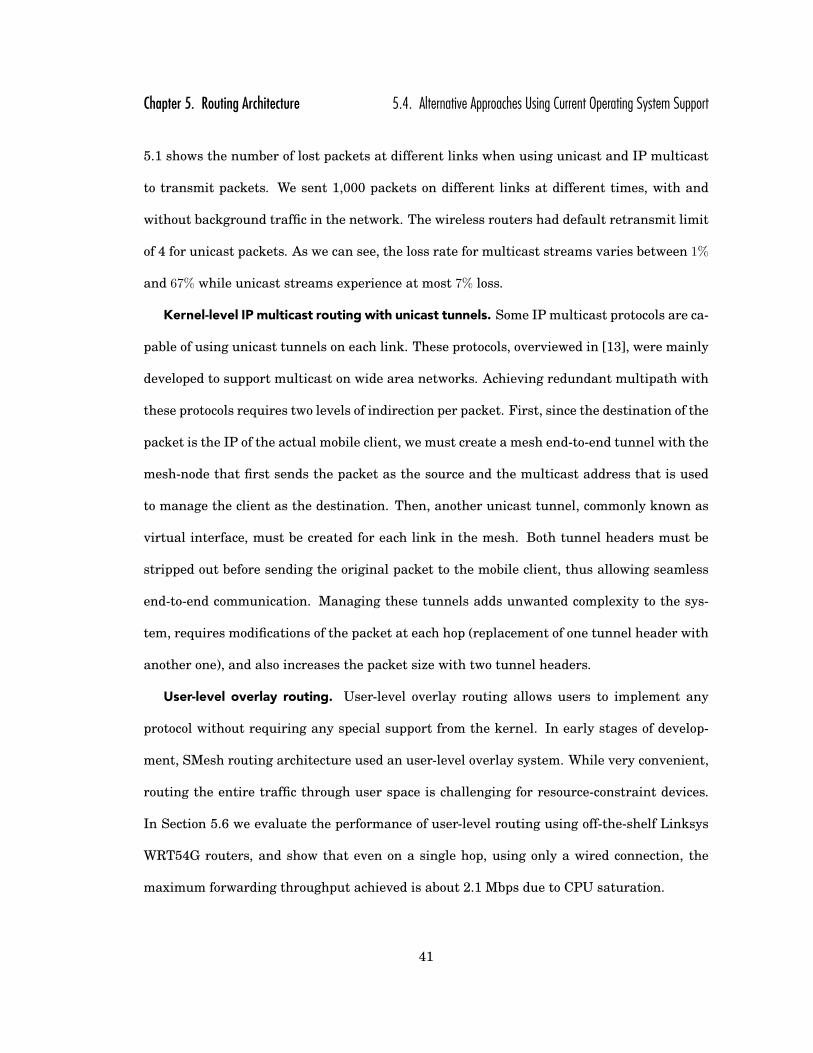
Figure 5.7: CPU load and loss rates while sending a stream of 1400-byte UDP packets withtransmission rates varying from 100 Kbps to 20 Mbps. The top x-axis shows the correspond-ing number of packets/sec.
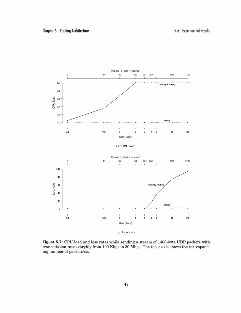
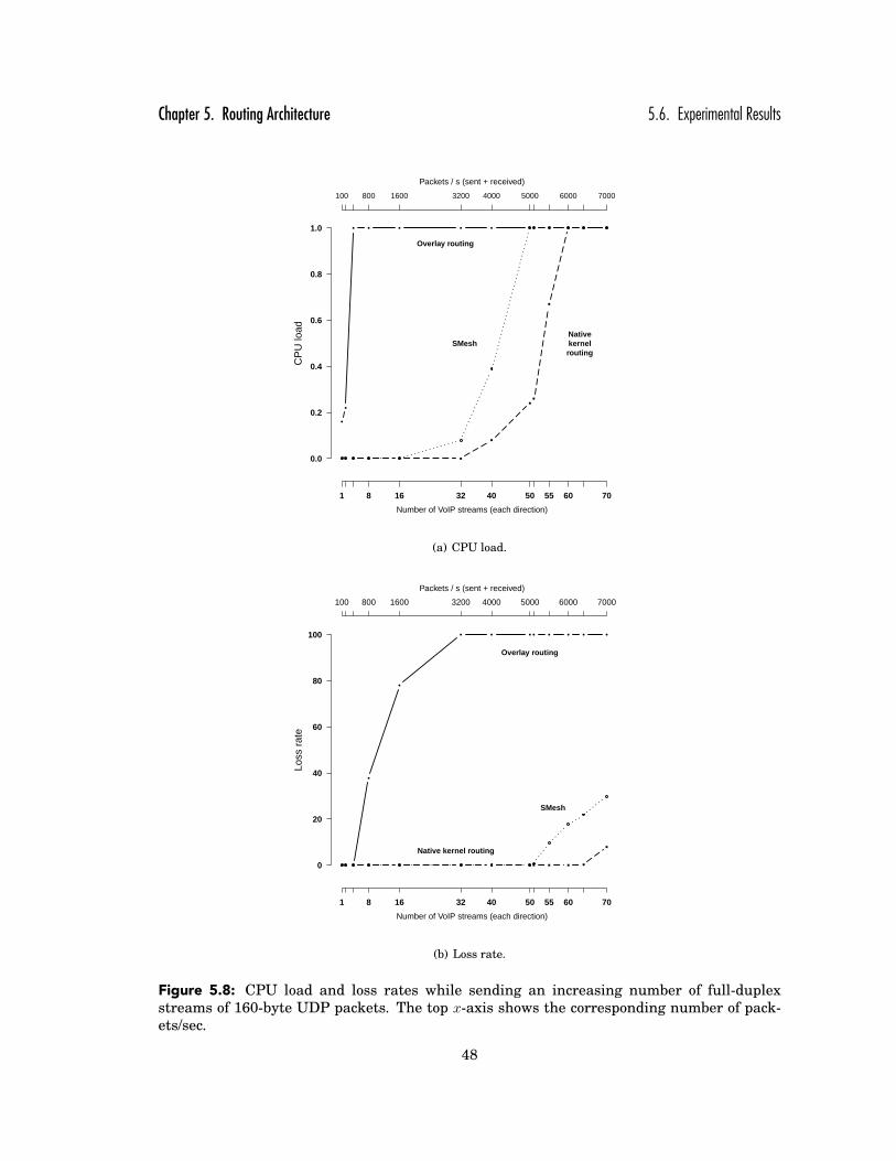
Figure 5.8: CPU load and loss rates while sending an increasing number of full-duplexstreams of 160-byte UDP packets. The top x-axis shows the corresponding number of pack-ets/sec.
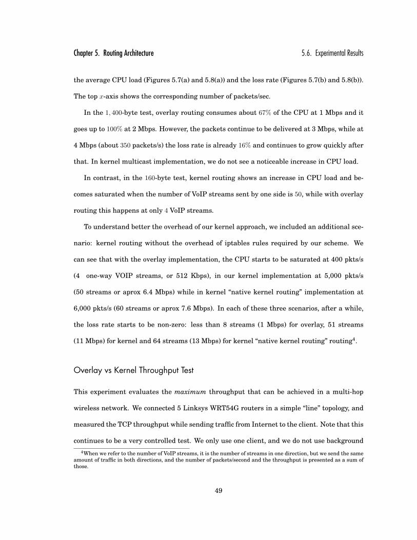
the average CPU load (Figures 5.7(a) and 5.8(a)) and the loss rate (Figures 5.7(b) and 5.8(b)).
The top x-axis shows the corresponding number of packets/sec.
In the 1, 400-byte test, overlay routing consumes about 67% of the CPU at 1 Mbps and it
goes up to 100% at 2 Mbps. However, the packets continue to be delivered at 3 Mbps, while at
4 Mbps (about 350 packets/s) the loss rate is already 16% and continues to grow quickly after
that. In kernel multicast implementation, we do not see a noticeable increase in CPU load.
In contrast, in the 160-byte test, kernel routing shows an increase in CPU load and be-
comes saturated when the number of VoIP streams sent by one side is 50, while with overlay
routing this happens at only 4 VoIP streams.
To understand better the overhead of our kernel approach, we included an additional sce-
nario: kernel routing without the overhead of iptables rules required by our scheme. We
can see that with the overlay implementation, the CPU starts to be saturated at 400 pkts/s
(4 one-way VOIP streams, or 512 Kbps), in our kernel implementation at 5,000 pkts/s
(50 streams or aprox 6.4 Mbps) while in kernel “native kernel routing” implementation at
6,000 pkts/s (60 streams or aprox 7.6 Mbps). In each of these three scenarios, after a while,
the loss rate starts to be non-zero: less than 8 streams (1 Mbps) for overlay, 51 streams
(11 Mbps) for kernel and 64 streams (13 Mbps) for kernel “native kernel routing” routing4.
Overlay vs Kernel Throughput Test
This experiment evaluates the maximum throughput that can be achieved in a multi-hop
wireless network. We connected 5 Linksys WRT54G routers in a simple “line” topology, and
measured the TCP throughput while sending traffic from Internet to the client. Note that this
continues to be a very controlled test. We only use one client, and we do not use background4When we refer to the number of VoIP streams, it is the number of streams in one direction, but we send the same
amount of traffic in both directions, and the number of packets/second and the throughput is presented as a sum ofthose.
Figure 5.9: The average TCP throughput between the Internet and a client situated at dif-ferent hops away from the Internet gateway. The routers are in a simple “line” topology.
traffic to influence our results, as our goal is to obtain the throughput upper bound. In
the experiment we did not use the RTS/CTS mechanism for collision avoidance, as previous
studies show that it does not provide a higher TCP throughput [25] [75].
We performed tests with the client placed 1, 2, 3, 4 and 5 hops away from the Internet
gateway. The throughput results are presented in Figure 5.9. We also measured the round
trip time (RTT) for both, overlay and kernel routing (Figure 5.10).
With the overlay implementation, the maximum throughput was about 2.1 Mbps for 1 hop
and it slowly decreased to 1.7 for 5 hops. In the kernel scheme we obtained a throughput of
10.1 Mbps for 1 hop, which decreased by half, to about 5.1 Mbps for 2 hops. We believe this
is due to the influence of inter-hop interference. We notice that even if our scheme yields
quite bit of improvement when the number of hops is low, at 5 hops away from the Internet
gateway, the difference between overlay and kernel methods is relatively small (2.1 Mbps for
kernel versus 1.75 Mbps for overlay). Placing multiple Internet gateways in an wireless mesh
network will prevent having a very low throughput by decreasing the number of wireless hops
Figure 5.10: The average RTT between the Internet and a client situated at different hopsaway from the Internet gateway. The routers are in a simple “line” topology.
to the clients.
The round-trip times are averaged over the duration of each test (Figure 5.10). In the
overlay implementation, the RTT increases from 59 ms for 1 hop to 71 ms for 5 hops, while
in the kernel implementation, it increases from 13 ms to 64 ms for 5 hops. In both situations,
we also show the RTT when no traffic is present. We notice again the influence of link-layer
collisions, which cause packet loss, trigger 802.11 retransmissions, and increase the packet
latency. The round-trip latency from overlay is more than 3 times the one from kernel for
1 hop, and even at 4 hops it is much above the kernel implementation.
Overlay vs Kernel in deployed testbed
This experiment evaluates the TCP throughput and packet latency for a mobile client walking
throughout our deployed testbed of 17nodes.
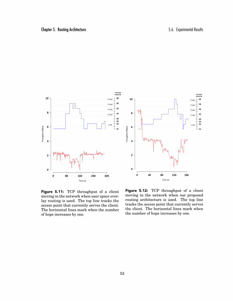
TCP throughput. Figures 5.11 and 5.12 present the TCP throughput achieved over time in
both overlay and kernel modes. In order to see how far we are from the Internet gateway, we
plot with a dotted line the access point that currently services the client. The horizontal lines
mark when the number of hops increases by one. To simplify the graphs, we included only
Figure 5.11: TCP throughput of a clientmoving in the network when user space over-lay routing is used. The top line tracks theaccess point that currently serves the client.The horizontal lines mark when the numberof hops increases by one.
Time (s)
Thr
ough
put (
Mbp
s)
0 40 80 120 160
0
2
4
6
8
10
1 hop
2 hops
3 hops
4 hops
5 hops
31
323336
24
25
26
28
AccessPoint ID
Figure 5.12: TCP throughput of a clientmoving in the network when our proposedrouting architecture is used. The top linetracks the access point that currently servesthe client. The horizontal lines mark whenthe number of hops increases by one.
Figure 5.13: CDF of the one-way latency of the packets delivered to a client moving through-out the mesh. The traffic is a full-duplex 64 Kbps UDP stream.
the routers that were involved in handling the client.
With the overlay routing, the throughput is just above 2 Mbps if the client is 1 or 2 hops
away from the Internet gateway (routers 31 and 32, 33 and 36). This is consistent with the
throughput reported in the previous test. As the number of hops increases, the throughput
drops to 1 Mbps and even lower. In the kernel routing, the throughput was about 8.5 Mbps
for 1 hop access points, 4.3 Mbps for 2 hops and it drops to 1 Mbps when the client is 6 hops
away from the gateway (router 28). In both cases, the wireless link losses prevented us from
achieving the throughput obtained in the controlled test (Figure 5.9).
UDP latency. We compare the improvement of packets latencies when routing in overlay and
in kernel modes. We use a full-duplex UDP traffic, consisting in 160-byte packets sent every
20 ms at a rate of 64 Kbps, for 5 minutes. We focused on a VoIP-like traffic as a representative
application that poses severe latency requirements. As opposed to the RTT presented in the
controlled test (Figure 5.10), we measure the one-way latencies. Figure 6.12 shows a CDF
of the packets latency. We can see that about 80% of the packets were delivered in under
10.5 ms using the overlay while in the kernel implementation they arrived within 3.7 ms.
54
Chapter 6
Application: Push-To-Talk Service for FirstResponders
Push-To-Talk (PTT) is a well known service in the law enforcement and public safety commu-
nities, where coordination and spectral efficiency are key for efficient communication. Some
cell phone companies offer a similar service in the commercial world. However, core differ-
ences in motivation drive these two sectors. Cellular phone systems are designed for the
busiest hour, as outages impact revenue, while public safety systems are designed for worst
case scenarios, as outages impact lives.
Unfortunately, first responders cannot always rely on pre-existing ground communication
infrastructure. For example, the White House report on hurricane Katrina [9] states that
1,477 cell towers were incapacitated, leaving millions unable to communicate. The report con-
cludes that “The complete devastation of the communications infrastructure left emergency
responders and citizens without a reliable network across which they could coordinate.”
Wireless mesh networks have emerged as a viable technology that allows for rapid deploy-
ment of instant infrastructure [71]. In these networks, mobile clients can roam throughout
the area covered by the mesh and seamlessly handoff between access points while utilizing
real-time applications such as VoIP [16, 40]. These attributes make wireless mesh networks
an appealing technology for first responders. While centralized solutions for providing PTT
55
Chapter 6. Application: Push-To-Talk Service for First Responders
service exist (e.g., POC [12]), there are currently no solutions for a robust and efficient PTT
service that can be applied in much more dynamic environments such as wireless mesh net-
works.
Because it relies on half-duplex communication, a PTT system requires an arbitration
mechanism (also known as floor control), which determines the order in which participants
speak. All participants that wish to communicate with each other form a PTT group. As the
name suggests, they request to talk by pressing a button. In contrast to peer-to-peer VoIP
systems, data must be disseminated from the speaker to all the participants in a given PTT
group.
Building a robust and practical Push-To-Talk system for the wireless mesh environment
is challenging for several reasons. First, it requires the ability to coordinate communication
between users even when part of the infrastructure is unavailable (mesh node crashes) or
when there is intermittent connectivity between nodes (network partitions and merges). This
rules out traditional approaches such as POC, where arbitration is assured by a centralized
point. Second, it must operate correctly when users join and leave the network, when they
are partitioned away, lose their connectivity, or move from one access point to another. Third,
it must use the wireless medium efficiently and should provide low transfer times between
users’ requests. Last but not least, an important property for first responders is the ability
to integrate regular PSTN (Public Switched Telephone Network) and cellular phone users,
allowing them to seamlessly participate in the PTT sessions conducted by the wireless mesh
PTT service at a disaster site.
We present here the first architecture and protocol of a robust distributed PTT service
for wireless mesh networks. Collectively, the mesh nodes provide the illusion of a single
third party call controller (3pcc), enabling clients to participate via any reachable mesh node.
Mesh users with SIP-based VoIP phones participate by connecting to an IP address that
56
Chapter 6. Application: Push-To-Talk Service for First Responders
Figure 6.1: Overview of the Push-To-Talk system. Mesh users connect to the system usinga SIP-based VoIP application. Phone users connect via the PSTN network to a SIP gatewaythat routes their calls to the mesh network.
corresponds to the virtual 3pcc server address. In addition, regular phone and cell phone
users dial a phone number that connects to the mesh network through a SIP gateway that
routes the call to the mesh (Figure 6.1).
In our approach, each PTT group (also referred to as a PTT session) instantiates its own
logical floor control manager that is responsible for keeping track of the floor requests of the
participants and for issuing Permission-To-Speak when a participant releases the floor. Any
of the mesh nodes in the network can play the controlling role for a session. To maintain high
availability, each controller node is continuously monitored by every mesh node with a partic-
ipating PTT client and is quickly replaced if it becomes unavailable due to a crash or network
partition. The controller relinquishes its role to another mesh node upon determining that
this node is better situated (network-wise) to control the PTT session, based on the current
locations of the clients participating in the session. In addition to improved performance, this
migration increases the availability of the service in the face of network partitions because it
keeps the controller in the “center of gravity” of the clients in the PTT session.
The main contributions of this work are:
i) The first robust Push-To-Talk service for wireless mesh networks that can withstand
connectivity changes such as node crashes, network partitions, and network merges.
57
Chapter 6. Application: Push-To-Talk Service for First Responders 6.1. Push-To-Talk System Architecture
ii) Novel use of multicast for localized access points coordination to share PTT client state,
such that the entire network appear to the client as a single call controller.
iii) Novel decentralized floor control protocol that maintains a different logical controller for
each PTT session and adaptively migrates it to the most suitable node in the network.
iv) The first architecture that allows regular PSTN phones users (e.g., cell phone users) and
unmodified VoIP SIP phones to seamlessly participate in PTT sessions.
We implemented this Push-To-Talk architecture and protocol within the SMesh system
and evaluated using a set of 14 nodes from our testbed. In our tests, users experienced less
than 150 ms interruption while the system switches between speakers. We show how the
system scales to tens of clients, with an overhead of under 1 Kbps per client with 42 clients
in the mesh. Then, we show that in our testbed, the system scales to 18 simultaneous PTT
groups when dual-radio and packet aggregation are used. Lastly, an elaborate scenario with
40 clients divided among 10 different PTT sessions demonstrates that the system remains
highly available during mesh network connectivity changes.
6.1 Push-To-Talk System Architecture
The mesh topology changes when wireless connectivity between the mesh nodes changes,
when mesh nodes crash or recover, or when additional mesh nodes are added to expand the
wireless coverage. These changes may create network partitions and merges in the wireless
mesh.
Push-To-Talk users are regular mesh clients, that is, unmodified 802.11 devices. We do not
assume any specific drivers or hardware capabilities present on the clients. Clients connect
to the mesh by associating with the wireless-mesh 802.11 SSID. A client should be able to
participate with any compliant VoIP application. Therefore, any regular unmodified mobile
58
Chapter 6. Application: Push-To-Talk Service for First Responders 6.1. Push-To-Talk System Architecture
Mes
h N
ode
Client Control Group
PTT CMonitor
Group
PTT Data Group
PTT Controller
Group
PTT ControllerMobile, Fault-Tolerant
Monitor Floor Management
Mobile Client State sip_call_id, sip_cseq, rtp_port, ptt_group, ptt_state
PTT Session Manager
RTP Proxy
DTMF Voice
DistributedSIP 3PCC
Mobile Client with VoIP Software
SIP RTP
Routing Daemon (Discovery, Topology Management, Group Management)
Wireless Mesh Network
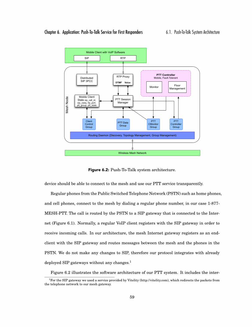
Figure 6.2: Push-To-Talk system architecture.
device should be able to connect to the mesh and use our PTT service transparently.
Regular phones from the Public Switched Telephone Network (PSTN) such as home phones,
and cell phones, connect to the mesh by dialing a regular phone number, in our case 1-877-
MESH-PTT. The call is routed by the PSTN to a SIP gateway that is connected to the Inter-
net (Figure 6.1). Normally, a regular VoIP client registers with the SIP gateway in order to
receive incoming calls. In our architecture, the mesh Internet gateway registers as an end-
client with the SIP gateway and routes messages between the mesh and the phones in the
PSTN. We do not make any changes to SIP, therefore our protocol integrates with already
deployed SIP gateways without any changes.1
Figure 6.2 illustrates the software architecture of our PTT system. It includes the inter-1For the SIP gateway we used a service provided by Vitelity (http://vitelity.com), which redirects the packets from
the telephone network to our mesh gateway.
59
Chapter 6. Application: Push-To-Talk Service for First Responders 6.2. Interface with Mobile Clients
face with the mobile client, the mesh PTT session manager for the mobile client, and the
mesh PTT controller for each PTT session in the wireless mesh network. Various multicast
groups, over which communication takes place, are shown. We benefit from the underly-
ing routing infrastructure, which provides us with overlay group management to effectively
communicate on a group-based abstraction.
Each of these components is described in detail in the next sections.
6.2 Interface with Mobile Clients
A mobile client should be oblivious to the heavyweight protocols employed in the mesh net-
work. Further, we want to allow any 802.11 client, as well as PSTN clients, to use the PTT
service without changing any of the standards. To do so, our architecture interacts with
clients by using well established VoIP protocols.
VoIP applications use the Session Initiation Protocol (SIP [67]), to establish, modify, and
terminate a VoIP session. During the SIP session establishment, the Session Description
Protocol (SDP [41]) is used to describe the content of the session (i.e., voice), the underlying
transport protocol (i.e., RTP2), the media format, and how to send the data to the client
(address, port, etc). Data is then sent using the designated transport protocol between the
parties.
A third party call control (3pcc) server is normally used to inter-connect multiple parties
together through a rendezvous point. Conference call managers are one type of 3pcc. Good
practices for SIP-based VoIP 3pcc servers are specified in RFC 3725 [66]. In essence, from an
end-client point of view, the 3pcc server looks exactly the same as another end-client.
In our architecture, all mesh nodes act as a single 3pcc server and share the state of
the SIP connection with every other mesh node in the vicinity of the client (between mesh2Real-time Transport Protocol (RTP) is a standard protocol (RFC 3550) that provides end-to-end delivery services
for data with real-time characteristics, such as interactive audio and video.
60
Chapter 6. Application: Push-To-Talk Service for First Responders 6.2. Interface with Mobile Clients
nodes that can hear the client). This is key for the system to scale as it efficiently shares
information only between nodes that can potentially need the state of the SIP connection as
the client moves throughout the mesh, or in case the client’s mesh node crashes.
To participate in the mesh PTT session, the user specifies in its VoIP application the IP
address of our virtual SIP server (i.e., “sip:[email protected]”). This IP is the same throughout
the mesh. Every mesh node intercepts packets sent to this address and follows the SIP
protocol to connect the client to the mesh. Therefore, the mesh network provides the illusion
of a single 3pcc to the client.
Once a SIP connection is established, the user can start using the mesh PTT service by
simply dialing the PTT group that it wishes to join. Each dialed key generates a Dial-Tone
Multi-Frequency (DTMF [68]) signal that is sent over the RTP channel (by default, this signal
is repeatedly sent over multiple RTP packets to ensure that the end-node receives it). In our
approach, we intercept DTMF signals for control purposes between the end-client and the
mesh. For example, a client dials “#12#” to join PTT group 12. In the same way, every time
a user wishes to speak, pressing “5” or any pre-defined key combination will be interpreted
as a “Request-To-Speak” control message. Once the system determines that it is the user’s
turn, it sends an audio signal (“beep-beep”) to let the user know that it can start to speak.
While other means for signaling control information are possible, DTMF is supported by
most communication networks such as PSTN, allowing us to seamlessly support users from
these networks.
RTP data is then sent from the client to the 3pcc virtual IP address through the client’s
access point (mesh node), which forwards the packets to every mesh node that has a PTT
client on that group using a source-based multicast tree. Finally, each receiving mesh node
forwards the packets to its corresponding end-clients.
61
Chapter 6. Application: Push-To-Talk Service for First Responders 6.3. Push-To-Talk Protocol
6.3 Push-To-Talk Protocol
Providing a robust and scalable way to coordinate client communication is the essence of the
Push-To-Talk protocol. There are several ways to approach it. One possibility is to have a
unique point of management in the network that every mesh node needs to contact in order
to register a request and get permission to speak. Such a protocol is easy to design and im-
plement and is appropriate for deployment in certain environments. However, this approach
is not a good choice for networks that require high availability. For example, if a partition
occurs in the mesh, all the clients connected to nodes that cannot reach the arbitration point
will be left out of service. At the opposite extreme is the approach of total decentralization
in which there is no unique entity that arbitrates the communication. Instead, the nodes in
the mesh must coordinate and collectively decide on the order of serving the clients. While
more complex, such a protocol is very resilient to infrastructure failures, at the expense of
a continuous communication overhead in order to maintain a consistent view between the
mesh nodes in the network.
Our PTT architecture uses a hybrid protocol that shares characteristics with both ap-
proaches. As in the centralized approach, each PTT session is managed by a controller node
which is responsible for keeping track of floor requests and for issuing Permission-To-Speak
after a participant releases the floor. However, each PTT session has is own controller node
and any of the mesh nodes in the network can play the controlling role for any session. The
controller node is continuously monitored by other nodes and rotated when a more suitable
node (i.e., a node with a better geographical position in the network) becomes available.
In addition, we completely separate floor control from data dissemination. While the
arbitration is left to the best node to be the controller, the data is routed optimally to all
participants through source-based multicast trees. This allows the system to be efficient and
62
Chapter 6. Application: Push-To-Talk Service for First Responders 6.3. Push-To-Talk Protocol
controllerchange
Figure 6.3: The multicast groups maintained by the system to manage a client (Control) andits PTT session (CMonitor, Data, Controller).
scalable.
The details of our protocol are presented below. We start by describing how a mobile
client is managed by a mesh node and how a PTT session is managed by a controller. We
then present the floor arbitration mechanism. Finally, we show how the protocol withstands
node crashes and connectivity changes such as network partitions and merges.
6.3.1 Client Management
For a PTT client, the entire mesh network behaves as a single 3pcc server. This is achieved
by maintaining the state of the client on the mesh nodes in the vicinity of that client, such
that any node that becomes the client’s access point (the client is mobile) has the appropriate
SIP and PTT information. A virtual IP is assigned to the 3pcc server, and is used by the client
VoIP application to connect to.
Specifically, in order to service a client, the system requires information such as the SIP
call identifier, SIP sequence number, RTP port, PTT group, PTT state (e.g., the client requests
permission to speak, or has permission to speak). We chose to maintain client’s state locally
63
Chapter 6. Application: Push-To-Talk Service for First Responders 6.3. Push-To-Talk Protocol
for several reasons. First, there is no single node responsible for the state. Instead, any node
that can hear the client maintains a state for it. Thus, the state is preserved even when
the client’s access point crashes. Second, as the state is maintained in the vicinity of the
client, the overhead is localized in the part of the network where the client is located. Finally,
the client state is decoupled from the controller node, allowing the clients’ requests to be
recovered when the controller node crashes (or is partitioned away), as we discuss below.
Client Control Group. To share the client state between mesh nodes that can reach a
client, we associate with each client an overlay multicast group. Specifically, any node that
can hear the client (that is, not only its current access point) joins and periodically advertises
the client state on the Client Control Group (Figure 6.3). In our experiments, we share this
information every four seconds. Note that the system is not synchronized and different nodes
may see different states for a client at a given time. We use a combination of client times-
tamps (available in the SIP and RTP packets) and controller logical timestamps to correctly
identify the most recent state of a client. This multicast group is an extension of the Client
Control Group introduced in Section 4.3.
Using a localized multicast group per client has another benefit: The client is mobile and
it can freely move from one access point to another. When the client is granted permission
to speak, the controller node uses this group to reach and notify the client, without actually
having to keep track of its current access point (a node can send a message to a multicast
group without being a member of the group).
6.3.2 Session Management
A client joins a PTT session by initiating a VoIP conversation with the virtual 3pcc server as
described in Section 6.2, independently of its network location. In our protocol a PTT session
64
Chapter 6. Application: Push-To-Talk Service for First Responders 6.3. Push-To-Talk Protocol
is coordinated by a controller node, whose presence is continuously monitored by other nodes.
The controller relinquishes its role to another mesh node upon determining that this node is
better situated (network-wise) to control the PTT session, based on the current location of
the clients participating in the session. Three multicast groups are used to manage a PTT
session in a distributed manner.
PTT Controller Group (PTT CONTROLLER). For each PTT session, there is a single mesh
node, the controller, responsible for managing the floor at a given moment in time. It receives
and arbitrates requests and grants the right to speak. In our architecture, when a node
becomes the controller for a PTT session, it joins an overlay multicast group associated with
that session. Maintaining an overlay multicast group with the controller as the only member
allows any mesh node in the network to reach the controller node without actually knowing
its identity. Unicast communication with the controller is used by the protocol, however, only
in response to a message previously received from the controller. All client floor requests
are sent by their access points (mesh nodes) to this group and are stored by the controller
in a FIFO queue. Periodically, the controller checks whether another mesh node is more
appropriate to manage the PTT session. In such a case, it initiates a procedure to migrate
the control to that node.
PTT Controller Monitoring Group (PTT CMONITOR). This overlay multicast group is used
to monitor the controller node. A mesh node joins the monitoring group of a PTT session if
it is the access point of a client that participates in that session. In addition, the controller
joins this group to detect the presence of another controller during a network merge. A ping
message is periodically sent by the controller to this group, allowing its members to monitor
controller’s presence and take action if the controller is no longer available.
PTT Data Group (PTT DATA). This multicast group is used to deliver the actual voice data
to the clients. A mesh node joins the PTT Data Group of a session if it is the access point
65
Chapter 6. Application: Push-To-Talk Service for First Responders 6.3. Push-To-Talk Protocol
of a client in that session. Thus, we completely separate floor arbitration, coordinated by a
single controller node, from data dissemination. This allows us to optimally route data from
the sender node to all the participants in a PTT session.
To simplify the management of names for these three multicast groups, we generate their
IP multicast addresses using a hash function of the PTT session identifier, such that any
mesh node in the network knows which groups are associated with each PTT session without
coordination. Similarly, the Client Control Group is generated as a hash of the client IP
address.
6.3.3 Floor Control
Requests handling
Figure 6.4 describes how the controller arbitrates the floor such that only one user speaks at
a time, while all other users listen.
When a PTT client requests the floor, a REQUEST FLOOR message is sent by its access
point to the PTT CONTROLLER group. The controller queues the request and sends back an
acknowledgment. Since the messages are not reliable, the access point will retransmit the
request until it receives an acknowledgment from the controller, or until the client cancels its
request. Note that the acknowledgment is sent on unicast, to the access point of the client.
Release floor requests are sent to the controller in a similar manner. When a
RELEASE FLOOR is received, the controller node grants the right to speak to the next client
in the queue by sending a PTS (Permission-To-Speak) message. This message is sent to the
client via the Client Control group. We do this because during the life of a PTT session,
the client location can change, and it may no longer be associated with the access point that
initially issued the request to speak. If the client is no longer available, a simple timeout
66
Chapter 6. Application: Push-To-Talk Service for First Responders 6.3. Push-To-Talk Protocol
PTT node Controller node
Receive floor requestfrom a client
Queue the request
REQUEST_FLOOR (client)PTT_CONTROLLER group
REQUEST_ACK (client)
unicast
timeoutretry
Receive floor releasefrom a client
Handle the next request from the queue
RELEASE_FLOOR (client) ortime exceededPTT_CONTROLLER group
RELEASE_ACK (client)
unicast
timeoutretry
Permission-to-Speak
client CONTROL group
Send PTS voicesignal to the client PTS_ACK (client)unicast
timeoutretry [3 times]
Client unreachableHandle next client in the queue
Figure 6.4: The sequences of steps performed by the mesh node and the controller node inorder to service user requests. The first part shows how an user requests to speak, whilesecond part shows how the user is notified when its permission to speak is granted.
67
Chapter 6. Application: Push-To-Talk Service for First Responders 6.3. Push-To-Talk Protocol
Controller PTT node
A better controller is available
Stop queueing and handling requests
Join PTT_CMONITOR (if not already there) and PTT_CONTROLLER groups
Start queuing and handling requests
INVITE (group, Queue)unicast
INVITE_ACK (group)
unicast
timeoutretry [3 times]
Controller change failed
Start queueing and handling requests
Controlled change succeeded
Leave PTT_CMONITOR(if needed) and PTT_CONTROLLER groups
Figure 6.5: The sequence of steps and actions performed to migrate the controller. The mi-gration process is initiated by the current controller, based on existing network conditions.
mechanism allows the controller to move to the next request in its queue.
Migrating the controller
While there is a single controller node for a PTT session at a given time, the system may
change the controller over time, depending on participants’ placement in the network. The
idea is to avoid situations such as when a majority of the clients in a PTT session are localized
in some part of the network while the controller node is in another. Placing the controller
closer to where most participants are reduces the latency and the amount of control traffic in
the network. In addition to improved performance, this migration increases the availability
of the service in the face of network partitions because it keeps the controller in the “center
of gravity” of the clients in the PTT session. Specifically, the system computes the cost that
68
Chapter 6. Application: Push-To-Talk Service for First Responders 6.3. Push-To-Talk Protocol
each node would incur if it was the controller as the sum of the costs to reach each member
of PTT DATA group. In our experiments we computed this cost every minute. By cost we refer
to a wireless metric that may incorporate latency or the number of hops, for example3. Note
that any node in the mesh network can be chosen to be a controller, regardless if it services
PTT clients.
The sequence of steps performed for migrating the controller are as follows: First, the
current controller enters a block state, in which it does not respond to any floor requests or
releases and does not grant the right to speak to any client. Next, the controller sends an
INVITE message to the selected node—the one with the lowest cost to be a controller—which
includes the queue of the pending requests. Upon receiving such a message, the invited node
joins the PTT CMONITOR group—in case it was not already a member—and also joins the
PTT CONTROLLER group. It now has the queue of requests and can safely begin controlling
the session, queuing new requests and issuing PTS. An acknowledgment is sent back to the
initial controller so that it can leave the PTT CONTROLLER group. In case of a timeout during
this process, the original controller unblocks and continues to manage the PTT session.
6.3.4 Protocol Robustness
Due to the inherent instability of the wireless environment, it is possible for the network to
partition and merge. While in a well-established mesh network this should rarely happen,
a rapidly deployed network during an emergency is likely to experience such problems. In
addition, any node in such a network can crash. The PTT service must continue to operate
even if it experiences a few seconds of interruption. Below we explain how the protocol is
resilient to these conditions.3Additional functionality from was added to retrieve topology and membership information from the link-state
and group-state updates, which in turn allows a controller to compute the Euclidean distance from every node to agiven PTT group.
69
Chapter 6. Application: Push-To-Talk Service for First Responders 6.3. Push-To-Talk Protocol
Network ControllerPING_CMON
PTT_CMONITOR group
Controller lost
Join PTT_CONTROLLER (if lowest IP)
Start queueing and handling requests
timeout
PTS_PING (client)
PTT_CONTROLLER groupSending node
Sending node lost
Handle the next clientin the queue
timeout
Sending clientVoice
Client not respondingSend RELEASE
timeout
monitors monitors monitors
Figure 6.6: Mechanisms that ensure the protocol robustness. The critical components (thecontroller nodes and sending nodes) are continuously monitored and re-instantiated if theconnectivity is lost because of a node crashes or the network partitions.
To operate correctly, there must be a controller and a sending node (that is, a node with a
client with permission to speak) for each PTT session. If one of these is missing, either there
is nobody to arbitrate the floor or nobody is currently speaking as the system waits for a node
which is no longer available. Thus, we introduce the following mechanisms to monitor the
operation of each of these two nodes (Figure 6.6). Note that asymmetric links are eliminated
by the routing protocol.
Controller node monitoring
The controller node periodically sends a keep-alive message (PING CMON) to the PTT CMONITOR
group, allowing other nodes that service PTT clients for that session to monitor its presence.
When the controller crashes or is partitioned away, the node with the lowest IP address on the
PTT CMONITOR group volunteers to be the controller by joining the PTT CONTROLLER group.
However, its queue of requests is empty. We use a special flag in the subsequent PING CMON
messages to notify everybody that a new controller was instantiated. All the nodes with
pending PTT requests must re-send their requests as if they were new. This is possible be-
cause the user requests are part of the user state which is maintained and shared via the
Client Control Group. Thus, the controller’s queue is reconstructed in a best-effort way, with
the requests from the current partition. Note, however, that the order of the requests in the
70
Chapter 6. Application: Push-To-Talk Service for First Responders 6.3. Push-To-Talk Protocol
Controller PTT node
Controller lost
Join PTT_CONTROLLER (if lowest IP)
Start queueing and handling requests
timeout
PING_CMONPTT_CMONITOR group
Figure 6.7: The controller is considered lost when its presence messages sent on the moni-toring group timeout. The node with the lowest IP address becomes the new controller of thesession.
new queue may be different than the one from the original controller. With minimal changes,
the protocol can be adapted to recover part of the original order established by the previous
controller.
Another situation from which we have to recover is when there are multiple controllers in
the network. This occurs after a network merge but also when the controller is lost and mul-
tiple nodes decide to control the session (unlikely but possible, as the nodes can temporary
have a different view of the network’s topology). Figure 6.8 shows the mechanism to recover
from this situation. Since the controller node is the only one sending keep-alive messages
on the PTT CMONITOR group, receiving a keep-alive that is not its own indicates to the con-
troller that there is at least one additional controller in the network. Once this situation is
detected, the node with the lowest IP address remains the controller, while the other(s) must
leave the controller’s group. A redundant controller sends a LEAVE REQUEST message to the
PTT CONTROLLER group with the content of its queue as it leaves the group. Upon receiving
such a message, the controller with the lowest IP appends the queue to its own, removing
duplicate requests if necessary, and acknowledges the leave.
71
Chapter 6. Application: Push-To-Talk Service for First Responders 6.3. Push-To-Talk Protocol
Controller(lower IP address)
Controller(higher IP address)
Another controller is available
Stop queueing and handling requests
Leave PTT_CMONITOR (if needed) and PTT_CONTROLLER groups
LEAVE_REQUEST_ACK (group)unicast
LEAVE_REQUEST (Queue)
PTT_CONTROLLER
timeout Attempt to leave failed
Start queueing and handling requests
Merge queues
PING_CMONPTT_CMONITOR group
Figure 6.8: Sequence of steps and actions taken to detect and recover from the situation whenthere are multiple controllers in the network. This happens whenever two partitions of thenetwork merge, or because the nodes may temporary have a different view on the network’stopology.
72
Chapter 6. Application: Push-To-Talk Service for First Responders 6.3. Push-To-Talk Protocol
Sending node monitoring
While the members of PTT CMONITOR group monitor the controller, the controller in turn is
responsible for monitoring the sending node (Figure 6.6). The sending node periodically is-
sues a keep-alive message (PTS PING - Permission-To-Speak Ping) on the PTT CONTROLLER
group. This allows the controller to quickly move to the next client in the queue in case of
a timeout. An alternative to this approach would be to simply wait for the maximum allot-
ted time per speaker to expire; however, system responsiveness is important in emergency
situations, ruling this option out.
Sending node Controller
Speaker node lost
Handle the next clientin the queue
timeout
PTS_PING (client)PTT_CONTROLLER group
Figure 6.9: The sending node is considered lost when its presence messages sent on thePTT CONTROLLER group timeout. In this situation the controller will immediately move tothe next request in the pending queue.
When two or more network partitions merge, there will be multiple controllers, but also
multiple sending nodes in the network. The controller of the newly established network
withdraws the right to speak to all additional clients by sending a REVOKE message to their
access points (mesh nodes), which in turn notify their associated clients.
Table 6.1 presents a summary of the messages handled by the controller node, including
the frequency of the PING CMON and PTS PING messages.
73
Chapter 6. Application: Push-To-Talk Service for First Responders 6.4. Experimental results
Type Sent by Sent to When
REQUEST FLOOR mesh node PTT CONTROLLER group client requests floorRELEASE FLOOR mesh node PTT CONTROLLER group client releases floorREQ REL ACK controller mesh nodePTS controller CLIENT CONTROL groupPTS ACK node controllerINVITE controller mesh node controller changesINVITE ACK node controllerLEAVE REQUEST controller controller multiple controllersLEAVE REQUEST ACK controller controller multiple controllersREVOKE controller node multiple speakersPING CMON controller PTT CMONITOR group every secondPTS PING node PTT CONTROLLER group every second when client
has PTS
Table 6.1: Types of messages sent and received by the controller node.
6.4 Experimental results
6.4.1 Setup
We implemented the Push-To-Talk protocol within the open source SMesh wireless mesh sys-
tem and evaluated using 14 nodes from the SMesh testbed, consisting of Linksys WRT54G
wireless routers deployed across several floors in three buildings at Johns Hopkins Univer-
sity.
Each of the mesh nodes is equipped with one radio configured in ad-hoc mode. The data
rate was set to 18 Mbps, the transmission power to 50 mW, and the 802.11 link-layer retrans-
mission limit to 7. Unless specified, the topology of the mesh, depicted in Figure 6.10, was
stable.
In all experiments, when a client is granted permission to speak it transmits a 64 Kbps
VoIP stream as 160 bytes UDP packets every 20 ms.
Some experiments require a large number of simultaneous clients. To support such ex-
periments, we implemented a client emulator that generated the appropriate control and
data traffic associated with the emulated client. From the 802.11 network and from the PTT
74
Chapter 6. Application: Push-To-Talk Service for First Responders 6.4. Experimental results
Figure 6.10: The wireless mesh network testbed used in the Push-To-Talk experiments.
system perspective, there was no difference between an emulated client and a real client in
terms of control and data traffic. Each client is instantiated on a mesh node, and packets
between the emulated client and its access point are always transmitted over the wireless
medium. In spite of generating the appropriate amount of traffic in the network, our metrics
(such as latency and loss rate) are reported from the mesh nodes perspective. A real client
should perceive slightly higher values. Despite this shortcoming, we resort to this method
in order to evaluate our system in a real testbed, with a large number of users. In our opin-
ion, though it requires more work and complete implementation, this method is significantly
more realistic than simulations, e.g., using ns-2 or OpNet.
6.4.2 Measurements
We present four types of experiments. First, we demonstrate the system’s normal operation
with a small number of clients. Second, we demonstrate the ability of the system to scale
with the number of clients in a PTT group. Third, we demonstrate the ability of the system
to scale with the number of PTT groups. Last, we demonstrate the robustness of the system
through its ability to handle network partitions and merges correctly while PTT sessions are
75
Chapter 6. Application: Push-To-Talk Service for First Responders 6.4. Experimental results
in progress.
Normal Operation
This experiment involves four mobile clients, each of them connected to a different mesh node
in the network (nodes 1, 2, 12, and 14 in Figure 6.10). All four clients join a PTT session and
continuously request to talk. When a client is granted the floor, it immediately speaks for
20 seconds, releases the floor, and then renews its request. Thus, the PTT session’s queue of
requests is never empty.
Figure 6.11 depicts the VoIP data throughput and our protocol overhead, as seen by
node 1. The overhead includes the control traffic of the PTT protocol as well as the SMesh
traffic associated with maintaining the mesh and the multicast groups. This overhead ranges
between 1.5 Kbps and 5.8 Kbps, with an average of 3.4 Kbps, which is reasonable considering
that each VoIP session is 64 Kbps.
Figure 6.11 also includes a view with the arrival time of each VoIP packet. The figure
shows a turnaround time of 137 ms from the moment the last packet from a client is received
to the moment the first packet from the next client’s voice stream arrives. This demonstrates
that only a small part of the time is consumed for synchronizing the PTT clients.
Scaling with the number of clients in a PTT session
To test the scalability of our system, we gradually increase the number of clients participating
in a single PTT session. Each client connects to one of the 14 mesh nodes in the network
according to a round-robin order of their identifiers (i.e., the first client connects to node 1,
the second to node 2, . . . , the 14th to node 14, the 15th to node 1, etc.) and requests to
speak. Upon acquiring the floor, each client speaks for 10 seconds, releases the floor, waits
76
Chapter 6. Application: Push-To-Talk Service for First Responders 6.4. Experimental results
Throughput
Time (s)
Sender node 2Sender node 12Sender node 14Overhead
0 10 20 30 40 50 60 70
0 Kbps
20 Kbps
40 Kbps
60 Kbps
80 Kbps
(a) Data as seen by node 1. Every 20 seconds the permission to speak is granted toa different user.
(b) Packets received by node 1 while the system transitions between users connectedto nodes 2 and 12. The time between the last packet from node 2 and the first fromnode 12 was 137 ms.
Figure 6.11: Experiment showing the normal operation of the system. Four users are con-nected to four random nodes in the 14-node testbed.
77
Chapter 6. Application: Push-To-Talk Service for First Responders 6.4. Experimental results
for another 10 seconds, and requests to speak again. Therefore, at any point, some client is
authorized to speak.
We considered three scenarios:
1) Each mesh node is equipped with a single radio.
2) Each mesh node is equipped with dual radios. The first radio is used for communication
with other mesh nodes, while the second is used for communication with the users. In this
way the mesh traffic does not interfere with the mesh-to-client traffic, as the radios can be
set on non-interfering channels. We emulated this dual-radio scenario in our single-radio
environment by generating the client’s messages locally on the corresponding mesh nodes
and by avoiding sending data packets from the mesh nodes towards the clients.
3) Each mesh node is equipped with a single radio and the mobile clients have no PTT sup-
port. In our system, one can simply participate in a PTT session using a standard VoIP
phone or application. If using G.711, a well supported VoIP codec, a duplex voice stream is
transmitted regardless of the data content. By PTT support we refer to the ability of the
user’s device to control the flow of outgoing packets, e.g, a button to suppress sending un-
necessary data when the user is not allowed to speak in the session. A silence suppression
technique employed by the codec, on the user’s device, would also be a good alternative to
reduce unnecessary data.
For the case where clients have no PTT support, there are two main disadvantages that
considerably affect performance. First, such clients continuously send VoIP packets, even
when not having the floor. These packets are dropped by the mesh node serving the client,
except for the durations when the client has acquired the floor. This case incurs considerable
overhead as clients send unnecessary packets in their vicinity. The second disadvantage is
that a node needs to send individual packets to all the clients directly connected to it, even
78
Chapter 6. Application: Push-To-Talk Service for First Responders 6.4. Experimental results
Average latency
Number of clients
1619
212518 16
2327
114
1721
2628
2 4 8 14 28 42
0 ms
20 ms
40 ms
60 ms
80 ms
100 ms
120 ms
Single radio
Dual radio
No PTT support
Figure 6.12: Average latency of the packets received by the nodes when the number of clientsin a PTT group increases from 2 to 42 (3 clients connected to each of the 14 access points.)
Average loss rate
Number of clients
0.130.150.08
0.050.09
0.18
0.92
0.1
0.190.23
2 4 8 14 28 42
0 %
0.2 %
0.4 %
0.6 %
0.8 %
1 %
1.2 %
Single radio
Dual radio
No PTT support
Figure 6.13: Average loss rate of the packets received by the nodes when the number ofclients in a PTT group increases from 2 to 42 (3 clients connected to each of the 14 accesspoints.)
79
Chapter 6. Application: Push-To-Talk Service for First Responders 6.4. Experimental results
if they are on the same PTT session. In contrast, with PTT support clients can use the same
multicast address and local port, allowing a single stream of multicast packets to be sent by
the mesh node to all of them.
The quality of the PTT service is affected by several factors, the most important being
latency, jitter (which influences the responsiveness of the system), and the loss rate of the
packets. While the half-duplex nature of the PTT communication makes it much more latency
tolerant compared to an interactive VoIP conversation, the loss rate has a direct impact on
the voice quality. It needs to be maintained at low levels. [citation needed].
To evaluate the quality of the voice data we use the one-way latency of the packets, and
the loss rate. As the clients used in our experiments are emulated on the mesh nodes, both
metrics are measured from the mesh nodes perspective.
Figures 6.12 and 6.13 summarize this entire experiment, showing the average latency
and loss rate of the VoIP packets received by the mesh nodes, in each of the above three
scenarios, averaged over 10-minute tests. In the single radio setup, the average latency of
the nodes increases from 15.97 ms for 4 clients to 28.42 ms for 42 (three clients connected
to each mesh node). In dual radio setup the latency is slightly lower, varying from 16.59 ms
for 4 clients to 25.52 ms for 42. With single radio and no PTT support setup, the latency
was significantly higher, because of the large number of packets competing for the medium.
With only 28 clients the average latency was 114 ms. Increasing the number of clients in the
system beyond this point resulted in a high loss rate (above 1%).
Figures 6.14 and 6.15 illustrate the variation of these average latencies and loss rates
of each node. For an easier visualization we used different ranges for the Y-axis, in each of
the three setups. For each experiment we show a boxplot, i.e., the 1st and 3rd quartile, the
median, the lowest and the highest value. The variation of the latency in general increases
with the number of clients in the system, the maximum difference between the highest and
80
Chapter 6. Application: Push-To-Talk Service for First Responders 6.4. Experimental results
Average latency (Single radio)
Number of clients
2 4 8 14 28 42
15 ms
20 ms
25 ms
30 ms
35 ms
Average latency (Dual radio)
Number of clients
2 4 8 14 28 42
15 ms
20 ms
25 ms
30 ms
35 ms
Average latency (No PTT support)
Number of clients
2 4 8 14 28 42
20 ms
40 ms
60 ms
80 ms
100 ms
120 ms
140 ms
Figure 6.14: Boxplots with the average latency of the packets received by the nodes when thenumber of clients in a PTT session increases. Note that the Y-axis has different ranges in allthree scenarios.
81
Chapter 6. Application: Push-To-Talk Service for First Responders 6.4. Experimental results
Average loss rate (Single radio)
Number of clients
2 4 8 14 28 42
0 %
0.1 %
0.2 %
0.3 %
0.4 %
0.5 %
0.6 %
Average loss rate (Dual radio)
Number of clients
2 4 8 14 28 42
0 %
0.05 %
0.1 %
0.15 %
0.2 %
0.25 %
0.3 %
0.35 %
Average loss rate (No PTT support)
Number of clients
2 4 8 14 28 42
0 %
0.5 %
1 %
1.5 %
2 %
2.5 %
Figure 6.15: Boxplots with the average loss rate of the packets received by the nodes whenthe number of clients in the PTT session increases. Note that the Y-axis has different rangesin all three scenarios, and its maximum value is 100%.
82
Chapter 6. Application: Push-To-Talk Service for First Responders 6.4. Experimental results
lowest average latency being less 10 ms. For loss rates (Figure 6.15), the deviation from the
average is higher. With 28 clients in the single radio setup, the maximum average loss rate
of node was 0.5%, while the average was only 0.19%. The same wide range of loss rates is
visible in all three setups.
The latencies we used so far are the average latency of all the packets received by a
node, regardless of the sending node. It is expected that in an unplanned mesh network the
connectivity between nodes may vary, both in terms of latency and loss rate. Many times the
links between nodes are not symmetric. Moreover, the length of the multi-hop paths between
the sending and the receiving node has a direct impact on the packet latency. We provide
now a more detailed view of this experiment by looking at the pairwise latencies between the
nodes.
For every node we compute the average latency of the packets received from each other
node (Figures 6.16 and 6.17). If the number of clients is less than the number of nodes in
the network, we show only the nodes that actually handle at least one PTT client. The graph
is plotted as a heatmap, that is, the lighter colors correspond to a lower latency, while the
darkest color corresponds to a latency of 50 ms or above. The diagonal line is not defined (the
sender is the receiving node), and we used by convention value 0. By analyzing the single
and dual radio setups we can see that for a given receiving node the latency per sending
node is far from being uniform. For example, in the experiment with 28 clients in the single
radio setup, the average latency for node 14 is 16 ms when the sending node is 2, and 42 ms
when the sending node is 5. This is expected as the paths from the sending to the receiver
node vary. Vice-versa, for a given sender, the packet latency perceived by the receiver nodes
spans over a wide range. When node 14 was the sender, the minimum latency was 24.57 ms
latency for node 2 and 56.39 ms for node 5. We can also see that, based on the location in
the network, some sending nodes are better than others. For instance, the average latencies
83
Chapter 6. Application: Push-To-Talk Service for First Responders 6.4. Experimental results
Sen
ding
nod
e
2
1
Receiving node1 2
2 clients
Sen
ding
nod
e
4
3
2
1
Receiving node1 2 3 4
4 clients
Sen
ding
nod
e
8
7
6
5
4
3
2
1
Receiving node1 2 3 4 5 6 7 8
8 clients
Sen
ding
nod
e
14
13
12
11
10
9
8
7
6
5
4
3
2
1
Receiving node1 2 3 4 5 6 7 8 9 10 11 12 13 14
14 clients
Sen
ding
nod
e
14
13
12
11
10
9
8
7
6
5
4
3
2
1
Receiving node1 2 3 4 5 6 7 8 9 10 11 12 13 14
28 clients
Sen
ding
nod
e
14
13
12
11
10
9
8
7
6
5
4
3
2
1
Receiving node1 2 3 4 5 6 7 8 9 10 11 12 13 14
42 clients
Figure 6.16: Average latency of the received packets for all sending nodes, in the single radiosetup. The lighter colors correspond to a lower latency, while the darkest color correspondsto a latency of 50 ms or above. The diagonal line is by convention zero.
for all receiving nodes are lower when node 13 is sending data, compare to when node 14 is
sending data, in the experiment with 42 clients. Therefore, it is likely that a PTT user will
experience a change in the quality of the voice stream both when he roams from one access
point to another, or when a different user acquires the floor.
In terms of the symmetry of the links, they are not perfectly symmetric, but the values
are fairly close. The maximum difference in the latency between a pair of nodes was 10.9 ms
for single radio and 12.38 ms for the dual radio setup.
Similar patterns can be observed in the pairwise loss rates (Figures 6.18 and 6.19). Here
there is an even more variation between the receiving nodes. Nodes 3, 4, 5 and 6 experienced
a lower loss rate for the same senders (nodes 3, 4, 5, 6, 10, and 11) in the single radio setup
with 28 clients. Also, node 7’s loss rate was very high regardless of the sender, in the same
setup. As for the symmetry of the links’ loss rates, the maximum difference was 0.97% for
single radio and 0.4% for dual radio.
84
Chapter 6. Application: Push-To-Talk Service for First Responders 6.4. Experimental results
Sen
ding
nod
e
2
1
Receiving node1 2
2 clients
Sen
ding
nod
e
4
3
2
1
Receiving node1 2 3 4
4 clients
Sen
ding
nod
e
8
7
6
5
4
3
2
1
Receiving node1 2 3 4 5 6 7 8
8 clients
Sen
ding
nod
e
14
13
12
11
10
9
8
7
6
5
4
3
2
1
Receiving node1 2 3 4 5 6 7 8 9 10 11 12 13 14
14 clients
Sen
ding
nod
e
14
13
12
11
10
9
8
7
6
5
4
3
2
1
Receiving node1 2 3 4 5 6 7 8 9 10 11 12 13 14
28 clients
Sen
ding
nod
e
14
13
12
11
10
9
8
7
6
5
4
3
2
1
Receiving node1 2 3 4 5 6 7 8 9 10 11 12 13 14
42 clients
Figure 6.17: Average latency of the received packets for all sending nodes, in the dual radiosetup. The lighter colors correspond to a lower latency, while the darkest color correspondsto a latency of 50 ms or above. The diagonal line is by convention zero.
Figure 6.20 presents the Cumulative Distribution Function (CDF) of the latency for each
mesh node in the experiment with 14 clients, in a single radio scenario. We can see that
95% of the packets are received within 50 ms. Note that the numbers for end-to-end client
communication will be somewhat higher as each client is one wireless hop away from a mesh
node. The experiment shows that all nodes received most packets within 50 ms. Note that
for PTT applications, latencies as high as 400 ms are considered acceptable in PTT systems
built for first responders [6].
Figure 6.21 presents the overhead traffic, as seen by a single mesh node (node 1 in Fig-
ure 6.10). This overhead depends on the distribution and the density of the clients in the net-
work. For better analysis, we separate the overhead into three distinct components: (1) mesh
control traffic (i.e., link state updates generated by topology changes and control traffic for
managing multicast groups). The amount of this traffic is very small, less than 1 Kbps.
(2) Control traffic generated by our PTT protocol (e.g., requests, releases, ping messages, ac-
85
Chapter 6. Application: Push-To-Talk Service for First Responders 6.4. Experimental results
Sen
ding
nod
e
2
1
Receiving node1 2
2 clients
Sen
ding
nod
e
4
3
2
1
Receiving node1 2 3 4
4 clients
Sen
ding
nod
e
8
7
6
5
4
3
2
1
Receiving node1 2 3 4 5 6 7 8
8 clients
Sen
ding
nod
e
14
13
12
11
10
9
8
7
6
5
4
3
2
1
Receiving node1 2 3 4 5 6 7 8 9 10 11 12 13 14
14 clients
Sen
ding
nod
e
14
13
12
11
10
9
8
7
6
5
4
3
2
1
Receiving node1 2 3 4 5 6 7 8 9 10 11 12 13 14
28 clients
Sen
ding
nod
e
14
13
12
11
10
9
8
7
6
5
4
3
2
1
Receiving node1 2 3 4 5 6 7 8 9 10 11 12 13 14
42 clients
Figure 6.18: Average loss rate of the received packets for all sending nodes, in the single radiosetup. The lighter colors correspond to a lower loss rate, while the darkest color correspondsto a loss rate of 0.2% or above. The diagonal line is by convention zero.
knowledgments, etc.) Since the size of these messages is very small, this overhead is also low,
less than 1 Kbps on average in our experiments. (3) Traffic required to locally share clients’
PTT state (i.e., traffic on the Client Control groups). This represents the majority of the over-
head, increasing from 1.3 Kbps for 2 clients to 27 Kbps for 42. This overhead depends on the
density of the mesh (how many mesh nodes can hear a client) and the number of clients. The
experiment shows that the overhead of the system as the number of clients grows is minimal,
below 1 Kbps per client.
To sum up, this experiment shows how the system scales and demonstrates that when
utilizing a PTT enabled phone or a dual-radio configuration, the system can scale to at least
42 clients in the mesh network with minimal impact on latency and loss rate.
86
Chapter 6. Application: Push-To-Talk Service for First Responders 6.4. Experimental results
Sen
ding
nod
e
2
1
Receiving node1 2
2 clients
Sen
ding
nod
e
4
3
2
1
Receiving node1 2 3 4
4 clients
Sen
ding
nod
e
8
7
6
5
4
3
2
1
Receiving node1 2 3 4 5 6 7 8
8 clients
Sen
ding
nod
e
14
13
12
11
10
9
8
7
6
5
4
3
2
1
Receiving node1 2 3 4 5 6 7 8 9 10 11 12 13 14
14 clients
Sen
ding
nod
e
14
13
12
11
10
9
8
7
6
5
4
3
2
1
Receiving node1 2 3 4 5 6 7 8 9 10 11 12 13 14
28 clients
Sen
ding
nod
e
14
13
12
11
10
9
8
7
6
5
4
3
2
1
Receiving node1 2 3 4 5 6 7 8 9 10 11 12 13 14
42 clients
Figure 6.19: Average loss rate of the received packets for all sending nodes, in the dual radiosetup. The lighter colors correspond to a lower loss rate, while the darkest color correspondsto a loss rate of 0.2% or above. The diagonal line is by convention zero.
Scaling with the number of PTT sessions
To test the scalability of our system in another dimension, we gradually increase the number
of simultaneous PTT sessions in the system. Each PTT session includes four clients connected
to random mesh nodes in the network. Each PTT session contributes a single VoIP stream
(50 packets per second, total of 64 Kbps).
Figures 6.22 and 6.23 show the latency and loss rate as the number of PTT groups in-
creases. We first compute the latency of the packets received by all the nodes that handle
PTT users in a given group. The average of these values represent the group average la-
tency. Then we average these values for all the groups and obtain the average latency for the
experiment.
With a single radio, the system scales to 6 PTT groups, while with dual-radio, the sys-
tem scales to 8 PTT groups. Noting that the scalability of the system was impaired by the
87
Chapter 6. Application: Push-To-Talk Service for First Responders 6.4. Experimental results
Figure 6.20: CDF of the latency of the packets received by each of the mesh nodes, in theexperiment with 14 clients, in a single radio scenario.
0
5
10
15
20
25
30
35
40
2 4 6 8 14 28 42
Ove
rhea
d (k
bps)
Number of clients
Mesh control trafficPTT control trafficPTT state sharing
Figure 6.21: Overhead traffic as seen by node 1 when the number of clients in a PTT groupincreases from 2 to 42 (3 clients connected to each of the 14 access points.)
88
Chapter 6. Application: Push-To-Talk Service for First Responders 6.4. Experimental results
Average latency
Number of groups
244
2227
178
360
1541
24 26 28 24 26 30 37 74 53
183
1270
1 2 4 6 8 10 12 14 16 18 20
0 ms
500 ms
1000 ms
1500 ms
2000 ms
2500 msSingle radio
Single radio + packing
Dual radio
Dual radio + packing
Figure 6.22: Average latency of the packets received by the nodes when the number of PTTgroups increases from 1 to 20. There are 4 clients in each PTT group.
Average loss
Number of groups
14
2
6
1818
0 00 0
01 1
2
6
1 2 4 6 8 10 12 14 16 18 20
0 %
5 %
10 %
15 %
20 %
Single radio
Single radio + packing
Dual radio
Dual radio + packing
Figure 6.23: Average loss rate of the packets received by the nodes when the number of PTTgroups increases from 1 to 20. There are 4 clients in each PTT group.
89
Chapter 6. Application: Push-To-Talk Service for First Responders 6.4. Experimental results
high overhead associated with sending small packets in 802.11 networks, we tested the same
two scenarios with packing 160 ms of VoIP packets into one network packet at the mesh
node. This approach allows us to trade some latency (20 ms x 7 packets = 140 ms) for an
8 fold reduction in the number of packets in the mesh. Note that PTT systems used by
first-responders [6] employ a slightly higher packing scheme of 180 ms. Packet aggregation
allowed us to support up to 18 PTT sessions before the latency jumped to over 500 ms.
To better understand the quality of the service perceived by the users, we now analyze the
variation of the latency and loss rate on each group. Figures 6.24 and 6.25 show a boxplot
for each experiment, as we increase the number of PTT groups in the system, for each setup
(single radio, single radio with packing, dual radio, dual radio + packing). As before, for each
setup we use different ranges for the Y-axis. Notice that the variation of the latency in the
setups without packing is much higher than if packing is used: 65-493 ms (6 groups, single
radio), 107-784 ms (8 groups, dual radio), compared to 31-47 ms (8 groups, single radio with
packing), and 68-305 ms (18 groups, dual radio with packing). The corresponding ranges
for loss rates are: 0.19% − 0.6% (6 groups, single radio), 0.6% − 4.19% (8 groups, dual radio),
0.88% − 4.59% (8 groups, single radio with packing), and 1 − 5% (18 groups, dual radio with
packing). Latencies for each individual PTT group are shown in Figure 6.26. Groups are
sorted in the increasing order of their average latencies. This is still a high level view on
the system, as a group latency is computed as an average over the latencies of the four users
communication on that group. Therefore, depending on their position in the network, users
experience very different latencies.
To sum up, this experiment shows that it pays to trade some latency with scalability in
order to support a larger number of PTT groups.
90
Chapter 6. Application: Push-To-Talk Service for First Responders 6.4. Experimental results
Average latency − Single radio
Number of groups
1 2 4 6 8 10 12 14 16 18 20
0 ms
1000 ms
2000 ms
3000 ms
4000 ms
5000 ms
Average latency − Single radio with packing
Number of groups
1 2 4 6 8 10 12 14 16 18 20
0 ms
50 ms
100 ms
150 ms
200 ms
250 ms
300 ms
Average latency − Dual radio
Number of groups
1 2 4 6 8 10 12 14 16 18 20
0 ms
500 ms
1000 ms
1500 ms
2000 ms
2500 ms
3000 ms
Average latency − Dual radio with packing
Number of groups
1 2 4 6 8 10 12 14 16 18 20
0 ms
500 ms
1000 ms
1500 ms
2000 ms
2500 ms
3000 ms
3500 ms
Figure 6.24: Boxplots with the average latency of the packets received on each group whenthe number of PTT groups increases from 1 to 20. There are 4 clients in each PTT group.Note that the Y-axis has different ranges in all four scenarios.
91
Chapter 6. Application: Push-To-Talk Service for First Responders 6.4. Experimental results
Average loss rate − Single radio
Number of groups
1 2 4 6 8 10 12 14 16 18 20
0 %
5 %
10 %
15 %
20 %
25 %
Average loss rate − Single radio with packing
Number of groups
1 2 4 6 8 10 12 14 16 18 20
0 %
5 %
10 %
15 %
Average loss rate − Dual radio
Number of groups
1 2 4 6 8 10 12 14 16 18 20
0 %
5 %
10 %
15 %
20 %
25 %
Average loss rate − Dual radio with packing
Number of groups
1 2 4 6 8 10 12 14 16 18 20
0 %
5 %
10 %
15 %
Figure 6.25: Boxplots with the average loss rate of the packets received on each group whenthe number of PTT groups increases from 1 to 20. There are 4 clients in each PTT group.Note that the Y-axis has different ranges in all four scenarios.
92
Chapter 6. Application: Push-To-Talk Service for First Responders 6.4. Experimental results
Figure 6.26: Average latency of the packets on each PTT group. Groups are sorted in theincreasing order of their average latencies.
93
Chapter 6. Application: Push-To-Talk Service for First Responders 6.4. Experimental results
Robustness test
This experiment demonstrates the system’s behavior when there is a partition and a merge
in the wireless mesh network.
We first present a small-scale scenario with 4 clients (A, B, C and D) joining the network in
4 different places (node 1, node 5, node 9 and node 10), with A and B in one “side” of network,
and C and D in the other side, as illustrated by Figure 6.27. In the beginning, the controller
of the PTT session is node 1 and client A is granted permission to speak. We then partitioned
the network, such that node 9 and node 10 became unreachable from node 1 and node 5’s side
of the network. Figure 6.27 shows the voice traffic as received by client B in the first partition
and by client D in the second one. We can see that in the first partition the data packets
are generated by client A, and this does not change, as expected, even after the partition
occurs (around second 60). However, the right side of the partition lost the controller. After
approximately 7 seconds, a new controller is generated (node 9), the requests are recovered,
and client C is granted permission to speak, as shown by the second partition’s view in Figure
6.27. This demonstrates that the system gracefully handles network partitions.
Next, we started with the network partitioned, with node 1 and node 5 in one partition
and node 9 and node 10 in the other, as shown in Figure 6.28. Each of the partitions has its
own controller, node 1 and node 9, respectively. We then merged the network by connecting
a mesh node that is the only connection between the two sides of the network. We analyze
the voice data received by clients B and C (Figure 6.28, partition views). We can see that
before the merge the data is sent by client A in the first partition and by client D in the
second. As the network begins to merge, both B and C start getting voice traffic from both
senders. Shortly after the network routes became stable, the controllers detected each other
and client A’s right to speak is revoked by node 9, the newly established controller. Thus,
94
Chapter 6. Application: Push-To-Talk Service for First Responders 6.4. Experimental results
Mesh node
Controller
Mobile client
Sending client
Mesh Network
1
5
10
9
A
B
C
D
A B D CQueue
(a) Network setup.
0
20
40
60
80
100
0 20 40 60 80 100
Rec
eive
d D
ata
(kbp
s)
Time (s)
Partition 1
Source: client ASource: client C
(b) Before network partition.
0
20
40
60
80
100
0 20 40 60 80 100
Rec
eive
d D
ata
(kbp
s)
Time (s)
Partition 2
Source: client ASource: client C
(c) After network partition.
Figure 6.27: Traffic before and after a network partition, as seen by client B in the firstpartition and by client D in the second partition. A new controller is generated in the secondpartition.
95
Chapter 6. Application: Push-To-Talk Service for First Responders 6.4. Experimental results
Mesh node
Controller
Mobile client
Sending client
Mesh Network
1
5
10
9
A
B
C
D
A B D CQueue
(a) Network setup.
0
20
40
60
80
100
0 20 40 60 80 100
Rec
eive
d D
ata
(kbp
s)
Time (s)
Partition 1
Source: client ASource: client D
(b) Before network merge.
0
20
40
60
80
100
0 20 40 60 80 100
Rec
eive
d D
ata
(kbp
s)
Time (s)
Partition 2
Source: client ASource: client D
(c) After network merge.
Figure 6.28: Traffic before and after a network merge, as seen by client B in the first partitionand by client C in the second partition. For 686 ms the client’s voice traffic is corrupted, dueto multiple voice streams. After the merge there is only one controller and one sending node.
96
Chapter 6. Application: Push-To-Talk Service for First Responders 6.4. Experimental results
the one-to-many communication is reinforced. Clients’ voice traffic was corrupted—due to
multiple voice streams—for about 686 ms (35 packets). This demonstrates that the system
Finally, we benchmark the system in a large scale partition and merge scenario, with 40
participants in 10 simultaneous PTT sessions. Partition was performed by disconnecting one
of the routers. Similar to the scalability experiment, the sending client in each group changes
every 10 seconds. Figure 6.29 shows the overall traffic in the vicinity of node 1 (as observed
by setting node 1 in promiscuous mode and counting all the packets in its vicinity). To better
understand the system’s behavior, we present in Figure 6.29(a) both the data and overhead
traffic, and separately, in Figure 6.29(b), two components of the overhead traffic: routing
control traffic (link state, multicast group management) and PTT protocol control traffic. For
clarity, we do not show the overhead traffic associated with sharing the state of a client within
his vicinity, as it was already shown in Figure 6.21.
Following the overhead traffic, we can see the route updates that are generated when
clients join the network (point A), as well as the overhead related to clients joining a PTT
group and asking for permission to speak (point B). The system operates normally until sec-
ond 265 (point D), when the network partitions. Then, many of the sessions in node 1’s parti-
tion lose their speaker or their ability to route to some PTT members. When the connectivity
stabilizes, new speakers are granted permission to speak (point E). Note that the amount of
VoIP traffic is smaller, as some PTT sessions no longer have members in the current parti-
tion, or do not have to route through node 1’s vicinity PTT session messages. Around second
310 (point F), the network merges, causing a spike in both data and overhead traffic. Shortly
after that, network routes stabilize and normal operation is resumed. Lastly, around second
97
Chapter 6. Application: Push-To-Talk Service for First Responders 6.4. Experimental results
0
500
1000
1500
2000
2500
0 50 100 150 200 250 300 350 400 450
Tra
ffic
(kbp
s)
Time (s)
A
B
C D
E
FG
DataPTT control traffic
Routing control traffic
(a) Data and overhead traffic.
0
20
40
60
80
100
0 50 100 150 200 250 300 350 400 450
Tra
ffic
(kbp
s)
Time (s)
A
B C D
E
F
G
PTT control trafficRouting control traffic
(b) Overhead traffic.
Figure 6.29: Network partition and merge in a large-scale experiment with 40 clients on 10PTT groups. (A) clients join, (B) clients request to speak, (C) regular operation, (D) networkpartitions, (E) network stabilizes after the partition, (F) network merges, (G) clients stopspeaking. The marks indicate approximately the middle of each stage.
380 (point G), all the clients stop speaking and the data rate drops to zero. Since clients did
not leave their PTT groups, the overhead associated with maintaining PTT sessions remains
constant through the end of the experiment. This elaborate scenario demonstrates the ro-
bustness of the system to network connectivity changes while supporting a large number of
distinct PTT sessions.
98
Chapter 7
Conclusions
In an effort to make them a reality, this dissertation looks at the practical aspects of the wire-
less mesh networks and introduces the first high-throughput 802.11 wireless mesh system
that provides seamless connectivity to mobile users using off-the-shelf low cost routers.
Our design is both efficient and flexible by using an overlay approach that maintains
the control of the mesh in user space but forwards the data at the kernel-level. Redundant
multipath routing, the mechanism that enabled this separation while preserving seamless
mobility, is a general concept that could be beneficial in other types of networks.
While Internet access is the most dominant usage of mesh networks today, the distributed
support that mesh networks can provide enables new applications. This dissertation looks at
Push-To-Talk as an example of such an application. It includes the architecture and protocols
that allow the entire mesh network to act a single distributed point of coordination between
PTT users. The system is robust in the face of connectivity faults, such as network partitions
and merges, and node crashes. The architecture seamlessly integrates regular and cell phone
users, allowing them to connect via a gateway to the mesh network, and participate in locally
established PTT sessions.
I enthusiastically look forward to see appealing applications and a wider adoption of wire-
less mesh networks in the years to come.
99
Bibliography
[1] Microsoft research networking research group. http://research.microsoft.com/mesh.
[2] Netfilter. http://netfilter.org.
[3] One Laptor Per Child. http://laptop.org.
[4] OpenWrt. http://openwrt.org.
[5] Phd comics strip. http://www.phdcomics.com.
[6] Project 25, Association of Public-Safety Communications Officials.
http://www.apco911.org/frequency/project25.
[7] The SMesh wireless mesh network. http://www.smesh.org.
[8] The Spines Overlay Network. http://www.spines.org.
[9] The federal response to hurricane katrina: Lessons Learned, February 2006. Washing-
ton, DC: Office of the Assistant to the President for Homeland Security and Counterter-
rorism.
[10] Daniel Aguayo, John Bicket, Sanjit Biswas, Glenn Judd, and Robert Morris. Link-level
measurements from an 802.11b mesh network. SIGCOMM Comput. Commun. Rev.,
34(4):121–132, 2004.
100
Bibliography Bibliography
[11] J. Allard, P. Gonin, M. Singh, and G. G. Richard Iii. A user level framework for ad
hoc routing. In LCN ’02: Proceedings of the 27th Annual IEEE Conference on Local