i ; * . D TECHNICAL ADVISEMENT MEMORANDUM NO. 106- 11 b t GEOS A TELEMETRY SUBSYSTEM RELIABILITY ASSESSMENT PRC D-1116 8 October 1965 Pr e par e d by Winifred C. Graham Charles E. Bloomquist Under Contract No. NASW-11 Qn liP0 PRICE E CFSTI PRICE(S) $ Approved by */H I Hard copy (HC) 'dm Robert J. Mulvihill Microfiche (M F) ff 653 July 65 PLANNING RESEARCH CORPORATION LOS ANGELES, CALIF. WASHINGTON, D. C. I N 66 13154 ii (ACCESSION NUMBER) (THRU) P > - (PAGES) $1 L I ICOD~ - J L IGATLOORY) B (NASA CR OR TMX OR AD NUMBER)
Transcript
i ;*
. D
TECHNICAL ADVISEMENT MEMORANDUM NO. 106- 1 1 b
t
GEOS A TELEMETRY SUBSYSTEM RELIABILITY ASSESSMENT
PRC D-1116
8 October 1965
Pr e par e d by
Winifred C. Graham Charles E. Bloomquist
Under Contract No. NASW-11 Qn
l i P 0 PRICE E
CFSTI PRICE(S) $
Approved by * / H I Hard copy (HC)
' d m Robert J . Mulvihill Microfiche (M F)
ff 653 July 65
P L A N N I N G RESEARCH C O R P O R A T I O N LOS A N G E L E S , CALIF. W A S H I N G T O N , D. C.
I N 6 6 1 3 1 5 4
ii (ACCESSION NUMBER) (THRU)
P > - (PAGES) $1 L I I C O D ~ -
J
L IGATLOORY)
B
(NASA CR O R TMX OR AD NUMBER)
TECHNICAL ADVISEMENT MEMORANDUM NO. 106- 11
To: Program Manager, Geodetic Satellite Physics and Astronomy Programs, Office of Space Science and Applications, NASA Headquarters
From: PRC GEOS Reliability Assessment Team
Subject: GEOS A Telemetry Subsystem Reliability Assessment
1. Introduction
PRC has completed an analysis of the GEOS A telemetry Details of this analysis, a s well a s the results and con- subsystem.
clusions, a r e discussed below. Briefly, two tasks were accomplished:
(1) an engineering analysis was performed, including a failure mode
and effect analysis, and (2) the subsystem was modeled, using infor-
mation generated in the first task, and effectiveness figure-of-merit
numerics we r e calculated.
2. Functional Des c r iption
Since the experiments do not use telemetry for transmitting
experiment results, the telemetry data a r e composed solely of opera-
tional information on the spacecraft equipment. These data consist of
commutated PAM data, memory readout, and the time marker . The
commutated data and related hardware will be discussed first .
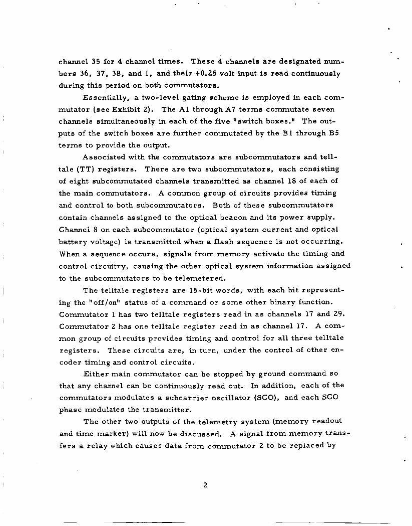
There a r e two commutators, but they a r e not redundant, since
they do not handle the same data.
onds per channel, o r approximately 24 seconds per frame. A common
group of circuits provides timing and control to both commutators ( see
Exhibit 1).
tuning fork oscillator.
The commutation rate i s 0.63 sec-
The timing and control signals a r e derived f r o m a 1,628-cps
The commutator switches, a s discussed below, a r e set up to pro-
vide 35 data channels, but 38 channels per commutator a r e actually transmitted. This is accomplished by flholdingff the channel following
channel 35 f o r 4 channel times.
bers 3 6 , 37, 38, and 1, and their t0.25 volt input is read continuously
during this period on both commutators.
These 4 channels a r e designated num-
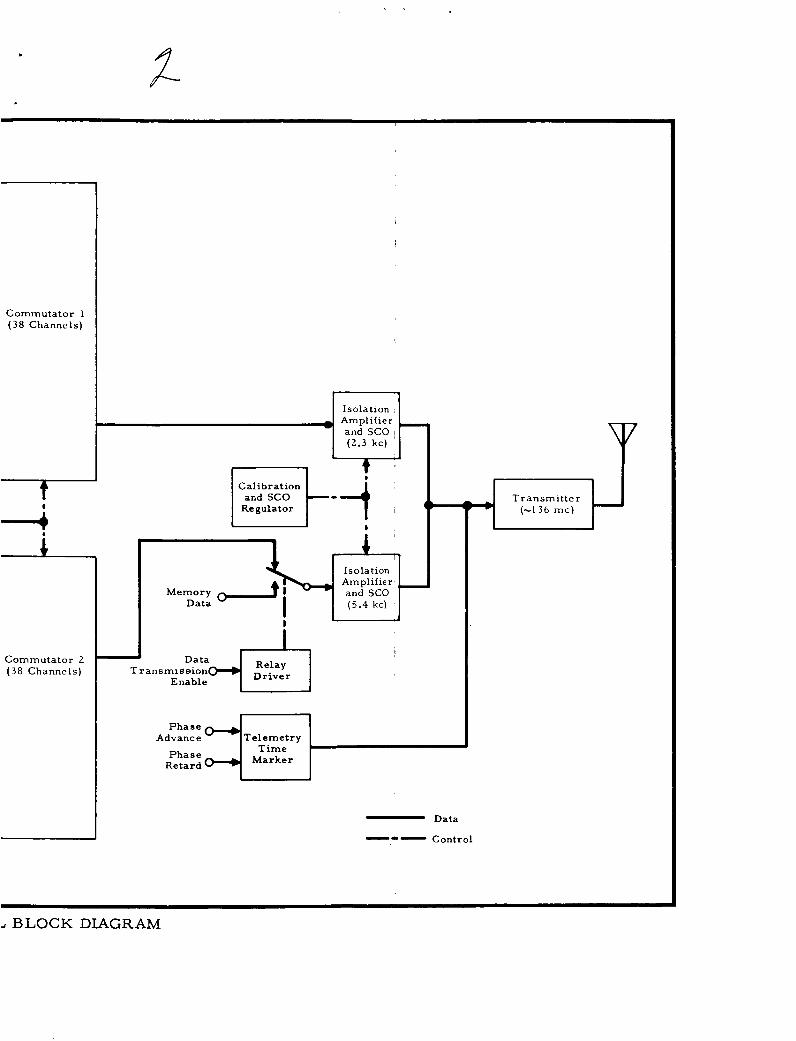
Essentially, a two-level gating scheme is employed in each com-
mutator (see Exhibit 2). The A1 through A7 t e rms commutate seven
channels simultaneously in each of the five "switch boxes." The out- puts of the switch boxes a r e further commutated by the B1 through B5 t e rms to provide the output.
Associated with the commutators a r e subcommutators and tell- ta le (TT) registers. There a r e two subcommutators, each consisting
of eight subcommutated channels transmitted as channel 18 of each of
the main commutators. A common group of circuits provides timing
and control to both subcommutators. Both of these subcommutators
contain channels assigned to the optical beacon and its power supply.
Channel 8 on each subcommutator (optical system current and optical
battery voltage) i s transmitted when a flash sequence is not occurring.
When a sequence occurs, signals f rom memory activate the timing and
control circuitry, causing the other optical system information a s signed
to the subcommutators to be telemetered.
The telltale regis ters a r e 15-bit words, with each bit represent- ing the "off/on" status of a command o r some other binary function.
Commutator 1 has two telltale regis ters read in as channels 17 and 29. Commutator 2 has one telltale register read in as channel 17. A com-
mon group of circuits provides timing and control for all three telltale registers. These circuits a re , in turn, under the control of other en- coder timing and control circuits.
Either main commutator can be stopped by ground command SO
that any channel can be continuously read out.
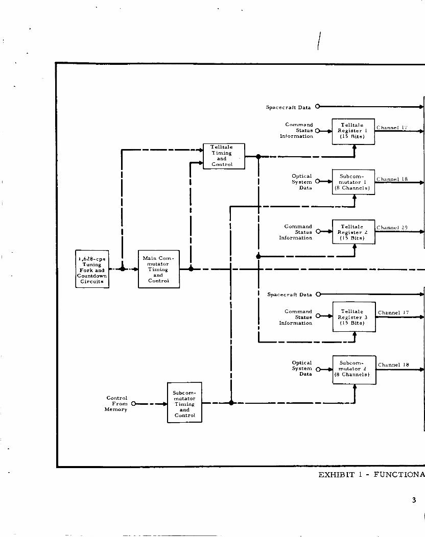
commutators modulates a subcarr ier oscillator (SCO), and each SCO phase modulates the transmitter.
In addition, each of the
The other two outputs of the telemetry system (memory readout
and time marker) wil l now be discussed.
f e r s a relay which causes data f rom cornmutator 2 to be replaced by
A signal f rom memory t rans-
2
Spacecraft Data 0 I
Register 1 ( 1 5 B i t s )
Command Status
Information
----- Timing
Control
Channel 18 Optical System mutator 1
Data (8 Channels) I
---.
r i
Information
I
i I
--- --- -- Countdown and
Circuits Control
I Spacecraft Data 0 I
Register 3 ( 1 5 B i t s )
Command Status
Information
Cor
I
mutator 2 (8 Channels)
Optical System
Data
Memory
Channel 18
EXHIBIT 1 - FUNCTIONA
3
I
I .
?-
Commutator 1 (38 Channels)
Isolation Amplifier and SCO ~
(2 .3 kc)
Calibration
Regulator L
Commutator 2 (38 Channels)
Amplifier and SCO
Relay Driver T ransmiseion
Enable
Telemetry Phase
Advance
I
Retard Phase 4 1- Data
-0- Control
Transmitter (-136 m c )
BLOCK DIAGRAM
Data
A1
Data
A2
Data
A3
Data
A4
Data
A5
Data
A6
Data
A7
1
Seven Data
Input.
Seven Data
Input 8
Seven Data
Input.
Seven Data
Input.
,--I
0 output
EXHIBIT 2 - LOGICAL REPRESENTATION O F COMMUTATOR
5
memory readout data at the input of the SCO. the relay transfers back.
vance and phase retard signals f rom the spacecraft clock to modulate
the transmitter directly.
When readout is complete,
The t ime marker circuits cause the phase ad-
The n o r m a l operational plan for the telemetry subsystem calls
for operation with only the t ransmit ter and time marker on.
mainder of the unit (commutated data and memory readout) will be turned
on only when the spacecraft is over a ground station assigned to receive
these data.
The re-
3 . Engineering Analysis
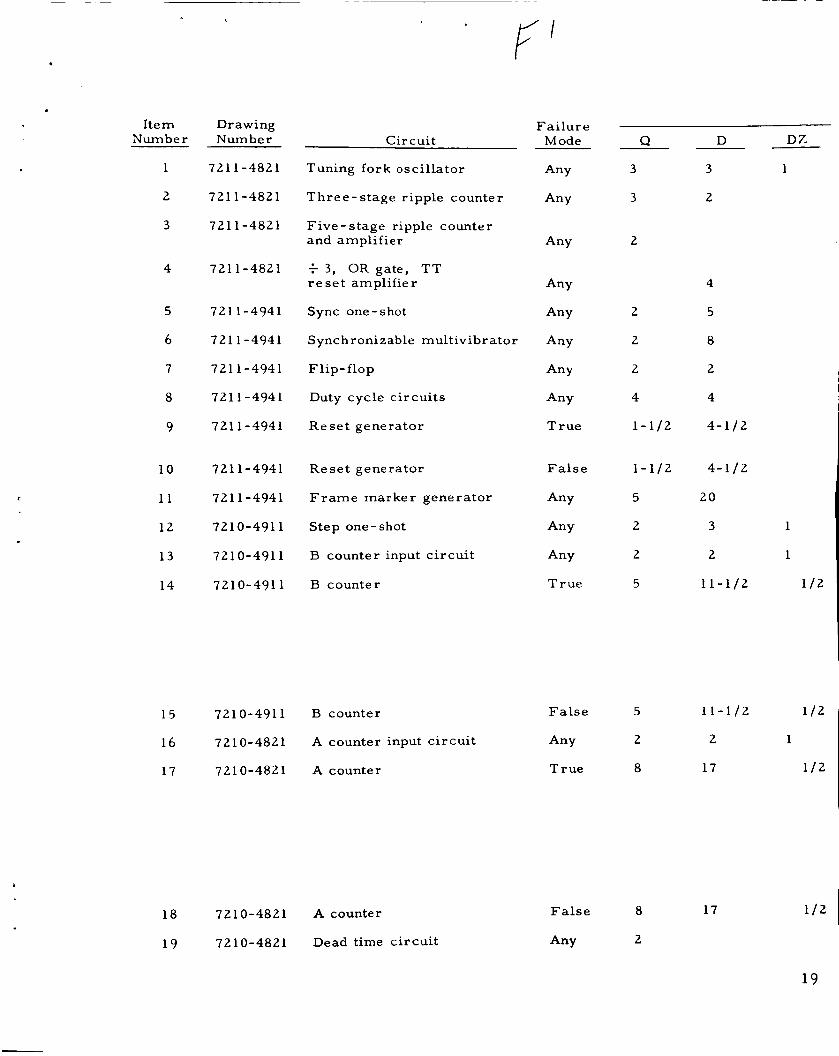
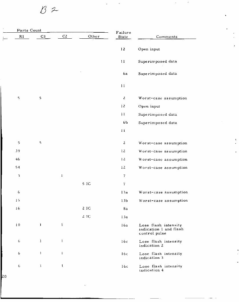
The appendix to this TAM contains the failure mode and ef-
fect analysis.
verity f r o m loss of the entire subsystem (due to loss of the transmitter)
to loss of one TT bit.
pected in a subsystem of this type) a r e summarized in Exhibit 3.
The analysis revealed 20 failure states, ranging in se-
These failure states (none of which were unex-
An important aspect of failures in a telemetry system is that ce r - tain types of failure states may occur and not be recognized f rom the
telemetry data. Attention was given to this potential problem, and a
discussion of it appears in Reference 1. Of the 20 possible failure
states in the GEOS telemetry subsystem, it was fe l t that very few were of this type. State 15 (the loss of one TT bit) would be the most diffi-
cult to identify via diagnosis of other spacecraft data and/or the re -
sponse of the spacecraft to commands.
4. Telemetrv Model
Making use of the preceding sections, the telemetry sub-
system may be thought of as providing 128 discrete ltoutputs" which
are either present o r absent, depending on the state of the subsystem.
The 128 outputs consist of the memory readout, the t ime marke r , 45 telltale bits (utilizing 3 main commutated channels), 16 subcommutated
channels (utilizing 2 main commutated channels), and, finally, 6 5 "other" main commutated channels.
function of i ts failed and unfailed components. The state of the subsystem is a
6
EXHIBIT 3 - FAILURE STATES
Failure State
1
2
3
4
5
6
7
8
9
10
11
12
13
14
15
16
17
18
19
20
Loss
All telemetry
Both commutators
60 channels (30 f rom each commutator)
56 channels (28 from each cornmutator)
Commutator 2 and memory readout
One commutator
Both subcommutator s
One subcommutator
All telltale registers
One telltale register
Seven comrnutated channels
One commutated channel
One subcommutated channel
Five telltale bits
One telltale bit
Flash intensity information
Memory readout
Time marker
Sync
T ernp e r atur e indications
7
c
Assume that the presence of all 128 outputs yields a value of unity for the subsystem. Further , assume that each output contrib-
utes a proportion, Vi , of this value independent of any other output
and that the value of any particular subsystem state is the s u m of the
values associated with each output.
the probability of output i being present, considered independently,
it can be shown that the telemetry subsystem figure of mer i t is given
Under these conditions, i f Pi is
by
128 1 PiVi . i= 1
Exhibit 4 explicitly defines all 128 outputs, as well as tabulating the
probability and relative value of each. Derivation of the probability
and value terms of Exhibit 4 is undertaken in the following two
subsections.
a. Derivation of Output Probabilities, Pi
The probability of any particular output being present,
at time t , is assumed to be given by an expression of the form
Pi = exp (-hit) ( 2)
where i = particular output
Xi = total failure rate of - all par ts required to achieve output i
t = operating time (uniformly assumed to be 8,7 60 hours)
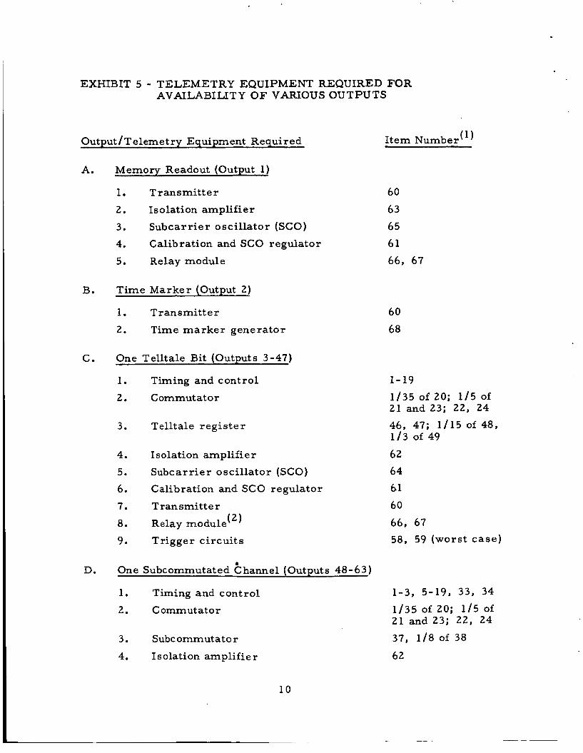
The Xi a r e derived by consulting Exhibit 5, which indicates generally
the portions of the telemetry subsystem required for each output and
which i s cross-referenced to the appendix (via the i tem numbers).
appendix gives a comprehensive tabulation of the telemetry component
The
8
EXHIBIT 4 - TELEMETRY MODEL TERMS
Output, Probability, Value , p; v:
1 0.855 31
2 0.825 2
3-32 0.246 119
33-47 0.244 119
48 - 52 0.323 1 /4
53-55 0.340 1 /4
56-63 0.336
64-71 0.377
72-95 0.408
96- 100 0.373
101-128 0.404
1 /4
58/65
58/65
58/65
58/65
OutDut Definition
Memory readout
Time marke r
Telltale bits f rom commutator 1 (30)
Telltale bits from commutator 2 (15)
Subcommutated channels f rom commutator 1 with flash inten- sity information (5)
Subcommutated channels from commutator 1 without flash intensity information (3)
Subcommutated channels from commutator 2 (8)
Commutated channels f rom commutator 1 with tempera- ture information (8)
Other commutated channels f rom commutator 1 (24)
Commutated channels f rom commutator 2 with tempera- tu re information (5)
Other commutated channels f rom commutator 2 (28)
128 2 P i V i = 0.54 i = l
9
EXHIBIT 5 - TELEMETRY EQUIPMENT REQUIRED FOR AVAILABILITY O F VARIOUS OUTPUTS
Output/Telemetry Equipment Required
A.
B.
C.
D.
Memory Readout (Output 1)
1. T r ansmit t e r
2. Isolation amplifier
3, Subcarrier oscillator (SCO)
4. Calibration and SCO regulator
5. Relay module
Time Marker (Output 2)
1. Trans mitt e r
2. Time marker generator
One Telltale Bit (Outputs 3-47)
1. Timing and control
2. Commutator
3. Telltale regis ter
4. Isolation amplifier
5. Subcarrier oscil lator (SCO)
6. Calibration and SCO regulator
7. Transmitter 8. Relay module (2)
9. Trigger c i rcui ts
One Subcommutated thannel (Outputs 48-63)
1. Timing and control
2. Commutator
3. Subcommutator
4. Isolation amplifier
(1 1 Item Number
60 63 65 61 66, 67
60 68
1- 19 1/35 of 20; 1/5 of 21 and 23; 22, 24 46, 47; 1/15 of 48, 1/3 of 49 62 64 61 60 66, 67 58, 59 (worst case)
1-3, 5-19, 33, 34 1/35 of 20; 1/5 of 21 and 23; 22, 24 37, 1/8 of 38
62
10
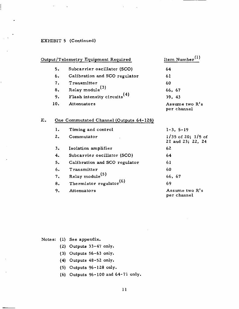
EXHIBIT 5 (Continued)
Output / T el e met r y Equipment Requi r ed Item Number (1)
erence 2. being present a r e tabulated in Exhibit 4.
Component part failure ra tes a r e as given previously in Ref-
The numerical results for the probability of each output
b. Derivation of Output Relative Values, V i
In order to derive a rational assignment of relative
values to each state, assume f i r s t that each main commutated channel
has a value of unity. Then, since the 16 subcommutated channels uti-
lize 2 main commutated channels, assign a value of 1 /8 to each sub-
commutated channel. The 45 telltale bits utilize 3 main commutated
channels, and, hence, each bit may be assigned a value of 1/15. The
memory readout essentially replaces one commutator when it i s in
service; thus, assign it a value of 35. There is no direct relationship
between the time marker and a main commutated channel, but a value
of 2 i s judged to be reasonable in the present context. If these values
a r e normalized to total unity, the Vi shown in Exhibit 4 a r e the result.
If the operation of Equation (1) is performed using the data of Exhibit 4, the telemetry subsystem figure of mer i t is found to be ap-
proximately 0.54. A cursory examination of Exhibit 4 indicates that
the memory readout alone contributes nearly half of the subsystem
figure of merit. Since the probability associated with this output i s
relatively high, reducing the relative value of the memory readout will
reduce the telemetry subsystem figure of mer i t , and vice versa.
5. Results
The design and implementation of the telemetry subsystem
a r e considered by P R C to be good.
mit experiment results on GEOS, it i s felt that the nonredundant design i s adequate.
Since telemetry i s not used to t rans-
The telemetry subsystem figure of mer i t of 0.54 (indicating
roughly that the subsystem is expected to be 54-percent available at the end of one year) i s judged to be not unreasonable in view of the gen-
erally pessimistic assumptions used throughout the GEOS subsystem
assessments .
values a s signed to the individual outputs. The figure of mer i t i s highly dependent on the relative
12
6 . Summary
a. The design and implementation of the GEOS telemetry subsystem are good.
The expected proportion of telemetry subsystem capability available at the end of one year is approxi- mately 5 4 percent.
b.
1 3
. I
REFERENCES
1 . Operational Reliability Assessment of the GEOS A Spacecraft, Technical Advisement Memorandum No. 106- 10 (PRC D- 1056 1, 29 October 1965.
2. Component Part Failure Rate Assignments for Reliability As- sessment of the GEOS Satellite, Technical Advisement Memo- randum No. 106-6 (PRC D-1027), 8 June 1965.
1 5
APPENDIX
FAILURE MODE AND EFFECT ANALYSIS
f
I tem Number
1
2
3
4
5
6
7
8
9
10
11
12
13
14
Drawing Number
72 1 1 -482 1
721 1-4821
721 1-4821
7211-4821
721 1-4941
721 1-4941
721 1-4941
721 1-4941
721 1-4941
721 1-4941
7211-4941
7210-491 1
7210-491 1
7210-491 1
Ci rcu i t
Tuning fork osci l la tor
T h r e e - s tage r ipple counter
F ive - s t age ripple counter and amplif ier
t 3, O R gate, T T r e s e t amplif ier
Sync one -shot
Synchronizable mul t iv ibra tor
F l ip- f lop
Duty cycle c i rcu i t s
Re set gene r a t o r
R e s e t genera tor
F r a m e m a r k e r genera tor
S tep one- shot
B counter input c i r cu i t
B counter
15 7210-4911 B counter
16 7210-4821 A counter input c i r cu i t
17 7210-4821 A counter
18 7210-4821 A counter
19 7210-4821 Dead time c i r cu i t
Q
3
3
2
2
2
2
4
1-112
1-112
5
2
2
5
DZ I D
3 1
2
4
5
8
2
4 I
4-112
4-112
20
3 1
2 1
11-112 112
F a l s e 5
Any 2
T r u e 8
False 8
Any 2
11-112 112
2 1
17 112
17
19
Parts Count
R1
9
6
5
5
6
11
8
10
5- 1 1 2
5-112
26
5
6
10-112
10-112
6
16
16
2
c1
1
3
3
2
5
4
1
1
1
10
2
1
2-112
2 - 112
1
4
4
1
C2 Other
6 1 tuning fork
1 2 IC
5 IC
3 IC
Fai lure State
2
2
2
'9
~2
'2
2
2
2
I
19
2
2
2
2
4
2
2
3
2
Comments
Assumes fai lure holds timing c i r cu i t s r e s e t
Indeterminate
Wors t -case assumption
If counter fa i l s so that e i ther no outputs a r e t r u e o r m o r e than one output i s t rue , all encoded data a r e lost; i f counter fails so that only one output is t rue , then i t s data groups w i l l be con- tinuous ly t e l eme te r ed
(See above comment)
If counter fails so that e i ther no outputs a r e t rue o r m o r e than one output is t rue , all encoded data a r e lost ; if counter fa i l s so that only one output is t rue , then one channel f rom each data group will be continuously t e l eme te red
(See above comment)
Item Number
2 0
21
2 2
2 3
2 4
2 5
26
27
2 8
29
3 0
31
32
3 3
34
35
36
37
38
39
4 0
4 I
4 2
Drawing Number
721 0-4761
7210-4761
7 2 1 0 - 4 7 6 1
721 0 - 4 7 6 1
7210-4761
721 0 - 4 7 6 1
7 21 0 - 4 7 6 1
7 2 1 0 - 4 7 6 1
7 2 1 0 - 4 7 6 1
7 2 1 0 - 4 7 6 1
7 2 1 0 - 4 7 4 1
7210-471 1
7210-4731
7211-4741
7 2 1 1 - 4 7 4 1
7 2 1 1-4741
721 1-4741
721 1-4721
7L11-4721
721 1-4761
7 2 1 1-4761
721 1-4761
7 2 I 1 - 4 7 6 I
Fa i lure Circuit Mode
Commutator 1 (five data groups of seven channels each)
Commutator 1 (five data groups of seven channels each)
Commutator 1 (five data groups of seven channels each)
Commutator 1 (five data groups of seven channels each)
Commutator 1 (five data groups of seven channels each)
Commutator 2
Commutator 2
Commutator 2
Commutator 2
Commutator 2
Attenuators, commutator
Attenuators, commutator
A tte nua t o r s , c om m uta tor
Sub c o III HI ut at o r reg ulat o r Any
Subcommutator control Any
Attenuators, subcommutator 1
Attenuators, subcommutator 2
Subcommutator 1
Subcommutator 1
Light intensity de tec tors
Light intensity de tec tors
Light intcnsity de tec tors
Light intensity detectors
1
1 2
1 2
1 L
2
P a r t s Count i Failure
R1 c 1 c2 Other State Comments 7-
12 Open input
I 11 Superimposed data
6a Supe r imp0 sed data
11
5
5
1
5 IC
2 IC
L IC
1 1
2 Worst-case as sumption
12 Open input
1 1 Superimposed data
6b Superimposed data
1 1
2 W o r s t - case a s sumpt ion
1 2 Worst- case as sumption
1 2 Worst-case assumption
1 2 Worst-case assumption
7
7
1 3 a Worst-case assumption
13b Worst-case as sumption
8a
13a
16a Lose flash intensity indication 1 and flash control pulse