1 | Page PRE-FEASIBILITY REPORT FOR THE PROPOSED EXPANSION OF EXISTING INTEGRATED SPONGE IRON PLANT, STEEL MELTING SHOP (INDUCTION FURNACE) WITH CAPTIVE POWER PLANT CAPACITY: STEEL BILLETS FROM 216000 MTPA TO 330000 MTPA SPONGE IRON FROM 198000 MTPA TO 297000 MTPA CAPTIVE POWER FROM 24.0 MW TO 53.0 MW AT PLOT NO. AL – 5, SECTOR NO. 23, GIDA INDUSTRIAL ESTATE, VILL- SAHBAJGANJ & DOMHARMAPHITEHSIL – SAHAJANWA DISTRICT- GORAKHPUR (U.P) PIN - 273209 BY GALLANTT ISPAT LIMITED
Transcript
1 | P a g e
PRE-FEASIBILITY REPORT
FOR
THE PROPOSED
EXPANSION OF EXISTING INTEGRATED SPONGE IRON PLANT, STEEL
MELTING SHOP (INDUCTION FURNACE) WITH CAPTIVE POWER PLANT
Steel is a basic commodity for all industrial activities.
Quantum of its consumption is considered as an index of
industrial prosperity. Since independence, there has been
substantial growth. From 1.5 Mt in 1950-51, India‟s
steelmaking capacity has increased to about 43 Million
Tons/year at present. In spite of such a growth, the per capita
steel consumption in India continues to remain at a low level
of around 20 Kg only, as compared to 110 kg as compared to
global average. India‟s economy is also posed for sharp
upturn. This is expected to lead, to a substantial improvement
in the per capita consumption of steel. Further, while India is
endowed with rich deposits of raw materials and its labour
rate continues to be cheap on international basis, its
contribution with 20% of world population is only of the order
of 2.6% of world steel production. Therefore, under the current
liberalized economy, private entrepreneurs can avail of the
favourable situation for investment in the steel industry of the
country.
The Company has selected modified IF route for steel making.
This route of steel making has the benefits of lower per ton
investment, appropriate for small steel plant, lower power
consumption and environment friendly process in comparison
3 | P a g e
Contents Details
to other processes of steel making.
During 2008-09, it is estimated that 1074 units with a
capacity of 22.18 million tonne were in operation. The total
production of induction furnace units registered a growth of
6.62% during 2008-09, producing 18.05 million tonne against
a production of 16.93 million tonne in 2007-08.
India was the fifth largest producer of crude steel in the world
in 2009, based on rankings released by World Steel
Association. Domestic crude steel production grew at a
compounded annual growth rate of 8.6 per cent during 2004-
05 to 2008-09. This growth was driven by both capacity
expansion (from 47.99 million tonne in 2004-05 to 66.343
million tonne in 2008-09) and improved capacity utilisation.
India, the world's largest producer of direct reduced iron (DRI)
or sponge iron, is also expected to maintain its lead in the near
future. Sponge iron production grew at a CAGR of 11 per cent
to reach a level of 21.09 million tonne in 2008-09 compared to
12.54 million tonne in 2004-05. India is expected to become
the second largest producer of steel in the world by 2018-19,
provided all requirements for fresh capacity creation are met.
Indian steel industry has just come out of the slowdown that
affected its performance during 2008-09. Domestically, 2009
ended on a relatively better and encouraging note, with CSO
reporting an overall improvement of economic situation
through its GDP data, which showed a robust 7.9 per cent
growth during July-September 2009-10. IIP too had registered
a strong 7.6 per cent growth during April-November 2009-10,
further bolstering the idea that the demand side is back on
stable footing. For steel, this is of key importance and the
growth rates registered for leading end-use segments like
manufacturing, consumer durables, construction, the stable
growth of the service sector and agriculture sector spell good
news. April-December 2009 provisional data released by JPC
indicates a 7.8 per cent rise in consumption of total finished
steel. Globally also there are signs of improvement in economic
conditions and firming up of demand and prices.
4 | P a g e
Contents Details
i.Identification of project
and project proponent.
In case of mining
project, a copy of
mining lease/letter of
intent should be given.
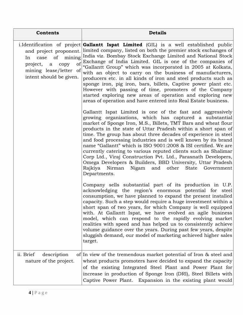
Gallantt Ispat Limited (GIL) is a well established public limited company, listed on both the premier stock exchanges of India viz. Bombay Stock Exchange Limited and National Stock
Exchange of India Limited. GIL is one of the companies of “Gallantt Group” which was incorporated in 2005 at Kolkata,
with an object to carry on the business of manufacturers, producers etc. in all kinds of iron and steel products such as sponge iron, pig iron, bars, billets, Captive power plant etc.
However with passing of time, promoters of the Company started exploring new areas of operation and exploring new areas of operation and have entered into Real Estate business.
Gallantt Ispat Limited is one of the fast and aggressively
growing organizations, which has captured a substantial market of Sponge Iron, M.S., Billets, TMT Bars and wheat flour products in the state of Uttar Pradesh within a short span of
time. The group has about three decades of experience in steel and food processing industries and is well known by its brand
name “Gallantt” which is ISO 9001:2008 & ISI certified. We are currently catering to various reputed clients such as Shalimar Corp Ltd., Viraj Construction Pvt. Ltd., Parasnath Developers,
Omega Developers & Builders, BBD University, Uttar Pradesh Rajkiya Nirman Nigam and other State Government Departments.
Company sells substantial part of its production in U.P.
acknowledging the region‟s enormous potential for steel consumption, we have planned to expand the present installed capacity. Such a step would require a huge investment within a
short span of two years, for which Company is well equipped with. At Gallantt Ispat, we have evolved an agile business
model, which can respond to the rapidly evolving market realities with speed and has helped us to consistently achieve volume guidance over the years. During past few years, despite
sluggish demand, our model of marketing achieved higher sales target.
ii. Brief description of
nature of the project.
In view of the tremendous market potential of Iron & steel and
wheat products promoters have decided to expand the capacity
of the existing Integrated Steel Plant and Power Plant for
increase in production of Sponge Iron (DRI), Steel Billets with
Captive Power Plant. Expansion in the existing plant would
5 | P a g e
Contents Details
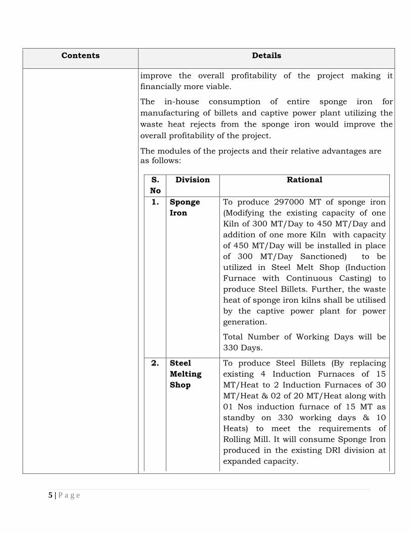
improve the overall profitability of the project making it
financially more viable.
The in-house consumption of entire sponge iron for
manufacturing of billets and captive power plant utilizing the
waste heat rejects from the sponge iron would improve the
overall profitability of the project.
The modules of the projects and their relative advantages are as follows:
S.
No
Division Rational
1. Sponge
Iron
To produce 297000 MT of sponge iron
(Modifying the existing capacity of one
Kiln of 300 MT/Day to 450 MT/Day and
addition of one more Kiln with capacity
of 450 MT/Day will be installed in place
of 300 MT/Day Sanctioned) to be
utilized in Steel Melt Shop (Induction
Furnace with Continuous Casting) to
produce Steel Billets. Further, the waste
heat of sponge iron kilns shall be utilised
by the captive power plant for power
generation.
Total Number of Working Days will be
330 Days.
2. Steel
Melting
Shop
To produce Steel Billets (By replacing
existing 4 Induction Furnaces of 15
MT/Heat to 2 Induction Furnaces of 30
MT/Heat & 02 of 20 MT/Heat along with
01 Nos induction furnace of 15 MT as
standby on 330 working days & 10
Heats) to meet the requirements of
Rolling Mill. It will consume Sponge Iron
produced in the existing DRI division at
expanded capacity.
6 | P a g e
Contents Details
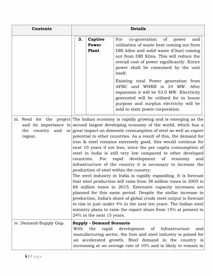
3. Captive
Power
Plant
For co-generation of power and
utilization of waste heat coming out from
DRI kilns and solid waste (Char) coming
out from DRI Kilns. This will reduce the
overall cost of power significantly. Entire
power shall be consumed by the unit
itself.
Existing total Power generation from
AFBC and WHRB is 24 MW. After
expansion it will be 53.0 MW. Electricity
generated will be utilised for in house
purpose and surplus electricity will be
sold to state power corporation.
iii. Need for the project
and its importance to
the country and or
region.
The Indian economy is rapidly growing and is emerging as the
second largest developing economy of the world, which has a
great impact on domestic consumption of steel as well as export
potential to other countries. As a result of this, the demand for
iron & steel remains extremely good, this would continue for
next 10 years if not less, since the per capita consumption of
steel in India is still very low compared to other developed
countries. For rapid development of economy and
infrastructure of the country it is necessary to increase the
production of steel within the country.
The steel industry in India is rapidly expanding. It is forecast
that steel production will raise from 38 million tones in 2005 to
68 million tones in 2015. Extensive capacity increases are
planned for this same period. Despite the stellar increase in
production, India‟s share of global crude steel output is forecast
to rise to just under 4% in the next ten years. The Indian steel
ministry plans to raise the export share from 15% at present to
24% in the next 15 years.
iv. Demand-Supply Gap. Supply - Demand Scenario
With the rapid development of Infrastructure and
manufacturing sector, the Iron and steel industry is poised for
an accelerated growth. Steel demand in the country is
increasing at an average rate of 10% and is likely to remain in
7 | P a g e
Contents Details
10-12% range at least for the next decade. In order to meet the
steadily growing steel demand in the country, domestic steel
producing capacity is required to be higher than 110 MTPA
within next three years and, 150 MTPA by the year 2018-19.
Indian economy is growing at more than 10% rate, steel
demand and supply will grow in the same way. As good quality
iron ore deposits are depleting fast beneficiation technologies
will have to be adopted to meet iron ore demand. Therefore
good yield of beneficiation process generally around 70 % will
make this technology economically viable.
v. Imports vs. Indigenous
production.
Only indigenous production.
vi. Export Possibility. No
vii. Domestic/export
Markets.
Domestic Only
viii. Employment Generation
(Direct and Indirect)
due to the project.
Direct employment :- for expansion additional 140 Persons
will be required. Total Number of manpower after expansion
will be 396 No.s.
Indirect employment :- approx 500 persons
3. Project Description
i. Type of project
including interlinked
and interdependent
projects, if any.
Category „A‟ schedule in 3(a),
Expansion of existing Sponge iron plant (DRI), Steel Melting
shop (Induction furnace) with Captive power plant.
ii. Location (map showing
general location,
specific location, and
project boundary &
project site layout) with
coordinates.
Location map Enclosed (Google EARTH MAP),
iii. Details of alternate
sites considered and the
basis of selecting the
proposed site,
Expansion will be done within existing premises.
8 | P a g e
Contents Details
particularly the
environmental
considerations gone into
should be highlighted.
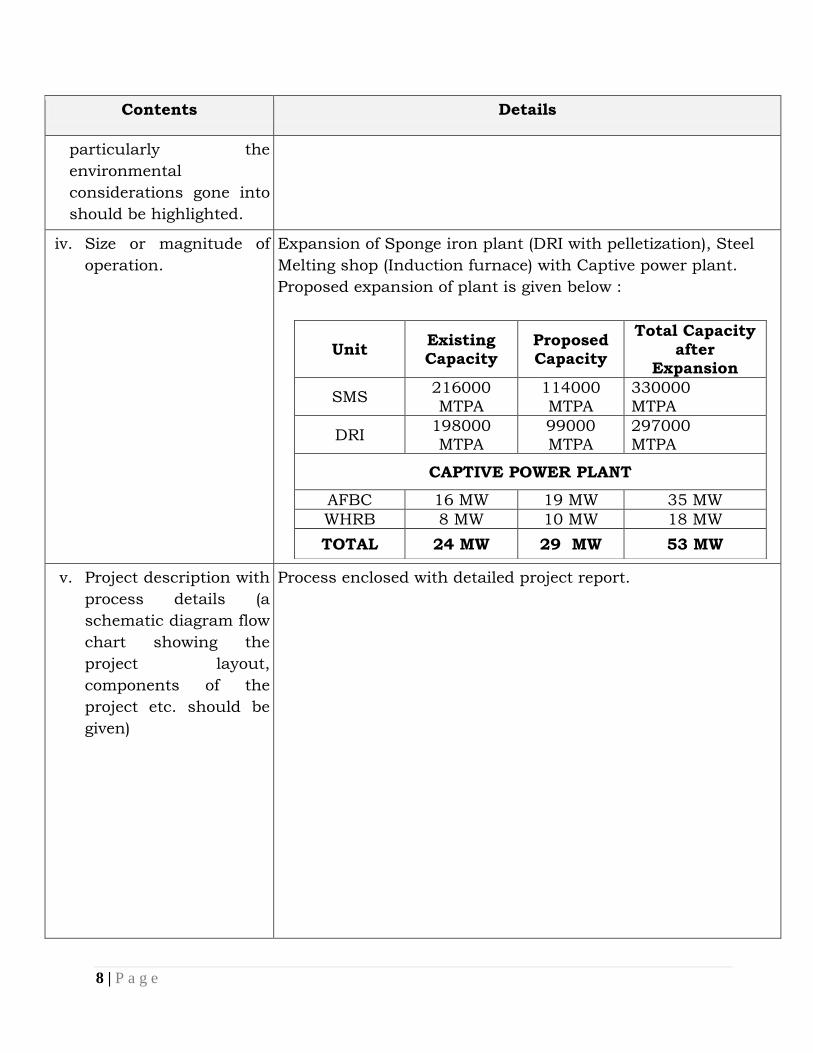
iv. Size or magnitude of
operation.
Expansion of Sponge iron plant (DRI with pelletization), Steel
Melting shop (Induction furnace) with Captive power plant.
Proposed expansion of plant is given below :
Unit Existing Capacity
Proposed Capacity
Total Capacity
after Expansion
SMS 216000 MTPA
114000 MTPA
330000 MTPA
DRI 198000 MTPA
99000 MTPA
297000 MTPA
CAPTIVE POWER PLANT
AFBC 16 MW 19 MW 35 MW
WHRB 8 MW 10 MW 18 MW
TOTAL 24 MW 29 MW 53 MW
v. Project description with
process details (a
schematic diagram flow
chart showing the
project layout,
components of the
project etc. should be
given)
Process enclosed with detailed project report.
9 | P a g e
Contents Details
vi. Raw material required
along with estimated
quantity, likely
source, marketing
area of final products,
Mode of transport of
raw Material and
Finished Product.
Sr.
No. Material
Existing
Consumption
Total
Consumption
after
expansion Source
Sponge Iron Plant
1 Iron Ore 198000 MTPA 237600 MTPA Open Market
2 Pellets 158400 MTPA 237600 MTPA
Self / From
Manufacturer
3 Coal 198000 MTPA 267300 MTPA
Import/
auction
4 Dolomite 9900 MTPA 14850 MTPA Open Market
Steel Melt Shop Division
(Induction Furnace with Continues Caster)
1
Sponge
Iron 198000 MTPA 297000 MTPA Self
2
MS
Scraps 72845 MTPA 109267 MTPA Open market
3
Ferro
Alloy 3240 4950 Open Market
Captive power Plant (AFBC)
1 Coal 38016 MTPA 124740 MTPA Auction
2
Rice
Husk 12672 MTPA 83160 MTPA Open Market
3 Dolochar 26038 MTPA 41580 MTPA Self
vii. Resource
optimization/recycling
and reuse envisaged in
the project, if any,
should be briefly
outlined.
Water :
As this project is based on Zero Discharge, 100 % recycling of
water will be done in the process.
Solid waste:
Dolochar (126 TPD) will be reused as raw material within the plant for power generation through AFBC boiler.
Slag (108 TPD) will be used in filling of Low lying area and
10 | P a g e
Contents Details
in Road Making.
Total ash (226.0 TPD) from the Boiler and APCS Will be sold to brick manufacturing unit or used as binding
material for land filling.
viii. Availability of water its
source, Energy/power
requirement and
source should be given.
Existing Industry is present in Non Notified “Safe” Zone as
per CGWA. Water requirement met through existing tube
well.
Existing water requirement-
Industrial use: 1680 M3/Day
Domestic Use: 20M3/Day
Expansion Water requirement
Industrial use: 1540 M3/Day
Total Water Requirement after expansion -
Industrial use: 3220 M3/Day
Domestic Use: 20 M3/Day
Total Water requirement after expansion : 3240 M3/Day
ix. Quantity of wastes to
be generated (liquid
and solid) and scheme
for their Management/
disposal.
Liquid effluents- Proposed project is based on ZERO
discharge. Waste water generated from the process will be
treated in neutrilisation pit and After treatment 100 %
recycling will be done.
Solid Waste (after expansion)-
Dolochar (126 TPD) Will be reused as raw material within the plant for power generation through AFBC boiler.
Slag (108TPD) will be used in filling of Low lying area and in Road Making.
Total ash (226 TPD) from the Boiler and APCS Will be sold to brick manufacturing unit or used as binding material for
land filling.
x. Schematic
representations of the
feasibility drawing
which give information
of EIA purpose.
It will be enclosed in DPR/EIA report.
11 | P a g e
Contents Details
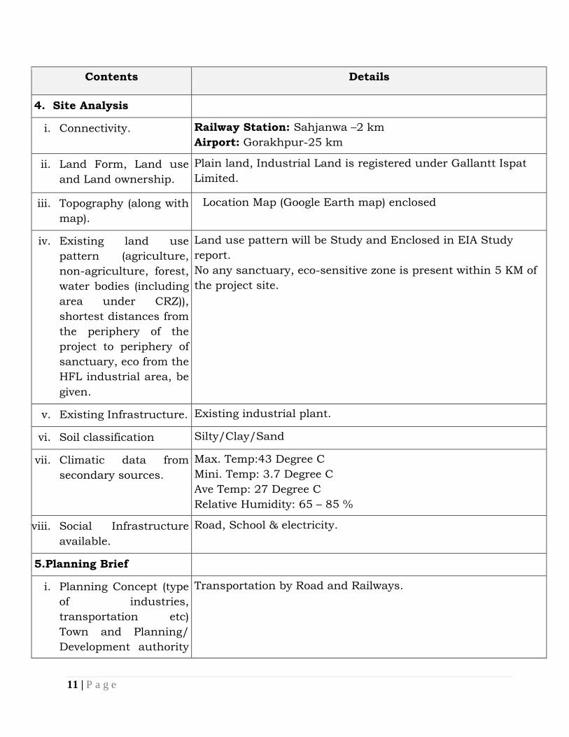
4. Site Analysis
i. Connectivity. Railway Station: Sahjanwa –2 km
Airport: Gorakhpur-25 km
ii. Land Form, Land use
and Land ownership.
Plain land, Industrial Land is registered under Gallantt Ispat
Limited.
iii. Topography (along with
map).
Location Map (Google Earth map) enclosed
iv. Existing land use
pattern (agriculture,
non-agriculture, forest,
water bodies (including
area under CRZ)),
shortest distances from
the periphery of the
project to periphery of
sanctuary, eco from the
HFL industrial area, be
given.
Land use pattern will be Study and Enclosed in EIA Study
report.
No any sanctuary, eco-sensitive zone is present within 5 KM of
the project site.
v. Existing Infrastructure. Existing industrial plant.
vi. Soil classification Silty/Clay/Sand
vii. Climatic data from
secondary sources.
Max. Temp:43 Degree C
Mini. Temp: 3.7 Degree C
Ave Temp: 27 Degree C
Relative Humidity: 65 – 85 %
viii. Social Infrastructure
available.
Road, School & electricity.
5.Planning Brief
i. Planning Concept (type
of industries,
transportation etc)
Town and Planning/
Development authority
Transportation by Road and Railways.
12 | P a g e
Contents Details
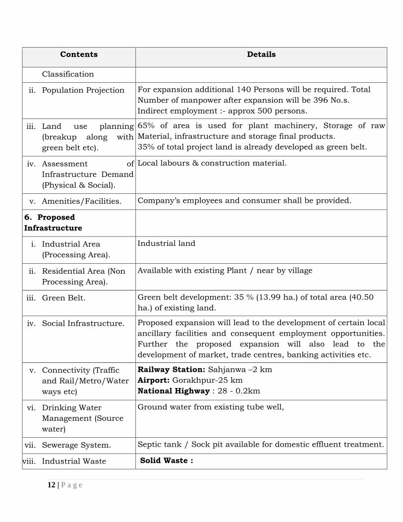
Classification
ii. Population Projection For expansion additional 140 Persons will be required. Total
Number of manpower after expansion will be 396 No.s.
Indirect employment :- approx 500 persons.
iii. Land use planning
(breakup along with
green belt etc).
65% of area is used for plant machinery, Storage of raw
Material, infrastructure and storage final products.
35% of total project land is already developed as green belt.
iv. Assessment of
Infrastructure Demand
(Physical & Social).
Local labours & construction material.
v. Amenities/Facilities. Company‟s employees and consumer shall be provided.
6. Proposed
Infrastructure
i. Industrial Area
(Processing Area).
Industrial land
ii. Residential Area (Non
Processing Area).
Available with existing Plant / near by village
iii. Green Belt. Green belt development: 35 % (13.99 ha.) of total area (40.50
ha.) of existing land.
iv. Social Infrastructure. Proposed expansion will lead to the development of certain local
ancillary facilities and consequent employment opportunities.
Further the proposed expansion will also lead to the
development of market, trade centres, banking activities etc.
v. Connectivity (Traffic
and Rail/Metro/Water
ways etc)
Railway Station: Sahjanwa –2 km
Airport: Gorakhpur-25 km
National Highway : 28 - 0.2km
vi. Drinking Water
Management (Source
water)
Ground water from existing tube well,
vii. Sewerage System. Septic tank / Sock pit available for domestic effluent treatment.
viii. Industrial Waste Solid Waste :
13 | P a g e
Contents Details
Management. Dolochar (126 TPD) Will be reused as raw material within the plant for power generation through AFBC boiler.
Slag (108 TPD) will be used in filling of Low lying area and in Road Making.
Total ash (226 TPD) from the Boiler and APCS will be sold to brick manufacturing unit or used as binding material for land filling.
Hazardous Waste Spent oil, Used oil and oily waste shall be provided to
authorized recyclers/ reprocessors.
ix. Solid Waste
Management.
Dolochar will be reused as raw material within the plant for power generation through AFBC boiler.
Slag will be used in filling of Low lying area and in Road Making.
Total ash from the Boiler and APCS Will be sold to brick
manufacturing unit or used as binding material for land
filling.
x. Power Requirement &
Supply / source.
Power requirement 45 – 48 MW after Expansion. The above
demand will be met from own Captive power plant.
DG Set for power backup of auxiliary load.
DG sets Details :
(1 No) 1250 KVA (Existing)
(1 No) 1000 KVA (Existing)
(1 No) 630 KVA (Existing)
(1 No) 380 KVA (Existing)
(02Nos ) 1250 KVA (Proposed)
7. Rehabilitation and
Resettlement (R&R) Plan
i. Policy to be adopted
(Central/State) in
respect Of the project
affected persons
including home
oustees, land oustees
and landless laborers
(a brief outline to be
No R & R
14 | P a g e
Contents Details
given).
8. Project Schedule &
Cost Estimates
ii. Likely date of start of
construction and likely
date of completion
(Time schedule for the
project to be given).
After receipt of NOC & Environmental Clearance.
iii. Estimated project cost
along with analysis in
terms of economic
viability of the project.
Rs 201.93 Crores
iv. Cost toward
Environment
Protection
Rs 400.00 Lakh
9. Analysis of proposal
(Final Recommendations)
i. Financial and social
benefits with special
emphasis on the benefit
to the local people
including tribal
population, if any, in
the area.
Financial Benefits:
Benefits and advantages of expansion of existing plant:
a) It will full fill the Demand Supply Gap.
b) It is help in increment of Life style of Local People By
providing Jobs.
Social Benefits:
Greater employment for local populations
Environmental benefits:
a) Low emission of air pollutant (ESP installed) .
b) It is a Brown field project.
c) No waste water will be generated and 100 % recycling will
be done.
Other Benefits:
Revenues to the State and Central ex-chequers.
15 | P a g e
Contents Details
Over all development of District- Gorakhpur in particular and
Uttar Pradesh State in general.
16 | P a g e
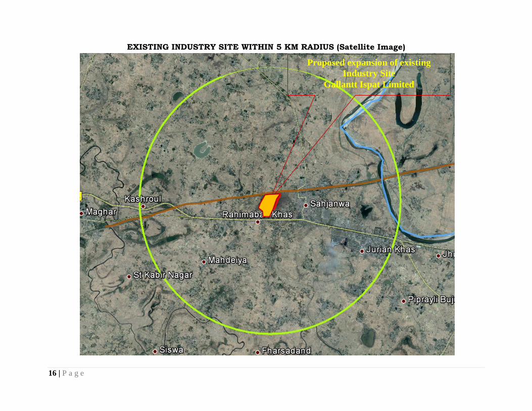
EXISTING INDUSTRY SITE WITHIN 5 KM RADIUS (Satellite Image)
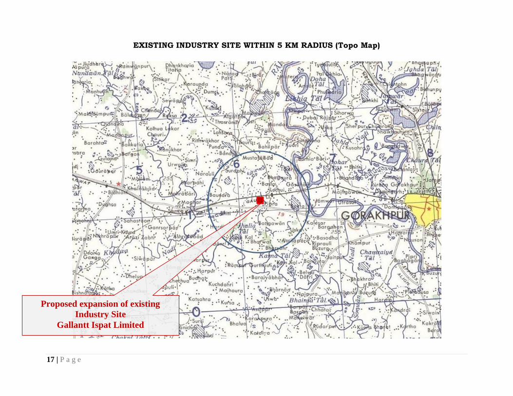
Proposed expansion of existing
Industry Site
Gallantt Ispat Limited
17 | P a g e
EXISTING INDUSTRY SITE WITHIN 5 KM RADIUS (Topo Map)
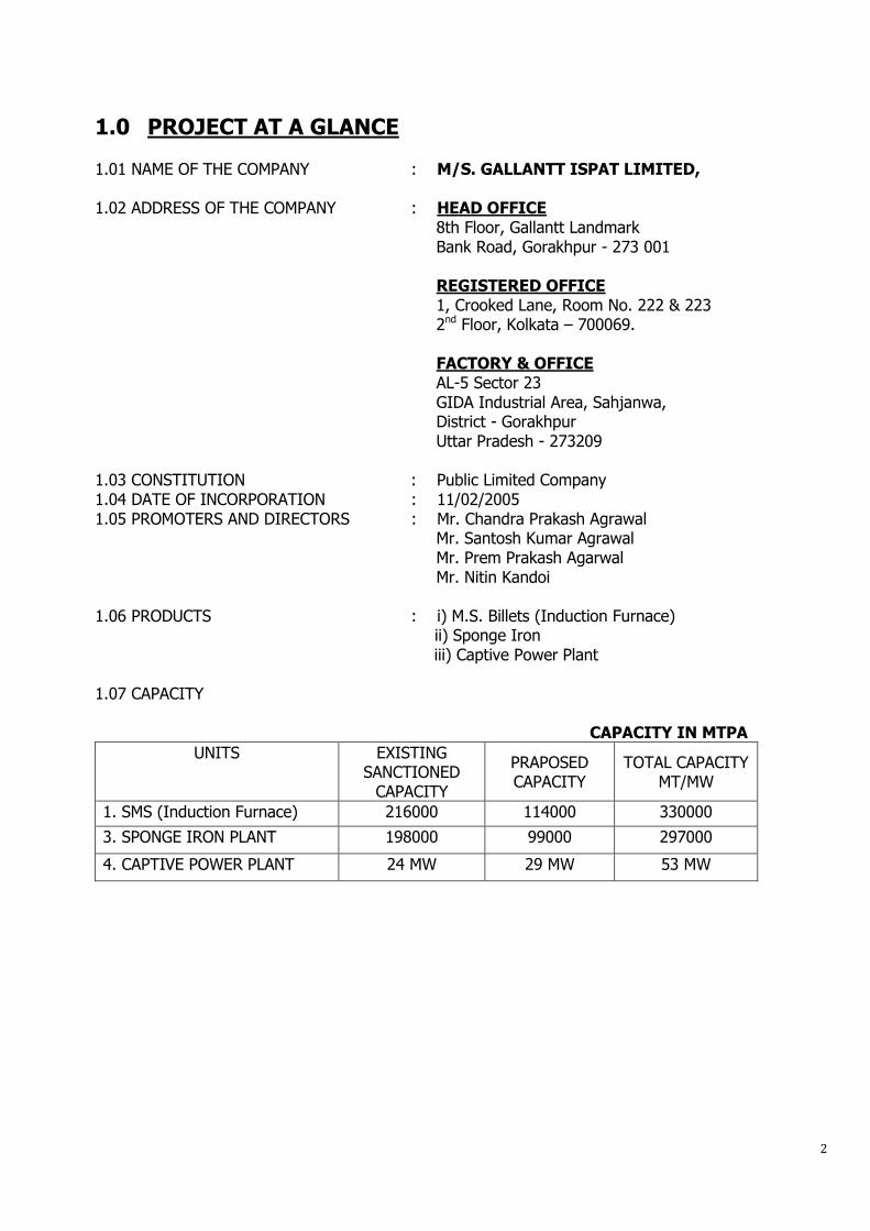
1.0 PROJECT AT A GLANCE 1.01 NAME OF THE COMPANY : M/S. GALLANTT ISPAT LIMITED, 1.02 ADDRESS OF THE COMPANY : HEAD OFFICE 8th Floor, Gallantt Landmark Bank Road, Gorakhpur - 273 001 REGISTERED OFFICE 1, Crooked Lane, Room No. 222 & 223 2nd Floor, Kolkata – 700069.
FACTORY & OFFICE AL-5 Sector 23
GIDA Industrial Area, Sahjanwa, District - Gorakhpur Uttar Pradesh - 273209 1.03 CONSTITUTION : Public Limited Company 1.04 DATE OF INCORPORATION : 11/02/2005 1.05 PROMOTERS AND DIRECTORS : Mr. Chandra Prakash Agrawal Mr. Santosh Kumar Agrawal
Mr. Prem Prakash Agarwal Mr. Nitin Kandoi
1.06 PRODUCTS : i) M.S. Billets (Induction Furnace) ii) Sponge Iron iii) Captive Power Plant 1.07 CAPACITY CAPACITY IN MTPA
UNITS
EXISTING SANCTIONED
CAPACITY
PRAPOSED CAPACITY
TOTAL CAPACITY MT/MW
1. SMS (Induction Furnace) 216000 114000 330000
3. SPONGE IRON PLANT 198000 99000 297000
4. CAPTIVE POWER PLANT 24 MW 29 MW 53 MW
PROJECT COST :
(Rs. In Cr)
SL.NO. PARTICULARS SMS DRI CPP MFA Total
1) LAND AND SITE DEVELOPMENT 0.00 0.00 0.00 0.00
2) CIVIL WORK & BUILDING 10.00 14.00 14.00 6.00 52.00
3) PLANT AND MACHINERY 29.40 28.23 88.50 11.80 157.93
4) MISCELLANEOUS FIXED ASSETS 0.00 0.00 0.00 0.00
6) CONTINGENCIES 0.00 0.00 0.00 0.00
TOTAL FIXED COST 39.40 42.23 107.50 201.93
7) MARGIN MONEY 0.00
TOTAL 39.40 42.23 102.50
17.80 201.93
MEANS OF FINANCE :
1) PROMOTER'S CONTRIBUTION -
Total
Share Holder's Fund / Internal accruals etc 101.93
Term Loan 100.00
Interest Free Loan against VAT 0.00
Capital Subsidy 0.00
Transport Subsidy 0.00
Advances 0.00
TOTAL 201.93
2.0 INTRODUCTION / BUSINESS OVERVIEW Gallantt Ispat Limited (GIL) is a well established public limited company, listed on both the premier stock exchanges of India viz. Bombay Stock Exchange Limited and National Stock Exchange of India Limited. GIL is one of the companies of “Gallantt Group” which was incorporated in 2005 at Kolkata, with an object to carry on the business of manufacturers, producers etc. in all kinds of iron and steel products such as sponge iron, pig iron, cast iron, bars, rods, billets, Captive power plant etc. However with passing of time, promoters of the Company started exploring new areas of operation and exploring new areas of operation and have entered into Real Estate business. Gallantt Ispat Limited is one of the fast and aggressively growing organization, which has captured a substantial market of Sponge Iron, M.S., Billets, TMT Bars and wheat flour products in the state of Uttar Pradesh within a short span of time. The group has about three decades of experience in steel and food processing industries and is well known by its brand name “Gallantt” which is ISO 9001:2008 & ISI certified. We are currently catering to various reputed clients such as Shalimar Corp Ltd., Viraj Construction Pvt. Ltd., Parasnath Developers, Omega Developers & Builders, BBD University, Uttar Pradesh Rajkiya Nirman Nigam and other State Government Departments. The group has come a long way since 1984, when it made a simple and humble beginning by setting up a small industrial venture, to presently running an integrated steel Plant with Captive Power Plant and Flour Mill in the state of Uttar Pradesh. The Steel Unit and Flour Mill Unit along with own railway siding in Gorakhpur with an investment of Rs.350 Crore, is the only one of its kind in the State of U.P., Bihar, Uttaranchal, Haryana and Delhi. The in house consumption of entire Sponge Iron to manufacture billets which is further rolled into TMT bars along with installation of captive power plant to utilize the waste heat improves profitability of the company thereby making it economically more viable. This growth has been achieved by a maintained strategy of continual investment in our manufacturing facilities and technology. As a testimony to this “Gallantt” has become one of the major secondary steel producers in India. Installation of private railway siding for easy movement of raw material and finished goods has incurred lower logistics costs and proved enormous advantages to the Company and kept other similar business houses in the region very far and out of competition. Company sells substantial part of its production in U.P. acknowledging the region‟s enormous potential for steel consumption, we have planned to expand the present installed capacity in a phased manner. Such a step would require a huge investment within a short span of two years, for which Company is well equipped with. At Gallantt Ispat, we have evolved an agile business model, which can respond to the rapidly evolving market realities with speed and has helped us to consistently achieve volume guidance over the years. During past few years, despite sluggish demand, our model of marketing achieved higher sales target. AWARDS
As a result of the extraordinary and enviably outstanding performance of the group within a short span of time, Uttar Pradesh “Udyami Samman – 2011” has been awarded by Zee Media House which was presented by Shri Shri Prakash Jaiswal, then Hon‟ble Coal Minister, Government of
India and again awarded for “Best Performing Company -2013 in Uttar Pradesh” by Sahara Samay Media House presented by Shri Akhilesh Yadav, Hon‟ble Chief Minister of U.P. Gallantt Group has been listed on India's Super Rich List at 188th position in 2014 by the Business World Magazine.
EXPERTISE OF MANAGEMENT
Executive Directors and Senior Management Personnel responsible for strategic planning are competent and expert enough to take real time decision. They have vast knowledge about the Sales and Marketing, Productions, Finance Management. Management of the Company has been owning and running steel and agro units for decades and are aware of business nuisance. Rapid growth in turnover, profitability and timely repayment of loan are results of superb control of the management personnel of the Company and these are indicators of the ability of the management in forecasting and decision making. Under the able and noble guidance of Mr. C.P.Agrawal, Mr.S.K.Agrawal, Mr.P.P.Agrawal and Mr. Nitin M. Kandoi the Company has achieved several milestones and marching ahead on the road to progress exploring new horizons.
3.0 THE MANAGEMENT Chandra Prakash Agrawal, Chairman & Managing Director
Aged about 59 years, C.P. Agrawal is possessing multifunctional experience of more than thirty years. He is very well versed in all aspects of marketing, finance, costing, technical matters and administration. In his term of office spanning nine years, he has contributed extensively towards the growth of the Company and has been actively responsible for the installation implementation and functioning of units of the project of the Company and attainment of the highest standards of quality. By focusing on key areas such as Finance, ERP implementation, Value Engineering, Process Documentation, Environment Health and Safety measures, he has significantly strengthened the foundation of the Company. The turnover of the Company has increased manifold under his guidance. Being the 'Key Person' and „a man of action‟, he is heading the General Administration and Finance of the Group. The modest beginning under his able guidance has made the group emerge as one of the fastest growing.
Santosh Kumar Agrawal, Director – Sales
Santosh Kumar Agarwal has more than 35 years of experience in the Steel and Agro Industries. He was closely associated with Gallantt Udyog Limited as Managing Director and during his tenure of service, Company achieved a high level of turnover and growth. He is looking after the sales and day to day management of the flour mill division of the company. His vast experience will be of enormous help for the company's smooth running.
Prem Prakash Agrawal, Whole-time Director
Having an aggregate experience of more than twenty five years in the manufacturing of Wheat Flour Products and more than a decade in the steel industry, Prem Prakash Agrawal manages the functioning of various departments in the organization such as Sales & Marketing, Financial Matters, Customer Relationship Management, Estimation and day to day administration. His valuable contributions towards the growth of the Company is commendable as he has been actively involved in all the activities of the company shoulder to shoulder with other officers for
the installation, Implementation and functioning of units of the project of the Company to attain the best quality. The Company has streamlined the process and achieved great administration and discipline within the organization under his guidance. Nitin M Kandoi, Director - Operations
Nitin Kandoi has been actively involved and immersed in the operations of the steel manufacturing facility of Gallantt Udyog Limited since 1995. His active involvement in setting up of the operations of our Company has been instrumental in the implementation of technological advances made in the manufacturing processes. Under his Directorship, the company has accomplished and achieved various targets and plans. Company also achieved higher levels of growth. His expertise in the steel and power businesses has been instrumental in contributing to the growth of the Company. Mr. Kandoi manages the operation and functioning of steel and power plants, besides Purchase and procurement departments of the Company.
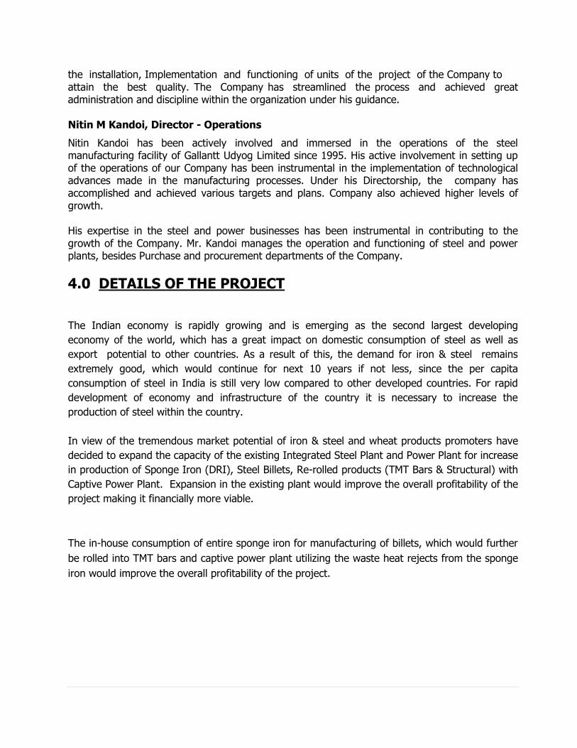
4.0 DETAILS OF THE PROJECT
The Indian economy is rapidly growing and is emerging as the second largest developing
economy of the world, which has a great impact on domestic consumption of steel as well as
export potential to other countries. As a result of this, the demand for iron & steel remains
extremely good, which would continue for next 10 years if not less, since the per capita
consumption of steel in India is still very low compared to other developed countries. For rapid
development of economy and infrastructure of the country it is necessary to increase the
production of steel within the country.
In view of the tremendous market potential of iron & steel and wheat products promoters have
decided to expand the capacity of the existing Integrated Steel Plant and Power Plant for increase
in production of Sponge Iron (DRI), Steel Billets, Re-rolled products (TMT Bars & Structural) with
Captive Power Plant. Expansion in the existing plant would improve the overall profitability of the
project making it financially more viable.
The in-house consumption of entire sponge iron for manufacturing of billets, which would further
be rolled into TMT bars and captive power plant utilizing the waste heat rejects from the sponge
iron would improve the overall profitability of the project.
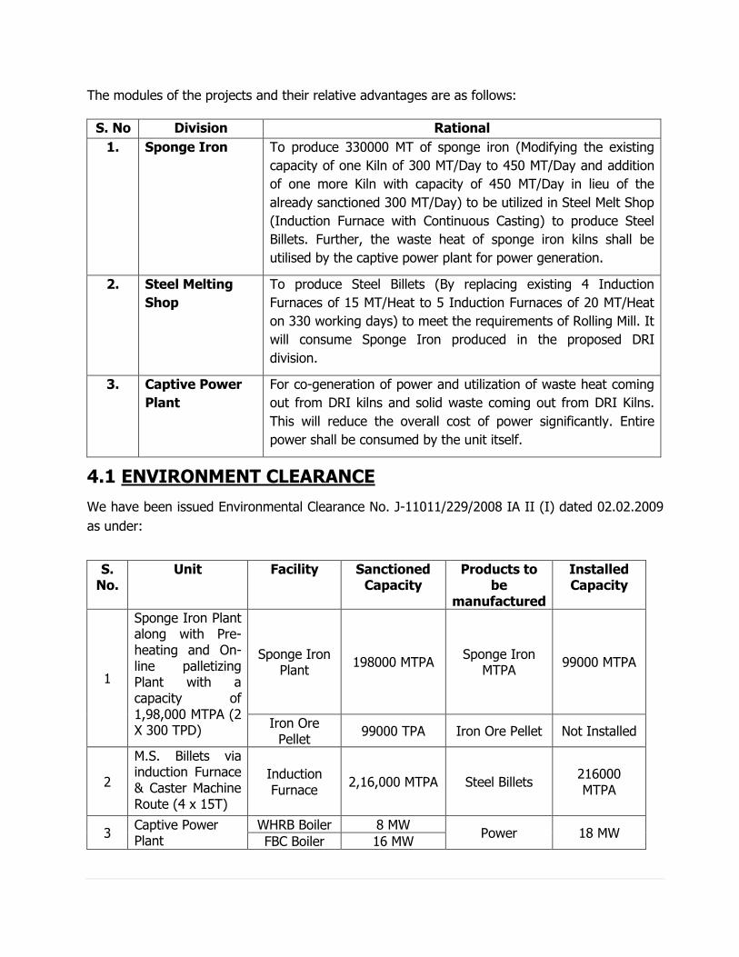
The modules of the projects and their relative advantages are as follows:
S. No Division Rational
1. Sponge Iron To produce 330000 MT of sponge iron (Modifying the existing
capacity of one Kiln of 300 MT/Day to 450 MT/Day and addition
of one more Kiln with capacity of 450 MT/Day in lieu of the
already sanctioned 300 MT/Day) to be utilized in Steel Melt Shop
(Induction Furnace with Continuous Casting) to produce Steel
Billets. Further, the waste heat of sponge iron kilns shall be
utilised by the captive power plant for power generation.
2. Steel Melting
Shop
To produce Steel Billets (By replacing existing 4 Induction
Furnaces of 15 MT/Heat to 5 Induction Furnaces of 20 MT/Heat
on 330 working days) to meet the requirements of Rolling Mill. It
will consume Sponge Iron produced in the proposed DRI
division.
3. Captive Power
Plant
For co-generation of power and utilization of waste heat coming
out from DRI kilns and solid waste coming out from DRI Kilns.
This will reduce the overall cost of power significantly. Entire
power shall be consumed by the unit itself.
4.1 ENVIRONMENT CLEARANCE
We have been issued Environmental Clearance No. J-11011/229/2008 IA II (I) dated 02.02.2009
as under:
S. No.
Unit Facility Sanctioned Capacity
Products to be
manufactured
Installed Capacity
1
Sponge Iron Plant along with Pre-heating and On-line palletizing Plant with a capacity of 1,98,000 MTPA (2 X 300 TPD)
Sponge Iron Plant
198000 MTPA Sponge Iron
MTPA 99000 MTPA
Iron Ore Pellet
99000 TPA Iron Ore Pellet Not Installed
2
M.S. Billets via induction Furnace & Caster Machine Route (4 x 15T)
Induction Furnace
2,16,000 MTPA Steel Billets 216000 MTPA
3 Captive Power Plant
WHRB Boiler 8 MW Power 18 MW
FBC Boiler 16 MW
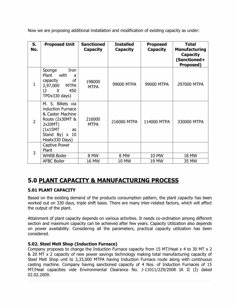
Now we are proposing additional installation and modification of existing capacity as under:
S. No.
Proposed Unit Sanctioned Capacity
Installed Capacity
Proposed Capacity
Total Manufacturing
Capacity (Sanctioned+
Proposed)
1
Sponge Iron Plant with a capacity of 2,97,000 MTPA (2 X 450 TPDx330 days)
198000 MTPA
99000 MTPA 99000 MTPA 297000 MTPA
2
M. S. Billets via induction Furnace & Caster Machine Route (2x30MT & 2x20MT) (1x15MT as Stand By) x 10 Heatx330 Days)
216000 MTPA
216000 MTPA 114000 MTPA 330000 MTPA
3
Captive Power Plant
WHRB Boiler 8 MW 8 MW 10 MW 18 MW
AFBC Boiler 16 MW 10 MW 19 MW 35 MW
5.0 PLANT CAPACITY & MANUFACTURING PROCESS
5.01 PLANT CAPACITY
Based on the existing demand of the products consumption pattern, the plant capacity has been worked out on 330 days, triple shift basis. There are many inter-related factors, which will affect the output of the plant. Attainment of plant capacity depends on various activities. It needs co-ordination among different section and maximum capacity can be achieved after few years. Capacity Utilization also depends on power availability. Considering all the parameters, practical capacity utilization has been considered. 5.02. Steel Melt Shop (Induction Furnace) Company proposes to change the Induction Furnace capacity from 15 MT/Heat x 4 to 30 MT x 2 & 20 MT x 2 capacity of new power savings technology making total manufacturing capacity of Steel Melt Shop unit to 3,33,000 MTPA having Induction Furnace route along with continuous casting machine. Company having sanctioned capacity of 4 Nos. of Induction Furnaces of 15 MT/Heat capacities vide Environmental Clearance No. J-11011/229/2008 IA II (I) dated 02.02.2009.
Selection of Equipment
A. Medium Frequency Induction Furnace:
Medium Frequency Induction Furnace Plant will have 4 Nos. Induction Furnaces and these will utilize:-
i) M. S. Scrap / C. I. Scrap / Pig Iron - 20.10% ii) Continuous Feeding of DRI - 79.99% iii) Melting and Tapping from Induction Furnace - 144 Min. The induction melting technology has brought a significant revolution where it has been proved that the steel produced out of sponge iron mixed with Cast Iron and M.S. Melting Scrap/Pig iron coupled with electric induction furnace, medium frequency, constant power track has become formidable process and can offer better economics at a relatively smaller scale operations. The process involves the charge mix of Raw material mainly Sponge Iron, C. I. Scrap / M. S. Scrap, into molten bath with constant power track through Solid State generator converting A.C. Power into D.C. Power and again to convert the same into A.C. Power after changing the frequency of cycle in between 250 to 500 HZ through thyresters (an electronic device). This converted A.C. power with a frequency of 250 to 500 HZ is passed through capacitor Rack after achieving the de-sired voltage and the same is passed through copper Bus Bar into Molten bath having copper coil, cooled through water circulation, transparent the heat energy into molten bath at constant voltage to melt the Iron and Steel at a temperature of 1625°C. The continuous effort made by technologists has led to the development of the process parameters by which considerable quantity of sponge iron are used in steel making. This has brought a new era in steel melting technology in the country where scrap scarcity can no more be a threat to the mini steel plants. B. Continuous Casting Machine: Liquid Metal from Induction Furnace is carried in a ladle over the Concast Machine. The liquid metal flows from the ladle through a slide gate system underneath it into water cooled copper mould tubes which solidifies the liquid metal into a square shaped mould which we call as M.S. Billets.
From the considered casting cycle time, the number of strands required to cast 100 mm sq. and 110 mm sq. billets is worked out to be two (2). Based on the above, 2 - strand billet casting machine suitable for casting up to 200 mm sq was selected. The caster is 6/11 meter radius machine with two strands with a provision to add one more strand in future.
5.03 DRI Plant: Sponge Iron We have been sanctioned two nos. of DRI Kilns of 300 MT/Day capacities vide Environmental Clearance No. J-11011/229/2008 IA II (I) dated 02.02.2009 and have installed one Kiln of the said capacity. The Company proposes to replace existing sanction DRI Kiln of 300 MT/ Day to 450 MT/Day with second Klin of 450 MT/Day.
The process for the production of sponge iron consists of the reduction of iron ore / pellets with solid carbonaceous material (coal/coke/lignite) in a rotary kiln at high temperature, cooling to room temperature in the rotary cooler with indirect water cooling system, screening and magnetic separation of the product. Sponge iron being magnetic gets attracted and separated from the non-magnetic char.
In the process for the production of sponge iron, the raw materials (iron ore / pellets, feed coal and lime stone /dolomite) are fed to the rotary kiln through feed tube in a pre-determined ratio by electronic weighing equipment. Rotary kiln is generally of 4.2 meters in diameter and 76 Mts. Long and inclined a 2o. It is internally lined with refractory of 250 mm thick. It is rotated by an AC variable speed motor at a steeples variable speed ranging from 0.2 to 1.0 rpm. Due to inclination and rotary motion of the kiln the material moves from the feed end of the kiln to the discharge end in approximately 12 hrs. (Tendency time). The fine coal is blown counter currently from the discharge end of the kiln to maintain the required temperature and the carbon concentration in the bed. The kiln has seven shells air fans mounted on the top which blow air in the respective zones to maintain the required temperature profile. The material and the hot gasses move in the counter current direction and as a result Iron Ore / pellets gets pre-heated and gradually reduced by the time it reaches the discharge end.
The kiln is divided into two zones namely pre-heating zone and reduction zone. The pre-heating zone is normally 30% of the total length of the kiln and the rest is taken as the reduction zone. The material gets heated to the reduction temperature in the pre-heating zone up to 500°C, the iron ore / pellets, coal and limestone gets dried and all the moisture is vaporised. Thereafter, the material moves to reduction zone. In reduction zone, the iron ore/ pellet is deoxidized where the magnetite is reduced to metallic iron. Temperatures are maintained at around 1000 degrees C in this zone to enable the de-oxidization of the Iron ore/ Pellet.
Coal contains sulphur in it. During the decomposition of the coal the sulphur is released in the form of Iron sulphide. The iron sulphide (FeS) has deleterious effect in the steel making and is to be removed. So limestone is used to prevent the sulphur pick up by the sponge iron. All the above reactions are possible only in the presence of CO. The generation of the CO is most important reaction, which is called the Boudard reaction. This reaction is highly endothermic which is also reversible. The conditions favourable for the forward reaction i.e. the generation of CO is: The higher temperature favours the production of CO. The concentration of the reactants has to high so that the forward reaction occurs. Low pressure favours the CO generation.
Oxygen required for the burning of these combustibles is supplied from the air tubes placed along the length of the kiln. By controlled combustion, the temperature in the various zones is maintained so that the reduction is proper and to sufficient degree. The reduction of iron ore/pellet is topo-chemical i.e. the reduction proceeds from the surface to the core. The iron ore/pellet on partial reduction has all the different stages of the reduction.
The hot material after the reduction is complete is then transferred to the rotary cooler via the transfer chute. The rotary cooler is of 3.2 meters dia and 46 mtrs. long made up of Mild Steel shell. It is also inclined at 2° approximately and rotates at variable speed from 0.2- 1.2 rpm. It is driven by an AC variable speed motor. The water is sprayed on the top of the shell, which cools
the material inside the cooler indirectly. The heat from the material is extracted by the shell. In order to increase the surface area for the heat extraction fins are welded inside. Complete shell is covered by thin layer of water. The heat is transferred from the shell to the water by convection. By this the material gets cooled to 80oC and is discharged on the belt conveyor by the double pendulum valve. The double pendulum valve acts as the seal for the prevention of the atmospheric air into the kiln cooler system. The total kiln cooler system is kept under positive pressure. This prevents the atmospheric air from getting into the system. The kiln has to be always operated on positive pressure, as any leakage into the system will cause the re-oxidation of the sponge iron there by causing the drop in the quality of the product. The material after the discharge from the cooler is dropped on to the cooler discharge conveyor. A diversion chute is provided at the head end of this conveyor for diversion of the material in case of break down in the production separation. The material is then sent to the product separation system. In product separation system consisting of double deck screen, the material is screened to 0-15 mm size fractions. The oversize i.e. +20 mm obtained is small quantity so it is taken on the floor or diverted to the sponge iron bin. The 0-3mm size fraction is called the fines are fed to a drum type magnetic separator where the magnetic sponge iron fines and the non-magnetic dolochar separated and fed to the respective bins through the chutes and conveyor. The coarser fraction is similarly separated by another magnetic separator and fed to respective bins. This magnetic fraction is called the sponge iron lumps and the non- magnetic as dolochar which is the unburned coal. This dolochar acts as a fuel for our captive power plant. As such, it is transferred to power plant through conveyors and is consumed along with coal in there boiler to generate power.
The gasses, which flow in the counter current direction of the material, go to the dust-settling chamber where the heavier particles settle down. These particles are continuously removed by the wet scrapper system. The gasses then pass to the after burner chamber where the residual carbon or CO is burned by the excess air available. The gasses are at high temperature and have lot of heat energy, which shall be utilized for the power generation through the waste heat recovery boiler. The hot gasses after the heat recovery boiler get cooled to below 200°C. The gases are then cleaned passing the gasses to ESP (Electrostatic precipitator). This clean gas at a temperature of below 90 degree centigrade is passed into the atmosphere through the chimney. 5.04 Captive Power Plant
Company has been sanctioned 16 MW AFBC and 8 MW WHRB vide Environmental Clearance No. J-11011/229/2008 IA II (I) dated 02.02.2009. Against this sanction, Company has installed 10 MW AFBC and 8 MW WHRB (18 MW), hence there is a balance sanctioned capacity of 6 MW of AFBC. We hereby propose to install additional capacity of 29 MW (19 MW CFBC and 10 MW WHRB) with the existing sanctioned thereby making the total 53 MW; (i.e. 18 MW Installed) + (6 MW AFBC balance of sanction) + proposed to install (10 MW WHRB & 19 MW CFBC). Presently company has an AFBC of 40 TPH capacity which can generate 10 MW power using bio mass as fuel, besides a WHRB of 35 TPH capacity is also installed which generates 8 MW power using waste heat of DRI kiln as fuel thus unit have a total installed capacity of 18 MW. Company further proposes installation of 1 number 110 TPH CFBC boiler which generate 27 MW and 35
TPH WHRB Boiler which generate 8 MW making a total additional capacity of 35 MW. After this addition the total power generation capacity of the unit will be 53 MW. The proposed CPP consist of two waste heat recovery boiler of 35 TPH steam generation capacity and one Fluidized Combustion Boiler (FBC) of 110 TPH besides existing AFBC of 40 TPH steam generation capacity. Company shall be installing turbine of one number of 25 MW and one number of 10 MW in addition to the existing turbine of 18 MW. Company proposes to sale surplus power between 4 MW to 9 MW generated through bio-mass to UPPCL. Waste Heat Recovery Boiler The waste heat recovery boiler of both the Kilns will generate 70 TPH of steam with the outlet parameters of 110 Ksc(a) and 640 Deg. C., while taking in the feed water at 160° C from the de-aerator. The entire waste gas from the sponge iron kiln will be utilized in the waste heat boiler for the steam generation. 70 TPH of steam generated in the boiler is fed to the main steam line. About 0.25 TPH of steam is used for the ejector and turbine gland sealing after pressure and temperature reduction to 235 Deg.C. Around 0.096 TPH of feed water is used as spray. 68.36 TPH of steam is fed to the extraction cum condensing turbine. The uncontrolled extraction from the turbine at 6.5 Ksc (a) gives 6.26 TPH of steam approximately at a temperature of 231 Deg.C. This steam is used in the de-aerator, for heating up the feed water to temperature of 160 Deg.C. Atmospheric Fluidised Bed Combustion Boiler Fluidised bed combustion is a "Clean Technology for a better tomorrow" where technology and economy have been interwoven harmoniously in quest of a better environment. The environmentally friendly perspective of this technology is as follows:
At the low combustion temperature of 850°C / 900°C, no Nitrogen Oxides result from the Nitrogen in the combustion air, with the end result of extremely low NOx emissions even with fuels rich in Nitrogen.
Formation of SOX is essentially prevented by the addition of limestone. This is both mixed into the fuel and blown into the combustion chamber. Due to the favourable conditions in the fluidized bed, about 90% of the resulting Sulphur Oxides can be removed.
Better Plant flexibility at partial loads of about 25% and quick load changes.
Low Auxiliary Power consumption compared to other coal fired Boiler versions.
The Steam Generator would be semi-outdoor type, natural circulation, balanced draft, Single-drum, designed for firing different grades of coal. The Boiler is of bubbling fluidised bed type to handle even high ash coal.
Capacity of AFBC coupled with adjacent WHRB has been selected to ensure adequate margin
over the requirement of turbine at 100% MCR. AFBC would be designed to operate with "The HP heaters out of service" condition (resulting in lower feed water temperature at Economizer inlet) and deliver Steam to meet the Turbo-Generator requirement at 100% MCR. Economizer section of the Boiler would be non-Steaming type. Super heater sections would be convection type and designed so as to maintain rated Steam temperature of 540°C (:i: 5°C) at super heater outlet over the control range of 60% to 100%, MCR. Attemperator is provided at the outlet of convection super heater for temperature control at Steam Generator outlet. The Boiler furnace and flue gas passages would be designed for appropriate low velocities in order to minimize erosion. Suitable balanced draft System would be provided for the Steam Generator with one forced draft and one induced draft fans. Each of these fans would be capable of meeting the air requirement at 100% Boiler MCR load. The forced draft fans would be radial type with inlet vane control for regulation of airflow. The induced draft fans would be radial type with multi louver damper control the regulation. The forced draft fans would control total air flow to Boiler and the induced draft fan would control furnace draft of the Boiler through automatic control loops. In addition to the FD fan, one primary air fan of 100% capacity shall be provided for transportation of fuel.
The Boiler would be top supported type and would be provided with all supporting Steel platforms, galleries and stairways for easy approach and Maintenance of the Unit. Adequate weather protection would be provided for instruments and operating personnel. Necessary insulation along with skin casing to limit outside surface temperature to the safe level would be provided.
Steam Turbine Generators and Auxiliaries STEAM TURBINE The Steam Turbine will be of condensing type. The set will be complete with Condenser, Air Evacuation System, 2 x 100% Condensate Extraction Pumps, Generator Cooling, System, Gland Sealing with Gland Vent Condenser, Lube Oil System, LP & HP Re-generative Feed Heaters, etc.
EXCITATION SYSTEM
The Excitation System envisaged will be brush-less type. The Excitation System shall be capable of Supplying the Excitation Current of the Generator under all condition of Operation of Load, Voltage and Power. Rated current and Voltage of the Exciter shall be at least 120% of normal Excitation Current and at least 110% of no Load Excitation
Voltage with maximum of 140% ceiling. The Exciter response ratio shall be greater than 1.5. The Field Breaker and Field Suppression System will also be part of Exciter System. Automatic high speed Thyristorised, Auto Manual AVR capable of maintaining Steady State Terminal Voltage within :I: 0.5% of the preset Value under all Operating Conditions and capable of smooth and continuous running over the Operating Range. The Generators shall be provided with Temperature Detector embedded at different location, i.e. Stampings, Stator Windings, etc.
6.0 RAW MATERIAL AVAIBILITY & SPECIFICATION 6.01 Steel Melt Shop Division (Induction Furnace with Continues Caster) The raw materials are easily available and will be sourced as under:
1. Sponge iron will be procured from company's own sponge iron division. 2. M.S. Scraps and other variety of scraps will be procured from local suppliers. 3. The Ferro Alloys will be procured from manufacturers across India.
6.02 Sponge Iron Division
The major Raw Materials required for production of Sponge Iron by the rotary kiln process are: sized graded iron ore or pellets and Non-Coking coal. Dolomite, in small quantities which are easily available in the open market.
6.03 Captive power Plant
Out of the total sanctioned and proposed capacity of 53 MW, 18 MW shall be produced by waste heat of sponge iron division for which no fuel is required. For 35 MW Circulating Fluidized Combustion Boiler (CFBC) / Atmospheric Fluidised Bed Combustion (AFBC) Boiler, coal, rice husk and dolochar shall be used. Dolochar is the burnt coal generated during the sponge iron production as a bye product. It acts as a fuel for this boiler. Entire dolochar generated shall be consumed by power plant. Thus, very small quantity of coal and rice husk shall be required for the operations. The same shall be managed from open market.
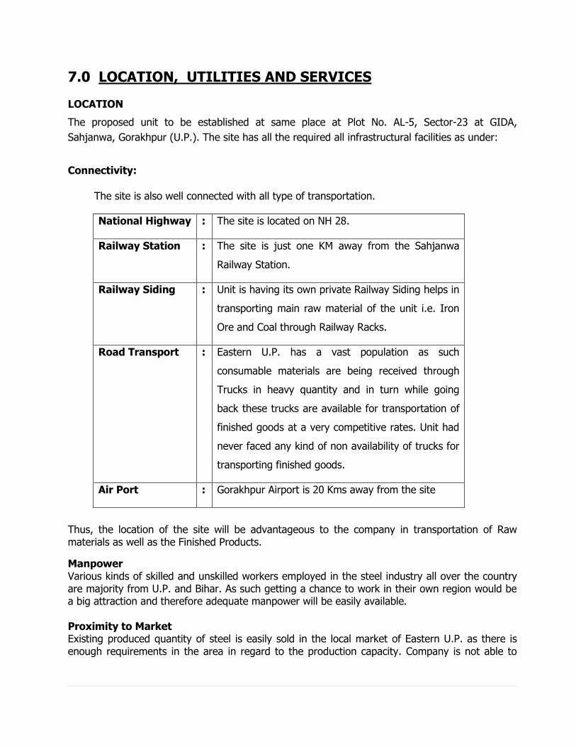
7.0 LOCATION, UTILITIES AND SERVICES LOCATION
The proposed unit to be established at same place at Plot No. AL-5, Sector-23 at GIDA,
Sahjanwa, Gorakhpur (U.P.). The site has all the required all infrastructural facilities as under:
Connectivity:
The site is also well connected with all type of transportation.
National Highway : The site is located on NH 28.
Railway Station : The site is just one KM away from the Sahjanwa
Railway Station.
Railway Siding : Unit is having its own private Railway Siding helps in
transporting main raw material of the unit i.e. Iron
Ore and Coal through Railway Racks.
Road Transport : Eastern U.P. has a vast population as such
consumable materials are being received through
Trucks in heavy quantity and in turn while going
back these trucks are available for transportation of
finished goods at a very competitive rates. Unit had
never faced any kind of non availability of trucks for
transporting finished goods.
Air Port : Gorakhpur Airport is 20 Kms away from the site
Thus, the location of the site will be advantageous to the company in transportation of Raw materials as well as the Finished Products.
Manpower Various kinds of skilled and unskilled workers employed in the steel industry all over the country are majority from U.P. and Bihar. As such getting a chance to work in their own region would be a big attraction and therefore adequate manpower will be easily available. Proximity to Market Existing produced quantity of steel is easily sold in the local market of Eastern U.P. as there is enough requirements in the area in regard to the production capacity. Company is not able to
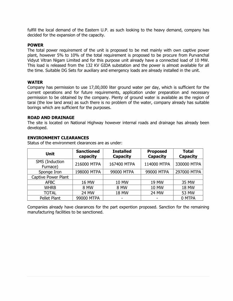
fulfill the local demand of the Eastern U.P. as such looking to the heavy demand, company has decided for the expansion of the capacity. POWER The total power requirement of the unit is proposed to be met mainly with own captive power plant, however 5% to 10% of the total requirement is proposed to be procure from Purvanchal Vidyut Vitran Nigam Limited and for this purpose unit already have a connected load of 10 MW. This load is released from the 132 KV GIDA substation and the power is almost available for all the time. Suitable DG Sets for auxiliary and emergency loads are already installed in the unit.
WATER Company has permission to use 17,00,000 liter ground water per day, which is sufficient for the current operations and for future requirements, application under preparation and necessary permission to be obtained by the company. Plenty of ground water is available as the region of tarai (the low land area) as such there is no problem of the water, company already has suitable borings which are sufficient for the purposes. ROAD AND DRAINAGE The site is located on National Highway however internal roads and drainage has already been developed. ENVIRONMENT CLEARANCES Status of the environment clearances are as under:
Unit Sanctioned
capacity Installed Capacity
Proposed Capacity
Total Capacity
SMS (Induction Furnace)
216000 MTPA 167400 MTPA 114000 MTPA 330000 MTPA
Sponge Iron 198000 MTPA 99000 MTPA 99000 MTPA 297000 MTPA
Captive Power Plant
AFBC 16 MW 10 MW 19 MW 35 MW
WHRB 8 MW 8 MW 10 MW 18 MW
TOTAL 24 MW 18 MW 24 MW 53 MW
Pellet Plant 99000 MTPA - - 0 MTPA
Companies already have clearances for the part expention proposed. Sanction for the remaining manufacturing facilities to be sanctioned.
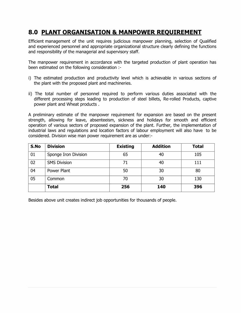
8.0 PLANT ORGANISATION & MANPOWER REQUIREMENT
Efficient management of the unit requires judicious manpower planning, selection of Qualified and experienced personnel and appropriate organizational structure clearly defining the functions and responsibility of the managerial and supervisory staff. The manpower requirement in accordance with the targeted production of plant operation has been estimated on the following consideration :- i) The estimated production and productivity level which is achievable in various sections of
the plant with the proposed plant and machineries. ii) The total number of personnel required to perform various duties associated with the
different processing steps leading to production of steel billets, Re-rolled Products, captive power plant and Wheat products .
A preliminary estimate of the manpower requirement for expansion are based on the present strength, allowing for leave, absenteeism, sickness and holidays for smooth and efficient operation of various sectors of proposed expansion of the plant. Further, the implementation of industrial laws and regulations and location factors of labour employment will also have to be considered. Division wise man power requirement are as under:-
S.No Division Existing Addition Total
01 Sponge Iron Division 65 40 105
02 SMS Division 71 40 111
04 Power Plant 50 30 80
05 Common 70 30 130
Total 256 140 396
Besides above unit creates indirect job opportunities for thousands of people.
9.0 IMPLEMENTATION SCHEDULE
The installation of several production units along with utilities and services require co-
operation for procurement of equipment, equipment foundations, award of all contracts and
supervision of all construction jobs at plant site. The project implementation schedule has
been drawn up to maintain a strict time schedule. The factors which are responsible for timely
implementation of the project are :-
i) Arrangement of proper finance for the project.
ii) Finalization of layout of the proposed plant.
iii) Design of utilities and services.
iv) Placement of orders for plant and machinery.
v) Arrangements for Govt. sanctions and supply of power.
i) Recruitment of personnel.
Construction materials
It is envisaged that cement, reinforcing steel and structural steel materials, sheets will be procured by the company and issued to the contractors free of cost or at agreed recovery rates. For this, advance action has to be initiated by the company so that these materials are sufficiently stored in adequate quantity before commencement of the work at site. All other construction materials will be procured by the contractors.
Construction facilities
Construction facilities will mainly include providing infrastructural arrangement like water, power, road, drainage storages etc. Company proposes that entire construction shall be done by a competent civil contractor
The implementation schedule of the project are as under: