Page 1
Pre Feasibility Report of Kedla UG (0.18MTY), CCL
Job No: 311248 1 of 77 RI-III, CMPDI
PRE-FEASIBILTY REPORT OF KEDLA UGP (0.18 MTY)
CONTENTS
CHAPTER PARTICULARS PAGE NO.
List of Contents
Summarized Data 4 - 9
I Introduction 10 - 11
II Marketability & Justification 12 - 13
III Project Site Information 14
IV Geology & Deposit Appraisal 15 - 19
V Mine Boundary, Reserves & Mine Life 20 - 22
VI Mine Entries 23 - 24
VII Mining Strategy 25 - 28
VIII Method of Mining 29 - 36
IX Mining Schedule 37
X Horizontal and Vertical Transport 38 - 39
XI Mine Ventilation 40 - 41
XII Water Management, Pumping & Drainage 42 - 43
XIII Coal Handling Plant & Despatch 44 - 46
XIV Workshop Store & Magazine 47
XV Power Supply, Illumination & Communication 48 - 63
XVI Civil Construction 64 - 66
XVII Manpower, Productivity & Training 67 - 68
XVIII Safety & Conservation 69 - 71
XIX Environment Management 72
XX Mine Closure Planning 73
XXI Project Implementation Schedule 74 - 75
XXII Financial Evaluation 76 - 77
Appendices
Page 2
Pre Feasibility Report of Kedla UG (0.18MTY), CCL
Job No: 311248 2 of 77 RI-III, CMPDI
PRE-FEASIBILTY REPORT OF KEDLA UGP (0.18MTY)
LIST OF APPENDICES
Appendix No.
Particulars Page No.
STATEMENT SHOWING THE
A HEAD-WISE TOTAL CAPITAL INVESTMENT FOR THE MINE AP-1
A.1 ESTIMATED CAPITAL INVESTMENT ON LAND AP-2
A.2 ESTIMATED TOTAL CAPITAL INVESTMENT ON CIVIL WORKS AP-3
A.2.1 ESTIMATED CAPITAL INVESTMENT ON SERVICE BUILDINGS AP-4
A.2.2 ESTIMATED CAPITAL INVESTMENT ON RESIDENTIAL BUILDINGS AP-5
A.2.3 ESTIMATED COST INDEX FOR CIVIL WORKS AP-6
A.2.4 UNIT COST OF RESIDENTIAL BUILDINGS AP-7
A.3 ESTIMATED TOTAL CAPITAL INVESTMENT ON PLANT & MACHINERY AP-8
A.3.1 ESTIMATED CAPITAL INVESTMENT ON ELECTRICAL P & M AP-9
A.3.2 ESTIMATED CAPITAL INVESTMENT ON WORKSHOP P & M AP-10
A.3.3 ESTIMATED CAPITAL REQUIREMENT FOR PUMPS, PIPES & FITTINGS AP-11
A.4 ESTIMATED CAPITAL INVESTMENT ON FURNITURE & FITTINGS AP-12
A.5 ESTIMATED CAPITAL INVESTMENT ON RAILWAY SIDING AP-13
A.6 ESTIMATED CAPITAL INVESTMENT ON VEHICLES AP-14
A.7 CAPITAL INVESTMENT ON PROSPECTING & BORING AP-15
A.8.1 ESTIMATED CAPITAL OUTLAY IN MINES AP-16
A.8.2 ESTIMATED CAPITAL INVESTMENT ON ROADS & CULVERTS AP-17
A.8.2.1 CAPITAL INVESTMENT ON APPROACH ROAD & CULVERTS AP-18
A.8.2.2 CAPITAL INVESTMENT ON COLONY ROAD & CULVERTS AP-19
A.8.2.3 CAPITAL INVESTMENT ON APPROACH ROAD TO MAGAZINE AP-20
A.8.3.1 CAPITAL INVESTMENT FOR COLONY WATER SUPPLY AP-21
A.8.3.2 CAPITAL INVESTMENT ON SEWERAGE EFFULENT TREATMENT AP-22
A.8.3.3 CAPITAL INVESTMENT FOR INDUSTRIAL WATER SUPPLY AP-23
A.8.3.4 CAPITAL INVESTMENT ON SEWERAGE EFFLUENT TREATMENT AP-24
A.8.4 ESTIMATED CAPITAL INVESTMENT ON EMP AP-25
A.8.4.A CAPITAL INVESTMENT ON ENVIRONMENTAL POLLUTION & CONTROL MEASURES
AP-26
A.8.5 ESTIMATED CAPITAL INVESTMENT ON RESEARCH & DEVELOPMENT AP-27
B ESTIMATED JOB-WISE/CATEGORY-WISE REQUIREMENT OF MANPOWER AP-28
C.1 ESTIMATED COST OF PRODUCTION PER TONNE OF COAL AT 100% AP-29
C.2 ESTIMATED COST OF PRODUCTION PER TONNE OF COAL AT 85% AP-30
D.1 ESTIMATED NET REVENUE CASH OUTFLOW AND IRR AT 100% CAPACITY AP-31
D.2 ESTIMATED NET REVENUE CASH OUTFLOW AND IRR AT 85% CAPACITY AP-32
Page 3
Pre Feasibility Report of Kedla UG (0.18MTY), CCL
Job No: 311248 3 of 77 RI-III, CMPDI
PRE-FEASIBILTY REPORT OF KEDLA UGP (0.18MTY)
LIST OF PLATES
Plate No. Particulars Scale
I Location Plan of Kedla UGP 1 : 5000
II Geological Plan of kedla UGP 1 : 5000
III Layout Plan of Seam-VIII 1 : 5000
IV Layout Plan of Seam-VI 1 : 5000
V Layout Plan of Seam-VA 1 : 5000
VI Land Use Plan of Kedla UGP 1 : 5000
VII Surface Plan of Kedla UGP 1 : 5000
VIII Topographical Plan of Kedla UGP 1 : 5000
PRE-FEASIBILTY REPORT OF KEDLA UGP (0.18MTY)
LIST OF ANNEXURES
S. No. Particulars
1 Table of Extractable reserve for seam-VIII, VI, VA
2 Schematic Diagram of Power Distribution of Kedla UGP at surface &
Underground
3 G.A of truck loading system at kedla UG
Page 4
Pre Feasibility Report of Kedla UG (0.18MTY), CCL
Job No: 311248 4 of 77 RI-III, CMPDI
PRE-FEASIBILTY REPORT OF KEDLA UGP(0.18 MTY)
SUMMARISED DATA
S.N. Particulars Unit Title / Value
A. GENERAL
1. Name of Project Kedla UGP
2. Name of CCL Command Area in which project lies.
Hazaribag Area , CCL
3. Nearest Railway Station from project Name Km
Danea Railway Station 9.0 Km (approx.)
4. Nearest National / State Highway/ Approach Road
Name Km
NH-33
B. GEOLOGICAL
1. Name of geological blocks considered Name Part of Kedla Block
2. Area of the geological blocks Considered for UG mine
Sq.Km. 3.335
3. Borehole within the considered Geological Blocks
BHs/sq.km. 26 (overall)
4 Actual Mining Area Sq.km 3.335
5. Description of all coal seams within block
Seam Thickness Range (m) Borehole
intersections Geological Reserve
1 2 3 4
Surface Cover
XIA 0.52 1
Parting 1.01
XI 5.45-7.52 3
Parting 7.71-8.48
XA 0.25-1.95 5
Parting 13.14-21.07
X 4.00 -7.70 5
Parting 23.63-34.85
IXA 0.24-1.00 8
Parting 8.82-15.28
IX 0.50-2.10 16 0.806
Parting 10.97-35.77
VIII C 0.20-1.55 26
Parting 4.14-24.49
VIII B 0.10-1.94 37 3.021
Parting 0.70-18.39
VIIIA 0.26-1.85 39
Parting 1.70-18.80
VIII 1.30-4.50 49 8.075
Parting 1.81-17.74
VIIC 0.09-1.46 40
Parting 0.41-10.83
VIIB 0.07-2.44 49
Parting 1.15-31.84
VIIA 0.07-1.90 43
Page 5
Pre Feasibility Report of Kedla UG (0.18MTY), CCL
Job No: 311248 5 of 77 RI-III, CMPDI
S.N. Particulars Unit Title / Value
Parting 5.48-37.21
VII TOP 0.16-3.85 60 3.860
Parting 0.26-2.80
VII BOTTOM 0.46-4.97 61 3.959
VII COMB 3.80-4.90 2
Parting 0.06-4.10
VI 0.21-3.93 60 6.983
VII/VI 3.54-6.30 8
Parting 0.25-3.94
VA 3.00-7.80 73 21.242
VII/VI/VA 8.10-12.65 4
Parting 6.70-47.25
V 4.40-11.60 94 54.281
Parting 3.17-21.29
IV 1.27-7.70 122 38.962
Parting 0.90-17.29
III A 0.10-1.90 76
Parting 1.30-19.30
III Top 1.80-7.00 90 42.135
Parting 0.30-8.81
III Bottom 0.16-3.71 91 5.147
III Comb. 4.35-5.09 3
Parting 1.18-21.60
II B 0.20-2.28 83 10.445
Parting 1.06-14.25
II A 0.06-3.90 73 10.937
Parting 3.05-21.50
II Top 0.55-3.00 77 16.177
Parting 1.10-10.51
II Bottom 0.52-6.00 82 24.664
II Comb 3.65-6.50 14 14.140
Parting 12.20-41.40
I 0.61-10.50 83 48.434
Parting 77.13-112.62
0 0.35-5.35 57 15.936
C. TECHNICAL
1. Area of the proposed mine
Sq.km. 3.335 sq.km
2. Borehole intersection up to Target Seam( I,e Seam-VA ) within the considered geological Blocks
73
3. Mine parameters Max Extent along strike Max Extent along dip
Km Km
Mine No-1 Along strike : 1.5 km(max) Along Dip : 1.00 km( max) Mine No-3 Along strike : 1.8 km( max) Along Dip : 1.0 km( max)
4. Coal seams proposed to be worked Development of Seam-VIII , VI & VA
5. Mine Entries
Page 6
Pre Feasibility Report of Kedla UG (0.18MTY), CCL
Job No: 311248 6 of 77 RI-III, CMPDI
Entries Name/ No. Size (X-section / length) (mxm/m)
Gradient (1 in …../vertical)
Approach (from / to)
(surface/seam to seam)
Purpose
Mine No-1
Incline No.1A 4.2 x 2.8 1 in 10 Surface to Seam-VIII
Intake(Haulage)
Incline No.1B 4.2 x 2.8 1 in 10 Surface to Seam-VIII
Intake (Traveling)
Airshaft Dia -4.2m 10m Surface to Seam-VIII
Return
Mine No-3
Incline No.3A 4.2 x 2.8 1 in 8 Quarry Edge to Seam-VA
Intake(Haulage)
Incline No.3B 4.2 x 2.8 1 in 8 Quarry Edge to Seam-VA
Intake (Traveling)
Airshaft Dia -4.2m 20m Quarry Edge to Seam-VA
Return
SN
Particulars Unit Value
6. Method of Mining B&P (SDL)
7. Panel Parameters No. of headings in each panel
Size of galleries / roadways Pillar sizes
Nos.
m m x m
5 to 7
4.2 m x 3.0 m or seam thickness
28m x 28 m
8. Production Parameters No. of panels to be worked
Production from 2 panels
Nos.
TPD
2.0
600
9. Target Output Nominal production capacity (at 100%) Peak production capacity (at 120%) Production capacity (at 85%)
Mt Mt
Mt
0.18 0.22
0.15
10. Year of achieving target production (from zero date)
4 th Year
11. Production phasing (from zero date upto target year)
Year / Project
Year 1 Year 2 Year 3 Year 4 Year 5 to 18
Kedla UGP 0.09 0.09 0.14 0.18 0.18
12 Total mine life (at Nominal production
Years
18 years
Page 7
Pre Feasibility Report of Kedla UG (0.18MTY), CCL
Job No: 311248 7 of 77 RI-III, CMPDI
capacity)
Construction period
Production build-up period
Targeted Production
Tapering / mine closure period
Years
Years
Years
Years
2 years
1 years
4 th years
1 year
13. Degree of gassiness (I/ II/ III) Degree- I (assumed)
14. Major equipment deployed in panels
Nos. SDL : 2 Set ( 6 nos) UDM : 2 set(4nos)
15. Average specific energy consumption
kWh/t
16. Total net manpower(proposed) Existing
Additional
Nos. Nos. Nos.
502 Nil Nil
17. Overall output per manshift (OMS)
Existing Incremental
Tonnes Tonnes Tonnes
1.36 (w.r.t net manpower) 0.44
SN
Particulars Unit Value
18. Grade of coal W-III to W-IV
19. Presence of Major Surface constraints (forest, nallas, road, power line, etc.)
(type) Forest Land within the mining area
20. Coal Transport i. Incline ii. Main trunk
roadway iii. Panel
i. By belt conveyor ii. -do- iii. –do-
21. Men Transport Man-riding system
22. Surface coal transport (from Pithead to washery)
Point of sale is washery
23. Name of any specific customer / industry
As decided by the Company
D. ENVIRONMENTAL & OTHERS
1. Civil Construction Residential houses
Housing satisfaction
Nos.
%
Nil 55
2. Potable Water Demand Industrial Water Demand
238 KLPD 0.024MLPD
Page 8
Pre Feasibility Report of Kedla UG (0.18MTY), CCL
Job No: 311248 8 of 77 RI-III, CMPDI
3. Total land in Possession Non Forest Land
Forest land
Ha Ha.
274.72 58.78
4. Land to be acquired Non Forest Land
Forest land
Ha. Ha. Ha.
333.50 274.72 58.78
5. N.P.V for Non-Forest land N.P.V for Forest Land
Total Area Total Value
Rs. Lakhs / ha.
Rs Lakh/Ha Ha.
Rs.Lakhs
25.00
9.0 58.78
349.94
6. Cost of land & Rehabilitation Total Cost of Land
R&R Cost
Rs.Crores
3.94 Nil
7. Total EMP capital Environmental Protection Cost
Rs.Lakhs Rs / Te
60.00 6.00
8. Average annual rainfall mm 1200-1400
9. Make of Water Lit / sec 208
SN
Particulars Unit Value
11 Total installed pumping capacity (through borehole or through incline/ shaft)
LPS 240
12 Drainage of the Area (Name of river / nallah)
Chutua Nala
13 Any proposed diversion of nala or power line
Nil
E. FINANCIAL
1. Total Capital Investment Upto Target
Existing Additional
Beyond Target
Rs. Crores
53.91 14.67 39.24 5.13
2. Specific Investment upto Target
Rs./tonne 2994.76
3. Total Capital Investment on P&M
Upto Target Beyond Target
Rs.Crores
35.46 2.45
4. Specific Investment on P&M upto Target
Rs./tonne 1969.98
5. Additional Capital requirement Rs.Crores 39.24
Page 9
Pre Feasibility Report of Kedla UG (0.18MTY), CCL
Job No: 311248 9 of 77 RI-III, CMPDI
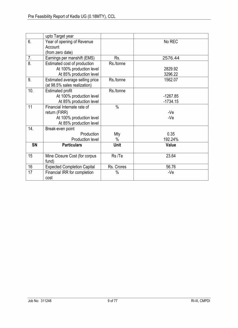
upto Target year
6. Year of opening of Revenue Account (from zero date)
No REC
7. Earnings per manshift (EMS) Rs. 2576.44
8. Estimated cost of production At 100% production level At 85% production level
Rs./tonne 2829.92 3296.22
9. Estimated average selling price (at 98.5% sales realization)
Rs./tonne 1562.07
10. Estimated profit At 100% production level At 85% production level
Rs./tonne -1267.85 -1734.15
11 Financial Internate rate of return (FIRR)
At 100% production level At 85% production level
% -Ve -Ve
14. Break-even point Production
Production level
Mty %
0.35
192.24%
SN
Particulars Unit Value
15 Mine Closure Cost (for corpus fund)
Rs /Te 23.64
16 Expected Completion Capital Rs. Crores 56.76
17 Financial IRR for completion cost
% -Ve
Page 10
Pre Feasibility Report of Kedla UG (0.18MTY), CCL
Job No: 311248 10 of 77 RI-III, CMPDI
CHAPTER-I
INTRODUCTION
1.0 BACKGROUND OF THE REPORT
As per the Project Monitoring Report of CCL & letter of CGM(P&P) vide letter no
CGM(P&P)/2012/2759-60 dated 24.8.2012 , Kedla UG is an existing mine. Presently, the property
under Kedla UG is being worked through three set of separate inclines / mines. Seam VIII has
been approached from Mine Nos. 1 & 2 while seam V-A has been approached from Mine No. 3
and reverse drift from seam-VIII.
As per the CCL authority, it was communicated vide note sheet no CCL (H) / P&P / (2/8) /622
dated 27.9.2012 that, the said mine is running under violation and it requires fresh EMP. For the
said purposes, a pre feasibility report for kedla UGP is required.
1.1 SCOPE OF WORK
The scope of this pre feasibility report is limited to
a) Development & Depillaring of Seam-VIII. This seam is the top seam in the mining area of
Kedla UG and around 90% of the area is developed and depillared. Only 10% area is left,
which is partly developed & standing on pillar and partly virgin.
b) Development of underlying Seam-VA with the existing mine entries.
c) Development of underlying seam-VI which is around 3.0m above seam-VA.
1.2 REASONS FOR THIS LIMITED SCOPE
This report is only for EMP approval of kedla underground for a limited period to avoid
violation (up to the period of proposed kedla opencast (6.0Mty) comes in operation).
The mining area of existing Kedla underground has already been considered in the proposed
Kedla opencast project (6.0 MTY) up to seam-I and shelved due overburden dump problem.
Kedla opencast may be started only after exhaustion of Gose opencast. It is being proposed
that after liquidation of Gose Opencast in its adjoining area, the overburden of Kedla OCP will
be dumped into the de-coaled area of Gose opencast.
Seam-VIII, VI & V’A’ has already considered in the proposed project report of Kedla opencast.
This feasibility report also proposes the working in same seam.
Page 11
Pre Feasibility Report of Kedla UG (0.18MTY), CCL
Job No: 311248 11 of 77 RI-III, CMPDI
The extraction of developed seam-VI, V’A’ by opencast will give higher percentage of recovery
in comparison to depillaring by underground mining methods.
Seam-VIII is mostly developed & depillared up to its full seam thickness except a small patch.
Hence this report envisages only development of seam-V’A’ and seam- VI & development
&depillaring of left out patch of seam-VIII.
Page 12
Pre Feasibility Report of Kedla UG (0.18MTY), CCL
Job No: 311248 12 of 77 RI-III, CMPDI
CHAPTER-II
MARKETABILITY & JUSTIFICATION
2.1 DEMAND AND SUPPLY SCENARIO
The demand and supply scenario for CCL is given below:
S.N Particulars 2012-13 2013-14 2014-15 2015-16 2016-17
A PSA/LOA Commitment at 100% level without any regulation
1 For Power Sector 59.75 61.00 70.39 73.73 73.73
2 Other than Power Sector 16.35 16.35 16.35 16.35 16.35
3 E-auction @ 10% of total
production
5.50 6.20 7.00 7.60 8.30
4 Total Demand 81.60 83.55 93.75 97.68 98.38
5 Total Production 55.00 62.00 70.00 76.00 83.00
Gap -26.60 -21.55 -23.75 -21.68 -15.38
2.2 UTILITY OR MARKET FOR THE COAL FROM PROJECT
The coal produced from the proposed kedla Underground project will be of medium coking coal. Its
grade will vary from W-III to W-IV. Our country has huge requirement of coking coal for steel
industry. Presently our countries coking coal requirement is filled with indigenous coking coal
production of my country. Hence it is partly met by the import of coking coal from abroad. The coal
produced from this project will get good market potentiality and it will help in reducing the import of
coking coal from abroad.
2.3 AVAILABLE LINKAGE
The coal from the proposed Underground project is proposed for basket linkage from the mine pit
top to kedla washery. The point of sell of the coal produced from the proposed kedla underground
will be kedla washery.
2.4 JUSTIFICATION OF OPENING THE PROJECT BASED ON MARKETABILITY
Coal produced from Kedla underground is of medium grade coking coal ( grade varies from W-
III to W-IV )
Page 13
Pre Feasibility Report of Kedla UG (0.18MTY), CCL
Job No: 311248 13 of 77 RI-III, CMPDI
The demand of superior grade coal is very high in the country; hence, it can be easily marketed.
The company is facing a negative gap between demand and availability of coal as shown in the
table above.
Page 14
Pre Feasibility Report of Kedla UG (0.18MTY), CCL
Job No: 311248 14 of 77 RI-III, CMPDI
CHAPTER-III
PROJECT SITE INFORMATION
3.0 LOCATION & ACCESSABILITY
The integrated Kedla Block, lies in the West Bokaro Coalfields of CCL & is covered by survey of
India Topo Sheet No E 73/ 9 on RF 1 : 50,000. The area is also covered by the aerial photographs
on RF 1 : 10,000.
The NH-33, connecting Ranchi & Hazaribagh town passess along the western fringe of the
coalfields. The block is approachable from Naya more Kuju along the coal trunk route. The
nearest railway station is Danea railway station at an about 9.0km from the eastern fringe of the
block. The nearest airport is located at ranchi at a distance about 100km.
3.1 PHYSIOGRAPHY AND DRAINAGE
The general elevation varies from 326m to 388m.The natural topography of the area has been
obliterated to a certain extent by a network of opencast mine. However, in general, the topography
is undulating and at places is seen to be broken by hillocks. The topography is rugged in the NW
part also. It is rugged & hilly.
The drainage of the block is controlled by the Eastern flowing Chutua Nala in the north along the
northern boundary, the easterly flowing Bokaro River in the south beyond the block boundary.
3.2 CLIMATE
The climate is extreme during summer and temperature reaches up to 46 degree and during winter
comes down up to 5 degree Celsius.
Page 15
Pre Feasibility Report of Kedla UG (0.18MTY), CCL
Job No: 311248 15 of 77 RI-III, CMPDI
CHAPTER-IV
GEOLOGY & DEPOSIT APPRAISAL
4.1 GEOLOGY OF THE BLOCK
The integrated Kedla block covers a large area and comprises the kedla UG and kedla opencast
projects. This block shows the existence of Barakar & Karharbari formation.Barakar formation
shows the existence of seams from seam-I to XI where as karharbari formation shows the
existence of ‘0’ seam.
An igneous intrusion of about 0.6m thickness with a vertical disposition (Dyke) was encountered in
the underground workings of seam-VIII. The strike of dyke is almost East-West . A dyke has also
been encountered in borehole CMK135.Another dyke (East-West) alignment , is exposed on
surface in the sothern part of the kedla integrated block near BH nos NCWBK26 and CMK159..
Alluvium , having a thickness of about 10m or so is observed on the banks of the Chutua Nala. In
fact the flood plain of this nala is the repository of alluvial soil in the area. Its thickness is seen to
decrease towards south.
4.2 EXPLORATION STATUS
The block is geologically explored. The overall borehole density in the block is 26 boreholes /
sqkm. The borehole density for seam-I & II is around 11 boreholes / sqkm. Where as the borehole
density for 0 seam comes around 7boreholes / sqkm.
4.3 GEOLOGICAL STRUCTURE OF THE BLOCK
The block is structurally a north dipping Homocline that forms the southern limit of the northern
synform of this coalfield. The general strike of the strata is East-West with northerly dips of 5o to
10o on an average. Local variations are noticed mainly near faults in different sectors of the block.
The present structural interpretation of the block has revealed the presence of 13 no of faults
having throw of 2m to 200m or more. The faults in the block in general are dip & oblique faults.
Fault F14 in the north and roughly following the trend of the Chutua Nala is the only strike faults in
the block.Fault F1 & F14 have the throw of 200m or more. Other faults have throw ranging from 2m
to 50m.
Page 16
Pre Feasibility Report of Kedla UG (0.18MTY), CCL
Job No: 311248 16 of 77 RI-III, CMPDI
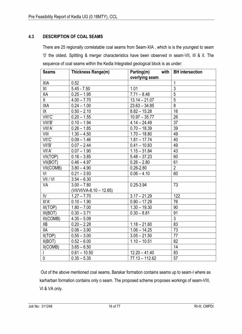
4.3 DESCRIPTION OF COAL SEAMS
There are 25 regionally correlatable coal seams from Seam-XIA , which is is the youngest to seam
‘0’ the oldest. Splitting & merger characteristics have been observed in seam-VII, III & II. The
sequence of coal seams within the Kedla Integrated geological block is as under:
Seams Thickness Range(m) Parting(m) with overlying seam
BH intersection
XIA 0.52 1
XI 5.45 - 7.50 1.01 3
XA 0.25 – 1.95 7.71 – 8.48 5
X 4.00 – 7.70 13.14 – 21.07 5
IXA 0.24 – 1.00 23.63 – 34.85 8
IX 0.50 – 2.10 8.82 – 15.28 16
VIII’C’ 0.20 – 1.55 10.97 – 35.77 26
VIII’B’ 0.10 – 1.94 4.14 – 24.49 37
VIII’A’ 0.26 – 1.85 0.70 – 18.39 39
VIII 1.30 – 4.50 1.70 – 18.80 49
VII’C’ 0.09 – 1.46 1.81 – 17.74 40
VII’B’ 0.07 – 2.44 0.41 – 10.83 49
VII’A’ 0.07 – 1.90 1.15 – 31.84 43
VII(TOP) 0.16 – 3.85 5.48 – 37.23 60
VII(BOT) 0.46 – 4.97 0.26 – 2.80 61
VII(COMB) 3.80 – 4.90 0.26-2.80 2
VI 0.21 – 3.93 0.06 – 4.10 60
VII / VI 3.54 – 6.30
VA 3.00 – 7.80 (VII/VI/VA-8.10 – 12.65)
0.25-3.94 73
IV 1.27 – 7.70 3.17 – 21.29 122
III’A’ 0.10 – 1.90 0.90 – 17.29 76
III(TOP) 1.80 – 7.00 1.30 – 19.30 90
III(BOT) 0.30 – 3.71 0.30 – 8.81 91
III(COMB) 4.35 – 5.09 3
IIB 0.20 – 2.28 1.18 – 21.60 83
IIA 0.06 – 3.90 1.06 – 14.25 73
II(TOP) 0.55 – 3.00 3.05 – 21.50 77
II(BOT) 0.52 – 6.00 1.10 – 10.51 82
II(COMB) 3.65 – 6.50 14
I 0.61 – 10.50 12.20 – 41.40 83
0 0.35 – 5.35 77.13 – 112.62 57
Out of the above mentioned coal seams, Barakar formation contains seams up to seam-I where as
karharbari formation contains only o seam. The proposed scheme proposes workings of seam-VIII,
VI & VA only.
Page 17
Pre Feasibility Report of Kedla UG (0.18MTY), CCL
Job No: 311248 17 of 77 RI-III, CMPDI
Seam V A
Seam VA occurs below Seam VI with a parting ranging from 0.25 m to 3.94 m. Average parting is
around 2.5m.The seam overlies Seam V with a parting ranging 6.70m to 47.25m. The thickness of
seam VA varies from 3.00m to 7.80m.
Depth of Intersection of Seam VA from surface:
Shallowest : 21.86m (old data)
Deepest : 159.65 m (old data)
Stratigraphic Position of Seam VA
Seam VA lies between Seam V and Seam VI.
Parting : The parting of Seam VA with underlying Seam V is 6.70 to 47.25m and with overlying
seam VI is 0.25 to 3.94m.
Splitting : No splitting reported.
Roof & Floor: Roof of the seam VA is carbonaceous shale excepting 1 borehole where it is shale
and sandy shale. The Floor of the seam is mostly carb. Shale sometimes grey shale or alternating
bands of shale and sandstone.
Incrop/ Outcrops : The Seam VA does not outcrop in the area.
Seam VI
Seam VI occurs below Seam VII Bottom with a parting ranging from 0.06 m to 4.10 m. The seam
overlies Seam VA with a parting ranging 0.25m to 3.94m. The thickness of seam VI varies from
0.21m to 3.93m.
Depth of Intersection of Seam VI:
Shallowest : 19.41m (old data)
Deepest : 154.32 m (old data)
Stratigraphic Position of Seam VI: Seam VI lies between Seam VA and Seam VII Bottom.
Parting: The parting of Seam VI with underlying Seam VA is 0.25 to 3.94m and with overlying
seam VII Bottom is 0.06 to 4.10m.
Splitting: No splitting reported.
Page 18
Pre Feasibility Report of Kedla UG (0.18MTY), CCL
Job No: 311248 18 of 77 RI-III, CMPDI
Roof & Floor: Roof of the seam VI is generally carbonaceous shale followed by grey shale,
alternating bands of sandstone and shale. The Floor of the seam is mosly carb. Shale sometimes
grey shale or alternating bands of shale and sandstone.
Seam VIII
Seam VIII is the youngest workable seam in the Kedla UGP and also is the only workable seam
whose in crop exists within the project. The seam is being mostly developed & depillared through
Mines No. 1&2. The thickness of seam VIII varies from 1.30m to 4.50m.
Status of mining : Worked seam
Depth of Intersection of Seam VIII.
Shallowest : 5.86m (old data)
Deepest : 99.57 m (old data)
Stratigraphic Position of Seam VIII : Seam VIII lies between Seam VIITop and Seam VIIIA.
Parting : The parting of Seam VIII with underlying Seam VII Top is 8.85 to 97.62m and with
overlying seam VIIIA is 1.70 to 18.80m.
Splitting : No splitting reported.
Roof & Floor: Roof of the seam VIII is mostly carbonaceous shale, & sandstone. The Floor of the
seam is mostly carb. shale, grey shale and alternating sandstone and shale and sandy shale.
Incrop/ Outcrops: The Seam VIII incrops in all the sectors in the area.
4.5 QUALITY OF COAL SEAMS CONSIDERED FOR THIS SCHEME
The seam considered in this scheme is seam-VIII, VI & VA. Seam-VA is comparatively thick and
better in quality. Seam-VI is moderately thin with low ash content.
Page 19
Pre Feasibility Report of Kedla UG (0.18MTY), CCL
Job No: 311248 19 of 77 RI-III, CMPDI
Coal Seams Sample Type Ash % GCV (kcal/kg) range (as per GR)
VIII Ex –Band
21.8 – 30.7 5846 – 6273 (8440 – 8655)
In-Band 25.6 – 45.6 5846 - 6025
VI Ex -Band 14.9 – 28.6 6230 – 7066 (8479 – 8675)
In-Band 19.0 – 30.9 5614 - 6724
V’A’ Ex -Band 21.3 – 30.8 5305 – 6482 (8543 – 8666)
In-Band 24.3 – 31.1 5734 - 6264
Note: Figures in the bracket indicates the GCV of the coal where as other figures shows the UHV of the
coal.
4.6 GEOLOGICAL RESERVE OF SEAMS CONSIDERED
The geological reserve considered for this scheme is as under:
Seam Grade Geological Reserve(M.Te)
VIII W-III to W-IV 8.075
VI W-IV 6.983
VA W-III to W-IV 21.24
Total 36.298
Page 20
Pre Feasibility Report of Kedla UG (0.18MTY), CCL
Job No: 311248 20 of 77 RI-III, CMPDI
CHAPTER-V
MINE BOUNDARIES, RESERVE & MINE LIFE
5.0 ESTIMATION OF EXTRACTABLE RESERVE
The following considerations have been adopted for estimation of extractable reserve:
a) The reserve has been estimated for the workable mining area only. No area having hard cover less
than 15m have been considered for the purpose of estimation of extractable reserve.
b) The height of extraction for the proposed mining area have been considered as full seam thickness
maximum up to 4.5m after leaving 0.6m coal in roof. Since, the immediate roof of seam-VIII, VI & VA is
of carbonaceous shale. Therefore, it is proposed to leave 0.6m coal against shale roof. The panel wise
thickness has been considered on the basis of boreholes falling within the panel or its adjoining panels
and isocore of the seams.
c) The seam wise development height and width of the gallery considered for estimation of
extractable reserve are as under :
Seam
Status of seam
Pillar Size (Existing / Proposed)
Workable seam thickness in the mining area
Existing Development Height
Proposed Dev Height (m)
Proposed Depillaring Height
Width of Gallery (Existing / Proposed)
VIII Mostly Develo
ped
28m x 28m 2.20-3.25 3.00 3.00 Full seam thickness
4.2m
VI Virgin 28m x 28m 2.0 – 3.93 Virgin 3.00 or seam
thickness
Full seam thickness
4.2m
V’A’ Partly Develo
ped
28m x 28m (Existing)
2.89 - 4.25 (Mine No-3)
3.00 3.00 Full seam Section
4.2m
28m x 28m (Existing)
3.03 – 5.39 (Mine No-1)
3.00 (partly virgin)
3.00 or seam
thickness
Full seam Thickness or max. up
to 4.5m
4.2m
Note : Proposed development height is after leaving 0.6m coal against shale roof.
Part of the property (in the west of fault F5) is mostly developed through mine no-3 of seam VA. The
Pillar size in this area is 28m x 28m with gallery width 4.20m. Seam-VI is workable over this area (in
the west of fault F5) with a parting less than 3.0m. Hence, seam VA and seam VI in this section (I,e in
the west of fault F5) are contiguous to each other. Hence the pillar in both the seams should be
vertically coincident with each other. Hence the pillar size & gallery width for development of seam VA
have been considered as that of seam VA.
Page 21
Pre Feasibility Report of Kedla UG (0.18MTY), CCL
Job No: 311248 21 of 77 RI-III, CMPDI
The part of the property of seam VA(I,e in the east of fault F5), is also developed through reverse drift
from seam-VIII having pillar size 28m x 28m with gallery width 4.2m. Hence, the pillar size & gallery
width for the remaining area where development is proposed have been considered as that of the
existing pillar size & gallery width of 28m and 4.2 respectively. The said data regarding pillar & gallery
size have been provided by the colliery during field visit.
d) The percentage of extraction for the in-situ developed pillar has been taken as 65%.of the total
in-situ pillar reserve.
e) The specific gravity of the coal has been considered as per the average grade of the coal within
the panel. The average grade has been considered based on the analyzed borehole falling within the
panel or as per isograde of the coal falling within the panel or its adjoining panels. The formula used
for determination of specific gravity is as under
Sp Gravity = 1.28 + 0.01 x Ash%
f) Reserve lost in panel barriers, due to % of extraction, barrier against fault, river, nala, and panel
barriers etc have been considered as the mining losses for the project.
g) Extractable reserves of the individual panels have been determined by multiplying the area of
the panel, average workable seam thickness( after leaving 0.6m coal against shale roof) in the panel
and specific gravity of coal of that panel , % of extraction in development for a particular pillar size
and seam thickness within the panel.
h) In mine no-3, generally roof coal more than 0.6m is left to maintain a minimum parting of 3.0m
between seam VA & VI.
i) Extractable reserves have been estimated after leaving barriers against river / nala as per
statute with due consideration of angle of draw as 30 degree.
The seam wise development and depillaring reserve for the proposed kedla underground is as
under:
Seam Extractable Reserve(M.Te)
Total Development Depillaring
VIII 0.12 0.44 0.57
VA(Mine-3) 0.43 3.20 3.63
VA(Mine-1) 0.96 2.74 3.70
VI 1.02 1.58 2.60
Total 2.58 7.96 10.54
Reserve for this Scheme
3.02 ( Development reserve of all three seams + Depillaring reserves of seam-
VIIII )
Page 22
Pre Feasibility Report of Kedla UG (0.18MTY), CCL
Job No: 311248 22 of 77 RI-III, CMPDI
Mine wise, seam wise, grade wise extractable Reserve
Mine No Seam GCV Dev Dep Total Weighted Av GCV(Kcal / Kg)
Mine No -1 VA 5758.24 0.142 0.378 0.520 5988.46
6040.72 0.82 2.360 3.18
Total Mine No-1 0.96 2.74 3.70
Mine No-3 5755.52 0.335 2.135 2.47 5844.24
6037.87 0.095 1.067 1.162
Total Mine No-3 0.430 3.203 3.63
Mine no -3 Seam-VI 6137.10 0.406 0.576
0.980 6278.81
6372.30 0.615 1.005 1.620
Total Mine No-3(Seam-VI) 1.021 1.581 2.602
Mine No-1 Seam-VIII
6044.26 0.12 0.44 0.56 60444.26
Total Extractable Reserve 2.22 7.15 9.37
5.1 ESTIMATION OF MINE LIFE
The scope of this scheme is limited to only development of seam-VI, VA & partly seam-VIII and
development and depillaring of seam-VIII (remaining part of area). The development reserve for seam-
VIII, VI & VA comes around 2.58M.Te. In the remaining part of the area of seam-VIII, the depillaring
reserve comes around 0.44M.Te. The total extractable reserve considered for this scheme comes
around 3.02 M.Te. This 3.02 M.Te extractable reserve includes development reserve of seam VIII, VA
& VI and depillaring reserve of seam-VIII.
It is proposed to work two SDL district at a time. In one SDL district there will be three SDL with two
UDM. The productivity of one SDL(as per CIL norms) has been taken as 100TPD.
Production from one SDL District : 3 x 100 = 300TP
No of districts in operation : 2
Total Production in a day : 2 x 300=600 TPD
Nominal Production in a year : 0.18 MTY
Peak Production in a year : 0.22 MTY
Estimated Production Period : 16 Year
Construction Period : 2 Year
Life of the mine including construction period: 18 Year
(Note: The existing production of Kedla UG is around 300 TPD which will continue during
construction period.)
Page 23
Pre Feasibility Report of Kedla UG (0.18MTY), CCL
Job No: 311248 23 of 77 RI-III, CMPDI
CHAPTER-VI
MINE ENTRIES
6.0 EXISTING MINE ENTRIES
Presently, the property under Kedla UG is being worked through three set of separate inclines / mines.
Seam VIII has been approached from Mine Nos. 1 & 2 while seam V-A has been approached from Mine
No. 3 and reverse drift from seam-VIII to seam VA (in the area east of fault F5 I,e in the area of mine no-
1).
In Mine No.1, seam VIII has been mostly developed & depillared except area lying below HFL of Chutua
nala. In Mine No. 1, seam V-A has also been approached from seam VIII in underground by a pair of
reverse drifts. Only part of development has been made in seam V-A.
In Mine No. 2, only seam VIII has been approached by a pair of inclines. The area in the west of fault F5
has already been developed and depillared.
In Mine No. 3, seam VA has been approached from the high wall of old quarry of Kedla OCP. The seam
is under development by B&P method.
Mine / Incline Incline Specification Existing Uses
Mine No-1
Incline no-1A Length-60m, Gradient ,1 in 8.0 Haulage
Incline no-1B Traveling
Air Shaft Dia -4.2m, Depth -10m Return
Mine No-2
Incline no-2A Length-60m, Gradient ,1 in 8.0 Haulage
Incline no-2B Travelling
Incline no-2C Return
Mine No-3
Incline no-3A Approached from Quarry Edge Haulage
Incline no-3B Travelling
Incline no-3C Return
6.2 PROPOSED MINE ENTRIES
The area of mine no-3 & mine no-1 is separated by a fault F5 having westward throw of 20m .It is
proposed to approach the area of mine no-1 from mine no-3 in seam VA with a set of three drifts
from panel III5A-18 to I5A-11.The proposed two drift will serve the purpose coal evacuation &
material supply and act as intake airway and one will act as return of mine no-1 .
Page 24
Pre Feasibility Report of Kedla UG (0.18MTY), CCL
Job No: 311248 24 of 77 RI-III, CMPDI
Seam-VI is lying around 2.5m above seam VA. In the east of fault F5, the seam-VI is not workable
due to low seam thickness. In the west of fault F5, seam-VI is workable (I,e in the mining area of
mine-3). The seam-VI in this area is contiguous with of seam-VA. Hence it is proposed to extract the
coal in both the seams simultaneously. Seam VA is mostly developed in this area and standing on
pillars. The panels of seam-VI have been proposed vertically superimposed with seam-VA with same
pillar size & gallery width. It is proposed to approach the seam-VI through set of three drifts from
trunk headings of seam-VA of mine no-3 near panel III5A-17.
The details of the various drifts & their uses are as under:
Drift from to Specification Purposes
D1 Mine-3
Seam-VA
Mine-1
Seam VA
Length-90m
Gradient-1 in4.5
Coal Evacuation / Intake
D2 Mine-3
Seam-VA
Mine-1
Seam VA
Length-90m
Gradient-1 in4. 5
Material Transport / Intake
D3 Mine-3
Seam-VA
Mine-1
Seam VA
Length-90m
Gradient-1 in4. 5
Return of the mine
D4 Mine-3
Seam-VA
Mine-1
Seam VA
Length-90m
Gradient-1 in4. 5
For Pumping from mine-1
to mine-3
D5 Mine-3,
Seam VA
Mine-3 Seam-VI Length-14m
Gradient – 1 in 4.5
Coal Evacuation from
seam-VI
D6 Mine-3,
Seam VA
Mine-3 Seam-VI Length-14m
Gradient – 1 in4.5
Material Transport for
seam-VI
D7 Mine-3,
Seam VA
Mine-3 Seam-VI Length-14m
Gradient – 1 in 4.5
Return airway for seam-VI
In addition to above drifting lump sum provision has been made for sump arrangement & other
drivages in this report.
Note : The existing mine entries is proposed to be utilized for the proposed kedla underground.
Page 25
Pre Feasibility Report of Kedla UG (0.18MTY), CCL
Job No: 311248 25 of 77 RI-III, CMPDI
CHAPTER-VII
MINING STRATEGY
7.0 MINING STRATEGY
The mining area of kedla underground has following constraints.
7.1 SURFACE CONSTRAINTS
These are the following surface constraints for the existing Kedla underground.
The Chutua nala makes the northern boundary of the mine.
Houses & Hutments of CCL are falling over the mining area of Kedla underground.
Villages & other surface infrastructures
Incrop of seam-VI& VA are extracted by opencast. In mine no-3, seam-VA has been approached
from the quarry batter.
7.2 UNDERGROUND CONSTRAINTS
Seam-VIII is mostly developed & depillared. Seam-VI & VA is lying within 60m from the floor of
seam-VIII.
Seam-VI & VA is contiguous with each other parting ranges from 2 to 3 m within the proposed
mining area.
The proposed underground mining area is traversed by three faults F5, F6 & F16.
Seam VA is manually developed along the floor of the seam and the seam has swinging floor
contour.
The immediate roof of seam VA, VI & VIII is of carbonaceous shale.
7.3 STRATEGY TO WORK IN KEDLA UNDERGROUND
a) STRATEGY TO WORK: It is proposed to utilize the existing mine infrastructure like mine entries,
surface bunker, manpower, residential & service buildings. It is proposed to introduce mechanization
with SDL for development & depillaring of seams. There will be three SDL and two UDM in a district.
There will be two districts in operation .Firstly, it is proposed to developed & depillared the remaining
few panels of seam-VIII. After completion of development & depillaring of seam-VIII, both the SDL
districts are proposed to be shifted in mine no-1 of seam-VA for its development in virgin patch. After
Page 26
Pre Feasibility Report of Kedla UG (0.18MTY), CCL
Job No: 311248 26 of 77 RI-III, CMPDI
completion of development of seam-VA in mine no-1, both the SDL districts are proposed to be
shifted for development of seam-VI in mine no-3 of seam-VA. Seam-VA & VI are contiguous with
each other; hence it is proposed to depillar the seams simultaneously maintaining a parting between
the seams as 3.0m. However, no depillaring is proposed in seam-VA & VI in this report. The pillars
and galleries of seam-VA & VI are proposed vertically coincident with each other. The pillars and
gallery widths of seam-VI are proposed as that of seam-VA to make the pillars and galleries. It is
proposed to work one seam at a time with two SDL districts to improve the work concentration and
for higher production & productivity with due consideration of safety.
b) STRATEGY FOR COAL EVACUATION : It is proposed to rationalize the coal evacuation system.
In order to rationalize the coal evacuation system, it is proposed to connect the mine no-1 & mine no-
3 with set of three drifts. Seam-VA & VIII is already connected with reverse drifts in mine no-1.Initially
when development & depillaring will be in seam-VIII, the coal extracted from the faces will be brought
to seam-VA of mine no-1 through reverse drifts with series of gate & trunk belt conveyors. From mine
no-1, the coal is proposed to bring in seam-VA of mine no-3 through drift with belt conveyors. From
mine no-3, the coal will be transported up to surface with main trunk belt conveyor. The centralized
coal evacuation system have been proposed in this report from mine no-3.Coal extracted from
seam-VI is proposed to bring in seam-VA through staple pit or belt in drift and finally up to surface
with the main trunk belt in seam-VA.
c) STRATEGY FOR PUMPING : Since, the overlying seam-VIII, in majority of the area in mine no-1
is depillared with caving. The dip most point in the developed area is below HFL. Hence, borehole for
pumping can not be made in the HFL area. Outside the HFL of seam VIII, borehole for pumping may
be done. The main sump for seam-VIII in mine no-1 area will be in the trunk roadway of that seam.
There fore it is initially proposed that while development and depillaring of the remaining part of seam
–VIII, water will be collected at the main sump in trunk heading of seam-VIII and accumulated water
will be pumped out in to chutua nala through settling tank(after proper treatment) through borehole
pumping . The existing pumps of seam-VIII are proposed to be utilized for the purpose. After
depillaring of seam-VIII in mine no-1, borehole pumping will not be practically possible through
goaved out area, hence, incline pumping have been proposed for the remaining life of the mine.
While development of seam-VA, the pumping of seam-VA in mine up to the trunk heading & panel-
I5A-7, the pumping will continue with existing pumping system. After development of panel I5A-7,
one drift has been proposed from mine no-1 to mine no-3 in seam-VA. Through this drift, it is
Page 27
Pre Feasibility Report of Kedla UG (0.18MTY), CCL
Job No: 311248 27 of 77 RI-III, CMPDI
proposed that the water collected at the main sump of seam-VA in mine no-1 area will be pumped
into mine no-3 in seam-VA main sump, from where the accumulated water will be pumped out up to
surface through inclines. Accordingly provisions have been made in this report.
While working in seam-VI in mine no-3 area, the water collected in the seam is proposed to bring to
main sump of seam-VA of mine no-3 through staple pit, from where water will be pumped out to
surface through inclines.
The pumping in seam-VA for both mine no-1 & mine no-3 will continue to prevent from water logging.
Accordingly provisions have been made in this report.
c) STRATEGY FOR MAN & MATERIAL SUPPLY : In case of seam-VIII, existing
haulage of mine no-1 is proposed to be utilized for material supply from surface to underground trunk
roadway. From trunk roadway various endless haulages have been proposed for material supply up
to working districts.
In case of seam-VA & VI, existing haulage of mine no-3 is proposed to be utilized for material supply
from surface to underground trunk roadway. From trunk roadway various endless haulages have
been proposed for material supply up to working districts.
Man riding system is proposed for man transport from surface to underground for seam VA, VI & VIII.
The shifting of man riding system may be required .
d) STRATEGY FOR VENTILATION: Existing air shaft in mine no-1 is proposed to be utilized for
return airways for seam-VIII, mine no-1 area. In case of seam-VA & VI development, existing fan
installation of mine no-3 is proposed to be utilized for return airway to rationalize the manpower
deployment. However, it is proposed to conduct ventilation study with the revised layout of the mine
and the recommendations of the ventilation study should be complied effectively for proper
ventilation of the mine.
e) STRATEGY FOR WORKING WITH SURFACE CONSTRAINTS: In case of chutua nala, a barrier
against HFL of Chutua nala is left as per statute along with considering angle of draw of 30 degree.
No working is proposed below HFL except prior permission of DGMS. In case of Seam-VIII, pillars
are already developed below HFL. Beyond HFL, a small patch of seam-VIII may be workable after
leaving the barrier against HFL, which can be approached only through developed workings below
HFL. Hence, prior to work this small patch, DGMS permission is proposed to be obtained. In case of
other seams like seam-VA & VI , no working is proposed below HFL and within the barrier left
against HFL.
Page 28
Pre Feasibility Report of Kedla UG (0.18MTY), CCL
Job No: 311248 28 of 77 RI-III, CMPDI
A barrier against the boundary of house & hutments considering angle of draw of 30 degree have
been left. No depillaring is proposed below houses & hutments and villages in the mining area of
kedla underground. However this report envisages only development of seam-VA & VI. But while
depillaring of seam-VIII , the said precautions is to be taken.
f) STRATEGY TO WORK WITH UNDERGROUND CONSTRAINTS :
Mine No-1: The parting between seam-VA & VIII is generally less than 60m except borehole no
CMK-120 & NCVBK-04) in mining area of mine no-1. These two boreholes show parting between
seam-VIII & VA 67m and 62m respectively. The depillaring of seam-VIII in the mining area of mine
no-1 is extracted using wide & stall method to protect the surface features. Hence, it is almost sure
that the area where wide & stall method have been used will be completely filled with water. This
attracts Reg 127 of CMR 1957. Therefore, it is proposed that while depillaring of the panels in
underlying seam-VA & VI, dewatering of overlying panels in seam-VIII should be ensured by putting
long boreholes in roof through burn side boring machine. However, no depillaring is proposed in
these underlying seams in this report. If any abnormal seepage is observed while development in
underlying seams, the thickness of parting & reasons for abnormal seepage should be checked by
putting lone hole with burn side boring equipment .Accordingly, provision of burn side boring machine
and additional pumping provisions has been made in this report for safe and secure mining.
Mine no-3: The parting between seam-VA & VIII is generally less than 60m in mining area of mine
no-3. Parting between seam-VIII & VA and between seam-VIII & VI varies from 58.77m to 48.35m
and 54.85m to 42.05m respectively. This attracts Reg 127 of CMR 1957. Therefore, it is proposed
that while depillaring of the panels in underlying seams, dewatering of overlying panels in seam-VIII
should be ensured by putting long boreholes in roof through burn side boring machine. However, no
depillaring of underlying seams in this mine area have been proposed in this report.
The proposed mining area is traversed by three faults. A barrier of 20m has been proposed to be left
on either side of the fault for safety reasons.
Page 29
Pre Feasibility Report of Kedla UG (0.18MTY), CCL
Job No: 311248 29 of 77 RI-III, CMPDI
CHAPTER-VIII
METHOD OF MINING
8.0 METHOD OF MINING
8.1 APPROACH TO SEAMS: The existing inclines of mine no-1 & 3 are proposed to be
utilized as mine entries for the seams.
8.2 TRUNK ROAD DEVELOPMENT IN SEAMS : The existing trunk road developed in seam-VIII
& VA is proposed to be utilized for the seams. The parting between seam-VI & VA in the mining area
of mine no-3, varies from 1.08m to 2.75m (based on randomly selected boreholes within the mining
area). Hence, it is proposed that pillars & galleries of the trunk heading of seam-VI will be vertically
superimposed to the gallery and pillar sizes of seam VA.
8.3 PANEL DEVELOPMENT IN SEAMS : In case of already developed seams paneling
have been proposed considering its natural panel barrier left while development of seams. In case of
virgin seams five heading self draining panels have been proposed in accordance with existing pillar
sizes from centre to centre and gallery width of the seams. Since, seam-VI & VA are contiguous, the
superimposed panels of seam-VI & VA have been proposed in this report.
8.4 METHOD OF MINING : Bord & Pillar with SDL
8.5 MINING PARAMETERS : The seam wise mining parameters within the considered
mining area of the proposed Kedla underground are as under:
Seam-VIII
i) Depth of the panels from Surface : 6m-100m( Mine No-1) & 9.36m – 77.08m( Mine no-3)
ii) Seam thickness : 2.08m to 3.0m ( Mine no-1) &1.97m to 3.03m ( Mine no-3)
iii) Av. pillar size (Centre to Centre) : 28m x 28m ( Center to centre)
iv) No. of Headings in a panel : 5 headings
v) Panel width : up to 153m
vi) Panel length : up to 850 m
vii) Development height : seam thickness (>1.5m) up to 3.0m
viii)Extraction height : Full seam thickness or max. 4.50m
Page 30
Pre Feasibility Report of Kedla UG (0.18MTY), CCL
Job No: 311248 30 of 77 RI-III, CMPDI
ix) Roadway / gallery width : 4.2m (Existing)
( Note : The seam is mostly developed & Depillared within the leasehold of Kedla underground
except a small patch in the mining area of Mine No-1. Hence, the proposed pillar sizes are as per the
size of existing developed pillars and gallery sizes are as per the existing gallery size of seam-VIII).
Seam-VI
i) Depth of the panels from Surface : 59.98m-137.85 m (Mine No-1)
& 40.91 m – 133.24 m ( Mine no-3)
ii) Seam thickness : 0.21m to 1.37 m ( Mine no-1)
2.10m to 3.93m ( Mine no-3)
iii) Av. pillar size (Centre to Centre) : 28m x 28m ( Center to centre)
iv) No. of Headings in a panel : 5 headings
v) Panel width : up to 153m
vi) Panel length : up to 850 m
vii) Development height : seam thickness (>1.5m) up to 3.0m
viii) Extraction height : Full seam thickness or max. 4.50m
ix) Roadway / gallery width : 4.2m (Existing)
( Note : The seam is virgin and it is contiguous with seam-VA in mine no-3 area. Seam-VI is
workable in the mining area of mine no-3 only. Hence, the proposed pillar sizes of seam-VI are as
per the size of existing developed pillars and gallery sizes of seam-VA).
Seam-VA
i) Depth of the panels from Surface: : 60.44m-140.94 m( Mine No-1)
46.24 m –138.06 m( Mine no-3)
ii) Seam thickness : 3.03m to 5.86 m ( Mine no-1)
4.16m to 5.01m ( Mine no-3)
iii) Av. pillar size (Centre to Centre) : 28m x 28m ( Center to centre)
iv) No. of Headings in a panel : 5 headings
v) Panel width : Max up to 153m
vi) Panel length : up to 850 m
vii) Development height : seam thickness (>1.5m) up to 3.0m
viii) Extraction height : Full seam thickness or max. 4.50m
ix) Roadway / gallery width : 4.2m (Existing)
( Note : The seam is partly virgin in mine no-1 &3 area. In part of the area it is developed having pillar
sizes 28m x 28m with gallery size 4.2m. Hence to maintain the uniformity of pillar sizes, the pillar size
proposed for the virgin area is as that of existing developed pillar size.)
Page 31
Pre Feasibility Report of Kedla UG (0.18MTY), CCL
Job No: 311248 31 of 77 RI-III, CMPDI
8.6 METHOD OF PANEL DEVELOPMENT
Panel Layout: It is proposed to develop trunk roadways & working panels with 5-heading/galleries,
having pillar size as suggested above. The heading would be joined at regular intervals, at a
distance equal to applicable pillar size, by driving level galleries along dip-rise. It is proposed for
uniform pillar size. The pillar size will be 28m (centre to centre) & gallery width will be of 4.2m. During
development of a panel, gallery height would be the seam height or maximum 3.0m where thickness
is more than 3.0m.
System of Panel Development: It is proposed to develop 5-headings in a panel with a view to
optimise the resources utilisation in achieving higher production. Total available faces would vary
from 9-11 (depending on the face position). Depending upon the number of equipment, the
distribution of work load in headings may be as follows:
Three faces for dressing ,drilling & supporting operation
Three faces for charging and blasting
Three faces under loading operation by SDL
Remaining faces for other production & safety related works.
Sequence of operations during panel development: The B&P panel consists of a number of faces
where activities essentially consisting of Coal Preparation, Supporting & Coal Loading are required to
be performed. The sequence of operation is cyclic and requires sequential operations/activities of
drilling, charging & stemming, blasting, fume clearance, dressing & supporting, coal
loading/evacuation by SDL, cleaning/dressing and preparing for next cycle of operation.
Simultaneously, different operations/activities are continued at different faces. Considering the
manpower and face equipment, the different activities are needed to be optimised for enhanced
production and productivity.
The winning of coal would be done by” drilling and blasting off the solid”
Drilling would be done by the drilling crew using UDM (Universal Drilling Machine)
Drilling pattern would be such to achieve maximum pull in a blast.
After completion of drilling, the shot holes will be charged by explosives (permitted) followed by
appropriate stemming (compaction) for efficient blasting by the shot firing crew.
Coal is blasted off-the-solid by the shot firer after alerting & withdrawing the manpower from the
faces.
Page 32
Pre Feasibility Report of Kedla UG (0.18MTY), CCL
Job No: 311248 32 of 77 RI-III, CMPDI
After blasting of the faces, it should be cleared from the blasting fumes by appropriate ventilation
by auxiliary fan before re-entering the face, properly dressed, & supported as per approved
‘Systematic Support Plan’.
Holes for support and coal preparation shall be drilled by UDM.
The green unsupported roof at faces is supported. This is necessary for safe working of person
& equipment under supported area. Supporting of green roof should be done by roof bolting.
The faces are then examined for misfires, blown out shots/ blown through shots etc and
condition of roof and sides after blasting.
If any misfire occurs, it should be carefully dealt as per CMR 1957.
Blasted coal would be loaded by SDL on to link / face conveyor which will further discharge on to
the Gate Belt conveyor.
Development Height & Horizon: As the seam thickness in the property proposed for B&P with SDL
is generally more than 3.0m in seam-VA , the development height for seam VA have been proposed
as 3.0m or its full seam thickness(where seam thickness is less than 3.0m). It is proposed to make
the panel development along floor of the seam.
In case of seam VI & VIII, the seam thickness is generally varying from 2.0m to 4.0m. Therefore, the
development heights for seam VI & VIII have been proposed as 3.0m or its full seam thickness
(where seam thickness is less than 3.0m). It is proposed to make the panel development along floor
of the seam. The immediate roofs of the seams are generally carbonaceous shale. Hence, for safe
working, it is proposed to leave 0.6m coal in the roof. This will result the reduction of extractable
seam thickness. Accordingly development reserve of the seams has been estimated in this report.
8.7 METHOD OF PANEL EXTRACTION : Depillaring of panels has been proposed only for seam-
VIII in mine no-1. In other seams only development is proposed with the assumption that the
developed pillar will be extracted by opencast which will provide better coal recovery in comparison
to depillaring by underground mining method. In seam-VIII, most of the area is depillared. Only a
patch is left for development & depillaring. Therefore depillaring of seam-VIII in remaining area has
been proposed.
Once the panel is developed up to the end of the panel (mine boundary), the extraction of the
developed pillar would be commenced from the dip most boundary or end of the panel and gradually
retreats towards the main / auxiliary trunk headings. The equipments, which are proposed for panel
development, will be used for the extraction of the pillars (for seam-VIII only). Extraction of pillars
Page 33
Pre Feasibility Report of Kedla UG (0.18MTY), CCL
Job No: 311248 33 of 77 RI-III, CMPDI
below surface features and within its safety barriers are not proposed. While extracting the pillars,
diagonal line of extraction is proposed to be followed.
Panel Layout & system of extraction: The panel layout & system of pillar extraction would remain
same as followed in traditional pillar extraction for Bord & Pillar technology with SDL. During
depillaring operation, each developed pillar would be splitted in two equal parts by driving a split
gallery along the level / strike, having width of gallery 4.2m.The split pillar on dip side would be
extracted first from the split gallery by slicing method. The last part of the split pillar on rise side
would be extracted from the original gallery.
Sequence of operation in Pillar Extraction:
For depillaring, firstly splitting of the original pillar is to be done by driving the split gallery of the
dimension same as original gallery
The operation of splitting of pillars may extend up to maximum of two pillars ahead of the
diagonal line of extraction (i.e, two pillars ahead of pillar under attack).
The split pillar would be extracted by slicing. The dimension of the slices should not be less than
the dimension of the split gallery. The width of rib pillar between two slices may be 1.8 –2.0m against
goaf. The number of slices in a split pillar will be 3 or more depending upon the pillar size. While
retreating, these ribs may be judiciously reduced during extraction of split pillar.
The depillaring of pillar in a SDL panel may be executed by maintaining the diagonal line of
extraction (preferably 45o).
The panel would be preferably extracted by retreating from dip to rise.
During depillaring, the working faces would comprise of split faces and slices. At each working faces,
the mining operation is of cyclic nature and consists of same activities during development
(described earlier).
8.8 FACE EQUIPMENT
The list of equipment in a SDL panel may be as under:
SDL (Side Discharge Loader) : 3
(Low Height SDL)
UDM (Universal Drilling Machine) : 2
(Low Height UDM)
Electric Rotary Coal Drill : 1 (stand bye)
Page 34
Pre Feasibility Report of Kedla UG (0.18MTY), CCL
Job No: 311248 34 of 77 RI-III, CMPDI
Portable Bolter : 1 (stand bye)
Link Conveyor : 3
Auxiliary Fan : 2
Face Pump : 2
Other equipment like Endless haulage, Gate Belt Conveyor etc would be working in the panel for
uninterrupted operation within the panel. Two SDL panel will be worked simultaneously having three
SDL & two UDM in each panel.
(Note: As per GR of the block, the seam gradient within the mining area varies 5 degree to 10 degree
where as the seam gradient provided by the project varies from 1 in 7.3 to 9.7. As per the colliery
data and GR data this property may be suitable for deployment of LHD / CM also. Presently, the
development is in progress with SDL in seam VA. As per discussion with the project official ,
HoD(Env & Forest),CCL & Regional director, it was said by the project authority & HoD(Env &
Forest),CCL that the seams where present underground working is going on with SDL is already
considered in the proposed kedla opencast ( 6.0MTY) and it will be extracted by opencast. Since,
kedla underground is an existing running underground mines and it can not be stopped immediately.
Hence, prepare a feasibility report for the kedla underground with some additional SDL having target
capacity of the project around 0.18 MTY with peak production of 0.22 MTY. The same have been
communicated in form-I of Kedla underground for EMP approval. Accordingly report has been
prepared for kedla underground.)
8.9 SUPPORT SYSTEM : As per data provided in mine capacity assessment of Kedla
underground, the RMR of seam-VA is 42.4 & 52.8. Considering lower value of RMR, the support
requirement with cement capsule and resin has been analyzed and it is found that bolting with resin
will require less no of bolts than cement capsule. The cost of bolting per tone of coal is lesser in case
of bolting with resin. Therefore roof bolting with resin capsule have been proposed in this scheme.
A. Bolts Requirement at different location with cement capsule
Particulars Gallery
Width(m) RMR
Rock Load(Te/sqm)
Row & Bolt Spacing(m)
No. of bolts/row
Strength/bolt(Te) for 22mm rod
Factor of
Safety
Permanent Roadways Junction 4.2 42.4 4.53 1.2 4 13 2.28
Permanent Roadways 4.2 42.4 4.53 1.2 4 13 2.28
Temporary Gallery 4.2 42.4 4.53 1.2 4 13 2.28
Page 35
Pre Feasibility Report of Kedla UG (0.18MTY), CCL
Job No: 311248 35 of 77 RI-III, CMPDI
Temporary Roadways Junction 4.2 42.4 4.53 1.2 4 13 2.28
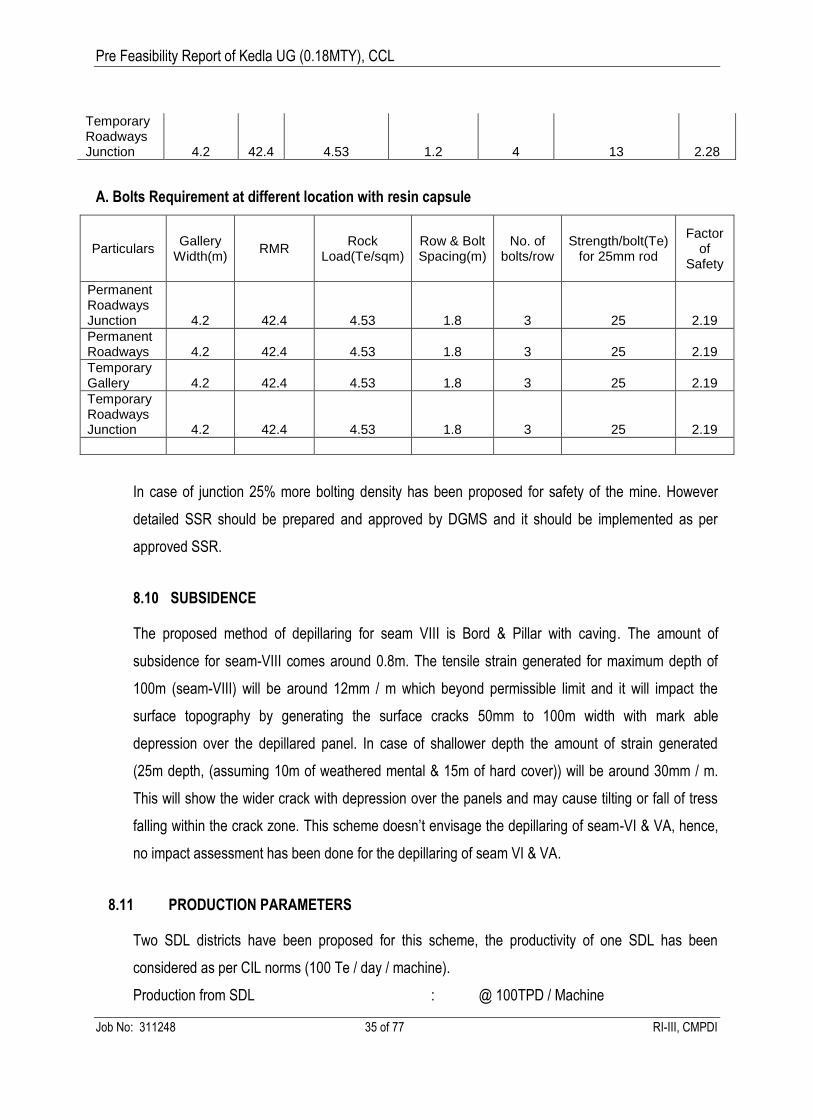
A. Bolts Requirement at different location with resin capsule
Particulars Gallery
Width(m) RMR
Rock Load(Te/sqm)
Row & Bolt Spacing(m)
No. of bolts/row
Strength/bolt(Te) for 25mm rod
Factor of
Safety
Permanent Roadways Junction 4.2 42.4 4.53 1.8 3 25 2.19
Permanent Roadways 4.2 42.4 4.53 1.8 3 25 2.19
Temporary Gallery 4.2 42.4 4.53 1.8 3 25 2.19
Temporary Roadways Junction 4.2 42.4 4.53 1.8 3 25 2.19
In case of junction 25% more bolting density has been proposed for safety of the mine. However
detailed SSR should be prepared and approved by DGMS and it should be implemented as per
approved SSR.
8.10 SUBSIDENCE
The proposed method of depillaring for seam VIII is Bord & Pillar with caving. The amount of
subsidence for seam-VIII comes around 0.8m. The tensile strain generated for maximum depth of
100m (seam-VIII) will be around 12mm / m which beyond permissible limit and it will impact the
surface topography by generating the surface cracks 50mm to 100m width with mark able
depression over the depillared panel. In case of shallower depth the amount of strain generated
(25m depth, (assuming 10m of weathered mental & 15m of hard cover)) will be around 30mm / m.
This will show the wider crack with depression over the panels and may cause tilting or fall of tress
falling within the crack zone. This scheme doesn’t envisage the depillaring of seam-VI & VA, hence,
no impact assessment has been done for the depillaring of seam VI & VA.
8.11 PRODUCTION PARAMETERS
Two SDL districts have been proposed for this scheme, the productivity of one SDL has been
considered as per CIL norms (100 Te / day / machine).
Production from SDL : @ 100TPD / Machine
Page 36
Pre Feasibility Report of Kedla UG (0.18MTY), CCL
Job No: 311248 36 of 77 RI-III, CMPDI
Production from each panel with three SDL : 3x100 TPD = 300TPD
Production from SDL Districts with two panels : 2x300TPD = 600TPD
Total SDL production from the project : 0.18 MTY (600TPD)
Peak production from the project : 0.22 MTY (733 TPD)
8.12 SCHEDULE OF SDL PROCUREMENT
The SDL procurement schedule is as under:
Sl.
No.
Particulars
of Major
Equipment
Population Year of Phasing
Existing New Y1 Y2 Y3 Y4 Y5
1. SDL
Set-1
4 4
2. SDL
Set-2
Nil 2 2
8.13 PRIOR PERMISSION REQUIRED FROM DGMS
a) Permission to work below HFL
b) Permission to work contiguous property.
c) Permission for depillaring of panels in seam-VIII.
Page 37
Pre Feasibility Report of Kedla UG (0.18MTY), CCL
Job No: 311248 37 of 77 RI-III, CMPDI
CHAPTER-IX
MINING SCHEDULE
9.0 PRODUCTION SCHEDULE
The production schedule of Kedla underground is as under:
Year Mine / Seam
Production (MTY)
Av. GCV (Kcals / Kg)
Year Mine / Seam
Production (MTY)
Av. GCV (Kcals / Kg)
1 Mine No-1 / Seam-VIII
0.09( Existing) 6044.26 11 Mine no-3 / seam VA
0.18 5844.24
2 0.09(Existing) 12 Mine No-3 / Seam-VI
0.18 6298.09
3 0.14 13 0.18
4 0.18 14 0.18
5 0.18 15 0.18
6 Mine No-1 / Seam VA
0.18 5976.86 16 0.18
7 0.18 17 0.18
8 0.18 18 0.18
9 0.18
10 Mine no-3 / seam VA
0.18 5844.24 Total 3.02
(The average GCV of the seam shows the weighted average GCV of that particular seam)
9.1 ROM QUALITY
The ROM quality of coal produced from the mine will boe of W-III & W-IV.( having ash% from 24 to
30%). Year-wise ash percentage wise coal production is shown in above table. The mine wise seam
wise weighted average GCV of the ROM coal produced from the proposed kedla underground is as
under :
S.N Mine Seam Average GCV(Kcal/kg)
1 Mine No-1 Seam-VIII 6044.26
2 Mine No-1 Seam-VA 5976.86
3 Mine No-3 Seam-VA 5844.24
4 Mine No-3 Seam-VI 6298.09
Page 38
Pre Feasibility Report of Kedla UG (0.18MTY), CCL
Job No: 311248 38 of 77 RI-III, CMPDI
CHAPTER-X
UNDERGROUND TRANSPORT
10.0 UNDERGROUND TRANSPORT
Centralized coal evacuation system has been proposed in this report. It is proposed to connect mine
no-1 & mine no-3 with set of drifts in seam VA for coal evacuation and material supply. Seam VA in
mine no-1 area is already connected with reverse drift from seam-VIII. It is proposed to evacuate the
coal produced from seam-VIII (development & depillaring both) with series of belt conveyors via
reverse drift & drift connecting mine no-1 & mine no-3 from mine no-3 main trunk belt conveyor. It is
proposed to evacuate the entire coal produced from seam VIII, VI & VA from mine no-3 centrally.
10.1 COAL EVACUATION SYSTEM FOR SEAM-VIII: The link belts of the panel will discharge
coal on to the gate belt of the individual districts. Gate belt of the panels will discharge coal on to the
trunk belt of the seam. This trunk belt will discharge coal on to belt of the reverse incline belt. This
reverse incline belt will discharge coal on to the belt installed in the trunk headings of seam-VA in
mine no-1 & it discharges the coal on to conveyor belts in drift connecting mine no-1 & mine no-3
with the help of reclaiming belt. This drift belt will discharge the coal on to the trunk belt of mine no-3
which will finally discharge on to surface bunker conveyor and finally in to surface bunker.
10.2 COAL EVACUATION SYSTEM FOR SEAM-VA (MINE -1): The link belts of the panel will
discharge coal on to the gate belt of the individual districts. Gate belt of the panels will discharge coal
on to the trunk belt of the seam. This trunk belt will discharge coal on to the belt installed in the drift
connecting mine no-1 & mine no-3 with the help of reclaiming belt. This drift belt will discharge the
coal on to the trunk belt of mine no-3 which will finally discharge on to surface bunker conveyor and
finally in to surface bunker.
10.3 COAL EVACUATION SYSTEM FOR SEAM-VI (MINE-3): The link belts of the panel will
discharge coal on to the gate belt of the individual districts. Gate belt of the panels will discharge coal
on to the trunk belt of the seam. This trunk belt will discharge the coal on to the trunk belt of mine no-
3 through staple pit which will finally discharge on to surface bunker conveyor and finally in to
surface bunker.
Page 39
Pre Feasibility Report of Kedla UG (0.18MTY), CCL
Job No: 311248 39 of 77 RI-III, CMPDI
10.4 COAL EVACUATION SYSTEM SEAM-VA (MINE -3): The link belts of the panel will discharge
coal on to the gate belt of the individual districts. Gate belt of the panels will discharge coal on to the
trunk belt of the seam. This trunk belt will discharge the coal on to the main trunk belt of mine no-3
which will finally discharge on to surface bunker conveyor and finally in to surface bunker.
Proposed Belt parameters: The proposed sizes of gate and trunk belt conveyor for coal evacuation
are of 1000mm. Link belts have been proposed as 800mm width. The details of the belts have been
given in the concerned appendices of the report.
Bunker Capacity : No underground bunker has been proposed in this scheme. One shift
coal storage capacity in bunker (2 x 100Te capacities) has been proposed at surface.
Page 40
Pre Feasibility Report of Kedla UG (0.18MTY), CCL
Job No: 311248 40 of 77 RI-III, CMPDI
CHAPTER-XI
MINE VENTILATION
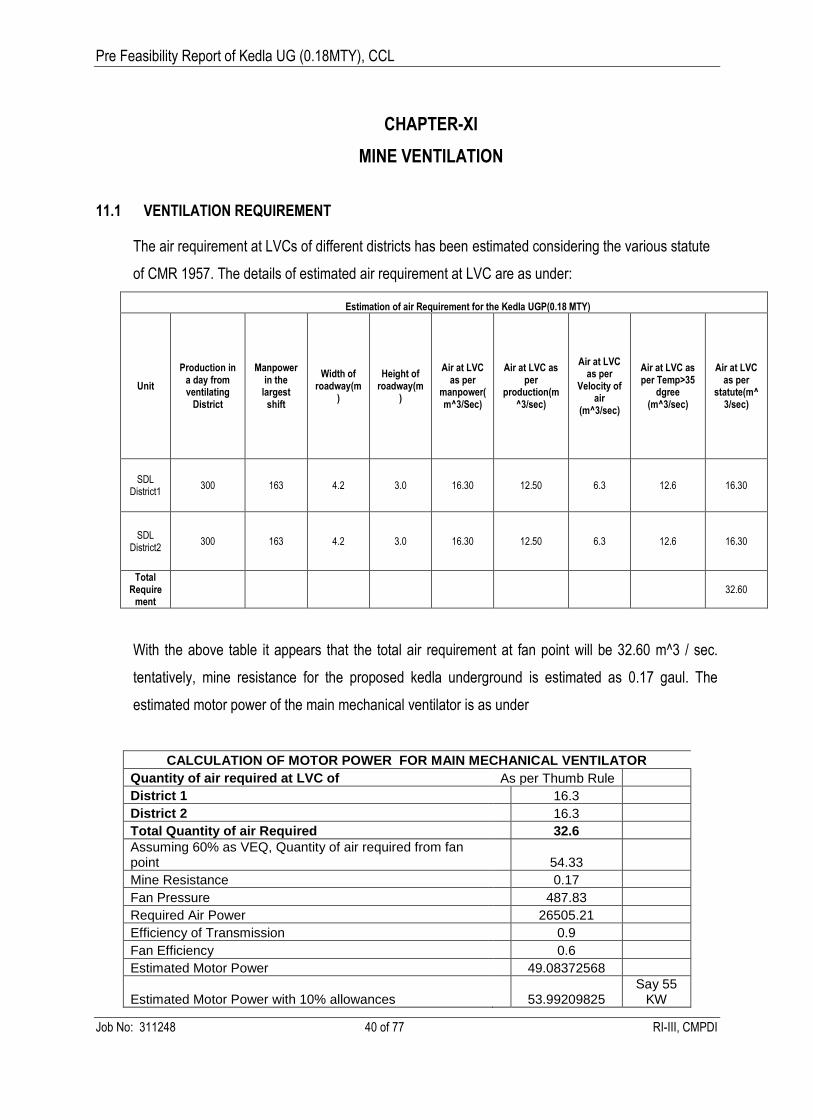
11.1 VENTILATION REQUIREMENT
The air requirement at LVCs of different districts has been estimated considering the various statute
of CMR 1957. The details of estimated air requirement at LVC are as under:
Estimation of air Requirement for the Kedla UGP(0.18 MTY)
Unit
Production in a day from ventilating
District
Manpower in the
largest shift
Width of roadway(m
)
Height of roadway(m
)
Air at LVC as per
manpower(m^3/Sec)
Air at LVC as per
production(m^3/sec)
Air at LVC as per
Velocity of air
(m^3/sec)
Air at LVC as per Temp>35
dgree (m^3/sec)
Air at LVC as per
statute(m^3/sec)
SDL District1
300 163 4.2 3.0 16.30 12.50 6.3 12.6 16.30
SDL District2
300 163 4.2 3.0 16.30 12.50 6.3 12.6 16.30
Total Require
ment 32.60
With the above table it appears that the total air requirement at fan point will be 32.60 m^3 / sec.
tentatively, mine resistance for the proposed kedla underground is estimated as 0.17 gaul. The
estimated motor power of the main mechanical ventilator is as under
CALCULATION OF MOTOR POWER FOR MAIN MECHANICAL VENTILATOR
Quantity of air required at LVC of As per Thumb Rule
District 1 16.3
District 2 16.3
Total Quantity of air Required 32.6
Assuming 60% as VEQ, Quantity of air required from fan point 54.33
Mine Resistance 0.17
Fan Pressure 487.83
Required Air Power 26505.21
Efficiency of Transmission 0.9
Fan Efficiency 0.6
Estimated Motor Power 49.08372568
Estimated Motor Power with 10% allowances 53.99209825 Say 55
KW
Page 41
Pre Feasibility Report of Kedla UG (0.18MTY), CCL
Job No: 311248 41 of 77 RI-III, CMPDI
The existing kedla underground has two main mechanical ventilator installed in mine no-1 & mine no-
3. The fan installed in the existing kedla underground is as under:
Mine / Incline Fan Type Location of Fan
Mine No-1 PV200 In Air Shaft up to Seam-VIII
Mine No-3 PV 160 In Incline up to seam-VA
The existing fan of kedla underground will meet the requirement of proposed kedla underground.
Hence, no provision has been made in this scheme for main mechanical ventilator. However, a lump
sum provision has been made in this scheme for rationalization of ventilation. However, fresh
ventilation study has been proposed in this scheme to improve the ventilation efficiency.
11.2 PROPOSED VENTILATION SYSTEM
While working in seam-VIII, the existing ventilation system will continue. The return of seam-VIII will
be through airshaft of mine no-1. In case of seam-VI & VA working, it is proposed that the return of
seam-VA will be through mine no-3. The fan installed at 3C incline of mine no-3 will serve as the
return for mine no-1 & mine no-3. A drift connecting mine no-1 & mine no-3 has been proposed in
this report. However, the detailed ventilation study is proposed in this report.
Page 42
Pre Feasibility Report of Kedla UG (0.18MTY), CCL
Job No: 311248 42 of 77 RI-III, CMPDI
CHAPTER-XII
WATER MANAGEMENT, PUMPING & DRAINAGE
12.1 INTRODUCTION
The Pre-feasibilty report for the proposed Kedla underground mine has been planned for targeted
production of 0.18 MTY of coal. The tentative estimate for the make of water has been done on the
basis of rain fall and natural inflow of ground water. The pumping system for the project has been
proposed accordingly.
12.2 ESTIMATION OF QUANTITY OF WATER FOR PUMPING
12.2.1 Source of water
The different source of water inflow into this project is as under:
i) Percolation of water due to rain fall within the surface area of the proposed UG.
ii) Seepage of water from the strata/ ground water.
iii) Seepage due to goaved out working of seam-VIII.
iv) Percolation of water due to spraying at coal faces .
12.2.2 General Consideration / Assumption
The following assumptions and available data of the proposed mine :
a) The maximum rainfall in the mine area during the monsoon period.
b) The average rainfall during the monsoon has been considered as 9.97mm per day. The
average rainfall during monsoon period i.e. 4 months (120 days) has been taken as basis of
calculation.
c) It is presumed that 33% (1/3 rd) of rain water falling in the catchments area will percolate
down the mine after evaporation and natural drainage.
d) Natural make of water is assumed to be 10% of the percolation due to rain fall and proximity
of nearby Chutua nala.
e) Percolation of rain-fall water for the area of caving due to depillaring which has been
proposed during period of operations.
f) Catchments area has been considered as 3.33 Sq.km.
Page 43
Pre Feasibility Report of Kedla UG (0.18MTY), CCL
Job No: 311248 43 of 77 RI-III, CMPDI
g) Pumping system to be capable of pump out 24 hours make of water in effective 18 hours of
pumping.
12.3 MAKE OF WATER
The make of water for the proposed kedla underground is around 753 cum/hr (208lps). Pumping
system has been proposed accordingly.
12.4 PUMPING CAPACITY
The proposed pumping capacity is 240lps.
12.5. PROPOSED PUMPING SYSTEM
Face pump will discharge water into the main sump. From main sump water will be discharged in to
surface through inclines via settling tank. Accordingly provisions have been made in this report.The
seam wise pumping system is as under:
Seam-VIII : The existing pumping arrangement of the mine no-1 will continue till its
exhaustion.
Seam-VA : The centralized pumping from mine no-3 is proposed. The water accumulated in the
main sump of seam-VA of mine no-1 will be discharged in to main sump of seam-VA in mine no-3
through drift. From main sump of seam –VA in mine no-3, water will be pumped out to surface
through inclines. Accordingly provisions have been made in this report.
Seam-VI : Water accumulated in the main sump of seam-VI will be brought in to the main sump of
seamVA in mine no-3 through staple pit and it will be finally pumped out to surface through inclines
of seam-VA in mine no-3.
Note : Some of the additional pumps have been proposed in this report. Where as the existing
pumps are also proposed to be utilized for the project.
Page 44
Pre Feasibility Report of Kedla UG (0.18MTY), CCL
Job No: 311248 44 of 77 RI-III, CMPDI
CHAPTER-XIII
COAL HANDLING PLANT & DESPATCH
13.1 INTRODUCTION
Kedla UG mine has been planned for target capacity of 0.18 mty. The coal handling plant shall have
facilities for receiving coal from main incline conveyor, conveying, storing and loading into tipping
trucks for onward transportation to kedla washery. The coal handling plant will also have been
provided with suitable running repair facilities.
13.2 DESIGN PARAMETERS:
The Coal Handling Plant has been designed based on coal production as well as following factors
have been considered for finalising the location of the CHP.
a. Incline Mouth
b. Topography
c. Mine boundary
d. Loading point
e. Overall economy of the system.
13.3 BASIC DATA
The following data have been considered while formulating the coal handling plant :
Particulars Data
Production capacity of the project (ultimate) MTY : Nominal-0.18mty,
Peak-0.22 mty
No. of working days considered / year : 300
No. of working shifts / day : 3
No. of effective working hours / shift : 5
Quality and other parameters of coal
Average Grade of coal : W-III / W-IV
Feed size of coal to the coal handling plant(mm) : ROM form SDL
Mode of despatch : Truck
Consumer : Kedla washery
Page 45
Pre Feasibility Report of Kedla UG (0.18MTY), CCL
Job No: 311248 45 of 77 RI-III, CMPDI
Loading hours/day : Round the clock
Life of the project (years) : 18 years
13.4 SYSTEM CAPACITY
The system capacity of the coal handling plant have been designed in such a way so that it can
handle fluctuations in the coal production within an overall rated production of all the three seams
from the mine. There is sufficient cushion to absorb fluctuations in coal production.
13.5 DESCRIPTION OF CHP
The CHP shall have the following important units :
a) Receiving arrangement of underground coal
b) Storage of coal in over head hoppers
c) Load out System (Truck loading arrangement)
d) Dust suppression, plant safety, fire fighting system etc.
e) Road weigh bridge.
13.5.1 RECEIVING ARRANGEMENT OF COAL
The main incline conveyor will feed coal to the receiving transfer house. From this receiving house,
coal will be given onward to receiving surface hoppers.
13.5.2 STORAGE & RECLAMATION
The coal from transfer house at coal touch point will be reclaimed for onward despatch to 2x100te
overhead hoppers by 1000mm conveyor.
13.5.3 LOADING & DESPATCH
Surface CHP will comprise of two numbers of truck loading hoppers of 100 te capacity each fitted
with motorised sector gate below the hoppers. Ground stock storage has also been provided at the
end of the elevating conveyor of the CHP. The coal will be loaded into the truck below the hoppers
with the help of motorised sector gate. From ground stock coal will also be loaded to the trucks by FE
loader for onward transportation of coal to nearby kedla washery. General arrangement of Truck
loading hoppers is given in drawing nos. R3-E&M-M2808.
Page 46
Pre Feasibility Report of Kedla UG (0.18MTY), CCL
Job No: 311248 46 of 77 RI-III, CMPDI
13.5.4 DUST SUPPRESSION
Necessary measures for dust suppression and ventilation have been provided at various places.
Dust suppression arrangement shall be provided at loading points.
13.5.5 PLANT SAFETY & FIRE FIGHTING SYSTEM
For plant safety and fire fighting dry type fire fighting equipment have been provided.
13.5.6 WEIGHMENT
One no of electronic road weigh bridge of 60te capacity complete with all accessories have been
provided to weigh the loaded trucks.
13.6 CAPITAL ESTIMATE
The estimated capital costs for the surface coal handling plant have been given in appendix A.3.4.
Page 47
Pre Feasibility Report of Kedla UG (0.18MTY), CCL
Job No: 311248 47 of 77 RI-III, CMPDI
CHAPTER-XIV
WORKSHOP, STORE & MAGAZINE
14.1 WORKSHOP: A unit workshop has been proposed for the Kedla UGP to cater the day to
day requirement of the mine. Although, the major overhauling and other works for pumps and
SDLs are proposed to be carried out either contractually by the outside party or by the central
workshop of CCL.
14.2 STORE: A unit store has been proposed to cater the day to day requirement of the mine.
143. MAGAZINE : The existing magazine of kedla underground shall be utilized for
the proposed underground project. Considering one week requirement the capacity of magazine
should be for 1800 kg explosive and 4000 detonator and it should be approved under Indian
Explosive Act. It is being communicated by the area / mine official that the existing magazine has
the sufficient capacity for storage of above said amount of explosive and above said number of
detonator. Hence no provision for magazine has been made in this report.
Page 48
Pre Feasibility Report of Kedla UG (0.18MTY), CCL
Job No: 311248 48 of 77 RI-III, CMPDI
CHAPTER-XV
POWER SUPPLY, ILLUMINATION & TELECOMMUNICATION
15 .1 INTRODUCTION
Kedla underground mine is located in East Bokaro Coalfield of CCL. The mine is being planned for a
target production of 0.18 MTY with 2 numbers of SDL districts.
15.1.1 POWER SUPPLY
Source of power : 2 x 10 MVA, 33 /11 kV Kedla Regional sub-station is the nearest source of
power supply to the Kedla UG mine.
Existing Power Supply system : At present Kedla UG sub-station having installed capacity of 2x1
MVA,11/3.3 kV receives power through single circuit 11kV OHTL of approximately 3 km in length
from Kedla Regional sub-station. This sub-station caters the existing mining load including colony
load.
Proposed Power Supply System : Both the existing transformers are overloaded and to cater the
increased load ,It is proposed to install 2x3.15 MVA, 11/3.3kV, sub-station at Kedla UG sub-station in
place of existing sub-station . It will receive power at 11 kV through existing 11 kV OHTL from Kedla
Regional Sub-station. The details of different installations in the substation are as given below:
a) Outdoor Installations:
11 kV O/D bus Sections for receiving power
11 kV, O/D gang operated Isolator with/without earthing switch/with earthing switch & DO
fuses
11 kV, O/D type C.Bs, 350 MVA, 630 A
L.A. for 11 kV system voltages
Power transformers, O/D, DY11, 3 .15 MVA, 11 /3.3 kV: - 2nos.
(restricted earthed):
Lighting transformers, 250 kVA, pole mounted, 11/0.23 kV (L-L): -1nos.
b) Indoor Installations.
11 kV Remote control panels for C.B.s: 4 Nos.
3.3 kV, Sectionalized I /D type Switch Board .
415 Volt L.T. Distribution Board .
Page 49
Pre Feasibility Report of Kedla UG (0.18MTY), CCL
Job No: 311248 49 of 77 RI-III, CMPDI
550 Volt power distribution board
Capacitor bank, 3.3 kV, with APFCR panels etc
Indoor Illumination.
110 V D.C. Distribution Board.
Battery, Battery Chargers.
Earthing with grid.
3.3 kV Sectionalized Indoor type Switch Board
Substation (Refer Plate No. R-3/E&M / E2785 )
a) One number 16-panel 3.3kV I/D type sectionalized switch board energized from the
secondary of the two transformers rated 3.15 MVA, 11/ 3.3 kV, installed at the S/S would control the
power supply to all the surface and UG installations/equipment of the project .
The different functions of the 16 nos. VCBs in this switchboard will be as described below:
630 A for Secondary Control of 3.15 MVA transformers: 2 nos.
630 A for Sectionaliser Control: -1 no.
630A for U.G. Feeder control: - 2 nos.
400 A for O/G Control to CHP & Workshop: - 2nos.
100A for O/G Control to Direct haulage: -1 no.
630 A for colony power control:- 2 nos.
400A for Capacitor Banks Control: - 2 nos.
400 A for primary control of 250 kVA transformers:- 2 nos.
400 A as Spare:- 2 nos.
b) One no. 550 V, 7 panel sectionalized indoor type switch board fed from the secondary of
the two transformers rated at 250 kVA, 3.3/0.55 kV would be installed in the substation for controlling
the power supply to the direct haulage and ventilation fan motors installed on surface. The various
functions of the circuit breakers in the switchboard will be as follows:
400 A CB for secondary control of 250-kVA transformers: -2 nos.
400 A CB for sectoinaliser control: - 1 no.
100 A CB for Direct Haulage Control: - 1 no.
100A CB for Ventilation fan control: - 1 nos.
100A CB as spare: - 2 no.
Page 50
Pre Feasibility Report of Kedla UG (0.18MTY), CCL
Job No: 311248 50 of 77 RI-III, CMPDI
c) A separate 8 panel 415 Volt, 3 phase & N, indoor type switch board fed from the
secondary of the 250 KVA, 11/0.23 KV(L-L) pole mounted lighting transformer has been proposed to
be installed for controlling the various lighting and other L.T loads in and around this substation. The
lighting distribution board will comprise the following:
1 no. Incoming control 400 A, 4 pole MCCB.
4 nos. O/G control 63 A, 3 pole MCB
3 nos. O/G control 32 A, 2 pole MCB.
Connected Load / Maximum Demand (Refer Table : 15.1 A) : As per the proposals made in this
report, mine wise major electrical equipment / installations and their operating loads are as given
below:
(i) Total connected load in operation : 3663 kW
(ii) Maximum Demand at an Improved P.F. 0.98 : 2021 kVA
The transformers for the sub-station have been selected considering overall power
factor of 0.98, starting of large HT motors and 100 % stand-bye capacity.
Protection of Substation, control & signaling : Circuit breaker shall in conjunction with current
transformer offer protection of the transformers against O.C, S.C, and E.F. These circuit breakers
shall also trip for internal fault of transformers actuated by differential relays and winding temperature
relays. Following protections have been envisaged.
(i) Combined IDMT and high set instantaneous relay consisting of 3 O.L. units (range 50 to 200%), 1
E.F. unit (range 10 to 40 %) and3 high set instantaneous units (range 400 to 1600 %)
(ii) Auxiliary relays for oil and winding temperature and alarm.
The live parts of the circuit breakers shall be properly shrouded as per relevant safety rules. The
control switches built in the control panel in the substation room, which contains all the relays and the
rectifying units also, shall perform remote control of 11 KV circuit breakers.
The following system of signaling will be used in the sub-station.
Signaling to inform personnel about automatic tripping of circuit breaker due to fault.
Warning signal about occurrence of abnormality in any particular device.
Page 51
Pre Feasibility Report of Kedla UG (0.18MTY), CCL
Job No: 311248 51 of 77 RI-III, CMPDI
Signaling to show actuation of automatic and protective relays.
Similar control, protection devices are to be incorporated in the 3.3kV indoor panels also. Insulation
monitoring device is to be provided in the 3.3 kV bus.
Protection against Lightning :
For protection against lightning, lightning arrestors conforming to IS: 3070 and IS: 4004 will be
provided in the substation yard. The lightning arrestors on the 11 kV side are to be provided with
counters so that preventive actions can be taken. Shield wires will be provided for outdoor yard
equipment to protect them from direct strokes. For protection of building from lightning, spikes will be
provided over the building and these will be interconnected by means of flats to form a grid. This grid
will be connected to the earth pits at the four corners of the building by means of down conductors.
Interlocking System :
The air break isolators associated with the 11 KV circuit breakers will be interlocked with the circuit
breakers to avoid mal- operation. The 3.3 kV sectionaliser C.B. in the 3.3kV switch board will have
electrical interlock with the incoming circuit breakers to avoid parallel operation of transformers.
Primary and secondary C.B.s are to interconnected for inter tripping, i.e. secondary control C.B. shall
trip automatically when the primary control C.B. trips.
Earthing :
Main earthing grid shall be provided around the periphery of all the substations for interconnection of
grids as well as to earth all the electrical equipment. Substation earthing shall conform to IS:
3043(current). Motor body, switch gears, enclosures, 3.3kV switch boards, transformer tanks,
marshalling boxes of transformers, conduits of wiring, support structures, cross arms of O.H. line
poles, cable armouring, earth terminals of surge arrestors, cable trays, earthing switches, contactors
associated with isolating switches shall be earthed at two separate and distinct connections to earth
through earthing strips as per IE rule 1956 & IS: 3043(current). In addition to above, earthing of all
the motors would also be provided through armouring of various feeder cables. Main earth bus strips
shall not be less than 65mmx5mm. Interconnecting strips shall not be less than 25mmx5mm. Cable
trays shall not be treated as earthing conductors, Cable trays shall be earthed at every 10m intervals.
Page 52
Pre Feasibility Report of Kedla UG (0.18MTY), CCL
Job No: 311248 52 of 77 RI-III, CMPDI
Separate earth pits for earthing of neutral of transformers and lightning arresters shall be provided.
All earth connections and joints to the earth bus will be done by proper welding/bolting. The
resistance to earth shall not exceed 1 ohm. Test pits shall be provided at all interconnecting grid
connections. Earthing of different equipment in the U.G. would be provided from the substation
through the armouring of cables.
Separate earth pits would also be constructed around workshop, CHP. GI strips of adequate size
connecting the main earth bus laid around the workshop would properly earth all the drives in the
workshop etc.
Restricted earth neutral system has been envisaged for 3.3 kV side distributions. The neutral of all
the power transformers in the substations / quarry shall be earthed through resistance with individual
earth pits.
Energy Consumption : Estimated energy consumption by different groups of electrical
receivers at targeted rate of production works out at 4.82 MkWh (Refer Table: 15.1 A)
System Voltages:
i) Incoming supply Voltage : 11kV
ii) U.G. power distribution : 3.3 kV
iii) Utilisation Voltage of Ventilation fan : 0.55 kV
iv) CHP/ Workshop power supply : 3.3 kV
v) Utilisation Voltage Of Pumps : 3.3 / 0.55 kV
vi) Utilisation Voltage Of Other U.G. equipment : 0.55 kV
vii) Workshop Supply Voltage : 3.3 KV
viii) Workshop utilization voltage : 0.44 kV.
ix) Surface / U.G. Illumination : 230 V / 110 V
Power factor Improvement
In order to maintain high system power factor of around 0.98, 2 sets of capacitor banks each rated at
3.3 kV, 634 kVAr would be installed at the two bus sections of the 3.3 kV sectionalized switch board
at the main substation building. The capacitor banks would be connected through automatic power
Page 53
Pre Feasibility Report of Kedla UG (0.18MTY), CCL
Job No: 311248 53 of 77 RI-III, CMPDI
factor correction and relay panels having contactors so as to connect and disconnect the required
number of units at a time depending upon the loading pattern at the substation.
Under ground Power Supply Distribution
( Refer Plate No.R-3/E&M /E2786) : It is proposed to install one 3.3 kV, FLP, mining type
underground power distribution center (P.D.C.), at suitable place in the main trunk route, depending
upon the position of working in underground. This will receive power at 3.3 kV by means of U.G
feeders drawn from the main substation in the following ways as described below:
a) U.G Power Distribution Centre :
U.G PDC (12 panel) is proposed to receive power from the main surface substation by means of
PVCDWA power cable drawn through incline. PDC will comprise the following 3.3 kV Circuit
Breakers:
PDC will comprise the following 3.3 kV FLP circuit breakers.
Incomer Control: -2nos.
Sectionaliser control: - 1 no.
Outgoing control to Tran switch Units.: - 3 nos.
Outgoing control to Main HT Pumps: - 1 no.
Outgoing control to LT Pumps- : - 1 no
S.D.L. District: 2 no.
Spare: - 2 No.
These FLP circuit breakers in the underground power distribution center shall be of low height,
mining type, FLP suitable for use in underground. The rating of these circuit breakers shall be 400 A,
75MVA, 3.3 kV, 50 HZ. Power would be distributed to various underground load centers through
different Tran-switch units rated at 315 kVA, 3.3/0.55 kV, fed by means of PVCDWA, Cu cables.
Distribution of L.T power i.e. 550 V to different equipment would be made through respective 550 V
controlling air circuit breakers and gate end boxes connected to the secondary of each Tran switch
unit.
Power Supply to township : At present one no. 630 kVA,3.3/0.415 kV ,Distribution transformer is
existing to cater the power demand of kedla UG colony and it receives power from existing 1
Page 54
Pre Feasibility Report of Kedla UG (0.18MTY), CCL
Job No: 311248 54 of 77 RI-III, CMPDI
MVA,11/3.3 kV power transformer . A lump sum has been provided for expansion/strengthening of
existing colony , in the estimate.
Power Supply to CHP & Workshop : CHP and workshop would be supplied power at 3.3 kV from
the main substations by means of two separate feeders. At the workshop and CHP, power at 3.3 kV
would be stepped down to 0.44 kV for further distribution to different power receivers at these load
centers.
15.2 ILLUMINATIONS
Surface illumination
i) Approach road, colony roads, service roads would be illuminated by 125 / 150 W HPSV lamps in
street light luminaries, mounted on steel tubular poles of 9 m height erected at 30 m spacing.
ii) Illumination of service buildings, offices would be done by 1 x 40 W or 2 x 40 W Fluorescent lamps
or 18 / 23 W CFL lamps.
Underground illumination
iii) Mine roadways, loading points, pump houses etc. would be illuminated with FLP / mining
type fittings provided with wire guard protection, weather proof suitable for accommodating single or
twin 20 W fluorescent lamps at 110 volt supply.
iv) Coalfaces would be illuminated with FLP/ mining type fittings (well glass), suitable for
accommodating 2 x 18 W CFL at 110 Volt supply. The fittings shall be provided with reflector,
hemispherical type with strong glass lenses and wire guard protection.
v) Adequate number of FLP lighting transformers rated at 5 kVA, 550/110V have been
provided in this report for this purpose.
15.3 POWER BALANCE / ENERGY CONSUMPTION (Annual/Year-wise)
Based on the deployment of different equipment / installations in all the quarries of the project, a
power balance has been prepared to know the maximum power demand and maximum annual
energy consumption, Maximum Annual Power bill and other related matters of the whole project
(Refer Table - 15.1 A). Year wise phasing of energy consumption and power bill has also been
calculated. (Refer Table 15.2 A)
Page 55
Pre Feasibility Report of Kedla UG (0.18MTY), CCL
Job No: 311248 55 of 77 RI-III, CMPDI
15.4 SALIENT ELECTRICAL FEATURES & COST ESTIMATE
Salient Electrical Features:
i) Total connected load in operation (kW) : 3663
ii) Maximum Demand at an Improved P.F. 0.98 (kVA) : 2021
iii) Major Transformers : 2 x 3.15 MVA,11/3.3 KV
iv) Energy consumption in MKWh per Annum : 4.8233
v) Maximum Annual Power Bill In Rs. Lakhs : 163.991
vi) Power Cost: in Rs./ t of coal production : 91.106
vii) Specific Energy consumption (KWh /t) : 26.796
viii) Capacitor Banks Provided In KVAr : 1268 KVAr
viii) Lighting Transformer Provided :1 x 250 kVA, 11 / 0.23 kV(L- L)
- 1 No.
Cost Estimate( P&M – Electrical)
The estimated total capital investment on P&M – electrical including the substation buildings has
been worked out. Details of such items are given in Appendix - A.3.2.
15.5 EDP & COMMUNICATION
15.5.1 EDP system facilities :
It is proposed to deploy Electronic Data Processing (EDP) facilities for production planning, control
and project management etc. The system envisages for playing key role in establishment of effective
Data Base Management System (DBMS) and Management Information System (MIS) as below:
- Pay Roll
- Financial accounting
- Inventory control
- Material management
- HEMM utilization, breakdown analysis, idle time analysis etc.
- Production, dispatch schedule and variances.
- Accident records etc.
- Resource utilization etc.
Before initiating action for installation and implementation of the above EDP system, a detailed study
would have to be carried out, with clearly defined system objectives for identifying the data
Page 56
Pre Feasibility Report of Kedla UG (0.18MTY), CCL
Job No: 311248 56 of 77 RI-III, CMPDI
processing needs and management information system needs of the project. Based on the results
and findings of the study, the system configuration and specification have to be decided.
Internet Facility
An Internet connection is proposed for the project to cater to the needs of information gathering, file
transfer and speedy correspondence by e-mail etc. The main Internet link will be provided by BSNL
by means of Broad band / dial-up modems.
Software
The EDP centre should be equipped with standard application software like MS-Office 2007, MS
Project 2007 & Fox Pro software of latest versions. Anti-virus software like Symantec should also be
used on each machine for protection against viruses.
15.5.2 Voice & Data Communication
Communication : Coal production has become highly capital intensive due to large scale
mechanisation for production and transportation using the modern technology. To cope with
mechanisation, to maintain safety and to improve the efficiency there is a need to establish an
efficient means of voice and data communication. The effectiveness and reliability of decision
making process depends on a reliable means of information exchange among the different units of
surface and underground which totally depends upon the integrated telecommunication systems for
voice and data.
In order to improve operational efficiency of the mine, it is necessary to integrate its operational units,
in underground and at surface, service units, maintenance units, stores, workshops, administration
deptt., road and rail dispatches, etc. with efficient and reliable communication links which may
provide all facilities to be made available for quick decision making, for safety, production and
transportation.
Proposed Communication System : The proposed communication system should cater the need
of voice communication among personnel related to mine operation, administration and equipment
maintenance. The system also takes into account the data communication requirement for mine
operation and planning along with the latest office automation facilities.
Page 57
Pre Feasibility Report of Kedla UG (0.18MTY), CCL
Job No: 311248 57 of 77 RI-III, CMPDI
While preparing the system, due consideration has been given to the state-of-art networking
architecture involving the communication of voice, data and multimedia over the same network
path, so as to avoid duplicated investment in network and proper conservation of bandwidth.
Communication for Underground :
Central Despatch System : A CDS System having 30 lines, is proposed for U/G Communication.
The system consists of surface unit, isolator and IS Underground Unit including IS telephones.
The Underground units should be intrinsically safe and DGMS approved to use in the Underground
Indian coal mines. The system should have facility to interlink with the surface exchange so that
the persons from any location of the important surface units can communicate to the persons
working in different location of underground. and vice-versa to meet the main requirement of
safety and production.
Surface/Administrative Communication :
To meet all the requirements of data and voice communication, 150 lines of IP Enabled Exchange
is proposed having the following main features:
IP Enabled Exchange : A 150 line automatic telephone exchange has been envisaged for the
effective communication between the various units on the surface. The EPABX will preferably
employ PCM-TDM technique with a non-blocking structure. The EPABX shall have all the latest
features like E1 port, LAN/WAN port, etc. EPABX shall be interfaced with BSNL exchange for
extending external communication having STD & ISD facility. Self-diagnostic facility shall be
provided for EPABX extensions. Sufficient no. of junction lines are to be provided for terminating
BSNL, Tie and Trunk lines.
A. Technical Specification of EPABX
The exchange shall be microprocessor based stored programme control and PCM-TDM switching
with state of art technology. Exchange shall be suitable to be operated with DP, DTMF, digital and
IP telephones.
The line cards slots/channels in the main cabinet must be universal type, so that any type of line
can be used in any line slot/channel and there shall be no limitation in slot position.
Exchange shall have both voice and data switching capacity.
Page 58
Pre Feasibility Report of Kedla UG (0.18MTY), CCL
Job No: 311248 58 of 77 RI-III, CMPDI
Krone type MDF having capacity equivalent to ultimate capacity of the exchange with GD tubes for
high voltage protection and poly-switches for current protection on all extensions and trunks.
System software shall have auto-diagnostic programme to detect the faults and localize them.
The exchange should support multi-media application as per latest trend. It should be possible to
connect PC’s, host computers etc. without modem through Digital/ISDN line. Exchange shall be
DoT/TRC approved with ISDN facility. The IP Gateway port of the exchange can be connected with
the LAN backbone network for VOIP communication.
B. Networking Facility
Exchanges are required to operate in any one of the following and shall be suitable for both.
i) BSNL junction and extension exclusively for BSNL lines
ii) Exchange should also be able to inter-face directly with OFC/DECT systems, if required.
System should be capable to network with the following types of lines:
a. Loop disconnect tie lines.
b. Ring down hot line.
c. Direct inward dialing trunk and outward dialing trunk. (2W/4W E&M Trunks).
d. ISDN line.
C. Features
a. Flexible numbering scheme
b. Privacy of calls
c. DTMF DID facility junctions.
d. Conferencing
e. Automatic call back on busy extn.
f. Call transfer and Call pick up.
g. Last number radial.
BSNL Communication : It is proposed to provide 6 nos. BSNL telephone extensions to the Mine
Office in order to facilitate external communication and to link the Mine with the BSNL's national
telephone network. The BSNL telephones shall be provided at the offices and residences of
important officials. The BSNL communication facility can be extended by terminating about 5 BSNL
lines on the proposed IP enabled EPABX and configuring the same. Besides fixed line BSNL
telephones, 10 Nos. of BSNL cell one Mobile connection with sets may also be provided to important
personnel of the project.
Page 59
Pre Feasibility Report of Kedla UG (0.18MTY), CCL
Job No: 311248 59 of 77 RI-III, CMPDI
BSNL 2Mbps Leased Line : A BSNL 2 Mbps Leased Line is proposed for communication with
Area HQ. This leased line shall be used both for voice and data communication with Area HQ. A
multi service voice and data router shall be used in this network. The router will be equipped with 2
Nos. of WAN port and one 1 No. of LAN port minimum.
Specification for Router :
Data Interface : 2 Nos. high speed data interface with DOT-35
1 No. RS-232 Sync/Async port.
1 No. Ethernet LAN port.
Link protocol : V.35/X.21, SDLC and TCP/IP
Protocol support : TCP/IP ,RIP
Management : SNMP
Power Supply : 230V AC +/- 10% single phase.
LAN and Internet : It is proposed to deploy electronic data processing facilities for production
planning, control and project management etc. The system envisages to play a key role in
establishment of highly effective Data Base Management System (DBMS) and Management
Information System (MIS) etc.
The type of computer would be small business computer with broad facilities and also
have specific facilities to carry out :
- Pay rolls
- Financial accounting
- Inventory control
- Material management
- HEMM utilisation, breakdown analysis, idle time analysis etc.
- Production, despatch schedule and variances.
- Accident records etc.
- Resource utilisation & MIS.
Before initiating action for installation and implementation of the above EDP system, a
detailed system study would have to be carried out, with clearly defined
Page 60
Pre Feasibility Report of Kedla UG (0.18MTY), CCL
Job No: 311248 60 of 77 RI-III, CMPDI
system objectives for identifying the data processing needs and management information system
needs of the project. Based on the results and findings of the study, the system configuration and
specification have to be decided.
management information system needs of the project. Based on the results and findings of the
study, the system configuration and specification have to be decided.
A Local Area Network with 15 PCs is proposed for this project. The PCs will be
connected to a 24 port L2 switch. The proposed network structure will be that of a workgroup.
Suitable OS and other application software will be provided and the network shall facilitate sharing of
information and computing resources amongst different departments/ disciplines. The network shall
be capable to add more nodes as and when the number of users grow and it will be equipped with
the latest state-of-art technology.
Internet connection shall also be provided.
L3/L4 Switch : The L3/L4 Switch shall have 24 nos.of 10/100 ports and gigabit ports for connection
to the distantly located L2 switches. The Switch shall have sufficient backplane and throughput along
with QoS features for both voice & data.
Technical Specification :
-24, 10/100 base auto-sensing ports + expansion module slot for Gigabit module for connecting to L2
switches.
-Standards Compliance - support IEEE 802.3X (flow control), IEEE 802.1p ( prioritization), IEEE
802.1 Q (V-LAN Trunking), IEEE 802.1d (spanning tree protocol)
-Management – have built-in SNMP, Web based and Command Line interface for Management,
SNMP v1/v2/v3 , RMON .
24 port L2 switch : The managed L2 Switch shall be a workgroup switch 24 port 10/100 having a
gigabit uplink port. The switch shall have sufficient backplane and throughput alongwith QoS features
for both voice and data connectivity.
Technical Specification :
- Configuration: 24 Nos. 10/100 Autosensing Ports + 1 gigabit uplink port.
- The switch should support QoS classification of incoming packets for QoS flows based on Layer
2,Layer 3 and Layer 4 fields.
-Standard Compliance- support IEEE 802.3 x ( flow control), IEEE 802.1p ), IEEE 802.1Q (V-LAN
Trunking), IEEE 802.1d ( spanning tree protocol)
Page 61
Pre Feasibility Report of Kedla UG (0.18MTY), CCL
Job No: 311248 61 of 77 RI-III, CMPDI
-Management- Have built-in SNMP, Web based and Command Line Interface for Management.
SNMP v1/v2/v3, RMON.
Electronic Attendence System : This system shall be for attendance monitoring and evaluation
.The whole attendance system consists of card reader/data collection terminals, hardware and
support software with inbuilt clock and timer .The plastic card with contact less chip /magnetic stripe
having the unique identification will be read by special reader unit, installed at the attendance room .
The card can be personalized by digital printing, thermoprinting or by embossing .
Master_Slave Digital Clock : Four – digit display units indicating hours and minutes , shall be
installed at key location in the administrative building, project office , pit office and other selected
areas .These will be controlled from a master station located in the dispatcher control room . Digits
should be readable in the day and night from a distance of at least 25 meters .
Specifications of UPS
a. Capacity : 2 KVA, Single phase
b. AC Input voltage : 220/230 V, 1 phase +15-20 % variation
c. Frequency : 50 Hz + 5 %
d. AC output voltage : 230 VAC, ! phase
e. Power factor : 0.8 lagging to unity
f. Regulation : Both line and load + 1 %
g.Wave form : Sinusoidal ,< 5 % THD
h. Noise level : 55 db
i. Charger : Constant voltage limited current type, charging time for 90 %
discharged battery maximum 10 hrs.
j. Battery: Sealed Maintenance free ( of total capacity around 3100 watt hours ) Battery Back – up : 4
hrs at full load .
k. Certification : EU?EN?UL?ISO 9001
l. Rack mount Design: 19” mountable with sliding guides.
m. Communication: RS232 interface port & Ethernet port with Web management supports.
Features
a. The 2 KVA UPS with 4 hrs. battery back-up & accessories shall have the facility of input
voltage cut off device to protect the 2 KVA UPS with 4 hrs. battery back-up & accessories against
excessive over/under voltage condition at the input side .
b. The system shall have surge suppression to prevent hardware damage .
Page 62
Pre Feasibility Report of Kedla UG (0.18MTY), CCL
Job No: 311248 62 of 77 RI-III, CMPDI
c. The system shall have facility for continuous display of load and battery charging
conditions and automatic cut off device to avoid over loading and over charging .
d. The 2 KVA UPS with 4 hrs. battery back-up & accessories system shall be true on-line
state of art based system capable of providing precise sine wave out put to the load .
Testing & Measuring Equipment
a) Digital Multimeter : Hand-held and compact type with necessary probes, cover etc., 4 ½
digit with sharp LCD display
Functions:
a. DC voltage measurement: 500mV to 1000 V +0.025 %
b. DC current measurement: 500mA to 10 A +0.2 %
c. AC voltage measurement: 500mV to 750 V +0.3 %
d. AC current measurement: 500mA to 10 A
e. Resistance measurement: 500 W to 50 MW
f. Easy calibration facility
g. Overload protection in all ranges .
h. Power supply : Battery ( 6 V or 9 V) operated .
i. Frequency : 0.6 Hz to 500 KHz + 0.03 %
j. Capacitance measurement : 50 nF to 50 micro F , + 1.0 %
k. Component test : for diode & transistor
l. Continuity test : Continuity Buzzer
m. Standard Accessories : Test lead, Rubber Holster
c) Power Supply :
The DC power supply of different range is proposed for testing & calibrating of the electronic cards
and equipment. The variable DC output from 0 to 30 V and fixed DC output of +5 V and + 12 V are
proposed in the same power supply unit . The specifications are as under :
Input voltage - 220 V AC + 5 %, 50 Hz
Output voltage - a) 0-30 V @ 0-5 A ( Variable )
b) 5 V ( Fixed output ) @ 3 A
c) + 12V( Fixed output) @ 1.5 A
Display - Digital, for voltage & current
Output polarity - Positive & negative
Protection - Overload
Ripple voltage - Less than 1 MV p-p
Page 63
Pre Feasibility Report of Kedla UG (0.18MTY), CCL
Job No: 311248 63 of 77 RI-III, CMPDI
c) Tools & Accessories : Suitable tool sets such as screw drivers of different sizes,
soldering iron , desoldering pump solder, wire cutter , wire stripper etc. are required for proper
maintenance of the system .
Budgetary Cost Estimate: Enclosed in Annexure A.3.2
Manpower Requirement: To maintain the Automation, Control and Communication System
suitable manpower requirement is as given below:
Sl. No. Manpower Nos.
1 E2/E3 1
2 Asstt. Foreman/Foreman 2
3 Technician 2
4 Lineman/Helper 2
Page 64
Pre Feasibility Report of Kedla UG (0.18MTY), CCL
Job No: 311248 64 of 77 RI-III, CMPDI
CHAPTER-XVI
CIVIL CONSTRUCTION & WATER SUPPLY
16.0 GENERAL
The life of Kedla Underground Project has been estimated as 18 years and existing residential and
Service building will be utilized for Kedla Underground Project Hence, No further permanent type of
construction has been proposed for buildings except Rest Shelter. The cost estimate for civil
construction has been prepared based on the cost index.
16.1 COST INDEX & SPECIFICATION OF BUILDINGS
The cost index has been worked out as 3303 with respect to 100 base at Delhi as on 01.10.1976.
The details have been given in Appendix- A.2.3.
16.2 SERVICE BUILDINGS
Provision has been made in this report for construction of Rest Shelter only because P.O. office, Pit
office, E&M Workshop, Sub station, Store, Community Hall, Officers’ Club, Dispensary etc already
exist.. Details of service buildings and statement showing capital investment have been given in
Appendix- A.2.2.
16.3 RESIDENTIAL BUILDINGS
It is not proposed to provide a township for Kedla Underground Project because residential buildings,
50.20% housing satisfaction has already been exist. The manpower provision for this project is 502.
Thus, number of quarters required at 50.22% housing satisfaction is 252. and at 55% housing
satisfaction comes around 276 . The different types of quarters are sufficient to meet the
requirement of residential buildings for the project. The details of the existing quarters are as under :
S.N Type of Quaters No of Quaters
1 D-Type 1
2 C-Type 10
3 Temporary C-Type 5
4 B-Type 23
5 Temporary B-Type 12
6 S.B. Type 10
7 NHS Type 43
8 A-Type 47
Page 65
Pre Feasibility Report of Kedla UG (0.18MTY), CCL
Job No: 311248 65 of 77 RI-III, CMPDI
9 Miners Type 61
10 Barrack Shed 92
11 LCH Type 40
12 Total 344
The details of number of houses are also given in Appendix A.2.1. Hence, no additional residential
quarters have been proposed in this report.
16.4 ROAD AND CULVERTS
16.4.1 APPROACH ROAD / COAL EVACUATION ROAD
For strenthening of 0.30 km approach road to mine site and construction of 0.20 km for approach
road to Bunkar in mine site, provision has been made. The estimated capital investment for
approach road has been furnished in Appendix- A.8.2.3.
16.4.2 COLONY ROAD
Township already exist at Kedla Underground Project .Hence no new Colony Road is required
Details are given in Appendix- A.8.2.1
16.4.3 APPROACH ROAD TO COLONY
The approach road to the proposed Colony has already been exist
16.4.4 COAL TRANSPORTATION ROAD
No additional provision of Coal transportation road has been made in this report.
16.5 WATER SUPPLY AND SEWERAGE
16.5.1 WATER DEMAND
The potable & industrial water requirement for the project has been assessed as follows:
(i) Potable Water Demand : 238 KLPD
(ii) Industrial Water Demand : 0.024 MLPD
16.5.2 SOURCE OF WATER
No additional source has been considered in this proposal as source of water with water supply
system already exist.
16.5.3 COLONY WATER SUPPLY
Colony water supply system already exist .
Page 66
Pre Feasibility Report of Kedla UG (0.18MTY), CCL
Job No: 311248 66 of 77 RI-III, CMPDI
16.5.4 COLONY SEWERAGE
Township already exists at Kedla Underground Project .Hence .Hence no new Colony Sewerage is
proposed.
16.5.5 INDUSTRIAL WATER SUPPLY
Industrial water supply system already exists in the Project.
16.5.6 INDUSTRIAL SEWERAGE
A lump sum amount of Rs. 20.00 lakh has been provided for this purpose.
Estimated capital expenditure have been furnished in Appendices A.8.3.
Page 67
Pre Feasibility Report of Kedla UG (0.18MTY), CCL
Job No: 311248 67 of 77 RI-III, CMPDI
CHAPTER-XVII
MANPOWER, PRODUCTIVITY & TRAINING
17.1 EXISTING MANPOWER
As per the colliery data, the existing manpower (as on June ‘2013) of kedla underground is as under:
Type of Manpower No of Manpower
Executive 27
Supervisor 63
Time / Daily Rated Workers 481
PR worker 194
Total 765
17.2 PROPOSED MANPOWER:
The details of the proposed manpower for kedla underground are as under:
PROPOSED MANPOWER OF KEDLA UG
Types of Manpower Cat UG S / F Total
Category
V 0 5 5
IV 80 10 90
III 62 25 87
II 172 19 191
I 6 3 9
Monthly Rated A- H 41 63 104
Executives E2 - E7 12 4 16
Total 373 129 502
The detailed manpower for the proposed kedla underground is shown in Appendix B of this report.
The existing manpower is more than the proposed manpower for kedla underground. Hence, it is
proposed that the existing manpower will be utilized for the proposed kedla underground.
17.3 MANPOWER PHASING
The phasing of the proposed manpower are as under :
Year 1 2 3 4 5 6 7
Manpower 261 161 457 502 502 502 502
8 9 10 11 12 13 14 15-18
502 502 502 502 502 502 502 502
Page 68
Pre Feasibility Report of Kedla UG (0.18MTY), CCL
Job No: 311248 68 of 77 RI-III, CMPDI
17.4 OMS : The total manpower proposed is 583. Some of the manpower is
outsourced and some of the manpower is apportioned with the existing kedla opencast. Total 49
manpower have been outsourced where as 33 manpower have been apportioned with the existing
kedla opencast. The OMS estimated with the total manpower and net manpower are 1.17 and 1.36
respectively.
Page 69
Pre Feasibility Report of Kedla UG (0.18MTY), CCL
Job No: 311248 69 of 77 RI-III, CMPDI
CHAPTER-XVIII
SAFETY PRECAUTIONS & COAL CONSERVATION
18.1 DEGREE OF GASSINESS
The degree of gassiness of the existing kedla underground mine is of degree-I .Hence, for planning
purposes, the degree of gassiness has been assumed as Degree-I. It is proposed that degree of
gassiness of the seam-VI should be freshly determined after opening of the seam for development.
Accordingly provisions have been made in this report.
18.2 GENERAL SAFETY MEASURES
All precautions stipulated under CMR, 1957 and circulars issued by DGMS from time to time shall be
strictly complied with, for the maintenance of safe working condition in the mine. Some of the
anticipated dangers and their preventive measures are as under:
a) Inundation from surface water: The Chutua nala makes the northern boundary of the
kedla underground mine. It may be always possibility of inundation from surface inrush of water into
the mine from this nala. The precaution proposed to deal with danger is that no working either
development or depillaring of pillars have been proposed within HFL of Chutua nala & its statutory
barrier. The barrier against HFL is proposed considering the statute mentioned in CMR 1957 & angle
of draw as 30 degree. No working is proposed below this barrier and below HFL. The existing
workings of seam-VIII show the developed pillars below HFL. No depillaring is proposed in this
developed area. There is a small patch after crossing HFL of Chutua nala , which is outside the HFL
of other bank of nala , where panels have been proposed in this scheme. But it is proposed that prior
permission is to be obtained for working in this patch. If DGMS permits , then only working should be
made in that patch.
b) Inundation from Underground water: The seam-VIII of kedla underground is mostly depillared
and waterlogged. The underlying seams (Seam-VI & VA) are lying at a parting of less than 60m,
which attracts Regulation 127 of CMR 1957. The cumulative thickness of extraction of seams (seam-
VA & VI) is around 7.5m. Hence, the crack developed on depillaring will generate wider cracks in the
parting between the seams and will provide the path for inrush of underground water in to the
workings of seam-VI & VA. Hence, it is proposed that while development & depillaring in underlying
seams, advance borehole should be made in the panels for ensuring the water condition in the
Page 70
Pre Feasibility Report of Kedla UG (0.18MTY), CCL
Job No: 311248 70 of 77 RI-III, CMPDI
overlying seam. If any abnormal water seepages are observed, adequate precautions should be
taken to avoid the danger and completely withdraw the persons working below ground.
c) Dangers due to working in contiguous condition : Seam-VI & VA are contiguous to
each other. The parting between seam VI & VA is around 3.0m or less. Some where roof coal of
seam-VA may be required to leave to maintain a parting of minimum 3.0m between two sections.
Since the seams are contiguous, hence depillaring of both the seams should be done
simultaneously. While development in seam-VI, the pillars and galleries of seam VI should be
vertically coincident with pillars and galleries of seam-VA. The verticality of pillars and galleries
should be regularly ensured by putting hole in the parting of gallery of both seams.
d) Precautions against fire & spontaneous combustion : The proposed method of
mining is Bord & Pillar with solid blasting. The recovery percentage from a panel in Bord & Pillar
method of mining is around 70%. Around 30% of coal is bound to left in the goaf either in the form of
roof coal, rib pillar, panel barrier etc. On depillaring it may catch fire in the goaf due to spontaneous
heating of coal in the goaf. This goaf fire may propogate in to active working of seams if it is not
properly sealed off. Hence, it is proposed that the depillared panels should be effectively sealed with
explosion proof stopping. In addition to that the following additional precautions should be adopted to
prevent from spontaneous heating & fire are as under
- Approved type hydraulic fluid should be used in SDL
- As minimum as possible coal should be left in goaf.
- Other precautions as per CMR 1957 should be strictly complied with.
e) Precautions against dust: The source at which dust is generated should be identified and
precautions should be taken accordingly. In addition to that following additional precaution should be
adopted
- Proper ventilation of the face.
- Proper water spraying at the face & transfer point of the belt conveyors
- Provide dust mask to individual workers
- Steps for not making dust airborne etc
f) General Precaution : All underground workers shall be provided with self-rescuers and all such
resources, which are required for the safety of the workers, employed below ground or in surface and
Page 71
Pre Feasibility Report of Kedla UG (0.18MTY), CCL
Job No: 311248 71 of 77 RI-III, CMPDI
shall be examined and maintained in proper condition. The various provisions of CMR, 1957 related
with the safety of the mines and persons employed there in should be strictly complied with.
g) Precautions for strata control:
1. While development or depillaring of the panel, the supporting should be done as per the
approved SSR.In case of roof bolting, it must be supplemented with the conventional support as and
when required.The scientific body should conduct the scientific study for the strata of kedla
Underground to determine the geo-physical characteristics of the strata and accordingly support
system should be prepared and implemented after approval from DGMS.
2. Adequate no. of convergence recorder, load cells etc. should be installed while depillaring
in any panel to protect from danger of air blast. Record of local fall and main fall should be properly
maintained and analyzed in the safety committee meeting, so that the general awareness regarding
local fall and main fall can be created among the workers and officials.
3. A strata-monitoring cell should be established at the project level for monitoring the strata
behavior regularly and precautions should be taken accordingly. The provision for Strata Monitoring
Cell has been made in this report.
All other steps as needed by the situation in accordance with the provisions of regulations and
circulars should be taken to avoid any mishaps due to roof fall.
In addition to above, all other provisions of CMR, 1957 which is attracted by strata problems together
with various related circulars should be effectively complied for safe working of the mine.
h) Precaution for signaling & Lighting : Sufficient lighting as per standards
should be provided at all the required places i.e. at all coal transfer points, loading points, working
faces, along trunk and gate belts, of SDL districts. addition to above, the provisions of CMR, 1957
together with related circulars should be complied.
18.3 COAL CONSERVATION: In order to extract maximum coal from the seams, the
depillaring of developed seams have not been proposed in this report. It is being proposed that the
developed pillars will be extracted by opencast which will provide maximum recovery of coal.
Page 72
Pre Feasibility Report of Kedla UG (0.18MTY), CCL
Job No: 311248 72 of 77 RI-III, CMPDI
CHAPTER-XIX
ENVIRONMENT MANAGEMENT
Kedla underground is an existing underground mine. There is no approved EMP of this underground
project. As per guide lines of MoEF prior environmental clearance is to be obtained from MoEF but
till today EMP is not approved. For the approval of EMP, a pre feasibility report is required.
Accordingly, this pre feasibility report is prepared. In order to get EMP approval, a detailed
Environmental Impact Assessment & Environmental Management Plan will be prepared in which all
environmental aspects will be dealt properly. The total capital under EMP head has been estimated
and shown in appendix A.8.4 of this report. Further, provisions have been made for EMP related
activities from revenue account @ Rs.6.00/te. as “Environmental Protection cost”.
Page 73
Pre Feasibility Report of Kedla UG (0.18MTY), CCL
Job No: 311248 73 of 77 RI-III, CMPDI
CHAPTER-XX
MINE CLOSURE PLANNING
Mining is a hazardous operation. After completion of mining operation, the project should have
adequate mine closure plan considering technical, environmental, social and financial aspects.
As per CMR 1957, the notice of abandonment on completion of mining activities should be given to
the Chief Inspector of Mines and Regional Inspector of Mines explaining the reasons of
abandonment and number of persons likely to be affected thereby, within 40 days of abandonment of
mining operation. Hence, this legislative requirement should be made by the owner of the company
within the prescribed period.
In order to perform the activities related to mine closure, adequate funds shall be required. Hence, a
corpus fund is proposed to be created by deducting @ Rs 1.30Lakh / Ha of land required UG mining
area for the project from revenue account and will be released at the time of undertaking mine
closure activity. The estimated mine closure cost for the proposed kedla underground is 433.86 lakhs
for 333.5 Ha of land (as per the norms with WPI of Dec, 2012). This amount has been distributed
over the projected life of 18 years with 5% early escalation.
However, the approved mine closure cost for thirty years of life is 742.36 lakhs. This is approved in
the 394th meeting of Board of Directors on 23.03.2013.
Page 74
Pre Feasibility Report of Kedla UG (0.18MTY), CCL
Job No: 311248 74 of 77 RI-III, CMPDI
CHAPTER-XXI
PROJECT IMPLEMENTATION SCHEDULE & LAND DETAILS
21. LAND
The leasehold area of kedla underground is around 333.50 Ha. The land details within this leasehold
are as under:
S.N Type of Land Amount of Land(Ha)
1 Leasehold Area 333.50
a Forest Land 58.78
b Non Forest Land 274.72
21.1 ACQUISITION STATUS OF LAND
S.N Details of Land Acquisition Status of Land (Ha)
Forest Land
1 Total Forest Land 58.78
a Stage-I Clearance 29.19
b Applied for Stage-I
clearance
29.59
Non-Forest Land
Non-Forest land in
possession
274.72
As per the communication made by the project authority vide letter no PO/KUGP/13/730 dated
27.06.2013 and discussion with the project official that within the mine boundary (I.e. leasehold
boundary), forest land is 58.78 Ha and non forest land is 274.72 Ha. Out of the 58.78 ha , 29.19 Ha
of land has having stage-I clearance and remaining 29.59 Ha is applied for stage-I clearance. As
communicated by the mine official that the non-forest land falling within the leasehold area is in
possession. Therefore, capital provision for 58.78 Ha of forest land have been made in this report.
No capital provision has been made for non-forest land.
Page 75
Pre Feasibility Report of Kedla UG (0.18MTY), CCL
Job No: 311248 75 of 77 RI-III, CMPDI
21.2 PROJECT IMPLEMENTATION SCHEDULE :
Since, the proposed underground is an existing running mine of CCL. The zero date for the project
will be the approval of the report. The existing production will continue with the existing four numbers
of SDLs and existing mine infrastructures.
Page 76
Pre Feasibility Report of Kedla UG (0.18MTY), CCL
Job No: 311248 76 of 77 RI-III, CMPDI
CHAPTER-XXII
FINANCIAL EVALUATION
22.0 FINANCIAL EVALUATION
The capital requirement both Initial as well as beyond target year, has been proposed from the own
resources of the Company. The estimated capital requirement is given below:
Sl. Particulars
Rs.Crores
1 Initial Capital (Up to target year) 53.91
2 Additional Capital (up to target year) 39.24
3 Existing Expenditure up to 31.3.13 considered
in this PR (refer Appendix A’)
14.67
4 Capital beyond target year. 5.13
5 Specific Investment Rs./t 2179.95
22.1 GRADE OF COAL SELLING PRICE & PROFITABILITY
The present declared grade of Kedla UG is Washery Grade III and Washery Grade IV Coal. The
same has been considered for the purpose of present economic evaluation. The weighted average
selling price per tonne (Non-Power sector coal) has been worked out to 1562.07 including sizing
upto 250 mm 39/tonne. The overall estimated average cost of production of Rs.2840.18/t and Rs.
3308.39/t at 100% and at 85% operation levels respectively, the project is likely to incur loss of
1278.11/t and Rs. 1746.32/t, respectively.
22.2BREAK-EVEN PRODUCTION
It is estimated that the project would break-even at 192.24% of production capacity.
22.3 INTERNAL RATE OF RETURN
The overall financial Internal Rate of Return (FIRR) of the Project works out to Negative (-Ve) at
both 100% and at 85% level of production. The year-wise production and present declared grade
Washery Grade III & Washery Grade IV the weighted average selling price of Rs. 1562.07/t has
been considered for IRR calculation.
Page 77
Pre Feasibility Report of Kedla UG (0.18MTY), CCL
Job No: 311248 77 of 77 RI-III, CMPDI
Note:
The PR has also been worked out considering GCV based coal 5800-6100 and 6100-6400. The
weighted average selling price (non-power sector coal) has been arrived at 3020.09 including
sizing up to 250 mm 39 per tonne. The project will breakeven at 94.16%. The relevant results for
this option at 100 % and 85% capacity have been shown below;
Cost per Tonne
At 100%
At 85%
2855.94
3322.79
Profit/Tonne
At 100%
At 85%
164.15
-302.70
Financial IRR
At 100%
At 85%
8.35%
-ve-