Model MRC Model MRD Model MRE/MRF Model MRG/MRH Model MRJ/MRK/MRL Mounted on the front of the press. Allows the die to roll from the front of the press onto the bolster. Pre-Roller Bolster Stopper Stops!! Automatically goes up! Die Die Released Pre-Roller The stopper prevents die fall. When loading the die, the stopper is pressed down by the die weight. After the die passes over the stopper, it automatically goes up with the internal spring. By pushing the stopper until the end, the stopper will be released. In case of reverse travel, the stopper prevents die falling. Pre-Roller Bolster Slide Die Lifter Move the Die to the Bolster Loading the Die Load the die with a crane or forklift. Pre-Rollers set in front of press machine enable easy transfer of the die. Move the die to the bolster. Pre-Rollers and die lifters allow the die to roll onto the bolster with minimal force. Stopper Set Released ※. When using the stopper, it must be returned to set position manually. Die 123
Transcript
Die Lifter
RA
RB
Pre-Roller
MRC
MRD
MRE/MRF
MRG
MRJ/MRK
ClampHydraulic UnitOperation Control Panel
Die LifterPre-Roller
Accessories
CautionsCompany Profile
Pre-RollerGeneral
AccessoriesP.167
CautionsP.169
Model MRCModel MRDModel MRE/MRFModel MRG/MRHModel MRJ/MRK/MRL
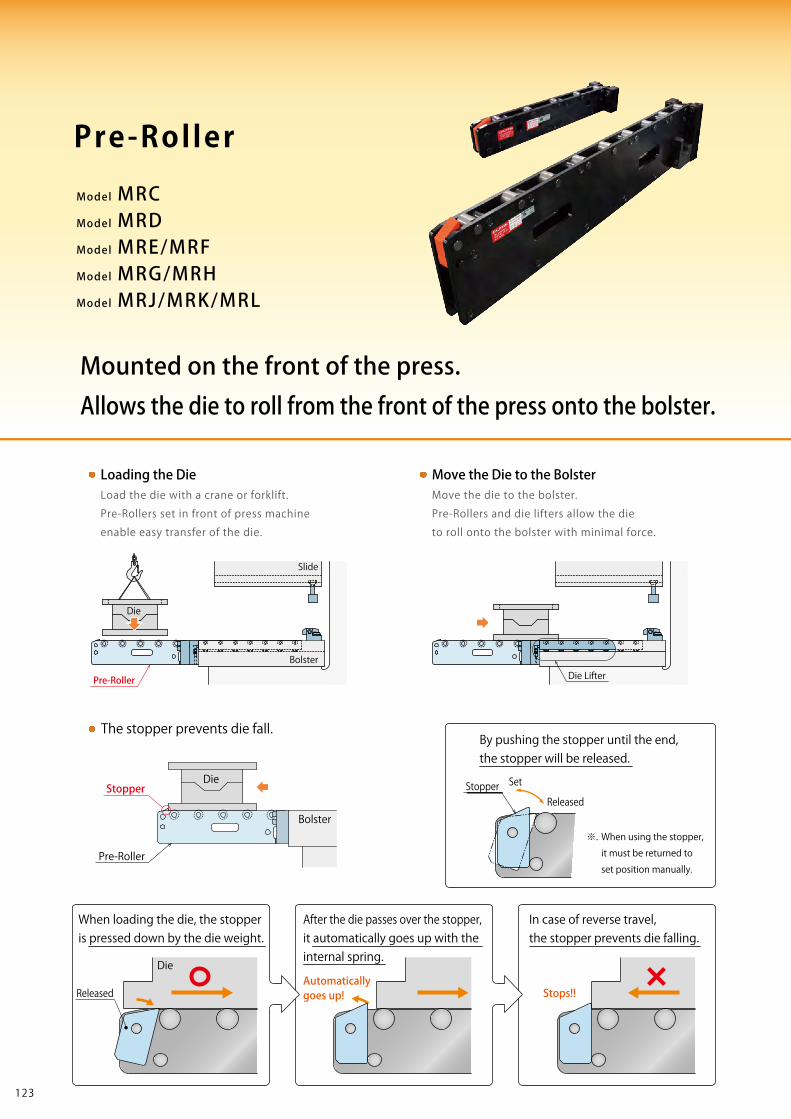
Mounted on the front of the press.Allows the die to roll from the front of the press onto the bolster.
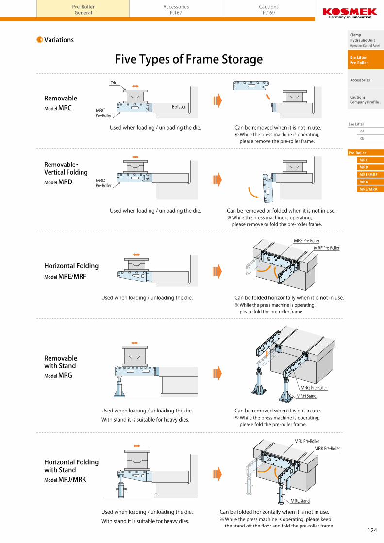
Five Types of Frame StoragePre-Roller
Variations
RemovableModel MRC
Removable・Vertical FoldingModel MRD
Horizontal Folding
Used when loading / unloading the die.
Model MRE/MRF
Removablewith StandModel MRG
Horizontal Foldingwith Stand
Used when loading / unloading the die.
With stand it is suitable for heavy dies.
Used when loading / unloading the die.
With stand it is suitable for heavy dies.
Can be removed when it is not in use.※ While the press machine is operating, please remove the pre-roller frame.
※ While the press machine is operating, please fold the pre-roller frame.
※ While the press machine is operating, please remove or fold the pre-roller frame.
※ While the press machine is operating, please fold the pre-roller frame.
※ While the press machine is operating, please keep the stand off the floor and fold the pre-roller frame.
Can be removed or folded when it is not in use.
Can be folded horizontally when it is not in use.
Can be removed when it is not in use.
Can be folded horizontally when it is not in use.
Model MRJ/MRK
MRE Pre-RollerMRF Pre-Roller
MRL Stand
MRJ Pre-RollerMRK Pre-Roller
MRH Stand
MRG Pre-Roller
Bolster
Stopper
Stops!!Automaticallygoes up!
Die
Die
Released
Pre-Roller
The stopper prevents die fall.
When loading the die, the stopper is pressed down by the die weight.
After the die passes over the stopper, it automatically goes up with the internal spring.
By pushing the stopper until the end, the stopper will be released.
In case of reverse travel, the stopper prevents die falling.
Pre-Roller
Bolster
Slide
Die Lifter
Move the Die to the BolsterLoading the DieLoad the die with a crane or forklift.
Pre-Rollers set in front of press machine
enable easy transfer of the die.
Move the die to the bolster.
Pre-Rollers and die lifters allow the die
to roll onto the bolster with minimal force.
Stopper Set
Released
※. When using the stopper,
it must be returned to
set position manually.
Die
Used when loading / unloading the die.
Used when loading / unloading the die.
Bolster
Die
MRCPre-Roller
MRDPre-Roller
124123
Die Lifter
RA
RB
Pre-Roller
MRC
MRD
MRE/MRF
MRG
MRJ/MRK
ClampHydraulic UnitOperation Control Panel
Die LifterPre-Roller
Accessories
CautionsCompany Profile
Pre-RollerGeneral
AccessoriesP.167
CautionsP.169
Model MRCModel MRDModel MRE/MRFModel MRG/MRHModel MRJ/MRK/MRL
Mounted on the front of the press.Allows the die to roll from the front of the press onto the bolster.
Five Types of Frame StoragePre-Roller
Variations
RemovableModel MRC
Removable・Vertical FoldingModel MRD
Horizontal Folding
Used when loading / unloading the die.
Model MRE/MRF
Removablewith StandModel MRG
Horizontal Foldingwith Stand
Used when loading / unloading the die.
With stand it is suitable for heavy dies.
Used when loading / unloading the die.
With stand it is suitable for heavy dies.
Can be removed when it is not in use.※ While the press machine is operating, please remove the pre-roller frame.
※ While the press machine is operating, please fold the pre-roller frame.
※ While the press machine is operating, please remove or fold the pre-roller frame.
※ While the press machine is operating, please fold the pre-roller frame.
※ While the press machine is operating, please keep the stand off the floor and fold the pre-roller frame.
Can be removed or folded when it is not in use.
Can be folded horizontally when it is not in use.
Can be removed when it is not in use.
Can be folded horizontally when it is not in use.
Model MRJ/MRK
MRE Pre-RollerMRF Pre-Roller
MRL Stand
MRJ Pre-RollerMRK Pre-Roller
MRH Stand
MRG Pre-Roller
Bolster
Stopper
Stops!!Automaticallygoes up!
Die
Die
Released
Pre-Roller
The stopper prevents die fall.
When loading the die, the stopper is pressed down by the die weight.
After the die passes over the stopper, it automatically goes up with the internal spring.
By pushing the stopper until the end, the stopper will be released.
In case of reverse travel, the stopper prevents die falling.
Pre-Roller
Bolster
Slide
Die Lifter
Move the Die to the BolsterLoading the DieLoad the die with a crane or forklift.
Pre-Rollers set in front of press machine
enable easy transfer of the die.
Move the die to the bolster.
Pre-Rollers and die lifters allow the die
to roll onto the bolster with minimal force.
Stopper Set
Released
※. When using the stopper,
it must be returned to
set position manually.
Die
Used when loading / unloading the die.
Used when loading / unloading the die.
Bolster
Die
MRCPre-Roller
MRDPre-Roller
124123
RA
RB
MRC
MRD
MRE/MRF
MRG
MRJ/MRK
Die Lifter
Pre-Roller
ClampHydraulic UnitOperation Control Panel
Die LifterPre-Roller
Accessories
CautionsCompany Profile
Pre-RollerGeneral P.123
Model No. IndicationSpecifications
MRC0750External Dimensions
MRC1190External Dimensions
MRC1500External Dimensions
MRC1900External Dimensions
AccessoriesP.167
CautionsP.169Pre-Roller Removable Type model MRC
Specifications
Compatible Mounting BlocksPre-Roller Model
MRC0750-□
MRC1190-□
MRC1500-□
MRC1900-□
Mounting Block Model
MRC0750-B
MRC1190-B
MRC1500-B
MRC1900-B
Mounting Block Weight (kg)
1.2
3.4
4.6
6.9
Model Weight (kg) Number of Rollers Die Travel to StopL (mm)
Note: 1. MRC Pre-Roller and MRC-B Mounting Block are sold separately. Order by type and number required.
Note: ※1. Maximum loading weight per pre-roller. at Roller A : When load extends to Roller A. at Point B : When load extends to distance L/4 from stopper.
Model No. Indication
1 2 3 4
MR C 119 0 - 630
4
3
Die Travel L・Mounting Block Type
Dimensions : Die Travel L (Distance that the die can be pulled out)
(Please refer to the specifications)
B : Mounting Block
1 Frame Storage Type
075 : Mounting Block Height 75 mm
119 : Mounting Block Height 119 mm
150 : Mounting Block Height 150 mm
190 : Mounting Block Height 190 mm
0 : Revision Number
Design No.
2 Mounting Block Height (Pre-Roller Height)
P.125
P.135
P.145
P.145
P.153
P.161
P.161
C
Mounting Block Height
Die Travel to Stop L
Mounting Block
Mounting Block
Die Travel to Stop L Roller A Point BDie Travel to Stop L
at Roller A at Point BMax. Loading Weight each (kg)※1
at Roller A at Point BMax. Loading Weight each (kg)※1
at Roller A at Point BMax. Loading Weight each (kg)※1
at Roller A at Point BMax. Loading Weight each (kg)※1
C : Removable Type
D : Removable・Vertical Folding Type
E : Horizontal Folding Type (Inside Arm)
F : Horizontal Folding Type (Outside Arm)
G : Removable Type (With Stand)
J : Horizontal Folding Type (With Stand) (Inside Arm)
K : Horizontal Folding Type (With Stand) (Outside Arm)
126125
RA
RB
MRC
MRD
MRE/MRF
MRG
MRJ/MRK
Die Lifter
Pre-Roller
ClampHydraulic UnitOperation Control Panel
Die LifterPre-Roller
Accessories
CautionsCompany Profile
Pre-RollerGeneral P.123
Model No. IndicationSpecifications
MRC0750External Dimensions
MRC1190External Dimensions
MRC1500External Dimensions
MRC1900External Dimensions
AccessoriesP.167
CautionsP.169Pre-Roller Removable Type model MRC
Specifications
Compatible Mounting BlocksPre-Roller Model
MRC0750-□
MRC1190-□
MRC1500-□
MRC1900-□
Mounting Block Model
MRC0750-B
MRC1190-B
MRC1500-B
MRC1900-B
Mounting Block Weight (kg)
1.2
3.4
4.6
6.9
Model Weight (kg) Number of Rollers Die Travel to StopL (mm)
Note: 1. MRC Pre-Roller and MRC-B Mounting Block are sold separately. Order by type and number required.
Note: ※1. Maximum loading weight per pre-roller. at Roller A : When load extends to Roller A. at Point B : When load extends to distance L/4 from stopper.
Model No. Indication
1 2 3 4
MR C 119 0 - 630
4
3
Die Travel L・Mounting Block Type
Dimensions : Die Travel L (Distance that the die can be pulled out)
(Please refer to the specifications)
B : Mounting Block
1 Frame Storage Type
075 : Mounting Block Height 75 mm
119 : Mounting Block Height 119 mm
150 : Mounting Block Height 150 mm
190 : Mounting Block Height 190 mm
0 : Revision Number
Design No.
2 Mounting Block Height (Pre-Roller Height)
P.125
P.135
P.145
P.145
P.153
P.161
P.161
C
Mounting Block Height
Die Travel to Stop L
Mounting Block
Mounting Block
Die Travel to Stop L Roller A Point BDie Travel to Stop L
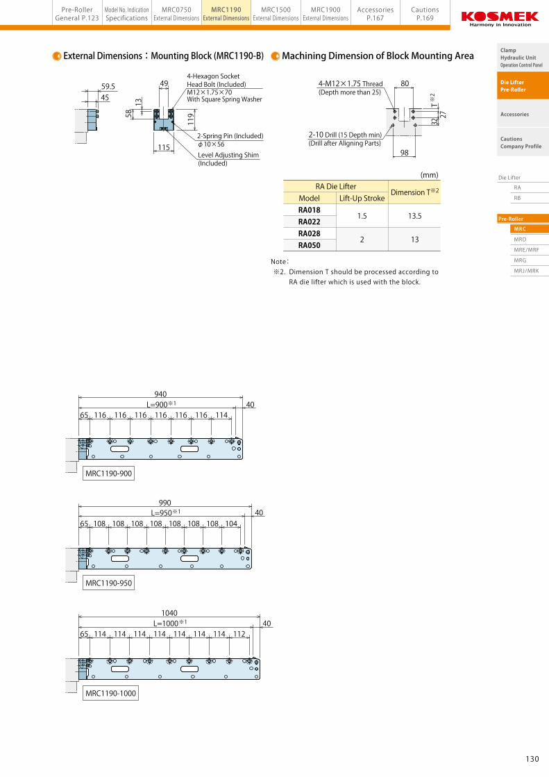
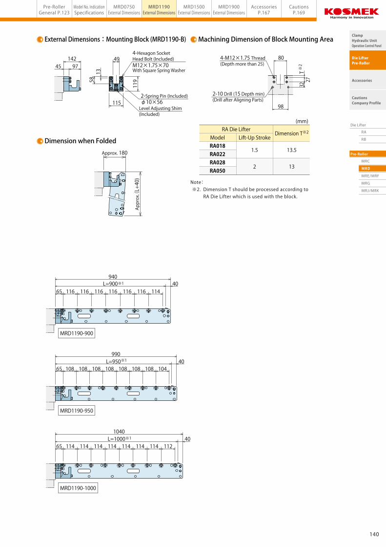
2-10 Drill (15 Depth min) (Drill after Aligning Parts)
4-M12×1.75 Thread (Depth more than 25)
132131
RA
RB
MRC
MRD
MRE/MRF
MRG
MRJ/MRK
Die Lifter
Pre-Roller
ClampHydraulic UnitOperation Control Panel
Die LifterPre-Roller
Accessories
CautionsCompany Profile
Model No. IndicationSpecifications
MRC0750External Dimensions
MRC1190External Dimensions
MRC1500External Dimensions
MRC1900External Dimensions
Pre-RollerGeneral P.123
AccessoriesP.167
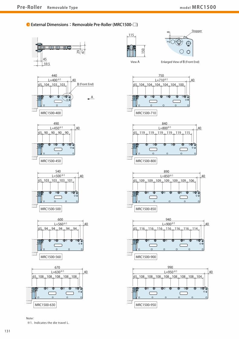
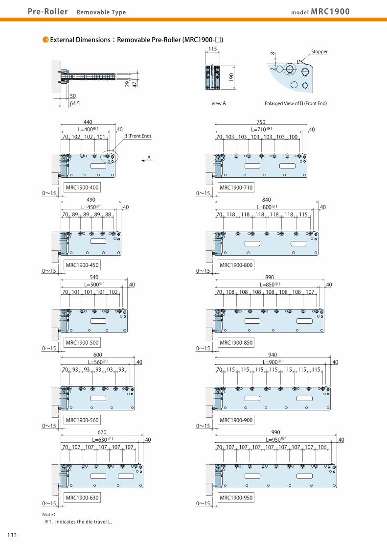
CautionsP.169model MRC1900Pre-Roller Removable Type
External Dimensions:Mounting Block (MRC1900-B) Machining Dimension of Block Mounting Area
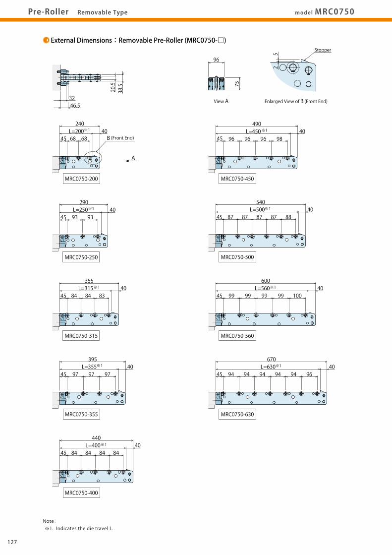
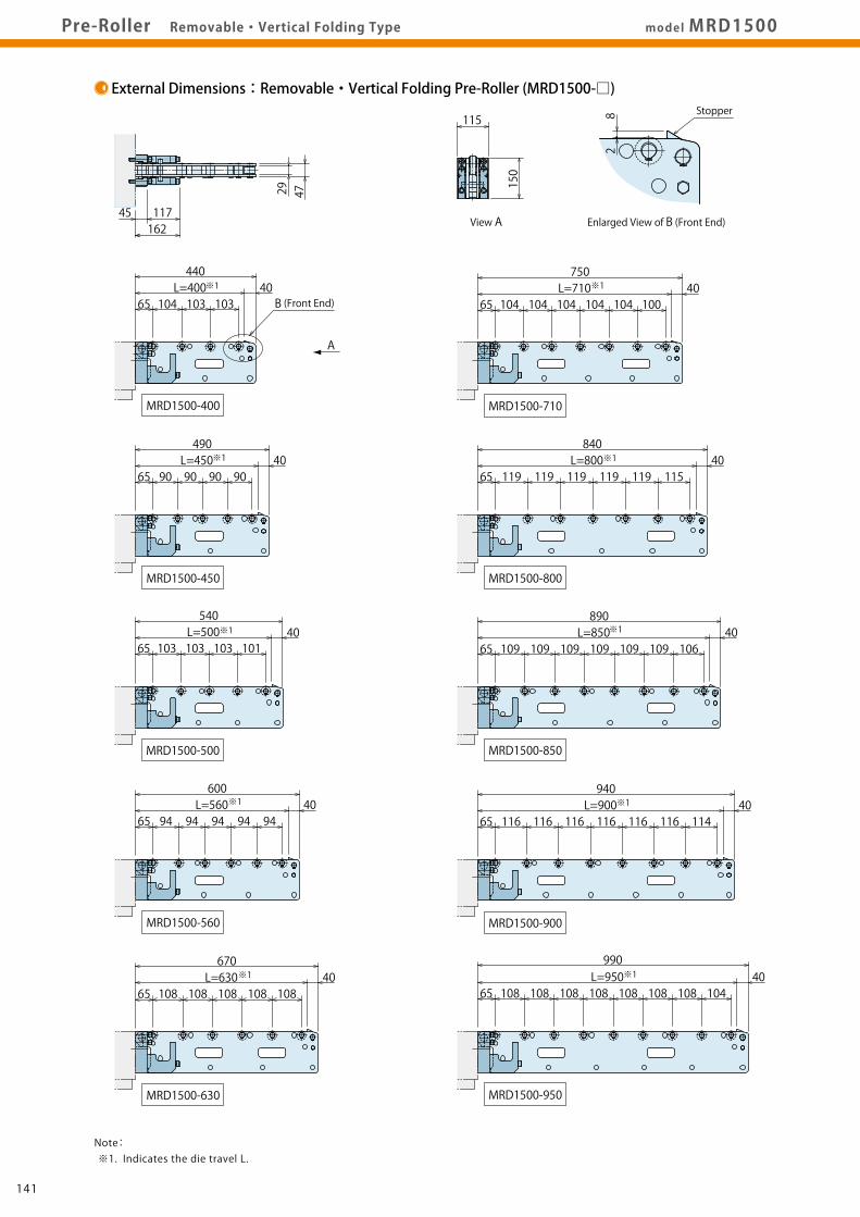
Note: ※1. Indicates the die travel L.
Notes: ※2. Dimension T should be processed according to RA die lifter which is used with the block. ※3. Use a push bolt when the bolster thickness is 160mm or less.
2-10 Drill (15 Depth min) (Drill after Aligning Parts)
6-Hexagon Socket Head Bolt (Included)M12×1.75×75With Square Spring Washer
49
115
190
58
Level Adjusting Shim (Included)
2-Spring Pin (Included)φ10×63Push Bolt
(M16×2)
12
134133
RA
RB
MRC
MRD
MRE/MRF
MRG
MRJ/MRK
Die Lifter
Pre-Roller
ClampHydraulic UnitOperation Control Panel
Die LifterPre-Roller
Accessories
CautionsCompany Profile
Model No. IndicationSpecifications
MRC0750External Dimensions
MRC1190External Dimensions
MRC1500External Dimensions
MRC1900External Dimensions
Pre-RollerGeneral P.123
AccessoriesP.167
CautionsP.169model MRC1900Pre-Roller Removable Type
External Dimensions:Mounting Block (MRC1900-B) Machining Dimension of Block Mounting Area
Note: ※1. Indicates the die travel L.
Notes: ※2. Dimension T should be processed according to RA die lifter which is used with the block. ※3. Use a push bolt when the bolster thickness is 160mm or less.
Note: ※1. Maximum loading weight per pre-roller. at Roller A : When load extends to Roller A. at Point B : When load extends to distance L/4 from stopper.
L / 4
at Roller A at Point BMax. Loading Weight each (kg)※1
at Roller A at Point BMax. Loading Weight each (kg)※1
at Roller A at Point BMax. Loading Weight each (kg)※1
at Roller A at Point BMax. Loading Weight each (kg)※1
4
1 Frame Storage Type
D
Die Travel to Stop L
Mounting Block
Removable・Vertical FoldingPre-Roller
C : Removable Type
D : Removable・Vertical Folding Type
E : Horizontal Folding Type (Inside Arm)
F : Horizontal Folding Type (Outside Arm)
G : Removable Type (With Stand)
J : Horizontal Folding Type (With Stand) (Inside Arm)
K : Horizontal Folding Type (With Stand) (Outside Arm)
Die Travel L・Mounting Block Type
Dimensions : Die Travel L (Distance that the die can be pulled out)
(Please refer to the specifications)
B : Mounting Block
2
Mounting Block Height
Mounting Block
075 : Mounting Block Height 75 mm
119 : Mounting Block Height 119 mm
150 : Mounting Block Height 150 mm
190 : Mounting Block Height 190 mm
Mounting Block Height (Pre-Roller Height)
136135
RA
RB
MRC
MRD
MRE/MRF
MRG
MRJ/MRK
Die Lifter
Pre-Roller
ClampHydraulic UnitOperation Control Panel
Die LifterPre-Roller
Accessories
CautionsCompany Profile
Model No. IndicationSpecifications
MRD0750External Dimensions
MRD1190External Dimensions
MRD1500External Dimensions
MRD1900External Dimensions
Pre-RollerGeneral P.123
AccessoriesP.167
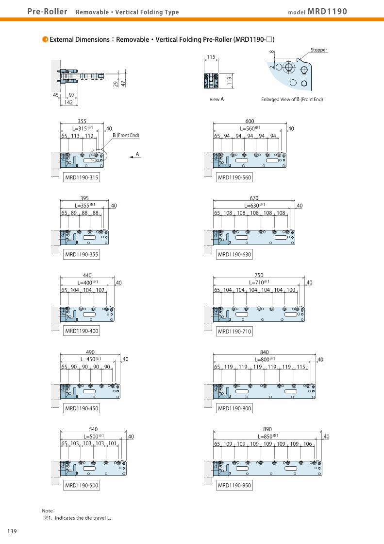
CautionsP.169Pre-Roller Removable・Vertical Folding Type model MRD
Specifications
Compatible Mounting BlocksPre-Roller Model No.
MRD0750-□
MRD1190-□
MRD1500-□
MRD1900-□
Mounting Block Model No.
MRD0750-B
MRD1190-B
MRD1500-B
MRD1900-B
Mounting Block Weight (kg)
1.7
5.0
6.0
8.3
Model No. Weight (kg) Number of Rollers Die Travel to StopL (mm)
Note: 1. MRD Pre-Roller and MRD-B Mounting Block are sold separately. Order by type and number required.
Note: ※1. Maximum loading weight per pre-roller. at Roller A : When load extends to Roller A. at Point B : When load extends to distance L/4 from stopper.
L / 4
at Roller A at Point BMax. Loading Weight each (kg)※1
at Roller A at Point BMax. Loading Weight each (kg)※1
at Roller A at Point BMax. Loading Weight each (kg)※1
at Roller A at Point BMax. Loading Weight each (kg)※1
4
1 Frame Storage Type
D
Die Travel to Stop L
Mounting Block
Removable・Vertical FoldingPre-Roller
C : Removable Type
D : Removable・Vertical Folding Type
E : Horizontal Folding Type (Inside Arm)
F : Horizontal Folding Type (Outside Arm)
G : Removable Type (With Stand)
J : Horizontal Folding Type (With Stand) (Inside Arm)
K : Horizontal Folding Type (With Stand) (Outside Arm)
Die Travel L・Mounting Block Type
Dimensions : Die Travel L (Distance that the die can be pulled out)
(Please refer to the specifications)
B : Mounting Block
2
Mounting Block Height
Mounting Block
075 : Mounting Block Height 75 mm
119 : Mounting Block Height 119 mm
150 : Mounting Block Height 150 mm
190 : Mounting Block Height 190 mm
Mounting Block Height (Pre-Roller Height)
136135
RA
RB
MRC
MRD
MRE/MRF
MRG
MRJ/MRK
Die Lifter
Pre-Roller
ClampHydraulic UnitOperation Control Panel
Die LifterPre-Roller
Accessories
CautionsCompany Profile
Model No. IndicationSpecifications
MRD0750External Dimensions
MRD1190External Dimensions
MRD1500External Dimensions
MRD1900External Dimensions
Pre-RollerGeneral P.123
AccessoriesP.167
CautionsP.169model MRD0750Pre-Roller Removable・Vertical Folding Type
External Dimensions:Mounting Block (MRD0750-B) Machining Dimension of Block Mounting Area
98 2-10 Drill (15 Depth min) (Drill after Aligning Parts)
86(M16×2)
4040
8420
T
※3
※3
※249
115
190
58
115
190
Level Adjusting Shim (Included)
2-Spring Pin (Included)φ10×63
0~15
0~15
0~15
0~15 0~15 0~15
0~15
0~15
0~15
0~15
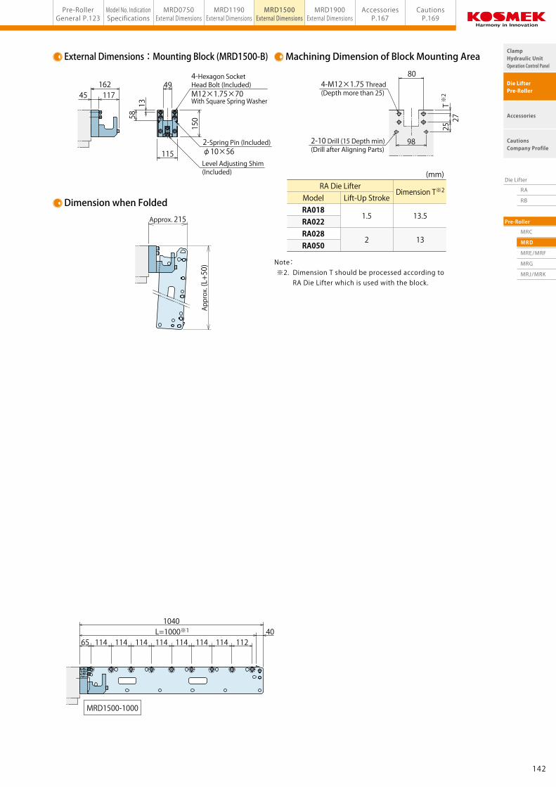
Notes: ※2. Dimension T should be processed according to RA Die Lifter which is used with the block. ※3. Use a push bolt when the bolster thickness is 160mm or less.
12
(mm)
View A Enlarged View of B (Front End)
Approx. 260
Approx. (L+85)
6-M12×1.75 Thread (Depth more than 25)
Bolster Thickness
6-Hexagon Socket Head Bolt (Included)M12×1.75×75With Square Spring Washer
144143
RA
RB
MRC
MRD
MRE/MRF
MRG
MRJ/MRK
Die Lifter
Pre-Roller
ClampHydraulic UnitOperation Control Panel
Die LifterPre-Roller
Accessories
CautionsCompany Profile
Model No. IndicationSpecifications
MRD0750External Dimensions
MRD1190External Dimensions
MRD1500External Dimensions
MRD1900External Dimensions
Pre-RollerGeneral P.123
AccessoriesP.167
CautionsP.169Pre-Roller Removable・Vertical Folding Type model MRD1900
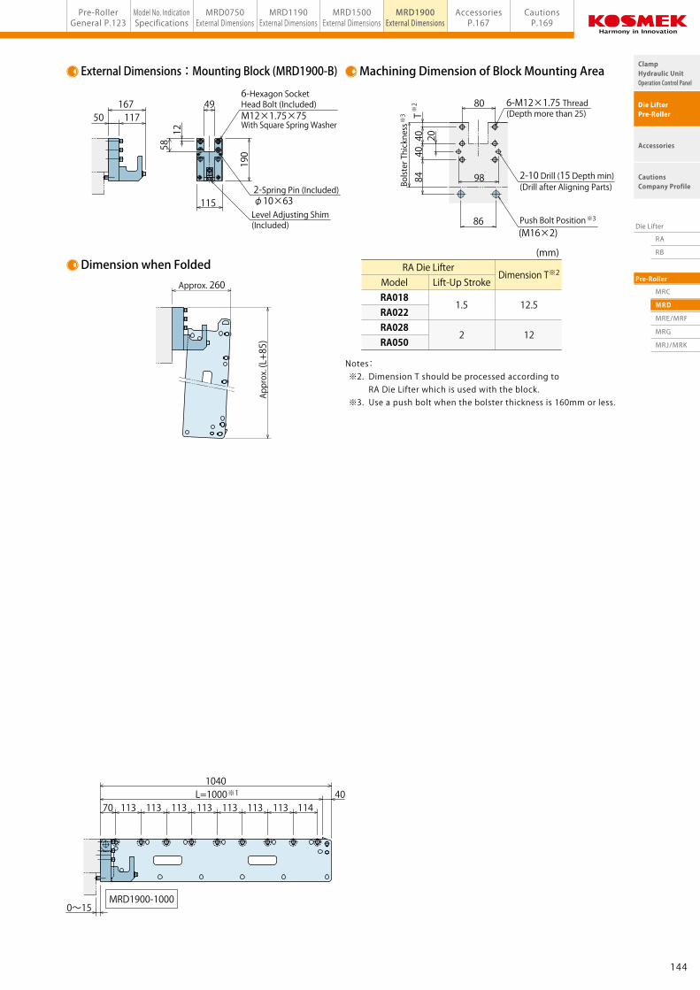
External Dimensions:Mounting Block (MRD1900-B) Machining Dimension of Block Mounting Area
98 2-10 Drill (15 Depth min) (Drill after Aligning Parts)
86(M16×2)
4040
8420
T
※3
※3
※249
115
190
58
115
190
Level Adjusting Shim (Included)
2-Spring Pin (Included)φ10×63
0~15
0~15
0~15
0~15 0~15 0~15
0~15
0~15
0~15
0~15
Notes: ※2. Dimension T should be processed according to RA Die Lifter which is used with the block. ※3. Use a push bolt when the bolster thickness is 160mm or less.
12
(mm)
View A Enlarged View of B (Front End)
Approx. 260
Approx. (L+85)
6-M12×1.75 Thread (Depth more than 25)
Bolster Thickness
6-Hexagon Socket Head Bolt (Included)M12×1.75×75With Square Spring Washer
144143
RA
RB
MRC
MRD
MRE/MRF
MRG
MRJ/MRK
Die Lifter
Pre-Roller
ClampHydraulic UnitOperation Control Panel
Die LifterPre-Roller
Accessories
CautionsCompany Profile
Pre-RollerGeneral P.123
Model No. IndicationSpecifications
MRE/MRF1190External Dimensions
MRE/MRF1900External Dimensions
MRE/MRF2950External Dimensions
AccessoriesP.167
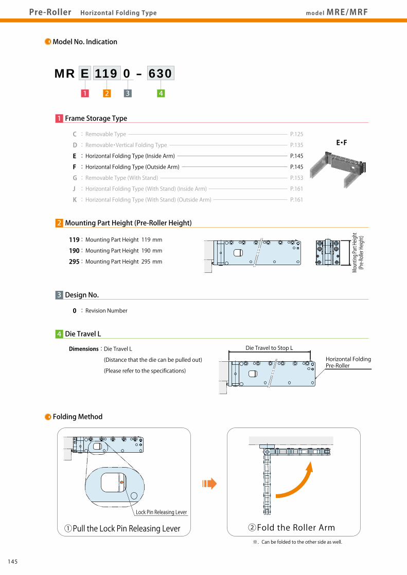
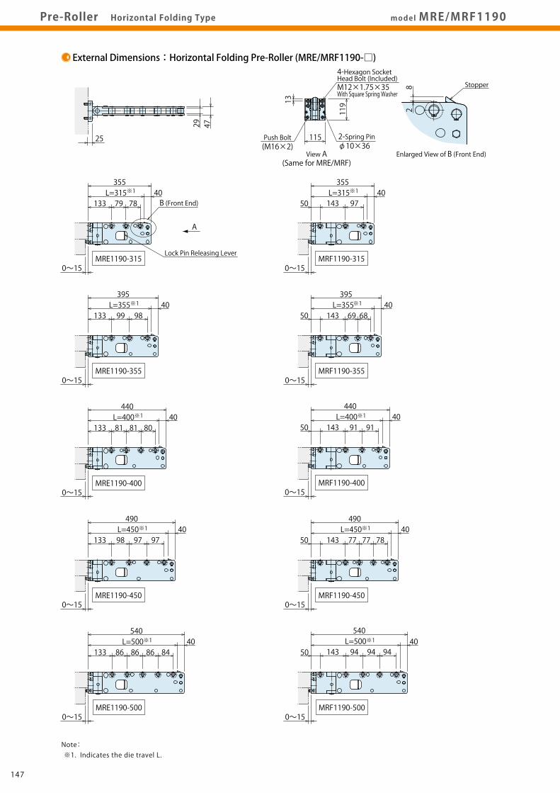
CautionsP.169model MRE/MRFPre-Roller Horizontal Folding Type
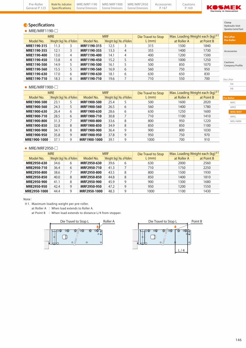
Specifications
Folding Method
Model No. Weight (kg) No. of RollersMRE MRF Die Travel to Stop
Model No. Weight (kg) No. of RollersMRF1190-315MRF1190-355MRF1190-400MRF1190-450MRF1190-500MRF1190-560MRF1190-630MRF1190-710
12.513.314.115.216.116.918.119.6
34455667
315355400450500560630710
1500140012001000850750650550
Die Travel to Stop L Point BDie Travel to Stop L
Model No. Weight (kg) No. of RollersMRE MRF Die Travel to Stop
L (mm)MRE1900-500MRE1900-560MRE1900-630MRE1900-710MRE1900-800MRE1900-850MRE1900-900MRE1900-950MRE1900-1000
23.124.326.428.531.332.834.135.837.1
556678899
Model No. Weight (kg) No. of RollersMRF1900-500MRF1900-560MRF1900-630MRF1900-710MRF1900-800MRF1900-850MRF1900-900MRF1900-950MRF1900-1000
25.426.528.630.833.634.936.437.839.1
566788999
5005606307108008509009501000
1600140012501100950850800750700
Model No. Weight (kg) No. of RollersMRE MRF Die Travel to Stop
L (mm)MRE2950-630MRE2950-710MRE2950-800MRE2950-850MRE2950-900MRE2950-950MRE2950-1000
34.636.438.640.041.142.444.4
6678899
Model No. Weight (kg) No. of RollersMRF2950-630MRF2950-710MRF2950-800MRF2950-850MRF2950-900MRF2950-950MRF2950-1000
39.641.343.544.845.947.248.3
6788999
6307108008509009501000
2000175015001400130012001100
18401730150012501070950830700
2020178016001410122011001030970910
2560225019301810168015501430
MRE/MRF1190-□
MRE/MRF1900-□
MRE/MRF2950-□
Note: ※1. Maximum loading weight per pre-roller. at Roller A : When load extends to Roller A. at Point B : When load extends to distance L/4 from stopper.
L / 4
at Roller A at Point BMax. Loading Weight each (kg)※1
at Roller A at Point BMax. Loading Weight each (kg)※1
at Roller A at Point BMax. Loading Weight each (kg)※1
4
3
Die Travel L
Dimensions : Die Travel L
(Distance that the die can be pulled out)
(Please refer to the specifications)
1 Frame Storage Type
C : Removable Type
D : Removable・Vertical Folding Type
E : Horizontal Folding Type (Inside Arm)
F : Horizontal Folding Type (Outside Arm)
G : Removable Type (With Stand)
J : Horizontal Folding Type (With Stand) (Inside Arm)
K : Horizontal Folding Type (With Stand) (Outside Arm)
119 : Mounting Part Height 119 mm
190 : Mounting Part Height 190 mm
295 : Mounting Part Height 295 mm
0 : Revision Number
Design No.
2 Mounting Part Height (Pre-Roller Height)
E・F
Mounting Part Height
(Pre-Roller Height)
Die Travel to Stop L
①Pull the Lock Pin Releasing Lever ②Fold the Roller Arm
Lock Pin Releasing Lever
Horizontal FoldingPre-Roller
※. Can be folded to the other side as well.
146145
RA
RB
MRC
MRD
MRE/MRF
MRG
MRJ/MRK
Die Lifter
Pre-Roller
ClampHydraulic UnitOperation Control Panel
Die LifterPre-Roller
Accessories
CautionsCompany Profile
Pre-RollerGeneral P.123
Model No. IndicationSpecifications
MRE/MRF1190External Dimensions
MRE/MRF1900External Dimensions
MRE/MRF2950External Dimensions
AccessoriesP.167
CautionsP.169model MRE/MRFPre-Roller Horizontal Folding Type
Specifications
Folding Method
Model No. Weight (kg) No. of RollersMRE MRF Die Travel to Stop
Model No. Weight (kg) No. of RollersMRF1190-315MRF1190-355MRF1190-400MRF1190-450MRF1190-500MRF1190-560MRF1190-630MRF1190-710
12.513.314.115.216.116.918.119.6
34455667
315355400450500560630710
1500140012001000850750650550
Die Travel to Stop L Point BDie Travel to Stop L
Model No. Weight (kg) No. of RollersMRE MRF Die Travel to Stop
L (mm)MRE1900-500MRE1900-560MRE1900-630MRE1900-710MRE1900-800MRE1900-850MRE1900-900MRE1900-950MRE1900-1000
23.124.326.428.531.332.834.135.837.1
556678899
Model No. Weight (kg) No. of RollersMRF1900-500MRF1900-560MRF1900-630MRF1900-710MRF1900-800MRF1900-850MRF1900-900MRF1900-950MRF1900-1000
25.426.528.630.833.634.936.437.839.1
566788999
5005606307108008509009501000
1600140012501100950850800750700
Model No. Weight (kg) No. of RollersMRE MRF Die Travel to Stop
L (mm)MRE2950-630MRE2950-710MRE2950-800MRE2950-850MRE2950-900MRE2950-950MRE2950-1000
34.636.438.640.041.142.444.4
6678899
Model No. Weight (kg) No. of RollersMRF2950-630MRF2950-710MRF2950-800MRF2950-850MRF2950-900MRF2950-950MRF2950-1000
39.641.343.544.845.947.248.3
6788999
6307108008509009501000
2000175015001400130012001100
18401730150012501070950830700
2020178016001410122011001030970910
2560225019301810168015501430
MRE/MRF1190-□
MRE/MRF1900-□
MRE/MRF2950-□
Note: ※1. Maximum loading weight per pre-roller. at Roller A : When load extends to Roller A. at Point B : When load extends to distance L/4 from stopper.
L / 4
at Roller A at Point BMax. Loading Weight each (kg)※1
at Roller A at Point BMax. Loading Weight each (kg)※1
at Roller A at Point BMax. Loading Weight each (kg)※1
4
3
Die Travel L
Dimensions : Die Travel L
(Distance that the die can be pulled out)
(Please refer to the specifications)
1 Frame Storage Type
C : Removable Type
D : Removable・Vertical Folding Type
E : Horizontal Folding Type (Inside Arm)
F : Horizontal Folding Type (Outside Arm)
G : Removable Type (With Stand)
J : Horizontal Folding Type (With Stand) (Inside Arm)
K : Horizontal Folding Type (With Stand) (Outside Arm)
119 : Mounting Part Height 119 mm
190 : Mounting Part Height 190 mm
295 : Mounting Part Height 295 mm
0 : Revision Number
Design No.
2 Mounting Part Height (Pre-Roller Height)
E・F
Mounting Part Height
(Pre-Roller Height)
Die Travel to Stop L
①Pull the Lock Pin Releasing Lever ②Fold the Roller Arm
Lock Pin Releasing Lever
Horizontal FoldingPre-Roller
※. Can be folded to the other side as well.
146145
RA
RB
MRC
MRD
MRE/MRF
MRG
MRJ/MRK
Die Lifter
Pre-Roller
ClampHydraulic UnitOperation Control Panel
Die LifterPre-Roller
Accessories
CautionsCompany Profile
Model No. IndicationSpecifications
MRE/MRF1190External Dimensions
MRE/MRF1900External Dimensions
MRE/MRF2950External Dimensions
Pre-RollerGeneral P.123
AccessoriesP.167
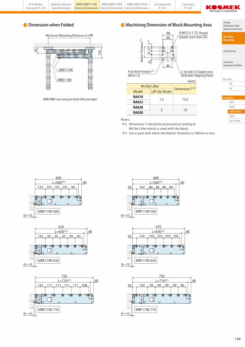
CautionsP.169model MRE/MRF1190Pre-Roller Horizontal Folding Type
Machining Dimension of Block Mounting AreaDimension when Folded
Enlarged View of B (Front End)View A(Same for MRE/MRF)
MRE/MRF can swing to both left and right.
ModelRA018RA022RA028RA050
RA Die LifterDimension T※2
13.5
13
Lift-Up Stroke
1.5
2
A
MRE1190-315
MRE1190-355
MRE1190-450
MRE1190-500
MRE1190-400
MRF1190-315
MRF1190-355
MRF1190-450
MRF1190-500
MRF1190-400
L=400440
143 91 91133L=400440
8081 81
L=355395
143 69 68133L=355395
99 98
L=315355
143 97133L=315355
79 78
L=450490
143 7877 77133L=450490
9798 97
L=500540
143 9494 94133L=500540
848686 86
0~15
0~15
0~15
0~15
0~15 0~15 0~15
0~15
0~15 0~15
0~15
0~15
0~15
0~15
0~15
0~15
25
40
40
40
40
40 4050
50
50
50
50
40
40
40
40B (Front End)
4729
Lock Pin Releasing Lever
※1
※1
※1
※1
※1
※1
※1
※1
※1
※1
MRE1190-560
MRE1190-630
MRE1190-710
MRF1190-560
MRF1190-630
MRF1190-710
L=710750
143 96999999 99133L=710750
108111111111 111
L=630670
143 103103103 103133L=630670
92959595 95
L=560600
143 848686 86133L=560600
99101101 101
50
50
5040
40
40 40
40
40※1
※1
※1
※1
※1
※1
Stopper
28
Push Bolt 2-Spring Pinφ10×36(M16×2)
115
119
Push Bolt Position
T27
32
(M16×2)
Bolster Thickness
33
※3
※3
※2
4-M12×1.75 Thread (Depth more than 25)80
86
98
MRE1190
MRF1190
14282
Minimum Mounting Distance=L+40
Notes: ※2. Dimension T should be processed according to RA Die Lifter which is used with the block. ※3. Use a push bolt when the bolster thickness is 100mm or less.
13
(mm)
4-Hexagon Socket Head Bolt (Included)M12×1.75×35With Square Spring Washer
2-10 Drill (15 Depth min) (Drill after Aligning Parts)
148147
RA
RB
MRC
MRD
MRE/MRF
MRG
MRJ/MRK
Die Lifter
Pre-Roller
ClampHydraulic UnitOperation Control Panel
Die LifterPre-Roller
Accessories
CautionsCompany Profile
Model No. IndicationSpecifications
MRE/MRF1190External Dimensions
MRE/MRF1900External Dimensions
MRE/MRF2950External Dimensions
Pre-RollerGeneral P.123
AccessoriesP.167
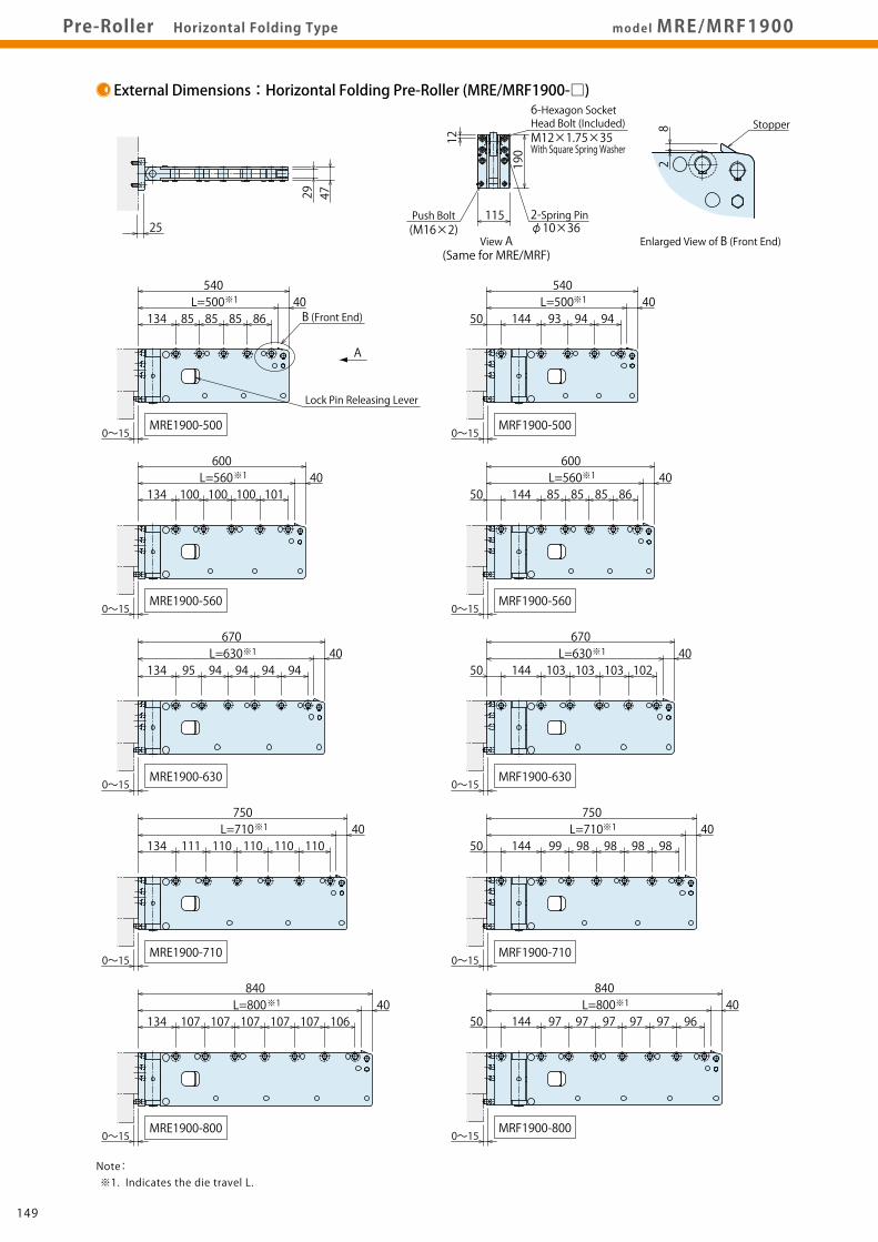
CautionsP.169Pre-Roller Horizontal Folding Type model MRE/MRF1900
Machining Dimension of Block Mounting AreaDimension when Folded
Enlarged View of B (Front End)View A(Same for MRE/MRF)
Push Bolt 2-Spring Pinφ10×36
115
190
(M16×2)
80
98
4084
4020
T
86Push Bolt Position(M16×2)
※3
※3 ※2Stopper
28
MRE/MRF can swing to both left and right.
MRE1900
MRF1900
14282
Minimum Mounting Distance=L+40
A
0~15
L=50086858585134
540
600L=560
101100100100134
750L=710
110110110110111134
670L=630
9494949495134
4729
MRE1900-500
MRE1900-560
MRE1900-630
MRE1900-710
L=500144 93 94 94
540
L=560144
600
85 85 85 86
L=630144
670
102103103103
L=710144
750
99 98 98 98 98
L=800134
840
107 107 107 107 107 106L=800
144
840
97 97 97 97 97 96
MRF1900-500
MRF1900-560
MRF1900-630
MRF1900-710
MRE1900-800 MRF1900-800
B (Front End)
25
40
40
40
40
40 40
40
40
40
4050
50
50
50
50
Lock Pin Releasing Lever
0~15
0~15 0~15
0~15 0~15
0~15 0~15
0~15 0~15
※1
※1
※1
※1
※1
※1
※1
※1
※1
※1
ModelRA018RA022RA028RA050
RA Die LifterDimension T※2
12.5
12
Lift-Up Stroke
1.5
2
MRE1900-850
MRE1900-900
MRE1900-950
MRE1900-1000
MRF1900-850
MRF1900-900
MRF1900-950
MRF1900-1000
L=850134
890
99 99 99 99 99 99 97L=850
144
890
106 105 105 105105 105
L=900134
940
106106106 106 106 106 105L=900
144
940
9797 97 97 97 97 99
L=950134
990
999999 99 99 99 99 98L=950
144
990
104 104 104 104 104 104 107
L=1000134
1040
105105105 105 105 105 105 106L=1000
144
1040
112 112 112 112 112 112 109
40
40
40
40 40
40
40
40
50
50
50
50
0~15 0~15
0~15 0~15
0~15 0~15
0~15 0~15
※1 ※1
※1 ※1
※1 ※1
※1 ※1
Notes: ※2. Dimension T should be processed according to RA Die Lifter which is used with the block. ※3. Use a push bolt when the bolster thickness is 160mm or less.
12
(mm)
6-Hexagon Socket Head Bolt (Included)M12×1.75×35 With Square Spring Washer
6-M12×1.75 Thread (Depth more than 25)
2-10 Drill (15 Depth min) (Drill after Aligning Parts)
Bolster Thickness
150149
RA
RB
MRC
MRD
MRE/MRF
MRG
MRJ/MRK
Die Lifter
Pre-Roller
ClampHydraulic UnitOperation Control Panel
Die LifterPre-Roller
Accessories
CautionsCompany Profile
Model No. IndicationSpecifications
MRE/MRF1190External Dimensions
MRE/MRF1900External Dimensions
MRE/MRF2950External Dimensions
Pre-RollerGeneral P.123
AccessoriesP.167
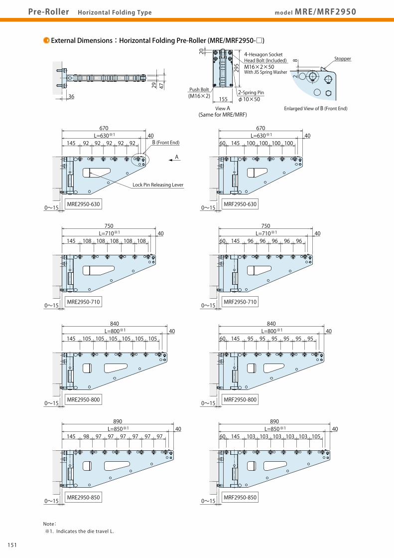
CautionsP.169model MRE/MRF2950Pre-Roller Horizontal Folding Type
Machining Dimension of Block Mounting AreaDimension when FoldedExternal Dimensions:Horizontal Folding Pre-Roller (MRE/MRF2950-□)
Enlarged View of B (Front End)View A(Same for MRE/MRF)
MRE/MRF can swing to both left and right.
ModelRA018RA022RA028RA050
RA Die LifterDimension T※2
20.5
20
Lift-Up Stroke
1.5
2
A
670L=630
145 92 92 92 92 92
670L=630
60 145 100 100 100 100
MRE2950-630
750L=710
145 108108108108108
750L=710
60 145 96 96 9696 96
MRE2950-710 MRF2950-710
105 105 105 105 105145
840L=800
105L=800
60 9595959595
840
145 95
MRE2950-800 MRF2950-800
0~15
890L=850
145 98 97 97 97 97 97 97L=850
60
890
145 103 103 103 103 103 105
MRE2950-850 MRF2950-850
MRF2950-630
4729
B (Front End)
36
40
40
40
40 40
40
40
40
Lock Pin Releasing Lever
0~15
0~15 0~15
0~15 0~15
0~15 0~15
※1
※1
※1
※1
※1
※1
※1
※1
940L=900
145 104 104 104 104 104 104 106
940L=900
60 145 96 96 96 96 96 96 94
MRE2950-900 MRF2950-900
990L=950
145 98 98 98 98 98 98 98 94
990L=950
60 145 103 103 103 103 103 103 102
MRE2950-950 MRF2950-950
1040L=1000
145 104 104 104 104 104 104 104 102
1040L=1000
60 110110110110110110110145
MRE2950-1000 MRF2950-1000
40
40
40 40
40
40
0~15 0~15
0~15 0~15
0~15 0~15
※1 ※1
※1 ※1
※1 ※1
Stopper
28
Push Bolt 2-Spring Pin
295
155 φ10×50(M16×2)
4-M16×2 Thread (Depth more than 35)T
5025
185
126(M16×2)
115
138
Push Bolt Position※3
※2
MRF2950
MRE2950
15393
Minimum Mounting Distance=L+50
Notes: ※2. Dimension T should be processed according to RA Die Lifter which is used with the block. ※3. Use a push bolt when the bolster thickness is 245mm or less.
20
(mm)
4-Hexagon Socket Head Bolt (Included)M16×2×50 With JIS Spring Washer
Note: ※1. Indicates the die travel L.
2-10 Drill (15 Depth min) (Drill after Aligning Parts)
Bolster Thickness※3
152151
RA
RB
MRC
MRD
MRE/MRF
MRG
MRJ/MRK
Die Lifter
Pre-Roller
ClampHydraulic UnitOperation Control Panel
Die LifterPre-Roller
Accessories
CautionsCompany Profile
Model No. IndicationSpecifications
MRE/MRF1190External Dimensions
MRE/MRF1900External Dimensions
MRE/MRF2950External Dimensions
Pre-RollerGeneral P.123
AccessoriesP.167
CautionsP.169model MRE/MRF2950Pre-Roller Horizontal Folding Type
Machining Dimension of Block Mounting AreaDimension when FoldedExternal Dimensions:Horizontal Folding Pre-Roller (MRE/MRF2950-□)
Enlarged View of B (Front End)View A(Same for MRE/MRF)
MRE/MRF can swing to both left and right.
ModelRA018RA022RA028RA050
RA Die LifterDimension T※2
20.5
20
Lift-Up Stroke
1.5
2
A
670L=630
145 92 92 92 92 92
670L=630
60 145 100 100 100 100
MRE2950-630
750L=710
145 108108108108108
750L=710
60 145 96 96 9696 96
MRE2950-710 MRF2950-710
105 105 105 105 105145
840L=800
105L=800
60 9595959595
840
145 95
MRE2950-800 MRF2950-800
0~15
890L=850
145 98 97 97 97 97 97 97L=850
60
890
145 103 103 103 103 103 105
MRE2950-850 MRF2950-850
MRF2950-630
4729
B (Front End)
36
40
40
40
40 40
40
40
40
Lock Pin Releasing Lever
0~15
0~15 0~15
0~15 0~15
0~15 0~15
※1
※1
※1
※1
※1
※1
※1
※1
940L=900
145 104 104 104 104 104 104 106
940L=900
60 145 96 96 96 96 96 96 94
MRE2950-900 MRF2950-900
990L=950
145 98 98 98 98 98 98 98 94
990L=950
60 145 103 103 103 103 103 103 102
MRE2950-950 MRF2950-950
1040L=1000
145 104 104 104 104 104 104 104 102
1040L=1000
60 110110110110110110110145
MRE2950-1000 MRF2950-1000
40
40
40 40
40
40
0~15 0~15
0~15 0~15
0~15 0~15
※1 ※1
※1 ※1
※1 ※1
Stopper
28
Push Bolt 2-Spring Pin
295
155 φ10×50(M16×2)
4-M16×2 Thread (Depth more than 35)T
5025
185
126(M16×2)
115
138
Push Bolt Position※3
※2
MRF2950
MRE2950
15393
Minimum Mounting Distance=L+50
Notes: ※2. Dimension T should be processed according to RA Die Lifter which is used with the block. ※3. Use a push bolt when the bolster thickness is 245mm or less.
20
(mm)
4-Hexagon Socket Head Bolt (Included)M16×2×50 With JIS Spring Washer
Note: ※1. Indicates the die travel L.
2-10 Drill (15 Depth min) (Drill after Aligning Parts)
Bolster Thickness※3
152151
RA
RB
MRC
MRD
MRE/MRF
MRG
MRJ/MRK
Die Lifter
Pre-Roller
ClampHydraulic UnitOperation Control Panel
Die LifterPre-Roller
Accessories
CautionsCompany Profile
Model No. IndicationSpecifications
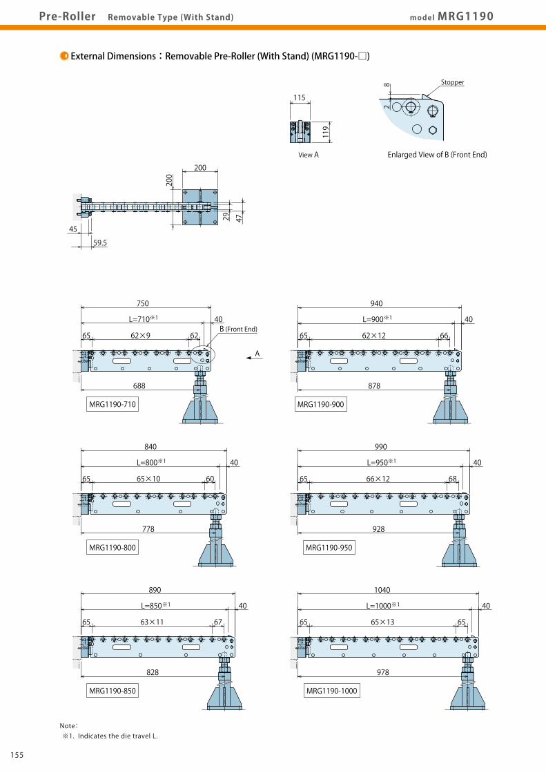
MRG1190External Dimensions
MRG1900External Dimensions
MRH StandExternal Dimensions
Pre-RollerGeneral P.123
AccessoriesP.167
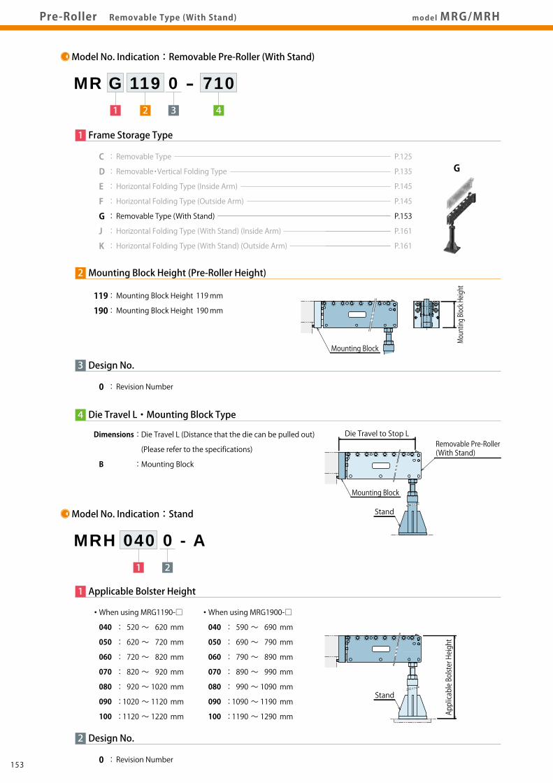
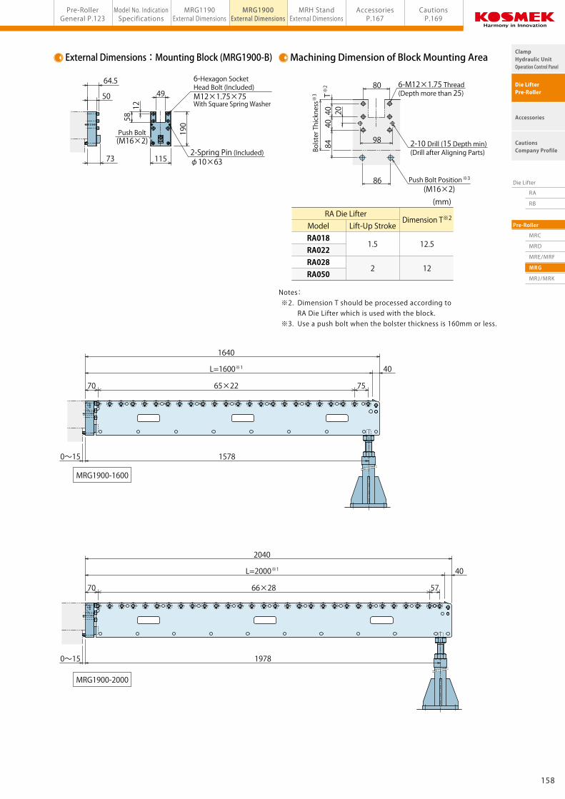
CautionsP.169model MRG/MRHPre-Roller Removable Type (With Stand)
Model No. Indication:Removable Pre-Roller (With Stand)
1 2 3 4
MR G 119 0 - 710
4
3
Die Travel L・Mounting Block Type
1 Frame Storage Type
0 : Revision Number
Design No.
P.125
P.135
P.145
P.145
P.153
P.161
P.161
G
Applicable Bolster Height
Model No. Indication:Stand
1 2
MRH 040 0 - A
1 Applicable Bolster Height
2
0 : Revision Number
Design No.
Compatible Mounting BlocksPre-Roller Model No.
MRG1190-□
MRG1900-□
Mounting Block Model
MRG1190-B
MRG1900-B
Mounting Block Weight (kg)
3.7
7.1
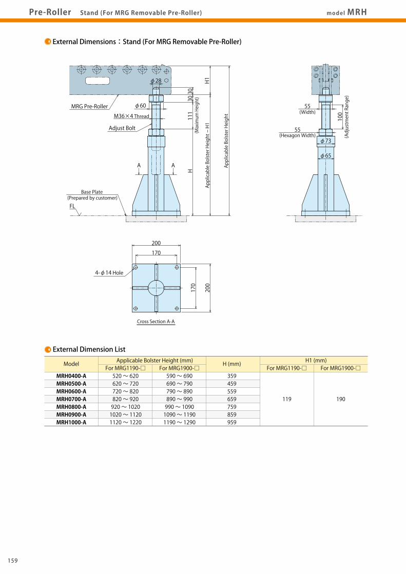
Notes on Handling 1. MRH Stand can be used only for MRG Pre-Roller. Do not use it for any other use. (Cannot be used for MRC or MRD Pre-Roller.) 2. When setting MRH Stand, make sure it is vertical to the floor. 3. Fix MRH Stand to the floor and make sure MRG Pre-Roller is level. 4. Do not adjust bolts beyond the maximum adjusting height.
Installation Notes 1. The floor should be level. 2. The floor should be strong enough to support the maximum die weight (5.25N/mm2). (1) If the floor is made of concrete or mortar, set a base plate such as an iron plate in order to withstand load. (2) When MRH Stand is set on the pit cover, set joists or poles just under the cover to support the stand. 3. MRH Stand has to be fixed to the floor.
Note: 1. MRG Pre-Roller, MRG-B Mounting Block and MRH Stand are sold separately. Order by type and number required. 040 : 520 ~ 620 mm
050 : 620 ~ 720 mm
060 : 720 ~ 820 mm
070 : 820 ~ 920 mm
080 : 920 ~ 1020 mm
090 : 1020 ~ 1120 mm
100 : 1120 ~ 1220 mm
・ When using MRG1190-□
040 : 590 ~ 690 mm
050 : 690 ~ 790 mm
060 : 790 ~ 890 mm
070 : 890 ~ 990 mm
080 : 990 ~ 1090 mm
090 : 1090 ~ 1190 mm
100 : 1190 ~ 1290 mm
・ When using MRG1900-□
Mounting Block
Die Travel to Stop LRemovable Pre-Roller(With Stand)
Stand
Applicable Bolster Height
Stand
Stand
Specifications:Removable Pre-Roller (With Stand)
Die Travel to Stop L
L/2 L/2
L×7/10
Uniform Load
Model No. Weight (kg) Number of Rollers Die Travel to StopL (mm)
When using MRG1190-□520 ~ 620620 ~ 720720 ~ 820820 ~ 920920 ~ 10201020 ~ 11201120 ~ 1220
Model No. Weight (kg) Number of Rollers Die Travel to StopL (mm)
Max. Loading Weight each (kg)※1
MRG1900-1000MRG1900-1250MRG1900-1600MRG1900-2000
29.637.247.759.8
15182430
1000125016002000
4915390030502400
MRG1190-□
MRG1900-□
Note: ※1. The maximum loading weight per pre-roller with a uniform load at the center of die travel L and 70 % length of the die travel L.
119 : Mounting Block Height 119 mm
190 : Mounting Block Height 190 mm
2 Mounting Block Height (Pre-Roller Height)
Mounting Block Height
Mounting Block
Dimensions : Die Travel L (Distance that the die can be pulled out)
(Please refer to the specifications)
B : Mounting Block
C : Removable Type
D : Removable・Vertical Folding Type
E : Horizontal Folding Type (Inside Arm)
F : Horizontal Folding Type (Outside Arm)
G : Removable Type (With Stand)
J : Horizontal Folding Type (With Stand) (Inside Arm)
K : Horizontal Folding Type (With Stand) (Outside Arm)
154153
RA
RB
MRC
MRD
MRE/MRF
MRG
MRJ/MRK
Die Lifter
Pre-Roller
ClampHydraulic UnitOperation Control Panel
Die LifterPre-Roller
Accessories
CautionsCompany Profile
Model No. IndicationSpecifications
MRG1190External Dimensions
MRG1900External Dimensions
MRH StandExternal Dimensions
Pre-RollerGeneral P.123
AccessoriesP.167
CautionsP.169model MRG/MRHPre-Roller Removable Type (With Stand)
Model No. Indication:Removable Pre-Roller (With Stand)
1 2 3 4
MR G 119 0 - 710
4
3
Die Travel L・Mounting Block Type
1 Frame Storage Type
0 : Revision Number
Design No.
P.125
P.135
P.145
P.145
P.153
P.161
P.161
G
Applicable Bolster Height
Model No. Indication:Stand
1 2
MRH 040 0 - A
1 Applicable Bolster Height
2
0 : Revision Number
Design No.
Compatible Mounting BlocksPre-Roller Model No.
MRG1190-□
MRG1900-□
Mounting Block Model
MRG1190-B
MRG1900-B
Mounting Block Weight (kg)
3.7
7.1
Notes on Handling 1. MRH Stand can be used only for MRG Pre-Roller. Do not use it for any other use. (Cannot be used for MRC or MRD Pre-Roller.) 2. When setting MRH Stand, make sure it is vertical to the floor. 3. Fix MRH Stand to the floor and make sure MRG Pre-Roller is level. 4. Do not adjust bolts beyond the maximum adjusting height.
Installation Notes 1. The floor should be level. 2. The floor should be strong enough to support the maximum die weight (5.25N/mm2). (1) If the floor is made of concrete or mortar, set a base plate such as an iron plate in order to withstand load. (2) When MRH Stand is set on the pit cover, set joists or poles just under the cover to support the stand. 3. MRH Stand has to be fixed to the floor.
Note: 1. MRG Pre-Roller, MRG-B Mounting Block and MRH Stand are sold separately. Order by type and number required. 040 : 520 ~ 620 mm
050 : 620 ~ 720 mm
060 : 720 ~ 820 mm
070 : 820 ~ 920 mm
080 : 920 ~ 1020 mm
090 : 1020 ~ 1120 mm
100 : 1120 ~ 1220 mm
・ When using MRG1190-□
040 : 590 ~ 690 mm
050 : 690 ~ 790 mm
060 : 790 ~ 890 mm
070 : 890 ~ 990 mm
080 : 990 ~ 1090 mm
090 : 1090 ~ 1190 mm
100 : 1190 ~ 1290 mm
・ When using MRG1900-□
Mounting Block
Die Travel to Stop LRemovable Pre-Roller(With Stand)
Stand
Applicable Bolster Height
Stand
Stand
Specifications:Removable Pre-Roller (With Stand)
Die Travel to Stop L
L/2 L/2
L×7/10
Uniform Load
Model No. Weight (kg) Number of Rollers Die Travel to StopL (mm)
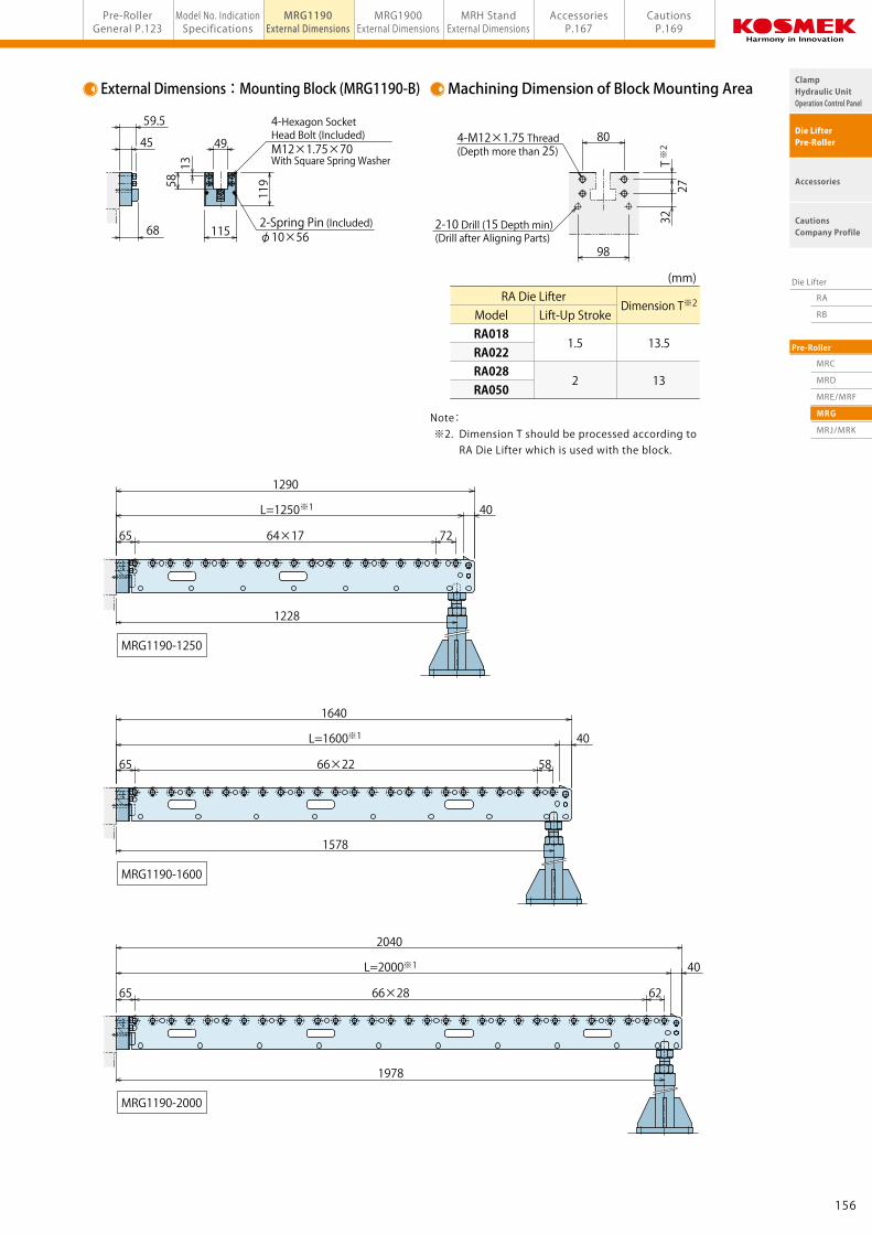
Notes: ※2. Dimension T should be processed according to RA Die Lifter which is used with the block. ※3. Use a push bolt when the bolster thickness is 160mm or less.
12
64.5
(mm)
6-M12×1.75 Thread (Depth more than 25)
Push Bolt Position
2-10 Drill (15 Depth min) (Drill after Aligning Parts)Bo
lster Thickness
2-Spring Pin (Included)φ10×63
6-Hexagon Socket Head Bolt (Included)M12×1.75×75With Square Spring Washer
※3
158157
RA
RB
MRC
MRD
MRE/MRF
MRG
MRJ/MRK
Die Lifter
Pre-Roller
ClampHydraulic UnitOperation Control Panel
Die LifterPre-Roller
Accessories
CautionsCompany Profile
Model No. IndicationSpecifications
MRG1190External Dimensions
MRG1900External Dimensions
MRH StandExternal Dimensions
Pre-RollerGeneral P.123
AccessoriesP.167
CautionsP.169model MRG1900Pre-Roller Removable Type (With Stand)
External Dimensions:Mounting Block (MRG1900-B) Machining Dimension of Block Mounting Area
Notes: ※2. Dimension T should be processed according to RA Die Lifter which is used with the block. ※3. Use a push bolt when the bolster thickness is 160mm or less.
12
64.5
(mm)
6-M12×1.75 Thread (Depth more than 25)
Push Bolt Position
2-10 Drill (15 Depth min) (Drill after Aligning Parts)Bo
lster Thickness
2-Spring Pin (Included)φ10×63
6-Hexagon Socket Head Bolt (Included)M12×1.75×75With Square Spring Washer
※3
158157
RA
RB
MRC
MRD
MRE/MRF
MRG
MRJ/MRK
Die Lifter
Pre-Roller
ClampHydraulic UnitOperation Control Panel
Die LifterPre-Roller
Accessories
CautionsCompany Profile
Model No. IndicationSpecifications
MRG1190External Dimensions
MRG1900External Dimensions
MRH StandExternal Dimensions
Pre-RollerGeneral P.123
AccessoriesP.167
CautionsP.169Pre-Roller Stand (For MRG Removable Pre-Roller) model MRH
Model No. Weight (kg) No. of RollersMRJ MRK Die Travel to Stop
L (mm) Max. Loading Weight each (kg)※1
MRJ2950-800MRJ2950-900MRJ2950-1000MRJ2950-1250
44.547.650.356.6
13151722
Model No. Weight (kg) No. of RollersMRK2950-800MRK2950-900MRK2950-1000MRK2950-1250
47.851.254.060.5
13151722
80090010001250
4915410035502675
Note: ※1. The maximum loading weight per pre-roller with a uniform load at the center of die travel L and 70 % length of the die travel L.
L/2 L/2
L×7/10
Uniform Load
Notes on Handling 1. MRL Stand can be used only for MRJ / MRK Pre-Roller. Do not use it for any other use. (Cannot be used for MRE or MRF Pre-Roller.) 2. When setting MRL Stand, make sure it is vertical to the floor. 3. Adjust MRL Stand to the floor. 4. Do not adjust bolts beyond the maximum adjusting height. 5. Do not operate a press machine when MRJ, MRK Pre-Roller are stowed on the floor with MRL Stand. The vibration of press machine could damage the pre-roller.
Installation Notes 1. The floor should be level. 2. The floor should be strong enough to support the maximum die weight (5.25N/mm2). (1) If the floor is made of concrete or mortar, set a base plate such as an iron plate in order to withstand load. (2) When MRL Stand is set on the pit cover, set joists or poles just under the cover to support the stand.
Folding Method
②Pull the Lock Pin Releasing Lever① Adjust MRL Stand to make clearance between the stand and floor. ③Fold the Roller Arm
Lock Pin Releasing Lever
MRL Stand
※. Can be folded to the other side as well.
4
3
Die Travel L
1 Frame Storage Type
295 : Mounting Part Height 295mm
0 : Revision Number
Design No.
2 Mounting Part Height (Pre-Roller Height)
Mounting Part Height
(Pre-Roller Height)
Applicable Bolster Height
Model No. Indication:Stand
1 2
MRL 060 0 - A
1 Applicable Bolster Height
2
0 : Revision Number
Design No.
Dimensions : Die Travel L
(Distance that the die can be pulled out)
(Please refer to the specifications)
060 : Applicable Bolster Height 710 ~ 810 mm
070 : Applicable Bolster Height 810 ~ 910 mm
080 : Applicable Bolster Height 910 ~ 1010 mm
090 : Applicable Bolster Height 1010 ~ 1110 mm
100 : Applicable Bolster Height 1110 ~ 1210 mm
110 : Applicable Bolster Height 1210 ~ 1310 mm
120 : Applicable Bolster Height 1310 ~ 1410 mm
Die Travel to Stop L Horizontal FoldingPre-Roller(With Stand)
Stand
Stand
C : Removable Type
D : Removable・Vertical Folding Type
E : Horizontal Folding Type (Inside Arm)
F : Horizontal Folding Type (Outside Arm)
G : Removable Type (With Stand)
J : Horizontal Folding Type (With Stand) (Inside Arm)
K : Horizontal Folding Type (With Stand) (Outside Arm)
162161
RA
RB
MRC
MRD
MRE/MRF
MRG
MRJ/MRK
Die Lifter
Pre-Roller
ClampHydraulic UnitOperation Control Panel
Die LifterPre-Roller
Accessories
CautionsCompany Profile
Pre-RollerGeneral P.123
Model No. IndicationSpecifications
MRJ/MRK2950External Dimensions
MRL StandExternal Dimensions
AccessoriesP.167
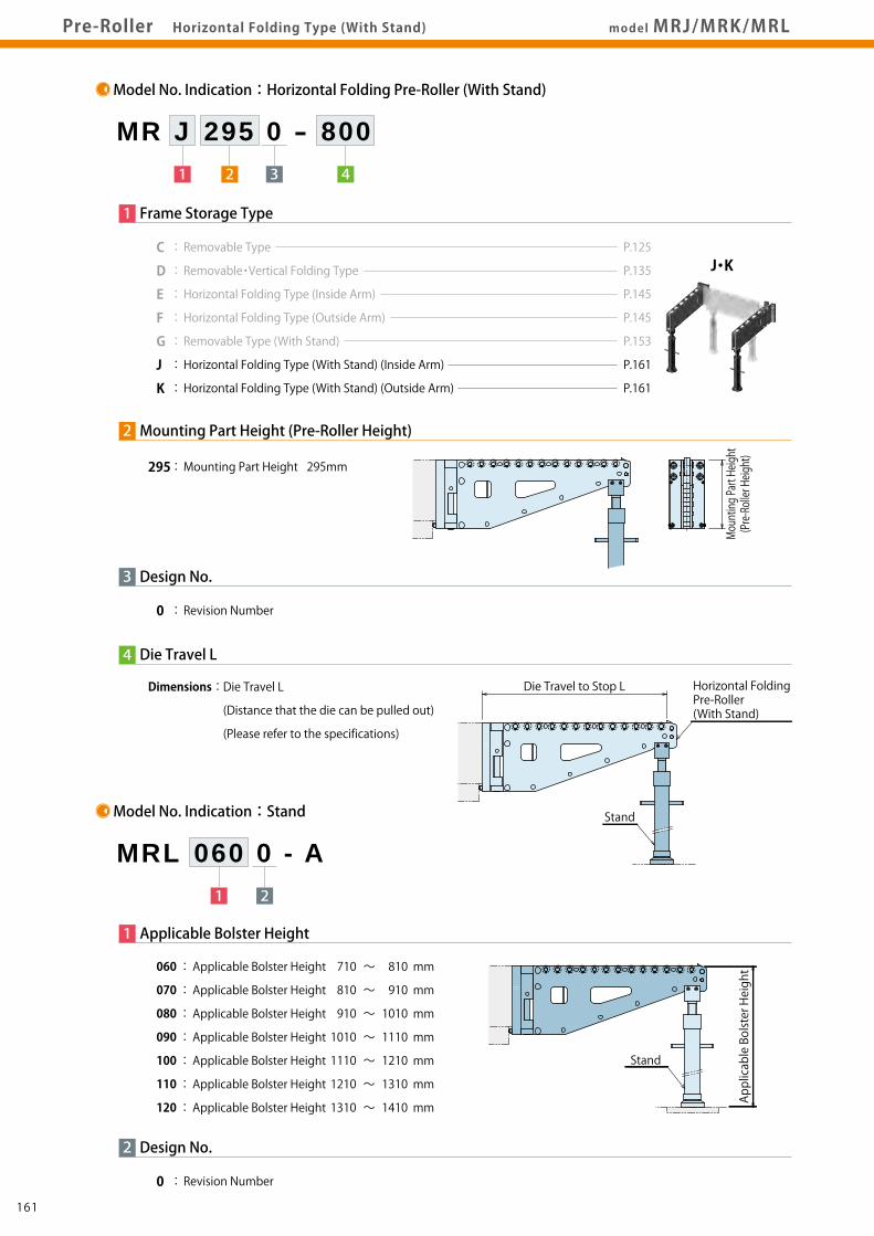
CautionsP.169Pre-Roller Horizontal Folding Type (With Stand) model MRJ/MRK/MRL
Model No. Indication:Horizontal Folding Pre-Roller (With Stand)
Model No. Weight (kg) No. of RollersMRJ MRK Die Travel to Stop
L (mm) Max. Loading Weight each (kg)※1
MRJ2950-800MRJ2950-900MRJ2950-1000MRJ2950-1250
44.547.650.356.6
13151722
Model No. Weight (kg) No. of RollersMRK2950-800MRK2950-900MRK2950-1000MRK2950-1250
47.851.254.060.5
13151722
80090010001250
4915410035502675
Note: ※1. The maximum loading weight per pre-roller with a uniform load at the center of die travel L and 70 % length of the die travel L.
L/2 L/2
L×7/10
Uniform Load
Notes on Handling 1. MRL Stand can be used only for MRJ / MRK Pre-Roller. Do not use it for any other use. (Cannot be used for MRE or MRF Pre-Roller.) 2. When setting MRL Stand, make sure it is vertical to the floor. 3. Adjust MRL Stand to the floor. 4. Do not adjust bolts beyond the maximum adjusting height. 5. Do not operate a press machine when MRJ, MRK Pre-Roller are stowed on the floor with MRL Stand. The vibration of press machine could damage the pre-roller.
Installation Notes 1. The floor should be level. 2. The floor should be strong enough to support the maximum die weight (5.25N/mm2). (1) If the floor is made of concrete or mortar, set a base plate such as an iron plate in order to withstand load. (2) When MRL Stand is set on the pit cover, set joists or poles just under the cover to support the stand.
Folding Method
②Pull the Lock Pin Releasing Lever① Adjust MRL Stand to make clearance between the stand and floor. ③Fold the Roller Arm
Lock Pin Releasing Lever
MRL Stand
※. Can be folded to the other side as well.
4
3
Die Travel L
1 Frame Storage Type
295 : Mounting Part Height 295mm
0 : Revision Number
Design No.
2 Mounting Part Height (Pre-Roller Height)
Mounting Part Height
(Pre-Roller Height)
Applicable Bolster Height
Model No. Indication:Stand
1 2
MRL 060 0 - A
1 Applicable Bolster Height
2
0 : Revision Number
Design No.
Dimensions : Die Travel L
(Distance that the die can be pulled out)
(Please refer to the specifications)
060 : Applicable Bolster Height 710 ~ 810 mm
070 : Applicable Bolster Height 810 ~ 910 mm
080 : Applicable Bolster Height 910 ~ 1010 mm
090 : Applicable Bolster Height 1010 ~ 1110 mm
100 : Applicable Bolster Height 1110 ~ 1210 mm
110 : Applicable Bolster Height 1210 ~ 1310 mm
120 : Applicable Bolster Height 1310 ~ 1410 mm
Die Travel to Stop L Horizontal FoldingPre-Roller(With Stand)
Stand
Stand
C : Removable Type
D : Removable・Vertical Folding Type
E : Horizontal Folding Type (Inside Arm)
F : Horizontal Folding Type (Outside Arm)
G : Removable Type (With Stand)
J : Horizontal Folding Type (With Stand) (Inside Arm)
K : Horizontal Folding Type (With Stand) (Outside Arm)
162161
RA
RB
MRC
MRD
MRE/MRF
MRG
MRJ/MRK
Die Lifter
Pre-Roller
ClampHydraulic UnitOperation Control Panel
Die LifterPre-Roller
Accessories
CautionsCompany Profile
Model No. IndicationSpecifications
MRJ/MRK2950External Dimensions
MRL StandExternal Dimensions
Pre-RollerGeneral P.123
AccessoriesP.167
CautionsP.169Pre-Roller Horizontal Folding Type (With Stand) model MRJ/MRK2950
2-10 Drill (15 Depth min) (Drill after Aligning Parts)
Push Bolt Position※3
※2
Stopper
28
155
295
Push Bolt(M16×2)
2-Spring Pin (Included)φ10×50
4-Hexagon Socket Head Bolt (Included)M16×2×50With JIS Spring Washer
Enlarged View of B (Front End)View A(Same for MRJ/MRK)
36
29 47
70.5
φ100
124.5
64.5
Minimum Mounting Distance=L+50
174.5 114.5
MRJ2950 MRK2950
Notes: ※2. Dimension T should be processed according to RA Die Lifter which is used with the block. ※3. Use a push bolt when the bolster thickness is 245mm or less.
20
(mm)
4-M16×2 Thread (Depth more than 35)
Bolster Thickness※3
164163
RA
RB
MRC
MRD
MRE/MRF
MRG
MRJ/MRK
Die Lifter
Pre-Roller
ClampHydraulic UnitOperation Control Panel
Die LifterPre-Roller
Accessories
CautionsCompany Profile
Model No. IndicationSpecifications
MRJ/MRK2950External Dimensions
MRL StandExternal Dimensions
Pre-RollerGeneral P.123
AccessoriesP.167
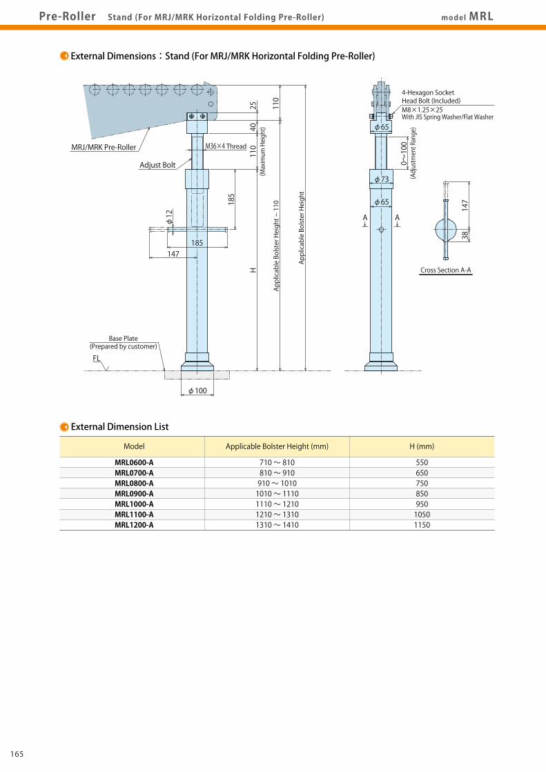
CautionsP.169Pre-Roller Stand (For MRJ/MRK Horizontal Folding Pre-Roller) model MRL
4-Hexagon Socket Head Bolt (Included)M8×1.25×25With JIS Spring Washer/Flat Washer
166165
RA
RB
MRC
MRD
MRE/MRF
MRG
MRJ/MRK
Die Lifter
Pre-Roller
ClampHydraulic UnitOperation Control Panel
Die LifterPre-Roller
Accessories
CautionsCompany Profile
Pre-RollerGeneral P.123
Accessories CautionsP.169Pre-Roller Accessories model MRC-S/MRC-E
Spacer Block Model No.
MRC0750-S
MRC1190-S
MRC1500-S
MRC1900-S
MRE1190-S
MRE1900-S
MRE2950-S
Compatible Pre-Roller Model No.MRC0750-□MRD0750-□MRC1190-□MRD1190-□MRG1190-□MRC1500-□MRD1500-□MRC1900-□MRD1900-□MRG1900-□MRE1190-□MRF1190-□MRE1900-□MRF1900-□MRE2950-□MRF2950-□MRJ2950-□MRK2950-□
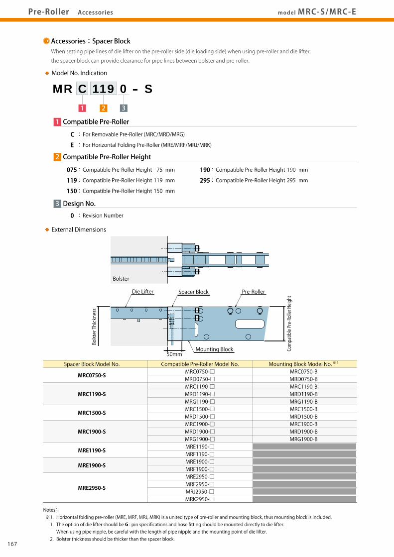
Notes: ※1. Horizontal folding pre-roller (MRE, MRF, MRJ, MRK) is a united type of pre-roller and mounting block, thus mounting block is included. 1. The option of die lifter should be G : pin specifications and hose fitting should be mounted directly to die lifter. When using pipe nipple, be careful with the length of pipe nipple and the mounting point of die lifter. 2. Bolster thickness should be thicker than the spacer block.
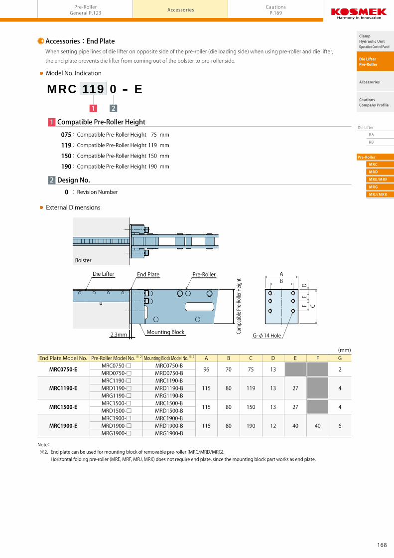
Note: ※2. End plate can be used for mounting block of removable pre-roller (MRC/MRD/MRG). Horizontal folding pre-roller (MRE, MRF, MRJ, MRK) does not require end plate, since the mounting block part works as end plate.
Accessories:Spacer BlockWhen setting pipe lines of die lifter on the pre-roller side (die loading side) when using pre-roller and die lifter,
the spacer block can provide clearance for pipe lines between bolster and pre-roller.
1 2 3
MR C 119 0 - S
3
0 : Revision Number
Design No.
1 Compatible Pre-Roller
C : For Removable Pre-Roller (MRC/MRD/MRG)
E : For Horizontal Folding Pre-Roller (MRE/MRF/MRJ/MRK)
2 Compatible Pre-Roller Height
Accessories:End PlateWhen setting pipe lines of die lifter on opposite side of the pre-roller (die loading side) when using pre-roller and die lifter,
the end plate prevents die lifter from coming out of the bolster to pre-roller side.
Accessories CautionsP.169Pre-Roller Accessories model MRC-S/MRC-E
Spacer Block Model No.
MRC0750-S
MRC1190-S
MRC1500-S
MRC1900-S
MRE1190-S
MRE1900-S
MRE2950-S
Compatible Pre-Roller Model No.MRC0750-□MRD0750-□MRC1190-□MRD1190-□MRG1190-□MRC1500-□MRD1500-□MRC1900-□MRD1900-□MRG1900-□MRE1190-□MRF1190-□MRE1900-□MRF1900-□MRE2950-□MRF2950-□MRJ2950-□MRK2950-□
Notes: ※1. Horizontal folding pre-roller (MRE, MRF, MRJ, MRK) is a united type of pre-roller and mounting block, thus mounting block is included. 1. The option of die lifter should be G : pin specifications and hose fitting should be mounted directly to die lifter. When using pipe nipple, be careful with the length of pipe nipple and the mounting point of die lifter. 2. Bolster thickness should be thicker than the spacer block.
Note: ※2. End plate can be used for mounting block of removable pre-roller (MRC/MRD/MRG). Horizontal folding pre-roller (MRE, MRF, MRJ, MRK) does not require end plate, since the mounting block part works as end plate.
Accessories:Spacer BlockWhen setting pipe lines of die lifter on the pre-roller side (die loading side) when using pre-roller and die lifter,
the spacer block can provide clearance for pipe lines between bolster and pre-roller.
1 2 3
MR C 119 0 - S
3
0 : Revision Number
Design No.
1 Compatible Pre-Roller
C : For Removable Pre-Roller (MRC/MRD/MRG)
E : For Horizontal Folding Pre-Roller (MRE/MRF/MRJ/MRK)
2 Compatible Pre-Roller Height
Accessories:End PlateWhen setting pipe lines of die lifter on opposite side of the pre-roller (die loading side) when using pre-roller and die lifter,
the end plate prevents die lifter from coming out of the bolster to pre-roller side.
① Secure the block to the edge of the bolster with attached mounting bolt.
② Mount pre-roller and use shims to level the roller surface.
③ With the die lifter inside the bolster in the lifted position, adjust the
position of the mounting block so that the top of the rollers on the
die lifter and pre-roller are level and then perform the final
tightening of mounting bolts.
④ Be sure to position the block with a spring pin.
Without a spring pin, the pre-roller could be misaligned,
and the die could fall off the rollers.
※ If rollers are not set in the bolster, adjust the roller surface
of the pre-roller to be level with the bolster surface.
3)Mounting the Hook (MRD Roller Only)
● Align the pin of the hook with the hole on the block
and mount the hook with the attached mounting bolt.
Mounting Bolt Tightening Torque
2)Level Adjustment
● Use shims to adjust the front end roller (roller A) of the pre-roller
to be approximately 2mm higher than the bolster surface.
● Installation Notes
About
2mm
Cautions
● Notes for Design
1)Check Specifications
● Please use each product according to its specifications.
2)Check the Die Weight
● Make sure the die weight is less than the maximum loading weight.
3)Check the Die Dimensions
● Make sure that the length of the die from front to back is
at least twice as long as the distance between the first roller
of the die lifter (closest to the pre-roller) and the last roller
of the pre-roller (closest to the die lifter).
If the length of the die is less than double the distance
between rollers, the transition will not be smooth,
and it could result in damage to the die of equipment.
1)It should be handled by qualified personnel.
2)The pre-roller should not be used for purposes other than
die changes.
3)Only use dies that weigh less than the maximum load.
4)Stow the pre-roller away while operating the press machine.
● Fold or remove the pre-roller while operating the press machine.
If the press machine is operated with the pre-roller in place,
the vibration could damage the pre-roller.
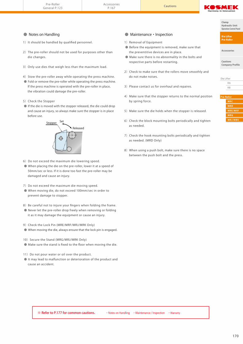
5)Check the Stopper
● If the die is moved with the stopper released, the die could drop
and cause an injury, so always make sure the stopper is in place
before use.
6)Do not exceed the maximum die lowering speed.
● When placing the die on the pre-roller, lower it at a speed of
50mm/sec or less. If it is done too fast the pre-roller may be
damaged and cause an injury.
7)Do not exceed the maximum die moving speed.
● When moving die, do not exceed 100mm/sec in order to
prevent damage to stopper.
8)Be careful not to injure your fingers when folding the frame.
● Never let the pre-roller drop freely when removing or folding
it as it may damage the equipment or cause an injury.
9)Check the Lock Pin (MRE/MRF/MRJ/MRK Only)
● When moving the die, always ensure that the lock pin is engaged.
10)Secure the Stand (MRG/MRJ/MRK Only)
● Make sure the stand is fixed to the floor when moving the die.
11)Do not pour water or oil over the product.
● It may lead to malfunction or deterioration of the product and
cause an accident.
・Notes on Handling ・Maintenance / Inspection ・ Warranty※ Refer to P.177 for common cautions.
● Maintenance・Inspection
1)Removal of Equipment
● Before the equipment is removed, make sure that
the preventitive devices are in place.
● Make sure there is no abnormality in the bolts and
respective parts before restarting.
2)Check to make sure that the rollers move smoothly and
do not make noises.
3)Please contact us for overhaul and repaires.
4)Make sure that the stopper returns to the normal position
by spring force.
5)Make sure the die holds when the stopper is released.
6)Check the block mounting bolts periodically and tighten
as needed.
7)Check the hook mounting bolts periodically and tighten
as needed. (MRD Only)
8)When using a push bolt, make sure there is no space
between the push bolt and the press.
Length of Die from Front to Back
Distance between Rollers
Pre-RollerDie Lifter
Bolster
Tightening Torque (N・m)
98
200
Mounting Bolt Size
M12×1.75
M16×2
Model No.MR□0750MR□1190MR□1500MR□1900MR□2950
Tightening Torque (N・m)50
98
Mounting Bolt SizeM10×1.5
M12×1.75
Model No.MRD0750MRD1190MRD1500MRD1900
Stopper Set
Released
Block Hook
Mounting Bolt
PinPin Hole
Hook Mounted
Pin HoleMounting Bolt
Shim
Mounting Bolt
Hole for PositioningSpring Pin
Roller A
Level Adjusting Shim
170169
Notes on Hydraulic CylinderSpeed Control Unit
Cautions
Hydraulic Fluid List
Notes on Handling
Maintenance / Inspection
Warranty
Company Profile
Company Profile
Our Products
History
Sales Office
ClampHydraulic UnitOperation Control Panel
Die LifterPre-Roller
Accessories
CautionsCompany Profile
CautionsInstallation Notes
(For Hydraulic Series) Hydraulic Fluid ListInstallation Notes(For Hydraulic Series) Maintenance / Inspection WarrantyNotes on HandlingHydraulic Fluid List Notes on Hydraulic Cylinder
Speed Control Unit
Installation Notes(For Hydraulic Series)
Cautions
● Installation Notes (Cautions for Hydraulic Series)
1)Check the fluid to use
● Please use the appropriate fluid by referring to the Hydraulic Fluid List.
● If hydraulic oil with viscosity grade higher than ISO-VG-32 is used, action time would be longer. ● If using it at low temperature, action time will be longer because the viscosity of hydraulic oil becomes higher.
2)Procedure before Piping
● The pipeline, piping connector and fixture circuits should be
cleaned by thorough flushing.
● The dust and cutting chips in the circuit may lead to fluid
leakage and malfunction.
● Our products except some valves are not equipped with
protective function to prevent dust and cutting chips going
into the hydraulic system and pipeline.
3)Applying Sealing Tape
● Wrap with tape 1 to 2 times following the screwing direction.
● Pieces of the sealing tape can lead to air leaks and malfunction.
● In order to prevent a foreign substance from going into
the product during piping, it should be carefully cleaned.
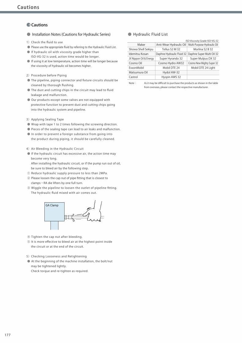
4)Air Bleeding in the Hydraulic Circuit
● If the hydraulic circuit has excessive air, the action time may
become very long.
After installing the hydraulic circuit, or if the pump run out of oil,
be sure to bleed air by the following step.
① Reduce hydraulic supply pressure to less than 2MPa.
② Please loosen the cap nut of pipe fitting that is closest to
clamps・RA die lifters by one full turn.
③ Wiggle the pipeline to loosen the outlet of pipeline fitting.
The hydraulic fluid mixed with air comes out.
④ Tighten the cap nut after bleeding.
⑤ It is more effective to bleed air at the highest point inside
the circuit or at the end of the circuit.
5)Checking Looseness and Retightening
● At the beginning of the machine installation, the bolt/nut
For spring return single acting cylinders, restricting flow
during release can extremely slow down or disrupt release action.
The preferred method is to control the flow during the lock action
using a valve that has free-flow in the release direction.
It is also preferred to provide a flow control valve at each actuator.
Accelerated clamping speed by excessive hydraulic flow to
the cylinder may sustain damage. In this case add flow control to
regulate flow.
● Flow Control Circuit for Double Acting Cylinder
Flow control circuit for double acting cylinder should have meter-out
circuits for both the lock and release sides. Meter-in control can
have adverse effect by presence of air in the system.
【Meter-out Circuit】
【Meter-in Circuit】
In the case of meter-out circuit, the hydraulic circuit should
be designed with the following points.
① Single acting components should not be used in the same
flow control circuit as the double acting components.
The release action of the single acting cylinders may become
erratic or very slow.
Refer to the following circuit when both the single acting
cylinder and double acting cylinder are used together.
○ Separate the control circuit.
○ Reduce the influence of double acting cylinder control unit.
However, due to the back pressure in tank line, single action
cylinder is activated after double action cylinder works.
② In the case of meter-out circuit, the inner circuit pressure may
increase during the cylinder action because of the fluid supply.
The increase of the inner circuit pressure can be prevented by
reducing the supplied fluid beforehand via the flow control valve.
Especially when using sequence valve or pressure switches for
clamping detection. If the back pressure is more than the set
pressure then the system will not work as it is designed to.
Flow Control at the Release Side
W
Flow Control Valve(Any location is OK)
Sequence Valve
● Notes on Hydraulic Cylinder Speed Control Unit
Please pay attention to the cautions below. Design the hydraulic circuit for controlling the action speed of hydraulic cylinder.
Improper circuit design may lead to malfunctions and damages. Please review the circuit design in advance.!
GA Clamp
178177
Notes on Hydraulic CylinderSpeed Control Unit
Cautions
Hydraulic Fluid List
Notes on Handling
Maintenance / Inspection
Warranty
Company Profile
Company Profile
Our Products
History
Sales Office
ClampHydraulic UnitOperation Control Panel
Die LifterPre-Roller
Accessories
CautionsCompany Profile
CautionsInstallation Notes
(For Hydraulic Series) Hydraulic Fluid ListInstallation Notes(For Hydraulic Series) Maintenance / Inspection WarrantyNotes on HandlingHydraulic Fluid List Notes on Hydraulic Cylinder
Speed Control Unit
Installation Notes(For Hydraulic Series)
Cautions
● Installation Notes (Cautions for Hydraulic Series)
1)Check the fluid to use
● Please use the appropriate fluid by referring to the Hydraulic Fluid List.
● If hydraulic oil with viscosity grade higher than ISO-VG-32 is used, action time would be longer. ● If using it at low temperature, action time will be longer because the viscosity of hydraulic oil becomes higher.
2)Procedure before Piping
● The pipeline, piping connector and fixture circuits should be
cleaned by thorough flushing.
● The dust and cutting chips in the circuit may lead to fluid
leakage and malfunction.
● Our products except some valves are not equipped with
protective function to prevent dust and cutting chips going
into the hydraulic system and pipeline.
3)Applying Sealing Tape
● Wrap with tape 1 to 2 times following the screwing direction.
● Pieces of the sealing tape can lead to air leaks and malfunction.
● In order to prevent a foreign substance from going into
the product during piping, it should be carefully cleaned.
4)Air Bleeding in the Hydraulic Circuit
● If the hydraulic circuit has excessive air, the action time may
become very long.
After installing the hydraulic circuit, or if the pump run out of oil,
be sure to bleed air by the following step.
① Reduce hydraulic supply pressure to less than 2MPa.
② Please loosen the cap nut of pipe fitting that is closest to
clamps・RA die lifters by one full turn.
③ Wiggle the pipeline to loosen the outlet of pipeline fitting.
The hydraulic fluid mixed with air comes out.
④ Tighten the cap nut after bleeding.
⑤ It is more effective to bleed air at the highest point inside
the circuit or at the end of the circuit.
5)Checking Looseness and Retightening
● At the beginning of the machine installation, the bolt/nut