Precision Cutting of Structured Ceramic Molds with Micro PCD Milling Tool Hirofumi SUZUKI * , Tatsuya FURUKI * , Mutsumi OKADA * , Katsuji FUJII ** , Takashi GOTO ** * Chubu University 1200, Matsumoto, Kasugai, Aichi, 487-8501, Japan E-mail: [email protected]** NS Tool Co. Ltd. 2-11, Matsuzakataira, Taiwa-cho, Kurokawa, Miyagi, 981-3408, Japan [Received Jan **, 2011; accepted *** **, 2011] In order to machine micro structured dies and molds made of ceramics, micro milling tools made of poly-crystalline diamond (PCD) are developed. Many cutting edges are ground with diamond wheels. Tool wears of the PCD milling tool are evaluated by cutting spherical molds made of binder-less tungsten carbide and structured surfaces are machined for trial. From the experiments, it is clarified that the tool life of the PCD milling tool is more than 10 times compared with a resinoid diamond grinding wheel and the form accuracy obtained was 0.1 - 0.3 μm P-V and the surface roughness was 10 nm Rz. Keywords: cutting, micro milling tool, poly-crystalline diamond, tungsten carbide, tool ware, surface roughness 1. Introduction Demands are increasing for micro structured components to be installed in various optical devices such as digital cameras and blue laser pick-up devices, medical devices such as micro channel, and solar system. Ceramic molds are used to increase the mold life. The ceramic dies and molds are mostly ground with micro diamond wheels [1-3]. The diamond wheel must be trued carefully on the machine before grinding, however the grinding wheel wears so much and it is difficult to keep the original sharp shape of the wheel and to machine the structured surface. As the size of the dies and molds becomes smaller and the required accuracy becomes higher, it is, therefore expected that the ceramic dies and molds could be finished with high accuracy by a proper diamond milling tool. In order to machine micro aspheric molds and dies made of ceramics, micro milling tools made of polycrystalline diamond (PCD) are developed. In this cutting method, the materials are removed by interrupted cutting and the tool wear can be reduced. It is therefore expected that the hard ceramic can be cut with micro milling tool [4]. In this study, some micro milling tools made of PCD was made in trial and basic cutting characteristics of the tool life are evaluated by milling hard tungsten carbide. And a feasibility study of a precision structured cutting was carried out. 2. Fundamental cutting experiment 2.1. PCD micro milling tool Fig.1 shows a PCD micro milling tool machined for evaluating of basic cutting characteristics and the specifications are shown in Table 1. The tools outer diameter was Φ1mm and 40 cutting edges were ground on the tool edge. The PCD micro milling tool was fabricated as shown in Fig. 2. At first the PCD wafer was bonded with a silver alloy on to a cemented carbide substrate and the bonded
2-11, Matsuzakataira, Taiwa-cho, Kurokawa, Miyagi, 981-3408, Japan [Received Jan **, 2011; accepted *** **, 2011]
In order to machine micro structured dies and molds made of ceramics, micro milling tools made of poly-crystalline diamond (PCD) are developed. Many cutting edges are ground with diamond wheels. Tool wears of the PCD milling tool are evaluated by cutting spherical molds made of binder-less tungsten carbide and structured surfaces are machined for trial. From the experiments, it is clarified that the tool life of the PCD milling tool is more than 10 times compared with a resinoid diamond grinding wheel and the form accuracy obtained was 0.1 - 0.3 µm P-V and the surface roughness was 10 nm Rz. Keywords: cutting, micro milling tool, poly-crystalline diamond, tungsten carbide, tool ware, surface roughness 1. Introduction
Demands are increasing for micro structured components to be installed in various optical devices such as digital cameras and blue laser pick-up devices, medical devices such as micro channel, and solar system. Ceramic molds are used to increase the mold life. The ceramic dies and molds are mostly ground with micro diamond wheels [1-3]. The diamond wheel must be trued carefully on the machine before grinding, however the grinding wheel wears so much and it is difficult to keep the original sharp shape of the wheel and to machine the structured surface.
As the size of the dies and molds becomes smaller and the required accuracy becomes higher, it is, therefore expected that the ceramic dies and molds could be finished with high accuracy by a proper diamond milling tool. In order to machine micro aspheric molds and dies made of ceramics, micro milling tools made of polycrystalline diamond (PCD) are developed. In this cutting method, the materials are removed by interrupted cutting and the tool wear can be reduced. It is therefore expected that the hard ceramic can be cut with micro milling tool [4].
In this study, some micro milling tools made of PCD was made in trial and basic cutting characteristics of the tool life are evaluated by milling hard tungsten carbide. And a feasibility study of a precision structured cutting was carried out. 2. Fundamental cutting experiment 2.1. PCD micro milling tool
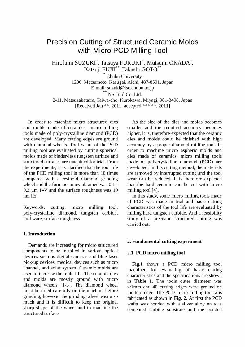
Fig.1 shows a PCD micro milling tool machined for evaluating of basic cutting characteristics and the specifications are shown in Table 1. The tools outer diameter was Φ1mm and 40 cutting edges were ground on the tool edge. The PCD micro milling tool was fabricated as shown in Fig. 2. At first the PCD wafer was bonded with a silver alloy on to a cemented carbide substrate and the bonded
PCD plate was cut to small cylindrical chips by wire EDM. The PCD chip was bonded on to a cemented carbide shank with a silver alloy. Finally, the end face and side face of the PCD chip was ground by a diamond wheel, and the cutting edges were ground by a sharp diamond wheel. (a) A view (b) SEM photograph Fig. 1 Photographs of PCD micro milling tool Table 1 Specifications of milling tool
Fig. 2 Machining process of PCD micro milling tool
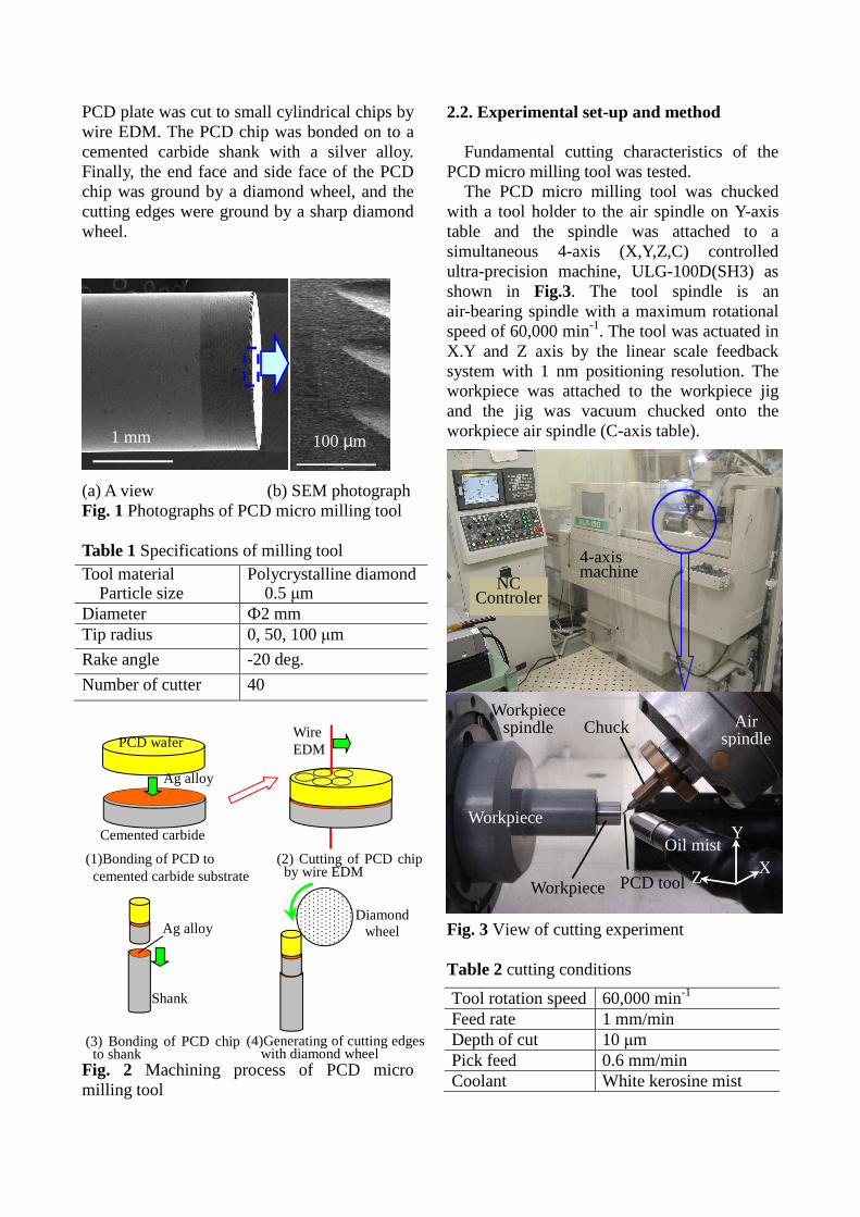
2.2. Experimental set-up and method Fundamental cutting characteristics of the PCD micro milling tool was tested.
The PCD micro milling tool was chucked with a tool holder to the air spindle on Y-axis table and the spindle was attached to a simultaneous 4-axis (X,Y,Z,C) controlled ultra-precision machine, ULG-100D(SH3) as shown in Fig.3. The tool spindle is an air-bearing spindle with a maximum rotational speed of 60,000 min-1. The tool was actuated in X.Y and Z axis by the linear scale feedback system with 1 nm positioning resolution. The workpiece was attached to the workpiece jig and the jig was vacuum chucked onto the workpiece air spindle (C-axis table). Fig. 3 View of cutting experiment Table 2 cutting conditions
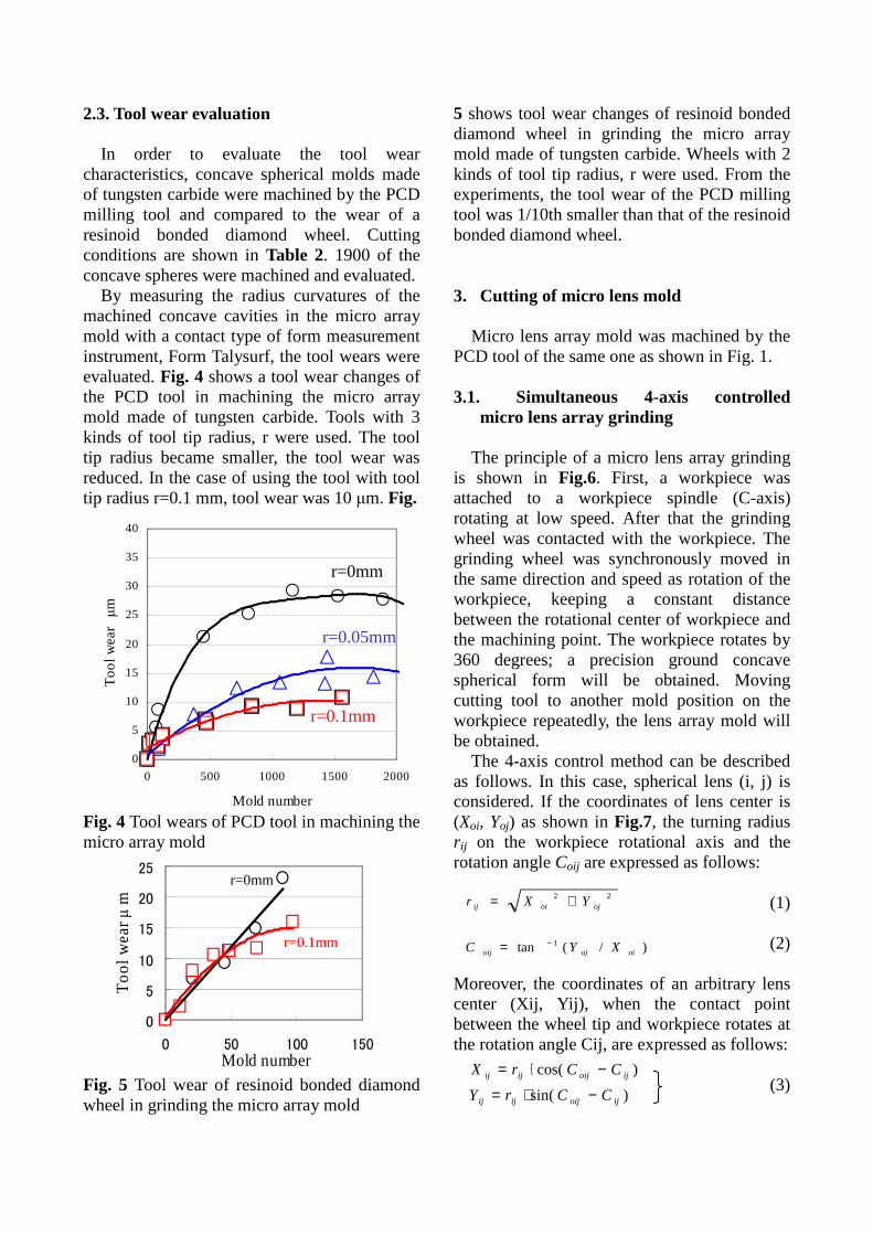
In order to evaluate the tool wear characteristics, concave spherical molds made of tungsten carbide were machined by the PCD milling tool and compared to the wear of a resinoid bonded diamond wheel. Cutting conditions are shown in Table 2. 1900 of the concave spheres were machined and evaluated. By measuring the radius curvatures of the machined concave cavities in the micro array mold with a contact type of form measurement instrument, Form Talysurf, the tool wears were evaluated. Fig. 4 shows a tool wear changes of the PCD tool in machining the micro array mold made of tungsten carbide. Tools with 3 kinds of tool tip radius, r were used. The tool tip radius became smaller, the tool wear was reduced. In the case of using the tool with tool tip radius r=0.1 mm, tool wear was 10 µm. Fig. Fig. 4 Tool wears of PCD tool in machining the micro array mold Fig. 5 Tool wear of resinoid bonded diamond wheel in grinding the micro array mold
5 shows tool wear changes of resinoid bonded diamond wheel in grinding the micro array mold made of tungsten carbide. Wheels with 2 kinds of tool tip radius, r were used. From the experiments, the tool wear of the PCD milling tool was 1/10th smaller than that of the resinoid bonded diamond wheel. 3. Cutting of micro lens mold
Micro lens array mold was machined by the PCD tool of the same one as shown in Fig. 1. 3.1. Simultaneous 4-axis controlled
micro lens array grinding
The principle of a micro lens array grinding is shown in Fig.6. First, a workpiece was attached to a workpiece spindle (C-axis) rotating at low speed. After that the grinding wheel was contacted with the workpiece. The grinding wheel was synchronously moved in the same direction and speed as rotation of the workpiece, keeping a constant distance between the rotational center of workpiece and the machining point. The workpiece rotates by 360 degrees; a precision ground concave spherical form will be obtained. Moving cutting tool to another mold position on the workpiece repeatedly, the lens array mold will be obtained.
The 4-axis control method can be described as follows. In this case, spherical lens (i, j) is considered. If the coordinates of lens center is (Xoi, Yoj) as shown in Fig.7, the turning radius r ij on the workpiece rotational axis and the rotation angle Coij are expressed as follows:
(1)
(2) Moreover, the coordinates of an arbitrary lens center (Xij, Yij), when the contact point between the wheel tip and workpiece rotates at the rotation angle Cij, are expressed as follows:
(3)
0
5
10
15
20
25
30
35
40
0 500 1000 1500 2000
Mold number
To
ol w
ea
r µm
r=0.05mm
r=0mm
r=0.1mm
0
5
10
15
20
25
0 50 100 150Mold number
To
ol w
ea
r µ m
r=0.1mm
r=0mm
)/(tan 1
22
oiojoij
ojoiij
XYC
YXr
−=
+=
)sin(
)cos(
ijoijijij
ijoijijij
CCrY
CCrX
−⋅=
−⋅=
0.000
0.005
0.010
0.015
0.020
0.025
0.030
0 1000 2000
Su
rfac
e ro
ugh
nes
s µm R
z
Mold number
PCD, R0 mm
Therefore, grinding wheel is controlled in 4-axis (X, Y, Z, C) simultaneously with grinding in Z direction by using of Eqs. (1)-(3). Fig. 6 Principle of micro lens array cutting (a) First position (b) After rotation Fig. 7 Calculation of tool path in micro lens array cutting 3.2. Surface roughness of the machined lens array mold
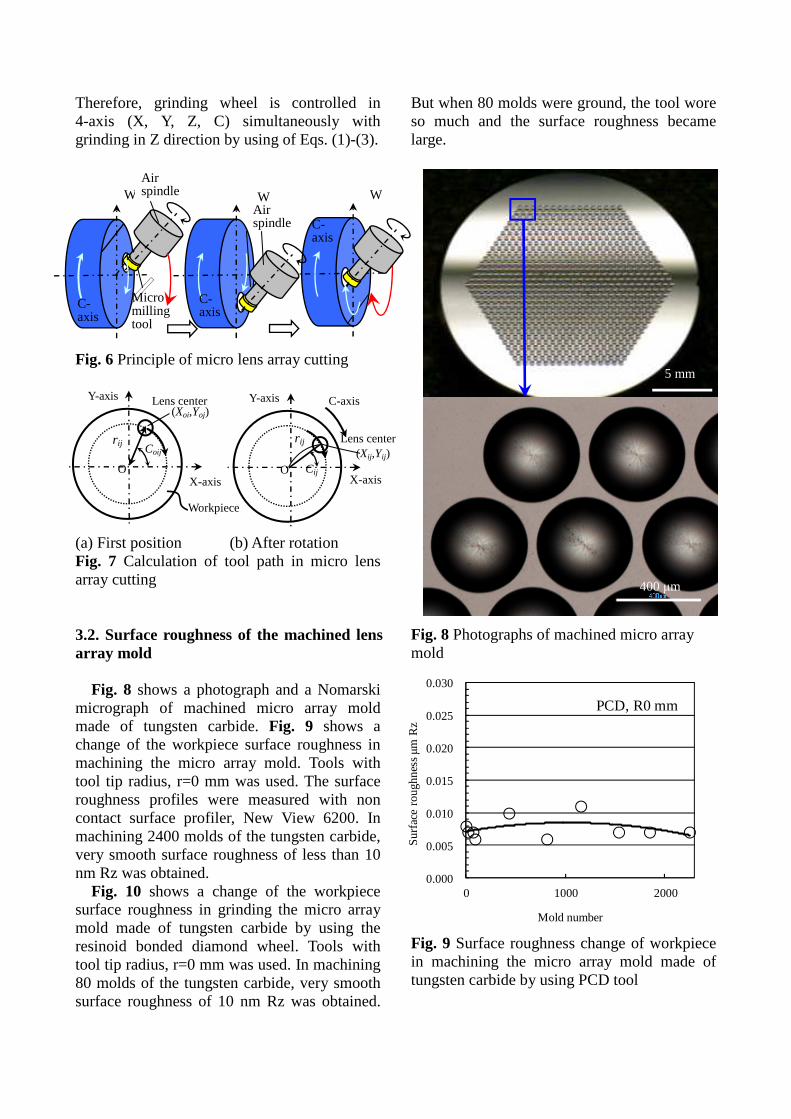
Fig. 8 shows a photograph and a Nomarski micrograph of machined micro array mold made of tungsten carbide. Fig. 9 shows a change of the workpiece surface roughness in machining the micro array mold. Tools with tool tip radius, r=0 mm was used. The surface roughness profiles were measured with non contact surface profiler, New View 6200. In machining 2400 molds of the tungsten carbide, very smooth surface roughness of less than 10 nm Rz was obtained.
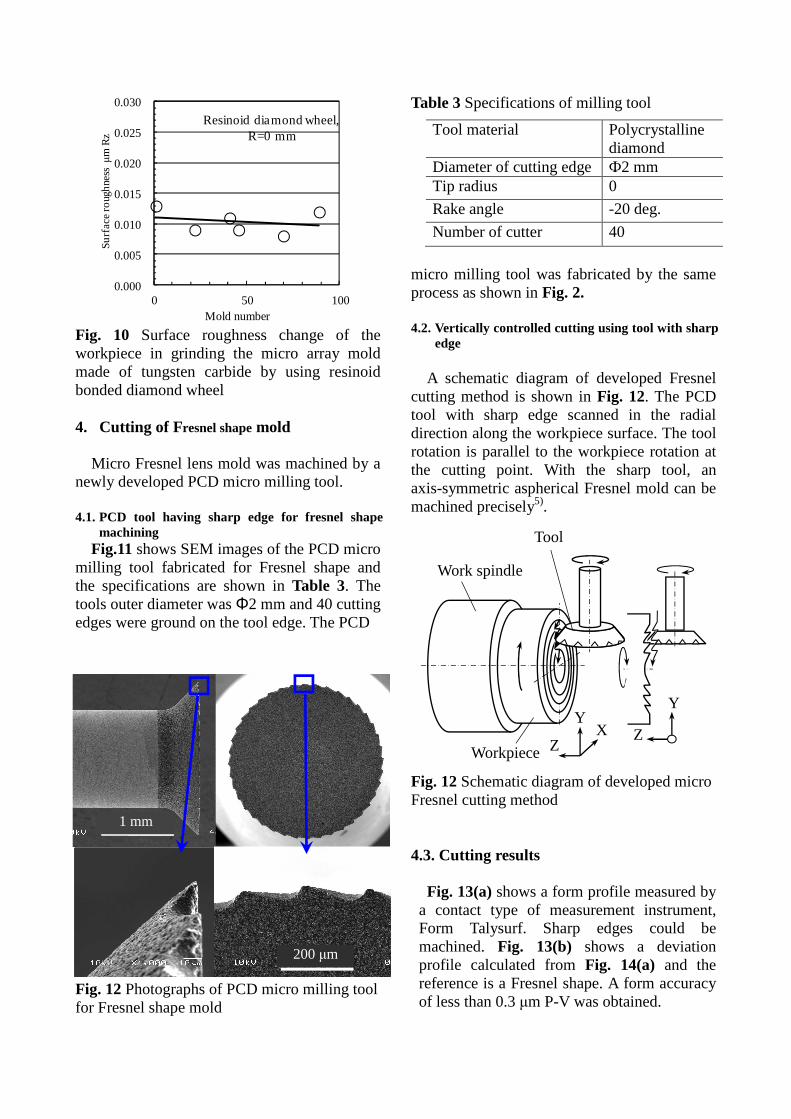
Fig. 10 shows a change of the workpiece surface roughness in grinding the micro array mold made of tungsten carbide by using the resinoid bonded diamond wheel. Tools with tool tip radius, r=0 mm was used. In machining 80 molds of the tungsten carbide, very smooth surface roughness of 10 nm Rz was obtained.
But when 80 molds were ground, the tool wore so much and the surface roughness became large. Fig. 8 Photographs of machined micro array mold Fig. 9 Surface roughness change of workpiece in machining the micro array mold made of tungsten carbide by using PCD tool
C- axis
Micro milling tool
Air spindle W
orC- axis
C- axis
Wor
WAir spindle
X-axis
Y-axis
Coij r ij
(Xoi,Yoj)
Workpiece
Lens center
O (Xij,Yij)
Cij
r ij
C-axis
Lens center
O X-axis
Y-axis
400 µm
5 mm
0.000
0.005
0.010
0.015
0.020
0.025
0.030
0 50 100
Su
rfa
ce ro
ugh
ness
µ
m R
z
Mold number
Resinoid diamond wheel,R=0 mm
Fig. 10 Surface roughness change of the workpiece in grinding the micro array mold made of tungsten carbide by using resinoid bonded diamond wheel 4. Cutting of F resnel shape mold
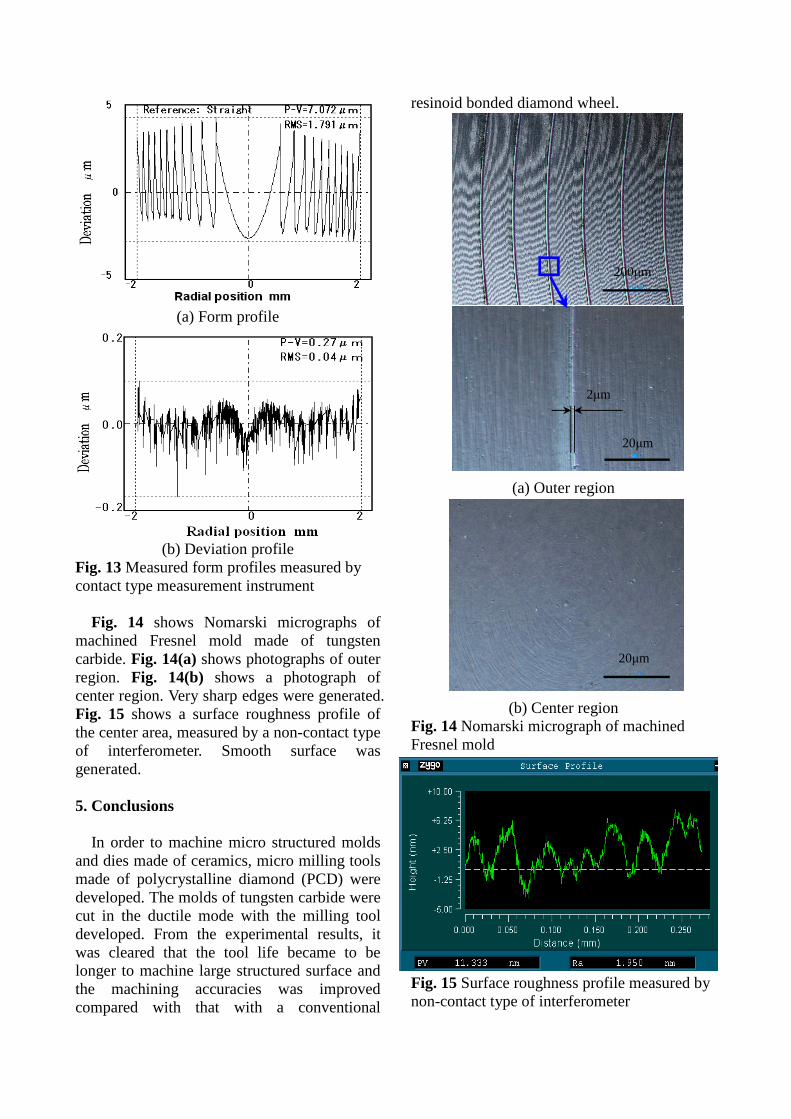
Micro Fresnel lens mold was machined by a newly developed PCD micro milling tool. 4.1. PCD tool having sharp edge for fresnel shape
machining Fig.11 shows SEM images of the PCD micro
milling tool fabricated for Fresnel shape and the specifications are shown in Table 3. The tools outer diameter was Φ2 mm and 40 cutting edges were ground on the tool edge. The PCD Fig. 12 Photographs of PCD micro milling tool for Fresnel shape mold
Table 3 Specifications of milling tool
micro milling tool was fabricated by the same process as shown in Fig. 2. 4.2. Vertically controlled cutting using tool with sharp
edge
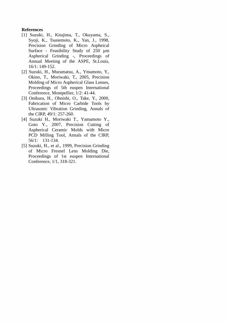
A schematic diagram of developed Fresnel cutting method is shown in Fig. 12. The PCD tool with sharp edge scanned in the radial direction along the workpiece surface. The tool rotation is parallel to the workpiece rotation at the cutting point. With the sharp tool, an axis-symmetric aspherical Fresnel mold can be machined precisely5). Fig. 12 Schematic diagram of developed micro Fresnel cutting method 4.3. Cutting results
Fig. 13(a) shows a form profile measured by a contact type of measurement instrument, Form Talysurf. Sharp edges could be machined. Fig. 13(b) shows a deviation profile calculated from Fig. 14(a) and the reference is a Fresnel shape. A form accuracy of less than 0.3 µm P-V was obtained.
Tool material Polycrystalline diamond
Diameter of cutting edge Ф2 mm Tip radius 0
Rake angle -20 deg.
Number of cutter 40
1 mm
200 µm
Workpiece
X Y
Z
Work spindle
Tool
Y
Z
(a) Form profile
(b) Deviation profile Fig. 13 Measured form profiles measured by contact type measurement instrument
Fig. 14 shows Nomarski micrographs of machined Fresnel mold made of tungsten carbide. Fig. 14(a) shows photographs of outer region. Fig. 14(b) shows a photograph of center region. Very sharp edges were generated. Fig. 15 shows a surface roughness profile of the center area, measured by a non-contact type of interferometer. Smooth surface was generated. 5. Conclusions
In order to machine micro structured molds and dies made of ceramics, micro milling tools made of polycrystalline diamond (PCD) were developed. The molds of tungsten carbide were cut in the ductile mode with the milling tool developed. From the experimental results, it was cleared that the tool life became to be longer to machine large structured surface and the machining accuracies was improved compared with that with a conventional
resinoid bonded diamond wheel.
(a) Outer region
(b) Center region Fig. 14 Nomarski micrograph of machined Fresnel mold Fig. 15 Surface roughness profile measured by non-contact type of interferometer
Syoji, K., Tsunemoto, K., Yan, J., 1998, Precision Grinding of Micro Aspheical Surface - Feasibility Study of 250 µm Aspherical Grinding -, Proceedings of Annual Meeting of the ASPE, St.Louis, 16/1: 149-152.
[2] Suzuki, H., Muramatsu, A., Ymamoto, Y., Okino, T., Moriwaki, T., 2005, Precision Molding of Micro Aspherical Glass Lenses, Proceedings of 5th euspen International Conference, Montpellier, 1/2: 41-44.
[3] Onikura, H., Ohnishi, O., Take, Y., 2000, Fabrication of Micro Carbide Tools by Ultrasonic Vibration Grinding, Annals of the CIRP, 49/1: 257-260.
[4] Suzuki H., Moriwaki T., Yamamoto Y., Goto Y., 2007, Precision Cutting of Aspherical Ceramic Molds with Micro PCD Milling Tool, Annals of the CIRP, 56/1: 131-134.
[5] Suzuki, H., et al., 1999, Precision Grinding of Micro Fresnel Lens Molding Die, Proceedings of 1st euspen International Conference, 1/1, 318-321.