104
Precision Linear Actuators www.danahermotion.com Precision Linear Actuators
Precision Linear Actuators
�www.danahermotion.com
Precision Linear Actuators

� www.danahermotion.com
Danaher Motion - Helping you build a better machine, faster Danaher Corporation combined over 30 industry-leading brands such as Kollmorgen, Thomson, Dover, Pacific Scientific, Portescap, Neff, Seidel and Bautz to establish a customer-focused motion control manufacturing company called Danaher Motion. We offer this powerful set of integrated motion control technologies under the Danaher Motion and Thomson brand names. We are a $�B+ global motion control leader, unique in our ability to marshal decades of application experi-ence and technical innovation to help you build better machines, faster.
Danaher Motion defines high standards of quality, innovation and technology. We enable improved machine performance and reliability while controlling costs. Our global manufacturing footprint, rapid customization and prototyping capa-bilities drive quick lead times. Unmatched application experience and design expertise empowers you to commission machines faster.
Consider your options in today’s market for a motion control partner. Select Danaher Motion and join a team with 6�00 employees, over 60 years of application experience and �000+ distributor locations around the globe. Danaher Motion serves industries as diverse as semiconductor, aerospace and defense, electric vehicle systems, packaging, printing, medical and robotics. We offer an unparalleled depth and breadth of motion control product solutions through a world-wide service and support infrastructure, field service engineers and support teams available when and where you need them.
The Danaher Business System - Building sustainable competitive advantage into your business
The Danaher Business System (DBS) was established to increase the value we bring to customers. It is a mature and successful set of tools we use daily to continually improve manufacturing operations and product development pro-cesses. DBS is based on the principles of Kaizen which continuously and aggressively eliminate waste in every aspect of our business. DBS focuses the entire organization on achieving breakthrough results that create competitive advan-tages in quality, delivery and performance – advantages that are passed on to you. Through these advantages Danaher Motion is able to provide you faster times to market as well as unsurpassed product selection, service, reliability and productivity.
Local Support Around the Globe
Application Centers Global Design & Engineering CentersGlobal Manufacturing Operations

Precision Linear Actuators
3www.danahermotion.com
Introduction ...........................................................................................3 Company Introduction ..................................................................... 4 Product Introduction ........................................................................ 5 Applications .......................................................................................6 The Benefits of Electrification .........................................................7 Performance Overview........................................................................8 Precision Linear Actuator Range ..............................................8 - 9 EC Series ..............................................................................................�0 Introduction ......................................................................................10 Overview ...........................................................................................11 EC2 - Acme screw, Parallel 24 Volt DC Motor .....................12 - 13 EC2 - Acme screw, Inline 24 Volt DC Motor .........................14 - 15 EC2 - Ball screw, Parallel 24 Volt DC Motor .........................16 - 17 EC2 - Ball screw, Inline 24 Volt DC Motor.............................18 - 19 EC2 - Ball screw, Parallel BK23 AC Servo Motor ................20 - 21 EC2 - Ball screw, Inline BK23 AC Servo Motor ....................22 - 23 EC3 - Ball screw, Parallel BK23 AC Servo Motor ................24 - 25 EC3 - Ball screw, Parallel BK32 AC Servo Motor ................26 - 27 EC3 - Ball screw, Inline BK23 or BK32 AC Servo Motor .....28 - 29 EC4 - Ball screw, Parallel BK32 AC Servo Motor ................30 - 31 EC4 - Ball screw, Inline BK32 AC Servo Motor ....................32 - 33 EC5 - Ball screw, Parallel BK32 AC Servo Motor ................34 - 35 EC5 - Ball screw, Parallel BK42 AC Servo Motor ................36 - 37 EC5 - Ball screw, Inline BK32 or BK42 AC Servo Motor .....38 - 39 Mounting Options .....................................................................40 - 43 Adapter Options ........................................................................44 - 45 Other Options ...................................................................................46 Accessories .....................................................................................47
ECT Series ............................................................................................48 Introduction ......................................................................................48 Overview ...........................................................................................49 ECT90 - Parallel IEC90 AC motor ............................................50 - 51 ECT90 - Parallel B43 AC Servo Motor ...................................52 - 53 ECT90 - Parallel B53 AC Servo Motor ...................................54 - 55 ECT90 - Direct Drive, Inline B43 AC Servo Motor ...............56 - 57 ECT90 - Direct Drive, Inline B53 AC Servo Motor ...............58 - 59 ECT90 - Planetary Gear, Inline B43 AC Servo Motor ............60 - 61 ECT90 - Planetary Gear, Inline B53 AC Servo Motor ............62 - 63 ECT130 - Parallel IEC100 AC Motor .......................................64 - 65 ECT130 - Parallel B53 AC Servo Motor .................................66 - 67 ECT130 - Parallel B63 AC Servo Motor .................................68 - 69 ECT130 - Direct Drive, Inline B53 AC Servo Motor .............70 - 71 ECT130 - Direct Drive, Inline B63 AC Servo Motor .............72 - 73 ECT130 - Planetary Gear, Inline B53 AC Servo Motor .............74 - 75 ECT130 - Planetary Gear, Inline B63 AC Servo Motor .............76 - 77 Mounting Options .....................................................................78 - 79 Adapter Options ........................................................................80 - 83 Sensors Option ................................................................................84 Protection Option ............................................................................85
IntroductionTable of Contents
Ordering Keys ......................................................................................86 EC2 ..............................................................................................86 - 88 EC3 .....................................................................................................89 EC4 .....................................................................................................90 EC5 .....................................................................................................91 ECT90 ..........................................................................................92 - 93 ECT130 ........................................................................................94 - 95
Glossary................................................................................................96 A - Bra ...............................................................................................96 Bre - C ...............................................................................................97 D - Fo .................................................................................................98 Fr - L ...................................................................................................99 M - Po ..............................................................................................100 Pr -Sp ...............................................................................................101 St - T ................................................................................................102
Application Data Form .....................................................................�03 Worksheet ......................................................................................103

4 www.danahermotion.com
Danaher Motion is one of the leading suppliers of motion control products in the world offering a complete product portfolio. Actuators, servo motors, lead screws, servo drives and controls are just some of the products manufactured by Danaher Motion. The precision linear actuator range is a result of over 40 years of actuator development and represents the state of the art in linear actuator design.
The precision linear actuators in this catalog represent the experience gained during decades of actuator development. The result are design concepts that will work in the hardest applications imaginable and unique product features unavailable anywhere else.
World wide representationDanaher Motion has plants, support centers and sales offices all around the globe. In addition we have a large network of distributors and system houses that all are ready to support you throughout the entire life cycle of the product.
Danaher Motion - a complete supplier Danaher Motion develop, produce and sell motion control products of all types. If you need a servo drive, a
programmable control or a linear guide that match your precision linear actuator you can be sure that Danaher Motion has the ideal choice for your application. Please visit www.danahermotion.com for more information on us and our products.
Online product selector toolSelection is made easy when using our precision linear actuator product selector at www.danahermotion.com/PLA_advisor. This online tool helps you select the right system for your application needs based off pre-selected performance and electromechanical criteria.
IntroductionCompany Introduction

Precision Linear Actuators
�www.danahermotion.com
IntroductionProduct Introduction
Danaher Motion offers two high performance precision linear actuator series - the black EC series in four sizes and the aluminum-colored ECT series in two sizes. Both series are ideal for positioning loads that are either externally-guided and supported, or pivoting. They are also ideal where there is a high concentration of airborne contaminants, as rodless actuators are inherently less well protected.
Strong, fast and accurateThe hallmark for the entire range of precision linear actuators is the ability to work hard, fast and accurately, day in and day out, under the toughest conditions.
Hydraulics and pneumatics replacementPrecision linear actuators are direct descendants of hydraulic and pneumatic cylinders. Possessing many of the same unique design characteristics that made hydraulic and pneumatic cylinders popular, actuators benefit from cleaner, simpler and more energy-efficient power transmission. They are also much easier to integrate with modern programmable controls, have greater accuracy and are less noisy.
Harsh environmentsChemical plants, paper mills, welding operations and outdoor applications are all suitable for precision linear actuators. IP65 protection as standard or as option, a robust design and the use of high-quality components makes them suitable for almost every location.
Minimum maintenanceAll precision linear actuators are designed to require a minimum of maintenance. There are no parts that need to be replaced due to wear. Regular lubrication is needed only in applications where the actuator works hard and frequently.
Customized unitsCustomization is one of our strengths and we have built hundreds of customized units. If you need a special stroke, a unique mounting bracket, or some other adaptation of the standard product, our engineers will help you find the perfect solution for your application. Please contact customer service for more information.
Precision linear actuators can successfully be used in handling, machining and manufacturing applications. Another suitable area is in the replacement of hydraulic or pneumatic cylinders where they bring many benefits compared to these traditional technologies. The broad range of options and accessories and our long experience in building customized units makes it easy to find the perfect actuator for almost any application.

6 www.danahermotion.com
Precision linear actuators can fit a wide variety of applications within many motion industries. In combination with high performance drives and controls from Danaher Motion, design into linear motion equipment is made easy and simple. Some common applications are described below.
IntroductionApplications
Valve Control• Process industry• Ventilation equipment• Vehicle applications• Packaging industry
Edge Guide Control• Paper mills• Print shop equipment• Textile industry
Drilling, Welding, Gluing or Thermo-forming• Machine tools• Plastic industry• Metal industry• Wood work industry• Electronic industry• Packaging industry
Backstop Adjust• Wood work industry • Machine tools• Metal industry
Linear Guide Positioning• Machine tools• Vehicle applications• Electronic industry• Scanning equipment• Supervision equipment
Loading or Unloading • Handling equipment• Packaging industry• Medical industry• Electronic industry

Precision Linear Actuators
�www.danahermotion.com
Precision linear actuators are often a better choice than hydraulic or pneumatic alternatives with advantages of simpler and smaller installation, easier control, lower energy costs, higher accuracy, less maintenance, less noise, and a cleaner, healthier environment.
IntroductionThe Benefits of Electrification
Electrical Actuators vs. Hydraulic and Pneumatic CylindersElectrical Linear Actuators Hydraulic Cylinders Pneumatic Cylinders
Installation All electric operation requiressimple wiring.
Requires expensive plumbing,filtering, pumps, etc.
Requires expensive plumbing,filtering, pumps, etc.
Accuracy Very repeatable (to ± 0,013 mm) and rigid, multi-stop capabilities.
Requires expensive positionsensing and precise electro-hydraulic valving to implement, has tendency to creep.
Difficult to achieve.Requires expensive position sensing and precise valving to implement, has tendency to creep.
Control Directly compatible with standard programmable controls allowing easy automatic operation of complex motion sequences.
Requires electronic/fluidinterfaces and exotic valve designs. Hysteresis, dead zone, supply pressure and temperature changes complicate control.
Inherently non-linear,compressible power sourceseverely complicates servocontrol.
Speed Smooth, variable speed with from 0 to 2 m/s with controlled accleration.
Difficult to control accurately.Varies with temperature and wear. Stick slip can be a problem.
More susceptible to stick slip and varying load. Well-suited for light high speed applications.
Reliability Repeatable, reproducibleperformance during the entire product life. Very little maintenance required.
Very contamination sensitive.Require regular maintenance. Seals are prone to leak. Reliable with diligent maintenance.
Very contamination sensitive. Air sources require proper filtration. Good reliability, but usually many system components are involved.
Power Up to 40 000 N Virtually unlimited force. Mostpowerful.
Up to 25 000 N. Typically usedbelow 6000 N.
Life expectancy Up to millions of cycles at ratedload. Easy to predict.
Dependent on design and sealwear, usually good.
Dependent on design and sealwear, usually good.
Environment Standard models rated for -30 to +70 °C. Inherently clean and energy efficient.
Temperature extremes can bea major problem. Seals areprone to leak. Waste disposalis increasingly problematic.
Temperature extremes can be a major problem. Seals prone to leak. Air-borne oil can be aproblem.
Load holding Acme screw units are selflockingif power fails. Fail-safe brakes available for ball screw models.
Complex back-up safety devices must be used.
Complex back-up safety devices must be used.
Cost Moderate initial cost, very lowoperating cost.
Components often cost less, but installation and maintenance are increased. Hydraulic power unit cost is high if not pre-existing.
Components often cost less, but installation and maintenance are increased.

8 www.danahermotion.com
EC� EC3 EC4 EC� ECT90 EC T�30
Performance OverviewPrecision Linear Actuator Range
Load
Maximum load, Fx [N] 3600 7200 12000 25000 20000 38000
Maximum load, Fy [N] 0 0 0 0 500 800
Maximum load, Fz [N] 0 0 0 0 500 800
Maximum load torque, Mx [Nm] 5 7,5 10 10 - -
Maximum load torque, My [Nm] 0 0 0 0 150 300
Maximum load torque, Mz [Nm] 0 0 0 0 150 300
Stroke
Maximum standard stroke [mm] 750 1000 1500 1500 1500 2000
Speed
Maximum speed [m/s] 1,28 1,28 1,33 1,33 1,6 2,0
Accuracy
Repeatability [± mm] 0,013 0,013 0,013 0,013 0,05 0,05
Backlash - acme / ball screw [mm] 0,4 / 0,25 0,4 / 0,25 / 0,25 / 0,3 / 0,11 (0,18) 1 / 0,21
General data
Profile size (width × height) [mm] 55 × 55 68 × 68 94 × 94 94 × 94 90 × 92 130 × 130
Operating temperature limits [°C] 0 – +70 0 – +70 0 – +70 0 – +70 -20 – +70 -20 – +70
Maximum duty cycle [%] 100 100 100 100 100 100
Lead screw diameter [mm] 16 16, 20 25 32 25, 32 40
Lead screw type acme or ball screw ball screw ball screw ball screw ball screw ball screw
Protection class - standard / optional IP54 / IP65 IP54 / IP65 IP54 / IP65 IP54 / IP65 IP65 IP65
Features
DC motor / Brushless AC servo motor / Three phase AC motor • / • / / • / / • / / • / / • / • / • / •
Single point lubrication • • • • •
Mounting options
Magnetic position sensors • • • • • •
Mounting feet kit • • • • • •
Trunnion mounting kit • • • • • •
Clevis mounting kit • • • • • •
Front / rear flange mounting kit • • • •
Tube end - inside thread / outside thread / clevis / spherical joint • / • / • / • • / • / • / • • / • / • / • • / • / • / • • / • / / • / • / / 1 Depending on the screw diameter used in the actuator.

Precision Linear Actuators
9www.danahermotion.com
EC� EC3 EC4 EC� ECT90 EC T�30
Load
Maximum load, Fx [N] 3600 7200 12000 25000 20000 38000
Maximum load, Fy [N] 0 0 0 0 500 800
Maximum load, Fz [N] 0 0 0 0 500 800
Maximum load torque, Mx [Nm] 5 7,5 10 10 - -
Maximum load torque, My [Nm] 0 0 0 0 150 300
Maximum load torque, Mz [Nm] 0 0 0 0 150 300
Stroke
Maximum standard stroke [mm] 750 1000 1500 1500 1500 2000
Speed
Maximum speed [m/s] 1,28 1,28 1,33 1,33 1,6 2,0
Accuracy
Repeatability [± mm] 0,013 0,013 0,013 0,013 0,05 0,05
Backlash - acme / ball screw [mm] 0,4 / 0,25 0,4 / 0,25 / 0,25 / 0,3 / 0,11 (0,18) 1 / 0,21
General data
Profile size (width × height) [mm] 55 × 55 68 × 68 94 × 94 94 × 94 90 × 92 130 × 130
Operating temperature limits [°C] 0 – +70 0 – +70 0 – +70 0 – +70 -20 – +70 -20 – +70
Maximum duty cycle [%] 100 100 100 100 100 100
Lead screw diameter [mm] 16 16, 20 25 32 25, 32 40
Lead screw type acme or ball screw ball screw ball screw ball screw ball screw ball screw
Protection class - standard / optional IP54 / IP65 IP54 / IP65 IP54 / IP65 IP54 / IP65 IP65 IP65
Features
DC motor / Brushless AC servo motor / Three phase AC motor • / • / / • / / • / / • / / • / • / • / •
Single point lubrication • • • • •
Mounting options
Magnetic position sensors • • • • • •
Mounting feet kit • • • • • •
Trunnion mounting kit • • • • • •
Clevis mounting kit • • • • • •
Front / rear flange mounting kit • • • •
Tube end - inside thread / outside thread / clevis / spherical joint • / • / • / • • / • / • / • • / • / • / • • / • / • / • • / • / / • / • / /

�0 www.danahermotion.com
EC SeriesIntroduction
The proven design of the EC actuators has found its way into thousands of applications throughout the world. Regardless of the environment or requirement, we can customize our standard models to fit just about any application. The EC series combines durability and ease-of-use with the largest selection of factory-engineered options available today.

Precision Linear Actuators
��www.danahermotion.com
Parameter EC� EC3
Profile size (width × height) [mm] 55 × 55 68 × 68
Stroke length (S), maximum [mm] 700 1000
Speed, maximum [m/s] 1,28 1,28
Load (Fx), maximum [N] 3600 7200
Available motor types DC motor or AC servo motor AC servo motor
Page
Features• Extruded anodized aluminum cover tube• Anodized aluminum housing• Stainless steel extension tube• Acme or ball screw drive• Permanent magnet DC motor or brushless AC servo motor• Parallel or Inline motor• Maintenance free• Belt gear, helical spur gear or direct drive• Large range of options and accessories
EC SeriesOverview
Parameter EC4 EC�
Profile size (width × height) [mm] 94 × 94 94 × 94
Stroke length (S), maximum [mm] 1500 1500
Speed, maximum [m/s] 1,33 1,33
Load (Fx), maximum [N] 12000 25000
Available motor types AC servo motor AC servo motor
Page
Definition of Forces
�� www.danahermotion.com
Standard Features and Benefits
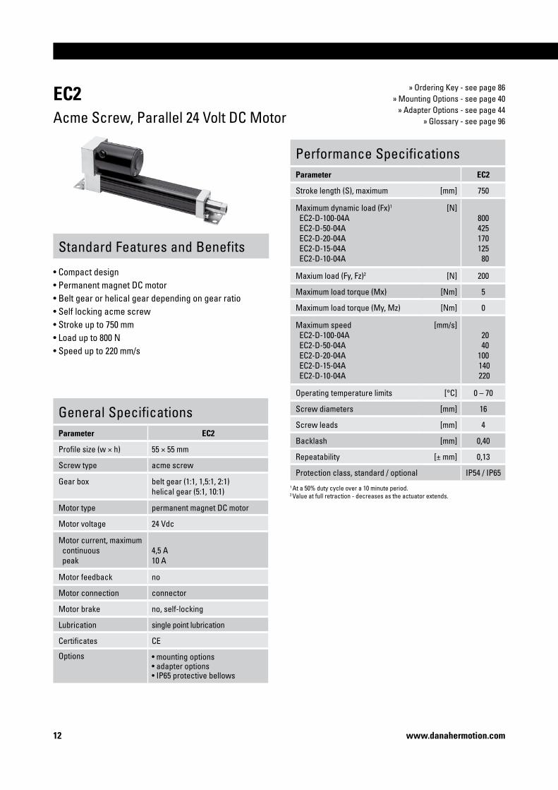
EC�Acme Screw, Parallel 24 Volt DC Motor
• Compact design • Permanent magnet DC motor• Belt gear or helical gear depending on gear ratio• Self locking acme screw• Stroke up to 750 mm• Load up to 800 N• Speed up to 220 mm/s
Performance SpecificationsParameter EC�
Stroke length (S), maximum [mm] 750
Maximum dynamic load (Fx)1
EC2-D-100-04A EC2-D-50-04A EC2-D-20-04A EC2-D-15-04A EC2-D-10-04A
[N]800425170125 80
Maxium load (Fy, Fz)2 [N] 200
Maximum load torque (Mx) [Nm] 5
Maximum load torque (My, Mz) [Nm] 0
Maximum speed EC2-D-100-04A EC2-D-50-04A EC2-D-20-04A EC2-D-15-04A EC2-D-10-04A
[mm/s] 20 40100 140 220
Operating temperature limits [°C] 0 – 70
Screw diameters [mm] 16
Screw leads [mm] 4
Backlash [mm] 0,40
Repeatability [± mm] 0,13
Protection class, standard / optional IP54 / IP65
» Ordering Key - see page 86» Mounting Options - see page 40
» Adapter Options - see page 44» Glossary - see page 96
General SpecificationsParameter EC�
Profile size (w × h) 55 × 55 mm
Screw type acme screw
Gear box belt gear (1:1, 1,5:1, 2:1)helical gear (5:1, 10:1)
Motor type permanent magnet DC motor
Motor voltage 24 Vdc
Motor current, maximum continuous peak
4,5 A10 A
Motor feedback no
Motor connection connector
Motor brake no, self-locking
Lubrication single point lubrication
Certificates CE
Options • mounting options• adapter options• IP65 protective bellows
1 At a 50% duty cycle over a 10 minute period. 2 Value at full retraction - decreases as the actuator extends.

Precision Linear Actuators
�3www.danahermotion.com
S max: maximum stroke (ordering stroke in mm) T: top sideL: cover tube length R: right sideL tot: retracted length L: left side
EC�Acme Screw, Parallel 24 Volt DC Motor
Retracted length (L tot) [mm] L tot = S max + 243,4
Weight of unit [kg] kg = 4,28 + 0,006 + S max
Performance Diagrams
V: speed F: load
1: EC2-D-100-04A2: EC2-D-50-04A3: EC2-D-20-04A
A1: breather tube output cover, 1/8 NPT - 11,1 HEX
Critical Speed vs. Stroke
Column Load Limit vs. Stroke
v: speed S: stroke length
1: EC2-D- • • -04A
F: load S: stroke length
1: EC2-D- • • -04A
= Performance at a duty cycle of maximum 50%. = Performance at a duty cycle of maximum 30%.
Speed vs. Load
4: EC2-D-15-04A5: EC2-D-10-04A

�4 www.danahermotion.com
Standard Features and Benefits
EC�Acme Screw, Inline 24 Volt DC Motor
• Compact design • Permanent magnet DC motor• Direct drive• Self locking acme screw• Stroke up to 750 mm• Load up to 80 N• Speed up to 220 mm/s
» Ordering Key - see page 86» Mounting Options - see page 40
» Adapter Options - see page 44» Glossary - see page 96
Performance SpecificationsParameter EC�
Stroke length (S), maximum [mm] 750
Maximum dynamic load (Fx)1
EC2-D-10L-04A [N]
80
Maxium load (Fy, Fz)2 [N] 200
Maximum load torque (Mx) [Nm] 5
Maximum load torque (My, Mz) [Nm] 0
Maximum speed EC2-D-10L-04A
[mm/s]220
Operating temperature limits [°C] 0 – 70
Screw diameters [mm] 16
Screw leads [mm] 4
Backlash [mm] 0,40
Repeatability [± mm] 0,13
Length of motor leads [mm] 150
Protection class, standard / optional IP54 / IP65General SpecificationsParameter EC�
Profile size (w × h) 55 × 55 mm
Screw type acme screw
Gear box no, direct drive
Motor type permanent magnet DC motor
Motor voltage 24 Vdc
Motor current, maximum continuous peak
4,5 A10 A
Motor feedback no
Motor connection flying leads
Motor brake no, self-locking
Lubrication single point lubrication
Certificates CE
Options • mounting options• adapter options• IP65 protective bellows
1 At a 50% duty cycle over a 10 minute period. 2 Value at full retraction - decreases as the actuator extends.

Precision Linear Actuators
��www.danahermotion.com
EC�Acme Screw, Inline 24 Volt DC Motor
Retracted length (L tot) [mm] L tot = S max + 255,5
Weight of unit [kg] kg = 4,28 + 0,006 + S max
Performance Diagrams
S max: maximum stroke (ordering stroke in mm) T: top sideL: cover tube length R: right sideL tot: retracted length L: left side
A1: breather tube output cover, 1/8 NPT - 11,1 HEX
Critical Speed vs. Stroke
Column Load Limit vs. Stroke
v: speed S: stroke length
1: EC2-D-10L-04A
F: load S: stroke length
1: EC2-D-10L-04A
V: speed F: load
1: EC2-D-10L-04A
= Performance at a duty cycle of maximum 50%. = Performance at a duty cycle of maximum 30%.
Speed vs. Load

�6 www.danahermotion.com
EC�Ball Screw, Parallel 24 Volt DC Motor
» Ordering Key - see page 87» Mounting Options - see page 40
» Adapter Options - see page 44» Glossary - see page 96
Standard Features and Benefits
• Compact design • Permanent magnet DC motor• Belt gear or helical gear depending on gear ratio• Ball screw• Stroke up to 750 mm• Load up to 1330 N• Speed up to 820 mm/s
Performance SpecificationsParameter EC�
Stroke length (S), maximum [mm] 750
Maximum dynamic load (Fx)1
EC2-D-100-05B EC2-D-50-05B EC2-D-100-16B EC2-D-20-05B EC2-D-50-16B EC2-D-15-05B EC2-D-10-05B EC2-D-20-16B EC2-D-15-16B EC2-D-10-16B
[N]1330 670 420 280 200 200 140 80 60 40
Maxium load (Fy, Fz)2 [N] 200
Maximum load torque (Mx) [Nm] 5
Maximum load torque (My, Mz) [Nm] 0
Maximum speed EC2-D-100-05B EC2-D-50-05B EC2-D-100-16B EC2-D-20-05B EC2-D-50-16B EC2-D-15-05B EC2-D-10-05B EC2-D-20-16B EC2-D-15-16B EC2-D-10-16B
[mm/s] 25 50 80130160170260410560830
Operating temperature limits [°C] 0 – 70
Screw diameters [mm] 16
Screw leads [mm] 5, 16
Backlash [mm] 0,25
Repeatability EC2-D- • • -05B EC2-D- • • -16B
[± mm]0,130,25
Protection class, standard / optional IP54 / IP65
General SpecificationsParameter EC�
Profile size (w × h) 55 × 55 mm
Screw type ball screw
Gear box belt gear (1:1, 1,5:1, 2:1)helical gear (5:1, 10:1)
Motor type permanent magnet DC motor
Motor voltage 24 Vdc
Motor current, maximum continuous peak
4,5 A10 A
Motor feedback no
Motor connection connector
Motor brake no
Lubrication single point lubrication
Certificates CE
Options • mounting options• adapter options• IP65 protective bellows
1 At a 100% duty cycle. 2 Value at full retraction - decreases as the actuator extends.

Precision Linear Actuators
��www.danahermotion.com
S max: maximum stroke (ordering stroke in mm) T: top sideL: cover tube length R: right sideL tot: retracted length L: left side
EC�Ball Screw, Parallel 24 Volt DC Motor
Retracted length (L tot) [mm] L tot = S max + 243,4
Weight of unit [kg] kg = 4,28 + 0,006 + S max
Performance Diagrams
A1: breather tube output cover, 1/8 NPT - 11,1 HEX
Critical Speed vs. Stroke
Column Load Limit vs. Stroke
F: load S: stroke length
1: EC2-D- • • - • • B
v: speed S: stroke length
1: EC2-D- • • -05B 2: EC2-D- • • -16B
V: speed F: load
1: EC2-D-100-05B2: EC2-D-50-05B3: EC2-D-100-16B4: EC2-D-20-05B5: EC2-D-50-16B
Speed vs. Load
6: EC2-D-15-05B7: EC2-D10-05B8: EC2-D20-16B9: EC2-D15-16B10: EC2-D10-16B
�8 www.danahermotion.com
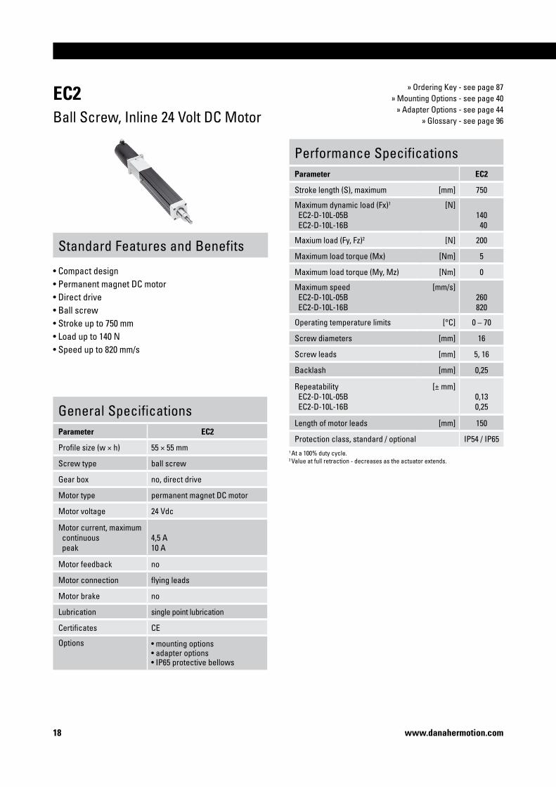
EC�Ball Screw, Inline 24 Volt DC Motor
» Ordering Key - see page 87» Mounting Options - see page 40
» Adapter Options - see page 44» Glossary - see page 96
Standard Features and Benefits
• Compact design • Permanent magnet DC motor• Direct drive• Ball screw• Stroke up to 750 mm• Load up to 140 N• Speed up to 820 mm/s
Performance SpecificationsParameter EC�
Stroke length (S), maximum [mm] 750
Maximum dynamic load (Fx)1
EC2-D-10L-05B EC2-D-10L-16B
[N]140 40
Maxium load (Fy, Fz)2 [N] 200
Maximum load torque (Mx) [Nm] 5
Maximum load torque (My, Mz) [Nm] 0
Maximum speed EC2-D-10L-05B EC2-D-10L-16B
[mm/s]260820
Operating temperature limits [°C] 0 – 70
Screw diameters [mm] 16
Screw leads [mm] 5, 16
Backlash [mm] 0,25
Repeatability EC2-D-10L-05B EC2-D-10L-16B
[± mm]0,130,25
Length of motor leads [mm] 150
Protection class, standard / optional IP54 / IP65
General SpecificationsParameter EC�
Profile size (w × h) 55 × 55 mm
Screw type ball screw
Gear box no, direct drive
Motor type permanent magnet DC motor
Motor voltage 24 Vdc
Motor current, maximum continuous peak
4,5 A10 A
Motor feedback no
Motor connection flying leads
Motor brake no
Lubrication single point lubrication
Certificates CE
Options • mounting options• adapter options• IP65 protective bellows
1 At a 100% duty cycle. 2 Value at full retraction - decreases as the actuator extends.

Precision Linear Actuators
�9www.danahermotion.com
EC�Ball Screw, Inline 24 Volt DC Motor
Retracted length (L tot) [mm] L tot = S max + 255,5
Weight of unit [kg] kg = 4,28 + 0,006 + S max
Performance Diagrams
S max: maximum stroke (ordering stroke in mm) T: top sideL: cover tube length R: right sideL tot: retracted length L: left side
A1: breather tube output cover, 1/8 NPT - 11,1 HEX
Critical Speed vs. Stroke
Column Load Limit vs. Stroke
F: load S: stroke length
1: EC2-D- • • L- • • B
v: speed S: stroke length
1: EC2-D- • • L-05B 2: EC2-D- • • L-16B
V: speed F: load
1: EC2-D-10L-05B2: EC2-D-10L-16B
Speed vs. Load

�0 www.danahermotion.com
EC�Ball Screw, Parallel BK23 AC Servo Motor
» Ordering Key - see page 88» Mounting Options - see page 40
» Adapter Options - see page 44» Glossary - see page 96
Standard Features and Benefits
• Compact design • Brushless AC servo motor• Belt gear or helical gear depending on gear ratio• Ball screw• Stainless steel extension tube• Stroke up to 750 mm• Load up to 3600 N• Speed up to 1280 mm/s
General SpecificationsParameter EC�
Profile size (w × h) 55 × 55 mm
Screw type ball screw
Gear box belt gear (1:1, 1,5:1, 2:1)helical gear (5:1, 10:1)
Motor type brushless AC servo motor
Motor designation AKM23D-EFCNR
Motor feedback resolver
Motor connection connector
Motor brake no, optional
Lubrication single point lubrication
Certificates CE
Options • motor brake (24 Vdc)• mounting options• adapter options• IP65 protective bellows
Performance SpecificationsParameter EC�
Stroke length (S), maximum [mm] 750
Maximum dynamic load (Fx)1
EC2-BK23R-50-05B EC2-BK23R-100-16B EC2-BK23R-20-05B EC2-BK23R-50-16B EC2-BK23R-15-05B EC2-BK23R-10-05B EC2-BK23R-20-16B EC2-BK23R-15-16B EC2-BK23R-10-16B
[N] 3600 2830190014201400 950 590 440 290
Maxium load (Fy, Fz)2 [N] 200
Maximum load torque (Mx) [Nm] 5
Maximum load torque (My, Mz) [Nm] 0
Maximum speed EC2-BK23R-50-05B EC2-BK23R-100-16B EC2-BK23R-20-05B EC2-BK23R-50-16B EC2-BK23R-15-05B EC2-BK23R-10-05B EC2-BK23R-20-16B EC2-BK23R-15-16B EC2-BK23R-10-16B
[mm/s] 60 90 290 180 390 400 920 1250 1280
Operating temperature limits [°C] 0 – 70
Screw diameters [mm] 16
Screw leads [mm] 5, 16
Backlash [mm] 0,25
Repeatability [± mm] 0,013
Protection class, standard / optional IP54 / IP651 At a 100% duty cycle. 2 Value at full retraction - decreases as the actuator extends.

Precision Linear Actuators
��www.danahermotion.com
S max: maximum stroke (ordering stroke in mm) T: top side A1: breather tube output cover, 1/8 NPT - 11,1 HEX A4: with brakeL: cover tube length R: right side A2: connectorL tot: retracted length L: left side A3: without brake
EC�Ball Screw, Parallel BK23 AC Servo Motor
Retracted length (L tot) [mm] L tot = S max + 243,4
Weight of unit [kg] kg = 4,63 + 0,006 + S max
Performance Diagrams
Critical Speed vs. Stroke
Column Load Limit vs. Stroke
F: load S: stroke length
1: EC2-BK23R- • • - • • B
v: speed S: stroke length
1: EC2-BK23R- • • -05B 2: EC2-BK23R- • • -16B
V: speed F: load
1: EC2-BK23R-50-05B2: EC2-BK23R-100-16B3: EC2-BK23R-20-05B4: EC2-BK23R-50-16B5: EC2-BK23R-15-05B
Speed vs. Load
6: EC2-BK23R-10-05B7: EC2-BK23R-20-016B8: EC2-BK23R-15-16B9: EC2-BK23R-10-16B
= Operation in the grey area will reduce life to 25 km of operation!

�� www.danahermotion.com
EC�Ball Screw, Inline BK23 AC Servo Motor
» Ordering Key - see page 88» Mounting Options - see page 40
» Adapter Options - see page 44» Glossary - see page 96
Standard Features and Benefits
• Compact design • Brushless AC servo motor• Direct drive• Ball screw• Stainless steel extension tube• Stroke up to 750 mm• Load up to 950 N• Speed up to 1280 mm/s
Performance SpecificationsParameter EC�
Stroke length (S), maximum [mm] 750
Maximum dynamic load (Fx)1
EC2-BK23R-10L-05B EC2-BK23R-10L-16B
[N]950290
Maxium load (Fy, Fz)2 [N] 200
Maximum load torque (Mx) [Nm] 5
Maximum load torque (My, Mz) [Nm] 0
Maximum speed EC2-BK23R-10L-05B EC2-BK23R-10L-16B
[mm/s] 4001280
Operating temperature limits [°C] 0 – 70
Screw diameters [mm] 16
Screw leads [mm] 5, 16
Backlash [mm] 0,25
Repeatability [± mm] 0,013
Protection class, standard / optional IP54 / IP65General SpecificationsParameter EC�
Profile size (w × h) 55 × 55 mm
Screw type ball screw
Gear box no, direct drive
Motor type brushless AC servo motor
Motor designation AKM23D-EFCNR
Motor feedback resolver
Motor connection connector
Motor brake no, optional
Lubrication single point lubrication
Certificates CE
Options • motor brake (24 Vdc)• mounting options• adapter options• IP65 protective bellows
1 At a 100% duty cycle. 2 Value at full retraction - decreases as the actuator extends.

Precision Linear Actuators
�3www.danahermotion.com
S max: maximum stroke (ordering stroke in mm) T: top side A1: breather tube output cover, 1/8 NPT - 11,1 HEX A4: with brakeL: cover tube length R: right side A2: connectorL tot: retracted length L: left side A3: without brake
EC�Ball Screw, Inline BK23 AC Servo Motor
Retracted length (L tot) [mm] L tot = S max + 220,9
Weight of unit [kg] kg = 4,63 + 0,006 + S max
Performance Diagrams
Critical Speed vs. Stroke
Column Load Limit vs. Stroke
F: load S: stroke length
1: EC2-BK23R- • • L - • • B
v: speed S: stroke length
1: EC2-BK23R- • • L-05B 2: EC2-BK23R- • • L-16B
V: speed F: load
1: EC2-BK23R-10L-05B2: EC2-BK23R-10L-16B
Speed vs. Load

�4 www.danahermotion.com
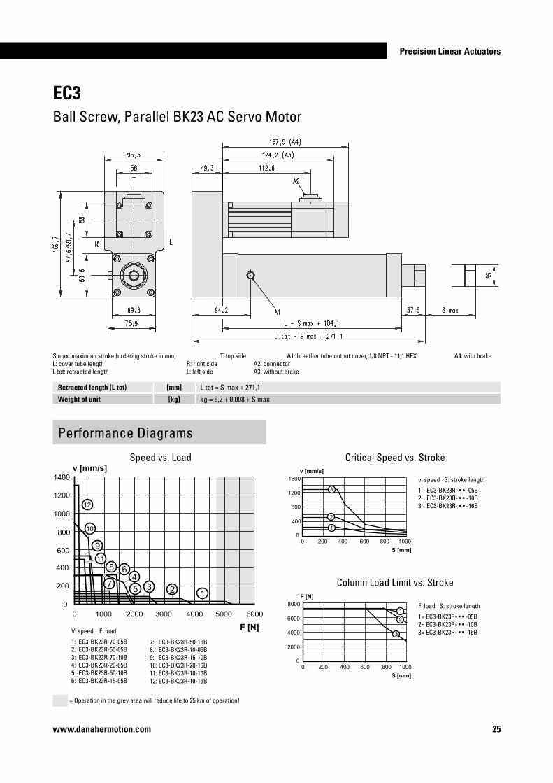
EC3Ball Screw, Parallel BK23 AC Servo Motor
» Ordering Key - see page 89» Mounting Options - see page 40
» Adapter Options - see page 44» Glossary - see page 96
Standard Features and Benefits
• Compact design • Brushless AC servo motor• Belt gear or helical gear depending on gear ratio• Ball screw• Stainless steel extension tube• Stroke up to 1000 mm• Load up to 5390 N• Speed up to 1280 mm/s
General SpecificationsParameter EC3
Profile size (w × h) 68 × 68 mm
Screw type ball screw
Gear box belt gear (1:1, 1,5:1, 2:1)helical gear (5:1, 7:1)
Motor type brushless AC servo motor
Motor designation AKM23D-EFCNR
Motor feedback resolver
Motor connection connector
Motor brake no, optional
Lubrication single point lubrication
Certificates CE
Options • motor brake (24 Vdc)• mounting options• adapter options• IP65 protective bellows
1 At a 100% duty cycle. 2 Value at full retraction - decreases as the actuator extends. 3 16 mm lead = 16 mm diameter. 5 and 10 mm leads = 20 mm diameter.
Performance SpecificationsParameter EC3
Stroke length (S), maximum [mm] 1000
Maximum dynamic load (Fx)1
EC3-BK23R-70-05B EC3-BK23R-50-05B EC3-BK23R-70-10B EC3-BK23R-20-05B EC3-BK23R-50-10B EC3-BK23R-15-05B EC3-BK23R-50-16B EC3-BK23R-10-05B EC3-BK23R-15-10B EC3-BK23R-20-16B EC3-BK23R-10-10B EC3-BK23R-10-16B
[N]5390 388027001950194014201210 950 710 610 480 270
Maxium load (Fy, Fz)2 [N] 200
Maximum load torque (Mx) [Nm] 7,5
Maximum load torque (My, Mz) [Nm] 0
Maximum speed EC3-BK23R-70-05B EC3-BK23R-50-05B EC3-BK23R-70-10B EC3-BK23R-20-05B EC3-BK23R-50-10B EC3-BK23R-15-05B EC3-BK23R-50-16B EC3-BK23R-10-05B EC3-BK23R-15-10B EC3-BK23R-20-16B EC3-BK23R-10-10B EC3-BK23R-10-16B
[mm/s] 35 50 70 260 100 260 160 260 530 890 5301280
Operating temperature limits [°C] 0 – 70
Screw diameters [mm] 16, 20
Screw leads3 [mm] 5, 10, 16
Backlash [mm] 0,25
Repeatability [± mm] 0,013
Protection class, standard / optional IP54 / IP65
Precision Linear Actuators
��www.danahermotion.com
S max: maximum stroke (ordering stroke in mm) T: top side A1: breather tube output cover, 1/8 NPT - 11,1 HEX A4: with brakeL: cover tube length R: right side A2: connectorL tot: retracted length L: left side A3: without brake
EC3Ball Screw, Parallel BK23 AC Servo Motor
Retracted length (L tot) [mm] L tot = S max + 271,1
Weight of unit [kg] kg = 6,2 + 0,008 + S max
Performance Diagrams
Critical Speed vs. Stroke
Column Load Limit vs. Stroke
v: speed S: stroke length
1: EC3-BK23R- • • -05B 2: EC3-BK23R- • • -10B 3: EC3-BK23R- • • -16B
F: load S: stroke length
1= EC3-BK23R- • • -05B2= EC3-BK23R- • • -10B3= EC3-BK23R- • • -16BV: speed F: load
1: EC3-BK23R-70-05B2: EC3-BK23R-50-05B3: EC3-BK23R-70-10B4: EC3-BK23R-20-05B5: EC3-BK23R-50-10B6: EC3-BK23R-15-05B
Speed vs. Load
7: EC3-BK23R-50-16B8: EC3-BK23R-10-05B9: EC3-BK23R-15-10B10: EC3-BK23R-20-16B11: EC3-BK23R-10-10B12: EC3-BK23R-10-16B
= Operation in the grey area will reduce life to 25 km of operation!

�6 www.danahermotion.com
EC3Ball Screw, Parallel BK32 AC Servo Motor
» Ordering Key - see page 89» Mounting Options - see page 40
» Adapter Options - see page 44» Glossary - see page 96
Standard Features and Benefits
• Compact design • Brushless AC servo motor• Belt gear or helical gear depending on gear ratio• Ball screw• Stainless steel extension tube• Stroke up to 1000 mm• Load up to 7200 N• Speed up to 1280 mm/s
General SpecificationsParameter EC3
Profile size (w × h) 68 × 68 mm
Screw type ball screw
Gear box belt gear (1:1, 1,5:1, 2:1)helical gear (5:1, 7:1)
Motor type brushless AC servo motor
Motor designation AKM42G-EKCNR
Motor feedback resolver
Motor connection connector
Motor brake no, optional
Lubrication single point lubrication
Certificates CE
Options • motor brake (24 Vdc)• mounting options• adapter options• IP65 protective bellows
1 At a 100% duty cycle. 2 Value at full retraction - decreases as the actuator extends. 3 16 mm lead = 16 mm diameter. 5 and 10 mm leads = 20 mm diameter.
Performance SpecificationsParameter EC3
Stroke length (S), maximum [mm] 1000
Maximum dynamic load (Fx)1 EC3-BK32R-50-05B EC3-BK32R-70-10B EC3-BK32R-50-10B EC3-BK32R-15-05B EC3-BK32R-50-16B EC3-BK32R-15-10B EC3-BK32R-15-16B EC3-BK32R-10-16B
[N]7200710058804300367021501350 900
Maxium load (Fy, Fz)2 [N] 200
Maximum load torque (Mx) [Nm] 7,5
Maximum load torque (My, Mz) [Nm] 0
Maximum speed EC3-BK32R-50-05B EC3-BK32R-70-10B EC3-BK32R-50-10B EC3-BK32R-15-05B EC3-BK32R-50-16B EC3-BK32R-15-10B EC3-BK32R-15-16B EC3-BK32R-10-16B
[mm/s] 50 70 100 260 160 530 8701280
Operating temperature limits [°C] 0 – 70
Screw diameters [mm] 16, 20
Screw leads3 [mm] 5, 10, 16
Backlash [mm] 0,25
Repeatability [± mm] 0,013
Protection class, standard / optional IP54 / IP65

Precision Linear Actuators
��www.danahermotion.com
S max: maximum stroke (ordering stroke in mm) T: top side A1: breather tube output cover, 1/8 NPT - 11,1 HEX A4: without brakeL: cover tube length R: right side A2: resolver connector A5: with brakeL tot: retracted length L: left side A3: power connector
EC3Ball Screw, Parallel BK32 AC Servo Motor
Performance Diagrams
Retracted length (L tot) [mm] L tot = S max + 271,1
Weight of unit [kg] kg = 8,7 + 0,008 + S max
Critical Speed vs. Stroke
Column Load Limit vs. Stroke
v: speed S: stroke length
1: EC3-BK32R- • • -05B 2: EC3-BK32R- • • -10B 3: EC3-BK32R- • • -16B
F: load S: stroke length
1: EC3-BK32R- • • -05B2: EC3-BK32R- • • -10B3: EC3-BK32R- • • -16BV: speed F: load
1: EC3-BK32R-50-05B2: EC3-BK32R-70-10B3: EC3-BK32R-50-10B4: EC3-BK32R-15-05B
Speed vs. Load
5: EC3-BK32R-50-16B6: EC3-BK32R-15-10B7: EC3-BK32R-15-16B8: EC3-BK32R-10-16B
Operation in the light or dark grey area will reduce life to 25 km of operation= for EC3-BK32R- • • -16B units while operation in the dark grey area will reduce life to 25 km of operation for EC3-BK32R- • • -05B units!
�8 www.danahermotion.com
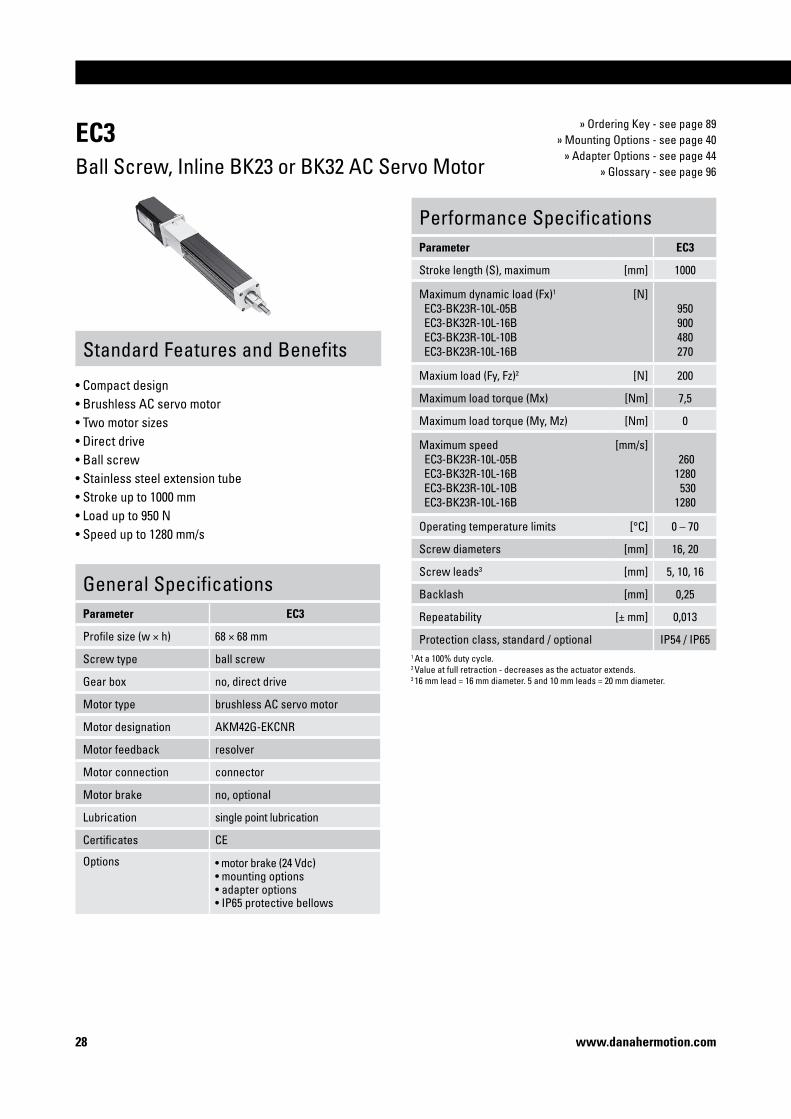
EC3Ball Screw, Inline BK23 or BK32 AC Servo Motor
» Ordering Key - see page 89» Mounting Options - see page 40
» Adapter Options - see page 44» Glossary - see page 96
Standard Features and Benefits
• Compact design • Brushless AC servo motor• Two motor sizes• Direct drive• Ball screw• Stainless steel extension tube• Stroke up to 1000 mm• Load up to 950 N• Speed up to 1280 mm/s
General SpecificationsParameter EC3
Profile size (w × h) 68 × 68 mm
Screw type ball screw
Gear box no, direct drive
Motor type brushless AC servo motor
Motor designation AKM42G-EKCNR
Motor feedback resolver
Motor connection connector
Motor brake no, optional
Lubrication single point lubrication
Certificates CE
Options • motor brake (24 Vdc)• mounting options• adapter options• IP65 protective bellows
Performance SpecificationsParameter EC3
Stroke length (S), maximum [mm] 1000
Maximum dynamic load (Fx)1
EC3-BK23R-10L-05B EC3-BK32R-10L-16B EC3-BK23R-10L-10B EC3-BK23R-10L-16B
[N]950900480270
Maxium load (Fy, Fz)2 [N] 200
Maximum load torque (Mx) [Nm] 7,5
Maximum load torque (My, Mz) [Nm] 0
Maximum speed EC3-BK23R-10L-05B EC3-BK32R-10L-16B EC3-BK23R-10L-10B EC3-BK23R-10L-16B
[mm/s] 2601280 5301280
Operating temperature limits [°C] 0 – 70
Screw diameters [mm] 16, 20
Screw leads3 [mm] 5, 10, 16
Backlash [mm] 0,25
Repeatability [± mm] 0,013
Protection class, standard / optional IP54 / IP651 At a 100% duty cycle. 2 Value at full retraction - decreases as the actuator extends. 3 16 mm lead = 16 mm diameter. 5 and 10 mm leads = 20 mm diameter.

Precision Linear Actuators
�9www.danahermotion.com
EC3Ball Screw, Inline BK23 or BK32 AC Servo Motor
Retracted length (L tot) [mm] L tot = S max + 298,1
Weight of unit [kg] EC3-BK23R-10L: kg = 6,2 + 0,008 + S maxEC3-BK32R-10L: kg = 8,7 + 0,008 + S max
Performance Diagrams
EC3-BK23R-10L
EC3-BK32R-10L
S max: maximum stroke (ordering stroke in mm) T: top side A1: breather tube output cover, 1/8 NPT - 11,1 HEX A4: without brakeL: cover tube length R: right side A2: resolver connector A5: with brakeL tot: retracted length L: left side A3: power connector
S max: maximum stroke (ordering stroke in mm) T: top side A1: breather tube output cover, 1/8 NPT - 11,1 HEX A4: with brakeL: cover tube length R: right side A2: connectorL tot: retracted length L: left side A3: without brake
Critical Speed vs. Stroke
Column Load Limit vs. Stroke
v: speed S: stroke length
1: EC3-BK23R- • • L-05B 2: EC3-BK23R- • • L-10B 3: EC3-BK23(32)R- • • L-16B
F: load S: stroke length
1: EC3-BK23R- • •L-05B2: EC3-BK23R- • • L-10B3: EC3-BK23(32)R- • • L-16B
V: speed F: load
1: EC3-BK23R-10L-05B2: EC3-BK32R-10L-16B3: EC3-BK23R-10L-10B4: EC3-BK23R-10L-16B
Speed vs. Load

30 www.danahermotion.com
EC4Ball Screw, Parallel BK32 AC Servo Motor
» Ordering Key - see page 90» Mounting Options - see page 40
» Adapter Options - see page 44» Glossary - see page 96
Standard Features and Benefits
• Compact design • Brushless AC servo motor• Belt gear or helical gear depending on gear ratio• Ball screw• Stainless steel extension tube• Stroke up to 1500 mm• Load up to 12000 N• Speed up to 1330 mm/s
General SpecificationsParameter EC4
Profile size (w × h) 94 × 94 mm
Screw type ball screw
Gear box belt gear (1:1, 1,5:1, 2:1)helical gear (5:1, 10:1)
Motor type brushless AC servo motor
Motor designation AKM42G-EKCNR
Motor feedback resolver
Motor connection connector
Motor brake no, optional
Lubrication single point lubrication
Certificates CE
Options • motor brake (24 Vdc)• mounting options• adapter options• IP65 protective bellows
Performance SpecificationsParameter EC4
Stroke length (S), maximum [mm] 1500
Maximum dynamic load (Fx)1
EC4-BK32R-100-05B EC4-BK32R-50-10B EC4-BK32R-100-25B EC4-BK32R-20-10B EC4-BK32R-50-25B EC4-BK32R-15-10B EC4-BK32R-20-25B EC4-BK32R-15-25B EC4-BK32R-10-25B
[N] 12000 7020 5500 2870 2800 2160 1150 860 570
Maxium load (Fy, Fz)2 [N] 200
Maximum load torque (Mx) [Nm] 10
Maximum load torque (My, Mz) [Nm] 0
Maximum speed EC4-BK32R-100-05B EC4-BK32R-50-10B EC4-BK32R-100-25B EC4-BK32R-20-10B EC4-BK32R-50-25B EC4-BK32R-15-10B EC4-BK32R-20-25B EC4-BK32R-15-25B EC4-BK32R-10-25B
[mm/s] 27 50 65 410 130 530 1020 1330 1330
Operating temperature limits [°C] 0 – 70
Screw diameters [mm] 25
Screw leads [mm] 10, 25
Backlash [mm] 0,30
Repeatability [± mm] 0,013
Protection class, standard / optional IP54 / IP651 At a 100% duty cycle. 2 Value at full retraction - decreases as the actuator extends.

Precision Linear Actuators
3�www.danahermotion.com
S max: maximum stroke (ordering stroke in mm) T: top side A1: breather tube output cover, 1/4 NPT - 14,0 HEX A4: without brakeL: cover tube length R: right side A2: resolver connector A5: with brakeL tot: retracted length L: left side A3: power connector
EC4Ball Screw, Parallel BK32 AC Servo Motor
Retracted length (L tot) [mm] L tot = S max + 406,9
Weight of unit [kg] kg = 16,7 + 0,0188 + S max
Performance Diagrams
Critical Speed vs. Stroke
Column Load Limit vs. Stroke
v: speed S: stroke length
1: EC4-BK32R- • • -10B 2: EC4-BK32R- • • -25B
F: load S: stroke length
1: EC4-BK32R- • • -10B 2: EC4-BK32R- • • -25B
V: speed F: load
1: EC4-BK32R-100-05B2: EC4-BK32R-50-10B 3: EC4-BK32R-100-25B4: EC4-BK32R-20-10B5: EC4-BK32R-50-25B
Speed vs. Load
6: EC4-BK32R-10-15B7: EC4-BK32R-20-25B8: EC4-BK32R-15-25B9: EC4-BK32R-10-25B

3� www.danahermotion.com
EC4Ball Screw, Inline BK32 AC Servo Motor
» Ordering Key - see page 90» Mounting Options - see page 40
» Adapter Options - see page 44» Glossary - see page 96
Standard Features and Benefits
• Compact design • Brushless AC servo motor• Direct drive• Ball screw• Stainless steel extension tube• Stroke up to 1500 mm• Load up to 570 N• Speed up to 1330 mm/s
General SpecificationsParameter EC4
Profile size (w × h) 94 × 94 mm
Screw type ball screw
Gear box no, direct drive
Motor type brushless AC servo motor
Motor designation AKM42G-EKCNR
Motor feedback resolver
Motor connection connector
Motor brake no, optional
Lubrication single point lubrication
Certificates CE
Options • motor brake (24 Vdc)• mounting options• adapter options• IP65 protective bellows
Performance SpecificationsParameter EC4
Stroke length (S), maximum [mm] 1500
Maximum dynamic load (Fx)1
EC4-BK32R-10L-25B [N]
570
Maxium load (Fy, Fz)2 [N] 200
Maximum load torque (Mx) [Nm] 10
Maximum load torque (My, Mz) [Nm] 0
Maximum speed EC4-BK32R-10L-25B
[mm/s]1330
Operating temperature limits [°C] 0 – 70
Screw diameters [mm] 25
Screw leads [mm] 10, 25
Backlash [mm] 0,30
Repeatability [± mm] 0,013
Protection class, standard / optional IP54 / IP651 At a 100% duty cycle. 2 Value at full retraction - decreases as the actuator extends.

Precision Linear Actuators
33www.danahermotion.com
S max: maximum stroke (ordering stroke in mm) T: top side A1: breather tube output cover, 1/4 NPT - 14,0 HEX A4: without brakeL: cover tube length R: right side A2: resolver connector A5: with brakeL tot: retracted length L: left side A3: power connector
EC4Ball Screw, Inline BK32 AC Servo Motor
Retracted length (L tot) [mm] L tot = S max + 425,3
Weight of unit [kg] kg = 16,7 + 0,0188 + S max
Performance Diagrams
Critical Speed vs. Stroke
Column Load Limit vs. Stroke
v: speed S: stroke length
1: EC4-BK32R- • • -10B 2: EC4-BK32R- • • -25B
F: load S: stroke length
1: EC4-BK32R- • • -10B 2: EC4-BK32R- • • -25B
V: speed F: load
1: EC4-BK32R-10L-25B
Speed vs. Load

34 www.danahermotion.com
EC�Ball Screw, Parallel BK32 AC Servo Motor
» Ordering Key - see page 91» Mounting Options - see page 40
» Adapter Options - see page 44» Glossary - see page 96
Standard Features and Benefits
• Compact design • Brushless AC servo motor• Belt gear or helical gear depending on gear ratio• Ball screw• Stainless steel extension tube• Stroke up to 1500 mm• Load up to 13750 N• Speed up to 1330 mm/s
General SpecificationsParameter EC�
Profile size (w × h) 94 × 94 mm
Screw type ball screw
Gear box belt gear (1:1, 1,5:1, 2:1)helical gear (5:1, 10:1)
Motor type brushless AC servo motor
Motor designation AKM42G-EKCNR
Motor feedback resolver
Motor connection connector
Motor brake no, optional
Lubrication single point lubrication
Certificates CE
Options • motor brake (24 Vdc)• mounting options• adapter options• IP65 protective bellows
Performance SpecificationsParameter EC�
Stroke length (S), maximum [mm] 1500
Maximum dynamic load (Fx)1
EC5-BK32R-100-10B EC5-BK32R-50-10B EC5-BK32R-100-32B EC5-BK32R-20-10B EC5-BK32R-50-32B EC5-BK32R-15-10B EC5-BK32R-20-32B EC5-BK32R-15-32B EC5-BK32R-10-32B
[N]13750 7020 4290 2870 2190 2160 900 670 450
Maxium load (Fy, Fz)2 [N] 200
Maximum load torque (Mx) [Nm] 10
Maximum load torque (My, Mz) [Nm] 0
Maximum speed EC5-BK32R-100-10B EC5-BK32R-50-10B EC5-BK32R-100-32B EC5-BK32R-20-10B EC5-BK32R-50-32B EC5-BK32R-15-10B EC5-BK32R-20-32B EC5-BK32R-15-32B EC5-BK32R-10-32B
[mm/s] 26 52 85 390 170 390131013301330
Operating temperature limits [°C] 0 – 70
Screw diameters [mm] 32
Screw leads [mm] 10, 32
Backlash [mm] 0,30
Repeatability [± mm] 0,013
Protection class, standard / optional IP54 / IP651 At a 100% duty cycle. 2 Value at full retraction - decreases as the actuator extends.
Precision Linear Actuators
3�www.danahermotion.com
S max: maximum stroke (ordering stroke in mm) T: top side A1: breather tube output cover, 1/4 NPT - 14,0 HEX A4: without brakeL: cover tube length R: right side A2: resolver connector A5: with brakeL tot: retracted length L: left side A3: power connector
EC�Ball Screw, Parallel BK32 AC Servo Motor
Retracted length (L tot) [mm] L tot = S max + 406,9
Weight of unit [kg] kg =16,7 + 0,0188 + S max
Performance Diagrams
Critical Speed vs. Stroke
Column Load Limit vs. Stroke
v: speed S: stroke length
1: EC5-BK32R- • • -10B 2: EC5-BK32R- • • -32B
F: load S: stroke length
1: EC5-BK32R- • • - • • B
V: speed F: load
1: EC5-BK32R-100-10B2: EC5-BK32R-50-10B3: EC5-BK32R-100-32B4: EC5-BK32R-20-10B5: EC5-BK32R-50-32B
Speed vs. Load
6: EC5-BK32R-15-10B7: EC5-BK32R-20-32B8: EC5-BK32R-15-32B9: EC5-BK32R-10-32B

36 www.danahermotion.com
EC�Ball Screw, Parallel BK42 AC Servo Motor
» Ordering Key - see page 91» Mounting Options - see page 40
» Adapter Options - see page 44» Glossary - see page 96
Standard Features and Benefits
• Compact design • Brushless AC servo motor• Belt gear or helical gear depending on gear ratio• Ball screw• Stainless steel extension tube• Stroke up to 1500 mm• Load up to 25000 N• Speed up to 1090 mm/s
General SpecificationsParameter EC�
Profile size (w × h) 94 × 94 mm
Screw type ball screw
Gear box belt gear (1:1, 1,5:1, 2:1)helical gear (5:1, 10:1)
Motor type brushless AC servo motor
Motor designation AKM52G-BSCNR-02
Motor feedback resolver
Motor connection connector
Motor brake no, optional
Lubrication single point lubrication
Certificates CE
Options • motor brake (24 Vdc)• mounting options• adapter options• IP65 protective bellows
Performance SpecificationsParameter EC�
Stroke length (S), maximum [mm] 1500
Maximum dynamic load (Fx)1
EC5-BK42R-100-10B EC5-BK42R-50-10B EC5-BK42R-100-32B EC5-BK42R-20-10B EC5-BK42R-15-10B EC5-BK42R-20-32B EC5-BK42R-15-32B EC5-BK42R-10-32B
[N]250001675010250 6860 5140 2140 1600 1070
Maxium load (Fy, Fz)2 [N] 200
Maximum load torque (Mx) [Nm] 10
Maximum load torque (My, Mz) [Nm] 0
Maximum speed EC5-BK42R-100-10B EC5-BK42R-50-10B EC5-BK42R-100-32B EC5-BK42R-20-10B EC5-BK42R-15-10B EC5-BK42R-20-32B EC5-BK42R-15-32B EC5-BK42R-10-32B
[mm/s] 26 52 85 170 220 545 725 1090
Operating temperature limits [°C] 0 – 70
Screw diameters [mm] 32
Screw leads [mm] 10, 32
Backlash [mm] 0,30
Repeatability [± mm] 0,013
Protection class, standard / optional IP54 / IP651 At a 100% duty cycle. 2 Value at full retraction - decreases as the actuator extends.

Precision Linear Actuators
3�www.danahermotion.com
EC�Ball Screw, Parallel BK42 AC Servo Motor
Retracted length (L tot) [mm] L tot = S max + 406,9
Weight of unit [kg] kg = 20,4 + 0,0188 + S max
S max: maximum stroke (ordering stroke in mm) T: top side A1: breather tube output cover, 1/4 NPT - 14,0 HEX A4: without brakeL: cover tube length R: right side A2: resolver connector A5: with brakeL tot: retracted length L: left side A3: power connector
Performance Diagrams
Critical Speed vs. Stroke
Column Load Limit vs. Stroke
v: speed S: stroke length
1: EC5-BK42R- • • -10B 2: EC5-BK42R- • • -32B
F: load S: stroke length
1: EC5-BK42R- • • - • • B
V: speed F: load
1: EC5-BK42R-100-10B2: EC5-BK42R-50-10B3: EC5-BK42R-100-32B4: EC5-BK42R-20-10B
Speed vs. Load
5: EC5-BK42R-15-10B6: EC5-BK42R-20-32B7: EC5-BK42R-15-32B8: EC5-BK42R-10-32B
= Operation in the grey area will reduce life to 25 km of operation!

38 www.danahermotion.com
EC�Ball Screw, Inline BK32 or BK42 AC Servo Motor
» Ordering Key - see page 91» Mounting Options - see page 40
» Adapter Options - see page 44» Glossary - see page 96
Standard Features and Benefits
• Compact design • Brushless AC servo motor• Two motor sizes• Direct drive• Ball screw• Stainless steel extension tube• Stroke up to 1500 mm• Load up to 1070 N• Speed up to 1330 mm/s
General SpecificationsParameter EC�
Profile size (w × h) 94 × 94 mm
Screw type ball screw
Gear box no, direct drive
Motor type brushless AC servo motor
Motor designation EC5-BK32R EC5-BK42R
AKM42G-EKCNRAKM52G-BSCNR-02
Motor feedback resolver
Motor connection connector
Motor brake no, optional
Lubrication single point lubrication
Certificates CE
Options • motor brake (24 Vdc)• mounting options• adapter options• IP65 protective bellows
Performance SpecificationsParameter EC�
Stroke length (S), maximum [mm] 1500
Maximum dynamic load (Fx)1
EC5-BK42R-10L-32B EC5-BK32R-10L-32B
[N]1070 450
Maxium load (Fy, Fz)2 [N] 200
Maximum load torque (Mx) [Nm] 10
Maximum load torque (My, Mz) [Nm] 0
Maximum speed EC5-BK42R-10L-32B EC5-BK32R-10L-32B
[mm/s]1090 1330
Operating temperature limits [°C] 0 – 70
Screw diameters [mm] 32
Screw leads [mm] 10, 32
Backlash [mm] 0,30
Repeatability [± mm] 0,013
Protection class, standard / optional IP54 / IP65
1 At a 100% duty cycle. 2 Value at full retraction - decreases as the actuator extends.

Precision Linear Actuators
39www.danahermotion.com
EC�Ball Screw, Inline BK32 or BK42 AC Servo Motor
Retracted length (L tot) [mm] L tot = S max + 425,3
Weight of unit [kg] EC5-BK32R-10L: kg =16,7 + 0,0188 + S maxEC5-BK42R-10L: kg = 20,4 + 0,0188 + S max
S max: maximum stroke (ordering stroke in mm) T: top side A1: breather tube output cover, 1/4 NPT - 14,0 HEX A4: without brakeL: cover tube length R: right side A2: resolver connector A5: with brakeL tot: retracted length L: left side A3: power connector
EC5-BK32R-10L
EC5-BK42R-10L
Performance Diagrams
Critical Speed vs. Stroke
Column Load Limit vs. Stroke
v: speed S: stroke length
1: EC5-BK32(42)R- • • L-32B
F: load S: stroke length
1: EC5-BK32(42)R- • • L- • • B
V: speed F: load
1: EC5-BK42R-10L-32B2: EC5-BK32R-10L-32B
Speed vs. Load

40 www.danahermotion.com
EC SeriesMounting Options
Front Flange type MF1M
The flange comes mounted from factory. Flange dimensions in accordance with ISO6431 for 50 mm (EC2), 63 mm (EC3) or 80 mm (EC4 and EC5) bore size.
Rear Flange type MF2M
The flange comes mounted from factory. Flange dimensions in accordance with ISO6431 for 50 mm (EC2), 63 mm (EC3) or 100 mm (EC4 and EC5) bore size.
Front and Rear Flanges type MF3M
The flanges comes mounted from factory. Flange dimensions in accordance with ISO6431 for 50 mm (EC2 and (EC3) or 100 mm (EC4 and EC5) bore size.
A B C D E F
EC2 90,0 114,3 45 63,5 9,5 9,0
EC3 100,0 127,0 50 69,1 12,7 9,0
EC4 126,0 152,4 63 96,3 12,7 12,0
EC5 150,0 186,9 75 114,3 19,1 14,0 / 14,4
A B C D E F
EC2 90,0 114,3 45,0 63,5 9,5 9,0
EC3 100,0 127,0 50,0 69,1 12,7 9,0
EC4 126,0 152,4 63,0 96,3 12,7 12,0
EC5 150,0 186,9 75,0 114,3 19,1 14,0 / 14,4
A B C D E F
EC2 90,0 114,3 45,0 63,5 9,5 9,0
EC3 100,0 127,0 50,0 69,1 12,7 9,0
EC4 126,0 152,4 63,0 96,3 12,7 12,0
EC5 150,0 186,9 75,0 114,3 19,1 14,0 / 14,4

Precision Linear Actuators
4�www.danahermotion.com
EC SeriesMounting Options
Side End Angel Brackets type MS1
The feets comes mounted from factory.
Mounting Feet type MS2
The brackets comes mounted from factory.
A B C D E F G H
EC2 38,0 57,2 9,5 153,7 288,8 + S max 12,0 9,0 7,3
EC3 45,0 69,6 9,7 182,4 325,4 + S max 14,0 11,0 9,1
EC4 31,8 50,8 3,2 225,7 403,9 + S max 9,5 11,1 7,7
EC5 not available
A B C D E F G
EC2 85,0 114,3 9,5 22,1 11,0 144,8 + S max 9,0
EC3 100,0 127,0 12,7 25,0 12,5 158,8 + S max 11,0
EC4 140,0 181,1 19,1 38,1 19,1 242,6 + S max 18,0
EC5 140,0 181,1 19,1 38,1 19,1 242,6 + S max 18,0

4� www.danahermotion.com
EC SeriesMounting Options
Rear Clevis without Pivot Base type MP2
The MP3 rear clevis kit consists of a MP2 kit plus a pivot base. Clevis dimensions in accordance with ISO6431 for 50 mm (EC2), 63 mm (EC3) or 100 mm (EC4 and EC5) bore size.
Rear Clevis with Pivot Base type MP3
The clevis comes mounted from factory. Clevis dimensions in accordance with ISO6431 for 50 mm (EC2), 63 mm (EC3) or 100 mm (EC4 and EC5) bore size.
A B C D E F
EC2 32,0 / 32,6 57,0 15,7 12,7 11,95 / 12,00 98,3
EC3 40,0 / 40,6 69,3 21,8 15,2 15,95 / 16,00 103,9
EC4 60,0 / 60,5 91,4 28,7 19,6 19,95 / 20,00 166,6
EC5 60,0 / 60,5 91,4 28,7 19,6 19,95 / 20,00 166,6
A B C D E F
EC2 56,9 70,0° 9,5 25,4 5,4 61,7
EC3 69,3 80,0° 9,5 31,5 6,5 76,0
EC4 91,4 80,0° 15,7 44,4 11,1 98,8
EC5 91,4 80,0° 15,7 44,4 11,1 98,8* B = maximum pivot angle

Precision Linear Actuators
43www.danahermotion.com
EC SeriesMounting Options
Side Tapped Holes type MS6M
The trunnion comes mounted from factory. Trunnion dimensions in accordance with ISO6431 for 50 mm (EC2), 63 mm (EC3) or 100 mm (EC4 and EC5) bore size.
Trunninon type MT4
The holes comes drilled and tapped from factory.
A B C D E F
EC2 22,1 22,1 25,0 144,8 + S max 11,0 M8 × 8,4
EC3 25,1 25,0 30,0 158,8 + S max 12,5 M10 × 10,2
EC4 40,0 40,0 40,6 242,6 + S max 19,1 M16 × 14,0
EC5 40,0 40,0 40,6 242,6 + S max 19,1 M16 × 14,0
A B C D E F G
EC2 75,0 106,9 28,5 74,7 19,1 155,8 + S max ø 15,92 / 15,97
EC3 90,0 129,6 38,6 87,6 / 89,7 25,0 171,2 + S max ø 19,91 / 19,96
EC4 131,8 181,8 48,0 111,1 31,8 261,6 + S max ø 24,91 / 24,96
EC5 131,8 181,8 48,0 111,1 31,8 261,6 + S max ø 24,91 / 24,96
Parallel versions
A B C D E
EC2 75,0 106,9 19,1 155,8 + S max ø 15,92 / 15,97
EC3 90,0 129,6 25,0 171,2 + S max ø 19,91 / 19,96
EC4 131,8 181,6 31,8 261,6 + S max ø 24,91 / 24,96
EC5 131,8 181,6 31,8 261,6 + S max ø 24,91 / 24,96
Inline versions

44 www.danahermotion.com
EC SeriesAdapter Options
Inside Threads type FT1M
Outside Threads type MT1M
Inside thread means that the cover tube adapter consist of a threaded hole.
A B C D E
EC2 28,0 12,0 25,4 M16 × 2 19,0
EC3 35,0 17,2 31,75 M16 × 2 25,0
EC4 50,0 20,0 47,6 M20 × 1,5 31,0
EC5 50,0 20,0 47,6 M24 × 2 31,0
Inside thread means that the cover tube adapter consist of a threaded pin.
A B C D E
EC2 35,0 17,2 32,0 31,8 M16 × 2
EC3 35,0 17,2 32,0 31,8 M16 × 2
EC4 50,0 20,0 40,0 47,6 M20 × 1,5
EC5 50,0 20,0 40,0 47,6 M24 × 2

Precision Linear Actuators
4�www.danahermotion.com
EC SeriesAdapter Options
Spherical Joint type FS2
Clevis with Pin type FC2
The spherical joint comes mounted from factory. It includes a jam nut to lock the joint in position.
A B C D E F
EC2 21,0 38,0 92,2 73,2 16,1 / 16,0 25,4
EC3 21,0 38,0 92,2 73,2 16,1 / 16,0 31,8
EC4 25,0 46,0 111,0 88,0 20,1 / 20,0 47,6
EC5 31,0 60,0 138,5 108,5 25,0 / 24,9 47,6
The clevis comes mounted from factory. Included is a pin, a pin lock and a jam nut to lock the clevis in position.
A B C D E F G H
EC2 32,0 16,0 92,2 73,2 32,0 32,0 16,0 / 15,9 25,4
EC3 32,0 16,0 92,2 73,2 32,0 32,0 16,0 / 15,9 31,8
EC4 40,0 20,0 116,0 91,0 40,0 40,0 20,0 / 19,9 47,6
EC5 50,0 25,0 145,5 113,5 50,0 50,0 25,0 / 24,9 47,6

46 www.danahermotion.com
EC SeriesOther Options
Protective Bellows type PB
The protective bellows option is a durable bellows made of polyurethane which protects the unit from dust, dirt, and liquids. A unit equipped with protective bellows is protected to IP65. The bellows will reduce the available stroke of the unit, as extra space is needed when retracting. They will also increase the diameter of the extension tube. The amount of stroke reduction and bellows diameter are indicated in the table.
Stroke Reducement TableModel Stroke
[mm]Reduced stroke [mm]
Bellows diameter [mm]
EC2 0 - 149 30 64
150 - 299 47
300 - 449 65
450 - 600 82
601 - 750 95
EC3 0 - 199 37 76
200 - 399 54
400 - 599 72
600 - 800 90
801 - 1000 103
EC4, EC5 0 - 249 41 95
250 - 499 63
500 - 749 85
750 - 999 106
1000 - 1249 128
1250 - 1500 151
Thrust Tube Protective BootEC ActuatorActuator Extension tube Protective bellows

Precision Linear Actuators
4�www.danahermotion.com
EC SeriesAccessories
Magnetic Sensors
The magnetic sensors are mounted directly in the sensor slots on both sides of the profile of the units. They require no additional mounting bracket. The sensor is fixed in position by a single locking screw. The cable is molded into the sensor. Sensors are ordered by using the part numbers.
Technical SpecificationParameter
Max. power [W] 6
Max. voltage [V] 120
Max. current [A] 0,05
LED indicator for switch yes
Protection class IP67
Cable length [m] 3
Operating temperature limits [°C] -20 – 70
Part NumbersSensor type suitable units p/n
Normally closed EC2, EC3, EC4, EC5 PSR-2
Normally open EC2, EC3, EC4, EC5 PSR-1
brown
blue
brown
blue
A B
EC2 37,3 28,5
EC3 43,7 34,8
EC4 54,5 46,1
EC5 54,5 46,1

48 www.danahermotion.com
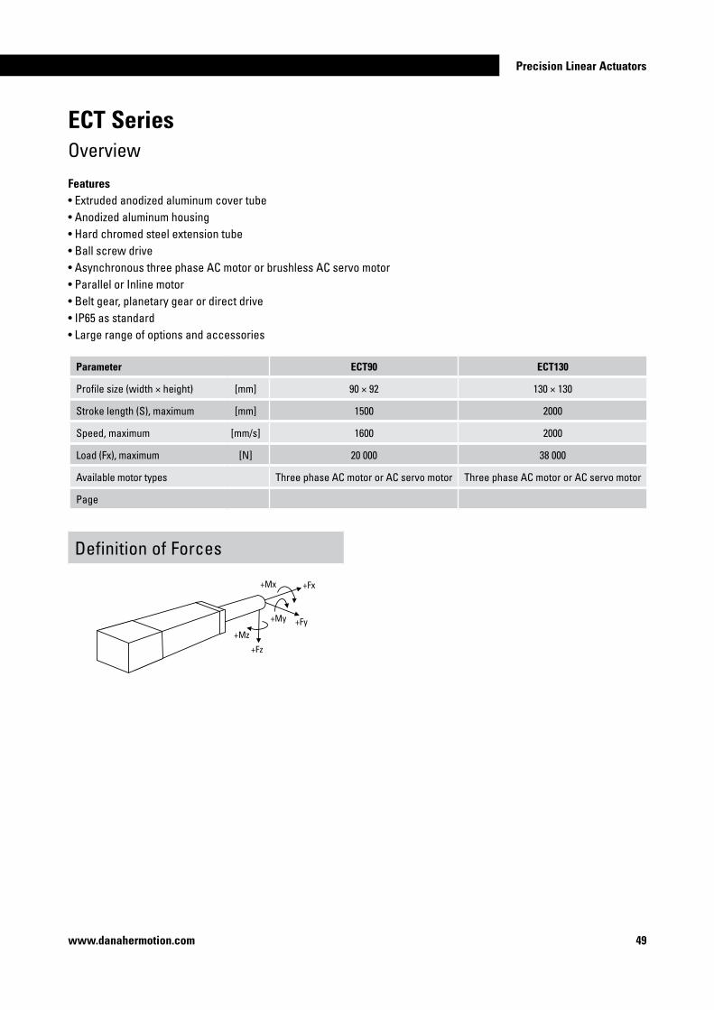
ECT SeriesIntroduction
The ECT series is our highest performing line of precision linear actuators. Designed for the most demanding applications, the ECT series is ideal when the maximum available performance and longest life cycle are required. Precision-rolled ball screws provide smooth motion, accurate positioning, and quiet operation. The ECT series guarantees trouble-free operation even in the toughest applications.
Precision Linear Actuators
49www.danahermotion.com
Parameter ECT90 ECT�30
Profile size (width × height) [mm] 90 × 92 130 × 130
Stroke length (S), maximum [mm] 1500 2000
Speed, maximum [mm/s] 1600 2000
Load (Fx), maximum [N] 20 000 38 000
Available motor types Three phase AC motor or AC servo motor Three phase AC motor or AC servo motor
Page
ECT SeriesOverview
Features• Extruded anodized aluminum cover tube• Anodized aluminum housing• Hard chromed steel extension tube• Ball screw drive• Asynchronous three phase AC motor or brushless AC servo motor• Parallel or Inline motor• Belt gear, planetary gear or direct drive• IP65 as standard• Large range of options and accessories
Definition of Forces
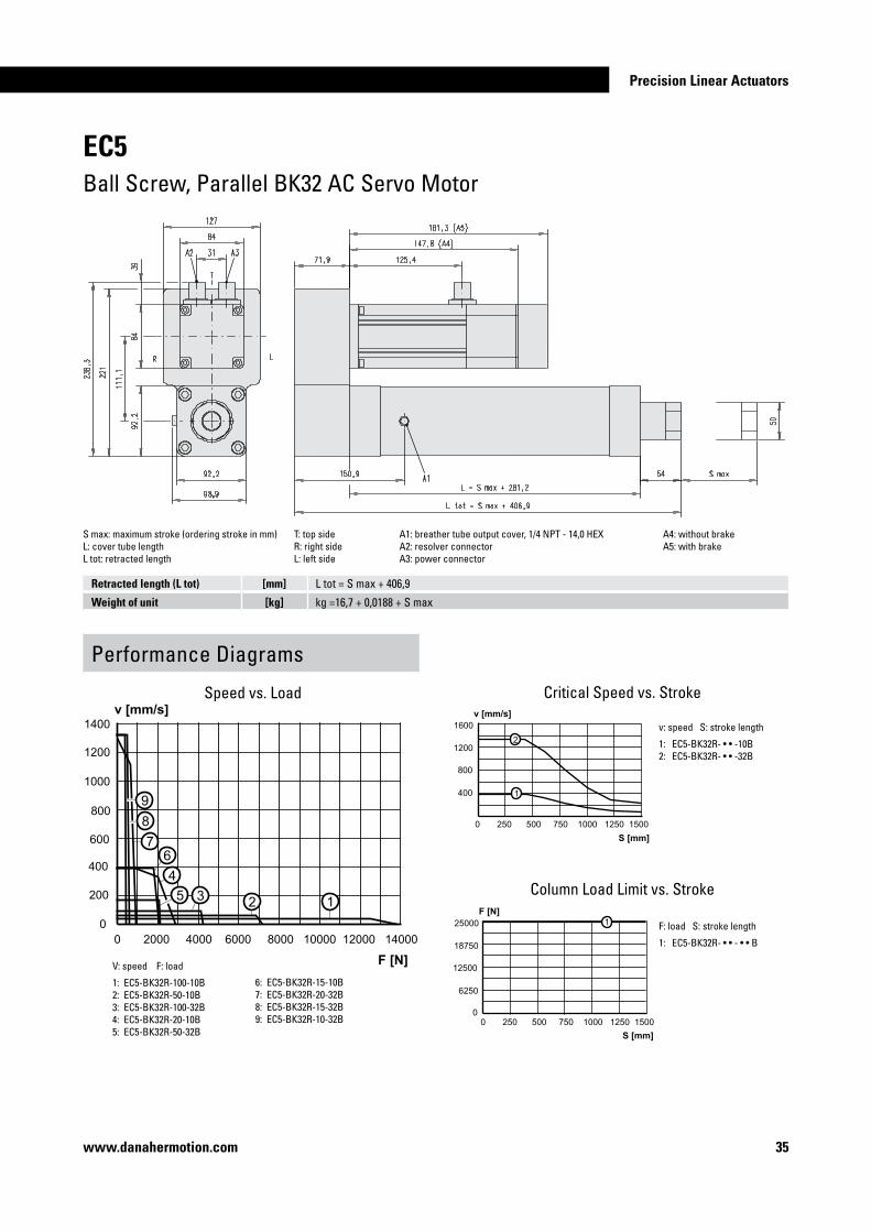
�0 www.danahermotion.com
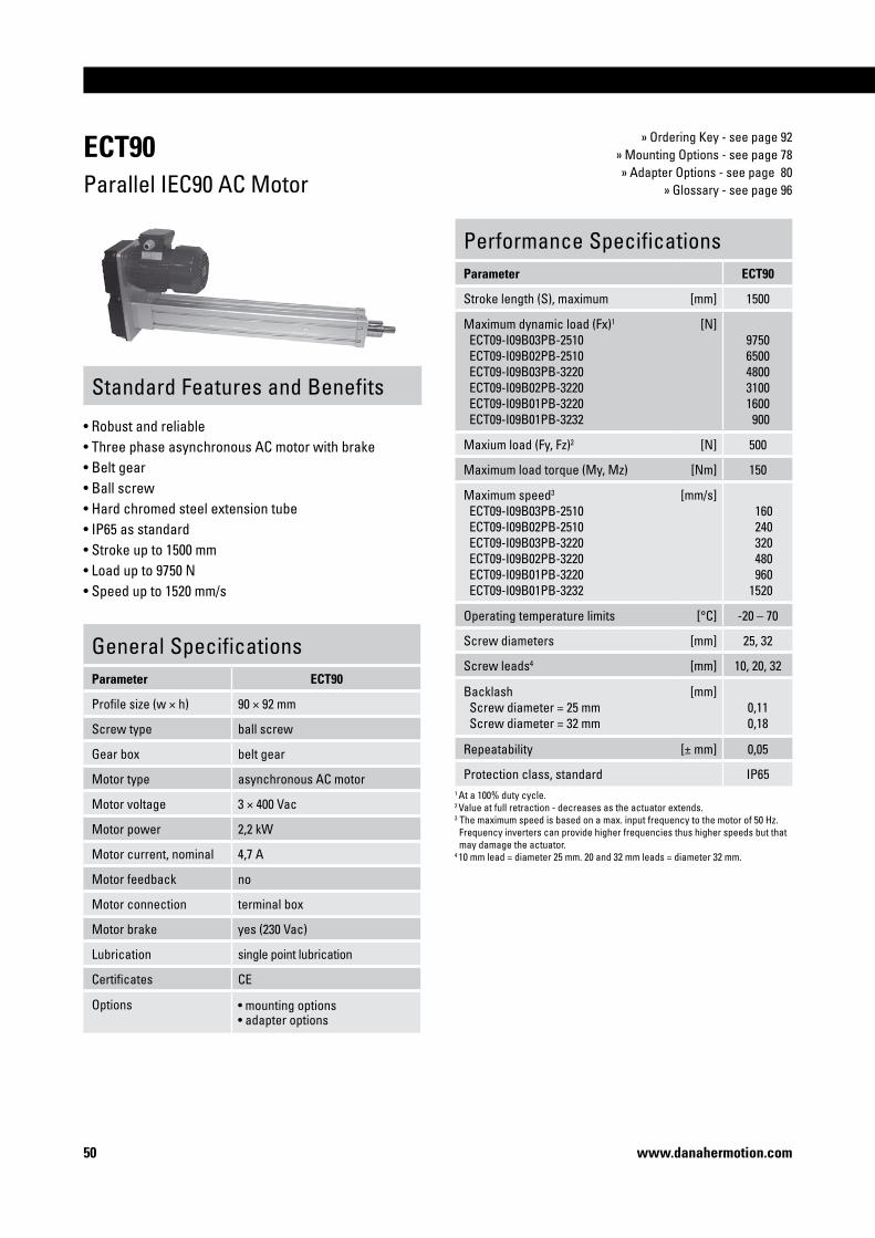
ECT90Parallel IEC90 AC Motor
» Ordering Key - see page 92» Mounting Options - see page 78» Adapter Options - see page 80
» Glossary - see page 96
Standard Features and Benefits
• Robust and reliable • Three phase asynchronous AC motor with brake• Belt gear• Ball screw• Hard chromed steel extension tube• IP65 as standard• Stroke up to 1500 mm• Load up to 9750 N• Speed up to 1520 mm/s
General SpecificationsParameter ECT90
Profile size (w × h) 90 × 92 mm
Screw type ball screw
Gear box belt gear
Motor type asynchronous AC motor
Motor voltage 3 × 400 Vac
Motor power 2,2 kW
Motor current, nominal 4,7 A
Motor feedback no
Motor connection terminal box
Motor brake yes (230 Vac)
Lubrication single point lubrication
Certificates CE
Options • mounting options• adapter options
Performance SpecificationsParameter ECT90
Stroke length (S), maximum [mm] 1500
Maximum dynamic load (Fx)1
ECT09-I09B03PB-2510 ECT09-I09B02PB-2510 ECT09-I09B03PB-3220 ECT09-I09B02PB-3220 ECT09-I09B01PB-3220 ECT09-I09B01PB-3232
[N]97506500480031001600 900
Maxium load (Fy, Fz)2 [N] 500
Maximum load torque (My, Mz) [Nm] 150
Maximum speed3
ECT09-I09B03PB-2510 ECT09-I09B02PB-2510 ECT09-I09B03PB-3220 ECT09-I09B02PB-3220 ECT09-I09B01PB-3220 ECT09-I09B01PB-3232
[mm/s] 160 240 320 480 960 1520
Operating temperature limits [°C] -20 – 70
Screw diameters [mm] 25, 32
Screw leads4 [mm] 10, 20, 32
Backlash Screw diameter = 25 mm Screw diameter = 32 mm
[mm]0,110,18
Repeatability [± mm] 0,05
Protection class, standard IP651 At a 100% duty cycle. 2 Value at full retraction - decreases as the actuator extends. 3 The maximum speed is based on a max. input frequency to the motor of 50 Hz. Frequency inverters can provide higher frequencies thus higher speeds but that may damage the actuator.4 10 mm lead = diameter 25 mm. 20 and 32 mm leads = diameter 32 mm.

Precision Linear Actuators
��www.danahermotion.com
ECT90Parallel IEC90 AC Motor
S max: maximum stroke (ordering stroke in mm) L tot: retracted lengthL: cover tube length A1: ECT09-I09B • • PB-25 = 15 mm, ECT09-I09B • • PB-32 = 12 mm
Cover tube length (L) [mm] ECT09-I09B • • PB-25: L = S max + 195ECT09-I09B • • PB-32: L = S max + 230
Retracted length (L tot) [mm] ECT09-I09B • • PB-25: L tot = S max + 280ECT09-I09B • • PB-32: L tot = S max + 312
Weight of unit [kg] ECT09-I09B • • PB-25: kg = 30,8 + 0,016 × S maxECT09-I09B • • PB-32: kg = 33,2 + 0,018 kg × S max
Performance Diagrams
V: speed F: load
1: ECT09-I09B03PB-25102: ECT09-I09B02PB-25103: ECT09-I09B03PB-3220
Speed vs. Load
Critical Speed vs. Stroke
Column Load Limit vs. Stroke
v: speed S: stroke length
1: ECT09-I09B0 • PB-25102: ECT09-I09B0 • PB-32203: ECT09-I09B0 • PB-3232
F: load S: stroke length
1: ECT09-I09B0 • PB-25102: ECT09-I09B0 • PB-32 • •
4: ECT09-I09B02PB-32205: ECT09-I09B01PB-32206: ECT09-I09B01PB-3232
= Overheating of the motor may occur if running at this speed continiously!

�� www.danahermotion.com
ECT90Parallel B43 AC Servo Motor
» Ordering Key - see page 92» Mounting Options - see page 78» Adapter Options - see page 80
» Glossary - see page 96
Standard Features and Benefits
• Robust and reliable • Brushless AC servo motor• Belt gear• Ball screw• Hard chromed steel extension tube• IP65 as standard• Stroke up to 1500 mm• Load up to 5800 N• Speed up to 420 mm/s
General SpecificationsParameter ECT90
Profile size (w × h) 90 × 92 mm
Screw type ball screw
Gear box belt gear
Motor type brushless AC servo motor
Motor designation AKM43E-ANCNR-00
Motor feedback resolver
Motor connection connector
Motor brake no, optional
Lubrication single point lubrication
Certificates CE
Options • motor brake (24 Vdc)• mounting options• adapter options
Performance SpecificationsParameter ECT90
Stroke length (S), maximum [mm] 1500
Maximum dynamic load (Fx)1
ECT09-B43R03PB-2510 ECT09-B43R02PB-2510 ECT09-B43R03PB-3220 ECT09-B43R02PB-3220
[N]5800380028001800
Maxium load (Fy, Fz)2 [N] 500
Maximum load torque (My, Mz) [Nm] 150
Maximum speed ECT09-B43R03PB-2510 ECT09-B43R02PB-2510 ECT09-B43R03PB-3220 ECT09-B43R02PB-3220
[mm/s]140210270420
Operating temperature limits [°C] -20 – 70
Screw diameters [mm] 25, 32
Screw leads3 [mm] 10, 20
Backlash Screw diameter = 25 mm Screw diameter = 32 mm
[mm]0,110,18
Repeatability [± mm] 0,05
Protection class, standard IP651 At a 100% duty cycle. 2 Value at full retraction - decreases as the actuator extends. 3 10 mm lead = diameter 25 mm. 20 mm lead = diameter 32 mm.

Precision Linear Actuators
�3www.danahermotion.com
ECT90Parallel B43 AC Servo Motor
Performance Diagrams
Speed vs. Load
Critical Speed vs. Stroke
Column Load Limit vs. Stroke
v: speed S: stroke length
1: ECT09-B43R0 • PB-25102: ECT09-B43R0 • PB-3220
F: load S: stroke length
1: ECT09-B43R0 • PB-25102: ECT09-B43R0 • PB-3220
S max: maximum stroke (ordering stroke in mm) A1: power connector A4: with brakeL: cover tube length A2: resolver connector A5: ECT09-B43 • • • PB-25 = 15 mm, ECT09-B43 • • • PB-32 = 12 mmL tot: retracted length A3: without brake
V: speed F: load
1: ECT09-B43R03PB-25102: ECT09-B43R02PB-25103: ECT09-B43R03PB-32204: ECT09-B43R02PB-3220
Cover tube length (L) [mm] ECT09-B43 • • • PB-25: L = S max + 195ECT09-B43 • • • PB-32: L = S max + 230
Retracted length (L tot) [mm] ECT09-B43 • • • PB-25: L tot = S max + 280ECT09-B43 • • • PB-32: L tot = S max + 312
Weight of unit [kg] ECT09-B43 • • PB-25: kg = 17,2 + 0,016 × S maxECT09-B43 • • PB-32: kg = 19,6 + 0,018 × S max

�4 www.danahermotion.com
ECT90Parallel B53 AC Servo Motor
» Ordering Key - see page 92» Mounting Options - see page 78» Adapter Options - see page 80
» Glossary - see page 96
Standard Features and Benefits
• Robust and reliable • Brushless AC servo motor• Belt gear• Ball screw• Hard chromed steel extension tube• IP65 as standard• Stroke up to 1500 mm• Load up to 9800 N• Speed up to 670 mm/s
General SpecificationsParameter ECT90
Profile size (w × h) 90 × 92 mm
Screw type ball screw
Gear box belt gear
Motor type brushless AC servo motor
Motor designation AKM53K-CNCNR-00
Motor feedback resolver
Motor connection connector
Motor brake no, optional
Lubrication single point lubrication
Certificates CE
Options • motor brake (24 Vdc)• mounting options• adapter options
Performance SpecificationsParameter ECT90
Stroke length (S), maximum [mm] 1500
Maximum dynamic load (Fx)1
ECT09-B53R03PB-2510 ECT09-B53R02PB-2510 ECT09-B53R03PB-3220 ECT09-B53R02PB-3220
[N]9800800059003900
Maxium load (Fy, Fz)2 [N] 500
Maximum load torque (My, Mz) [Nm] 150
Maximum speed ECT09-B53R03PB-2510 ECT09-B53R02PB-2510 ECT09-B53R03PB-3220 ECT09-B53R02PB-3220
[mm/s]220330440670
Operating temperature limits [°C] -20 – 70
Screw diameters [mm] 25, 32
Screw leads3 [mm] 10, 20
Backlash Screw diameter = 25 mm Screw diameter = 32 mm
[mm]0,110,18
Repeatability [± mm] 0,05
Protection class, standard IP651 At a 100% duty cycle. 2 Value at full retraction - decreases as the actuator extends. 3 10 mm lead = diameter 25 mm. 20 mm lead = diameter 32 mm.

Precision Linear Actuators
��www.danahermotion.com
ECT90Parallel B53 AC Servo Motor
Performance Diagrams
Speed vs. Load
Critical Speed vs. Stroke
Column Load Limit vs. Stroke
v: speed S: stroke length
1: ECT09-B53R0 • PB-25102: ECT09-B53R0 • PB-3220
F: load S: stroke length
1: ECT09-B53R0 • PB-25102: ECT09-B53R0 • PB-3220
S max: maximum stroke (ordering stroke in mm) A1: power connector A4: with brakeL: cover tube length A2: resolver connector A5: ECT09-B53 • • • PB-25 = 15 mm, ECT09-B53 • • • PB-32 = 12 mmL tot: retracted length A3: without brake
V: speed F: load
1: ECT09-B53R03PB-25102: ECT09-B53R02PB-25103: ECT09-B53R03PB-32204: ECT09-B53R02PB-3220
Cover tube length (L) [mm] ECT09-B53 • • • PB-25: L = S max + 195ECT09-B53 • • • PB-32: L = S max + 230
Retracted length (L tot) [mm] ECT09-B53 • • • PB-25: L tot = S max + 280ECT09-B53 • • • PB-32: L tot = S max + 312
Weight of unit [kg] ECT09-B53 • • PB-25: kg = 20,2 + 0,016 × S maxECT09-B53 • • PB-32: kg = 22,6 + 0,018 × S max

�6 www.danahermotion.com
ECT90Direct Drive, Inline B43 AC Servo Motor
» Ordering Key - see page 93» Mounting Options - see page 78» Adapter Options - see page 80
» Glossary - see page 96
Standard Features and Benefits
• Robust and reliable • Brushless AC servo motor• Direct drive• Ball screw• Hard chromed steel extension tube• IP65 as standard• Stroke up to 1500 mm• Load up to 5300 N• Speed up to 1600 mm/s
General SpecificationsParameter ECT90
Profile size (w × h) 90 × 92 mm
Screw type ball screw
Gear box no, direct drive
Motor type brushless AC servo motor
Motor designation AKM43E-ANCNR-00
Motor feedback resolver
Motor connection connector
Motor brake no, optional
Lubrication single point lubrication
Certificates CE
Options • motor brake (24 Vdc)• mounting options• adapter options
Performance SpecificationsParameter ECT90
Stroke length (S), maximum [mm] 1500
Maximum dynamic load (Fx)1
ECT09-B43R01LD-2510 ECT09-B43R01LD-3220
[N]2000 900
Maxium load (Fy, Fz)2 [N] 500
Maximum load torque (My, Mz) [Nm] 150
Maximum speed ECT09-B43R01LD-2510 ECT09-B43R01LD-3220
[mm/s] 410 820
Operating temperature limits [°C] -20 – 70
Screw diameters [mm] 25, 32
Screw leads3 [mm] 10, 20
Backlash Screw diameter = 25 mm Screw diameter = 32 mm
[mm]0,110,18
Repeatability [± mm] 0,05
Protection class, standard IP651 At a 100% duty cycle. 2 Value at full retraction - decreases as the actuator extends. 3 10 mm lead = diameter 25 mm. 20 mm lead = diameter 32 mm.

Precision Linear Actuators
��www.danahermotion.com
ECT90Direct Drive, Inline B43 AC Servo Motor
Performance Diagrams
Critical Speed vs. Stroke
Column Load Limit vs. Stroke
S max: maximum stroke (ordering stroke in mm) A1: power connector A4: with brakeL: cover tube length A2: resolver connector A5: ECT09-B43 • 01LD-25 = 15 mm, ECT09-B43 • 01LD-32 = 12 mmL tot: retracted length A3: without brake A6: ECT09-B43 • 01LD-25 = 93 mm, ECT09-B43 • 01LD-32 = 103 mm
v: speed S: stroke length
1: ECT09-B43R01LD-25102: ECT09-B43R01LD-3220
F: load S: stroke length
1: ECT09-B43R01LD-25102: ECT09-B43R01LD-3220
Speed vs. Load
V: speed F: load
1: ECT09-B43R01LD-25102: ECT09-B43R01LD-3220
Cover tube length (L) [mm] ECT09-B43 • 01LD-25: L = S max + 195ECT09-B43 • 01LD-32: L = S max + 230
Retracted length (L tot) [mm] ECT09-B43 • 01LD-25: L tot = S max + 303ECT09-B43 • 01LD-32: L tot = S max + 345
Weight of unit [kg] ECT09-B43 • • 01LD-25: kg = 13,7 + 0,016 × S maxECT09-B43 • • 01LD-32: kg = 16,2 + 0,018 × S max

�8 www.danahermotion.com
ECT90Direct Drive, Inline B53 AC Servo Motor
» Ordering Key - see page 93» Mounting Options - see page 78» Adapter Options - see page 80
» Glossary - see page 96
Standard Features and Benefits
• Robust and reliable • Brushless AC servo motor• Direct drive• Ball screw• Hard chromed steel extension tube• IP65 as standard• Stroke up to 1500 mm• Load up to 5300 N• Speed up to 1600 mm/s
General SpecificationsParameter ECT90
Profile size (w × h) 90 × 92 mm
Screw type ball screw
Gear box no, direct drive
Motor type brushless AC servo motor
Motor designation AKM53K-ANCNR-00
Motor feedback resolver
Motor connection connector
Motor brake no, optional
Lubrication single point lubrication
Certificates CE
Options • motor brake (24 Vdc)• mounting options• adapter options
Performance SpecificationsParameter ECT90
Stroke length (S), maximum [mm] 1500
Maximum dynamic load (Fx)1
ECT09-B53R01LD-2510 ECT09-B53R01LD-3220 ECT09-B53R01LD-3232
[N]530026001500
Maxium load (Fy, Fz)2 [N] 500
Maximum load torque (My, Mz) [Nm] 150
Maximum speed ECT09-B53R01LD-2510 ECT09-B53R01LD-3220 ECT09-B53R01LD-3232
[mm/s] 45010001600
Operating temperature limits [°C] -20 – 70
Screw diameters [mm] 25, 32
Screw leads3 [mm] 10, 20, 32
Backlash Screw diameter = 25 mm Screw diameter = 32 mm
[mm]0,110,18
Repeatability [± mm] 0,05
Protection class, standard IP651 At a 100% duty cycle. 2 Value at full retraction - decreases as the actuator extends. 3 10 mm lead = diameter 25 mm. 20 and 32 mm leads = diameter 32 mm.

Precision Linear Actuators
�9www.danahermotion.com
ECT90Direct Drive, Inline B53 AC Servo Motor
Performance Diagrams
Speed vs. Load
Critical Speed vs. Stroke
Column Load Limit vs. Stroke
v: speed S: stroke length
1: ECT09-B53R01LD-25102: ECT09-B53R01LD-32203: ECT09-B53R01LD-3232
F: load S: stroke length
1: ECT09-B53R01LD-25102: ECT09-B53R01LD-32 • •
S max: maximum stroke (ordering stroke in mm) A1: power connector A4: with brakeL: cover tube length A2: resolver connector A5: ECT09-B53 • 01LD-25 = 15 mm, ECT09-B53 • 01LD-32 = 12 mmL tot: retracted length A3: without brake
V: speed F: load
1: ECT09-B53R01LD-25102: ECT09-B53R01LD-32203: ECT09-B53R01LD-3232
Cover tube length (L) [mm] ECT09-B53 • 01LD-25: L = S max + 195ECT09-B53 • 01LD-32: L = S max + 230
Retracted length (L tot) [mm] ECT09-B53 • 01LD-25: L tot = S max + 303ECT09-B53 • 01LD-32: L tot = S max + 344
Weight of unit [kg] ECT09-B53 • • 01LD-25: kg = 17,2 + 0,016 × S maxECT09-B53 • • 01LD-32: kg = 19,6 + 0,018 × S max

60 www.danahermotion.com
ECT90Planetary Gear, Inline B43 AC Servo Motor
» Ordering Key - see page 93» Mounting Options - see page 78» Adapter Options - see page 80
» Glossary - see page 96
Standard Features and Benefits
• Robust and reliable • Brushless AC servo motor• Planetary gear• Ball screw• Hard chromed steel extension tube• IP65 as standard• Stroke up to 1500 mm• Load up to 10000 N• Speed up to 160 mm/s
General SpecificationsParameter ECT90
Profile size (w × h) 90 × 92 mm
Screw type ball screw
Gear box planetary gear
Motor type brushless AC servo motor
Motor designation AKM43E-ANCNR-00
Motor feedback resolver
Motor connection connector
Motor brake no, optional
Lubrication single point lubrication
Certificates CE
Options • motor brake (24 Vdc)• mounting options• adapter options
Performance SpecificationsParameter ECT90
Stroke length (S), maximum [mm] 1500
Maximum dynamic load (Fx)1
ECT09-B43R10LP-3220 ECT09-B43R05LP-3220
[N]10000 5000
Maxium load (Fy, Fz)2 [N] 500
Maximum load torque (My, Mz) [Nm] 150
Maximum speed ECT09-B43R10LP-3220 ECT09-B43R05LP-3220
[mm/s] 80160
Operating temperature limits [°C] -20 – 70
Screw diameters [mm] 32
Screw leads [mm] 20
Backlash Screw diameter = 25 mm Screw diameter = 32 mm
[mm]0,110,18
Repeatability [± mm] 0,05
Protection class, standard IP651 At a 100% duty cycle. 2 Value at full retraction - decreases as the actuator extends.

Precision Linear Actuators
6�www.danahermotion.com
ECT90Planetary Gear, Inline B43 AC Servo Motor
Performance Diagrams
Critical Speed vs. Stroke
Column Load Limit vs. Stroke
v: speed S: stroke length
1: ECT09-B43R • • LP-3220
F: load S: stroke length
1: ECT09-B43R • • LP-3220
S max: maximum stroke (ordering stroke in mm) A1: power connector A4: with brakeL: cover tube length A2: resolver connector L tot: retracted length A3: without brake
Cover tube length (L) [mm] L = S max + 230
Retracted length (L tot) [mm] L tot = S max + 456
Weight of unit [kg] kg = 19,2 + 0,018 × S max
V: speed F: load
1: ECT09-B43R10LP-32202: ECT09-B43R05LP-3220
Speed vs. Load

6� www.danahermotion.com
ECT90Planetary Gear, Inline B53 AC Servo Motor
» Ordering Key - see page 93» Mounting Options - see page 78» Adapter Options - see page 80
» Glossary - see page 96
Standard Features and Benefits
• Robust and reliable • Brushless AC servo motor• Planetary gear• Ball screw• Hard chromed steel extension tube• IP65 as standard• Stroke up to 1500 mm• Load up to 20000 N• Speed up to 270 mm/s
General SpecificationsParameter ECT90
Profile size (w × h) 90 × 92 mm
Screw type ball screw
Gear box planetary gear
Motor type brushless AC servo motor
Motor designation AKM53K-ANCNR-00
Motor feedback resolver
Motor connection connector
Motor brake no, optional
Lubrication single point lubrication
Certificates CE
Options • motor brake (24 Vdc)• mounting options• adapter options
Performance SpecificationsParameter ECT90
Stroke length (S), maximum [mm] 1500
Maximum dynamic load (Fx)1
ECT09-B53R10LP-3220 ECT09-B53R05LP-3220
[N]2000013000
Maxium load (Fy, Fz)2 [N] 500
Maximum load torque (My, Mz) [Nm] 150
Maximum speed ECT09-B53R10LP-3220 ECT09-B53R05LP-3220
[mm/s]130270
Operating temperature limits [°C] -20 – 70
Screw diameters [mm] 32
Screw leads [mm] 20
Backlash Screw diameter = 25 mm Screw diameter = 32 mm
[mm]0,110,18
Repeatability [± mm] 0,05
Protection class, standard IP651 At a 100% duty cycle. 2 Value at full retraction - decreases as the actuator extends.

Precision Linear Actuators
63www.danahermotion.com
ECT90Planetary Gear, Inline B53 AC Servo Motor
Performance Diagrams
Critical Speed vs. Stroke
Column Load Limit vs. Stroke
v: speed S: stroke length
1: ECT09-B53R • • LP-3220
F: load S: stroke length
1: ECT09-B53R • • LP-3220
S max: maximum stroke (ordering stroke in mm) A1: power connector A4: with brakeL: cover tube length A2: resolver connector L tot: retracted length A3: without brake
Cover tube length (L) [mm] L = S max + 230
Retracted length (L tot) [mm] L tot = S max + 486
Weight of unit [kg] kg = 24,8 + 0,018 × S max
V: speed F: load
1: ECT09-B53R10LP-32202: ECT09-B53R05LP-3220
Speed vs. Load

64 www.danahermotion.com
ECT�30Parallel IEC100 AC Motor
» Ordering Key - see page 94» Mounting Options - see page 78» Adapter Options - see page 80
» Glossary - see page 96
Standard Features and Benefits
• Robust and reliable • Three phase asynchronous AC motor with brake• Belt gear• Ball screw• Hard chromed steel extension tube• IP65 as standard• Stroke up to 2000 mm• Load up to 13300 N• Speed up to 1900 mm/s
General SpecificationsParameter ECT�30
Profile size (w × h) 130 × 130 mm
Screw type ball screw
Gear box belt gear
Motor type asynchronous AC motor
Motor voltage 3 × 400 Vac
Motor power 3,0 kW
Motor current, nominal 6,1 A
Motor feedback no
Motor connection terminal box
Motor brake yes (230 Vac)
Lubrication single point lubrication
Certificates CE
Options • mounting options• adapter options
Performance SpecificationsParameter ECT�30
Stroke length (S), maximum [mm] 2000
Maximum dynamic load (Fx)1
ECT13-I10B03PB-4010 ECT13-I10B02PB-4010 ECT13-I10B03PB-4020 ECT13-I10B02PB-4020 ECT13-I10B01PB-4020 ECT13-I10B01PB-4040
[N] 13300 9400 6200 4200 1800 600
Maxium load (Fy, Fz)2 [N] 500
Maximum load torque (My, Mz) [Nm] 150
Maximum speed3
ECT13-I10B03PB-4010 ECT13-I10B02PB-4010 ECT13-I10B03PB-4020 ECT13-I10B02PB-4020 ECT13-I10B01PB-4020 ECT13-I10B01PB-4040
[mm/s] 175 210 300 420 9501900
Operating temperature limits [°C] -20 – 70
Screw diameters [mm] 40
Screw leads [mm] 10, 20, 40
Backlash [mm] 0,21
Repeatability [± mm] 0,05
Protection class, standard IP651 At a 100% duty cycle. 2 Value at full retraction - decreases as the actuator extends. 3 The maximum speed is based on a max. input frequency to the motor of 50 Hz. Frequency inverters can provide higher frequencies thus higher speeds but that may damage the actuator.

Precision Linear Actuators
6�www.danahermotion.com
ECT�30Parallel IEC100 AC Motor
S max: maximum stroke (ordering stroke in mm)L: cover tube lengthL tot: retracted length
Performance Diagrams
Critical Speed vs. Stroke
Column Load Limit vs. Stroke
v: speed S: stroke length
1: ECT13-I10B0 • PB-4010 2: ECT13-I10B0 • PB-40203: ECT13-I10B0 • PB-4040
F: load S: stroke length
1: ECT13-I10B0 • PB-4010 2: ECT13-I10B0 • PB-40203: ECT13-I10B0 • PB-4040
Cover tube length (L) [mm] L = S max + 293
Retracted length (L tot) [mm] L tot = S max + 378
Weight of unit [kg] kg = 63,5 + 0,03 × S max
Speed vs. Load
V: speed F: load
1: ECT13-I10B03PB-40102: ECT13-I10B02PB-40103: ECT13-I10B03PB-4020
= Overheating of the motor may occur if running at this speed continiously!
4: ECT13-I10B02PB-40205: ECT13-I10B01PB-40206: ECT13-I10B01PB-4040

66 www.danahermotion.com
ECT�30Parallel B53 AC Servo Motor
» Ordering Key - see page 94» Mounting Options - see page 78» Adapter Options - see page 80
» Glossary - see page 96
Standard Features and Benefits
• Robust and reliable • Brushless AC servo motor• Belt gear• Ball screw• Hard chromed steel extension tube• IP65 as standard• Stroke up to 2000 mm• Load up to 15000 N• Speed up to 440 mm/s
General SpecificationsParameter ECT�30
Profile size (w × h) 130 × 130 mm
Screw type ball screw
Gear box belt gear
Motor type brushless AC servo motor
Motor designation AKM53K-CNCNR-00
Motor feedback resolver
Motor connection connector
Motor brake no, optional
Lubrication single point lubrication
Certificates CE
Options • motor brake (24 Vdc)• mounting options• adapter options
Performance SpecificationsParameter ECT�30
Stroke length (S), maximum [mm] 2000
Maximum dynamic load (Fx)1
ECT13-B53R03PB-4010 ECT13-B53R02PB-4010 ECT13-B53R03PB-4020 ECT13-B53R02PB-4020
[N]1500010500 7000 5000
Maxium load (Fy, Fz)2 [N] 500
Maximum load torque (My, Mz) [Nm] 150
Maximum speed ECT13-B53R03PB-4010 ECT13-B53R02PB-4010 ECT13-B53R03PB-4020 ECT13-B53R02PB-4020
[mm/s]160220320440
Operating temperature limits [°C] -20 – 70
Screw diameters [mm] 40
Screw leads [mm] 10, 20
Backlash [mm] 0,21
Repeatability [± mm] 0,05
Protection class, standard IP651 At a 100% duty cycle. 2 Value at full retraction - decreases as the actuator extends.

Precision Linear Actuators
6�www.danahermotion.com
ECT�30Parallel B53 AC Servo Motor
Performance Diagrams
Critical Speed vs. Stroke
Column Load Limit vs. Stroke
v: speed S: stroke length
1: ECT13-B53R • 3PB-40102: ECT13-B53R • 3PB-4020
F: load S: stroke length
1: ECT13-B53R • 3PB-40102: ECT13-B53R • 3PB-4020
Cover tube length (L) [mm] L = S max + 293
Retracted length (L tot) [mm] L tot = S max + 378
Weight of unit [kg] kg = 39,9 + 0,03 × S max
S max: maximum stroke (ordering stroke in mm) A1: power connector A4: with brakeL: cover tube length A2: resolver connector L tot: retracted length A3: without brake
V: speed F: load
1: ECT13-B53R03PB-40102: ECT13-B53R02PB-40103: ECT13-B53R03PB-40204: ECT13-B53R02PB-4020
Speed vs. Load

68 www.danahermotion.com
ECT�30Parallel B63 AC Servo Motor
» Ordering Key - see page 94» Mounting Options - see page 78» Adapter Options - see page 80
» Glossary - see page 96
Standard Features and Benefits
• Robust and reliable • Brushless AC servo motor• Belt gear• Ball screw• Hard chromed steel extension tube• IP65 as standard• Stroke up to 2000 mm• Load up to 21500 N• Speed up to 440 mm/s
General SpecificationsParameter ECT�30
Profile size (w × h) 130 × 130 mm
Screw type ball screw
Gear box belt gear
Motor type brushless AC servo motor
Motor designation AKM63K-ANCNR-00
Motor feedback resolver
Motor connection connector
Motor brake no, optional
Lubrication single point lubrication
Certificates CE
Options • motor brake (24 Vdc)• mounting options• adapter options
Performance SpecificationsParameter ECT�30
Stroke length (S), maximum [mm] 2000
Maximum dynamic load (Fx)1
ECT13-B63R03PB-4010 ECT13-B63R02PB-4010 ECT13-B63R03PB-4020 ECT13-B63R02PB-4020
[N]215001550010500 7500
Maxium load (Fy, Fz)2 [N] 500
Maximum load torque (My, Mz) [Nm] 150
Maximum speed ECT13-B63R03PB-4010 ECT13-B63R02PB-4010 ECT13-B63R03PB-4020 ECT13-B63R02PB-4020
[mm/s]160220320440
Operating temperature limits [°C] -20 – 70
Screw diameters [mm] 40
Screw leads [mm] 10, 20
Backlash [mm] 0,21
Repeatability [± mm] 0,05
Protection class, standard IP651 At a 100% duty cycle. 2 Value at full retraction - decreases as the actuator extends.

Precision Linear Actuators
69www.danahermotion.com
ECT�30Parallel B63 AC Servo Motor
Performance Diagrams
Critical Speed vs. Stroke
Column Load Limit vs. Stroke
v: speed S: stroke length
1: ECT13-B63R • 3PB-40102: ECT13-B63R • 3PB-4020
F: load S: stroke length
1: ECT13-B63R • 3PB-40102: ECT13-B63R • 3PB-4020
Cover tube length (L) [mm] L = S max + 293
Retracted length (L tot) [mm] L tot = S max + 378
Weight of unit [kg] kg = 43,6 + 0,03 × S max
S max: maximum stroke (ordering stroke in mm) A1: power connector A4: with brakeL: cover tube length A2: resolver connector L tot: retracted length A3: without brake
V: speed F: load
1: ECT13-B63R03PB-40102: ECT13-B63R02PB-40103: ECT13-B63R03PB-40204: ECT13-B63R02PB-4020
Speed vs. Load

�0 www.danahermotion.com
ECT�30Direct Drive, Inline B53 AC Servo Motor
» Ordering Key - see page 95» Mounting Options - see page 78» Adapter Options - see page 80
» Glossary - see page 96
Standard Features and Benefits
• Robust and reliable • Brushless AC servo motor• Direct drive• Ball screw• Hard chromed steel extension tube• IP65 as standard• Stroke up to 2000 mm• Load up to 4900 N• Speed up to 2000 mm/s
General SpecificationsParameter ECT�30
Profile size (w × h) 130 × 130 mm
Screw type ball screw
Gear box no, direct drive
Motor type brushless AC servo motor
Motor designation AKM53K-ANCNR-00
Motor feedback resolver
Motor connection connector
Motor brake no, optional
Lubrication single point lubrication
Certificates CE
Options • motor brake (24 Vdc)• mounting options• adapter options
Performance SpecificationsParameter ECT�30
Stroke length (S), maximum [mm] 2000
Maximum dynamic load (Fx)1
ECT13-B53R01LD-4010 ECT13-B53R01LD-4020 ECT13-B53R01LD-4040
[N]49002250 700
Maxium load (Fy, Fz)2 [N] 500
Maximum load torque (My, Mz) [Nm] 150
Maximum speed ECT13-B53R01LD-4010 ECT13-B53R01LD-4020 ECT13-B53R01LD-4040
[mm/s] 40010002000
Operating temperature limits [°C] -20 – 70
Screw diameters [mm] 40
Screw leads [mm] 10, 20, 40
Backlash [mm] 0,21
Repeatability [± mm] 0,05
Protection class, standard IP651 At a 100% duty cycle. 2 Value at full retraction - decreases as the actuator extends.

Precision Linear Actuators
��www.danahermotion.com
ECT�30Direct Drive, Inline B53 AC Servo Motor
Performance Diagrams
Critical Speed vs. Stroke
Column Load Limit vs. Stroke
v: speed S: stroke length
1: ECT13-B53R01LD-40102: ECT13-B53R01LD-40203: ECT13-B53R01LD-4040
F: load S: stroke length
1: ECT13-B53R01LD-40102: ECT13-B53R01LD-40203: ECT13-B53R01LD-4040
Cover tube length (L) [mm] L = S max + 293
Retracted length (L tot) [mm] L tot = S max + 420
Weight of unit [kg] kg = 28,7 + 0,03 × S max
S max: maximum stroke (ordering stroke in mm) A1: power connector A4: with brakeL: cover tube length A2: resolver connector L tot: retracted length A3: without brake
V: speed F: load
1: ECT13-B53R01LD-40102: ECT13-B53R01LD-40203: ECT13-B53R01LD-4040
Speed vs. Load

�� www.danahermotion.com
ECT�30Direct Drive, Inline B63 AC Servo Motor
» Ordering Key - see page 95» Mounting Options - see page 78» Adapter Options - see page 80
» Glossary - see page 96
Standard Features and Benefits
• Robust and reliable • Brushless AC servo motor• Direct drive• Ball screw• Hard chromed steel extension tube• IP65 as standard• Stroke up to 2000 mm• Load up to 7400 N• Speed up to 2000 mm/s
General SpecificationsParameter ECT�30
Profile size (w × h) 130 × 130 mm
Screw type ball screw
Gear box no, direct drive
Motor type brushless AC servo motor
Motor designation AKM63K-ANCNR-00
Motor feedback resolver
Motor connection connector
Motor brake no, optional
Lubrication single point lubrication
Certificates CE
Options • motor brake (24 Vdc)• mounting options• adapter options
Performance SpecificationsParameter ECT�30
Stroke length (S), maximum [mm] 2000
Maximum dynamic load (Fx)1
ECT13-B63R01LD-4010 ECT13-B63R01LD-4020 ECT13-B63R01LD-4040
[N]740034001400
Maxium load (Fy, Fz)2 [N] 500
Maximum load torque (My, Mz) [Nm] 150
Maximum speed ECT13-B63R01LD-4010 ECT13-B63R01LD-4020 ECT13-B63R01LD-4040
[mm/s] 40010002000
Operating temperature limits [°C] -20 – 70
Screw diameters [mm] 40
Screw leads [mm] 10, 20, 40
Backlash [mm] 0,21
Repeatability [± mm] 0,05
Protection class, standard IP651 At a 100% duty cycle. 2 Value at full retraction - decreases as the actuator extends.

Precision Linear Actuators
�3www.danahermotion.com
ECT�30Direct Drive, Inline B63 AC Servo Motor
Performance Diagrams
Critical Speed vs. Stroke
Column Load Limit vs. Stroke
v: speed S: stroke length
1: ECT13-B63S(R901LD-40102: ECT13-B63R01LD-40203: ECT13-B63R01LD-4040
F: load S: stroke length
1: ECT13-B63R01LD-40102: ECT13-B63R01LD-40203: ECT13-B63R01LD-4040
Cover tube length (L) [mm] L = S max + 293
Retracted length (L tot) [mm] L tot = S max + 430
Weight of unit [kg] kg = 32,8 + 0,03 × S max
S max: maximum stroke (ordering stroke in mm) A1: power connector A4: with brakeL: cover tube length A2: resolver connector L tot: retracted length A3: without brake
V: speed F: load
1: ECT13-B63R01LD-40102: ECT13-B63R01LD-40203: ECT13-B63R01LD-4040
Speed vs. Load

�4 www.danahermotion.com
ECT�30Planetary Gear, Inline B53 AC Servo Motor
» Ordering Key - see page 95» Mounting Options - see page 78» Adapter Options - see page 80
» Glossary - see page 96
Standard Features and Benefits
• Robust and reliable • Brushless AC servo motor• Planetary gear• Ball screw• Hard chromed steel extension tube• IP65 as standard• Stroke up to 2000 mm• Load up to 38000 N• Speed up to 200 mm/s
General SpecificationsParameter ECT�30
Profile size (w × h) 130 × 130 mm
Screw type ball screw
Gear box planetary gear
Motor type brushless AC servo motor
Motor designation AKM53K-ANCNR-00
Motor feedback resolver
Motor connection connector
Motor brake no, optional
Lubrication single point lubrication
Certificates CE
Options • motor brake (24 Vdc)• mounting options• adapter options
Performance SpecificationsParameter ECT�30
Stroke length (S), maximum [mm] 2000
Maximum dynamic load (Fx)1
ECT13-B53R10LP-4010 ECT13-B53R05LP-4010 ECT13-B53R05LP-4020
[N]380002250011000
Maxium load (Fy, Fz)2 [N] 500
Maximum load torque (My, Mz) [Nm] 150
Maximum speed ECT13-B53R10LP-4010 ECT13-B53R05LP-4010 ECT13-B53R05LP-4020
[mm/s] 50100200
Operating temperature limits [°C] -20 – 70
Screw diameters [mm] 40
Screw leads [mm] 10, 20
Backlash [mm] 0,21
Repeatability [± mm] 0,05
Protection class, standard IP651 At a 100% duty cycle. 2 Value at full retraction - decreases as the actuator extends.

Precision Linear Actuators
��www.danahermotion.com
ECT�30Planetary Gear, Inline B53 AC Servo Motor
Performance Diagrams
Critical Speed vs. Stroke
Column Load Limit vs. Stroke
v: speed S: stroke length
1: ECT13-B53R • • LP-40102: ECT13-B53R • • LP-4020
F: load S: stroke length
1: ECT13-B53R • • LP-40102: ECT13-B53R • • LP-4020
Cover tube length (L) [mm] L = S max + 293
Retracted length (L tot) [mm] L tot = S max + 557
Weight of unit [kg] kg = 33,9 + 0,03 × S max
S max: maximum stroke (ordering stroke in mm) A1: power connector A4: with brakeL: cover tube length A2: resolver connector L tot: retracted length A3: without brake
V: speed F: load
1: ECT13-B53R10LP-40102: ECT13-B53R05LP-40103: ECT13-B53R05LP-4020
Speed vs. Load
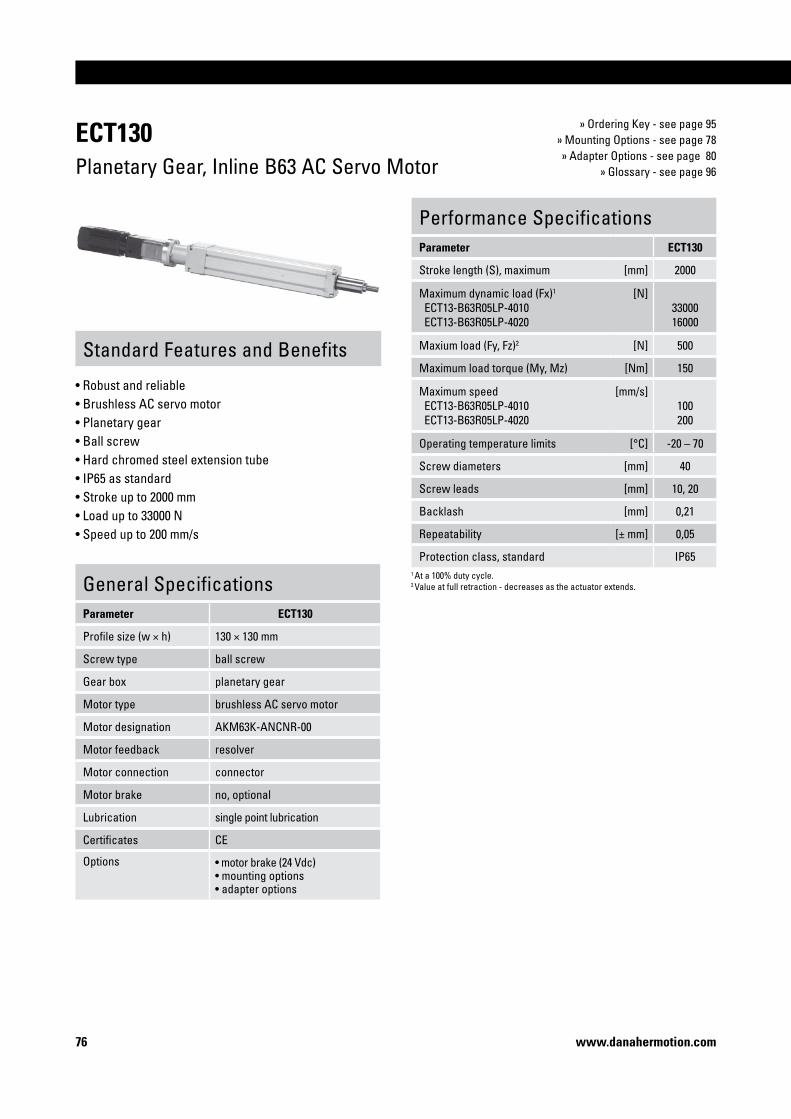
�6 www.danahermotion.com
ECT�30Planetary Gear, Inline B63 AC Servo Motor
» Ordering Key - see page 95» Mounting Options - see page 78» Adapter Options - see page 80
» Glossary - see page 96
Standard Features and Benefits
• Robust and reliable • Brushless AC servo motor• Planetary gear• Ball screw• Hard chromed steel extension tube• IP65 as standard• Stroke up to 2000 mm• Load up to 33000 N• Speed up to 200 mm/s
General SpecificationsParameter ECT�30
Profile size (w × h) 130 × 130 mm
Screw type ball screw
Gear box planetary gear
Motor type brushless AC servo motor
Motor designation AKM63K-ANCNR-00
Motor feedback resolver
Motor connection connector
Motor brake no, optional
Lubrication single point lubrication
Certificates CE
Options • motor brake (24 Vdc)• mounting options• adapter options
Performance SpecificationsParameter ECT�30
Stroke length (S), maximum [mm] 2000
Maximum dynamic load (Fx)1
ECT13-B63R05LP-4010 ECT13-B63R05LP-4020
[N]3300016000
Maxium load (Fy, Fz)2 [N] 500
Maximum load torque (My, Mz) [Nm] 150
Maximum speed ECT13-B63R05LP-4010 ECT13-B63R05LP-4020
[mm/s]100200
Operating temperature limits [°C] -20 – 70
Screw diameters [mm] 40
Screw leads [mm] 10, 20
Backlash [mm] 0,21
Repeatability [± mm] 0,05
Protection class, standard IP651 At a 100% duty cycle. 2 Value at full retraction - decreases as the actuator extends.

Precision Linear Actuators
��www.danahermotion.com
ECT�30Planetary Gear, Inline B63 AC Servo Motor
Performance Diagrams
Critical Speed vs. Stroke
Column Load Limit vs. Stroke
v: speed S: stroke length
1: ECT13-B63R • • LP-40102: ECT13-B63R • • LP-4020
F: load S: stroke length
1: ECT13-B63R • • LP-40102: ECT13-B63R • • LP-4020
Cover tube length (L) [mm] L = S max + 293
Retracted length (L tot) [mm] L tot = S max + 662
Weight of unit [kg] kg = 46,8 + 0,03 × S max
S max: maximum stroke (ordering stroke in mm) A1: power connector A4: with brakeL: cover tube length A2: resolver connector L tot: retracted length A3: without brake
V: speed F: load
1: ECT13-B63R05LP-40102: ECT13-B63R05LP-4020
Speed vs. Load

�8 www.danahermotion.com
ECT SeriesMounting Options
Mounting Holes - Standard Feature
All ECT models have mounting holes as standard except when ordering mounting feet type F, when the holes are used to attach the feet. Note! The distance “B” and “D” for ECT90 units are different depending of the screw diameter of the unit.
A B C D E
ECT90 45 391 / 482 15 1411 / 1672 M12 × 18
ECT130 60 54 23 216 M16 × 281 ECT09- • • • • • • • • 252 ECT09- • • • • • • • • 32
T-slots and T-slot Bolts - Standard Feature
All ECT models have four T-slots, two on the top and two on the bottom, running along the entire profile. Suitable T-slot bolts can be ordered (see second table below).
A B C D
ECT90 6,4 10,5 3,5 4,5
ECT130 10,5 16,5 6,0 9,0
ø D H p/n
ECT90 M6 18 D310 314
ECT90 M6 26 D310 311
ECT130 M10 28 D800 089
Mounting Feet type F
The mounting feet option comes mounted from factory if ordered. Note! The distance “G” for ECT90 units is different depending of the screw diameter of the unit.
A B C D E F G
ECT90 155 125 15 40 20 13 1411 / 1622
ECT130 220 176 22 60 30 17 2161 ECT09- • • • • • • • • 252 ECT09- • • • • • • • • 32

Precision Linear Actuators
�9www.danahermotion.com
Clevis type S
The clevis option comes mounted from factory on the belt gear if ordered. The clevis mounting option can only be ordered on ECT90 and ECT130 units with belt gear.
Clevis type R
ECT SeriesMounting Options
The trunnion option comes mounted from factory if ordered. The position along the profile can however be adjusted freely by the customer.
Trunnion type T
A B C D E F G H
ECT90 70 165 305 155 25 H9 122 147 70
ECT130 73 224 399 200 30 H9 134 159 90
A B C D E F G H I
ECT130 73 224 399 200 30 H9 134 159 90H4 170
The clevis option comes mounted from factory on the belt gear if ordered. The clevis mounting option can only be ordered on ECT130 units with belt gear.
A B C D E F G H
ECT90 150 45 240 20f8 25 75 130 80
ECT130 210 53 316 35f8 30 93 180 110

80 www.danahermotion.com
ECT SeriesAdapter Options
Inside Thread type P and R
Inside Thread type T, V and X
The inside thread option comes mounted from factory if ordered. Inside threads type P and R only fits ECT90 units where P only are possible on units with screw diameter 25 mm and R only are possible on units with screw diameter 32 mm.
Type A B
ECT90 P 22 M16 × 2
ECT90 R 24 M20 × 1,5
The inside thread option comes mounted from factory if ordered. Inside threads type T, V and X only fits ECT130 units.
Type A B
ECT130 T 45 M27 × 2
ECT130 V 45 M33 × 2
ECT130 X 45 M30 × 2

Precision Linear Actuators
8�www.danahermotion.com
ECT SeriesAdapter Options
Outside Thread type N and Q
The outside thread option comes mounted from factory if ordered. Outside threads type N and Q only fits ECT90 units where N only are possible on units with screw diameter 25 mm and Q only are possible on units with screw diameter 32 mm.
Type A B
ECT90 N 32 M16 × 1,5
ECT90 Q 40 M20 × 1,5
Outside Thread type S and U
The outside thread option comes mounted from factory if ordered. Outside threads type S and U only fits ECT130 units.
Type A B C
ECT130 S 54 M27 × 2 66
ECT130 U 45 M33 × 2 57

8� www.danahermotion.com
ECT SeriesAdapter Options
Spherical Joint type J and K
The spherical joint comes mounted from factory if ordered. Joints type J and K only fits ECT90 units.
Type A B C D E F
ECT90 J 76 97 42 16 15 21
ECT90 K 90 115 50 20 18 25

Precision Linear Actuators
83www.danahermotion.com
ECT SeriesAdapter Options
Spherical Joint type L and M
The spherical joint comes mounted from factory if ordered. Joints type L and M only fits ECT130 units. Joint type M includes a grease nipple.
Type A B C D E F
ECT130 L 137 172 70 30 25 37
ECT130 M 115 164 97 40 32 40
Type L
Type M

84 www.danahermotion.com
ECT SeriesSensors Option
Magnetic Sensors Option
The magnetic sensors are mounted directly in the sensor slots on both sides of the profile of the units. They require no additional mounting bracket. The sensor is fixed in position by two M3 size locking screws (A1). The cable (A2) is molded into the sensor. Up to nine normally open and nine normally closed sensors can be ordered to the unit using the ordering key. These sensors will be shipped with the unit but not mounted to the unit. Extra sensors can be ordered using the part numbers.
Technical SpecificationParameter
Max. power [W] 10
Max. voltage [Vdc] 100
Max. current [A] 0,5
LED indicator for switch no
Protection class IP67
Cable length [m] 3
Cable cross section [mm2] 2 × 0,15
Operating temperature limits [°C] -25 – 65
Weight [kg] 0,050
Part NumbersSensor type suitable units p/n
Normally closed ECT90, ECT130 D535 071
Normally open ECT90, ECT130 D535 070 black
blue
black
blue
Precision Linear Actuators
8�www.danahermotion.com
ECT SeriesProtection Options
Environment Protection Option S1
The S1 environment protection option will enhance the units ability to withstand harsh environments where water, acids and basic agents are present. All performance data and the life expectancy is the same as for standard units.
S1 - Wash down protectionTypical places where S1 is used are in slaughter houses, dairy plants, food plants or in any other light wash down application.
Technical SpecificationItem S�
External screws, bolts, nuts and washers
stainless class A2
Extension tube end standard class A2

86 www.danahermotion.com
EC2 - Acme Screw, Parallel 24 Volt DC Motor1 2 3 4 5 6
EC�-D -�0-04A �000 -MF�M -FT�M -PB
�. Model and motor typeEC2-D = EC2 with 24 Vdc DC motor
�. Max. load, speed, screw type and motor style-100-04A = 800 N, 20 mm/s, acme screw, parallel-50-04A = 425 N, 40 mm/s, acme screw, parallel-20-04A = 170 N, 100 mm/s, acme screw, parallel-15-04A = 125 N, 140 mm/s, acme screw, parallel-10-04A = 80 N, 220 mm/s, acme screw, parallel
3. Stroke (S max)• • • • = distance in mm
4. Mounting options-MF1M = front flange-MF2M = rear flange-MF3M = both front and rear flange-MS1 = side end angel brackets-MS2 = mounting feet-MP2 = rear clevis without pivot base-MP3 = rear clevis with pivot base-MS6M = side tapped holes-MT4 = trunnion
�. Adapter options-FT1M = female thread -MT1M = male thread-FS2 = spherical joint-FC2 = clevis
6. Other options �
-PB = IP65 protective bellows
1 Leave position blank if no other option is desired.
Ordering KeysEC2
EC2 - Acme Screw, Inline 24 Volt DC Motor1 2 3 4 5 6
EC�-D -�0L-04A 800 -MT4 -FC�
�. Model and motor typeEC2-D = EC2 with 24 Vdc DC motor
�. Max. load, speed, screw type and motor style-10L-04A = 80 N, 220 mm/s, acme screw, inline
3. Stroke (S max)• • • • = distance in mm
4. Mounting options-MF1M = front flange-MS2 = mounting feet-MS6M = side tapped holes-MT4 = trunnion
�. Adapter options-FT1M = female thread -MT1M = male thread-FS2 = spherical joint-FC2 = clevis
6. Other options �
-PB = IP65 protective bellows
1 Leave position blank if no other option is desired.

Precision Linear Actuators
8�www.danahermotion.com
Ordering KeysEC2
EC2 - Ball Screw, Parallel 24 Volt DC Motor1 2 3 4 5 6
EC�-D -�0-0�B ��0 -MP� -MT�M
�. Model and motor typeEC2-D = EC2 with 24 Vdc DC motor
�. Max. load, speed, screw type and motor style-100-05B = 1330 N, 25 mm/s, ball screw, parallel-50-05B = 670 N, 50 mm/s, ball screw, parallel-100-16B = 420 N, 80 mm/s, ball screw, parallel-20-05B = 280 N, 130 mm/s, ball screw, parallel-50-16B = 200 N, 160 mm/s, ball screw, parallel-15-05B = 200 N, 170 mm/s, ball screw, parallel-10-05B = 140 N, 260 mm/s, ball screw, parallel-20-16B = 80 N, 410 mm/s, ball screw, parallel-15-16B = 60 N, 560 mm/s, ball screw, parallel-10-16B = 40 N, 830 mm/s, ball screw, parallel
3. Stroke (S max)• • • • = distance in mm
4. Mounting options-MF1M = front flange-MF2M = rear flange-MF3M = both front and rear flange-MS1 = side end angel brackets-MS2 = mounting feet-MP2 = rear clevis without pivot base-MP3 = rear clevis with pivot base-MS6M = side tapped holes-MT4 = trunnion
�. Adapter options-FT1M = female thread -MT1M = male thread-FS2 = spherical joint-FC2 = clevis
6. Other options �
-PB = IP65 protective bellows
1 Leave position blank if no other option is desired.
EC2 - Ball Screw, Inline 24 Volt DC Motor1 2 3 4 5 6
EC�-D -�0L-�6B 36� -MS� -FC� -PB
�. Model and motor typeEC2-D = EC2 with 24 Vdc DC motor
�. Max. load, speed, screw type and motor style-10L-05B = 140 N, 260 mm/s, ball screw, inline-10L-16B = 40 N, 820 mm/s, ball screw, inline
3. Stroke (S max)• • • • = distance in mm
4. Mounting options-MF1M = front flange-MS2 = mounting feet-MS6M = side tapped holes-MT4 = trunnion
�. Adapter options-FT1M = female thread -MT1M = male thread-FS2 = spherical joint-FC2 = clevis
6. Other options �
-PB = IP65 protective bellows
1 Leave position blank if no other option is desired.

88 www.danahermotion.com
Ordering KeysEC2
EC2 - Ball Screw, Parallel BK23 AC Servo Motor1 2 3 4 5 6
EC�-BK �3R-�0-�6B �000 -MF3M -FT�M -BM�4
�. Model and motor typeEC2-BK = EC2 with AC servo motor
�. Max. load, speed, screw type and motor style23R-50-05B = 3600 N, 60 mm/s, ball screw, parallel23R-100-16B = 2830 N, 90 mm/s, ball screw, parallel23R-20-05B =1900 N, 290 mm/s, ball screw, parallel23R-50-16B = 1420 N, 180 mm/s, ball screw, parallel23R-15-05B = 1400 N, 390 mm/s, ball screw, parallel23R-10-05B = 950 N, 400 mm/s, ball screw, parallel23R-20-16B = 590 N, 920 mm/s, ball screw, parallel23R-15-16B = 440 N, 1250 mm/s, ball screw, parallel23R-10-16B = 290 N, 1280 mm/s, ball screw, parallel
3. Stroke (S max)• • • • = distance in mm
4. Mounting options-MF1M = front flange-MF2M = rear flange-MF3M = both front and rear flange-MS1 = side end angel brackets-MS2 = mounting feet-MP2 = rear clevis without pivot base-MP3 = rear clevis with pivot base-MS6M = side tapped holes-MT4 = trunnion
�. Adapter options-FT1M = female thread -MT1M = male thread-FS2 = spherical joint-FC2 = clevis
6. Other options �
-BM24 = motor brake-PB = IP65 protective bellows-BM24-PB = brake and IP65 protective bellows
1 Leave position blank for no option
EC2 - Ball Screw, Inline BK23 AC Servo Motor1 2 3 4 5 6
EC�-BK �3R-�0L-0�B 9�0 -MS6M -FS�
�. Model and motor typeEC2-BK = EC2 with AC servo motor
�. Max. load, speed, screw type and motor style23R-10L-05B = 950 N, 400 mm/s, ball screw, inline23R-10L-16B = 290 N, 1280 mm/s, ball screw, inline
3. Stroke (S max)• • • • = distance in mm
4. Mounting options-MF1M = front flange-MS2 = mounting feet-MS6M = side tapped holes-MT4 = trunnion
�. Adapter options-FT1M = female thread -MT1M = male thread-FS2 = spherical joint-FC2 = clevis
6. Other options �
-BM24 = motor brake-PB = IP65 protective bellows-BM24-PB = brake and IP65 protective bellows
1 Leave position blank for no option

Precision Linear Actuators
89www.danahermotion.com
Ordering KeysEC3
EC3 - Ball Screw, Parallel BK23 AC Servo Motor1 2 3 4 5 6
EC3-BK �3R-�0-0�B �000 -MP3 -FC� -PB
�. Model and motor typeEC3-BK = EC3 with AC servo motor
�. Max. load, speed, screw type and motor style23R-70-05B = 5390 N, 35 mm/s, ball screw, parallel23R-50-05B = 3380 N, 50 mm/s, ball screw, parallel23R-70-10B = 2700 N, 70 mm/s, ball screw, parallel23R-20-05B = 1950 N, 260 mm/s, ball screw, parallel23R-50-10B = 1940 N, 100 mm/s, ball screw, parallel23R-15-05B = 1420 N, 260 mm/s, ball screw, parallel23R-50-16B = 1210 N, 160 mm/s, ball screw, parallel23R-10-05B = 950 N, 260 mm/s, ball screw, parallel23R-15-10B = 710 N, 530 mm/s, ball screw, parallel23R-20-16B = 610 N, 890 mm/s, ball screw, parallel23R-10-10B = 480 N, 530 mm/s, ball screw, parallel23R-10-16B = 270 N, 1280 mm/s, ball screw, parallel
3. Stroke (S max)• • • • = distance in mm
4. Mounting options-MF1M = front flange-MF2M = rear flange-MF3M = both front and rear flange-MS1 = side end angel brackets-MS2 = mounting feet-MP2 = rear clevis without pivot base-MP3 = rear clevis with pivot base-MS6M = side tapped holes-MT4 = trunnion
�. Adapter options-FT1M = female thread -MT1M = male thread-FS2 = spherical joint-FC2 = clevis
6. Other options �
-BM24 = motor brake-PB = IP65 protective bellows-BM24-PB = brake and IP65 protective bellows
1 Leave position blank for no option
EC3 - Ball Screw, Inline BK23 AC Servo Motor1 2 3 4 5 6
EC3-BK �3R-�0L-�6B �000 -MS� -FT�M -BM�4
�. Model and motor typeEC3-BK = EC3 with AC servo motor
�. Max. load, speed, screw type and motor style23R-10L-05B = 950 N, 260 mm/s, ball screw, inline32R-10L-16B = 900 N, 1280 mm/s, ball screw, inline23R-10L-10B = 480 N, 530 mm/s, ball screw, inline23R-10L-16B = 270 N, 1280 mm/s, ball screw, inline
3. Stroke (S max)• • • • = distance in mm
4. Mounting options-MF1M = front flange-MS2 = mounting feet-MS6M = side tapped holes-MT4 = trunnion
�. Adapter options-FT1M = female thread -MT1M = male thread-FS2 = spherical joint-FC2 = clevis
6. Other options �
-BM24 = motor brake-PB = IP65 protective bellows-BM24-PB = brake and IP65 protective bellows
1 Leave position blank for no option
EC3 - Ball Screw, Parallel BK32 AC Servo Motor1 2 3 4 5 6
EC3-BK 3�R-�0-�0B �000 -MP3 -FC� -BM�4-PB
�. Model and motor typeEC3-BK = EC3 with AC servo motor
�. Max. load, speed, screw type and motor style32R-50-05B = 7200 N, 50 mm/s, ball screw, parallel32R-70-10B = 7100 N, 70 mm/s, ball screw, parallel32R-50-10B = 5880 N, 100 mm/s, ball screw, parallel32R-15-05B = 4300 N, 260 mm/s, ball screw, parallel32R-50-16B = 3670 N, 160 mm/s, ball screw, parallel32R-15-10B = 2150 N, 530 mm/s, ball screw, parallel32R-15-16B = 1350 N, 870 mm/s, ball screw, parallel32R-10-16B = 900 N, 1280 mm/s, ball screw, parallel
3. Stroke (S max)• • • • = distance in mm
4. Mounting options-MF1M = front flange-MF2M = rear flange-MF3M = both front and rear flange-MS1 = side end angel brackets-MS2 = mounting feet-MP2 = rear clevis without pivot base-MP3 = rear clevis with pivot base-MS6M = side tapped holes-MT4 = trunnion
�. Adapter options-FT1M = female thread -MT1M = male thread-FS2 = spherical joint-FC2 = clevis
6. Other options �
-BM24 = motor brake-PB = IP65 protective bellows-BM24-PB = brake and IP65 protective bellows
1 Leave position blank for no option

90 www.danahermotion.com
Ordering KeysEC4
EC4 - Ball Screw, Parallel BK32 AC Servo Motor1 2 3 4 5 6
EC4-BK 3�R-�00-��B ��00 -MF3M -FT�M -BM�4
�. Model and motor typeEC4-BK = EC2 with AC servo motor
�. Max. load, speed, screw type and motor style32R-100-05B = 12000 N, 27 mm/s, ball screw, parallel32R-50-10B = 7020 N, 50 mm/s, ball screw, parallel32R-100-25B = 5500 N, 65 mm/s, ball screw, parallel32R-20-10B = 2870 N, 410 mm/s, ball screw, parallel32R-50-25B = 2800 N, 130 mm/s, ball screw, parallel32R-15-10B = 2160 N, 530 mm/s, ball screw, parallel32R-20-25B = 1150 N, 1020 mm/s, ball screw, parallel32R-15-25B = 860 N, 1330 mm/s, ball screw, parallel32R-10-25B = 570 N, 1330 mm/s, ball screw, parallel
3. Stroke (S max)• • • • = distance in mm
4. Mounting options-MF1M = front flange-MF2M = rear flange-MF3M = both front and rear flange-MS1 = side end angel brackets-MS2 = mounting feet-MP2 = rear clevis without pivot base-MP3 = rear clevis with pivot base-MS6M = side tapped holes-MT4 = trunnion
�. Adapter options-FT1M = female thread -MT1M = male thread-FS2 = spherical joint-FC2 = clevis
6. Other options �
-BM24 = motor brake-PB = IP65 protective bellows-BM24-PB = brake and IP65 protective bellows
1 Leave position blank for no option
EC4 - Ball Screw, Inline BK32 AC Servo Motor1 2 3 4 5 6
EC4-BK 33R-�0L-��B ���0 -MF�M -FS�
�. Model and motor typeEC4-BK = EC2 with AC servo motor
�. Max. load, speed, screw type and motor style32R-10L-25B = 570 N, 1330 mm/s, ball screw, parallel
3. Stroke (S max)• • • • = distance in mm
4. Mounting options-MF1M = front flange-MS2 = mounting feet-MS6M = side tapped holes-MT4 = trunnion
�. Adapter options-FT1M = female thread -MT1M = male thread-FS2 = spherical joint-FC2 = clevis
6. Other options �
-BM24 = motor brake-PB = IP65 protective bellows-BM24-PB = brake and IP65 protective bellows
1 Leave position blank for no option

Precision Linear Actuators
9�www.danahermotion.com
Ordering KeysEC5
EC5 - Ball Screw, Parallel BK32 AC Servo Motor1 2 3 4 5 6
EC�-BK 3�R-�0-�0B �4�0 -MT4 -FS� -BM�4-PB
�. Model and motor typeEC5-BK = EC3 with AC servo motor
�. Max. load, speed, screw type and motor style32R-100-10B = 13750 N, 26 mm/s, ball screw, parallel32R-50-10B = 7020 N, 52 mm/s, ball screw, parallel32R-100-32B = 4290 N, 85 mm/s, ball screw, parallel32R-20-10B = 2870 N, 390 mm/s, ball screw, parallel32R-50-32B = 2190 N, 170 mm/s, ball screw, parallel32R-15-10B = 2160 N, 390 mm/s, ball screw, parallel32R-20-32B = 900 N, 1310 mm/s, ball screw, parallel32R-15-32B = 670 N, 1330 mm/s, ball screw, parallel32R-10-32B = 450 N, 1330 mm/s, ball screw, parallel
3. Stroke (S max)• • • • = distance in mm
4. Mounting options-MF1M = front flange-MF2M = rear flange-MF3M = both front and rear flange-MS2 = mounting feet-MP2 = rear clevis without pivot base-MP3 = rear clevis with pivot base-MS6M = side tapped holes-MT4 = trunnion
�. Adapter options-FT1M = female thread -MT1M = male thread-FS2 = spherical joint-FC2 = clevis
6. Other options �
-BM24 = motor brake-PB = IP65 protective bellows-BM24-PB = brake and IP65 protective bellows
1 Leave position blank for no option
EC5 - Ball Screw, Inline BK32 or BK42 AC Servo Motor1 2 3 4 5 6
EC�-BK 4�R-�0L-3�B 890 -MS� -MT�M -BM�4
�. Model and motor typeEC5-BK = EC3 with AC servo motor
�. Max. load, speed, screw type and motor style42R-10L-32B =1070 N, 1090 mm/s, ball screw, inline 32R-10L-32B = 450 N, 1330 mm/s, ball screw, inline
3. Stroke (S max)• • • • = distance in mm
4. Mounting options-MF1M = front flange-MS2 = mounting feet-MS6M = side tapped holes-MT4 = trunnion
�. Adapter options-FT1M = female thread -MT1M = male thread-FS2 = spherical joint-FC2 = clevis
6. Other options �
-BM24 = motor brake-PB = IP65 protective bellows-BM24-PB = brake and IP65 protective bellows
1 Leave position blank for no option
EC5 - Ball Screw, Parallel BK42 AC Servo Motor1 2 3 4 5 6
EC�-BK 4�R-�0-3�B �4�0 -MT4 -FS� -PB
�. Model and motor typeEC5-BK = EC3 with AC servo motor
�. Max. load, speed, screw type and motor style42R-100-10B = 25000 N, 26 mm/s, ball screw, parallel42R-50-10B = 16750 N, 52 mm/s, ball screw, parallel42R-100-32B = 10250 N, 85 mm/s, ball screw, parallel42R-20-10B = 6860 N, 170 mm/s, ball screw, parallel42R-15-10B = 5140 N, 220 mm/s, ball screw, parallel42R-20-32B = 2140 N, 545 mm/s, ball screw, parallel42R-15-32B = 1600 N, 725 mm/s, ball screw, parallel42R-10-32B = 1070 N, 1090 mm/s, ball screw, parallel
3. Stroke (S max)• • • • = distance in mm
4. Mounting options-MF1M = front flange-MF2M = rear flange-MF3M = both front and rear flange-MS2 = mounting feet-MP2 = rear clevis with pivot base-MP3 = rear clevis without pivot base-MS6M = side tapped holes-MT4 = trunnion
�. Adapter options-FT1M = female thread -MT1M = male thread-FS2 = spherical joint-FC2 = clevis
6. Other options �
-BM24 = motor brake-PB = IP65 protective bellows-BM24-PB = brake and IP65 protective bellows
1 Leave position blank for no option

9� www.danahermotion.com
Ordering KeysECT90
ECT90 - Parallel IEC90 AC Motor1 2 3 4 5 6 7 8
ECT09-I 09B0�PB���0 -��00 X J 0 � XX
�. Model and motor typeECT09-I = ECT90 with IEC90 three phase AC motor
�. Max. load, speed, gear type, brake and motor style09B03PB2510 = 9750 N, 160 mm/s, belt gear, brake, parallel 1
09B02PB2510 = 6500 N, 240 mm/s, belt gear, brake, parallel 1
09B03PB3220 = 4800 N, 320 mm/s, belt gear, brake, parallel 2
09B02PB3220 = 3100 N, 480 mm/s, belt gear, brake, parallel 2
09B01PB3220 = 1600 N, 960 mm/s, belt gear, brake, parallel 2
09B01PB3232 = 900 N, 1520 mm/s, belt gear, brake, parallel 2
3. Stroke (S max)- • • • • = distance in mm
4. Mounting optionsX = no mounting option S = clevisF = mounting feetT = trunnion
�. Adapter optionsJ = spherical joint ø16 mmK = spherical joint ø20 mmN = outside thread M16 × 1,5P = inside thread M16 × 2Q = outside thread M20 × 1,5R = inside thread M20 × 1,5
6. Magnetic sensors N.C 3
• = number of normally closed sensors (0 - 9)
�. Magnetic sensors N.O 3
• = number of normally open sensors (0 - 9)
8. Protection options 4
XX = standardS1 = wash down protection
1 These models are only compatable with adapter options J, N and P.
2 These models are only compatable with adapter options K, Q and R.
3 The sensors are shipped unmounted with the unit.
4 See page 85 for more information.
ECT90 - Parallel B43 or B53 AC Servo Motor1 2 3 4 5 6 7 8
ECT09-B �3R03PB3��0 -�340 S Q 3 0 S�
�. Model and motor typeECT09-B = ECT90 with AC servo motor
�. Max. load, speed, gear type, brake and motor style53R03PB2510 = 9800 N, 220 mm/s, belt gear, no brake, parallel 1
53R02PB2510 = 8000 N, 330 mm/s, belt gear, no brake, parallel 1
53R03PB3220 = 5900 N, 440 mm/s, belt gear, no brake, parallel 2
43R03PB2510 = 5800 N, 140 mm/s, belt gear, no brake, parallel 1
53R02PB3220 = 3900 N, 670 mm/s, belt gear, no brake, parallel 2
43R02PB2510 = 3800 N, 210 mm/s, belt gear, no brake, parallel 1
43R03PB3220 = 2800 N, 270 mm/s, belt gear, no brake, parallel 2
43R02PB3220 = 1800 N, 420 mm/s, belt gear, no brake, parallel 2
53S03PB2510 = 9800 N, 220 mm/s, belt gear, brake, parallel 1
53S02PB2510 = 8000 N, 330 mm/s, belt gear, brake, parallel 1
53S03PB3220 = 5900 N, 440 mm/s, belt gear, brake, parallel 2
43S03PB2510 = 5800 N, 140 mm/s, belt gear, brake, parallel 1
53S02PB3220 = 3900 N, 670 mm/s, belt gear, brake, parallel 2
43S02PB2510 = 3800 N, 210 mm/s, belt gear, brake, parallel 1
43S03PB3220 = 2800 N, 270 mm/s, belt gear, brake, parallel 2
43S02PB3220 = 1800 N, 420 mm/s, belt gear, brake, parallel 2
3. Stroke (S max)- • • • • = distance in mm
4. Mounting optionsX = no mounting option S = clevisF = mounting feetT = trunnion
�. Adapter optionsJ = spherical joint ø16 mmK = spherical joint ø20 mmN = outside thread M16 × 1,5P = inside thread M16 × 2Q = outside thread M20 × 1,5R = inside thread M20 × 1,5
6. Magnetic sensors N.C 3
• = number of normally closed sensors (0 - 9)
�. Magnetic sensors N.O 3
• = number of normally open sensors (0 - 9)
8. Protection options 4
XX = standardS1 = wash down protection
1 These models are only compatable with adapter options J, N and P.
2 These models are only compatable with adapter options K, Q and R.
3 The sensors are shipped unmounted with the unit.
4 See page 85 for more information.

Precision Linear Actuators
93www.danahermotion.com
Ordering KeysECT90
ECT90 - Direct Drive, Inline B43 or B53 AC Servo Motor1 2 3 4 5 6 7 8
ECT09-B �3R0�LD���0 -0800 T P 0 0 S�
�. Model and motor typeECT09-B = ECT90 with AC servo motor
�. Max. load, speed, gear type, brake and motor style53R01LD2510 = 5300 N, 450 mm/s, direct drive, no brake, inline 1
53R01LD3220 = 2600 N, 1000 mm/s, direct drive, no brake, inline 2
43R01LD2510 = 2000 N, 410 mm/s, direct drive, no brake, inline 1
53R03LD3232 = 1500 N, 1600 mm/s, direct drive, no brake, inline 2
43R01LD3220 = 900 N, 820 mm/s, direct drive, no brake, inline 2
53S01LD2510 = 5300 N, 450 mm/s, direct drive, brake, inline 1
53S01LD3220 = 2600 N, 1000 mm/s, direct drive, brake, inline 2
43S01LD2510 = 2000 N, 410 mm/s, direct drive, brake, inline 1
53S03LD3232 = 1500 N, 1600 mm/s, direct drive, brake, inline 2
43S01LD3220 = 900 N, 820 mm/s, direct drive, brake, inline 2
3. Stroke (S max)- • • • • = distance in mm
4. Mounting optionsX = no mounting option F = mounting feetT = trunnion
�. Adapter optionsJ = spherical joint ø16 mmK = spherical joint ø20 mmN = outside thread M16 × 1,5P = inside thread M16 × 2Q = outside thread M20 × 1,5R = inside thread M20 × 1,5
6. Magnetic sensors N.C 3
• = number of normally closed sensors (0 - 9)
�. Magnetic sensors N.O 3
• = number of normally open sensors (0 - 9)
8. Protection options 4
XX = standardS1 = wash down protection
1 These models are only compatable with adapter options J, N and P.
2 These models are only compatable with adapter options K, Q and R.
3 The sensors are shipped unmounted with the unit.
4 See page 85 for more information.
ECT90 - Planetary Gear, Inline B43 or B53 AC Servo Motor1 2 3 4 5 6 7 8
ECT09-B 43R�0LP3��0 -��0� X R 9 � XX
�. Model and motor typeECT09-B = ECT90 with AC servo motor
�. Max. load, speed, gear type, brake and motor style53R10LP3220 = 20000 N, 130 mm/s, planetary gear, no brake, inline53R05LP2510 = 13000 N, 270 mm/s, planetary gear, no brake, inline43R10LP3220 = 10000 N, 80 mm/s, planetary gear, no brake, inline43R05LP3220 = 5000 N, 160 mm/s, planetary gear, no brake, inline53S10LP3220 = 20000 N, 130 mm/s, planetary gear, brake, inline53S05LP2510 = 13000 N, 270 mm/s, planetary gear, brake, inline43S10LP3220 = 10000 N, 80 mm/s, planetary gear, brake, inline43S05LP3220 = 5000 N, 160 mm/s, planetary gear, brake, inline
3. Stroke (S max)- • • • • = distance in mm
4. Mounting optionsX = no mounting option F = mounting feetT = trunnion
�. Adapter optionsK = spherical joint ø20 mmQ = outside thread M20 × 1,5R = inside thread M20 × 1,5
6. Magnetic sensors N.C �
• = number of normally closed sensors (0 - 9)
�. Magnetic sensors N.O �
• = number of normally open sensors (0 - 9)
8. Protection options �
XX = standardS1 = wash down protection
1 The sensors are shipped unmounted with the unit.
2 See page 85 for more information.

94 www.danahermotion.com
Ordering KeysECT130
ECT130 - Parallel IEC100 AC Motor1 2 3 4 5 6 7 8
ECT�3-I �0B03PB40�0 -�8�0 R V � 0 S�
�. Model and motor typeECT13-I = ECT130 with IEC100 three phase AC motor
�. Max. load, speed, gear type, brake and motor style10B03PB4010 = 13300 N, 175 mm/s, belt gear, brake, parallel10B02PB4010 = 9400 N, 210 mm/s, belt gear, brake, parallel10B03PB4020 = 6200 N, 300 mm/s, belt gear, brake, parallel10B02PB4020 = 4200 N, 420 mm/s, belt gear, brake, parallel10B01PB4020 = 1800 N, 950 mm/s, belt gear, brake, parallel10B01PB4040 = 600 N, 1900 mm/s, belt gear, brake, parallel
3. Stroke (S max)- • • • • = distance in mm
4. Mounting optionsX = no mounting option R = clevis F = mounting feetT = trunnion
�. Adapter optionsL = spherical joint ø30 mmM = spherical joint ø40 mmS = outside thread M27 × 2T = inside thread M27 × 2U = outside thread M33 × 2V = inside thread M33 × 2X = inside thread M30 × 2
6. Magnetic sensors N.C �
• = number of normally closed sensors (0 - 9)
�. Magnetic sensors N.O �
• = number of normally open sensors (0 - 9)
8. Protection options �
XX = standardS1 = wash down protection
1 The sensors are shipped unmounted with the unit.
2 See page 85 for more information.
ECT130 - Parallel B53 or B63 AC Servo Motor1 2 3 4 5 6 7 8
ECT�3-B �3R0�PB40�0 -�000 X U 0 0 XX
�. Model and motor typeECT13-B = ECT130 with AC servo motor
�. Max. load, speed, gear type, brake and motor style63R03PB4010 = 21500 N, 160 mm/s, belt gear, no brake, parallel 63R02PB4010 = 15500 N, 220 mm/s, belt gear, no brake, parallel53R03PB4010 = 15000 N, 160 mm/s, belt gear, no brake, parallel 63R03PB4020 = 10500 N, 320 mm/s, belt gear, no brake, parallel53R02PB4010 = 10500 N, 220 mm/s, belt gear, no brake, parallel63R02PB4020 = 7500 N, 440 mm/s, belt gear, no brake, parallel53R03PB4020 = 7000 N, 320 mm/s, belt gear, no brake, parallel53R02PB4020 = 5000 N, 440 mm/s, belt gear, no brake, parallel63S03PB4010 = 21500 N, 160 mm/s, belt gear, brake, parallel 63S02PB4010 = 15500 N, 220 mm/s, belt gear, brake, parallel53S03PB4010 = 15000 N, 160 mm/s, belt gear, brake, parallel 63S03PB4020 = 10500 N, 320 mm/s, belt gear, brake, parallel53S02PB4010 = 10500 N, 220 mm/s, belt gear, brake, parallel63S02PB4020 = 7500 N, 440 mm/s, belt gear, brake, parallel53S03PB4020 = 7000 N, 320 mm/s, belt gear, brake, parallel53S02PB4020 = 5000 N, 440 mm/s, belt gear, brake, parallel
3. Stroke (S max)- • • • • = distance in mm
4. Mounting optionsX = no mounting option R = clevisF = mounting feetT = trunnion
�. Adapter optionsL = spherical joint ø30 mmM = spherical joint ø40 mmS = outside thread M27 × 2T = inside thread M27 × 2U = outside thread M33 × 2V = inside thread M33 × 2X = inside thread M30 × 2
6. Magnetic sensors N.C �
• = number of normally closed sensors (0 - 9)
�. Magnetic sensors N.O �
• = number of normally open sensors (0 - 9)
8. Protection options �
XX = standardS1 = wash down protection
1 The sensors are shipped unmounted with the unit.
2 See page 85 for more information.
Precision Linear Actuators
9�www.danahermotion.com
Ordering KeysECT130
ECT130 - Direct Drive, Inline B53 or B63 AC Servo Motor1 2 3 4 5 6 7 8
ECT�3-B �3R0�LD4040 -�8�0 X S � � S�
�. Model and motor typeECT13-B = ECT130 with AC servo motor
�. Max. load, speed, gear type, brake and motor style63R01LD4010 = 7400 N, 400 mm/s, direct drive, no brake, inline53R01LD4010 = 4900 N, 400 mm/s, direct drive, no brake, inline63R01LD4020 = 3400 N, 1000 mm/s, direct drive, no brake, inline53R01LD4020 = 2250 N, 1000 mm/s, direct drive, no brake, inline63R01LD4040 = 1400 N, 2000 mm/s, direct drive, no brake, inline53R01LD4040 = 700 N, 2000 mm/s, direct drive, no brake, inline63S01LD4010 = 7400 N, 400 mm/s, direct drive, brake, inline53S01LD4010 = 4900 N, 400 mm/s, direct drive, brake, inline63S01LD4020 = 3400 N, 1000 mm/s, direct drive, brake, inline53S01LD4020 = 2250 N, 1000 mm/s, direct drive, brake, inline63S01LD4040 = 1400 N, 2000 mm/s, direct drive, brake, inline53S01LD4040 = 700 N, 2000 mm/s, direct drive, brake, inline
3. Stroke (S max)- • • • • = distance in mm
4. Mounting optionsX = no mounting option F = mounting feetT = trunnion
�. Adapter optionsL = spherical joint ø30 mmM = spherical joint ø40 mmS = outside thread M27 × 2T = inside thread M27 × 2U = outside thread M33 × 2V = inside thread M33 × 2X = inside thread M30 × 2
6. Magnetic sensors N.C �
• = number of normally closed sensors (0 - 9)
�. Magnetic sensors N.O �
• = number of normally open sensors (0 - 9)
8. Protection options �
XX = standardS1 = wash down protection
1 The sensors are shipped unmounted with the unit.
2 See page 85 for more information.
ECT130 - Planetary Gear, Inline B53 or B63 AC Servo Motor1 2 3 4 5 6 7 8
ECT�3-B 63R0�LP40�0 -0600 F L 0 � XX
�. Model and motor typeECT13-B = ECT130 with AC servo motor
�. Max. load, speed, gear type, brake and motor style53R10LP4010 = 38000 N, 50 mm/s, planetary gear, no brake, inline63R05LP4010 = 33000 N, 100 mm/s, planetary gear, no brake, inline53R05LP4010 = 22500 N, 100 mm/s, planetary gear, no brake, inline63R05LP4020 = 16000 N, 200 mm/s, planetary gear, no brake, inline53R05LP4020 = 11000 N, 200 mm/s, planetary gear, no brake, inline53S10LP4010 = 38000 N, 50 mm/s, planetary gear, brake, inline63S05LP4010 = 33000 N, 100 mm/s, planetary gear, brake, inline53S05LP4010 = 22500 N, 100 mm/s, planetary gear, brake, inline63S05LP4020 = 16000 N, 200 mm/s, planetary gear, brake, inline53S05LP4020 = 11000 N, 200 mm/s, planetary gear, brake, inline
3. Stroke (S max)- • • • • = distance in mm
4. Mounting optionsX = no mounting option F = mounting feetT = trunnion
�. Adapter optionsL = spherical joint ø30 mmM = spherical joint ø40 mmS = outside thread M27 × 2T = inside thread M27 × 2U = outside thread M33 × 2V = inside thread M33 × 2X = inside thread M30 × 2
6. Magnetic sensors N.C �
• = number of normally closed sensors (0 - 9)
�. Magnetic sensors N.O �
• = number of normally open sensors (0 - 9)
8. Protection options �
XX = standardS1 = wash down protection
1 The sensors are shipped unmounted with the unit.
2 See page 85 for more information.

96 www.danahermotion.com
AccelerationAcceleration is a measure of the rate of speed change going from standstill (or a lower speed) to a higher speed. The calculations, which are used to develop the Load versus Speed diagrams for each actuator, are based on an acceleration rate that is limited by the maximum speed of the unit. Therefore, this value will be different for all actuators. Please contact customer service if your application is critical to which acceleration rate is acceptable or needed. Also see “Deceleration”.
AccuracyThere are several types of accuracy and many different factors that will affect the overall accuracy of a system. Also see “Repeatability”, “Positioning Accuracy”, “Resolution”, “Lead Accuracy” and “Backlash”.
Acme ScrewThe advantages of acme screws (fig. a) are that they withstand vibrations and shock loads better than ball screws. However, they are louder, less accurate, and limited to 50% duty cycle (catalog standard). Also see “Lead Screws” and “Duty Cycle”.
Fig. a
AC Motor There are several types of AC motors; all of which run on an applied alternating current. Also see “Three Phase AC Motor”.
AC Servo Motor AC servo motor is an abbreviation for a brushless, synchronous AC motor design. This type of design requires little mechanical maintenance since no physical contact (no brushes and bars) is used to commutate the motor. This extends the life of the motor and reduces down time. Also see “Brushless AC Servo Motor”.
AdapterThe adapter on EC and ECT actuators is the connection point for the load and is situated at the end of the extension tube. There are several types of adapters: 1) tapped hole, 2) threaded rod, 3) spherical joint, and 4) clevis with a pin. Also see “Mounting”.
Anti Rotation MechanismAn actuator with anti-rotation mechanism has a built-in feature that prevent the extension tube from rotating if the tube is not attached to any load. All EC and ECT actuators have this feature.
BacklashBacklash is the stack up of tolerances (play) within the leadscrew assembly and gearing which creates a dead band when changing directions. The result is that the motor can rotate some before any motion can be seen on the extension tube when reversing the direction of the motor rotation. The backlash varies depending of the actuator model and the amount of backlash for each can be found in the performance specifications. The backlash for ball screw models will remain the same during its life time while it will increase slightly for acme screws. Direct driven models normally have less backlash because the do not incorporate any gearing.
Ball ScrewBall screws (fig. b) are highly efficient and are used for high loads and speeds. In comparison to acme screws, they are more accurate and can run up at 100% duty cycle. However, they produce a bit more noise. Also see “Lead Screw” and “Duty Cycle”.
Fig. b
Belt GearA belt gear consist of a timing belt that runs between two pulley wheels of different diameter. The difference between the diameters determines the gear ratio. Belt gears are quiet, have medium accuracy, and require no maintenance. But the belt is susceptible to breakage under overload conditions
BrakeAcme screws are inherently self-locking while ball screws are not. To prevent ball screw actuators from backdriving, the actuator may need some type of motor brake depending on the application. A brake can also be used to stop the actuator quickly and safely in emergency situations. Precision linear actuators with DC motors do not have optional brakes so an alternative solution must be sought. All asynchronous three-phase AC motors come equipped with an electrically released, fail-safe brake (optional for brushless AC servo motors).
GlossaryA – Bra

Precision Linear Actuators
9�www.danahermotion.com
Breather Tube OutputA fitting is included, which can be installed to the breather tube output to permit the actuator to breathe through a tube from a non-contaminated area, or receive a continuous positive pressure of 14 - 20 kPa (2 - 3 psi) dry air.
Brushless AC Servo Motor A brushless AC servo motor has many advantages over DC and asynchronous three-phase AC motors. For a given power rating, they are smaller and can typically travel at higher speeds and acceleration rates (due to a lower rotor inertia). Unlike DC motors, AC servo motors have no brushes for commutation; therefore, they are almost maintenance free. Instead, they incorporate a resolver feedback device that feeds a shaft-position signal to the drive control for commutation. The drive control also converts the resolver signal into a simulated encoder pulse train that can be used to feed a positioning controller. Also see “Premanent Magnet DC Motor”, “ Three Phase AC motor”,“Servo Motor” and “Servo Drive”.
CertificatesAll actuators sold in the EU are CE certified. Please contact customer service if you need any other type of certificate.
Column Load LimitThe column load limit is the maximum compression force that the lead screw can handle before it becomes damaged (Fig. c). The limit is a function of the the screw diameter and the unsupported length of the screw which means that the limit will drop as the extension tube extends. For some actuators this means that the allowed maximum dynamic load found in the performance specifications can be higher than the column load limit when the extension tube travel is beyond a certain distance. In this case, either the load must be reduced to the column load limit, the amount of used stroke must be reduced, or you must select another actuator model that can manage the column load at that stroke. The column load force limits can be found in the “Column Load vs. Stroke” diagram on the product pages for each actuator. Also see “Dynamic Load Rating”.
Fig. c
ThrustLoad
Compression (column) Load
ControlsThere are many types of programmable controls that can be used to control the motion of the actuator. PLC’s, motion controls, robot controls, CNC controls and industrial computers are just some of them. Many types of servo drives have built-in (or as an expansion card option) programmable motion control features. Danaher Motion offers a variety of combinations to serve your motion control needs.
Cover TubeThe cover tube provides protection for the ball or acme screw and provides protection and support for the extension tube. The cover tube on EC and ECT actuators are designed so that magnetic sensors easily can be mounted to the outside of the tube. Also see “Extension Tube” and “Magnetic Sensors”.
Critical SpeedAll lead screws have a critical speed where the screw starts to vibrate and eventually bend or warp the screw (Fig. d). The excact limit is a function of how far out the extension tube is run and speed. For some actuators this means that the allowed maximum speed found in the performance specifications can be higher than the critical speed when the extension tube travel is beyond a certain distance. In this case, either the speed must be reduced to the critical speed, the amount of stroke must be reduced, or you must select another actuator model that can manage the speed at that stroke. The critical speed limits can be found in the “Critical Speed vs. Stroke” diagram on the product pages for each actuator. Also see “Speed Rating”.
Fig. dL
CustomizationEven the most versatile standard actuator may not always suit all applications. But whatever your need is, our engineers are ready to help you to customize the actuators according to your requirements. We build more exclusive actuators than anyone in the bussines and have decades of experience in customizing actuators to meet special needs.
CycleOne cycle is one complete extension and retraction of the extension tube.
GlossaryBre – C

98 www.danahermotion.com
EncoderEncoders provide a digital output signal in the form of a square shaped pulse train that can be used to determine the position of the extension tube. The encoder signal in a servo motor system is connected to the motion control so that it can control the servo drive and hence close the position feedback loop. The servo motors used on the precision linear actuators do not have an encoder. Instead, they incorporate a resolver feedback device that feeds a shaft-position signal to the drive control. The drive control also converts the resolver signal into a simulated encoder pulse train that can be used to feed a positioning controller. Also see “Resolver”, Servo Motor” and Servo Drive”.
End of Stroke SwitchesWe strongly recommend the use of switches at the ends of the actuator stroke to prevent the unit from running in to the mechanical end stops. Keep in mind that the extension tube will travel some distance (dependant of speed, load and actuator type) before it comes to a complete stop. This means the end of stroke switches must be placed before the mechanical end of stroke and will reduce the available stroke length.
Extension TubeThe extension tube slides in and out of the actuator‘s cover tube and is connected via the front adaptor to the load being moved or positioned. Also see “Cover Tube”.
Extension Tube Side LoadThe extension tube side loads (Fy and Fz) are the forces applied to the sides of the extension tube. The maximum allowed side loads can be found in the performance specifications for each actuator. The stated side loads are only valid for a completely retracted extension tube and will decrease as the extension tube extends. Also see “Forces”.
ForcesThe below figure (Fig. e) show the definitions for the forces and moments used in this catalog. Always use these definitions in any communication with Danaher Motion.
Fig. e
GlossaryD – Fo
DecelerationDeceleration is a measure of the rate of speed change going from a higher speed to a lower speed (or standstill). The calculations, which are used to develop the Load versus Speed diagrams for each actuator, are based on a deceleration rate that is limited by the maximum speed of the unit. Therefore, this value will be different for all actuators. Please contact customer service if your application is critical to which deceleration rate is acceptable or needed. Also see “Acceleration”.
DC MotorThere are several types of DC motors which all have in common that they run on direct current. A DC motor has several advantages. It is lower in cost then most AC alternatives and is fairly easy and inexpensive to control. However, they are typically bulky and experience brush wear, leading to higher maintenance cost and down time. Also see “Brushless AC Servo Motor”, “Three Phase AC motor”,“Servo Motor” and “Servo Drive”.
Direct DriveDirect drive means that there is no gearing between the motor and the lead screw. Instead the motor is connected to the lead screw directly via a coupling.
Duty Cycle on time Duty cycle = (on time + off time)
Example: 2,5 minutes on, 7,5 minutes off
2,5 min
(2,5 min + 7,5 min) = 25% duty cycle
The duty cycle is a function of the load and the ambient temperature. A higher ambient temperature and/or load will affect the duty cycle negatively while a lower temperature and/or lower load will affect it positively. The duty cycles stated in this catalog are all valid for a 10 minute period.
Dynamic Load RatingThe dynamic load rating (Fx) is the maximum load the actuator can move at a given speed. The relation between the the dynamic load and the speed can be studied in the speed versus load diagrams. For some actuators however, the column load limit will be exceeded if the extension tube extends beyond a certain point. Also see “Load Rating” “Forces” and “Column Load Limit”.
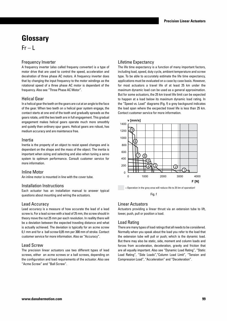
Precision Linear Actuators
99www.danahermotion.com
Frequency InverterA frequency inverter (also called frequeny converter) is a type of motor drive that are used to control the speed, acceleration and decelration of three phase AC motors. A frequency inverter does that by changing the input frequency to the motor windings as the rotational speed of a three phase AC motor is dependant of the frequency. Also see “Three Phase AC Motor”.
Helical GearIn a helical gear the teeth on the gears are cut at an angle to the face of the gear. When two teeth on a helical gear system engage, the contact starts at one end of the tooth and gradually spreads as the gears rotate, until the two teeth are in full engagement. This gradual engagement makes helical gears operate much more smoothly and quietly than ordinary spur gears. Helical gears are robust, has medium accuracy and are maintenace free.
InertiaInertia is the property of an object to resist speed changes and is dependant on the shape and the mass of the object. The inertia is important when sizing and selecting and also when tuning a servo system to optimum performance. Consult customer service for more information.
Inline MotorAn inline motor is mounted in line with the cover tube.
Installation InstructionsEach actuator has an installation manual to answer typical questions about mounting and wiring the actuators.
Lead AccuracyLead accuracy is a measure of how accurate the lead of a lead screw is. For a lead screw with a lead of 25 mm, the screw should in theory move the nut 25 mm per each revolution. In reallity there will be a deviation between the expected traveling distance and what is actually achieved. The deviation is typically for an acme screw 0,1 mm and for a ball screw 0,05 mm per 300 mm of stroke. Contact customer service for more information. Also se “Accuracy”.
Lead ScrewThe precision linear actuators use two different types of lead screws, either an acme screws or a ball screws, depending on the configuration and load requirements of the actuator. Also see “Acme Screw” and “Ball Screw”.
GlossaryFr – L
Lifetime ExpectancyThe life time expectancy is a function of many important factors, including load, speed, duty cycle, ambient temperature and screw type. To be able to accurately estimate the life time expectancy, applications must be evaluated on a case by case basis. However, for most actuators a travel life of at least 25 km under the maximum dynamic load can be used as a general approximation. But for some actuators, the 25 km travel life limit can be expected to happen at a load below its maximum dynamic load rating. In the “Speed vs. Load” diagrams (Fig. f) a grey backgound indicates the load span where the excpected travel life is less than 25 km. Contact customer service for more information.
= Operation in the grey area will reduce life to 25 km of operation!
Fig. f
Linear ActuatorsActuators providing a linear thrust via an extension tube to lift, lower, push, pull or position a load.
Load RatingThere are many types of load ratings that all needs to be considered. Normally when you speak about the load you refer to the load that the extension tube will pull or push; which is the dynamic load. But there may also be static, side, moment and column loads and forces from acceleration, deceleration, gravity and friction that are all equally important. Also see “Dynamic Load Rating”, “Static Load Rating”, “Side Loads”,“Column Load Limit”, “Tension and Compression Load”, “Acceleration” and “Deceleration”.

�00 www.danahermotion.com
GlossaryM – Po
Mounting OptionsTo be able to mount a precision linear actuator you must select the appropiate mounting and adapter options for your application. There are several different options to choose from and you can define your choice by using the ordering keys. For ECT actuators, you always have mounting holes and T-slots as a default mounting method. With EC units, you always must select a mounting option to be able to mount it. Also see “Mounting” and “Adapter”.
Operating and Storage TemperatureThe operating temperature is the range in which the actuator may be safely operated. All actuators can be stored or transported at the same temperature as the operating temperature. Contact customer support if the operating temperature will be exceeded during storage or transportation.
Parallel MotorA parallel motor is mounted parallel to the cover tube.
Permanent Magnet DC MotorA permanent magnet DC motor has a permanent magnet in the stator while the windings are in the rotor. The commutation of the current to the rotor windings is done through two brushes. The advantages with this type of motor is that it is fairly easy to control and has a lower cost compared to a brushless AC servo motor. The disadvantages compared to brushless AC servo motor are the maintenance required (the brushes needs to replaced as they wear) and a larger size for a given power rating. The DC motor is also less responsive due to the added inertia having the windings on the rotor.
Planetary Gear A planetary gear is a gear system that consists of one or more outer gears (planet gears) rotating about a central (sun) gear. Typically, the planet gears are mounted on a movable arm or carrier which itself may rotate relative to the sun gear. As a result, planetary gears have the input and output shaft in line with each other with rotation in the same direction. Planetary gears are robust, accurate and comparably small but are more expensive than belt or helical gears.
Positioning accuracy Positioning accuracy is the error between the the expected and actual position and is the sum of all factors that will reduce the accuracy (i.e. repeatability, backlash, resolution, lead accuracy, and the accuracy of the motor, drive and motion control system). Some of these factors, such as backlash and lead accuracy, can sometimes be compensated for in the software of the motion control system being used. Also see “Accuracy”.
Magnetic SensorsThe magnetic sensors used to the precision linear actuators consist of a reed switch that are molded into a plastic housing. In the actuator a magnet is mounted that travels back and forth with the extension tube. The magnet triggers the magnetic sensors which are mounted on the outside of the cover tube. The sensors come in both normally open and normally closed versions.
Motion ControlA motion control is a control that is dedicated to control the motion of a servo motor. To be able to do this the control must have inputs that can recieve the feedback signal which typically is an encoder signal (even if other devices such as potentiometers and resolvers, can be used) and an output which gives the motion commands to the servo drive. Motion controls can be stand alone units or be integrated in other control systems. Also see “Control”, “Servo Motors and “Servo Drive”.
Motor TypeThere are three types of electrical motors in different sizes used on the precision linear actuators; DC motors, three phase AC motors and brushless AC servo motors. Also see “Permanent Magnet DC motor”, Brushless AC Servo Motor” and “Three Phase AC motor”.
MountingThe precision linear actuators can quickly and easily be mounted using any of the available mounting and adapter options. There are however some things to consider when mounting the actuator. When using the clevis type of mounting, solid mounting pins should be used (avoid using roll or spring type mounting pins). The mounting pins (or trunnions) should be parallel to each other as shown below (Fig. g). It is also recommended to attach the load so that the force act along the axis of the actuator (Fig. h). Any actuator using side angel brackets, tapped holes or mounting feet should be mounted so that the covertube or the extension tube not becomes bend or is subjected to bending forces during standstill or operation.
Fig. g Fig. h

Precision Linear Actuators
�0�www.danahermotion.com
GlossaryPr – Sp
Protection ClassThe protection class refers to the environmental rating of the enclosure. The first digit applies to airborne contaminants and the second digit to water/moisture. IP54: protected from dust and splashing water from any direction.IP65: dust tight and protected against low pressure water jets from any direction.
RepeatabilityRepeatability is the ability for a positioning system to return to a location when approaching from the same distance, at the same speed and deceleration rate. Some of the factors that affect the repatability are the angular repeatability of the motor, drive and motion control system, system friction and changes in load, speed and deceleration.
ResolutionResolution is the smallest move increment that the system can perform. Some of the factors that affect the resolution are the angular repeatability of the motor, drive and motion control system, system friction, the drive train reduction, the type and lead of the lead screw and changes in load, speed and deceleration.
ResolverA resolver is basically a type of rotary electrical transformer used for measuring degrees of rotation and are commonly used on AC servo motors as a feedback device to control the commutation of the motor windings. The resolver is mounted to the end of motor shaft and when the motor rotates the resolver will transmit the position and direction of the rotor to the servo drive which then can control the motor. Most servo drives for AC servo motors on the market today can convert the resolver signal in to a pulse train (encoder signal simulation) which can be used by a motion control to determine and control the position of the motor. Also see “Encoder”, “Servo Drive”, “Servo Motor” and “Motion Control”.
RoHS ComplianceThe RoHS directive stands for “the restriction of the use of certain hazardous substances in electrical and electronic equipment”. This directive bans the placing on the EU market of new electrical and electronic equipment containing more than agreed levels of lead, cadmium, mercury, hexavalent chromium, polybrominated biphenyl (PBB) and polybrominated diphenyl ether (PBDE) flame retardants. All precicion linear actuators, controls and accesso-ries sold in the EU are RoHS compliant.
Service and MaintenancePrecision liner actuators only need to be lubricated. The intervall between the lubrications depends on the how frequent and hard the actuator works. The lubrication of the entire actuator is done at one single point. No other service or maintenance is required.
Servo DriveA servo drive is an electrical device which controls the commutation of a servo motor. Different types of servo motors require different types of drives. To be able to run the system as a servo system there must also be a motion control which give the commands to the servo drive and some kind of feedback (encoder, potentiometer, etc) to the control so that it can determine and adjust the speed and the position of the motor (closed loop feedback). Some servo drives has built in motion controls. Also see “Servo Motor”, Brushless AC Servo Motor” and “Controls”.
Servo MotorA servo motor is a motor that works with a feedback device in a closed loop configuration controlled by a motion control. Any type of motor can in principal work as a servo motor but normally when speaking about servo motors you refer to motors that are specially designed to work in servo systems. Also see “Servo Drive”, Brushless AC Servo Motor” and “Controls”.
Side LoadsSee “Extension Tube Side Loads”.
Sizing and SelectionThis catalog can give you an overview of what Danaher Motion can offer you and an indication of which products that may suit your application. But in order to get the best solution for your it is neccessary to know your specific application and to carry out detailed sizing and selection calculations. Please contact customer service for further help.
Speed RatingThe speed versus load diagrams on each product page show the maximum allowed speed at any given dynamic load ranging from no load to maximum allowed dynamic load. For some actuators however, the critical speed limit can be a limiting factor for the maximum allowed speed if the extension tube extends beyond a certain point. Also see “Load Rating” “Forces” and “Critical Speed Limit”.

�0� www.danahermotion.com
Static Load RatingThe static load rating is how much load the actuator will hold at standstill. This value can be higher than the dynamic load ratingand depends on factors such as stroke length, column load rating, gear type, and maximum holding force of the motor brake. Consult customer service for more information. Also see “Load Rating”.
Stroke LengthThe maximum stroke length for each actuator type can be found in the performance specifications. The stroke length is the available distance the extension tube can move from one mechanical end to the other. Keep in mind that extra stroke length above the application requirements will be needed to avoid hitting the mechanical end stops. We also recommend the use of end of stroke limit switches (both extension and retraction) to avoiding running in to the mechanical ends by accident. Using end of stroke limit switches require some deceleration distance to be added to the stroke so that the extension tube has time to stop before running in to the ends. Exactly how much extra stroke you need depends on many factors and needs to be determined for each application on a case to case basis. Also see “End of Stroke Limit Switches”.
Tension and Compression LoadA tension load tries to stretch the actuator and a compression load tries to compress the actuator (Fig. i). All precision linear actuators can manage the same tension and compression load. Also see “Dynamic Load Rating”.
Fig. i
Load
Load
GlossarySt – T
Three Phase AC Motor The three phase AC motor is known under many names; squirrel cage motor, induction motor, asynchronous motor or asynchronous induction motor are a few. The three phase AC motor can be run directly from a three phase source in which case its speed will be determined by the frequency and the number of poles. The typical nominal speed of a 2 pole motor is around 2850 rpm, a 4 pole has half that speed and a 8 pole half of the 4 pole, etc. However, when running the motor directly from a three phase source there is no control of the speed, acceleration or deceleration. Instead, the motor accelerates as fast as it can, depending of the load, to its nominal speed. This puts stress on the mechanical components, if they can manage it at all. A precision linear unit with a three phase AC motor is not designed to run directly from a three phase source. Instead, a frequency inverter must be used that can control speed, acceleration and deceleration to keep these within the acceptable limits. A three phase motor is relatively cheap, very robust and needs no maintenance. The downside is that even though it can be controlled from a frequency inverter, it will never be as accurate as a servo motor system. Especially at low speeds (below approximately 10 Hz), the motor will start to loose torque and may also become overheated with time, as the internal fan mounted on the rotor will rotate too slow to be able to cool the motor sufficient for operation. Using an external fan mounted to the back of the motor may solve this problem but is an added cost and will also make the installation larger. The speed at which overheating caution should be taken is marked in the “Speed vs. Load” diagrams with a dashed line instead of a continous line (Fig. h). Also see “Frequency Inverter” and “Motor Type”.
Fig. h

Precision Linear Actuators
�03www.danahermotion.com
Application Data Form*Submitted by: Phone: Date:
1. Company name 20. Do you need any special retracted length (cross hole c/c in mm)?
2. Street address 21. What kind of motor would you prefer?
3. City-state, zip 22. Is a holding brake required?
4. Contact name 23. Do you need any of the optional features of the actuator?
5. Phone 24. Do you need a matching drive to the actuator?
6. Fax 25. What is the accuracy requirements of the application?
7. E-mail 26. What are the environmental conditions (dusty, outdoors, wash down)?
8. What is the estimated annual volume? 27. What is the operation temperature range in Celcius?
9. What is the target price? 28. What is the duty cycle (on-time / on-time + off-time) in seconds?
10. What is the current or alternative solution? 29. Do you need any certificate (UL, CE, etc.)?
11. How much load is moved in Newton? 30. Do you require any print (dwg, dxf, faxed)?
12. How much load do you need to hold in Newton? 31. Describe any additional requirements (packaging, labeling, etc.)
13. How will the actuator be mounted (horizontal/vertical)?
14. Is the load trying to stretch or/and compress the actuator?
15. What speed do you want the actuator to move in mm/s?
16. What is the life of the unit in cycles (one cycle = extend and retract)?
17. What is the stroke length?
18. How will the actuator be mounted to the extension tube?
19. How will the actuator be mounted to the foundation?
* Please enter all fields in the form and send it and any drawing to customer service by mail or fax. See the back of the catalog for the nearest location.
Application Data FormWorksheet
�04 www.danahermotion.comwww.danahermotion.com
EUROPE
United KingdomDanaher Motion Chartmoor Road, Chartwell Business ParkLeighton Buzzard, Bedfordshire LU7 4WGPhone: +44 (0)1525 243 243Fax: +44 (0)1525 243 244E-mail: [email protected]
Germany Danaher Linear GmbHNuertinger Strasse 7072649 WolfschlugenPhone: +49 (0) 7022 504 0Fax: +49 (0) 7022 504 405E-Mail: [email protected]
FranceDanaher Motion C.P 80018 12, Rue Antoine Becquerel – Z.I. Sud F-72026 Le Mans Cedex 2Phone: +33 (0) 243 50 03 30Fax: +33 (0) 243 50 03 39E-mail: [email protected] Italy Danaher Motion srl Largo Brughetti I-20030 Bovisio MasciagoPhone: +39 0362 594260Fax: +39 0362 594263E-mail: [email protected]
SpainDanaher MotionRbla Badal, 29-31 7th,1st
08014 BarcelonaPhone: +34 (0) 9329 80278Fax: +34 (0) 9329 80278E-Mail: [email protected] SwedenDanaher MotionBox 9053SE-291 09 KristianstadPhone: +46 (0) 44-24 67 00Fax: +46 (0) 44-24 40 85E-mail: [email protected]
SwitzerlandDanaher Motion SALa Pierreire 21029 Villars-Ste-CroixPhone: +41 (0) 21 631 33 33Fax: +41 (0) 21 636 05 09E-mail: [email protected]
USA, CANADA and MEXICO
Danaher Motion203A West Rock RoadRadford, VA 24141 USAPhone: 1-540-633-3400Fax: 1-540-639-4162E-mail: [email protected]: [email protected]
ASIA
Asia PacificDanaher Motion (HK) LtdUnit A, 16 Floor, 169 Electric RoadManulife Tower, North PointHong KongPhone: +852 2503 6581Fax: +852 2571 8585E-mail: [email protected]
ChinaDanaher MotionRm 2205, Scitech Tower22 Jianguomen Wai StreetBeijing, China, 100004Phone: +86 10 6515 0260Fax: +86 10 6515 0263E-mail: [email protected]
IndiaDanaher MotionUnit No 2, SDF 1 SeepzAnderiMumbai 400 096Phone: +91 22 28294058Fax: +91 22 28394036E-mail: [email protected]
JapanDanaher Motion Japan2F, Tokyu Reit Hatchobori Bldg2-7-1 Hatchobori Chuo-ku,Tokyo 104-0032Phone: +81-3-6222-1051Fax: +81-3-6222-1055E-mail: [email protected]
EU�0
0���
-0�
GB
Info
rmat
ion
& s
peci
ficat
ions
sub
ject
to c
hang
e at
any
tim
e. P
rinte
d in
Ger
man
y.
© D
anah
er M
otio
n Gm
bH 2
007


