Predicting fatigue resistance of nano-twinned materials: Part I – Role of cyclic slip irreversibility and Peierls stress Piyas B. Chowdhury a , Huseyin Sehitoglu a,⇑ , Richard G. Rateick b a Department of Mechanical Science and Engineering, University of Illinois at Urbana-Champaign, 1206 W. Green St., Urbana, IL 61801, USA b Honeywell Aerospace, 3520 Westmoor St., South Bend, IN 46628, USA article info Article history: Received 18 December 2013 Received in revised form 16 May 2014 Accepted 22 May 2014 Available online xxxx Keywords: Slip irreversibility Annealing twin Short crack growth Microstructure Fatigue threshold abstract A combined atomistic and meso-scale model is forwarded to capture the cyclic slip mechanism related to fatigue crack propagation in nano-twinned Ni, Cu and Al. Molecular dynamics simulations have unfolded the importance of cyclic slip–twin interactions and associated slip irreversibilities. Annihilation of cyclic slip, as triggered by forward and reverse plastic flow resistances across a twin boundary, has been found to be the principal cause of irreversibilities. An energetics perspective of relative differences in cyclic flow impedance is provided in terms of generalized stacking fault energies (GSFE). Localized stress concentra- tion of a twin boundary and/or a residual dislocation has been found to modify the intrinsic GSFE levels. A Peierls–Nabarro framework is employed to convert the fault energy consideration into lattice frictional stresses for unobstructed as well as twin-restricted dislocation glide. Mechanistic implications as well as potential use of current findings are discussed in the context of continuum fatigue threshold prediction to be implemented in Part II of this study. Ó 2014 Elsevier Ltd. All rights reserved. 1. Introduction Fatigue-induced cracks are the single largest source of service failures in aerospace, naval and ground vehicle components [1]. Advancement of new materials is dependent on developing supe- rior damage tolerance. In that respect, nano-twinned materials hold considerable promise. The extent of literature establishing nanoscale annealing twins as contributors to enhanced monotonic mechanical properties is considerable in the last decade [2–5]. However, their role on fatigue crack growth in particular has not been established until some recent studies reporting an improve- ment in the damage impedance [6,7]. Resistance to incremental crack advance per cycle of load reversal is decided by the degree of crack-emitted slip irreversibilities as influenced by microstruc- tural obstacles such as twin boundaries. Part I of this study is geared towards establishing pertinent material variables governing twin-induced slip irreversibilities, and developing an understand- ing of micromechanics of fatigue crack growth in nano-twinned Ni, Cu and Al. The irreversibility of cyclic slip is strongly dependent on material microstructure, geometry of incident dislocation and interfacial plasticity. As such, we conduct molecular dynamics simulations to investigate the details of cyclic slip–twin interac- tions for several fcc metals (Cu, Ni and Al). These analyses facilitate the quantification of associated unstable stacking fault energy, c us , in particular, subjected to local stress concentrations near a twin boundary and/or a residual dislocation, ~ b r (created as a consequence of forward slip–boundary intersection). These obsta- cle-influenced c us levels are translated into forward and reverse frictional stresses within a Peierls–Nabarro framework. This data- base of cyclic Peierls stresses for Cu, Ni and Al subsequently serve as necessary input to a continuum fatigue crack growth model (in Part II of the study). The principal purpose of Part I is to develop a physical methodology that can convert these energy barrier considerations into lattice frictional stresses as a prerequisite to predicting twin-affected damage tolerance of these materials (as elaborated in Part II). Nevertheless, the crucial material parameter, c us cannot be determined by any experimental measurement technique to-date. Conventionally, density functional theory or molecular statics sim- ulations are widely used to compute c us by rigidly shearing two atomistic crystal blocks. In the present paper, we utilize molecular dynamics to capture c us levels during the glide of a dislocation. Such approach is validated by comparing thus-obtained bulk gen- eralized stacking fault energy landscape with that from traditional rigid shear methods. The current method is particularly advanta- geous over the static rigid shear approach in a unique feature. It http://dx.doi.org/10.1016/j.ijfatigue.2014.05.014 0142-1123/Ó 2014 Elsevier Ltd. All rights reserved. ⇑ Corresponding author. Tel.: +1 217 333 4112; fax: +1 217 244 6534. E-mail address: [email protected](H. Sehitoglu). International Journal of Fatigue xxx (2014) xxx–xxx Contents lists available at ScienceDirect International Journal of Fatigue journal homepage: www.elsevier.com/locate/ijfatigue Please cite this article in press as: Chowdhury PB et al. Predicting fatigue resistance of nano-twinned materials: Part I – Role of cyclic slip irreversibility and Peierls stress. Int J Fatigue (2014), http://dx.doi.org/10.1016/j.ijfatigue.2014.05.014
Transcript
International Journal of Fatigue xxx (2014) xxx–xxx
Contents lists available at ScienceDirect
International Journal of Fatigue
journal homepage: www.elsevier .com/locate / i j fa t igue
Predicting fatigue resistance of nano-twinned materials: Part I – Roleof cyclic slip irreversibility and Peierls stress
http://dx.doi.org/10.1016/j.ijfatigue.2014.05.0140142-1123/� 2014 Elsevier Ltd. All rights reserved.
Please cite this article in press as: Chowdhury PB et al. Predicting fatigue resistance of nano-twinned materials: Part I – Role of cyclic slip irreversibiPeierls stress. Int J Fatigue (2014), http://dx.doi.org/10.1016/j.ijfatigue.2014.05.014
Piyas B. Chowdhury a, Huseyin Sehitoglu a,⇑, Richard G. Rateick b
a Department of Mechanical Science and Engineering, University of Illinois at Urbana-Champaign, 1206 W. Green St., Urbana, IL 61801, USAb Honeywell Aerospace, 3520 Westmoor St., South Bend, IN 46628, USA
a r t i c l e i n f o a b s t r a c t
Article history:Received 18 December 2013Received in revised form 16 May 2014Accepted 22 May 2014Available online xxxx
A combined atomistic and meso-scale model is forwarded to capture the cyclic slip mechanism related tofatigue crack propagation in nano-twinned Ni, Cu and Al. Molecular dynamics simulations have unfoldedthe importance of cyclic slip–twin interactions and associated slip irreversibilities. Annihilation of cyclicslip, as triggered by forward and reverse plastic flow resistances across a twin boundary, has been foundto be the principal cause of irreversibilities. An energetics perspective of relative differences in cyclic flowimpedance is provided in terms of generalized stacking fault energies (GSFE). Localized stress concentra-tion of a twin boundary and/or a residual dislocation has been found to modify the intrinsic GSFE levels. APeierls–Nabarro framework is employed to convert the fault energy consideration into lattice frictionalstresses for unobstructed as well as twin-restricted dislocation glide. Mechanistic implications as wellas potential use of current findings are discussed in the context of continuum fatigue threshold predictionto be implemented in Part II of this study.
� 2014 Elsevier Ltd. All rights reserved.
1. Introduction
Fatigue-induced cracks are the single largest source of servicefailures in aerospace, naval and ground vehicle components [1].Advancement of new materials is dependent on developing supe-rior damage tolerance. In that respect, nano-twinned materialshold considerable promise. The extent of literature establishingnanoscale annealing twins as contributors to enhanced monotonicmechanical properties is considerable in the last decade [2–5].However, their role on fatigue crack growth in particular has notbeen established until some recent studies reporting an improve-ment in the damage impedance [6,7]. Resistance to incrementalcrack advance per cycle of load reversal is decided by the degreeof crack-emitted slip irreversibilities as influenced by microstruc-tural obstacles such as twin boundaries. Part I of this study isgeared towards establishing pertinent material variables governingtwin-induced slip irreversibilities, and developing an understand-ing of micromechanics of fatigue crack growth in nano-twinnedNi, Cu and Al.
The irreversibility of cyclic slip is strongly dependent onmaterial microstructure, geometry of incident dislocation andinterfacial plasticity. As such, we conduct molecular dynamics
simulations to investigate the details of cyclic slip–twin interac-tions for several fcc metals (Cu, Ni and Al). These analyses facilitatethe quantification of associated unstable stacking fault energy, cus,in particular, subjected to local stress concentrations near atwin boundary and/or a residual dislocation, ~br (created as aconsequence of forward slip–boundary intersection). These obsta-cle-influenced cus levels are translated into forward and reversefrictional stresses within a Peierls–Nabarro framework. This data-base of cyclic Peierls stresses for Cu, Ni and Al subsequently serveas necessary input to a continuum fatigue crack growth model (inPart II of the study). The principal purpose of Part I is to develop aphysical methodology that can convert these energy barrierconsiderations into lattice frictional stresses as a prerequisite topredicting twin-affected damage tolerance of these materials (aselaborated in Part II).
Nevertheless, the crucial material parameter, cus cannot bedetermined by any experimental measurement technique to-date.Conventionally, density functional theory or molecular statics sim-ulations are widely used to compute cus by rigidly shearing twoatomistic crystal blocks. In the present paper, we utilize moleculardynamics to capture cus levels during the glide of a dislocation.Such approach is validated by comparing thus-obtained bulk gen-eralized stacking fault energy landscape with that from traditionalrigid shear methods. The current method is particularly advanta-geous over the static rigid shear approach in a unique feature. It
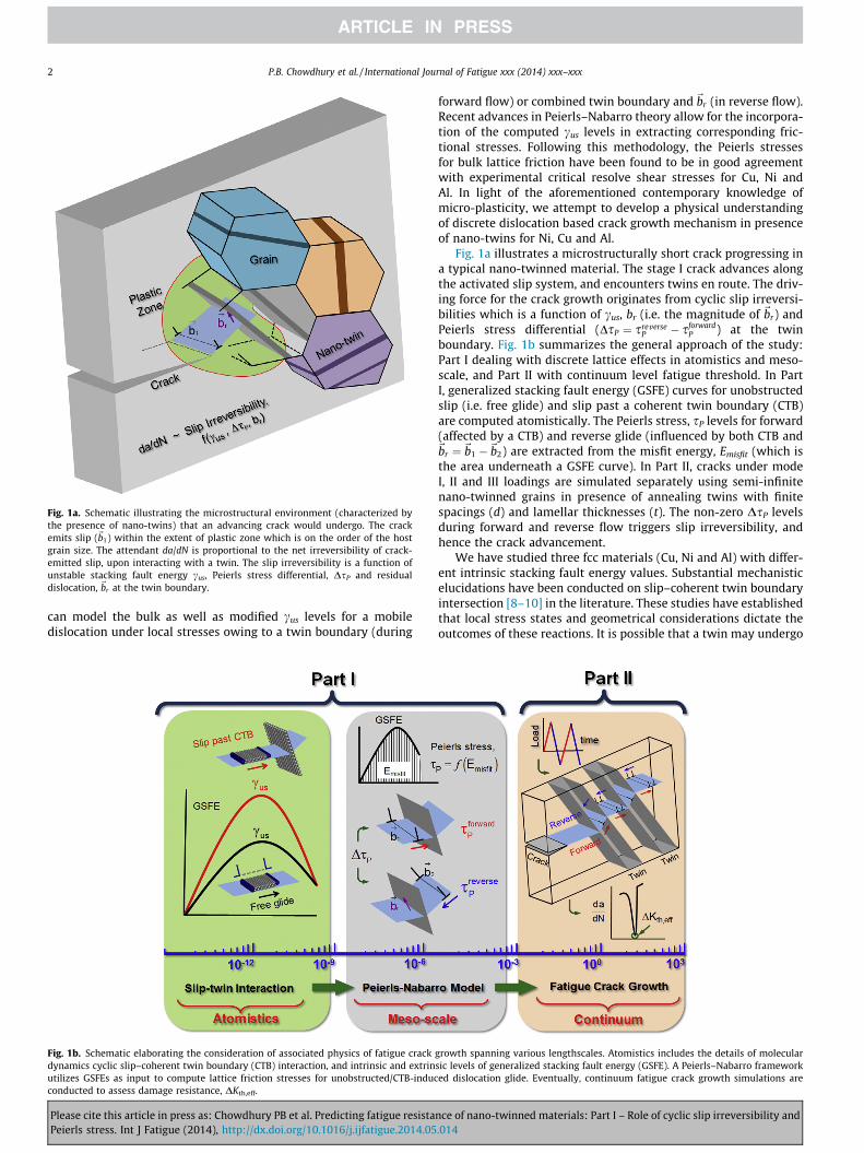
Fig. 1a. Schematic illustrating the microstructural environment (characterized bythe presence of nano-twins) that an advancing crack would undergo. The crackemits slip (~b1) within the extent of plastic zone which is on the order of the hostgrain size. The attendant da/dN is proportional to the net irreversibility of crack-emitted slip, upon interacting with a twin. The slip irreversibility is a function ofunstable stacking fault energy cus, Peierls stress differential, DsP and residualdislocation, ~br at the twin boundary.
2 P.B. Chowdhury et al. / International Journal of Fatigue xxx (2014) xxx–xxx
can model the bulk as well as modified cus levels for a mobiledislocation under local stresses owing to a twin boundary (during
Fig. 1b. Schematic elaborating the consideration of associated physics of fatigue crackdynamics cyclic slip–coherent twin boundary (CTB) interaction, and intrinsic and extrinutilizes GSFEs as input to compute lattice friction stresses for unobstructed/CTB-inducconducted to assess damage resistance, DKth,eff.
Please cite this article in press as: Chowdhury PB et al. Predicting fatigue resistaPeierls stress. Int J Fatigue (2014), http://dx.doi.org/10.1016/j.ijfatigue.2014.05
forward flow) or combined twin boundary and~br (in reverse flow).Recent advances in Peierls–Nabarro theory allow for the incorpora-tion of the computed cus levels in extracting corresponding fric-tional stresses. Following this methodology, the Peierls stressesfor bulk lattice friction have been found to be in good agreementwith experimental critical resolve shear stresses for Cu, Ni andAl. In light of the aforementioned contemporary knowledge ofmicro-plasticity, we attempt to develop a physical understandingof discrete dislocation based crack growth mechanism in presenceof nano-twins for Ni, Cu and Al.
Fig. 1a illustrates a microstructurally short crack progressing ina typical nano-twinned material. The stage I crack advances alongthe activated slip system, and encounters twins en route. The driv-ing force for the crack growth originates from cyclic slip irreversi-bilities which is a function of cus, br (i.e. the magnitude of ~br) andPeierls stress differential (DsP ¼ sreverse
P � sforwardP ) at the twin
boundary. Fig. 1b summarizes the general approach of the study:Part I dealing with discrete lattice effects in atomistics and meso-scale, and Part II with continuum level fatigue threshold. In PartI, generalized stacking fault energy (GSFE) curves for unobstructedslip (i.e. free glide) and slip past a coherent twin boundary (CTB)are computed atomistically. The Peierls stress, sP levels for forward(affected by a CTB) and reverse glide (influenced by both CTB and~br ¼~b1 �~b2) are extracted from the misfit energy, Emisfit (which isthe area underneath a GSFE curve). In Part II, cracks under modeI, II and III loadings are simulated separately using semi-infinitenano-twinned grains in presence of annealing twins with finitespacings (d) and lamellar thicknesses (t). The non-zero DsP levelsduring forward and reverse flow triggers slip irreversibility, andhence the crack advancement.
We have studied three fcc materials (Cu, Ni and Al) with differ-ent intrinsic stacking fault energy values. Substantial mechanisticelucidations have been conducted on slip–coherent twin boundaryintersection [8–10] in the literature. These studies have establishedthat local stress states and geometrical considerations dictate theoutcomes of these reactions. It is possible that a twin may undergo
growth spanning various lengthscales. Atomistics includes the details of molecularsic levels of generalized stacking fault energy (GSFE). A Peierls–Nabarro frameworked dislocation glide. Eventually, continuum fatigue crack growth simulations are
nce of nano-twinned materials: Part I – Role of cyclic slip irreversibility and.014
P.B. Chowdhury et al. / International Journal of Fatigue xxx (2014) xxx–xxx 3
various local stress states, depending on its relative orientation tothe applied loading direction. Thus, two extremities of local stresssituations (i.e. maximum and zero resolved shear stresses on twinboundary plane) have been examined in the present analyses. Wenote that the additional refinement in extracting defect propertiesfrom atomistics can still be a subject of further research. Neverthe-less, we observe reasonable agreement of damage metrics withearlier experimental findings (in the Part II of this study), utilizingthe current atomistic data. The contribution of this report could bedeemed as isolating the micro-mechanism of damage propagation,and providing a mechanistic rationale for the effects of twins thereon.
2. Methods – molecular dynamics
Molecular dynamics is the simulation of time evolution ofatomic nuclei (considered as classical Newtonian particles) by inte-grating their equations of motions [11]. In the current work, we useLAMMPS (Large-scale Atomic/Molecular Massively Parallel Simulator)simulation package, developed at Sandia National Laboratories(lammps.sandia.gov) [12]. Time-dependent effective force fieldbinding the atomic nuclei is modeled through semi-empiricalEmbedded Atom Model (EAM) formulations [13]. For Cu, Ni andAl, the EAM potentials developed by Mishin et al. [14], Foylesand Hoyt [15] and Mishin et al. [16] have been employed respec-tively in the present work.
A simulation supercell of a nano-twinned single crystal grain isconstructed. Prior to applying deformation, the nano-twinned grainis relaxed using conjugate gradient energy minimization algorithm[11] to obtain a stable configuration. 3-D periodic boundary condi-tions are enforced to simulate a system of bulk material. A numberof supercells have been constructed with different twin thicknessesand source to twin distances. For each system, the size of the super-cell is configured to ensure the convergence of physical observables(e.g. temperature, pressure, kinetic and potential energy of thesystem) to the system size independence. An isobaric-isothermal(also known as NPT) ensemble has been utilized during thedeformation i.e. constant N (total number of atoms), P (externalpressure), and T (absolute temperature). Nose–Hoover thermostatalgorithm is utilized to keep the absolute temperature level at10 K. Velocity verlet time-integrator has been used to advance thedynamics of applied deformations. Current computational capacitylimits molecular dynamics simulations to run for several hundred
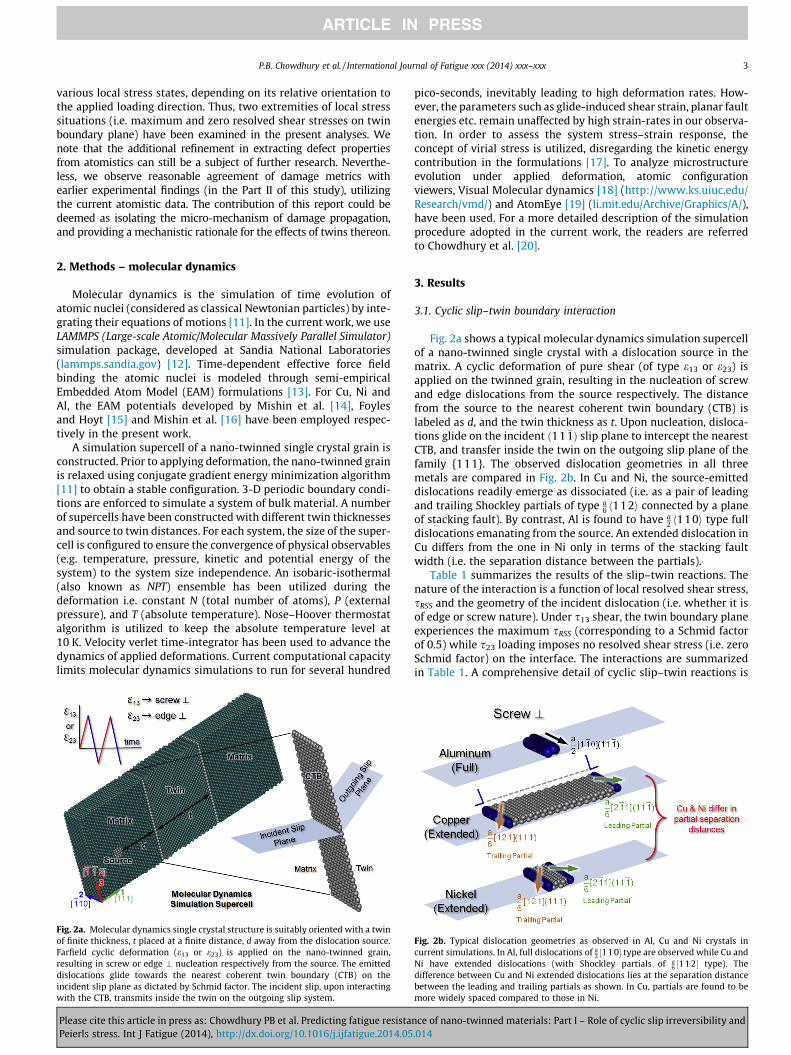
Fig. 2a. Molecular dynamics single crystal structure is suitably oriented with a twinof finite thickness, t placed at a finite distance, d away from the dislocation source.Farfield cyclic deformation (e13 or e23) is applied on the nano-twinned grain,resulting in screw or edge \ nucleation respectively from the source. The emitteddislocations glide towards the nearest coherent twin boundary (CTB) on theincident slip plane as dictated by Schmid factor. The incident slip, upon interactingwith the CTB, transmits inside the twin on the outgoing slip system.
Please cite this article in press as: Chowdhury PB et al. Predicting fatigue resistaPeierls stress. Int J Fatigue (2014), http://dx.doi.org/10.1016/j.ijfatigue.2014.05
pico-seconds, inevitably leading to high deformation rates. How-ever, the parameters such as glide-induced shear strain, planar faultenergies etc. remain unaffected by high strain-rates in our observa-tion. In order to assess the system stress–strain response, theconcept of virial stress is utilized, disregarding the kinetic energycontribution in the formulations [17]. To analyze microstructureevolution under applied deformation, atomic configurationviewers, Visual Molecular dynamics [18] (http://www.ks.uiuc.edu/Research/vmd/) and AtomEye [19] (li.mit.edu/Archive/Graphics/A/),have been used. For a more detailed description of the simulationprocedure adopted in the current work, the readers are referredto Chowdhury et al. [20].
3. Results
3.1. Cyclic slip–twin boundary interaction
Fig. 2a shows a typical molecular dynamics simulation supercellof a nano-twinned single crystal with a dislocation source in thematrix. A cyclic deformation of pure shear (of type e13 or e23) isapplied on the twinned grain, resulting in the nucleation of screwand edge dislocations from the source respectively. The distancefrom the source to the nearest coherent twin boundary (CTB) islabeled as d, and the twin thickness as t. Upon nucleation, disloca-tions glide on the incident ð11 �1Þ slip plane to intercept the nearestCTB, and transfer inside the twin on the outgoing slip plane of thefamily {111}. The observed dislocation geometries in all threemetals are compared in Fig. 2b. In Cu and Ni, the source-emitteddislocations readily emerge as dissociated (i.e. as a pair of leadingand trailing Shockley partials of type a
6 h112i connected by a planeof stacking fault). By contrast, Al is found to have a
2 h110i type fulldislocations emanating from the source. An extended dislocation inCu differs from the one in Ni only in terms of the stacking faultwidth (i.e. the separation distance between the partials).
Table 1 summarizes the results of the slip–twin reactions. Thenature of the interaction is a function of local resolved shear stress,sRSS and the geometry of the incident dislocation (i.e. whether it isof edge or screw nature). Under s13 shear, the twin boundary planeexperiences the maximum sRSS (corresponding to a Schmid factorof 0.5) while s23 loading imposes no resolved shear stress (i.e. zeroSchmid factor) on the interface. The interactions are summarizedin Table 1. A comprehensive detail of cyclic slip–twin reactions is
Fig. 2b. Typical dislocation geometries as observed in Al, Cu and Ni crystals incurrent simulations. In Al, full dislocations of a
2 ½110� type are observed while Cu andNi have extended dislocations (with Shockley partials of a
6 ½112� type). Thedifference between Cu and Ni extended dislocations lies at the separation distancebetween the leading and trailing partials as shown. In Cu, partials are found to bemore widely spaced compared to those in Ni.
nce of nano-twinned materials: Part I – Role of cyclic slip irreversibility and.014
0.39 0.5 0.39 Transmission and Incorporation a2 ½1 �10� 0 a
2 ½1 �10�T 0 a2 ½01 �1�
0.41 0 0.41 Transmission 0 a2 ½101� 0 a
2 ½101�T a3 ½�1 �11�T
Table 2Intrinsic stacking fault energy (cisf) and unstable stacking fault energy in Cu, Ni and Al for h112i(111) slip system from embedded atomic method (EAM) potentials as comparedwith experimental and density functional theory (DFT) values from literature.
Material cisf (mJ/m2) cus (mJ/m2) cisf/cus (current) Dislocation type
Current (EAM) Literature (experiment) Current (EAM) Literature (DFT)
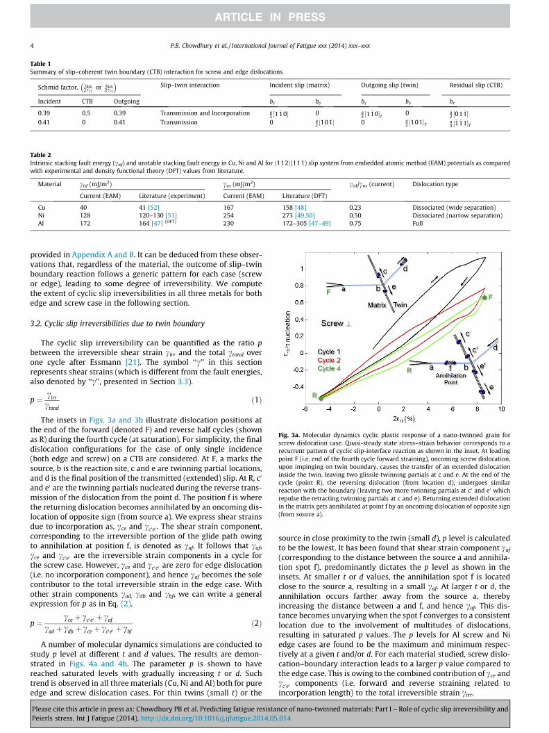
Fig. 3a. Molecular dynamics cyclic plastic response of a nano-twinned grain forscrew dislocation case. Quasi-steady state stress–strain behavior corresponds to arecurrent pattern of cyclic slip-interface reaction as shown in the inset. At loadingpoint F (i.e. end of the fourth cycle forward straining), oncoming screw dislocation,upon impinging on twin boundary, causes the transfer of an extended dislocationinside the twin, leaving two glissile twinning partials at c and e. At the end of thecycle (point R), the reversing dislocation (from location d), undergoes similarreaction with the boundary (leaving two more twinning partials at c0 and e0 whichrepulse the retracting twinning partials at c and e). Returning extended dislocationin the matrix gets annihilated at point f by an oncoming dislocation of opposite sign(from source a).
4 P.B. Chowdhury et al. / International Journal of Fatigue xxx (2014) xxx–xxx
provided in Appendix A and B. It can be deduced from these obser-vations that, regardless of the material, the outcome of slip–twinboundary reaction follows a generic pattern for each case (screwor edge), leading to some degree of irreversibility. We computethe extent of cyclic slip irreversibilities in all three metals for bothedge and screw case in the following section.
3.2. Cyclic slip irreversibilities due to twin boundary
The cyclic slip irreversibility can be quantified as the ratio pbetween the irreversible shear strain cirr and the total ctotal overone cycle after Essmann [21]. The symbol ‘‘c’’ in this sectionrepresents shear strains (which is different from the fault energies,also denoted by ‘‘c’’, presented in Section 3.3).
p ¼ cirr
ctotalð1Þ
The insets in Figs. 3a and 3b illustrate dislocation positions atthe end of the forward (denoted F) and reverse half cycles (shownas R) during the fourth cycle (at saturation). For simplicity, the finaldislocation configurations for the case of only single incidence(both edge and screw) on a CTB are considered. At F, a marks thesource, b is the reaction site, c and e are twinning partial locations,and d is the final position of the transmitted (extended) slip. At R, c0
and e0 are the twinning partials nucleated during the reverse trans-mission of the dislocation from the point d. The position f is wherethe returning dislocation becomes annihilated by an oncoming dis-location of opposite sign (from source a). We express shear strainsdue to incorporation as, cce and cc0e0 . The shear strain component,corresponding to the irreversible portion of the glide path owingto annihilation at position f, is denoted as caf. It follows that caf,cce and cc0e0 are the irreversible strain components in a cycle forthe screw case. However, cce and cc0e0 are zero for edge dislocation(i.e. no incorporation component), and hence caf becomes the solecontributor to the total irreversible strain in the edge case. Withother strain components cad, cdb and cbf, we can write a generalexpression for p as in Eq. (2).
p ¼cce þ cc0e0 þ caf
cad þ cdb þ cce þ cc0e0 þ cbfð2Þ
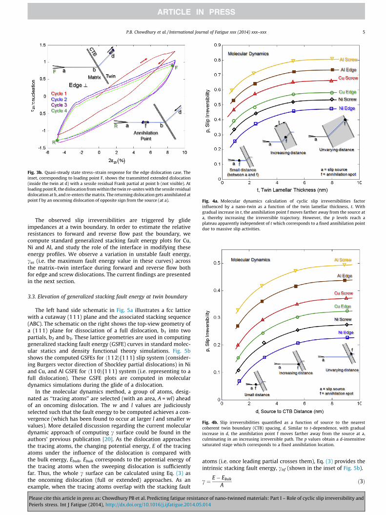
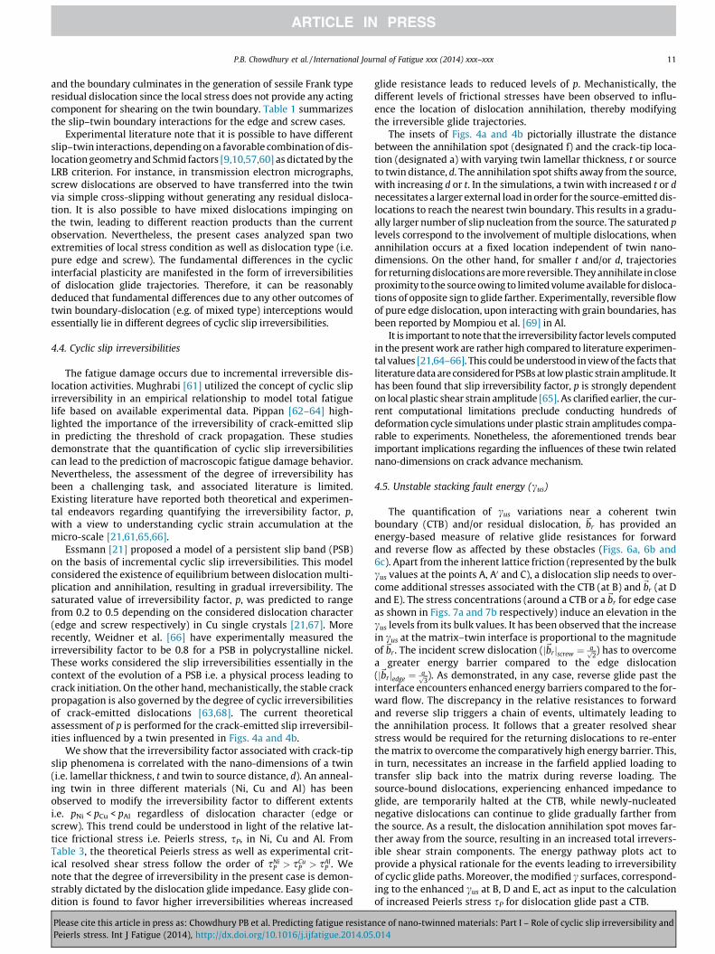
A number of molecular dynamics simulations are conducted tostudy p level at different t and d values. The results are demon-strated in Figs. 4a and 4b. The parameter p is shown to havereached saturated levels with gradually increasing t or d. Suchtrend is observed in all three materials (Cu, Ni and Al) both for pureedge and screw dislocation cases. For thin twins (small t) or the
Please cite this article in press as: Chowdhury PB et al. Predicting fatigue resistaPeierls stress. Int J Fatigue (2014), http://dx.doi.org/10.1016/j.ijfatigue.2014.05
source in close proximity to the twin (small d), p level is calculatedto be the lowest. It has been found that shear strain component caf
(corresponding to the distance between the source a and annihila-tion spot f), predominantly dictates the p level as shown in theinsets. At smaller t or d values, the annihilation spot f is locatedclose to the source a, resulting in a small caf. At larger t or d, theannihilation occurs farther away from the source a, therebyincreasing the distance between a and f, and hence caf. This dis-tance becomes unvarying when the spot f converges to a consistentlocation due to the involvement of multitudes of dislocations,resulting in saturated p values. The p levels for Al screw and Niedge cases are found to be the maximum and minimum respec-tively at a given t and/or d. For each material studied, screw dislo-cation–boundary interaction leads to a larger p value compared tothe edge case. This is owing to the combined contribution of cce andcc0e0 components (i.e. forward and reverse straining related toincorporation length) to the total irreversible strain cirr.
nce of nano-twinned materials: Part I – Role of cyclic slip irreversibility and.014
Fig. 3b. Quasi-steady state stress–strain response for the edge dislocation case. Theinset, corresponding to loading point F, shows the transmitted extended dislocation(inside the twin at d) with a sessile residual Frank partial at point b (not visible). Atloading point R, the dislocation from within the twin re-unites with the sessile residualdislocation at b, and re-enters the matrix. The returning dislocation gets annihilated atpoint f by an oncoming dislocation of opposite sign from the source (at a). ig. 4a. Molecular dynamics calculation of cyclic slip irreversibilities factor
fluenced by a nano-twin as a function of the twin lamellar thickness, t. Withradual increase in t, the annihilation point f moves farther away from the source at, thereby increasing the irreversible trajectory. However, the p levels reach alateau apparently independent of t which corresponds to a fixed annihilation pointue to massive slip activities.
Fig. 4b. Slip irreversibilities quantified as a function of source to the nearestcoherent twin boundary (CTB) spacing, d. Similar to t-dependence, with gradualincrease in d, the annihilation point f moves farther away from the source at a,culminating in an increasing irreversible path. The p values obtain a d-insensitivesaturated stage which corresponds to a fixed annihilation location.
P.B. Chowdhury et al. / International Journal of Fatigue xxx (2014) xxx–xxx 5
The observed slip irreversibilities are triggered by glideimpedances at a twin boundary. In order to estimate the relativeresistances to forward and reverse flow past the boundary, wecompute standard generalized stacking fault energy plots for Cu,Ni and Al, and study the role of the interface in modifying theseenergy profiles. We observe a variation in unstable fault energy,cus (i.e. the maximum fault energy value in these curves) acrossthe matrix–twin interface during forward and reverse flow bothfor edge and screw dislocations. The current findings are presentedin the next section.
3.3. Elevation of generalized stacking fault energy at twin boundary
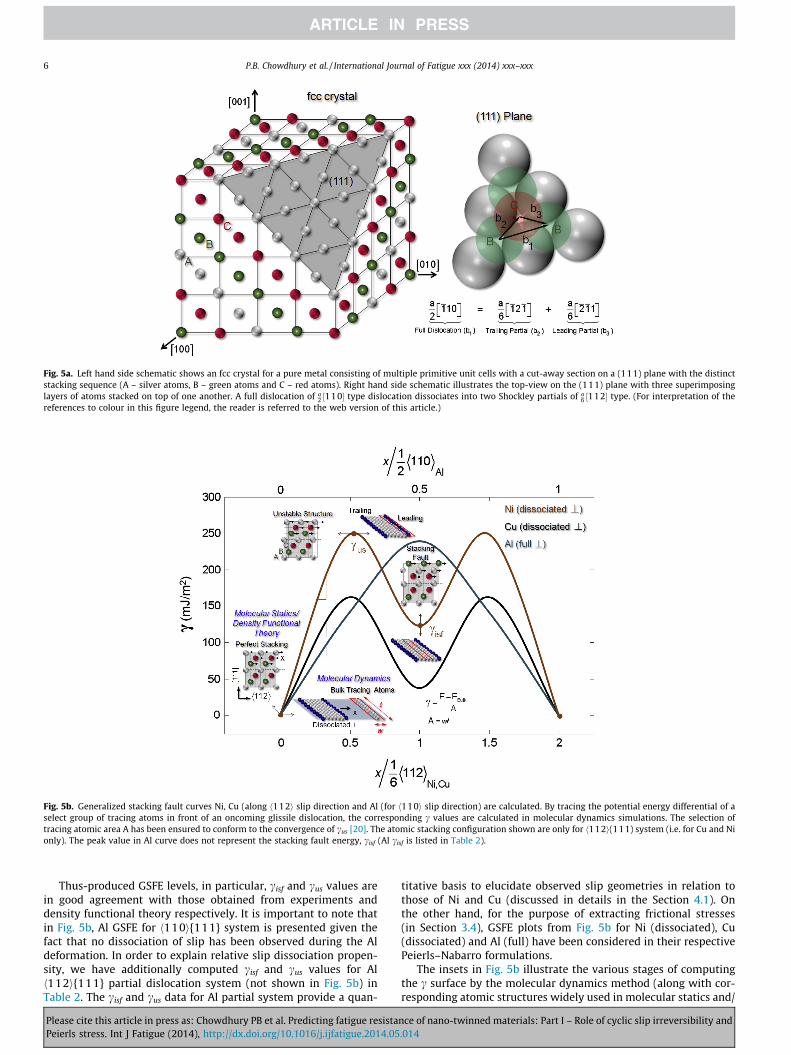
The left hand side schematic in Fig. 5a illustrates a fcc latticewith a cutaway (111) plane and the associated stacking sequence(ABC). The schematic on the right shows the top-view geometry ofa (111) plane for dissociation of a full dislocation, b1 into twopartials, b2 and b3. These lattice geometries are used in computinggeneralized stacking fault energy (GSFE) curves in standard molec-ular statics and density functional theory simulations. Fig. 5bshows the computed GSFEs for h112i{111} slip system (consider-ing Burgers vector direction of Shockley partial dislocations) in Niand Cu, and Al GSFE for h110i{111} system (i.e. representing to afull dislocation). These GSFE plots are computed in moleculardynamics simulations during the glide of a dislocation.
In the molecular dynamics method, a group of atoms, desig-nated as ‘‘tracing atoms’’ are selected (with an area, A = wl) aheadof an oncoming dislocation. The w and l values are judiciouslyselected such that the fault energy to be computed achieves a con-vergence (which has been found to occur at larger l and smaller wvalues). More detailed discussion regarding the current moleculardynamic approach of computing c surface could be found in theauthors’ previous publication [20]. As the dislocation approachesthe tracing atoms, the changing potential energy, E of the tracingatoms under the influence of the dislocation is compared withthe bulk energy, Ebulk. Ebulk corresponds to the potential energy ofthe tracing atoms when the sweeping dislocation is sufficientlyfar. Thus, the whole c surface can be calculated using Eq. (3) asthe oncoming dislocation (full or extended) approaches. As anexample, when the tracing atoms overlap with the stacking fault
Please cite this article in press as: Chowdhury PB et al. Predicting fatigue resistaPeierls stress. Int J Fatigue (2014), http://dx.doi.org/10.1016/j.ijfatigue.2014.05
Fingapd
atoms (i.e. once leading partial crosses them), Eq. (3) provides theintrinsic stacking fault energy, cisf (shown in the inset of Fig. 5b).
c ¼ E� EBulk
Að3Þ
nce of nano-twinned materials: Part I – Role of cyclic slip irreversibility and.014
Fig. 5a. Left hand side schematic shows an fcc crystal for a pure metal consisting of multiple primitive unit cells with a cut-away section on a (111) plane with the distinctstacking sequence (A – silver atoms, B – green atoms and C – red atoms). Right hand side schematic illustrates the top-view on the (111) plane with three superimposinglayers of atoms stacked on top of one another. A full dislocation of a
2 ½11 0� type dislocation dissociates into two Shockley partials of a6 ½112� type. (For interpretation of the
references to colour in this figure legend, the reader is referred to the web version of this article.)
Fig. 5b. Generalized stacking fault curves Ni, Cu (along h112i slip direction and Al (for h110i slip direction) are calculated. By tracing the potential energy differential of aselect group of tracing atoms in front of an oncoming glissile dislocation, the corresponding c values are calculated in molecular dynamics simulations. The selection oftracing atomic area A has been ensured to conform to the convergence of cus [20]. The atomic stacking configuration shown are only for h112i(111) system (i.e. for Cu and Nionly). The peak value in Al curve does not represent the stacking fault energy, cisf (Al cisf is listed in Table 2).
6 P.B. Chowdhury et al. / International Journal of Fatigue xxx (2014) xxx–xxx
Thus-produced GSFE levels, in particular, cisf and cus values arein good agreement with those obtained from experiments anddensity functional theory respectively. It is important to note thatin Fig. 5b, Al GSFE for h110i{111} system is presented given thefact that no dissociation of slip has been observed during the Aldeformation. In order to explain relative slip dissociation propen-sity, we have additionally computed cisf and cus values for Alh112i{111} partial dislocation system (not shown in Fig. 5b) inTable 2. The cisf and cus data for Al partial system provide a quan-
Please cite this article in press as: Chowdhury PB et al. Predicting fatigue resistaPeierls stress. Int J Fatigue (2014), http://dx.doi.org/10.1016/j.ijfatigue.2014.05
titative basis to elucidate observed slip geometries in relation tothose of Ni and Cu (discussed in details in the Section 4.1). Onthe other hand, for the purpose of extracting frictional stresses(in Section 3.4), GSFE plots from Fig. 5b for Ni (dissociated), Cu(dissociated) and Al (full) have been considered in their respectivePeierls–Nabarro formulations.
The insets in Fig. 5b illustrate the various stages of computingthe c surface by the molecular dynamics method (along with cor-responding atomic structures widely used in molecular statics and/
nce of nano-twinned materials: Part I – Role of cyclic slip irreversibility and.014
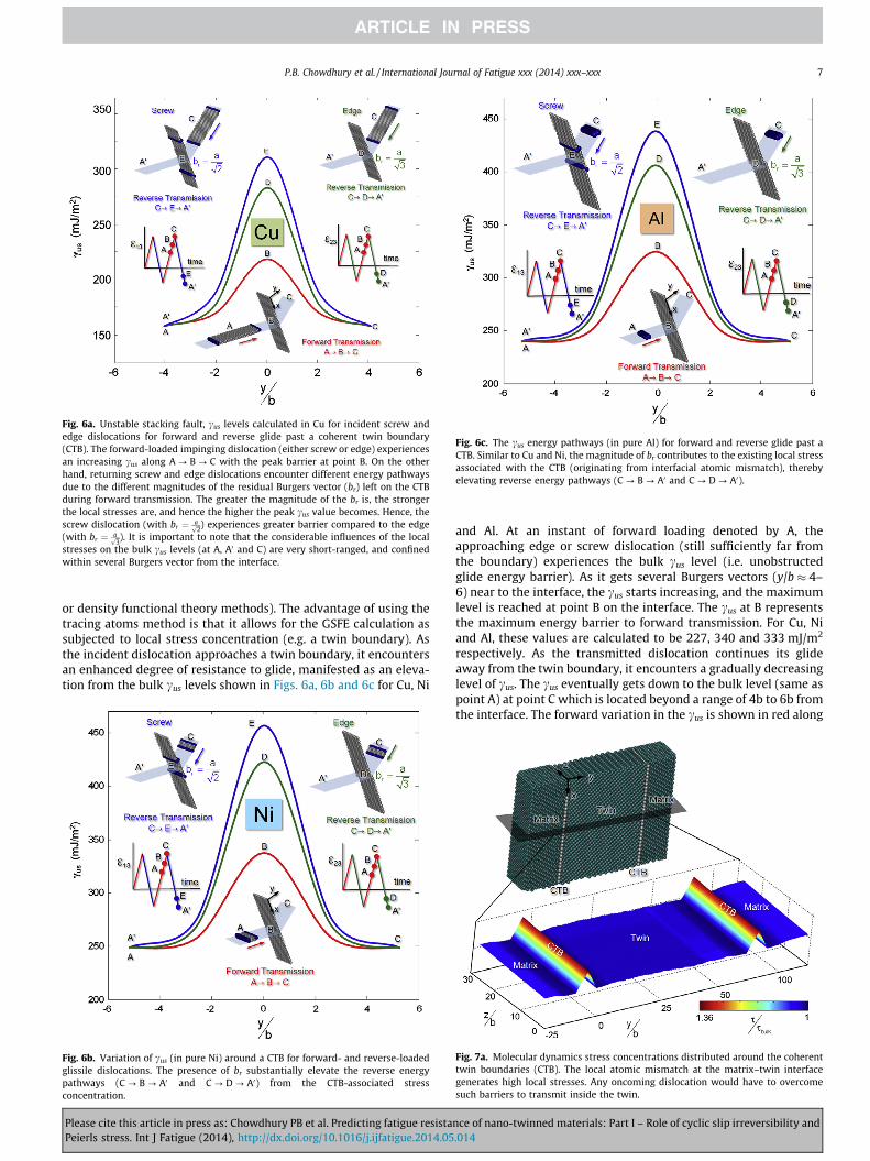
Fig. 6a. Unstable stacking fault, cus levels calculated in Cu for incident screw andedge dislocations for forward and reverse glide past a coherent twin boundary(CTB). The forward-loaded impinging dislocation (either screw or edge) experiencesan increasing cus along A ? B ? C with the peak barrier at point B. On the otherhand, returning screw and edge dislocations encounter different energy pathwaysdue to the different magnitudes of the residual Burgers vector (br) left on the CTBduring forward transmission. The greater the magnitude of the br is, the strongerthe local stresses are, and hence the higher the peak cus value becomes. Hence, thescrew dislocation (with br ¼ affiffi
2p ) experiences greater barrier compared to the edge
(with br ¼ affiffi3p ). It is important to note that the considerable influences of the local
stresses on the bulk cus levels (at A, A0 and C) are very short-ranged, and confinedwithin several Burgers vector from the interface.
ig. 6c. The cus energy pathways (in pure Al) for forward and reverse glide past aTB. Similar to Cu and Ni, the magnitude of br contributes to the existing local stressssociated with the CTB (originating from interfacial atomic mismatch), therebylevating reverse energy pathways (C ? B ? A0 and C ? D ? A0).
P.B. Chowdhury et al. / International Journal of Fatigue xxx (2014) xxx–xxx 7
or density functional theory methods). The advantage of using thetracing atoms method is that it allows for the GSFE calculation assubjected to local stress concentration (e.g. a twin boundary). Asthe incident dislocation approaches a twin boundary, it encountersan enhanced degree of resistance to glide, manifested as an eleva-tion from the bulk cus levels shown in Figs. 6a, 6b and 6c for Cu, Ni
Fig. 6b. Variation of cus (in pure Ni) around a CTB for forward- and reverse-loadedglissile dislocations. The presence of br substantially elevate the reverse energypathways (C ? B ? A0 and C ? D ? A0) from the CTB-associated stressconcentration.
Please cite this article in press as: Chowdhury PB et al. Predicting fatigue resistaPeierls stress. Int J Fatigue (2014), http://dx.doi.org/10.1016/j.ijfatigue.2014.05
FCae
and Al. At an instant of forward loading denoted by A, theapproaching edge or screw dislocation (still sufficiently far fromthe boundary) experiences the bulk cus level (i.e. unobstructedglide energy barrier). As it gets several Burgers vectors (y/b � 4–6) near to the interface, the cus starts increasing, and the maximumlevel is reached at point B on the interface. The cus at B representsthe maximum energy barrier to forward transmission. For Cu, Niand Al, these values are calculated to be 227, 340 and 333 mJ/m2
respectively. As the transmitted dislocation continues its glideaway from the twin boundary, it encounters a gradually decreasinglevel of cus. The cus eventually gets down to the bulk level (same aspoint A) at point C which is located beyond a range of 4b to 6b fromthe interface. The forward variation in the cus is shown in red along
Fig. 7a. Molecular dynamics stress concentrations distributed around the coherenttwin boundaries (CTB). The local atomic mismatch at the matrix–twin interfacegenerates high local stresses. Any oncoming dislocation would have to overcomesuch barriers to transmit inside the twin.
nce of nano-twinned materials: Part I – Role of cyclic slip irreversibility and.014
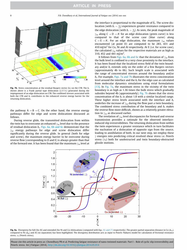
Fig. 7b. Stress concentration at the residual Burgers vector (br) on the CTB. The br
shown above is a Frank partial type dislocation (a3 ½�1 �11�) generated during the
impingement of an edge dislocation on CTB. The combined stresses associated withboth the CTB and br contributes to the enhanced reverse energy barrier for thereturning dislocation.
8 P.B. Chowdhury et al. / International Journal of Fatigue xxx (2014) xxx–xxx
the pathway A ? B ? C. On the other hand, the reverse energypathways differ for edge and screw dislocations discussed asfollows.
During reverse glide, the transmitted dislocation from withinthe twin has to overcome an enhanced cus level due to the presenceof residual dislocation br. Figs. 6a, 6b and 6c demonstrate that thecus energy pathways for edge and screw dislocation differsignificantly during the reverse glide. In general (both for edgeand screw), the maximum energy barrier to be overcome duringreverse flow (corresponding to D and E) is always greater than thatof the forward one. It has been found that the maximum cus level at
Fig. 8a. Disregistry for full (for Al) and extended (for Ni and Cu) dislocations (computed wcompared to Ni (dNi) and Al (no separation) has been highlighted. The disregistry distribstress, sP (Peierls stress).
Please cite this article in press as: Chowdhury PB et al. Predicting fatigue resistaPeierls stress. Int J Fatigue (2014), http://dx.doi.org/10.1016/j.ijfatigue.2014.05
the interface is proportional to the magnitude of~br . The screw dis-location (with br ¼ affiffi
2p ) experiences greater resistance compared to
the edge dislocation (with br ¼ affiffi3p ). As seen, the peak magnitude of
cus along C ? D ? A0 for an edge dislocation (green curve) is lesscompared to that of the screw case (blue curve) alongC ? E ? A0. For an edge dislocation, the maximum cus valuesencountered (at point D) are computed to be 283, 431 and410 mJ/m2 for Cu, Ni and Al respectively. At E (i.e. for screw case),the calculated cus values for the respective materials are as high as310, 452 and 441 mJ/m2.
It follows from Figs. 6a, 6b and 6c that the deviation of cus fromthe bulk level is confined to a very close proximity to the interface.It has been found that the localized stress field of the twin bound-ary and/or br extends only on the order of a few Burgers vectors(approximately 4b to 6b). Such length scale is associated withthe range of concentrated stresses around the boundary and/orbr. For example, Figs. 7a and 7b illustrates the stress concentrationlevel around the interface and the br for the edge case as calculatedfrom molecular dynamics simulations using virial formulations[13]. In Fig. 7a, the maximum stress in the vicinity of the twinboundary is as high as 1.36 times the bulk stress which graduallysubsides beyond 4b (approximately). Fig. 7b shows that the stressconcentration of the br is about 1.8 with a similar localized range.These higher stress levels associated with the interface and br
underlies the increase of cus during the flow past a twin boundary.The combined stress contribution of the boundary and br makesthe reverse flow more difficult, shown as a relatively greater eleva-tion to cus as discussed earlier.
The revelation of cus level discrepancies for forward and reversetransmission provides a rationale for the observed interface-induced slip irreversibilities. The returning dislocation from withinthe twin experiences a greater resistance which in turn facilitatesthe nucleation of a dislocation of opposite sign from the source,leading to annihilation of both. In our next step, we employ thesec energies into predicting critical resolved shear stress i.e. Peierlsstress (sP) both for unobstructed and twin boundary-obstructedglissile motions.
ith Eqs. (6) and (7) respectively). The greater partial separation distance in Cu (dCu),ution acts as input to Peierls–Nabarro model for calculation of frictional resistance
nce of nano-twinned materials: Part I – Role of cyclic slip irreversibility and.014
P.B. Chowdhury et al. / International Journal of Fatigue xxx (2014) xxx–xxx 9
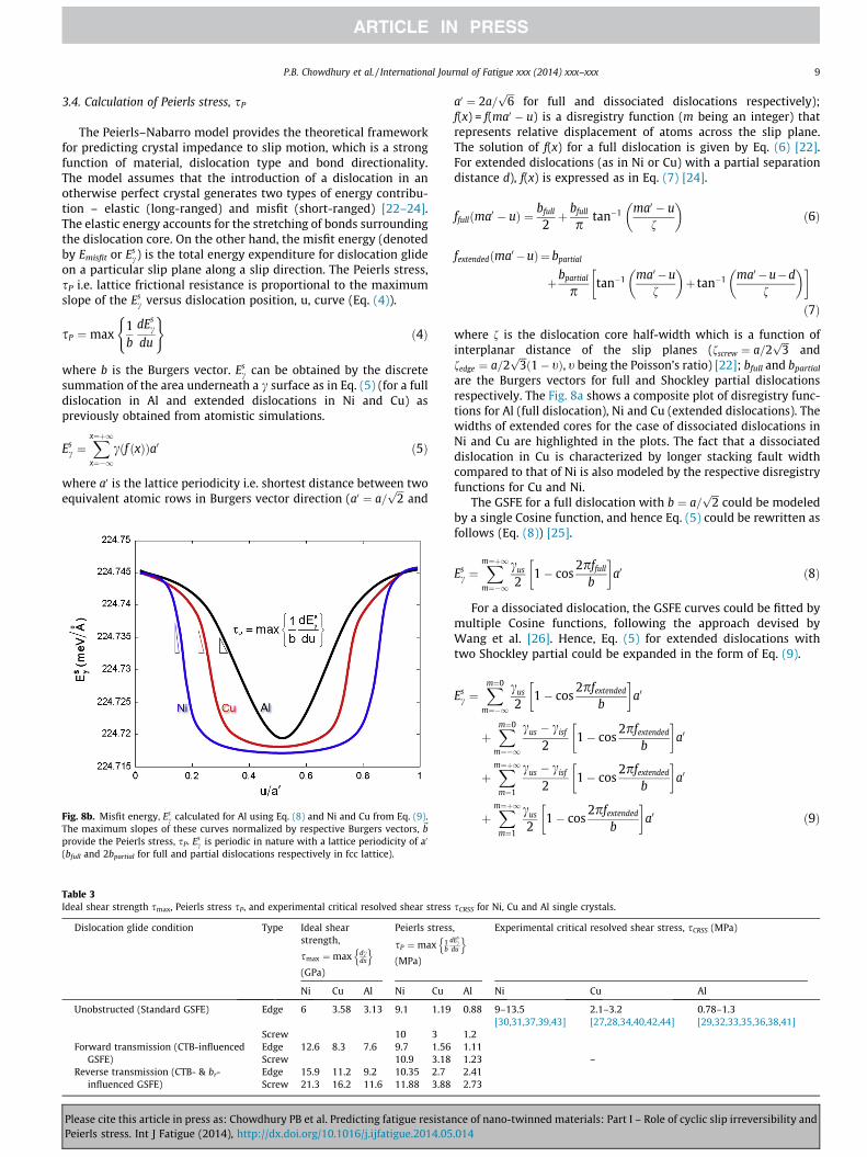
3.4. Calculation of Peierls stress, sP
The Peierls–Nabarro model provides the theoretical frameworkfor predicting crystal impedance to slip motion, which is a strongfunction of material, dislocation type and bond directionality.The model assumes that the introduction of a dislocation in anotherwise perfect crystal generates two types of energy contribu-tion – elastic (long-ranged) and misfit (short-ranged) [22–24].The elastic energy accounts for the stretching of bonds surroundingthe dislocation core. On the other hand, the misfit energy (denotedby Emisfit or Es
c) is the total energy expenditure for dislocation glideon a particular slip plane along a slip direction. The Peierls stress,sP i.e. lattice frictional resistance is proportional to the maximumslope of the Es
c versus dislocation position, u, curve (Eq. (4)).
sP ¼max1b
dEsc
du
( )ð4Þ
where b is the Burgers vector. Esc can be obtained by the discrete
summation of the area underneath a c surface as in Eq. (5) (for a fulldislocation in Al and extended dislocations in Ni and Cu) aspreviously obtained from atomistic simulations.
Esc ¼
Xx¼þ1x¼�1
cðf ðxÞÞa0 ð5Þ
where a0 is the lattice periodicity i.e. shortest distance between twoequivalent atomic rows in Burgers vector direction (a0 ¼ a=
ffiffiffi2p
and
Fig. 8b. Misfit energy, Esc calculated for Al using Eq. (8) and Ni and Cu from Eq. (9).
The maximum slopes of these curves normalized by respective Burgers vectors, ~bprovide the Peierls stress, sP. Es
c is periodic in nature with a lattice periodicity of a0
(bfull and 2bpartial for full and partial dislocations respectively in fcc lattice).
Please cite this article in press as: Chowdhury PB et al. Predicting fatigue resistaPeierls stress. Int J Fatigue (2014), http://dx.doi.org/10.1016/j.ijfatigue.2014.05
a0 ¼ 2a=ffiffiffi6p
for full and dissociated dislocations respectively);f(x) = f(ma0 � u) is a disregistry function (m being an integer) thatrepresents relative displacement of atoms across the slip plane.The solution of f(x) for a full dislocation is given by Eq. (6) [22].For extended dislocations (as in Ni or Cu) with a partial separationdistance d), f(x) is expressed as in Eq. (7) [24].
ffullðma0 � uÞ ¼ bfull
2þ bfull
ptan�1 ma0 � u
f
� �ð6Þ
fextendedðma0 �uÞ¼ bpartial
þbpartial
ptan�1 ma0 �u
f
� �þ tan�1 ma0 �u�d
f
� �� �ð7Þ
where f is the dislocation core half-width which is a function ofinterplanar distance of the slip planes (fscrew ¼ a=2
ffiffiffi3p
andfedge ¼ a=2
ffiffiffi3pð1� tÞ, t being the Poisson’s ratio) [22]; bfull and bpartial
are the Burgers vectors for full and Shockley partial dislocationsrespectively. The Fig. 8a shows a composite plot of disregistry func-tions for Al (full dislocation), Ni and Cu (extended dislocations). Thewidths of extended cores for the case of dissociated dislocations inNi and Cu are highlighted in the plots. The fact that a dissociateddislocation in Cu is characterized by longer stacking fault widthcompared to that of Ni is also modeled by the respective disregistryfunctions for Cu and Ni.
The GSFE for a full dislocation with b ¼ a=ffiffiffi2p
could be modeledby a single Cosine function, and hence Eq. (5) could be rewritten asfollows (Eq. (8)) [25].
Esc ¼
Xm¼þ1m¼�1
cus
21� cos
2pffull
b
� �a0 ð8Þ
For a dissociated dislocation, the GSFE curves could be fitted bymultiple Cosine functions, following the approach devised byWang et al. [26]. Hence, Eq. (5) for extended dislocations withtwo Shockley partial could be expanded in the form of Eq. (9).
Esc ¼
Xm¼0
m¼�1
cus
21� cos
2pfextended
b
� �a0
þXm¼0
m¼�1
cus � cisf
21� cos
2pfextended
b
� �a0
þXm¼þ1m¼1
cus � cisf
21� cos
2pfextended
b
� �a0
þXm¼þ1m¼1
cus
21� cos
2pfextended
b
� �a0 ð9Þ
sCRSS for Ni, Cu and Al single crystals.
,Esc
du
o Experimental critical resolved shear stress, sCRSS (MPa)
Al Ni Cu Al
0.88 9–13.5[30,31,37,39,43]
2.1–3.2[27,28,34,40,42,44]
0.78–1.3[29,32,33,35,36,38,41]
1.21.111.23 –2.412.73
nce of nano-twinned materials: Part I – Role of cyclic slip irreversibility and.014
10 P.B. Chowdhury et al. / International Journal of Fatigue xxx (2014) xxx–xxx
In Fig. 8b, the misfit energy Esc for free dislocation glide for Ni,
Cu and Al are plotted together. In the present study, the Peierlsstresses for both unobstructed and obstructed (twin boundary-induced) glide have been computed utilizing the above-mentionedapproach. In order to extract the twin boundary-restricted Peierlsstresses (for forward and reverse flow), total misfit energies arecalculated from the modified levels of GSFE (i.e. with increasedcus) using Eqs. (8) and (9). Eq. (4) then provides the extrinsic levelsof frictional stresses, sP. Table 3 lists the computed Peierls stressesalong with the ideal shear strengths, smax (which is the maximumslope of a GSFE curve) and experimental critical resolved shearstresses, sCRSS for Ni, Cu and Al. It follows that the thus-computedPeierls stresses for free glide possess a good agreement with theexperimentally measured critical resolved shear stress in all threematerials (Cu, Ni and Al) [27–44]. The current method of usingmodified/unmodified GSFEs in Peierls–Nabarro formulationsprovides forward and reverse glide resistance as imposed by thematrix–twin interface. These lattice frictional stresses constituteimportant ingredients in implementing dislocation glide basedfatigue crack growth in Part II of this study.
4. Discussion
4.1. Slip characteristics
In the present simulations, Al dislocations emerge as fullwhile Cu and Ni dislocations are of extended type (i.e. leadingand trailing Shockley partials connected by a staking fault rib-bon). The splitting distance for a Cu extended dislocation is lar-ger than that of Ni as shown in Fig. 2b. Classically, the stackingfault width for an extended dislocation is inversely proportionalto intrinsic staking fault energy, cisf [22] based on the elasticforce balance between two partials. However, recent literature[45] indicates that the cisf by itself is an insufficient parameterto dictate whether the prevalent slip type would be full or dis-sociated. It has been proposed that the dissociation criterionfor Al, Cu and Ni could be understood by their respective gener-alized staking fault energies (GSFE) [45,46]. In order to rational-ize the dissociation characteristics in Ni, Cu and Al, we representthe respective c surfaces by the ratio between the intrinsicstacking fault energy and unstable fault energy, cus. The com-puted cisf and cus values for Ni, Cu and Al are provided in Table 2.The cus and cisf values for these materials are found to be in goodagreement with density functional theory [47–50] and experimen-tal results [51,52] respectively.
Rice [53] first proposed that the peak energy in a GSFE plot(i.e. unstable stacking fault energy, cus) is the barrier for slipnucleation. Considering the case of an extended dislocation, theleading Shockley partial has to overcome cus as in Fig. 5b. Theglide of this leading partial creates a plane of stacking fault inthe wake with an fault energy of cisf. The width of this stackingfault plane depends on energy balance between the mutual elasticrepulsion and the total fault energy. Essentially, the relevantenergy barrier for the trailing partial to overcome is now (cus -� cisf). In other words, large difference between cisf and cus facili-tates widening of partial splitting. Therefore, a lower cisf/cus ratioin any material would indicate a greater propensity towards dis-sociation into partials with increased separation between partials.The cisf/cus ratios for Al, Ni and Cu are calculated to be 0.75, 0.50and 0.23 respectively which are in good agreement with literaturevalue [45]. Consequently, Cu dislocations are found to have widerseparation compared to Ni while Al dislocations remain as full.Earlier experimental literature [54,55] have confirmed the obser-vation of type a
2 h110i full dislocations in cyclically deformed Al.The simulation-related findings are summarized in Table 2.
Please cite this article in press as: Chowdhury PB et al. Predicting fatigue resistaPeierls stress. Int J Fatigue (2014), http://dx.doi.org/10.1016/j.ijfatigue.2014.05
4.2. Cyclic saturation
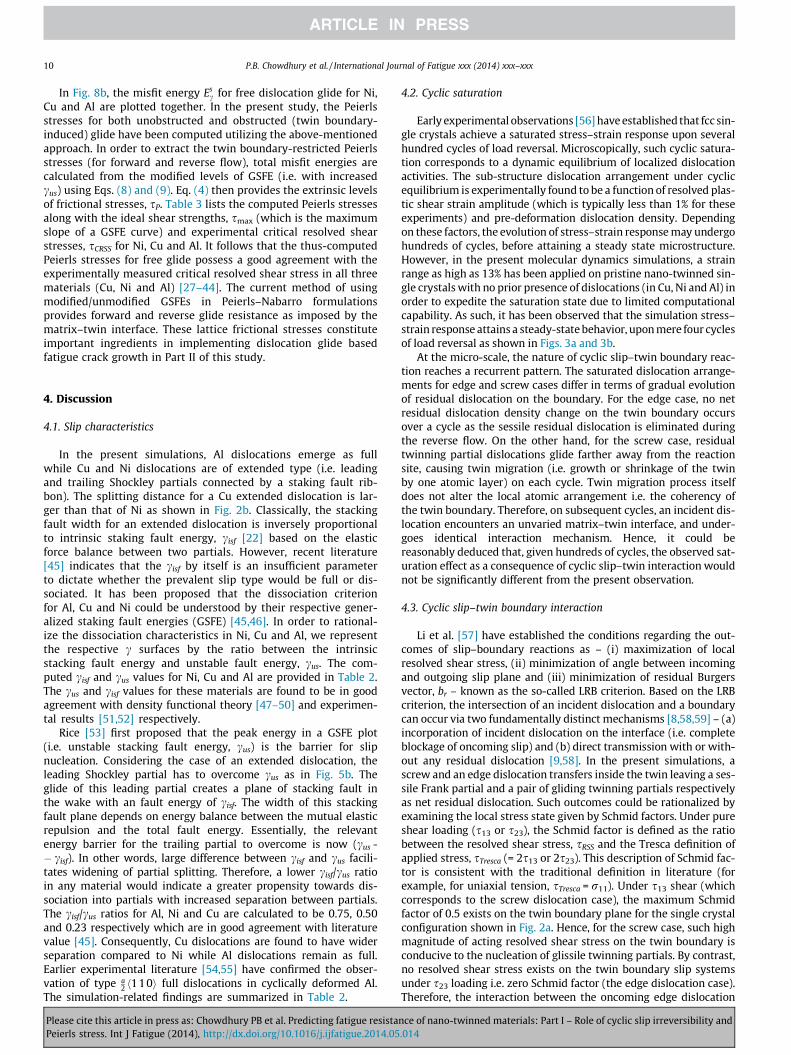
Early experimental observations [56] have established that fcc sin-gle crystals achieve a saturated stress–strain response upon severalhundred cycles of load reversal. Microscopically, such cyclic satura-tion corresponds to a dynamic equilibrium of localized dislocationactivities. The sub-structure dislocation arrangement under cyclicequilibrium is experimentally found to be a function of resolved plas-tic shear strain amplitude (which is typically less than 1% for theseexperiments) and pre-deformation dislocation density. Dependingon these factors, the evolution of stress–strain response may undergohundreds of cycles, before attaining a steady state microstructure.However, in the present molecular dynamics simulations, a strainrange as high as 13% has been applied on pristine nano-twinned sin-gle crystals with no prior presence of dislocations (in Cu, Ni and Al) inorder to expedite the saturation state due to limited computationalcapability. As such, it has been observed that the simulation stress–strain response attains a steady-state behavior, upon mere four cyclesof load reversal as shown in Figs. 3a and 3b.
At the micro-scale, the nature of cyclic slip–twin boundary reac-tion reaches a recurrent pattern. The saturated dislocation arrange-ments for edge and screw cases differ in terms of gradual evolutionof residual dislocation on the boundary. For the edge case, no netresidual dislocation density change on the twin boundary occursover a cycle as the sessile residual dislocation is eliminated duringthe reverse flow. On the other hand, for the screw case, residualtwinning partial dislocations glide farther away from the reactionsite, causing twin migration (i.e. growth or shrinkage of the twinby one atomic layer) on each cycle. Twin migration process itselfdoes not alter the local atomic arrangement i.e. the coherency ofthe twin boundary. Therefore, on subsequent cycles, an incident dis-location encounters an unvaried matrix–twin interface, and under-goes identical interaction mechanism. Hence, it could bereasonably deduced that, given hundreds of cycles, the observed sat-uration effect as a consequence of cyclic slip–twin interaction wouldnot be significantly different from the present observation.
4.3. Cyclic slip–twin boundary interaction
Li et al. [57] have established the conditions regarding the out-comes of slip–boundary reactions as – (i) maximization of localresolved shear stress, (ii) minimization of angle between incomingand outgoing slip plane and (iii) minimization of residual Burgersvector, br – known as the so-called LRB criterion. Based on the LRBcriterion, the intersection of an incident dislocation and a boundarycan occur via two fundamentally distinct mechanisms [8,58,59] – (a)incorporation of incident dislocation on the interface (i.e. completeblockage of oncoming slip) and (b) direct transmission with or with-out any residual dislocation [9,58]. In the present simulations, ascrew and an edge dislocation transfers inside the twin leaving a ses-sile Frank partial and a pair of gliding twinning partials respectivelyas net residual dislocation. Such outcomes could be rationalized byexamining the local stress state given by Schmid factors. Under pureshear loading (s13 or s23), the Schmid factor is defined as the ratiobetween the resolved shear stress, sRSS and the Tresca definition ofapplied stress, sTresca (= 2s13 or 2s23). This description of Schmid fac-tor is consistent with the traditional definition in literature (forexample, for uniaxial tension, sTresca = r11). Under s13 shear (whichcorresponds to the screw dislocation case), the maximum Schmidfactor of 0.5 exists on the twin boundary plane for the single crystalconfiguration shown in Fig. 2a. Hence, for the screw case, such highmagnitude of acting resolved shear stress on the twin boundary isconducive to the nucleation of glissile twinning partials. By contrast,no resolved shear stress exists on the twin boundary slip systemsunder s23 loading i.e. zero Schmid factor (the edge dislocation case).Therefore, the interaction between the oncoming edge dislocation
nce of nano-twinned materials: Part I – Role of cyclic slip irreversibility and.014
P.B. Chowdhury et al. / International Journal of Fatigue xxx (2014) xxx–xxx 11
and the boundary culminates in the generation of sessile Frank typeresidual dislocation since the local stress does not provide any actingcomponent for shearing on the twin boundary. Table 1 summarizesthe slip–twin boundary interactions for the edge and screw cases.
Experimental literature note that it is possible to have differentslip–twin interactions, depending on a favorable combination of dis-location geometry and Schmid factors [9,10,57,60] as dictated by theLRB criterion. For instance, in transmission electron micrographs,screw dislocations are observed to have transferred into the twinvia simple cross-slipping without generating any residual disloca-tion. It is also possible to have mixed dislocations impinging onthe twin, leading to different reaction products than the currentobservation. Nevertheless, the present cases analyzed span twoextremities of local stress condition as well as dislocation type (i.e.pure edge and screw). The fundamental differences in the cyclicinterfacial plasticity are manifested in the form of irreversibilitiesof dislocation glide trajectories. Therefore, it can be reasonablydeduced that fundamental differences due to any other outcomes oftwin boundary-dislocation (e.g. of mixed type) interceptions wouldessentially lie in different degrees of cyclic slip irreversibilities.
4.4. Cyclic slip irreversibilities
The fatigue damage occurs due to incremental irreversible dis-location activities. Mughrabi [61] utilized the concept of cyclic slipirreversibility in an empirical relationship to model total fatiguelife based on available experimental data. Pippan [62–64] high-lighted the importance of the irreversibility of crack-emitted slipin predicting the threshold of crack propagation. These studiesdemonstrate that the quantification of cyclic slip irreversibilitiescan lead to the prediction of macroscopic fatigue damage behavior.Nevertheless, the assessment of the degree of irreversibility hasbeen a challenging task, and associated literature is limited.Existing literature have reported both theoretical and experimen-tal endeavors regarding quantifying the irreversibility factor, p,with a view to understanding cyclic strain accumulation at themicro-scale [21,61,65,66].
Essmann [21] proposed a model of a persistent slip band (PSB)on the basis of incremental cyclic slip irreversibilities. This modelconsidered the existence of equilibrium between dislocation multi-plication and annihilation, resulting in gradual irreversibility. Thesaturated value of irreversibility factor, p, was predicted to rangefrom 0.2 to 0.5 depending on the considered dislocation character(edge and screw respectively) in Cu single crystals [21,67]. Morerecently, Weidner et al. [66] have experimentally measured theirreversibility factor to be 0.8 for a PSB in polycrystalline nickel.These works considered the slip irreversibilities essentially in thecontext of the evolution of a PSB i.e. a physical process leading tocrack initiation. On the other hand, mechanistically, the stable crackpropagation is also governed by the degree of cyclic irreversibilitiesof crack-emitted dislocations [63,68]. The current theoreticalassessment of p is performed for the crack-emitted slip irreversibil-ities influenced by a twin presented in Figs. 4a and 4b.
We show that the irreversibility factor associated with crack-tipslip phenomena is correlated with the nano-dimensions of a twin(i.e. lamellar thickness, t and twin to source distance, d). An anneal-ing twin in three different materials (Ni, Cu and Al) has beenobserved to modify the irreversibility factor to different extentsi.e. pNi < pCu < pAl regardless of dislocation character (edge orscrew). This trend could be understood in light of the relative lat-tice frictional stress i.e. Peierls stress, sP, in Ni, Cu and Al. FromTable 3, the theoretical Peierls stress as well as experimental crit-ical resolved shear stress follow the order of sNi
P > sCuP > sAl
P . Wenote that the degree of irreversibility in the present case is demon-strably dictated by the dislocation glide impedance. Easy glide con-dition is found to favor higher irreversibilities whereas increased
Please cite this article in press as: Chowdhury PB et al. Predicting fatigue resistaPeierls stress. Int J Fatigue (2014), http://dx.doi.org/10.1016/j.ijfatigue.2014.05
glide resistance leads to reduced levels of p. Mechanistically, thedifferent levels of frictional stresses have been observed to influ-ence the location of dislocation annihilation, thereby modifyingthe irreversible glide trajectories.
The insets of Figs. 4a and 4b pictorially illustrate the distancebetween the annihilation spot (designated f) and the crack-tip loca-tion (designated a) with varying twin lamellar thickness, t or sourceto twin distance, d. The annihilation spot shifts away from the source,with increasing d or t. In the simulations, a twin with increased t or dnecessitates a larger external load in order for the source-emitted dis-locations to reach the nearest twin boundary. This results in a gradu-ally larger number of slip nucleation from the source. The saturated plevels correspond to the involvement of multiple dislocations, whenannihilation occurs at a fixed location independent of twin nano-dimensions. On the other hand, for smaller t and/or d, trajectoriesfor returning dislocations are more reversible. They annihilate in closeproximity to the source owing to limited volume available for disloca-tions of opposite sign to glide farther. Experimentally, reversible flowof pure edge dislocation, upon interacting with grain boundaries, hasbeen reported by Mompiou et al. [69] in Al.
It is important to note that the irreversibility factor levels computedin the present work are rather high compared to literature experimen-tal values [21,64–66]. This could be understood in view of the facts thatliterature data are considered for PSBs at low plastic strain amplitude. Ithas been found that slip irreversibility factor, p is strongly dependenton local plastic shear strain amplitude [65]. As clarified earlier, the cur-rent computational limitations preclude conducting hundreds ofdeformation cycle simulations under plastic strain amplitudes compa-rable to experiments. Nonetheless, the aforementioned trends bearimportant implications regarding the influences of these twin relatednano-dimensions on crack advance mechanism.
4.5. Unstable stacking fault energy (cus)
The quantification of cus variations near a coherent twinboundary (CTB) and/or residual dislocation, ~br has provided anenergy-based measure of relative glide resistances for forwardand reverse flow as affected by these obstacles (Figs. 6a, 6b and6c). Apart from the inherent lattice friction (represented by the bulkcus values at the points A, A0 and C), a dislocation slip needs to over-come additional stresses associated with the CTB (at B) and~br (at Dand E). The stress concentrations (around a CTB or a~br for edge caseas shown in Figs. 7a and 7b respectively) induce an elevation in thecus levels from its bulk values. It has been observed that the increasein cus at the matrix–twin interface is proportional to the magnitudeof~br . The incident screw dislocation (j~br jscrew ¼ affiffi
2p ) has to overcome
a greater energy barrier compared to the edge dislocation(j~br jedge ¼ affiffi
3p ). As demonstrated, in any case, reverse glide past the
interface encounters enhanced energy barriers compared to the for-ward flow. The discrepancy in the relative resistances to forwardand reverse slip triggers a chain of events, ultimately leading tothe annihilation process. It follows that a greater resolved shearstress would be required for the returning dislocations to re-enterthe matrix to overcome the comparatively high energy barrier. This,in turn, necessitates an increase in the farfield applied loading totransfer slip back into the matrix during reverse loading. Thesource-bound dislocations, experiencing enhanced impedance toglide, are temporarily halted at the CTB, while newly-nucleatednegative dislocations can continue to glide gradually farther fromthe source. As a result, the dislocation annihilation spot moves far-ther away from the source, resulting in an increased total irrevers-ible shear strain components. The energy pathway plots act toprovide a physical rationale for the events leading to irreversibilityof cyclic glide paths. Moreover, the modified c surfaces, correspond-ing to the enhanced cus at B, D and E, act as input to the calculationof increased Peierls stress sP for dislocation glide past a CTB.
nce of nano-twinned materials: Part I – Role of cyclic slip irreversibility and.014
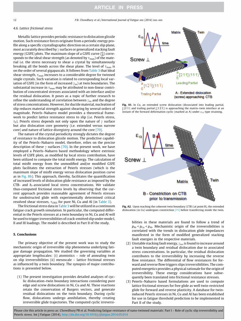
Fig. A2. Upon reaching the coherent twin boundary (CTB) (at point B), the extendeddislocation (in Cu) undergoes constriction [71] before transferring inside the twin.
Fig. A1. In Cu, an extended screw dislocation (dissociated into leading partial,a6 ½2 �11� and trailing partial a
6 ½1 �2 �1�) is approaching the matrix–twin interface at aninstant of the forward deformation cyclic (marked as A) under e13 type straining.
12 P.B. Chowdhury et al. / International Journal of Fatigue xxx (2014) xxx–xxx
4.6. Lattice frictional stress
Metallic lattice provides periodic resistance to dislocation glissilemotion. Such resistance forces originate from a periodic energy pro-file along a specific crystallographic direction on a certain slip plane,most accurately described by c surfaces or generalized stacking faultenergy (GSFE) plots. The maximum slope of a GSFE curve (dc
dx) corre-sponds to the ideal shear strength (as denoted by smax) of the mate-rial i.e. the stress necessary to shear a crystal by simultaneouslybreaking all the bonds across the shear plane. The level of smax ison the order of several gigapascals. It follows from Table 3 that Idealshear strength, smax increases to a considerable degree for twinnedsingle crystals. Such variation is related to corresponding local var-iation of GSFE (in the form of increased cus) at twin boundaries. Thesubstantial increase in smax may be attributed to non-linear contri-bution of concentrated stresses associated with an interface and/orthe residual dislocation. It poses as a topic of further research torefine the understanding of correlation between cus and the degreeof stress concentrations. However, for ductile material, nucleation ofslip reduces material strength against shearing by several orders ofmagnitude. Peierls–Nabarro model provides a theoretical frame-work to predict lattice resistance stress to slip (i.e. Peierls stress,sP). Peierls stress depends not only upon the nature of c surfacebut also dislocation core geometry (i.e. extended versus narrowcore) and nature of lattice disregistry around the core [70].
The nature of the crystal periodicity strongly dictates the degreeof resistance to dislocation glissile motion. The predictive capabil-ity of the Peierls–Nabarro model, therefore, relies on the precisedescription of these c surfaces [70]. In the present work, we haveemployed a Peierls–Nabarro based methodology where extrinsiclevels of GSFE plots, as modified by local stress contribution, havebeen utilized to compute the total misfit energy. The calculation oftotal misfit energy from the unmodified and/or modified GSFEplots facilitates the extraction of Peierls stresses (which is themaximum slope of misfit energy versus dislocation position curveas in Fig. 8b). This approach, thereby, facilitates the quantificationof increased levels of dislocation glide resistance as imposed by theCTB- and br-associated local stress concentrations. We validatethus-computed frictional stress levels by observing that the cur-rent approach provides reasonable agreement of Peierls stressesfor unobstructed glide with experimentally determined criticalresolved shear stresses, sCRSS for pure Ni, Cu and Al (in Table 3).
The frictional stress data in Table 3 will be utilized in a continuumfatigue crack growth simulation. In particular, the computed differ-ential in the Peierls stresses at a twin boundary in Ni, Cu and Al willbe used to trigger irreversibilities of crack-emitted slip under mode I,II and III loadings. The model is described in Part II of the study.
5. Conclusions
The primary objective of the present work was to study themechanistic origin of irreversible slip phenomena underlying fati-gue damage propagation. We studied the governing variables atappropriate lengthscales: (i) atomistics – role of annealing twinon slip irreversibilities (ii) mesoscale – lattice frictional stressesas influenced by a twin boundary. The synopsis of major contribu-tions is presented below.
(1) The present investigation provides detailed analyses of cyc-lic dislocation–twin boundary interactions considering pureedge and screw dislocations in Ni, Cu and Al. These reactionsretain the conservation of Burgers vectors, and generateresidual dislocations on the twin boundary. During cyclicflow, dislocations undergo annihilation, thereby creatingirreversible glide trajectories. The computed cyclic irreversi-
Please cite this article in press as: Chowdhury PB et al. Predicting fatigue resistaPeierls stress. Int J Fatigue (2014), http://dx.doi.org/10.1016/j.ijfatigue.2014.05
bilities in these materials are found to follow a trend ofpNi < pCu < pAl. Mechanistic origin of the irreversibilities iscorrelated with the trends in dislocation glide impedancesmanifested in the form of modified generalized stackingfault energies in the respective materials.
(2) Unstable stacking fault energy, cus, is found to increase arounda twin boundary and residual dislocation due to associatedstress concentrations. In particular, the residual dislocationcontributes to the irreversibility by increasing the reverseflow resistance. The differential of flow resistances for for-ward and reverse flow triggers slips irreversibilities. The com-puted energetics provides a physical rationale for the origin ofirreversibility. These energy considerations have subse-quently been translated into frictional resistance stresses.
(3) Peierls–Nabarro based formulations are used to computelattice frictional stresses for free glide as well twin-restrictedglide for forward and reverse plasticity. A database for twin-induced Peierls stresses in Ni, Cu and Al has been establishedfor use in fatigue threshold prediction to be implemented inPart II of the study.
nce of nano-twinned materials: Part I – Role of cyclic slip irreversibility and.014
P.B. Chowdhury et al. / International Journal of Fatigue xxx (2014) xxx–xxx 13
Acknowledgements
The support of Honeywell Aerospace Corporation is gratefullyacknowledged. We also acknowledge the use of the parallel com-puting resource, the Taub cluster, at the University of Illinois.
Appendix A. Screw dislocation interacting with twin boundary
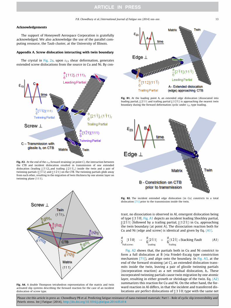
The crystal in Fig. 2a, upon e13 shear deformation, generatesextended screw dislocations from the source in Cu and Ni. By con-
Fig. A3. At the end of the e13 forward straining (at point C), the interaction betweenthe CTB and incident dislocation resulted in transmission of one extendeddislocation (leading a
6 ½�112�T and trailing a6 ½21 �1�T ) inside the twin and a pair of
twinning partials (a6 ½�1 �1 2� and a
6 ½1 �21�) on the CTB. The twinning partials glide awayfrom each other, resulting in the migration of twin thickness by one atomic layer ontwinning plane (111).
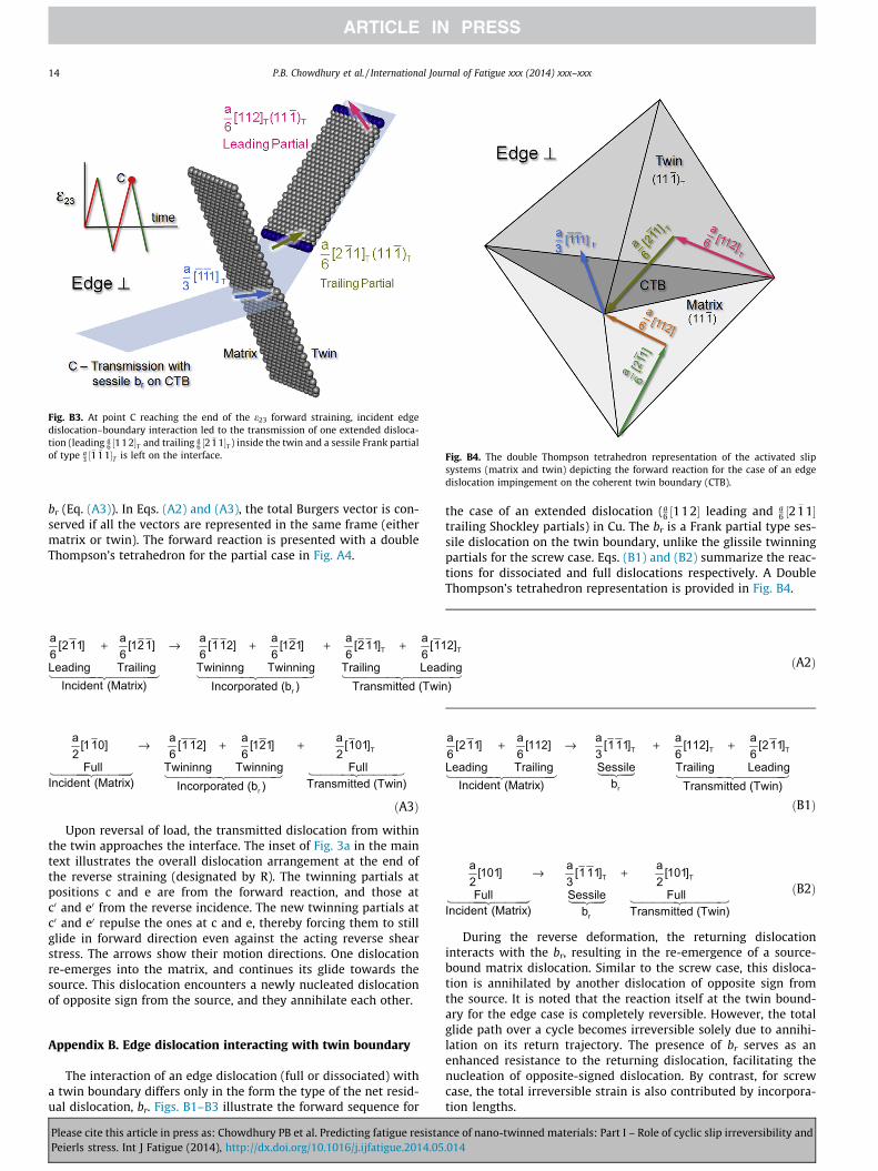
ig. B1. At the loading point A, an extended edge dislocation (dissociated intoading partial, a
6 ½2 �11� and trailing partial a6 ½1 �2 �1�) is approaching the nearest twin
oundary during the forward deformation cyclic under e23 type loading.
Fig. A4. A double Thompson tetrahedron representation of the matrix and twinactivated slip systems describing the forward reaction for the case of an incidentdislocation of screw type.
Please cite this article in press as: Chowdhury PB et al. Predicting fatigue resistaPeierls stress. Int J Fatigue (2014), http://dx.doi.org/10.1016/j.ijfatigue.2014.05
Fleb
Fig. B2. The incident extended edge dislocation (in Cu) constricts to a totaldislocation [71] prior to the transmission inside the twin.
trast, no dissociation is observed in Al, emergent dislocation beingof type a
2 ½1 �10�. Fig. A1 depicts an incident leading Shockley partial,a6 ½2 �11� (followed by a trailing partial, a
6 ½1 �2 �1�) in Cu, approachingthe twin boundary (at point A). The dissociation reaction both forCu and Ni (edge and screw) is identical and given by Eq. (A1).
a2½1 �10�
FullðscrewÞ
! a6½2 �11�
Leading
þ a6½1 �2 �1�
Trailing
þStacking Fault ðA1Þ
Fig. A2 shows that, the partials both in Cu and Ni constrict toform a full dislocation at B (via Friedel–Escaig type constrictionmechanism [71]), and align onto the boundary. In Fig. A3, at theend of the forward straining (at C), an extended dislocation trans-mits inside the twin, leaving a pair of glissile twinning partials(incorporation reaction) as a net residual dislocation, br. Theseincorporated twinning partials cause twin migration by one atomiclayer, resulting in either growth or shrinkage of the twin. Eq. (A2)summarizes this reaction for Cu and Ni. On the other hand, the for-ward reaction in Al differs, in that the incident and transferred dis-locations are perfect dislocations of a
2 ½1 �10� type with the same net
nce of nano-twinned materials: Part I – Role of cyclic slip irreversibility and.014
Fig. B3. At point C reaching the end of the e23 forward straining, incident edgedislocation–boundary interaction led to the transmission of one extended disloca-tion (leading a
6 ½11 2�T and trailing a6 ½2 �1 1�T ) inside the twin and a sessile Frank partial
of type a3 ½�1 �1 1�T is left on the interface. Fig. B4. The double Thompson tetrahedron representation of the activated slip
systems (matrix and twin) depicting the forward reaction for the case of an edgedislocation impingement on the coherent twin boundary (CTB).
14 P.B. Chowdhury et al. / International Journal of Fatigue xxx (2014) xxx–xxx
br (Eq. (A3)). In Eqs. (A2) and (A3), the total Burgers vector is con-served if all the vectors are represented in the same frame (eithermatrix or twin). The forward reaction is presented with a doubleThompson’s tetrahedron for the partial case in Fig. A4.
T T
r
a a a a a a[211] [121] [112] [121] [211] [112]6 6 6 6 6 6Leading Trailing Twininng Twinning
Incident (Matrix) Incorporated (b )
+ → + + +
Trailing LeadingTransmitted (Twin)
ðA2Þ
T
r
a a a a [110] [112] [121] [101]2 6 6 2
Full Twininng Twinning FulIncident (Matrix) Incorporated (b )
→ + +
l Transmitted (Twin)
ðA3Þ
Upon reversal of load, the transmitted dislocation from withinthe twin approaches the interface. The inset of Fig. 3a in the maintext illustrates the overall dislocation arrangement at the end ofthe reverse straining (designated by R). The twinning partials atpositions c and e are from the forward reaction, and those atc0 and e0 from the reverse incidence. The new twinning partials atc0 and e0 repulse the ones at c and e, thereby forcing them to stillglide in forward direction even against the acting reverse shearstress. The arrows show their motion directions. One dislocationre-emerges into the matrix, and continues its glide towards thesource. This dislocation encounters a newly nucleated dislocationof opposite sign from the source, and they annihilate each other.
Appendix B. Edge dislocation interacting with twin boundary
The interaction of an edge dislocation (full or dissociated) witha twin boundary differs only in the form the type of the net resid-ual dislocation, br. Figs. B1–B3 illustrate the forward sequence for
Please cite this article in press as: Chowdhury PB et al. Predicting fatigue resistaPeierls stress. Int J Fatigue (2014), http://dx.doi.org/10.1016/j.ijfatigue.2014.05
the case of an extended dislocation (a6 ½112� leading and a
6 ½2 �11�trailing Shockley partials) in Cu. The br is a Frank partial type ses-sile dislocation on the twin boundary, unlike the glissile twinningpartials for the screw case. Eqs. (B1) and (B2) summarize the reac-tions for dissociated and full dislocations respectively. A DoubleThompson’s tetrahedron representation is provided in Fig. B4.
T T T
r
a a a a a[211] [112] [111] [112] [211]6 6 3 6 6Leading Trailing Sessile Trailing Leading
bIncident (Matrix) Transmitted (Twin)
+ → + +
ðB1Þ
T T
r
a a a [101] [111] [101]2 3 2
Full Sessile Full Incident (Matrix) b Transmitted (Twin)
→ +ðB2Þ
During the reverse deformation, the returning dislocationinteracts with the br, resulting in the re-emergence of a source-bound matrix dislocation. Similar to the screw case, this disloca-tion is annihilated by another dislocation of opposite sign fromthe source. It is noted that the reaction itself at the twin bound-ary for the edge case is completely reversible. However, the totalglide path over a cycle becomes irreversible solely due to annihi-lation on its return trajectory. The presence of br serves as anenhanced resistance to the returning dislocation, facilitating thenucleation of opposite-signed dislocation. By contrast, for screwcase, the total irreversible strain is also contributed by incorpora-tion lengths.
nce of nano-twinned materials: Part I – Role of cyclic slip irreversibility and.014
P.B. Chowdhury et al. / International Journal of Fatigue xxx (2014) xxx–xxx 15
Appendix C. Supplementary material
Supplementary data associated with this article can be found, inthe online version, at http://dx.doi.org/10.1016/j.ijfatigue.2014.05.014.
References
[1] Suresh S. Fatigue of materials. Cambridge University Press; 1998.[2] Afanasyev KA, Sansoz F. Strengthening in gold nanopillars with nanoscale
twins. Nano Lett 2007;7:2056–62.[3] Chen M, Ma E, Hemker KJ, Sheng H, Wang Y, Cheng X. Deformation twinning in
nanocrystalline aluminum. Science 2003;300:1275–7.[4] Kulkarni Y, Asaro RJ. Are some nanotwinned fcc metals optimal for strength,
ductility and grain stability? Acta Mater 2009;57:4835–44.[5] Lu L, Schwaiger R, Shan ZW, Dao M, Lu K, Suresh S. Nano-sized twins induce
high rate sensitivity of flow stress in pure copper. Acta Mater 2005;53:2169–79.
[6] Sangid MD, Pataky GJ, Sehitoglu H, Rateick RG, Niendorf T, Maier HJ. Superiorfatigue crack growth resistance, irreversibility, and fatigue crack growth-microstructure relationship of nanocrystalline alloys. Acta Mater 2011;59:7340–55.
[7] Singh A, Tang L, Dao M, Lu L, Suresh S. Fracture toughness and fatigue crackgrowth characteristics of nanotwinned copper. Acta Mater 2011;59:2437–46.
[8] Jin ZH, Gumbsch P, Ma E, Albe K, Lu K, Hahn H, et al. The interactionmechanism of screw dislocations with coherent twin boundaries in differentface-centred cubic metals. Scripta Mater 2006;54:1163–8.
[9] Mahajan S, Chin GY. Twin–slip, twin–twin and slip–twin interactions in Co–8 wt.% Fe alloy single crystals. Acta Metall 1973;21:173–9.
[10] Remy L. Twin-slip interaction in fcc crystals. Acta Metall 1977;25:711–4.[11] Frenkel D, Smit B, Ratner MA. Understanding molecular simulation: from
algorithms to applications. Phys Today 1997;50:66.[12] Plimpton S. Fast parallel algorithms for short-range molecular dynamics. J
Comput Phys 1995;117:1–19.[13] Tadmor EB, Miller RE. Modeling materials: continuum, atomistic and
multiscale techniques. Cambridge University Press; 2011.[14] Mishin Y, Mehl MJ, Papaconstantopoulos DA, Voter AF, Kress JD. Structural
stability and lattice defects in copper: ab initio, tight-binding, and embedded-atom calculations. Phys Rev B 2001;63:224106.
[15] Foiles SM, Hoyt JJ. Computation of grain boundary stiffness and mobility fromboundary fluctuations. Acta Mater 2006;54:3351–7.
[16] Mishin Y, Farkas D, Mehl MJ, Papaconstantopoulos DA. Interatomic potentialsfor monoatomic metals from experimental data and ab initio calculations.Phys Rev B 1999;59:3393.
[17] Zhou M. A new look at the atomic level virial stress: on continuum-molecularsystem equivalence. Proc Roy Soc Lond A: Math Phys Eng Sci 2003;459:2347–92.
[18] Humphrey W, Dalke A, Schulten K. VMD: visual molecular dynamics. J MolGraph 1996;14:33–8.
[19] Li J. AtomEye: an efficient atomistic configuration viewer. Modell Simul MaterSci Eng 2003;11:173.
[20] Chowdhury PB, Sehitoglu H, Rateick RG, Maier HJ. Modeling fatigue crackgrowth resistance of nanocrystalline alloys. Acta Mater 2013.
[21] Essmann U. Irreversibility of cyclic slip in persistent slip bands of fatigued purefcc metals. Philos Mag A 1982;45:171–90.
[22] Hirth JP, Lothe J. Theory of dislocations. 2nd ed. New York: McGraw-Hill; 1982.[23] Joos B, Duesbery MS. The Peierls stress of dislocations: an analytic formula.
Phys Rev Lett 1997;78:266–9.[24] Schoeck G. The generalized Peierls–Nabarro model. Philos Mag A 1994;69:
1085–95.[25] Tadmor EB, Miller RE. Modeling materials: continuum, atomistic and
multiscale techniques. Cambridge University Press; 2011.[26] Wang J, Sehitoglu H, Maier HJ. Dislocation slip stress prediction in shape
memory alloys. Int J Plast 2013.[27] Adams MA, Cottrell AH. CXXXI. Effect of temperature on the flow stress of
work-hardened copper crystals. Phil Mag 1955;46:1187–93.[28] Blewitt TH. Deformation of copper single crystals at 300 K and 78 K. Phys Rev
1953;91:1115.[29] Cottrell AH, Stokes RJ. Effects of temperature on the plastic properties of
aluminium crystals. Proc R Soc Lond A 1955;233:17–34.[30] Gottstein G, Kocks UF. Dynamic recrystallization and dynamic recovery in
h111i single crystals of nickel and copper. Acta Metall 1983;31:175–88.[31] Haasen P. Plastic deformation of nickel single crystals at low temperatures.
Phil Mag 1958;3:384–418.[32] Hosford Jr WF, Fleischer RL, Backofen WA. Tensile deformation of aluminum
single crystals at low temperatures. Acta Metall 1960;8:187–99.[33] Howe S, Liebmann B, Lucke K. High temperature deformation of aluminum
single crystals. Acta Metall 1961;9:625–31.[34] Jackson PJ, Basinski ZS. Latent hardening and the flow stress in copper single
crystals. Can J Phys 1967;45:707–35.
Please cite this article in press as: Chowdhury PB et al. Predicting fatigue resistaPeierls stress. Int J Fatigue (2014), http://dx.doi.org/10.1016/j.ijfatigue.2014.05
[35] Jaoul PB. Etude de la forme des courbes de deformation plastique. J Mech PhysSolids 1957;5:95–102.
[36] Kocks UF, Brown TJ. Latent hardening in aluminum. Acta Metall 1966;14:87–98.
[37] Latanision RM, Staehle RW. Plastic deformation of electrochemically polarizednickel single crystals. Acta Metall 1969;17:307–19.
[38] Maddin R, Cottrell AH. LXXXIII. Quench hardening in aluminium singlecrystals. Phil Mag 1955;46:735–43.
[39] Mader S, Seeger A, Leitz C. Work hardening and dislocation arrangement ofFCC single crystals. I. Plastic deformation and slip line studies of nickel singlecrystals. J Appl Phys 1963;34:3368–75.
[40] Seeger A, Diehl J, Mader S, Rebstock H. Work-hardening and work-softening offace-centred cubic metal crystals. Phil Mag 1957;2:323–50.
[41] Staubwasser W. On work-hardening of aluminium-single crystals (99.99%)and its interpretation. Acta Metall 1959;7:43–50.
[42] Thornton PR, Mitchell TE, Hirsch PB. The strain-rate dependence of the flowstress of copper single crystals. Phil Mag 1962;7:337–58.
[43] Windle AH, Smith GC. The effect of hydrogen on the plastic deformation ofnickel single crystals. Metal Sci 1968;2:187–91.
[44] Young FW. On the yield stress of copper crystals. J Appl Phys 1962;33:963–9.[45] Van Swygenhoven H, Derlet PM, Froseth AG. Stacking fault energies and slip in
nanocrystalline metals. Nat Mater 2004;3:399–403.[46] Froseth AG, Derlet PM, Van Swygenhoven H. Dislocations emitted from
nanocrystalline grain boundaries: nucleation and splitting distance. ActaMater 2004;52:5863–70.
[47] Lu G, Kioussis N, Bulatov VV, Kaxiras E. Generalized-stacking-fault energysurface and dislocation properties of aluminum. Phys Rev B 2000;62:3099.
[48] Ogata S, Li J, Yip S. Ideal pure shear strength of aluminum and copper. Science2002;298:807–11.
[49] Shang SL, Wang WY, Wang Y, Du Y, Zhang JX, Patel AD, et al. Temperature-dependent ideal strength and stacking fault energy of fcc Ni: a first-principlesstudy of shear deformation. J Phys: Condens Matter 2012;24:155402.
[50] Siegel DJ. Generalized stacking fault energies, ductilities, and twinnabilities ofNi and selected Ni alloys. Appl Phys Lett 2005;87:121901–3.
[51] Carter CB, Holmes SM. The stacking-fault energy of nickel. Phil Mag1977;35:1161–72.
[52] Stobbs WM, Sworn CH. The weak beam technique as applied to thedetermination of the stacking-fault energy of copper. Phil Mag 1971;24:1365–81.
[53] Rice JR. Dislocation nucleation from a crack tip: an analysis based on thePeierls concept. J Mech Phys Solids 1992;40:239–71.
[54] Feltner CE. The mechanism of prismatic dislocation loop formation incyclically strained aluminium. Phil Mag 1966;14:1219–31.
[55] Mitchell AB, Teer DG. The analysis of dislocation structures in fatiguedaluminium single crystals exhibiting striations. Phil Mag 1970;22:399–417.
[56] Mughrabi H. The cyclic hardening and saturation behaviour of copper singlecrystals. Mater Sci Eng 1978;33:207–23.
[57] Lee TC, Robertson IM, Birnbaum HK. An In Situ transmission electronmicroscope deformation study of the slip transfer mechanisms in metals.Metall Trans A 1990;21:2437–47.
[58] Zhu T, Li J, Samanta A, Kim HG, Suresh S. Interfacial plasticity governs strainrate sensitivity and ductility in nanostructured metals. Proc Natl Acad Sci2007;104:3031–6.
[59] Couzinie JP, Decamps B, Priester L. Interaction of dissociated latticedislocations with a sigma 3 grain boundary in copper. Int J Plast 2005;21:759.
[60] Christian JW, Mahajan S. Deformation twinning. Prog Mater Sci 1995;39:1–157.
[61] Mughrabi H. Cyclic slip irreversibility and fatigue life: a microstructure-basedanalysis. Acta Mater 2013;61:1197.
[62] Pippan R. Dislocation emission and fatigue crack growth threshold. Acta MetallMater 1991;39:255–62.
[63] Pippan R. The condition for the cyclic plastic deformation of the crack tip: theinfluence of dislocation obstacles. Int J Fract 1992;58:305–18.
[64] Shyam A, Milligan WW. A model for slip irreversibility and its effect on thefatigue crack propagation threshold in a nickel-base superalloy. Acta Mater2005;53:835–44.
[65] Mughrabi H. Cyclic slip irreversibilities and the evolution of fatigue damage.Metall Mater Trans B 2009;40:431–53.
[66] Weidner A, Sauzay M, Skrotzki W. Experimental evaluation of the cyclic slipirreversibility factor. Key Eng Mater 2011;465:223–6.
[67] Differt K, Esmann U, Mughrabi H. A model of extrusions and intrusions infatigued metals II. Surface roughening by random irreversible slip. Philos MagA 1986;54:237–58.
[68] Forsyth PJE. Fatigue damage and crack growth in aluminium alloys. ActaMetall 1963;11:703–15.
[69] Mompiou Fdr, Caillard D, Legros M, Mughrabi Hl. In situ TEM observations ofreverse dislocation motion upon unloading in tensile-deformed UFGaluminium. Acta Mater 2012;60:3402–14.
[70] Lu G, Kioussis N, Bulatov VV, Kaxiras E. The Peierls–Nabarro model revisited.Philos Mag Lett 2000;80:675–82.
[71] Escaig B. Cross-slipping process in the fcc structure. J Phys 1968;29:225.
nce of nano-twinned materials: Part I – Role of cyclic slip irreversibility and.014