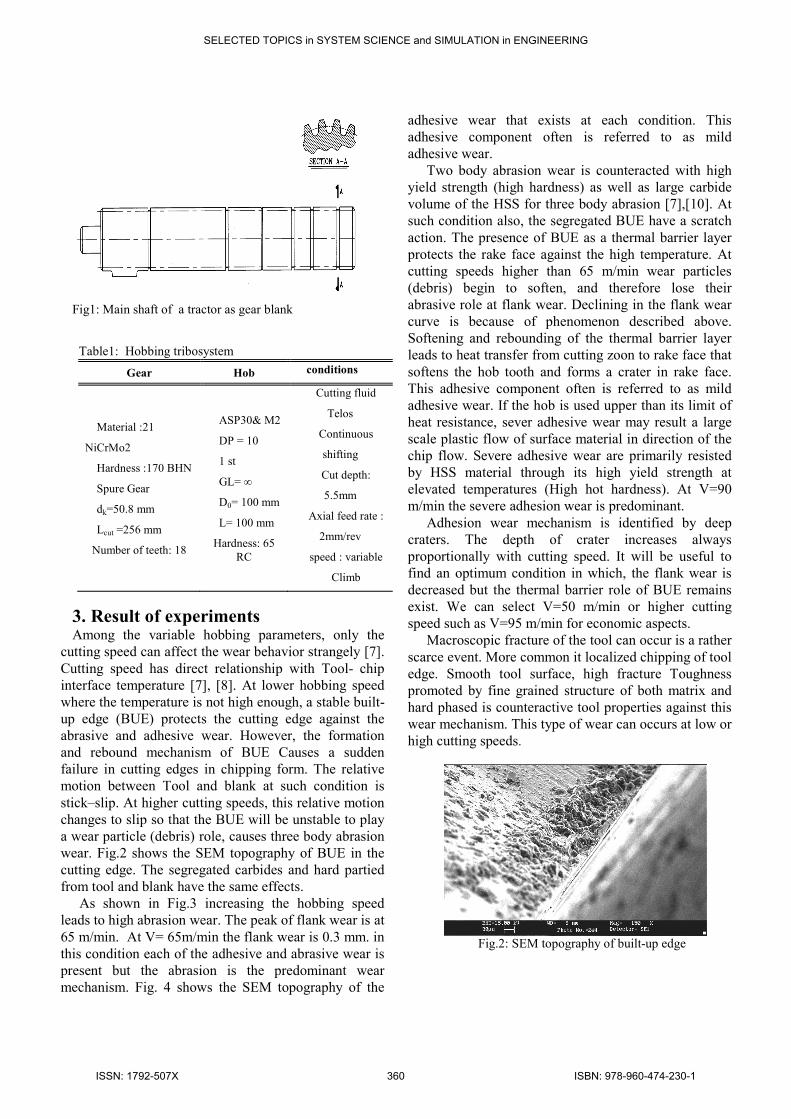
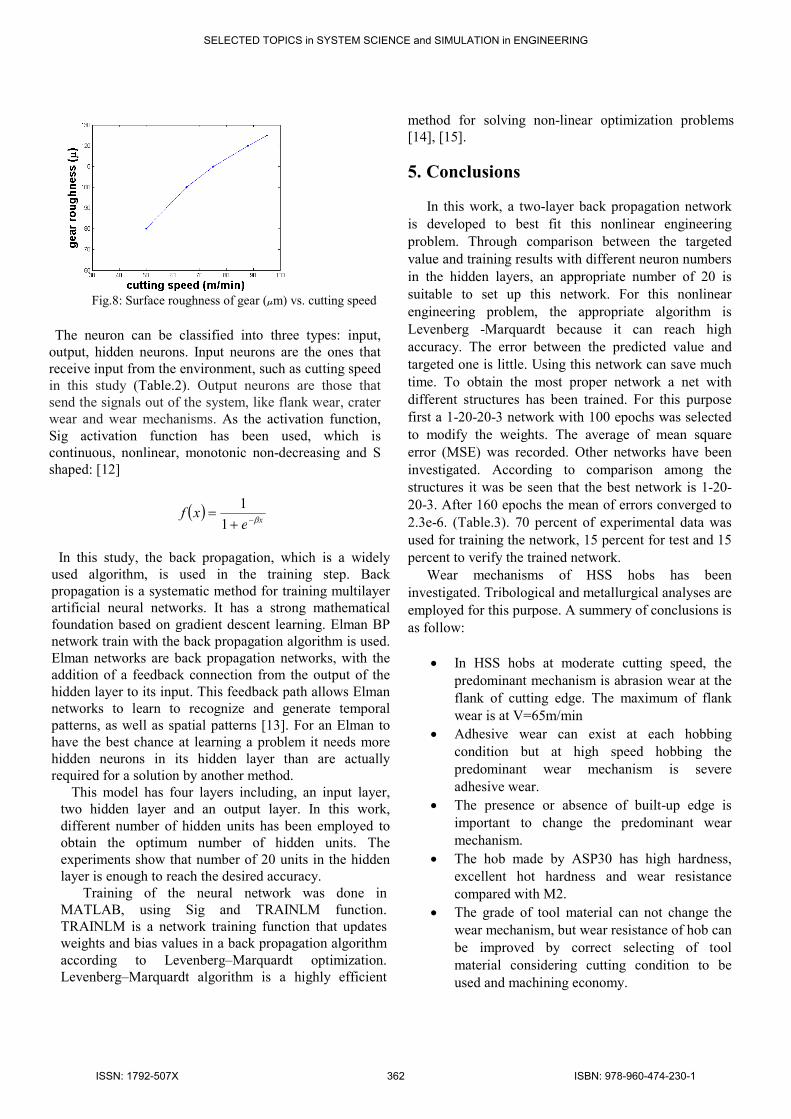
Abstract— In this paper back-propagation artificial neural network (BPANN) is employed to predict the wear of
the gear hobbing tools. The wear of high speed steel hobs during hobbing has been studied. The wear mechanisms
are strongly influenced by the choice of cutting speed. At moderate and high cutting speeds three major wear
mechanisms were identified: abrasion, mild adhesive and severe adhesive. The microstructure and wear behavior of
two high speed steel grades (M2 and ASP30) has been compared. In contrast, a variation in chemical composition or
microstructure of HSS tool material generally did not change the dominant wear mechanism. However, the tool
material properties determine the resistance against the operating wear mechanism and consequently the tool life.
The metallographic analysis and wear measurement at the tip of hob teeth included scanning electron microscopy
and stereoscope microscopy. Comparing experimental and BPANN results, an acceptable correlation was found.
Keywords— Back-propagation artificial neural network abrasion, adhesion, cutting speed, hobbing, wear
mechanism
1. Introduction Gear hobbing is a widely used method in mass gear
production. A hob has a large number of cutting edges
arranged spirally around the tool body. Gear hobbing
remains a cutting technology where high speed steel
continues to find wide application in modern
manufacturing practices [1], [2]. Gear hobbing has
complicated process kinematics; chip formation and
Tool wear mechanisms. Many researchers investigated
the wear behavior and tool life of turning and milling
cutting tools [3]-[6]. To understand the wear
mechanisms in Gear hobbing, it is necessary to have a
brief understanding of the Hobbing tribosystem includes
hob, Gear, Cutting operation and sever contact in the
tool-chip interface. Among the various hobbing
parameters cutting speed has the most effective role on
wear behavior [7].
In this study the effect of cutting parameters on the
wear mechanisms of HSS hobs has been investigated at
industrial conditions. The type of high speed steel
influences the speed that will be used and the wear of
hob. Two grades of HSS (AISI M2 and ASP30) are
selected for this purpose. Moreover back-propagation
artificial neural network (BPANN) is employed to
predict the wear of the gear hobbing tools
2. Experimental procedure The main shaft of a tractor (Fig.1) is selected as gear
blank. Table 1 shows the detail of hob, gear and
hobbing condition. The vertical hobbing machining
Rh6/1623 is used. Cutting speed that has direct
relationship with temperature can change the
predominant wear mechanisms and wear behavior of
hob as well as gear. Scanning electron microscopy
(SEM) was used to study the worn surface and
microstructure. Stereoscope (Nikon-type 104) was used
to measure the flank and crater wear on the flank and
rake face. Surface profilometery is used to measure the
roughness of gear that produced by high speed hobbing
process.
Prediction of Wear Mechanisms in High Speed Steel Hobs Using
Artificial Neural network
M.JALALI AZIZPOUR, H.MOHAMMADI MAJD
PTRI OF ACECR
IRAN
SELECTED TOPICS in SYSTEM SCIENCE and SIMULATION in ENGINEERING
ISSN: 1792-507X 359 ISBN: 978-960-474-230-1
Fig1: Main shaft of a tractor as gear blank
Table1: Hobbing tribosystem
Gear Hob conditions
Material :21
NiCrMo2
Hardness :170 BHN
Spure Gear
dk=50.8 mm
Lcut =256 mm
Number of teeth: 18
ASP30& M2
DP = 10
1 st
GL= ∞
D0= 100 mm
L= 100 mm
Hardness: 65
RC
Cutting fluid
Telos
Continuous
shifting
Cut depth:
5.5mm
Axial feed rate :
2mm/rev
speed : variable
Climb
3. Result of experiments Among the variable hobbing parameters, only the
cutting speed can affect the wear behavior strangely [7].
Cutting speed has direct relationship with Tool- chip
interface temperature [7], [8]. At lower hobbing speed
where the temperature is not high enough, a stable built-
up edge (BUE) protects the cutting edge against the
abrasive and adhesive wear. However, the formation
and rebound mechanism of BUE Causes a sudden
failure in cutting edges in chipping form. The relative
motion between Tool and blank at such condition is
stick–slip. At higher cutting speeds, this relative motion
changes to slip so that the BUE will be unstable to play
a wear particle (debris) role, causes three body abrasion
wear. Fig.2 shows the SEM topography of BUE in the
cutting edge. The segregated carbides and hard partied
from tool and blank have the same effects.
As shown in Fig.3 increasing the hobbing speed
leads to high abrasion wear. The peak of flank wear is at
65 m/min. At V= 65m/min the flank wear is 0.3 mm. in
this condition each of the adhesive and abrasive wear is
present but the abrasion is the predominant wear
mechanism. Fig. 4 shows the SEM topography of the
adhesive wear that exists at each condition. This
adhesive component often is referred to as mild
adhesive wear.
Two body abrasion wear is counteracted with high
yield strength (high hardness) as well as large carbide
volume of the HSS for three body abrasion [7],[10]. At
such condition also, the segregated BUE have a scratch
action. The presence of BUE as a thermal barrier layer
protects the rake face against the high temperature. At
cutting speeds higher than 65 m/min wear particles
(debris) begin to soften, and therefore lose their
abrasive role at flank wear. Declining in the flank wear
curve is because of phenomenon described above.
Softening and rebounding of the thermal barrier layer
leads to heat transfer from cutting zoon to rake face that
softens the hob tooth and forms a crater in rake face.
This adhesive component often is referred to as mild
adhesive wear. If the hob is used upper than its limit of
heat resistance, sever adhesive wear may result a large
scale plastic flow of surface material in direction of the
chip flow. Severe adhesive wear are primarily resisted
by HSS material through its high yield strength at
elevated temperatures (High hot hardness). At V=90
m/min the severe adhesion wear is predominant.
Adhesion wear mechanism is identified by deep
craters. The depth of crater increases always
proportionally with cutting speed. It will be useful to
find an optimum condition in which, the flank wear is
decreased but the thermal barrier role of BUE remains
exist. We can select V=50 m/min or higher cutting
speed such as V=95 m/min for economic aspects.
Macroscopic fracture of the tool can occur is a rather
scarce event. More common it localized chipping of tool
edge. Smooth tool surface, high fracture Toughness
promoted by fine grained structure of both matrix and
hard phased is counteractive tool properties against this
wear mechanism. This type of wear can occurs at low or
high cutting speeds.
Fig.2: SEM topography of built-up edge
SELECTED TOPICS in SYSTEM SCIENCE and SIMULATION in ENGINEERING
ISSN: 1792-507X 360 ISBN: 978-960-474-230-1
Fig. 3: Flank and crater wear vs. cutting speed
Fig.4: SEM topography of adhesion wear mechanisms
Fig.5 shows a micrograph of the microstructure from
ASP30 hobs. Fig.6 shows a micrograph of the
microstructure from AISI M2 steel used as hob material.
As can be seen, the microstructure consists of hard
particles dispersed in a soft matrix. ASP30 that is the
product of Anti Segregation Process has fine carbides as
well as homogeneous distribution of carbides through
the matrix. Then it is difficult for the particles to
segregate from the matrix and hence there will be some
debris at the interface. For this reason, abrasive wear in
M2 hobs is more severe compared with ASP30 hobs
(see Fig.7). High degree of C/V proportion in the
chemical composition (such as M42) leads to a
reduction in the hardness difference between the matrix
and dispersed carbides. It has the same effect on the
abrasion as well as adhesion wear. The critical cutting
speed in M2 hobs is reported to be 60 m/min [11].
The hot hardness of ASP30 hob is because of high
amount of cobalt in the chemical composition. It means
that the ASP30 hobs can be used at high speed hobbing.
Moreover, at high cutting speeds, another wear criterion
exists. Increasing the surface roughness (Fig.8) of the
gear produced at such conditions, limits the cutting
speed to be used. Therefore, for optimizing the cutting
operation it is necessary to consider the surface
roughness of gears as an important criterion. For high
speed hobbing, we may use rigid machine tool and
blanks with low length to diameter (L/D) proportion.
Fig. 5: SEM micrograph of ASP30 hob microstructure
Fig. 6: SEM micrograph of M2 hob microstructure
Fig.7: SEM topography of severe abrasion wear
mechanisms of M2 hob
4. Neural networks An artificial neural network is a parallel distributed
information processing system. It stores the samples
with distributed coding, thus forming a trainable
nonlinear system. The main idea behind a neural
network approach resembles the human brain
functioning. Given the input and the expected outputs,
the program is self adaptive to the environment so as to
respond to different inputs rationally. The objective of
this paper is to investigate the prediction of wear in gear
hobbing, by training a BPANN.
SELECTED TOPICS in SYSTEM SCIENCE and SIMULATION in ENGINEERING
ISSN: 1792-507X 361 ISBN: 978-960-474-230-1
Fig.8: Surface roughness of gear (µm) vs. cutting speed
The neuron can be classified into three types: input,
output, hidden neurons. Input neurons are the ones that
receive input from the environment, such as cutting speed
in this study (Table.2). Output neurons are those that
send the signals out of the system, like flank wear, crater
wear and wear mechanisms. As the activation function,
Sig activation function has been used, which is
continuous, nonlinear, monotonic non-decreasing and S
shaped: [12]
( )xe
xfβ−+
=1
1
In this study, the back propagation, which is a widely
used algorithm, is used in the training step. Back
propagation is a systematic method for training multilayer
artificial neural networks. It has a strong mathematical
foundation based on gradient descent learning. Elman BP
network train with the back propagation algorithm is used.
Elman networks are back propagation networks, with the
addition of a feedback connection from the output of the
hidden layer to its input. This feedback path allows Elman
networks to learn to recognize and generate temporal
patterns, as well as spatial patterns [13]. For an Elman to
have the best chance at learning a problem it needs more
hidden neurons in its hidden layer than are actually
required for a solution by another method.
This model has four layers including, an input layer,
two hidden layer and an output layer. In this work,
different number of hidden units has been employed to
obtain the optimum number of hidden units. The
experiments show that number of 20 units in the hidden
layer is enough to reach the desired accuracy.
Training of the neural network was done in
MATLAB, using Sig and TRAINLM function.
TRAINLM is a network training function that updates
weights and bias values in a back propagation algorithm
according to Levenberg–Marquardt optimization.
Levenberg–Marquardt algorithm is a highly efficient
method for solving non-linear optimization problems
[14], [15].
5. Conclusions
In this work, a two-layer back propagation network
is developed to best fit this nonlinear engineering
problem. Through comparison between the targeted
value and training results with different neuron numbers
in the hidden layers, an appropriate number of 20 is
suitable to set up this network. For this nonlinear
engineering problem, the appropriate algorithm is
Levenberg -Marquardt because it can reach high
accuracy. The error between the predicted value and
targeted one is little. Using this network can save much
time. To obtain the most proper network a net with
different structures has been trained. For this purpose
first a 1-20-20-3 network with 100 epochs was selected
to modify the weights. The average of mean square
error (MSE) was recorded. Other networks have been
investigated. According to comparison among the
structures it was be seen that the best network is 1-20-
20-3. After 160 epochs the mean of errors converged to
2.3e-6. (Table.3). 70 percent of experimental data was
used for training the network, 15 percent for test and 15
percent to verify the trained network.
Wear mechanisms of HSS hobs has been
investigated. Tribological and metallurgical analyses are
employed for this purpose. A summery of conclusions is
as follow:
• In HSS hobs at moderate cutting speed, the
predominant mechanism is abrasion wear at the
flank of cutting edge. The maximum of flank
wear is at V=65m/min
• Adhesive wear can exist at each hobbing
condition but at high speed hobbing the
predominant wear mechanism is severe
adhesive wear.
• The presence or absence of built-up edge is
important to change the predominant wear
mechanism.
• The hob made by ASP30 has high hardness,
excellent hot hardness and wear resistance
compared with M2.
• The grade of tool material can not change the
wear mechanism, but wear resistance of hob can
be improved by correct selecting of tool
material considering cutting condition to be
used and machining economy.
SELECTED TOPICS in SYSTEM SCIENCE and SIMULATION in ENGINEERING
ISSN: 1792-507X 362 ISBN: 978-960-474-230-1
• The error between the predicted value and
targeted one is near to zero and the network can
predict the wear with high accuracy.
Table2: Experimental results
min/m mm
V B
mm
KT Predominant
Wear mechanisms
10 0.05 0.005 Chipping
15 0.05 0.005 Chipping
20 0.08 0.005 Chipping
25 0.09 0.005 Adhesion(BUE)
30 0.1 0.005 Abrasion
35 0.12 0.007 Abrasion
40 0.15 0.01 Abrasion
45 0.17 0.01 Abrasion
50 0.2 0.015 Abrasion
55 0.22 0.02 Abrasion
60 0.25 0.025 Severe abrasion
62 0.25 0.03 Severe abrasion
64 0.28 0.03 Severe abrasion
65 0.3 0.03 Severe abrasion
67 0.27 0.03 Severe abrasion
70 0.25 0.035 Severe abrasion
75 0.23 0.04 Severe abrasion
80 0.21 0.04 Adhesion
85 0.18 0.05 severe adhesion
88 0.13 0.05 severe adhesion
90 0.13 0.05 severe adhesion
95 0.1 0.06 severe adhesion
98 0.1 0.06 severe adhesion
100 0.07 0.07 severe adhesion
Table3: Test conditions
References: [1] Tokawa, T. and Nishimura, Y., "High productivity dry
hobbing system" , Mitsobishi Heavy Industry, Technical
Review, Vol. 38, No.1,PP. 124-147, 2001.
[2] Jainlk, C. and Agreval, G., Metal cutting science and
production technology, McGraw – Hill Publishing company,
NewDelhi, 1988.
[3] Rech, J. and Djouadi, M. and Picot, J., "Wear resistance
of coating in high speed gear hobbing", Wear, Vol. 250, PP. 45-
53, 2001.
[4] Lim, S.C. and Lee, S.H. and Liu, Y.B. "Wear maps for
uncoated high speed steel cutting tools", Wear, Vol. 170,
PP.137-134, 1993.
[5] Scherge, M. and shakhvorostove, "Fundamental of wear
mechanisms of metal", Wear, Vol. 255, PP. 395-400, 2003.
[6] Haron, O. and subramanian, S.V., " Tribology of tool-chip
interface and tool wear mechanisms", Surface and Coatings
Technology, Vol. 149, PP. 151-160, 2001.
[7] Soderberg, S. and Hogmark, S., "Wear mechanisms and tool
life of high speed steels related to microstructure", Wear,
Vol. 110, PP. 315-329 ,1985.
[8] Brion, J.M., "Mechanisms of built-up layer formation on
turning tools: Influence of tool and workpiece", Wear,
Vol.154, PP. 225-239, 1992.
[9] Bhattacharyya, A., Metal Cutting Theory and Practice,
Jadavpur University, New Central Book Agancy, Calcutta,
1998.
[10] EL-Rakayby, A. M. and Mills, B., "the role of primary
carbides in the wear of high speed steel",Wear, Vol. 112, PP.
327-340, 1986.
[11] Joseph, R., ASM Handbook,Vol. 16: Machining, American
Society for Metals, 9th Edition, 1998.
[12] H. Mohammadi Majd, M. Poursina, K. H. Shirazi,"
Determination of barreling curve in upsetting process by
artificial neural networks", 9th WSEAS international
conference on Simulation, modelling and optimization,
Budapest, Hungary, 2009, pp 271-274
[13] Elman, J. L., "Finding structure in time", Cognitive
Science, vol. 14, pp.179-211,1990.
[14] J.SI," theory and application of supervised learning method
based on gradiant algorithms", J tsinghau univ.vol 37,1997.
[15]M.T.HAGEN,"training feed forward network with the
levenberg-marquardt algorithm", IEEE, pp 989-993, 1994
Network
output
BV
Network
output
TK
Crater wear
TK
Flank
wear
BV
cut
speed
(input)
0.0365 -0.00378 0.005 0.05 10
0.0798 0.004054 0.005 0.08 20
0.99 0.006915 0.005 0.10 30
0.1305 0.008219 0.010 0.15 40
0.18 0.018519 0.015 0.20 50
0.24 0.023029 0.025 0.25 60
0.29 0.034289 0.035 0.25 70
0.3 0.043573 0.040 0.21 80
0.15 0.049961 0.050 0.130 90
0.09 0.0699 0.070 0.070 100
SELECTED TOPICS in SYSTEM SCIENCE and SIMULATION in ENGINEERING
ISSN: 1792-507X 363 ISBN: 978-960-474-230-1