Petroleum & Coal ISSN 1337-7027 Available online at www,vurup,skfpc Petroleum & Coal 50 (3), 67-73, 2008 PREDICTIVE TOOL FOR BOTTOM-HOLE PRESSURE IN MULTIPHASE FLOWING WELLS Adekomaya Olufemi 1 , Fadairo AS. Adesina 2 , Falode Olugbenga 3 1Department of Petroleum Engineering, University of Ibadan Nigeria, ([email protected], 2Department of Petroleum Engineering, Covenant University, Ota, Nigeria, 3Department of Petroleum Engineering, University of Ibadan Nigeria Received JUly 1, 2008, accepted September 5, 2008 Abstract The analytical model for predicting the pressure at any point in a flow string is essential in determining optimum production string dimension and in the design of gas-lift installations. This information is also invaluable In predicting bottom-hole pressure in flowing wells. A variety of model on bottom-hole pressure in flowing wells have been reported in the literatures. Most of the early models on pressure drop in the flowing wells were based on single phase flowing wells, even the recent investigators treated the multiphase (liquid and gas phase) as a homogenous single phase flow without accounting for dissolved gas in oil. This paper present a modification of Sukkar and Cornell model for single phase flowing gas wells and the model was adapted to predict the pressure drop in multiphase flowing wells. The key operational and f1uid/ pipe parameters which influence the degree of pressure drop in flowing wells are identified through the modification. !<ey words: modelling; pressure drop; multiphase flow; flowing well 1. Introduction The simultaneous flow of oil, water and gas in vertical pipe is encountered in many engineering installations. In petroleum, chemical process, nuclear engineering and many other industries, problems associated with simultaneous flow of two or more phases through vertical pipe have been of interest for a long time [1- 8 1. This interest has increased considerably during recent years due to applications to new processes in petroleum production and refining. One prominent example of vertical two phase flow is provided by the gas lift process where oil, water and gas flow simultaneously [1J. If the pressure profile in a gas-lift well can be predicted within reasonably accuracy, it would be possible to get good estimates of the power required to lift the oil, the optimum depth pressure and the rate at which to inject gas [1 J • Furthermore, the effect of production rate and tUbing sizes on these quantities can be evaluated before any design decision is made on the installations and operation of the flow string. Studies on multiphase flow in vertical pipe have sought to develop a technique with which the pressure drop can be calculated. Pressure losses in flow of gas and liquid phase are quite different from those encountered in dry gas phase (single-phase) alone [1-2,4-8,1 -14J. The variance is function of interface and gas slippage during the simultaneous flow of gas and liquid. The interface may be smooth or have varying degrees of roughness, depending on the flow pattern [9-10,14] Therefore, transfer of energy from the gaseous phase to the liqUid phase may take place while energy is lost from the system through the wetting phase at the pipe wall. Such an energy transfer may be either in the form of heat exchange or of acceleration. Some each phase must flow through a smaller area than if it flowed alone, amazingly high pressure losses occur when compared to single-phase flow [9- 14 1, It is important to
Transcript
Petroleum & Coal ISSN 1337-7027
Available online at www,vurup,skfpc Petroleum & Coal 50 (3), 67-73, 2008
PREDICTIVE TOOL FOR BOTTOM-HOLE PRESSURE IN MULTIPHASE FLOWING WELLS
Adekomaya Olufemi1, Fadairo AS. Adesina2
, Falode Olugbenga3
1Department of Petroleum Engineering, University of Ibadan Nigeria, ([email protected], 2Department of Petroleum Engineering, Covenant University,
Ota, Nigeria, 3Department of Petroleum Engineering, University of Ibadan Nigeria
Received JUly 1, 2008, accepted September 5, 2008
Abstract
The analytical model for predicting the pressure at any point in a flow string is essential in determining optimum production string dimension and in the design of gas-lift installations. This information is also invaluable In predicting bottom-hole pressure in flowing wells. A variety of model on bottom-hole pressure in flowing wells have been reported in the literatures. Most of the early models on pressure drop in the flowing wells were based on single phase flowing wells, even the recent investigators treated the multiphase (liquid and gas phase) as a homogenous single phase flow without accounting for dissolved gas in oil. This paper present a modification of Sukkar and Cornell model for single phase flowing gas wells and the model was adapted to predict the pressure drop in multiphase flowing wells. The key operational and f1uid/ pipe parameters which influence the degree of pressure drop in flowing wells are identified through the modification.
!<ey words: modelling; pressure drop; multiphase flow; flowing well
1. Introduction
The simultaneous flow of oil, water and gas in vertical pipe is encountered in many engineering installations. In petroleum, chemical process, nuclear engineering and many other industries, problems associated with simultaneous flow of two or more phases through vertical pipe have been of interest for a long time [1-
81. This interest has increased considerably during recent years due to applications to new processes in petroleum production and refining. One prominent example of vertical two phase flow is provided by the gas lift process where oil, water and gas flow simultaneously [1J. If the pressure profile in a gas-lift well can be predicted within reasonably accuracy, it would be possible to get good estimates of the power required to lift the oil, the optimum depth pressure and the rate at which to inject gas [1 J•
Furthermore, the effect of production rate and tUbing sizes on these quantities can be evaluated before any design decision is made on the installations and operation of the flow string.
Studies on multiphase flow in vertical pipe have sought to develop a technique with which the pressure drop can be calculated. Pressure losses in flow of gas and liquid phase ~two-phase) are quite different from those encountered in dry gas phase (single-phase) alone [1-2,4-8,1 -14J. The variance is function of interface and gas slippage during the simultaneous flow of gas and liquid. The interface may be smooth or have varying degrees of roughness, depending on the flow pattern [9-10,14] Therefore, transfer of energy from the gaseous phase to the liqUid phase may take place while energy is lost from the system through the wetting phase at the pipe wall. Such an energy transfer may be either in the form of heat exchange or of acceleration. Some each phase must flow through a smaller area than if it flowed alone, amazingly high pressure losses occur when compared to single-phase flow [9-
141, It is important to
68 Adekomaya Olufemi et al./Petroleum & Coal 50(3) 67-73 (2008)
note that linear pressure gradients or pressure losses are only appropriate when the vertical flow column consists of a single phase fluid such as liquid. When there is more than the one fluid flowing in the vertical column, such as the presence of solution gas in oil, a radical change takes place. Severe investigators such as Poettmann and Carpenter [l J, and Tek [ll J, Orkiszewsk [2] and Ros [9J have developed model on pressure drop or pressure gradient along the tubing, which might only be approximate soiutions. They may not accurately provide information about pressure conditions at the bottom of the well due to the fluid column consisting of two or more fluid phase. Their models treated the liquid and gas as a homogenous single-phase flow without accounting for dissolved gas in oil.
A methodology which uses a single phase flow model to stimulate multiphase fluid flow system and the mixing rule that correspond to the fluid flow pattern is presented. The formulation also presents methods that incorporate the effects of slippage at the gas-liquid interface, the effect of solution gas in the liquid phases and produced gas specific gravity.
This paper presents a model for predicting the bottom hole flowing pressure (BHFP) in multiphase system, where oil/gas or oil/water/gas are flowing together. The model is a modification to Sukkar and Cornnel's model for dry gas. The modification predicts the bottom hole flowing pressure in multiphase system as function of operational and fluid/pipe parameters. It devised a method of extending a single phase model to be applicable for the multiphase flow system.
2. METHODOLOGY
The analytical expressions derived in this study are based on the following fundamental and general assumptions [1-81
1 Steady-state flow of fluid was considered throughout the process. 2 Change in kinetic energy is small and may be neglected 3 Temperature of system is assumed constant at some average value 4 Friction is also assumed constant over the length of the conduit
2. 1 THE MODEL
Consider the flow of fluid from one arbitrary point to another in a given system. Assuming an idealized flow equation, the basic energy equation associated with now of fluid over the length of the conduit can be given as [6,151:
144 udu 9 fu 2
-dp+--du+ -dz+--OL+Ws=O (1)P 2agc gc 2gcO
Assuming no mechanical work is done on the fluid or by the fluid and change in kinetic energy is negligible. Equation (1) can be reduced to: 144 9 fu 2
- dp + - dz + -- dL = 0 (2)P gc 2gcO
The concept of apparent or average multiphase fluid density is quite useful in characterizing a multiphase fluid mixture. The apparent density of a multiphase mixture is defined observing the "mixing rule" [131•
PIp = PLHL + Pg(1-HL} (3)
Therefore, density of gas (pg) at a point in a vertical pipe at pressure and temperature may be
obtained from the definition of the Gas law as [15,17-18):
2897GgP Pg = ZRT (4)
The density of the liquid (oil and water) is obtained as16:
PL = Poho + Pwhw (5)
{624Go +O.010036Gg Rs Jho 624G h wwPL = B + B (6)
o w
Substituting equations (4) and (6) into (3) to obtain two-phase density
69Adekomaya Olufemi et al.lPetroleum & Coal 50(3) 67-73 (2008)
= ((62.4Go+O·0136G gR s }h o + 62.4Gwhw ) H + 28.97PGg(1-H L} (7) fJ Ip B B L ZRT
o w The velocity of fluid flow at a cross-section of a vertical pipe may be defined as [6J;
U =0.4152q gTZ + 0.000082735BoqL M P02 0 2 (8)
Substituting equation (7) and (8) into equation (2) and converting diameter D (inches) to feet, we have:
[l(144dp
62.4Go + 0.0136GgRs ) 62.4G h] 28.97PGg (1- HJ +wh + w H + ---~----= B 0 B L ZRTo w
T p,[1+G1[(~J +G1~(~}G12Et2illC4{CA2+f\+~~)riX~)-1lrt +1] Where;
C43=C42= Go Gg
667fq 2T2 C1= 9
0 5
The detail of the equation (10) is expressed in appendix A
3. ANALYSIS OF RESULTS
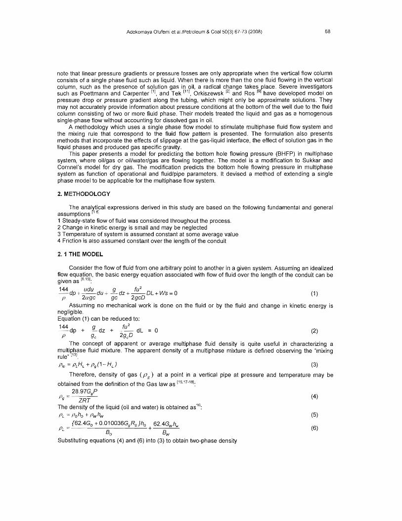
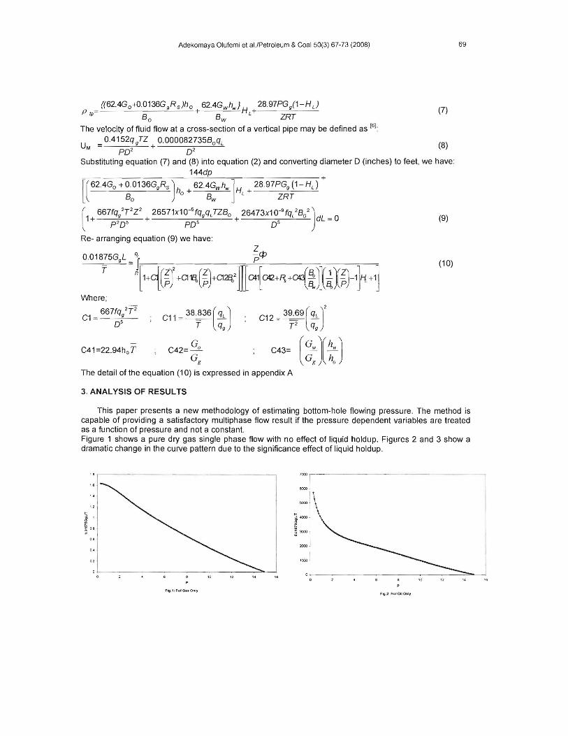
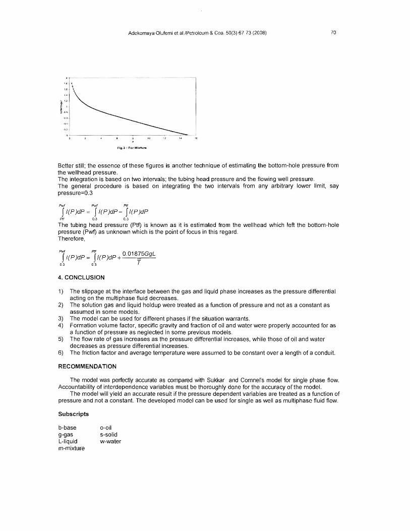
This paper presents a new methodology of estimating bottom-hole flowing pressure. The method is capable of providing a satisfactory mUltiphase flow result if the pressure dependent variables are treated as a function of pressure and not a constant. Figure 1 shows a pure dry gas single phase flow with no effect of liquid holdup. Figures 2 and 3 show a dramatic change in the curve pattern due to the significance effect of liquid holdup.
1.8,------------- ---, 7000
~ 1
~ 08, 0.8
0.<
8000
12 14 " F6g.1:FoIOUOnly
FIg.2: For 011 only
70 Adekomaya Olufemi et al./Petroleum & Coal 50(3) 67-73 (2008)
r: ~ 0.&
Flg.3 : For Mixture
Better still; the essence of these figures is another technique of estimating the bottom-hole pressure from the wellhead pressure. The integration is based on two intervals; the tubing head pressure and the flowing well pressure. The general procedure is based on integrating the two intervals from any arbitrary lower limit. say pressure=O.3
Pwf Pwf Pff
JI(P )dP = JI(P )dP - JI(P )dP Plf 0.3 0.3
The tubing head pressure (Ptt) is known as it is estimated from the wellhead which left the bottom-hole pressure (Pwf) as unknown which is the point of focus in this regard. Therefore,
Ji(P)dP= jl(P)dP+O.01875GgL 03 ~ T
4. CONCLUSION
1) The slippage at the interface between the gas and liquid phase increases as the pressure differential acting on the multiphase fluid decreases.
2) The solution gas and liquid holdup were treated as a function of pressure and not as a constant as assumed in some models.
3) The model can be used for different phases if the situation warrants. 4) Formation volume factor, specific gravity and fraction of oil and water were properly accounted for as
a function of pressure as neglected in some previous models. 5) The flow rate of gas increases as the pressure differential increases, while those of oil and water
decreases as pressure differential increases. 6) The friction factor and average temperature were assumed to be constant over a length of a conduit.
RECOMMENDATION
The model was perfectly accurate as compared with Sukkar and Comnel's model for single phase flow. Accountability of interdependence variables must be thoroughly done for the accuracy of the model.
The model will yield an accurate result if the pressure dependent variables are treated as a function of pressure and not a constant. The developed model can be used for single as well as mUltiphase fluid flow.
ft3 psia. f bblB-formatlon volume actor,- R- gas constant,10.73 0 stb Ib-mole R
D-inside diameter of the pipe, ft T- temperature, oR f-moody friction factor, dimensionless TPR-pseudo reduced temp.
. d . ftg-acce eratlon I ue to gravity, --2 U-average velocity of the fluid, ~ sec sec
. Ibmftgc-converslon factor,32.17 -- V- specific volume of f1uid,.!f..
Ibfs Ibm G-specific gravity, dimensioless Ws-mechanical work done on or by the gas(ws=O) h-volume fraction in the liquid z-gas compressibility factor, dimensionless H-liquid holdup dZ-incremental depth
L-Iength of the f1owstring, ft(for a vertical f1owstring, udu d d ..---pressure rop ue to kinetic energy L=Z) 2ag c
2 fu dl d d f" ffM-molecular weigh of air, 28.97G -- -pressure rop ue to r1ctlon e ects 2g Dc
. IbmP-pressure, psia P = denslty ,-
ft°
a -correction factor to compensate for the variation dp-pressure differential, I~ ft of velocity over the tube cross-section
REFERENCES [1] Poettmann,F.H.,and Carpenter,P.G. 'Multiphase Flow of Gas, Oil and Water Through Vertical
Strings with Application to the Design of Gas Lift Installation, Drilling and Production Practice'. (1952)257.
[2] Orikiszewski,J 'Predicting Two-Phase Pressure Drop in Vertical Pipe.'JPT (June,1967)829-838. [3] Baxendell,P.B., 'The Calculation of Pressure Gradients in High-Rate Flowing Wells.' Transaction
AIME ([1961)Voi 222;1023. [4] Ros N.C.J. 'Simultaneous Flow of Gas and Liquid as Encountered in Well Tubing.' Transaction
AIME (1961)VOL 222,1037 [5] Guo Boyun, 'An Analytical Model for Gas-Water-Coal particle Flow in coal bed-Methane
Production Well.' Paper SPE 72369,Presented,at the SPE Eastern Regional Meeting held in Canton,Ohio, 17-19 October 2001.
[6] Adekomaya Olufemi" Prediction of flowing bottom hole pressure of wells from the well head" M. Sc thesis, Dept. of Petroleum Engineering, University of Ibadan, Nigeria (2007).
[7] Osman,EAAYOUB,MA and Aggour, MA 'Artificial Neural Network Model for Predicting Bottom Hole Flowing Pressure in Vertical Multiphase Flow.' Paper SPE 93632,Presented at the 14th SPE Middle East Oil and Gas show and Conference held in Bahrain International Exhibition Centre,Bahrain,12-15 March 2005.
[8] George H.Fancher,Jnr and Brown K.E., 'Prediction of Pressure Gradients for MUltiphase Flow in Tubing.' Transaction AIME(1963)Vol 228,59.
[9] Guo Boyun, 'Use of Wellhead-Pressure Data to Establish Well-Inflow Performance Relationship.' Paper SPE 72372 Presented at the SPE Eastern Regional Meeting in Canton,Ohio.17-19 October 2001.
[10] Eaton BA and Knowles C.R, 'The Prediction of Flow Pattems, Liquid Holdup and Pressure Losses Occurring During Continuous Two-phase Flow in Horizontal Pipeline.'JPT (1967),819.
[11] Tek MR., 'Multiphase Flow of Water ,Oil and Natural Gas Through Vertical Flow Strings. 'Transaction AIME(1961)VoI.222,1029,1 035
72 Adekomaya Olufemi et al.lPetroleum & Coal 50(3) 67-73 (2008)
[12] Hagedorn A.R. and Brown K.E. 'Experimental Study of Pressure Gradients Occurring During Continuous Two-Phase Flow in Small Diameter Vertical Conduit.', JPT(April 1965),475
[13] Barrufet A.and Ahmed Rasool and Mohammed, 'Prediction of Bottom hole Flowing Pressure in Multiphase Systems Using Thermo-dynamic Equation of State's 29479 Presented at the 1995 SPE Production Operation held in Oklahoma,ApriI2-4,1995.
[14] Faruk Civan, 'Including Non-Equilibrium Effects in Model for Rapid Multiphase Flow in Wells', Paper SPE Annual Technical Conference and Exhibition held in Houston ,USA,26-29 September,2004.
[15] Ikoku 'Natural Gas Engineering Handbook'.pg 310-345. [16] Bharath Rao 'Coiled Tubing Hydraulics Modeling'.(May 10 1999),pg 15-17. [17] Culiender,M.H and R.v.Smith. "Practical Solution of Gas -Flow Equation for Wells and Pipelines
with Large Temperature Gradients."Trans. AIME 207 pp 281-87,1956 [18] Sukkar .Y.K., and D "Direct Calculation of Bottom hole Pressures in Natural Gas
Wells."Trans.AIME 204,PP43-8,1955
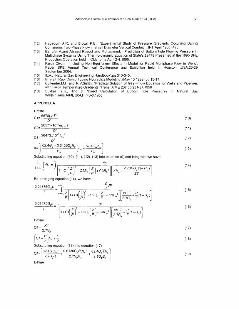
APPENDIX A
Define 2
C1= 667fq/T (10)0 5
C2= 26571x1 O-SfqgqJ (11 )OS
C3= 26473x10-9
fqL2 (12)OS
62.4Go .<-0.0136GgRs] 62.4G h ]X= h + w w (13)[( B 0 Bwo
Substituting equation (10), (11), (12), (13) into equation (9) and integrate, we have
-l-fdL=PJ 2 dp . (14)
144 0 Pl[1+C1(~) +C2B (~)+C3B 2][XH + 2.70PGg(1-HL)1pOp 0 L ZT I
J
Re-arranging equation (14), we have Z
0.01875G gL = PI' pdP (15)
T PPR'i[1.<-C1(iJ +C2Bo(i)+C3Bo2J[:'~~+~(1-HL)] 0.01875GgL = f dP
(16)
T [1+C1(iJ +C2Bo(i)+C3B0 2][:.~~ +~(1-HL)]
Define
C4=~ (17)2.7Gg
C4-~]H +~ (18)[ Z ZL
Substituting equation (13) into equation (17)
62.4Goh T 0.0136GgRS hoT 62.4G Th ]C4= 0 + + w w (19)[ 2.7GgBo 2.7GgBo 2.7GgBw
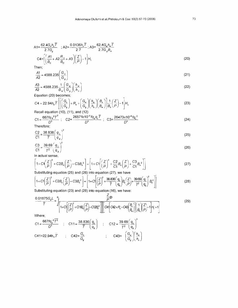
Define
73 Adekomaya Olufemi et al.lPetroleum & Coal 50(3) 67-73 (2008)