333

© Copyright Brother 1999
All rights reserved.
No part of this publication may be reproduced in any form or by any means without permissionin writing from the publisher.
Specifications are subject to change without notice.
Trademarks:
The brother logo is a registered trademark of Brother Industries, Ltd.
Apple, the Apple Logo, and Macintosh are trademarks, registered in the United States andother countries, and True Type is a trademark of Apple computer, Inc.
Epson is a registered trademark and FX-80 and FX-850 are trademarks of Seiko EpsonCorporation.
Hewlett Packard is a registered trademark and HP Laser Jet is a trademark of Hewlett PackardCompany.
IBM, IBM PC and Proprinter are registered trademarks of International Business MachinesCorporation.
Microsoft and MS-DOS are registered trademarks of Microsoft Corporation.
Windows is a registered trademark of Microsoft Corporation in the U.S. and other countries.
PREFACE
i
PREFACEThis service manual contains basic information required for after-sales service of the laserprinter (hereinafter referred to as "this machine" or "the printer"). This information is vital to theservice technician to maintain the high printing quality and performance of the printer.
This service manual covers the HL-1240/1250 printers.
This manual consists of the following chapters:
CHAPTER 1: GENERALFeatures, specifications, etc.
CHAPTER 2: INSTALLATION AND BASIC OPERATIONInstallation conditions, Installation procedures, basic operation of the printeretc.
CHAPTER 3: THEORY OF OPERATIONBasic operation of the mechanical system, the electrical system and theelectrical circuits and their timing information.
CHAPTER 4: DISASSEMBLY AND RE-ASSEMBLYProcedures for disassembling and re-assembling the mechanical system.
CHAPTER 5: MAINTENANCEPeriodical replacements parts, consumable parts, etc.
CHAPTER 6: TROUBLESHOOTINGReference values and adjustments, troubleshooting image defects,troubleshooting malfunctions, etc.
APPENDICES : Serial No. descriptions, Drum life & page counter, Diameter / circumferenceof rollers, Connection diagrams, PCB circuit diagrams, etc.
Information in this manual is subject to change due to improvement or redesign of the product.All relevant information in such cases will be supplied in service information bulletins(Technical Information).
A thorough understanding of this printer, based on information in this service manual andservice information bulletins, is required for maintaining its print quality performance and forimproving the practical ability to find the cause of problems.
TABLE OF CONTENTS
ii
TABLE OF CONTENTS
REGULATION ............................................................................................. vii
SAFETY INFORMATION ............................................................................. ix
CHAPTER 1 GENERAL...........................................................................1-1
1. FEATURES................................ ................................ ................................ ..............1-1
2. OVERVIEW ................................ ................................ ................................ .............1-3
3. SPECIFICATIONS................................ ................................ ................................ ...1-4
3.1 Printing..............................................................................................................................1-4
3.2 Functions ..........................................................................................................................1-4
3.3 Electrical and Mechanical .................................................................................................1-5
3.4 Paper ................................................................................................................................1-63.4.1 Feedable paper................................................................................................................... 1-6
3.4.2 Paper cassette capacity...................................................................................................... 1-7
3.4.3 Print delivery ....................................................................................................................... 1-8
3.5 Printing Area .....................................................................................................................1-83.5.1 Effective printing area ......................................................................................................... 1-8
3.5.2 Print guaranteed area ......................................................................................................... 1-9
CHAPTER 2 INSTALLATION AND BASIC OPERATION.......................2-1
1. CONDITIONS REQUIRED FOR INSTALLATION................................ ....................2-1
1.1 Power Supply....................................................................................................................2-1
1.2 Environment......................................................................................................................2-1
1.3 System Requirements for Brother Printer Solution for Windows®.....................................2-1
2. UNPACKING ................................ ................................ ................................ ...........2-2
3. INSTALL THE PRINTER................................ ................................ .......................... 2-3
3.1 For Windows® Users .........................................................................................................2-3
3.2 For Windows® Users with No CD-ROM Drive...................................................................2-53.2.1 Install the drum unit............................................................................................................. 2-5
3.2.2 Load paper.......................................................................................................................... 2-5
3.2.3 Print a test page.................................................................................................................. 2-5
3.2.4 Connect the printer and the computer ................................................................................ 2-6
3.2.5 Install the printer driver from floppy disk ............................................................................. 2-6
3.3 Using the USB Interface (For Windows® 98 only) .............................................................2-73.3.1 Connect the USB interface cable........................................................................................ 2-7
3.3.2 Install the USB driver .......................................................................................................... 2-7
3.3.3 Set the PC printer port ........................................................................................................ 2-9
3.4 For Macintosh (iMac and Power Macintosh) with USB Users Only..................................2-9
4. PAPER HANDLING ................................ ................................ ............................... 2-10
4.1 Load Paper into the Paper Cassette...............................................................................2-10
4.2 Load Paper Manually ......................................................................................................2-10
TABLE OF CONTENTS
iii
4.3 Two Side Printing (Manual Duplexing)............................................................................2-114.3.1 To print on both sides of the paper from the paper cassette ............................................ 2-11
4.3.2 To print on both sides of the paper from the manual feed slot.......................................... 2-12
5. CONTROL PANEL OPERATION................................ ................................ ...........2-13
5.1 Ready (Paper) LED Indications ......................................................................................2-13
5.2 Data (Toner) LED Indications .........................................................................................2-14
5.3 Drum LED Indications .....................................................................................................2-14
5.4 Alarm LED Indications ....................................................................................................2-14
5.5 Control Panel Button Operations ....................................................................................2-15
5.6 Other Control Features ...................................................................................................2-155.6.1 Sleep mode....................................................................................................................... 2-15
5.6.2 Test print mode ................................................................................................................. 2-16
CHAPTER 3 THEORY OF OPERATION.................................................3-1
1. ELECTRONICS ................................ ................................ ................................ .......3-1
1.1 General Block Diagram.....................................................................................................3-1
1.2 Main PCB Block Diagram .................................................................................................3-3
1.3 Main PCB..........................................................................................................................3-51.3.1 ASIC.................................................................................................................................... 3-5
1.3.2 ROM.................................................................................................................................... 3-8
1.3.3 DRAM.................................................................................................................................. 3-9
1.3.4 Optional RAM.................................................................................................................... 3-11
1.3.5 Optional serial I/O ............................................................................................................. 3-12
1.3.6 EEPROM........................................................................................................................... 3-12
1.3.7 Reset circuit ...................................................................................................................... 3-13
1.3.8 Engine I/O ......................................................................................................................... 3-14
1.4 Engine PCB ....................................................................................................................3-14
1.5 Power Supply..................................................................................................................3-151.5.1 Low-voltage Power Supply ............................................................................................... 3-15
1.5.2 High-voltage Power Supply............................................................................................... 3-16
2. MECHANICS ................................ ................................ ................................ .........3-17
2.1 Overview of Printing Mechanism ....................................................................................3-17
2.2 Paper Transfer ................................................................................................................3-192.2.1 Paper supply ..................................................................................................................... 3-19
2.2.2 Paper registration.............................................................................................................. 3-19
2.2.3 Paper eject........................................................................................................................ 3-20
2.3 Sensors...........................................................................................................................3-202.3.1 Cover sensors A and B ..................................................................................................... 3-20
2.3.2 Toner sensor..................................................................................................................... 3-21
2.4 Drum Unit........................................................................................................................3-212.4.1 Photosensitive drum ......................................................................................................... 3-21
2.4.2 Primary charger ................................................................................................................ 3-21
2.4.3 Transfer roller.................................................................................................................... 3-21
2.4.5 Cleaner ............................................................................................................................. 3-21
2.5 Toner Cartridge...............................................................................................................3-21
2.6 Print Process...................................................................................................................3-222.6.1 Charging ........................................................................................................................... 3-22
TABLE OF CONTENTS
iv
2.6.2 Exposure stage ................................................................................................................. 3-22
2.6.3 Developing ........................................................................................................................ 3-23
2.6.4 Transfer............................................................................................................................. 3-24
2.6.5 Fixing stage....................................................................................................................... 3-24
CHAPTER 4 DISASSEMBLY AND RE-ASSEMBLY ..............................4-1
1. SAFETY PRECAUTIONS ................................ ................................ ........................4-1
2. DISASSEMBLY FLOW ................................ ................................ ............................ 4-2
3. DISASSEMBLY PROCEDURE................................ ................................ ................4-3
3.1 AC Cord ............................................................................................................................4-3
3.2 Drum Unit..........................................................................................................................4-3
3.3 Paper Cassette .................................................................................................................4-4
3.4 Front Cover .....................................................................................................................4-10
3.5 Top Cover .......................................................................................................................4-11
3.6 Main Cover......................................................................................................................4-12
3.7 Laser Unit........................................................................................................................4-13
3.8 Drive Unit ........................................................................................................................4-14
3.9 Fixing Unit .......................................................................................................................4-17
3.10 Base Plate.......................................................................................................................4-25
3.11 Main PCB ASSY .............................................................................................................4-26
3.12 Lower Tray Relay PCB ASSY (HL-1250 only)................................................................4-26
3.13 Low-voltage Power Supply PCB ASSY ..........................................................................4-27
3.14 Engine PCB ASSY / High-voltage Power Supply PCB ASSY ........................................4-28
3.15 Panel PCB ASSY............................................................................................................4-30
3.16 Solenoid ASSY ...............................................................................................................4-30
3.17 Fan Motor ASSY.............................................................................................................4-33
3.18 Toner Sensor PCB ASSY (Light Emission) ....................................................................4-34
3.19 Toner Sensor PCB ASSY (Light Reception)...................................................................4-34
3.20 Paper Pick-up Roller ASSY ............................................................................................4-35
3.21 Paper Feed Roller ASSY ................................................................................................4-36
4. PACKING ................................ ................................ ................................ ..............4-37
CHAPTER 5 PERIODIC MAINTENANCE ...............................................5-1
1. CONSUMABLE PARTS................................ ................................ ........................... 5-1
1.1 Drum Unit..........................................................................................................................5-1
1.2 Toner Cartridge.................................................................................................................5-2
2. PERIODICAL REPLACEMENT PARTS................................ ................................ ...5-4
3. PERIODICAL CLEANING................................ ................................ ........................5-5
3.1 Cleaning the Printer Exterior.............................................................................................5-5
3.2 Cleaning the Drum Unit.....................................................................................................5-5
3.3 Cleaning the Scanner Window..........................................................................................5-6
3.4 Cleaning the Electrical Terminals .....................................................................................5-6
4. MTBF / MTTR................................ ................................ ................................ ..........5-7

TABLE OF CONTENTS
v
CHAPTER 6 TROUBLESHOOTING........................................................6-1
1. INTRODUCTION ................................ ................................ ................................ .....6-1
1.1 Initial Check ......................................................................................................................6-1
1.2 Warnings for Maintenance Work.......................................................................................6-2
1.3 Identify the Problem..........................................................................................................6-3
2. OPERATOR CALLS & SERVICE CALLS ................................ ................................ 6-4
2.1 Operator Calls...................................................................................................................6-4
2.2 Service Calls .....................................................................................................................6-4
3. ERROR MESSAGES................................ ................................ ............................... 6-6
3.1 Error Messages in the Status Monitor ..............................................................................6-6
3.2 Error Message Printouts ...................................................................................................6-8
4. PAPER PROBLEMS................................ ................................ ................................ 6-9
4.1 Paper Load Problems .......................................................................................................6-9
4.2 Paper Jams.....................................................................................................................6-104.2.1 Clearing the jammed paper............................................................................................... 6-10
4.2.2 Causes & countermeasures.............................................................................................. 6-11
4.3 Paper Feeding Problems ................................................................................................6-12
5. SOFTWARE SETTING PROBLEMS ................................ ................................ .....6-14
6. MALFUNCTIONS................................ ................................ ................................ ...6-18
7. IMAGE DEFECTS................................ ................................ ................................ ..6-23
7.1 Image Defect Examples..................................................................................................6-23
7.2 Troubleshooting Image Defect........................................................................................6-24
7.3 Location of Grounding Contacts .....................................................................................6-417.3.1 Drum unit .......................................................................................................................... 6-41
7.3.2 Printer body & paper cassette........................................................................................... 6-41
8. INCORRECT PRINTOUT ................................ ................................ ......................6-42
9. INSPECTION MODE ................................ ................................ ............................. 6-45
9.1 Test Print Mode...............................................................................................................6-45
9.2 Inspection Mode..............................................................................................................6-46
APPENDICES
1. SERIAL NO. DESCRIPTIONS ................................ ................................ ................ A-1
2. DIAMETER / CIRCUMFERENCE OF ROLLERS................................ .................... A-3
3. PRINT SPEEDS WITH VARIOUS SETTINGS................................ ........................ A-4
4. HOW TO KNOW DRUM UNIT LIFE & PAGE COUNTER ................................ ...... A-5
5. HOW TO USE THE SELF-DIAGNOSTICS TOOLS ................................ ............. A-10
6. NVRAM DEFAULT VALUE ................................ ................................ ................... A-14
7. PAPER CASSETTE INFORMATION (FOR EUROPE ONLY)............................... A-15
8. CONNECTION DIAGRAM, HL-1240................................ ................................ ..... A-16
9. CONNECTION DIAGRAM, HL-1250................................ ................................ ..... A-17
10. MAIN PCB CIRCUIT DIAGRAM, HL-1240 (1/2)................................ .................... A-18
TABLE OF CONTENTS
vi
11. MAIN PCB CIRCUIT DIAGRAM, HL-1240 (2/2)................................ .................... A-19
12. MAIN PCB CIRCUIT DIAGRAM, HL-1250 (1/5)................................ .................... A-20
13. MAIN PCB CIRCUIT DIAGRAM, HL-1250 (2/5)................................ .................... A-21
14. MAIN PCB CIRCUIT DIAGRAM, HL-1250 (3/5)................................ .................... A-22
15. MAIN PCB CIRCUIT DIAGRAM, HL-1250 (4/5)................................ .................... A-23
16. MAIN PCB CIRCUIT DIAGRAM, HL-1250 (5/5)................................ .................... A-24
17. ENGINE PCB CIRCUIT DIAGRAM................................ ................................ ....... A-25
18. LOW-VOLTAGE POWER SUPPLY PCB CIRCUIT DIAGRAM (110 - 120V) ........ A-26
19. LOW-VOLTAGE POWER SUPPLY PCB CIRCUIT DIAGRAM (220 - 240V) ........ A-27
20. HIGH-VOLTAGE POWER SUPPLY PCB CIRCUIT DIAGRAM ............................ A-28
INDEX
REGULATION
vii
REGULATION
LASER SAFETY (110 - 120V MODEL ONLY)
This printer is certified as a Class I laser product under the US Department of Health andHuman Services (DHHS) Radiation Performance Standard according to the RadiationControl for Health and Safety Act of 1968. This means that the printer does not producehazardous laser radiation.
Since radiation emitted inside the printer is completely confined within the protectivehousing and external covers. the laser beam cannot escape form the machine during anyphase of user operation.
FDA REGULATIONS (110 - 120V MODEL ONLY)
The US Food and Drug Administration (FDA) has implemented regulations for laserproducts manufactured on and after August 2, 1976. Compliance is mandatory forproducts marketed in the United States. One of the following labels on the back of theprinter indicates compliance with the FDA regulations and must be attached to laserproducts marketed in the United States.
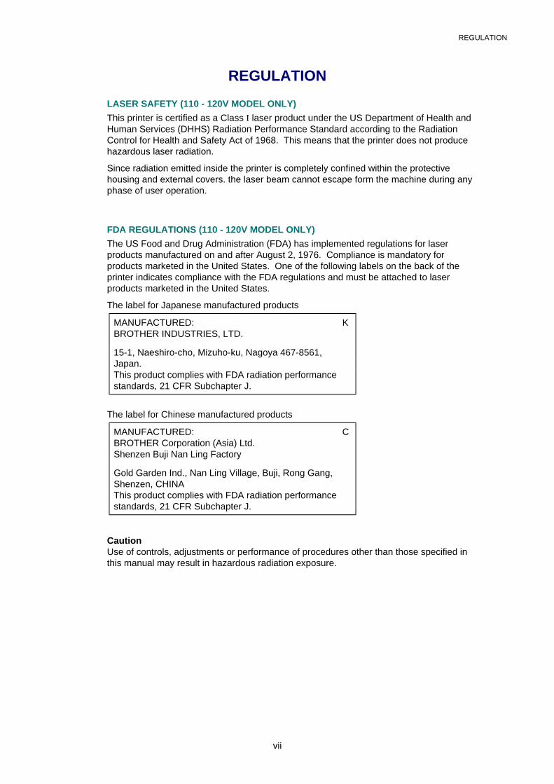
The label for Japanese manufactured products
MANUFACTURED: KBROTHER INDUSTRIES, LTD.
15-1, Naeshiro-cho, Mizuho-ku, Nagoya 467-8561,Japan.This product complies with FDA radiation performancestandards, 21 CFR Subchapter J.
The label for Chinese manufactured products
MANUFACTURED: CBROTHER Corporation (Asia) Ltd.Shenzen Buji Nan Ling Factory
Gold Garden Ind., Nan Ling Village, Buji, Rong Gang,Shenzen, CHINAThis product complies with FDA radiation performancestandards, 21 CFR Subchapter J.
CautionUse of controls, adjustments or performance of procedures other than those specified inthis manual may result in hazardous radiation exposure.
REGULATION
viii
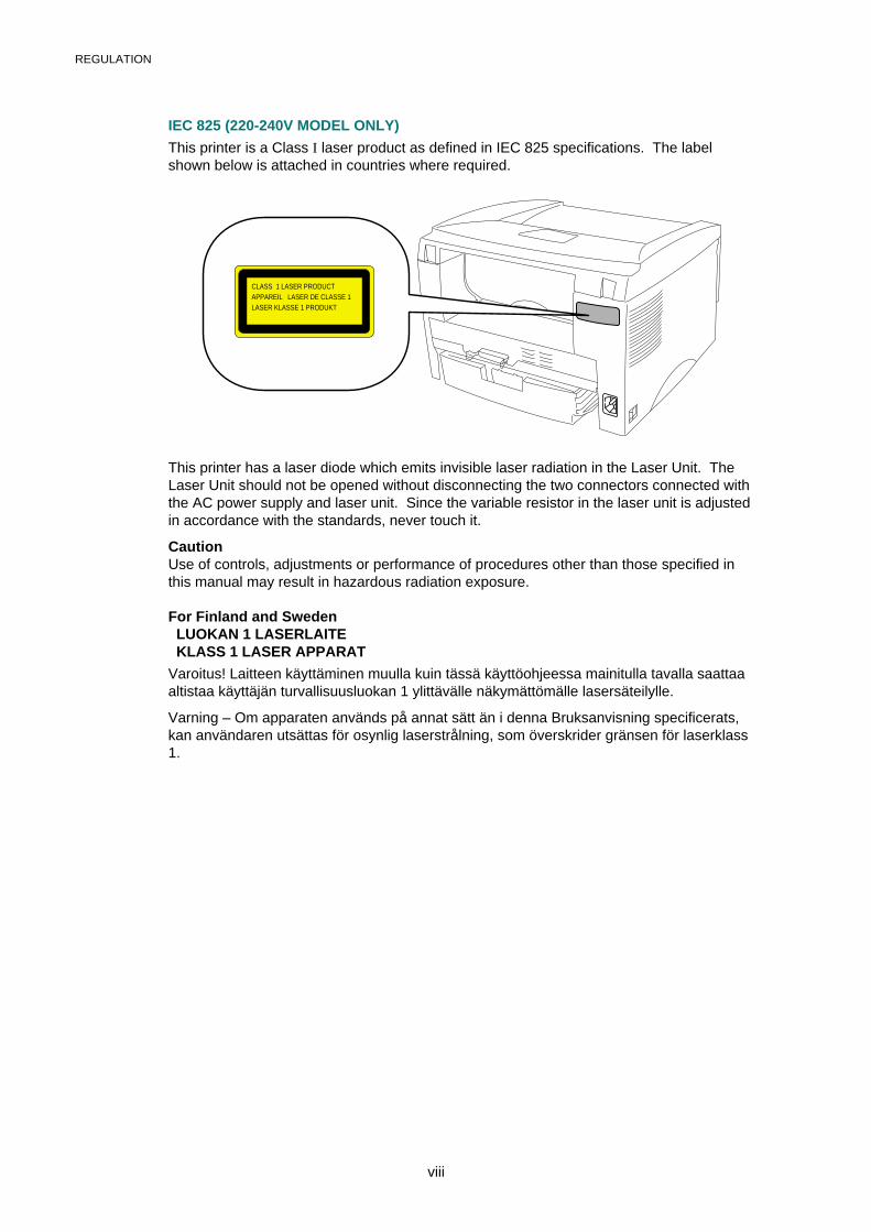
IEC 825 (220-240V MODEL ONLY)
This printer is a Class I laser product as defined in IEC 825 specifications. The labelshown below is attached in countries where required.
CLASS 1 LASER PRODUCTAPPAREIL LASER DE CLASSE 1LASER KLASSE 1 PRODUKT
This printer has a laser diode which emits invisible laser radiation in the Laser Unit. TheLaser Unit should not be opened without disconnecting the two connectors connected withthe AC power supply and laser unit. Since the variable resistor in the laser unit is adjustedin accordance with the standards, never touch it.
CautionUse of controls, adjustments or performance of procedures other than those specified inthis manual may result in hazardous radiation exposure.
For Finland and Sweden LUOKAN 1 LASERLAITE KLASS 1 LASER APPARAT
Varoitus! Laitteen käyttäminen muulla kuin tässä käyttöohjeessa mainitulla tavalla saattaaaltistaa käyttäjän turvallisuusluokan 1 ylittävälle näkymättömälle lasersäteilylle.
Varning – Om apparaten används på annat sätt än i denna Bruksanvisning specificerats,kan användaren utsättas för osynlig laserstrålning, som överskrider gränsen för laserklass1.
SAFETY INFORMATION
ix
SAFETY INFORMATION
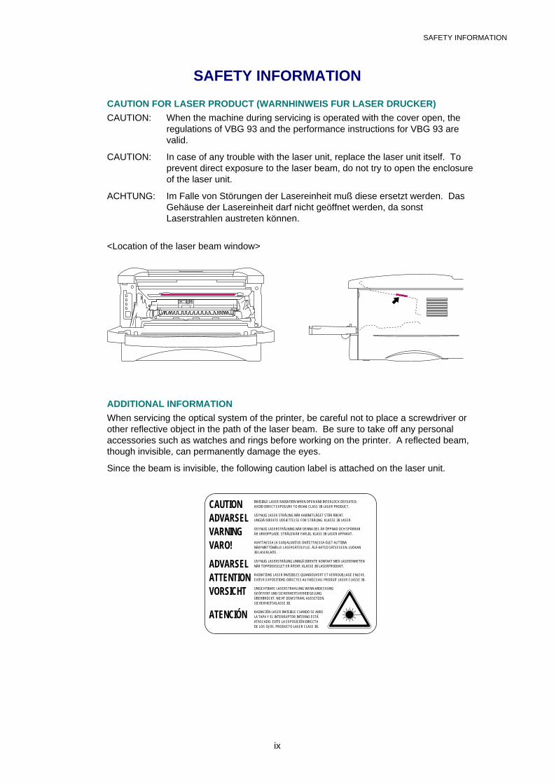
CAUTION FOR LASER PRODUCT (WARNHINWEIS FUR LASER DRUCKER)
CAUTION: When the machine during servicing is operated with the cover open, theregulations of VBG 93 and the performance instructions for VBG 93 arevalid.
CAUTION: In case of any trouble with the laser unit, replace the laser unit itself. Toprevent direct exposure to the laser beam, do not try to open the enclosureof the laser unit.
ACHTUNG: Im Falle von Störungen der Lasereinheit muß diese ersetzt werden. DasGehäuse der Lasereinheit darf nicht geöffnet werden, da sonstLaserstrahlen austreten können.
<Location of the laser beam window>
ADDITIONAL INFORMATION
When servicing the optical system of the printer, be careful not to place a screwdriver orother reflective object in the path of the laser beam. Be sure to take off any personalaccessories such as watches and rings before working on the printer. A reflected beam,though invisible, can permanently damage the eyes.
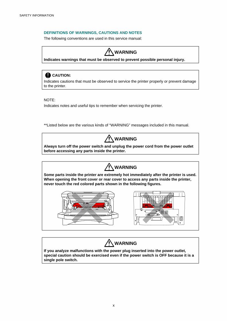
Since the beam is invisible, the following caution label is attached on the laser unit.
CAUTION INVISIBLE LASER RADIATION WHEN OPEN AND INTERLOCK DEFEATED.AVOID DIRECT EXPOSURE TO BEAM. CLASS 3B LASER PRODUCT.
ADVARSEL USYNLIG LASER STRÅLING NÅR KABINETLÅGET STÅR ÅBENT.UNGDÅ DIREKTE UDSÆTTELSE FOR STRÅLING. KLASSE 3B LASER.
VARNING OSYNLIG LASERSTRÅLNING NÄR DENNA DEL ÄR ÖPPNAD OCH SPÄRRARÄR URKOPPLADE. STRÅLEN ÄR FARLIG. KLASS 3B LASER APPARAT.
VARO! AVATTAESSA JA SUOJALUKITUS OHITETTAESSA OLET ALTTIINANÄKYMÄTTÖMÄLLE LASERSÄTEILYLLE. ÄLÄ KATSO SÄTEESEEN. LUOKAN3B LASERLAITE.
ADVARSEL USYNLIG LASERSTRÅLING.UNNGÅ DIREKTE KONTAKT MED LASERENHETENNÅR TOPPDEKSELET ER ÅPENT. KLASSE 3B LASERPRODUKT.
ATTENTION RADIATIONS LASER INVISIBLES QUANDOUVERT ET VERROUILLAGE ENLEVE.EVITER EXPOSITIONS DIRECTES AU FAISCEAU. PRODUIT LASER CLASSE 3B.
VORSICHT UNSICHTBARE LASERSTRAHLUNG WENN ABDECKUNGGEÖFFENT UND SICHERHEITSVERRIEGELUNGÜBERBRÜCKT. NICHT DEM STRAHL AUSSETZEN.SICHERHEITSKLASSE 3B.
ATENCIÓN RADIACIÓN LASER INVISIBLE CUANDO SE ABRELA TAPA Y EL INTERRUPTOR INTERNO ESTÁATASCADO. EVITE LA EXPOSICIÓN DIRECTADE LOS OJOS. PRODUCTO LASER CLASE 3B.
SAFETY INFORMATION
x
DEFINITIONS OF WARNINGS, CAUTIONS AND NOTES
The following conventions are used in this service manual:
WARNING
Indicates warnings that must be observed to prevent possible personal injury.
! CAUTION:
Indicates cautions that must be observed to service the printer properly or prevent damageto the printer.
NOTE:
Indicates notes and useful tips to remember when servicing the printer.
**Listed below are the various kinds of “WARNING” messages included in this manual.
WARNING
Always turn off the power switch and unplug the power cord from the power outletbefore accessing any parts inside the printer.
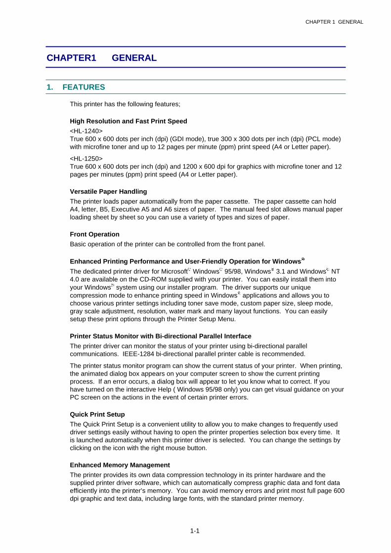
WARNING
Some parts inside the printer are extremely hot immediately after the printer is used.When opening the front cover or rear cover to access any parts inside the printer,never touch the red colored parts shown in the following figures.
WARNING
If you analyze malfunctions with the power plug inserted into the power outlet,special caution should be exercised even if the power switch is OFF because it is asingle pole switch.
CHAPTER 1 GENERAL
1-1
CHAPTER 1 GENERAL
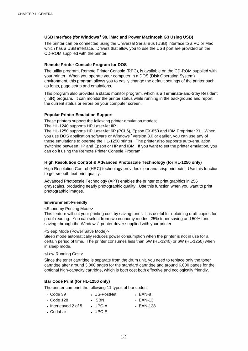
1. FEATURES
This printer has the following features;
High Resolution and Fast Print Speed
<HL-1240>True 600 x 600 dots per inch (dpi) (GDI mode), true 300 x 300 dots per inch (dpi) (PCL mode)with microfine toner and up to 12 pages per minute (ppm) print speed (A4 or Letter paper).
<HL-1250>True 600 x 600 dots per inch (dpi) and 1200 x 600 dpi for graphics with microfine toner and 12pages per minutes (ppm) print speed (A4 or Letter paper).
Versatile Paper Handling
The printer loads paper automatically from the paper cassette. The paper cassette can holdA4, letter, B5, Executive A5 and A6 sizes of paper. The manual feed slot allows manual paperloading sheet by sheet so you can use a variety of types and sizes of paper.
Front Operation
Basic operation of the printer can be controlled from the front panel.
Enhanced Printing Performance and User-Friendly Operation for Windows�
The dedicated printer driver for Microsoft� Windows� 95/98, Windows� 3.1 and Windows� NT4.0 are available on the CD-ROM supplied with your printer. You can easily install them intoyour Windows� system using our installer program. The driver supports our uniquecompression mode to enhance printing speed in Windows� applications and allows you tochoose various printer settings including toner save mode, custom paper size, sleep mode,gray scale adjustment, resolution, water mark and many layout functions. You can easilysetup these print options through the Printer Setup Menu.
Printer Status Monitor with Bi-directional Parallel Interface
The printer driver can monitor the status of your printer using bi-directional parallelcommunications. IEEE-1284 bi-directional parallel printer cable is recommended.
The printer status monitor program can show the current status of your printer. When printing,the animated dialog box appears on your computer screen to show the current printingprocess. If an error occurs, a dialog box will appear to let you know what to correct. If youhave turned on the interactive Help ( Windows 95/98 only) you can get visual guidance on yourPC screen on the actions in the event of certain printer errors.
Quick Print Setup
The Quick Print Setup is a convenient utility to allow you to make changes to frequently useddriver settings easily without having to open the printer properties selection box every time. Itis launched automatically when this printer driver is selected. You can change the settings byclicking on the icon with the right mouse button.
Enhanced Memory Management
The printer provides its own data compression technology in its printer hardware and thesupplied printer driver software, which can automatically compress graphic data and font dataefficiently into the printer’s memory. You can avoid memory errors and print most full page 600dpi graphic and text data, including large fonts, with the standard printer memory.
CHAPTER 1 GENERAL
1-2
USB Interface (for Windows� 98, iMac and Power Macintosh G3 Using USB)
The printer can be connected using the Universal Serial Bus (USB) interface to a PC or Macwhich has a USB interface. Drivers that allow you to use the USB port are provided on theCD-ROM supplied with the printer.
Remote Printer Console Program for DOS
The utility program, Remote Printer Console (RPC), is available on the CD-ROM supplied withyour printer. When you operate your computer in a DOS (Disk Operating System)environment, this program allows you to easily change the default settings of the printer suchas fonts, page setup and emulations.
This program also provides a status monitor program, which is a Terminate-and-Stay Resident(TSR) program. It can monitor the printer status while running in the background and reportthe current status or errors on your computer screen.
Popular Printer Emulation Support
These printers support the following printer emulation modes;The HL-1240 supports HP LaserJet IIP.The HL-1250 supports HP LaserJet 6P (PCL6), Epson FX-850 and IBM Proprinter XL. Whenyou use DOS application software or Windows� version 3.0 or earlier, you can use any ofthese emulations to operate the HL-1250 printer. The printer also supports auto-emulationswitching between HP and Epson or HP and IBM. If you want to set the printer emulation, youcan do it using the Remote Printer Console Program.
High Resolution Control & Advanced Photoscale Technology (for HL-1250 only)
High Resolution Control (HRC) technology provides clear and crisp printouts. Use this functionto get smooth text print quality.
Advanced Photoscale Technology (APT) enables the printer to print graphics in 256grayscales, producing nearly photographic quality. Use this function when you want to printphotographic images.
Environment-Friendly
<Economy Printing Mode>This feature will cut your printing cost by saving toner. It is useful for obtaining draft copies forproof-reading. You can select from two economy modes, 25% toner saving and 50% tonersaving, through the Windows� printer driver supplied with your printer.
<Sleep Mode (Power Save Mode)>Sleep mode automatically reduces power consumption when the printer is not in use for acertain period of time. The printer consumes less than 5W (HL-1240) or 6W (HL-1250) whenin sleep mode.
<Low Running Cost>
Since the toner cartridge is separate from the drum unit, you need to replace only the tonercartridge after around 3,000 pages for the standard cartridge and around 6,000 pages for theoptional high-capacity cartridge, which is both cost both effective and ecologically friendly.
Bar Code Print (for HL-1250 only)
The printer can print the following 11 types of bar codes;
� Code 39 � US-PostNet � EAN-8� Code 128 � ISBN � EAN-13� Interleaved 2 of 5 � UPC-A � EAN-128� Codabar � UPC-E
CHAPTER 1 GENERAL
1-3
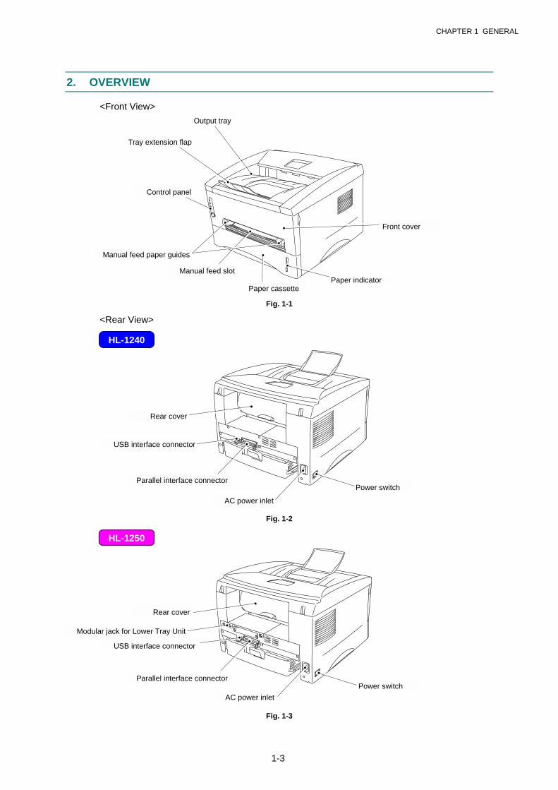
2. OVERVIEW
<Front View>
Fig. 1-1
<Rear View>
Fig. 1-2
Fig. 1-3
HL-1240
HL-1250
Output tray
Manual feed paper guides
Paper cassette
Control panel
Tray extension flap
Front cover
Power switch
Manual feed slot
Rear cover
Paper indicator
USB interface connector
Power switch
Parallel interface connector
Rear cover
AC power inlet
USB interface connector
Modular jack for Lower Tray Unit
AC power inlet
Parallel interface connector

CHAPTER 1 GENERAL
1-4
3. SPECIFICATIONS
3.1 Printing
Print method Electrophotography by semiconductor laser beam scanning
Laser Wave length: 780 nmOutput: 5mW max
Resolution HL-1240: 600 x 600 dots/inch (GDI)300 x 300 dots/inch (under DOS or other operatingsystem)
HL-1250: 1200(H) x 600(V) dots/inch (for Windows� DIBgraphics)600 x 600 dots/inch (for Windows� and DOS)300 x 300 dots/inch (under Apple Macintosh using theoptional RS-100M)
Print quality Normal printing modeEconomy printing mode (up to 25% and 50% toner saving)
Print speed Up to 12 pages/minute*(when loading A4 or Letter-size paper from the paper cassette.)
Warm-up Max. 45 seconds at 23�C (73.4�F)
First print 15 seconds(when loading A4 or Letter-size paper from the paper cassette.)
Print media Toner cartridgeLife expectancy: 3,000 pages/cartridge (Standard cartridge)
6,000 pages/cartridge (High-capacity cartridge)(when printing A4 or Letter-size paper at 5% print coverage)
Developer Drum unitLife expectancy: 20,000 pages/drum unit
*NOTE:
Print speed varies depending on the paper size or media type. For details, refer to APPENDIX3 ‘PRINT SPEEDS WITH VARIOUS SETTINGS’.
3.2 Functions
CPU HL-1240: MB86833 66MHzHL-1250: MB86832 66MHz
Emulation HL-1240: Brother Printing Solution for Windows�
HP LaserJet IIP (PCL level 4)HL-1250: Brother Printing Solution for Windows�
Automatic emulation selection among HP LaserJet 6P(PCL level 6), EPSON FX-850 or IBM Proprinter XL
CHAPTER 1 GENERAL
1-5
Printer driver � Windows� 3.1/3.11, Windows� 95/98, Windows� NT 4.0 driver:supporting Brother Native Compression mode
� Windows� 3.1/3.11, Windows� 95/98 driver: supporting bi-directional capacity
� iMac, Power Macintosh G3 with USB printer driver� Optional Macintosh driver available for System 6.0.7 or higher
(for HL-1250 only)
Interface � Bi-directional parallel� Universal Serial Bus (USB)� Optional RS-422A/RS-232C serial (RS-100M) available (for HL-
1250 only)
Memory HL-1240: 2.0 MbytesHL-1250: 4.0 Mbytes
Expandable up to 36 Mbytes by installing an industrystandard SIMM
Control panel 1 button and 4 LEDs
Diagnostics Self-diagnostic program
3.3 Electrical and Mechanical
Power source U.S.A. and Canada: AC 110 to 120V, 50 Hz/60 HzEurope and Australia: AC 220 to 240V, 50 Hz/60 Hz
Power consumption Printing (peak)*: 940 W or lessPrinting (average): 340 W or lessStanding by: 80 W or lessSleep*: 5 W or less (HL-1240) / 6 W or less (HL-1250)
Noise Printing: 49 dB A or lessStanding by: 27 dB A or less
Temperature Operating: 10 to 32.5�C (50 to 90.5�F)Non operating: 0 to 40�C (38 to 104�F)Storage: -20 to 40�C (-4 to 104�F)
Humidity Operating: 20 to 80% (non condensing)Storage: 10 to 85% (non condensing)
Dimensions A4 paper cassette installed: 360 x 370 x 235 mm(W x D x H) (14.2 x 14.6 x 9.3 inches)
Legal paper cassette installed: 360 x 430 x 235 mm(14.2 x 16.9 x 9.3 inches)
A4 lower paper cassette installed: 360 x 370 x 345 mm(HL-1250 only) (14.2 x 14.6 x 13.6 inches)Legal lower paper cassette installed: 360 x 430 x 345 mm(HL-1250 only) (14.2 x 16.9 x 13.6 inches)
Weight Approx. 9.2 kg (20.2 lb.) including the drum unit.Approx. 12.7 kg (27.9 lb.) including the drum unit and Lower Tray unit.

CHAPTER 1 GENERAL
1-6
*NOTE:
� The peak figure of power consumption is worked out when the halogen heater lamp isturned ON.
� The peak figure of power consumption is worked out excluding inrush current value.
� The peak figure of power consumption is a reference value and should be used internally atBrother offices only.
� The power consumption figure quoted for sleep mode is when the fan has stopped.
3.4 Paper
3.4.1 Feedable paper
(1) Type & size
Feeding source Paper type Paper size
Paper cassette Normal paperTransparencies
A4, Letter, B5 (ISO), A5, A6, Executive, Legal*
Manual feed slot Normal paper A4, Letter, B5 (JIS/ISO), A5, A6, Executive, Legal70-216 x 116-356 mm(2.75-8.5 x 4.57-14 inches)
Envelopes DL, C5, COM10, Monarch, B5 (ISO)
Organizers J, K, L sizes of DAY-TIMER
Labels A4, Letter
Transparencies A4, Letter
Other sizes 70-216 x 116-356 mm (2.75-8.5 x 4.57-14 inches)
Optional lowerpaper cassette( HL-1250 only)
Normal paper
Transparencies
A4, Letter, B5 (ISO), A5, Executive, Legal*
*NOTE:
Legal-size paper can be printed with the standard paper cassette or the optional lower cassettefor the US and Canada models only.
(2) Other paper specifications
<Paper Cassette>
Cut sheet
Basis weight 64 to 105 g/m2 (17 to 28 lb.)
Caliper 0.08 to 0.13 mm (0.003 to 0.005 in.)
Moisture content 4% to 6% by weight
<Manual Feed Slot>
Cut sheet Envelope
Basis weight 64 to 158 g/m2 (17 to 43 lb.) 75 to 90 g/m2 (20 to 24 lb.)single thickness
Caliper 0.08 to 0.2 mm (0.003 to 0.008 in.) 0.084 to 0.14 mm (0.003 to 0.005 in.)single thickness
Moisture content 4% to 6% by weight 4% to 6% by weight
CHAPTER 1 GENERAL
1-7
(3) Recommended paper
� Letter: Xerox 4200 (75 g/m2)� A4: Xerox 80 Premier Paper (80 g/m2)� Label: Avery laser label or equivalent� Transparency: 3M CG3300 or equivalent
! CAUTION:
When you are choosing print media, be sure to follow the information given below to preventany paper jams, print quality problems or printer damage;
� It is recommended to use long-grained paper for the best print quality. If short-grainedpaper is being used, it might be the cause of paper jams.
� Use neutral paper. Do not use acid paper to avoid any damage to the drum unit.
� Avoid using coated paper such as vinyl coated paper.
� Avoid using preprinted or highly textured paper.
� It is recommended to use labels or transparencies which are designed for use in laserprinters.
� Avoid feeding labels with the carrier sheet exposed, or the printer will be damaged.
� Before loading paper with holes such as organizer sheets, be sure to fan the stack well.
� Do not use organizer sheets that are stuck together. The glue that is used might causeddamaged to the printer.
� When printing on the back of pre-printed paper, if the paper is curled, be sure to straightenthe paper as much as possible.
� Different types of paper should not be loaded at the same time in the paper cassette toavoid any paper jams or misfeeds.
3.4.2 Paper cassette capacity
(1) Maximum load height
Paper cassette:
<Normal paper> Up to 27mm (1.06 inches) in height(250 sheets of 80 g/m2 A4/Letter paper)
<Transparencies> 10 sheets
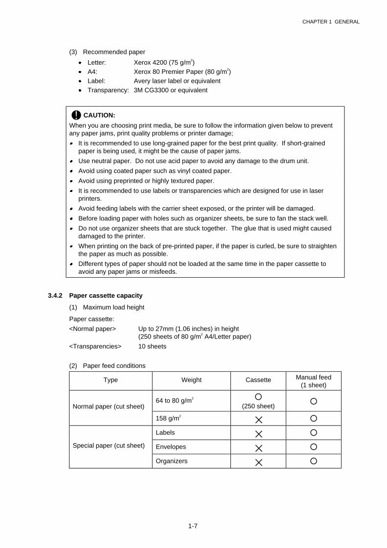
(2) Paper feed conditions
Type Weight Cassette Manual feed(1 sheet)
Normal paper (cut sheet)64 to 80 g/m2 �
(250 sheet)�
158 g/m2
✕ �
Labels ✕ �
Special paper (cut sheet) Envelopes ✕ �
Organizers ✕ �

CHAPTER 1 GENERAL
1-8
3.4.3 Print delivery
(1) Output tray stacking
capacity: Maximum 150 sheets (80 g/m2) face-down only
(2) Straight paper path output at the rear of the printer
capacity: 1 sheet **Thicker paper printing is recommended. face-up only
NOTE:
� When using the straight paper path feed and the rear output method for thicker paperprinting, lift up the rear cover at the rear of the printer.
� Face-down: Delivery with the printed face of the paper downwards.Face-up: Delivery with the printed face of the paper upwards.
3.5 Printing Area
3.5.1 Effective printing area
The effective printing area means the area within which the printing of all the data receivedwithout any omissions can be guaranteed.
4.23mm
4.23mm
208mm
2,400 (80 characters)
25 25
NOTE:� The units in the above figure are dot size
based on 300 dpi resolution.� 25 dots at both sides is for italic characters.
(1) Supported by the engine (2) Supported by the emulation
CHAPTER 1 GENERAL
1-9
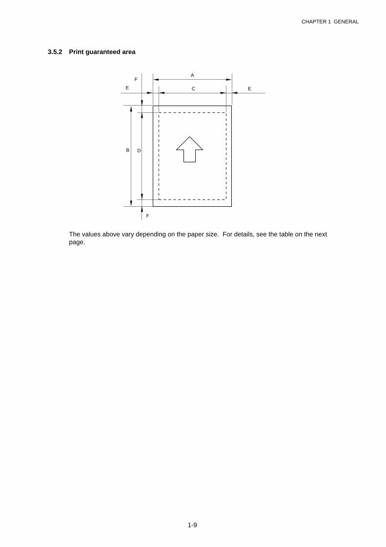
3.5.2 Print guaranteed area
A
E C E
B D
F
F
The values above vary depending on the paper size. For details, see the table on the nextpage.
CHAPTER 1 GENERAL
1-10
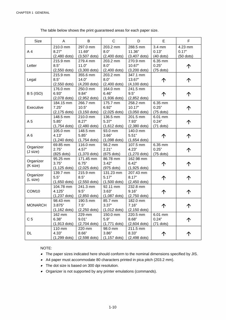
The table below shows the print guaranteed areas for each paper size.
Size A B C D E F
A 4210.0 mm8.27”(2,480 dots)
297.0 mm11.69”(3,507 dots)
203.2 mm8.0”(2,400 dots)
288.5 mm11.36”(3,407 dots)
3.4 mm0.13”(40 dots)
4.23 mm0.17”(50 dots)
Letter215.9 mm8.5”(2,550 dots)
279.4 mm11.0”(3,300 dots)
203.2 mm8.0”(2,400 dots)
270.9 mm10.67”(3,200 dots)
6.35 mm0.25”(75 dots)
�
Legal215.9 mm8.5”(2,550 dots)
355.6 mm14.0”(4,200 dots)
203.2 mm8.0”(2,400 dots)
347.1 mm13.67”(4,100 dots)
� �
B 5 (ISO)176.0 mm6.93”(2,078 dots)
250.0 mm9.84”(2,952 dots)
164.0 mm6.46”(1,936 dots)
241.5 mm9.5”(2,852 dots)
� �
Executive184.15 mm7.25”(2,175 dots)
266.7 mm10.5”(3,150 dots)
175.7 mm6.92”(2,025 dots)
258.2 mm10.17”(3,050 dots)
6.35 mm0.25”(75 dots)
�
A 5148.5 mm5.85”(1,754 dots)
210.0 mm8.27”(2,480 dots)
136.5 mm5.37”(1,612 dots)
201.5 mm7.93”(2,380 dots)
6.01 mm0.24”(71 dots)
�
A 6105.0 mm4.13”(1,240 dots)
148.5 mm5.85”(1,754 dots)
93.0 mm3.66”(1,098 dots)
140.0 mm5.51”(1,654 dots)
� �
Organizer(J size)
69.85 mm2.75”(825 dots)
116.0 mm4.57”(1,370 dots)
56.2 mm2.21”(675 dots)
107.5 mm4.23”(1,270 dots)
6.35 mm0.25”(75 dots)
�
Organizer(K size)
95.25 mm3.75”(1,125 dots)
171.45 mm6.75”(2,025 dots)
86.78 mm3.42”(975 dots)
162.98 mm6.42”(1,925 dots)
� �
Organizer(L size)
139.7 mm5.5”(1,650 dots)
215.9 mm8.5”(2,550 dots)
131.23 mm5.17”(1,500 dots)
207.43 mm8.17”(2,450 dots)
� �
COM10104.78 mm4.125”(1,237 dots)
241.3 mm9.5”(2,850 dots)
92.11 mm3.63”(1,087 dots)
232.8 mm9.16”(2,750 dots)
� �
MONARCH98.43 mm3.875”(1,162 dots)
190.5 mm7.5”(2,250 dots)
85.7 mm3.37”(1,012 dots)
182.0 mm7.16”(2,150 dots)
� �
C 5162 mm6.38”(1,913 dots)
229 mm9.01”(2,704 dots)
150.0 mm5.9”(1,771 dots)
220.5 mm8.68”(2,604 dots)
6.01 mm0.24”(71 dots)
�
DL110 mm4.33”(1,299 dots)
220 mm8.66”(2,598 dots)
98.0 mm3.86”(1,157 dots)
211.5 mm8.33”(2,498 dots)
� �
NOTE:
� The paper sizes indicated here should conform to the nominal dimensions specified by JIS.
� A4 paper must accommodate 80 characters printed in pica pitch (203.2 mm).
� The dot size is based on 300 dpi resolution.
� Organizer is not supported by any printer emulations (commands).
CHAPTER 2 INSTALLATION AND BASIC OPERATION
2-1
CHAPTER 2 INSTALLATION AND BASIC OPERATION
1. CONDITIONS REQUIRED FOR INSTALLATION
1.1 Power Supply
� The source voltage must stay within ±10% of the rated voltage shown on the rating plate.
� The power cord, including extensions, should not exceed 5 meters (16.5 feet).
� Do no share the same power circuit with other high-power appliances, particularly an airconditioner, copier or shredder. If it is unavoidable that you must use the printer with theseappliances, it is recommended that you use an isolation transformer or a high-frequencynoise filter.
� Use a voltage regulator if the power source is not stable.
1.2 Environment
� The printer should be installed near a power outlet, which is easily accessible.
� The room temperature is maintained between 10°C and 32.5°C. The relative humidity ismaintained between 20% and 80%.
� The printer should be used in a well ventilation room.
� Place the printer on a flat, horizontal surface.
� Keep the printer clean. Do not place the printer in a dusty place.
� Do not place the printer where the ventilation hole of the printer is blocked. Keepapproximately 100 mm (4 inches) between the ventilation hole and the wall.
� Do not place the printer where it is exposed to direct sunlight. Use a blind or a heavycurtain to protect the printer from direct sunlight when the printer is unavoidably set up neara window.
� Do not place the printer near devices that contain magnets or generate magnetic fields.
� Do not subject the printer to strong physical shocks or vibrations.
� Do not expose the printer to open flames or salty or corrosive gasses.
� Do not place objects on top of the printer.
� Do not place the printer near an air conditioner.
� Keep the printer horizontal when carrying.
� Do not cover the slots in the side cover.
1.3 System Requirements for Brother Printer Solution for Windows�
Check the following system requirements to setup and operate the printer using BrotherPrinting Solution for Windows:
� IBM PC or compatible with 80486 SX or higher microprocessor
� 10MB of space available on your hard disk for the printer driver and all fonts.
� Microsoft Windows� 3.1/3.11, Windows� 95/98 or Windows� NT 4.0
CHAPTER 2 INSTALLATION AND BASIC OPERATION
2-2
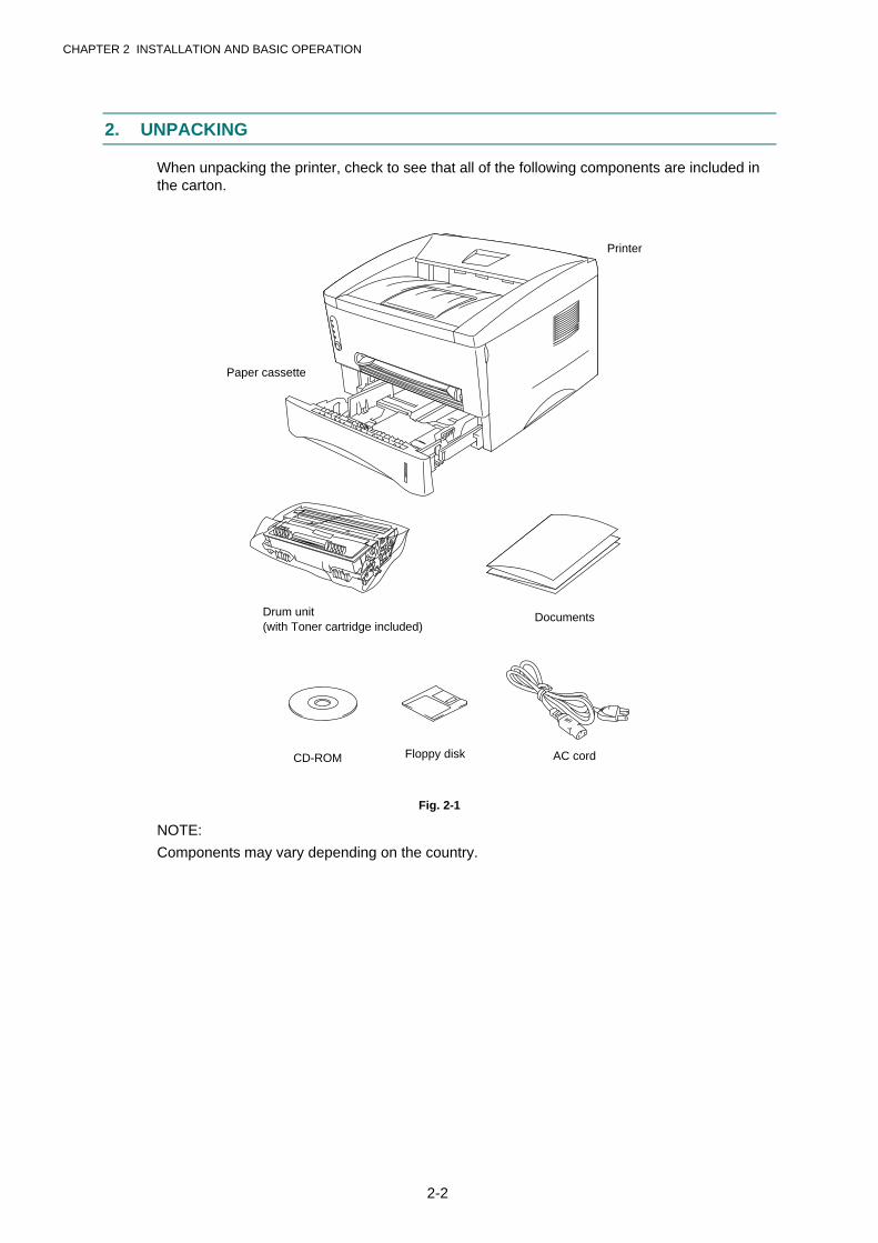
2. UNPACKING
When unpacking the printer, check to see that all of the following components are included inthe carton.
Fig. 2-1
NOTE:
Components may vary depending on the country.
AC cord
Printer
Paper cassette
Drum unit(with Toner cartridge included)
Documents
CD-ROM Floppy disk
CHAPTER 2 INSTALLATION AND BASIC OPERATION
2-3
3. INSTALL THE PRINTER
You need to implement hardware setup and driver installation to use the printer.
Firstly, identify the Operating System on your computer. Then, purchase the appropriateinterface cable (parallel or USB) for your computer.
The installation programs for the hardware setup and driver installation are contained on thesupplied CD-ROM.
If you do not have a CD-ROM drive, you can install the printer driver from the supplied floppydisk. (See Subsection 3.2 ‘For Windows® Users with No CD-ROM Drive’.)
3.1 For Windows® Users
(1) Turn on your PC power. Close all the applications running on your PC.
(2) Insert the supplied CD-ROM into the CD-ROM drive.
(3) The opening screen will appear automatically in Windows� 95/98/NT4.0.
NOTE:
If the opening screen does not appear;
Click Start and select Run. Then, type D:\START in the command line box and click OK. (Ifyour CD-ROM drive is not D, type the correct drive letter instead of “D”.)
In Windows� 3.1;
Click the File menu in the Program Manager screen and select Run. Then, type D:\START inthe command line box and click OK. (If your CD-ROM drive is not D, type the correct driveletter instead of “D”.)
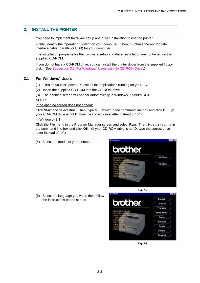
(4) Select the model of your printer.
Fig. 2-2
(5) Select the language you want, then followthe instructions on the screen.
Fig. 2-3

CHAPTER 2 INSTALLATION AND BASIC OPERATION
2-4
(6) Click the Initial Setup button.
Fig. 2-4
(7) You can view the Initial Setup operationsin the video movie.
Fig. 2-5
(8) Click the interface cable you are going touse, Parallel or USB.
Fig. 2-6
(9) If you click the NOW button, you caninstall the printer driver immediately.
(10) After the printer driver has been installed,the HL-1240 or HL-1250 window willappear. Follow the on-screen messagesto complete the installation.
Fig. 2-7
If your printer is connected using a parallel interface cable, the setup is now completed. If youwant to connect your printer using a USB interface cable, refer to Subsection 3.3 ‘Using theUSB Interface (For Windows� 98 only)’.
CHAPTER 2 INSTALLATION AND BASIC OPERATION
2-5
3.2 For Windows® Users with No CD-ROM Drive
If you do not have a CD-ROM drive, setup the printer following the steps below, then install theprinter driver from the floppy disk.
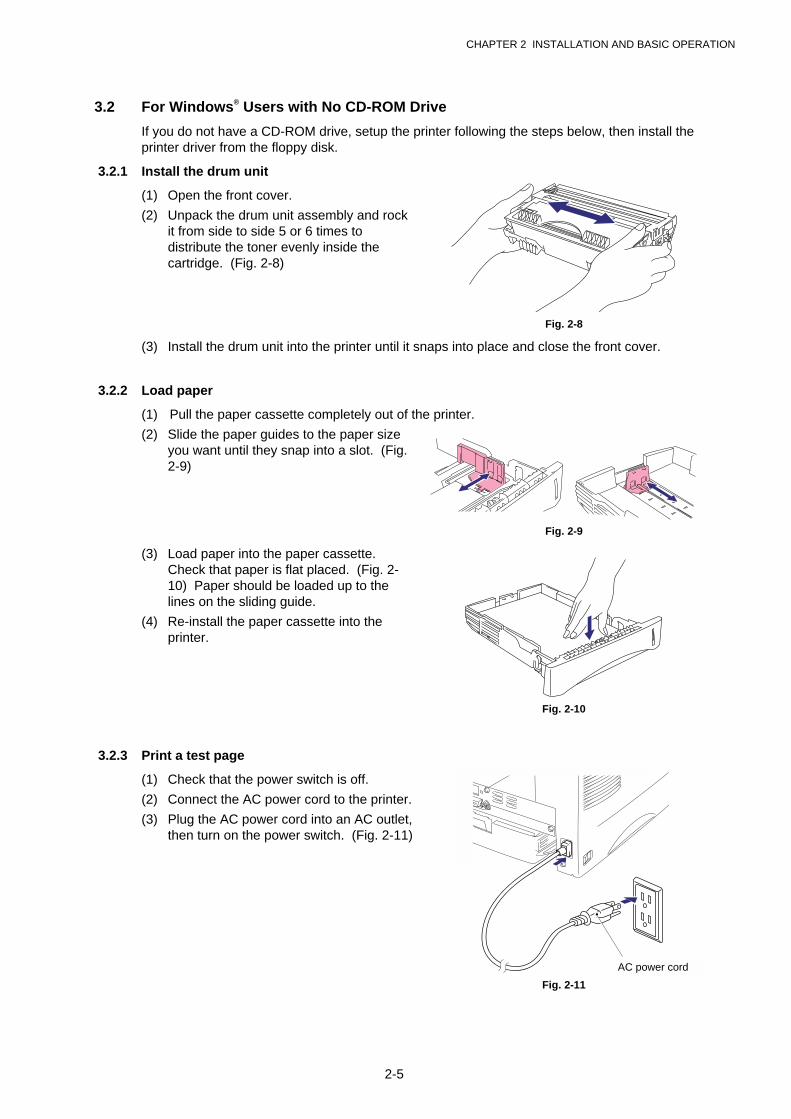
3.2.1 Install the drum unit
(1) Open the front cover.
(2) Unpack the drum unit assembly and rockit from side to side 5 or 6 times todistribute the toner evenly inside thecartridge. (Fig. 2-8)
Fig. 2-8
(3) Install the drum unit into the printer until it snaps into place and close the front cover.
3.2.2 Load paper
(1) Pull the paper cassette completely out of the printer.
(2) Slide the paper guides to the paper sizeyou want until they snap into a slot. (Fig.2-9)
Fig. 2-9
(3) Load paper into the paper cassette.Check that paper is flat placed. (Fig. 2-10) Paper should be loaded up to thelines on the sliding guide.
(4) Re-install the paper cassette into theprinter.
Fig. 2-10
3.2.3 Print a test page
(1) Check that the power switch is off.
(2) Connect the AC power cord to the printer.
(3) Plug the AC power cord into an AC outlet,then turn on the power switch. (Fig. 2-11)
Fig. 2-11
AC power cord

CHAPTER 2 INSTALLATION AND BASIC OPERATION
2-6
(4) Extend the tray extension flap. After theprinter has warmed up the Ready LEDchanges from blinking to lit. (Fig. 2-12)
(5) Press the control panel button. Theprinter will print a test page. Check thetest page printed correctly.
Fig. 2-12
3.2.4 Connect the printer and the computer
(1) Turn off the power switch.
(2) Connect the parallel interface to thecomputer, then connect it to the printer.(Fig. 2-13)
(3) Use the clips on the printer connector tosecure the parallel interface cable.
(4) Turn on the printer power switch.
Fig. 2-13
3.2.5 Install the printer driver from floppy disk
(1) Turn on the computer power. If the “Add New Hardware Wizard” window appears, clickthe Cancel button.
(2) Insert the supplied floppy disk into the floppy disk drive.
(3) Install the printer driver using the Setup.exe file.
In Windows� 95/98
i) Click the Start button and select Run.
ii) Type A:\SETUP and click OK. (If your floppy disk drive is not A, insert the correct driveletter instead of ‘A’.)
iii) Follow the instructions that appear on the screen.
In Windows� 3.1
i) Click File menu in the Program Manager screen and select Run.
ii) Type A:\SETUP click OK. (If your floppy disk drive is not A, insert the correct drive letterinstead of ‘A’.)
iii) Follow the instructions that appear on the screen.
Parallel interfacecable
CHAPTER 2 INSTALLATION AND BASIC OPERATION
2-7
3.3 Using the USB Interface (For Windows� 98 only)
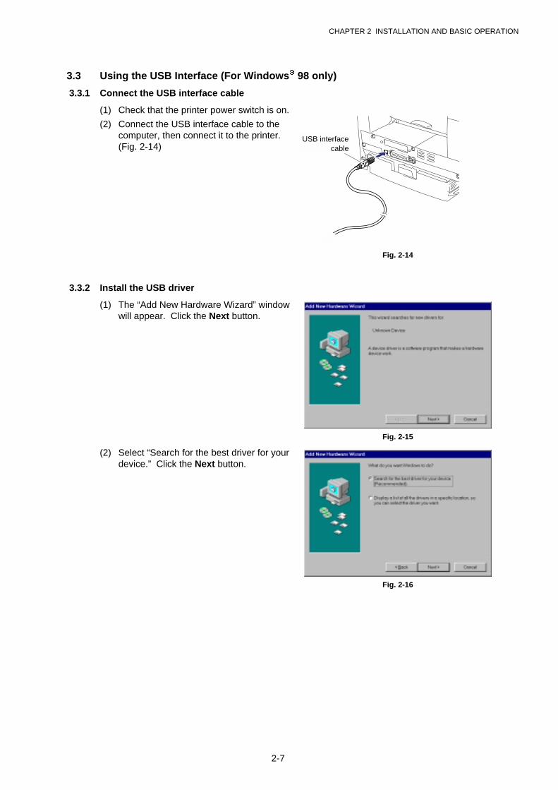
3.3.1 Connect the USB interface cable
(1) Check that the printer power switch is on.
(2) Connect the USB interface cable to thecomputer, then connect it to the printer.(Fig. 2-14)
Fig. 2-14
3.3.2 Install the USB driver
(1) The “Add New Hardware Wizard” windowwill appear. Click the Next button.
Fig. 2-15
(2) Select “Search for the best driver for yourdevice.” Click the Next button.
Fig. 2-16
USB interfacecable
CHAPTER 2 INSTALLATION AND BASIC OPERATION
2-8
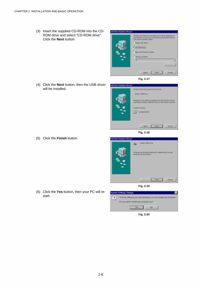
(3) Insert the supplied CD-ROM into the CD-ROM drive and select “CD-ROM drive”.Click the Next button.
Fig. 2-17
(4) Click the Next button, then the USB driverwill be installed.
Fig. 2-18
(5) Click the Finish button.
Fig. 2-19
(6) Click the Yes button, then your PC will re-start.
Fig. 2-20
CHAPTER 2 INSTALLATION AND BASIC OPERATION
2-9
3.3.3 Set the PC printer port
Your PC printer port has to be set to “USB port”.
(1) Click the Start button and select Printers in Settings.
(2) Select your printer model icon in Printers so that the printer icon is highlighted.
(3) Select Properties from the File menu, then click the Details tab.
(4) Select BRUSB: (USB Printer Port) in the“Print to the following port” box. (Fig. 2-21)
(5) Click the OK button to close theProperties dialog box. The setup is nowcompleted.
Fig. 2-21
NOTE:
Both the parallel cable and USB interface cable can be connected to the printer at the sametime.
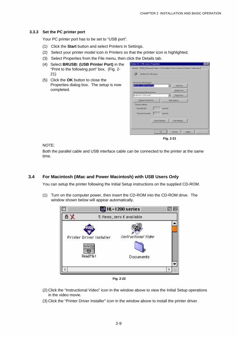
3.4 For Macintosh (iMac and Power Macintosh) with USB Users Only
You can setup the printer following the Initial Setup instructions on the supplied CD-ROM.
(1) Turn on the computer power, then insert the CD-ROM into the CD-ROM drive. Thewindow shown below will appear automatically.
Fig. 2-22
(2) Click the “Instructional Video” icon in the window above to view the Initial Setup operationsin the video movie.
(3) Click the “Printer Driver Installer” icon in the window above to install the printer driver.

CHAPTER 2 INSTALLATION AND BASIC OPERATION
2-10
4. PAPER HANDLING
The printer provides two types of paper loading method; paper cassette and manual feed slot.
4.1 Load Paper into the Paper Cassette
You can load normal paper and transparencies into the paper cassette. If you load paper intothe paper cassette, the printer automatically feeds paper sheet by sheet and ejects the printedpage into the output tray.
For the details on cassette loading, refer to Subsection 3.2.2 ‘Load Paper’ in this chapter andSubsection 3.4 ‘Paper’ in CHAPTER 1.
4.2 Load Paper Manually
You can feed envelopes, labels and organizers as well as normal paper and transparenciesinto the manual feed slot. (For details on feedable paper, see Subsection 3.4 ‘Paper’ inCHAPTER 1.)
When using the manual feed slot, follow the steps below;
(1) Select the manual feed mode in the printer driver, and send the print data to the printer.
NOTE:
A ‘NO PAPER’ message is shown in the status monitor until a sheet of paper is inserted intothe manual feed slot.
(2) Set the width of the manual feed slot paperguides using both hands to the paper width to beused. (Fig. 2-23)
Fig. 2-23
(3) Insert the paper into the manual feed slot withboth hands until the front edge of the papertouches the paper feed roller.
(4) Hold the paper in this position until the printerfeeds the paper a short distance, then let go ofthe paper. (Fig. 2-24)
Fig. 2-24
(5) After the printer ejects the printed page, insert the next sheet of paper as in the previousstep. The printer will wait until you insert the next sheet of paper. Repeat this as necessaryfor the number of pages you need to print.
NOTE:
It is recommended to remove printed pages immediately after printing if the output trayextension flap is not extended.
CHAPTER 2 INSTALLATION AND BASIC OPERATION
2-11
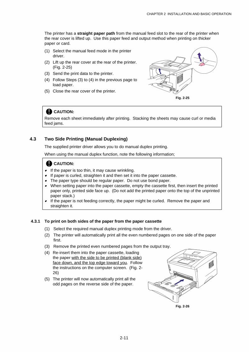
The printer has a straight paper path from the manual feed slot to the rear of the printer whenthe rear cover is lifted up. Use this paper feed and output method when printing on thickerpaper or card.
(1) Select the manual feed mode in the printerdriver.
(2) Lift up the rear cover at the rear of the printer.(Fig. 2-25)
(3) Send the print data to the printer.
(4) Follow Steps (3) to (4) in the previous page toload paper.
(5) Close the rear cover of the printer.
Fig. 2-25
! CAUTION:
Remove each sheet immediately after printing. Stacking the sheets may cause curl or mediafeed jams.
4.3 Two Side Printing (Manual Duplexing)
The supplied printer driver allows you to do manual duplex printing.
When using the manual duplex function, note the following information;
! CAUTION:
� If the paper is too thin, it may cause wrinkling.� If paper is curled, straighten it and then set it into the paper cassette.� The paper type should be regular paper. Do not use bond paper.� When setting paper into the paper cassette, empty the cassette first, then insert the printed
paper only, printed side face up. (Do not add the printed paper onto the top of the unprintedpaper stack.)
� If the paper is not feeding correctly, the paper might be curled. Remove the paper andstraighten it.
4.3.1 To print on both sides of the paper from the paper cassette
(1) Select the required manual duplex printing mode from the driver.
(2) The printer will automatically print all the even numbered pages on one side of the paperfirst.
(3) Remove the printed even numbered pages from the output tray.
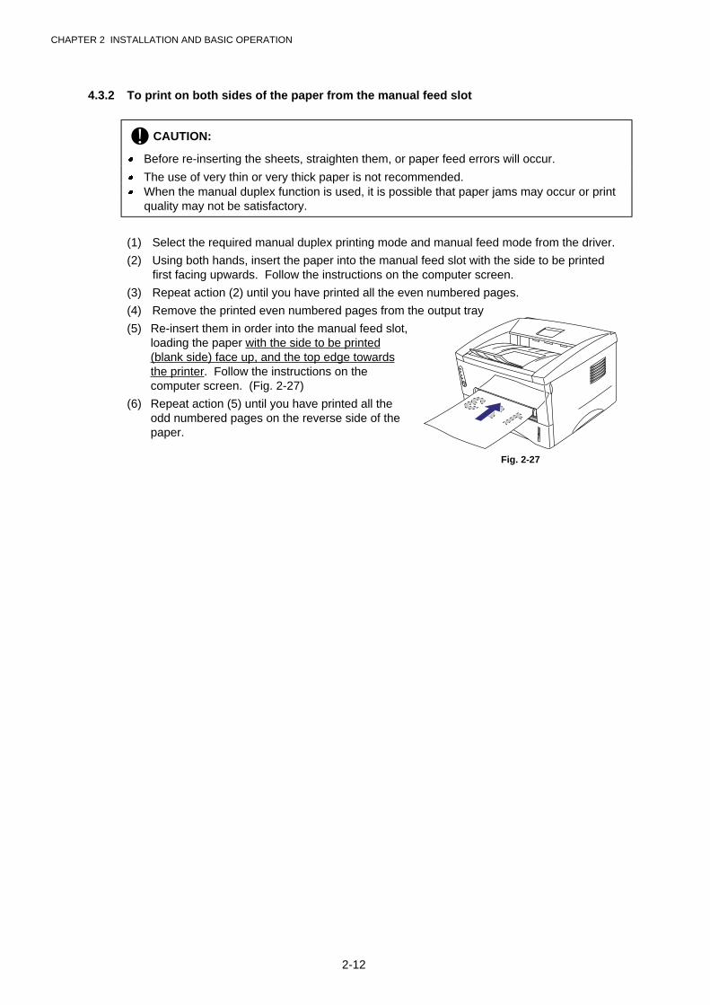
(4) Re-insert them into the paper cassette, loadingthe paper with the side to be printed (blank side)face down, and the top edge toward you. Followthe instructions on the computer screen. (Fig. 2-26)
(5) The printer will now automatically print all theodd pages on the reverse side of the paper.
Fig. 2-26
CHAPTER 2 INSTALLATION AND BASIC OPERATION
2-12
4.3.2 To print on both sides of the paper from the manual feed slot
! CAUTION:
� Before re-inserting the sheets, straighten them, or paper feed errors will occur.
� The use of very thin or very thick paper is not recommended.� When the manual duplex function is used, it is possible that paper jams may occur or print
quality may not be satisfactory.
(1) Select the required manual duplex printing mode and manual feed mode from the driver.
(2) Using both hands, insert the paper into the manual feed slot with the side to be printedfirst facing upwards. Follow the instructions on the computer screen.
(3) Repeat action (2) until you have printed all the even numbered pages.
(4) Remove the printed even numbered pages from the output tray
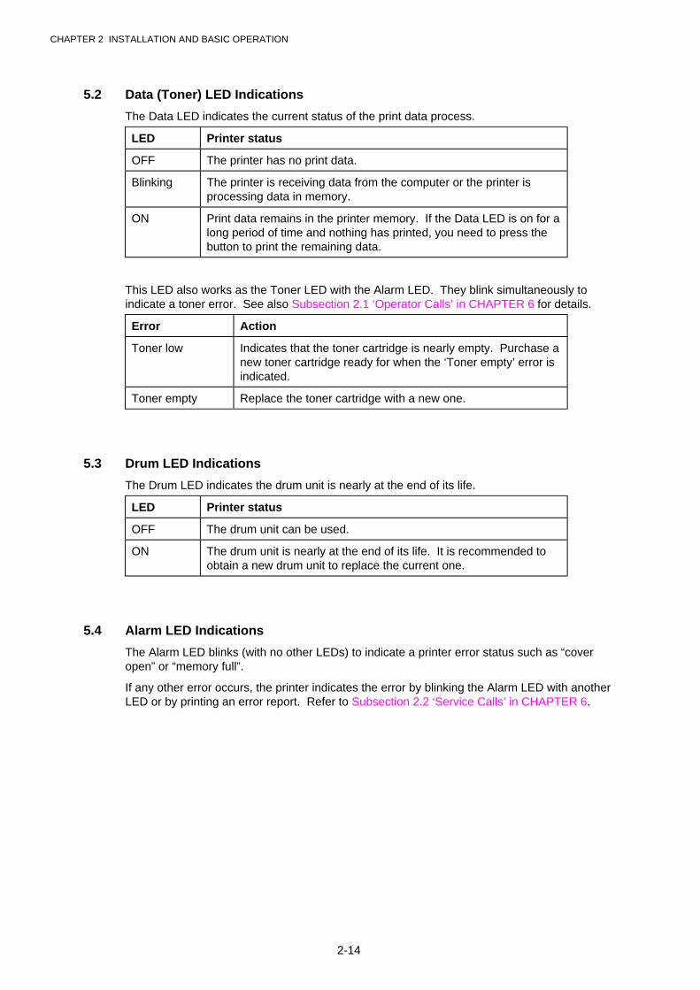
(5) Re-insert them in order into the manual feed slot,loading the paper with the side to be printed(blank side) face up, and the top edge towardsthe printer. Follow the instructions on thecomputer screen. (Fig. 2-27)
(6) Repeat action (5) until you have printed all theodd numbered pages on the reverse side of thepaper.
Fig. 2-27
CHAPTER 2 INSTALLATION AND BASIC OPERATION
2-13
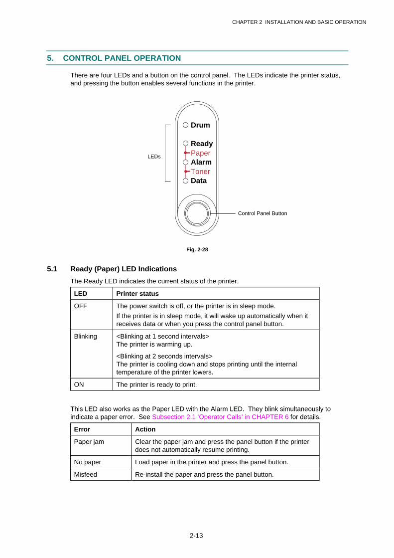
5. CONTROL PANEL OPERATION
There are four LEDs and a button on the control panel. The LEDs indicate the printer status,and pressing the button enables several functions in the printer.
Drum
Ready
AlarmPaper
TonerData
Fig. 2-28
5.1 Ready (Paper) LED Indications
The Ready LED indicates the current status of the printer.
LED Printer status
OFF The power switch is off, or the printer is in sleep mode.
If the printer is in sleep mode, it will wake up automatically when itreceives data or when you press the control panel button.
Blinking <Blinking at 1 second intervals>The printer is warming up.
<Blinking at 2 seconds intervals>The printer is cooling down and stops printing until the internaltemperature of the printer lowers.
ON The printer is ready to print.
This LED also works as the Paper LED with the Alarm LED. They blink simultaneously toindicate a paper error. See Subsection 2.1 ‘Operator Calls’ in CHAPTER 6 for details.
Error Action
Paper jam Clear the paper jam and press the panel button if the printerdoes not automatically resume printing.
No paper Load paper in the printer and press the panel button.
Misfeed Re-install the paper and press the panel button.
Control Panel Button
LEDs
CHAPTER 2 INSTALLATION AND BASIC OPERATION
2-14
5.2 Data (Toner) LED Indications
The Data LED indicates the current status of the print data process.
LED Printer status
OFF The printer has no print data.
Blinking The printer is receiving data from the computer or the printer isprocessing data in memory.
ON Print data remains in the printer memory. If the Data LED is on for along period of time and nothing has printed, you need to press thebutton to print the remaining data.
This LED also works as the Toner LED with the Alarm LED. They blink simultaneously toindicate a toner error. See also Subsection 2.1 ‘Operator Calls’ in CHAPTER 6 for details.
Error Action
Toner low Indicates that the toner cartridge is nearly empty. Purchase anew toner cartridge ready for when the ‘Toner empty’ error isindicated.
Toner empty Replace the toner cartridge with a new one.
5.3 Drum LED Indications
The Drum LED indicates the drum unit is nearly at the end of its life.
LED Printer status
OFF The drum unit can be used.
ON The drum unit is nearly at the end of its life. It is recommended toobtain a new drum unit to replace the current one.
5.4 Alarm LED Indications
The Alarm LED blinks (with no other LEDs) to indicate a printer error status such as “coveropen” or “memory full”.
If any other error occurs, the printer indicates the error by blinking the Alarm LED with anotherLED or by printing an error report. Refer to Subsection 2.2 ‘Service Calls’ in CHAPTER 6.
CHAPTER 2 INSTALLATION AND BASIC OPERATION
2-15
5.5 Control Panel Button Operations
The control panel button is used for the following purposes depending on the situation.
Operation Description
Cancel printing If the button is pressed during printing, the printer immediately stopsprinting and ejects the paper.
Wake-up If the printer is in sleep mode, pressing the button wakes it up into theready status. It will take up to 45 seconds for the printer to go into theready status.
Form feed If the Data LED is on, press the button. The printer prints any dataremaining in the printer memory.
Error recovery If an error occurs, the printer will recover from some errors automatically.If the error does not clear automatically, press the button to clear the errorand continue printer operation.
Reprint function You can reprint a print job without sending it from the computer again.When you press the button with the Data LED off, the printer reprints thelast job you printed if the whole job can be kept in printer memory. If theprint job is too large or there is insufficient memory, the last page only willbe reprinted.
5.6 Other Control Features
The printer has the following useful features;
5.6.1 Sleep mode
When the printer does not receive data for a certain period of time (timeout), it enters sleepmode. The default timeout is 5 minutes and it is automatically adjusted to the most suitabletime-out setting depending on the frequency of your printer use (Intelligent Sleep Mode).
While the printer is in sleep mode, all the LEDs are off and it is as if it was turned off, but theprinter can still receive data from the computer. Receiving a print file or documentautomatically wakes up the printer to start printing. Pressing the button also wakes up theprinter.
NOTE:
� When the printer goes into sleep mode, the fan will not stop until the printer engine hascooled down. The fan running time varies depending on the sleep mode timeout becausethe fan running conditions are defined as follows;
1) The fan runs for 10 minutes whenever printing finishes.
2) The fan runs while the printer is in ready status.
3) The fan runs for at least 5 minutes after the printer goes into sleep mode.
(EX: If the timeout is 5 minutes, the fan will be running for 5 minutes after the printer goesinto sleep mode.)
� Sleep mode allows the print engine to cool, so the temperature of the room and how longthe printer has been in sleep mode affects the warm-up time. This warm-up time can takeup to 45 seconds. The Ready LED blinks to indicate that the printer is warming up.
� You can change the timeout for the sleep mode with the supplied printer driver (all models)or Remote Printer Console program. The time-out setting is in the range of 1 to 15 minutes.Refer to the Help section in the printer driver or RPC program for more information aboutthe sleep mode setting.

CHAPTER 2 INSTALLATION AND BASIC OPERATION
2-16
5.6.2 Test print mode
The printer incorporates various test print modes. The printer enters into each test print modeby panel button operation.
For details on test print mode, see Subsection 9.1 ‘Test Print Mode’ in CHAPTER 6.
CHAPTER 3 THEORY OF OPERATION
3-1
CHAPTER 3 THEORY OF OPERATION
1. ELECTRONICS
1.1 General Block Diagram
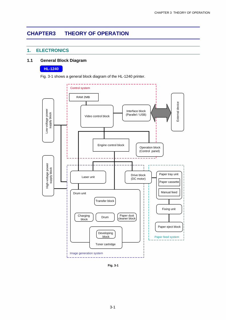
Fig. 3-1 shows a general block diagram of the HL-1240 printer.
Video control block
Interface block(Parallel / USB)
Engine control blockOperation block
(Control panel)
Control system
Low
-vol
tage
pow
er s
uppl
y bl
ock
Hig
h-vo
ltage
pow
er s
uppl
y bl
ock
Laser unitDrive block(DC motor)
Drum unit
Transfer block
DrumCharging block
Ext
erna
l dev
ice
Paper tray unit
Paper cassette
Manual feed
Fixing unit
Paper eject block
Paper feed system
Image generation system
RAM 2MB
Paper dustcleaner block
Developing block
Toner cartridge
Fig. 3-1
HL-1240
CHAPTER 3 THEORY OF OPERATION
3-2
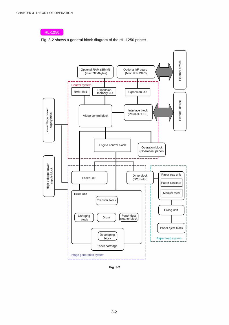
Fig. 3-2 shows a general block diagram of the HL-1250 printer.
Optional RAM (SIMM) (max. 32Mbytes)
Optional I/F board (Mac. RS-232C)
Expansion memory I/O Expansion I/O
Video control block
Engine control blockOperation block
(Operation panel)
Control system
Low
-vol
tage
pow
er s
uppl
y bl
ock
Hig
h-vo
ltage
pow
er s
uppl
y bl
ock
Laser unitDrive block(DC motor)
Drum unit
Transfer block
DrumCharging block
Ext
erna
l dev
ice
Ext
erna
l dev
ice
Paper tray unit
Paper cassette
Manual feed
Fixing unit
Paper eject block
Paper feed system
Image generation system
Interface block(Parallel / USB)
RAM 4MB
Paper dustcleaner block
Developing block
Toner cartridge
Fig. 3-2
HL-1250
CHAPTER 3 THEORY OF OPERATION
3-3
1.2 Main PCB Block Diagram
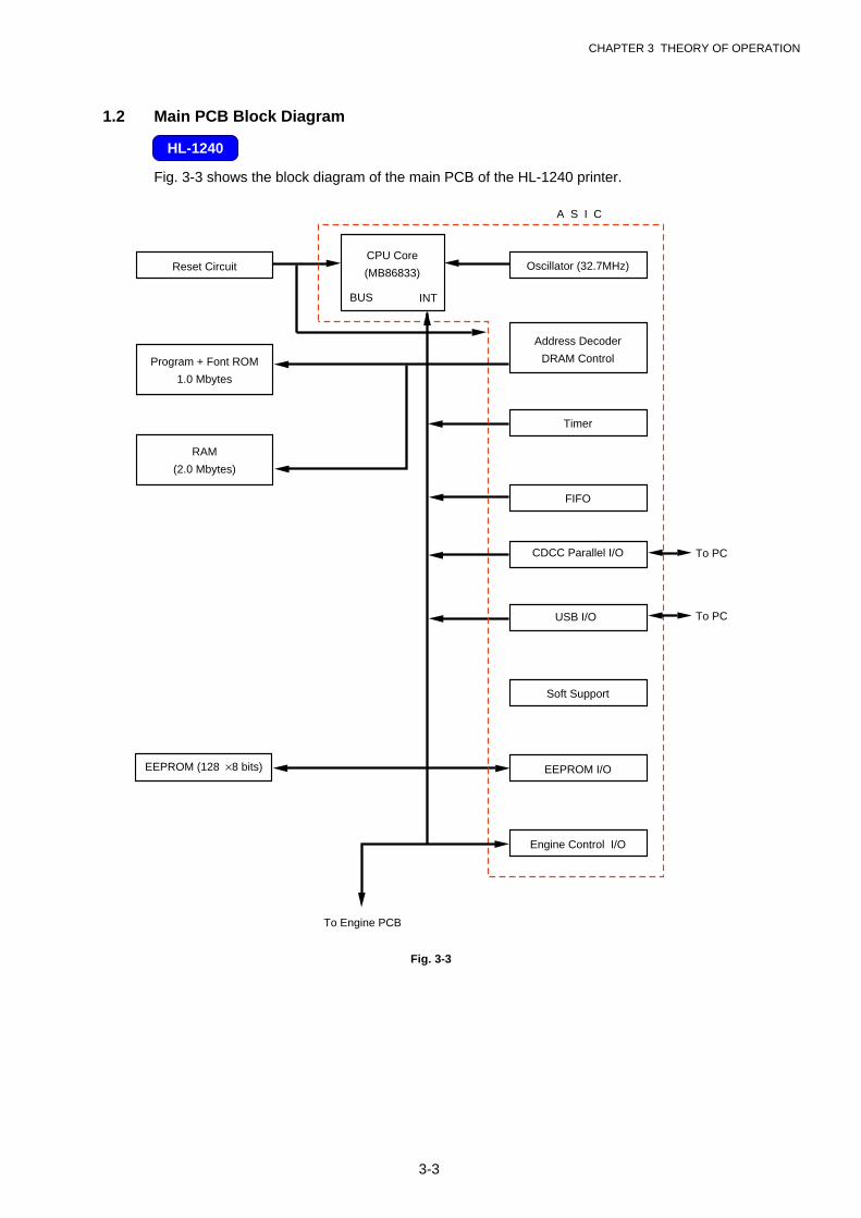
Fig. 3-3 shows the block diagram of the main PCB of the HL-1240 printer.
Reset Circuit
Program + Font ROM
1.0 Mbytes
RAM
(2.0 Mbytes)
EEPROM (128 8 bits)
A S I C
Oscillator (32.7MHz)
Address Decoder
DRAM Control
Timer
FIFO
CDCC Parallel I/O
Soft Support
EEPROM I/O
Engine Control I/O
To Engine PCB
CPU Core
(MB86833)
BUS INT
To PCUSB I/O
To PC
Fig. 3-3
HL-1240
CHAPTER 3 THEORY OF OPERATION
3-4
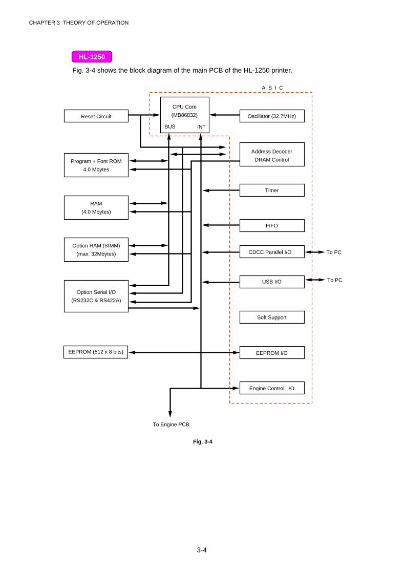
Fig. 3-4 shows the block diagram of the main PCB of the HL-1250 printer.
Reset Circuit
Program + Font ROM
4.0 Mbytes
RAM
(4.0 Mbytes)
Option RAM (SIMM)
(max. 32Mbytes)
Option Serial I/O
(RS232C & RS422A)
EEPROM (512 x 8 bits)
CPU Core
(MB86832)
A S I C
Oscillator (32.7MHz)
Address Decoder
DRAM Control
Timer
FIFO
CDCC Parallel I/O
Soft Support
EEPROM I/O
Engine Control I/O
To Engine PCB
BUS INT
To PCUSB I/O
To PC
Fig. 3-4
HL-1250
CHAPTER 3 THEORY OF OPERATION
3-5
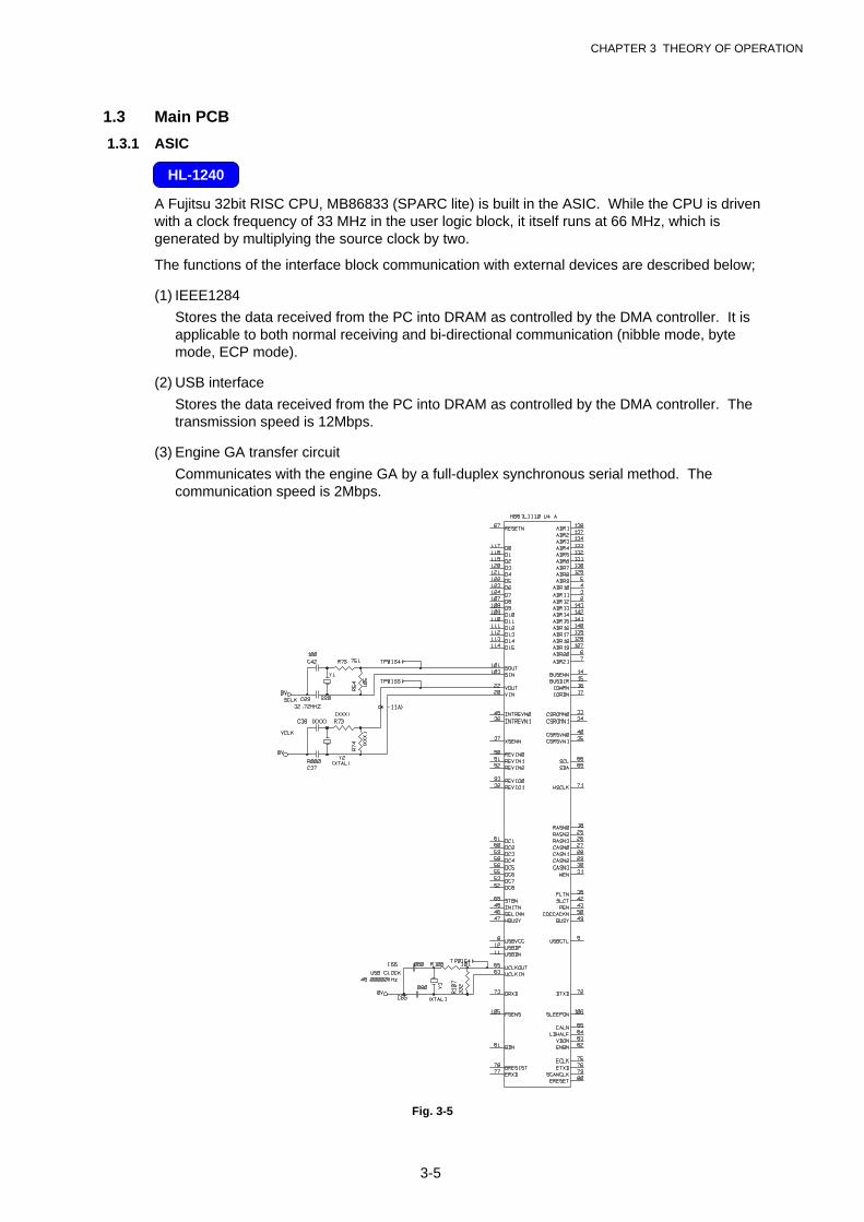
1.3 Main PCB
1.3.1 ASIC
A Fujitsu 32bit RISC CPU, MB86833 (SPARC lite) is built in the ASIC. While the CPU is drivenwith a clock frequency of 33 MHz in the user logic block, it itself runs at 66 MHz, which isgenerated by multiplying the source clock by two.
The functions of the interface block communication with external devices are described below;
(1) IEEE1284
Stores the data received from the PC into DRAM as controlled by the DMA controller. It isapplicable to both normal receiving and bi-directional communication (nibble mode, bytemode, ECP mode).
(2) USB interface
Stores the data received from the PC into DRAM as controlled by the DMA controller. Thetransmission speed is 12Mbps.
(3) Engine GA transfer circuit
Communicates with the engine GA by a full-duplex synchronous serial method. Thecommunication speed is 2Mbps.
Fig. 3-5
HL-1240

CHAPTER 3 THEORY OF OPERATION
3-6
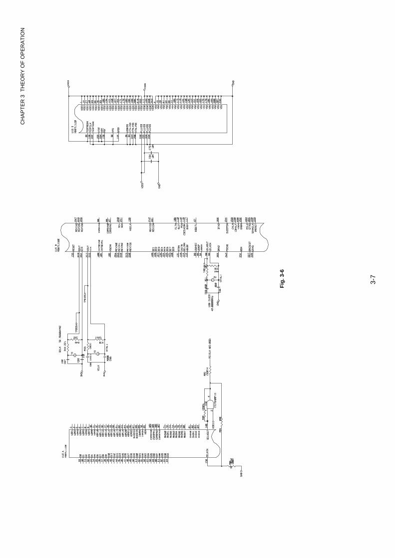
A Fujitsu 32bit RISC CPU, MB86832 (SPARC lite) is built in the ASIC. While the CPU is drivenwith a clock frequency of 33 MHz in the user logic block, it itself runs at 66 MHz, which isgenerated by multiplying the source clock by two.
The functions of the interface block communication with external devices are described below;
(1) IEEE1284
Stores the data received from the PC into DRAM as controlled by the DMA controller. It isapplicable to both normal receiving and bi-directional communication (nibble mode, bytemode, ECP mode).
(2) USB interface
Stores the data received from the PC into DRAM as controlled by the DMA controller. Thetransmission speed is 12Mbps.
(3) Engine GA transfer circuit
Communicates with the engine GA by a full-duplex synchronous serial method. Thecommunication speed is 2Mbps.
HL-1250
CH
AP
TE
R 3
TH
EO
RY
OF
OP
ER
AT
ION
3-7
Fig
. 3-6
CHAPTER 3 THEORY OF OPERATION
3-8
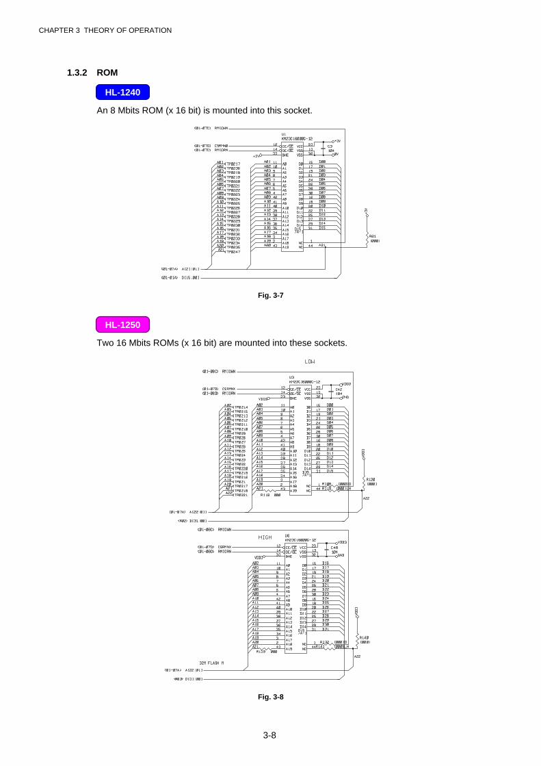
1.3.2 ROM
An 8 Mbits ROM (x 16 bit) is mounted into this socket.
Fig. 3-7
Two 16 Mbits ROMs (x 16 bit) are mounted into these sockets.
Fig. 3-8
HL-1240
HL-1250
CHAPTER 3 THEORY OF OPERATION
3-9
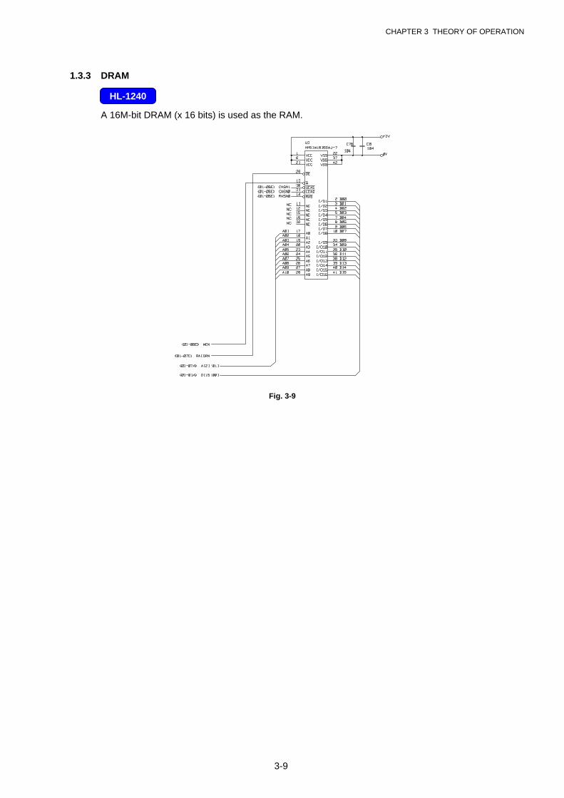
1.3.3 DRAM
A 16M-bit DRAM (x 16 bits) is used as the RAM.
Fig. 3-9
HL-1240
CHAPTER 3 THEORY OF OPERATION
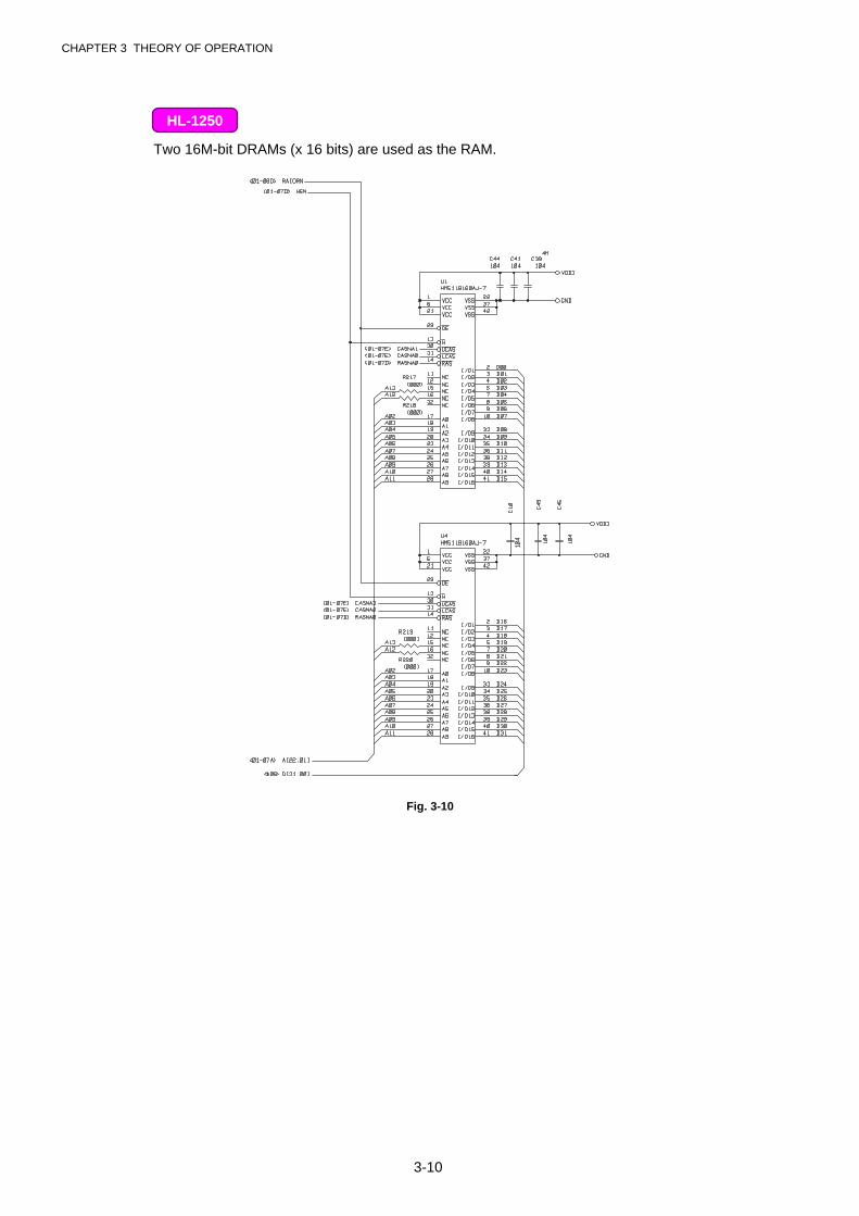
3-10
Two 16M-bit DRAMs (x 16 bits) are used as the RAM.
Fig. 3-10
HL-1250
CHAPTER 3 THEORY OF OPERATION
3-11
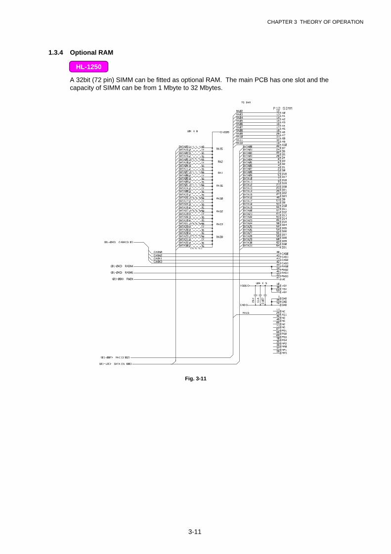
1.3.4 Optional RAM
A 32bit (72 pin) SIMM can be fitted as optional RAM. The main PCB has one slot and thecapacity of SIMM can be from 1 Mbyte to 32 Mbytes.
Fig. 3-11
HL-1250
CHAPTER 3 THEORY OF OPERATION
3-12
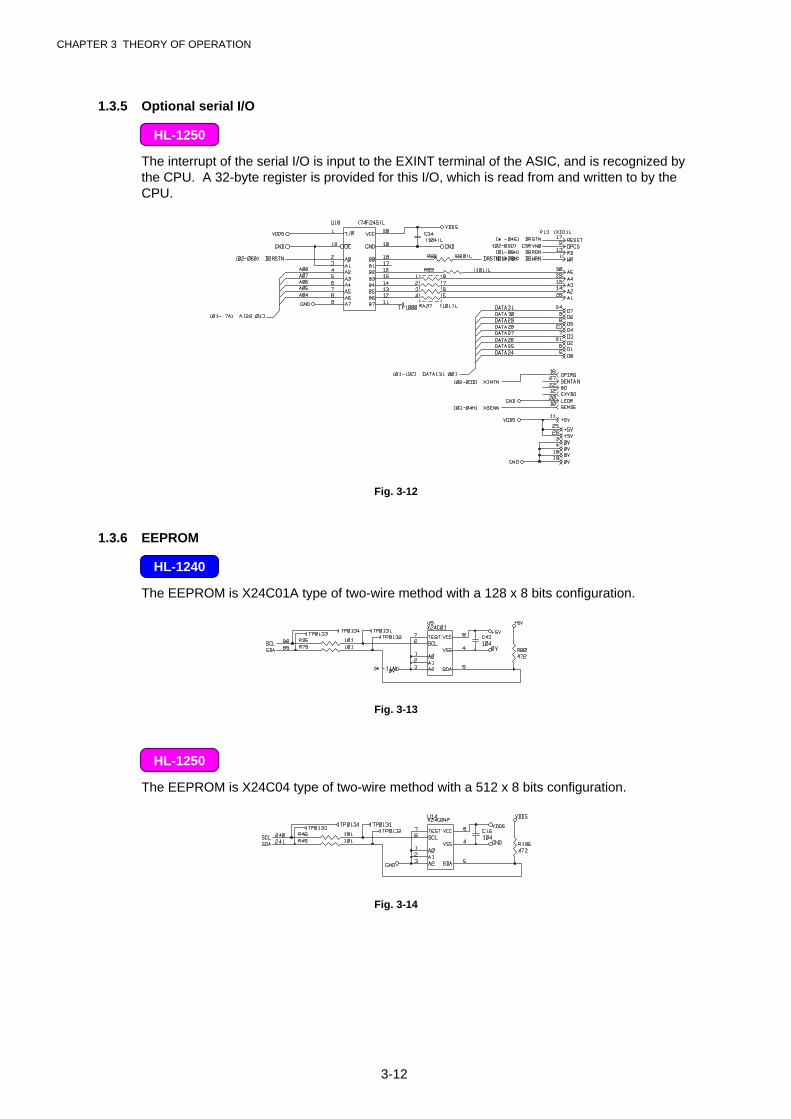
1.3.5 Optional serial I/O
The interrupt of the serial I/O is input to the EXINT terminal of the ASIC, and is recognized bythe CPU. A 32-byte register is provided for this I/O, which is read from and written to by theCPU.
Fig. 3-12
1.3.6 EEPROM
The EEPROM is X24C01A type of two-wire method with a 128 x 8 bits configuration.
Fig. 3-13
The EEPROM is X24C04 type of two-wire method with a 512 x 8 bits configuration.
Fig. 3-14
HL-1250
HL-1240
HL-1250
CHAPTER 3 THEORY OF OPERATION
3-13
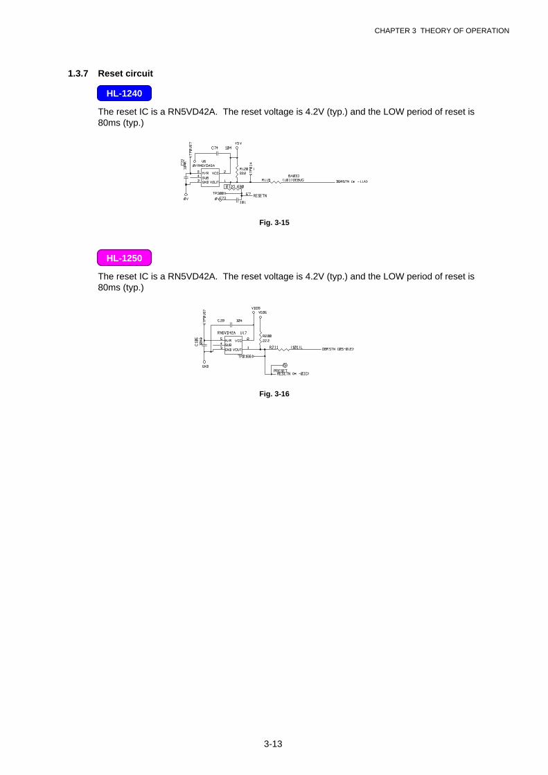
1.3.7 Reset circuit
The reset IC is a RN5VD42A. The reset voltage is 4.2V (typ.) and the LOW period of reset is80ms (typ.)
Fig. 3-15
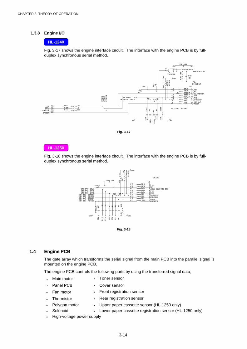
The reset IC is a RN5VD42A. The reset voltage is 4.2V (typ.) and the LOW period of reset is80ms (typ.)
Fig. 3-16
HL-1240
HL-1250
CHAPTER 3 THEORY OF OPERATION
3-14
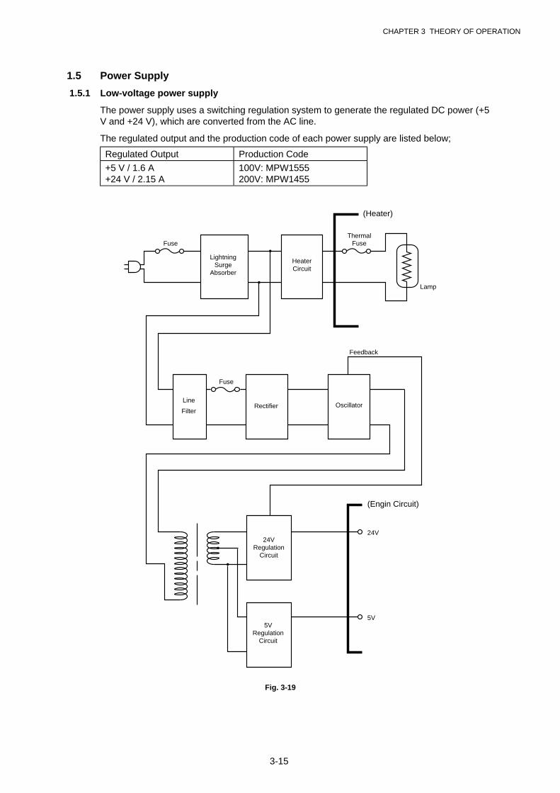
1.3.8 Engine I/O
Fig. 3-17 shows the engine interface circuit. The interface with the engine PCB is by full-duplex synchronous serial method.
Fig. 3-17
Fig. 3-18 shows the engine interface circuit. The interface with the engine PCB is by full-duplex synchronous serial method.
Fig. 3-18
1.4 Engine PCB
The gate array which transforms the serial signal from the main PCB into the parallel signal ismounted on the engine PCB.
The engine PCB controls the following parts by using the transferred signal data;
� Main motor � Toner sensor
� Panel PCB � Cover sensor
� Fan motor � Front registration sensor
� Thermistor � Rear registration sensor
� Polygon motor � Upper paper cassette sensor (HL-1250 only)� Solenoid � Lower paper cassette registration sensor (HL-1250 only)� High-voltage power supply
HL-1240
HL-1250
CHAPTER 3 THEORY OF OPERATION
3-15
1.5 Power Supply
1.5.1 Low-voltage power supply
The power supply uses a switching regulation system to generate the regulated DC power (+5V and +24 V), which are converted from the AC line.
The regulated output and the production code of each power supply are listed below;
Regulated Output Production Code
+5 V / 1.6 A+24 V / 2.15 A
100V: MPW1555200V: MPW1455
HeaterCircuit
ThermalFuse
LightningSurge
Absorber
Feedback
Line
Filter
Fuse
Rectifier Oscillator
24VRegulation
Circuit
24V
5V
Lamp
(Heater)
(Engin Circuit)
Fuse
5VRegulation
Circuit
Fig. 3-19
CHAPTER 3 THEORY OF OPERATION
3-16
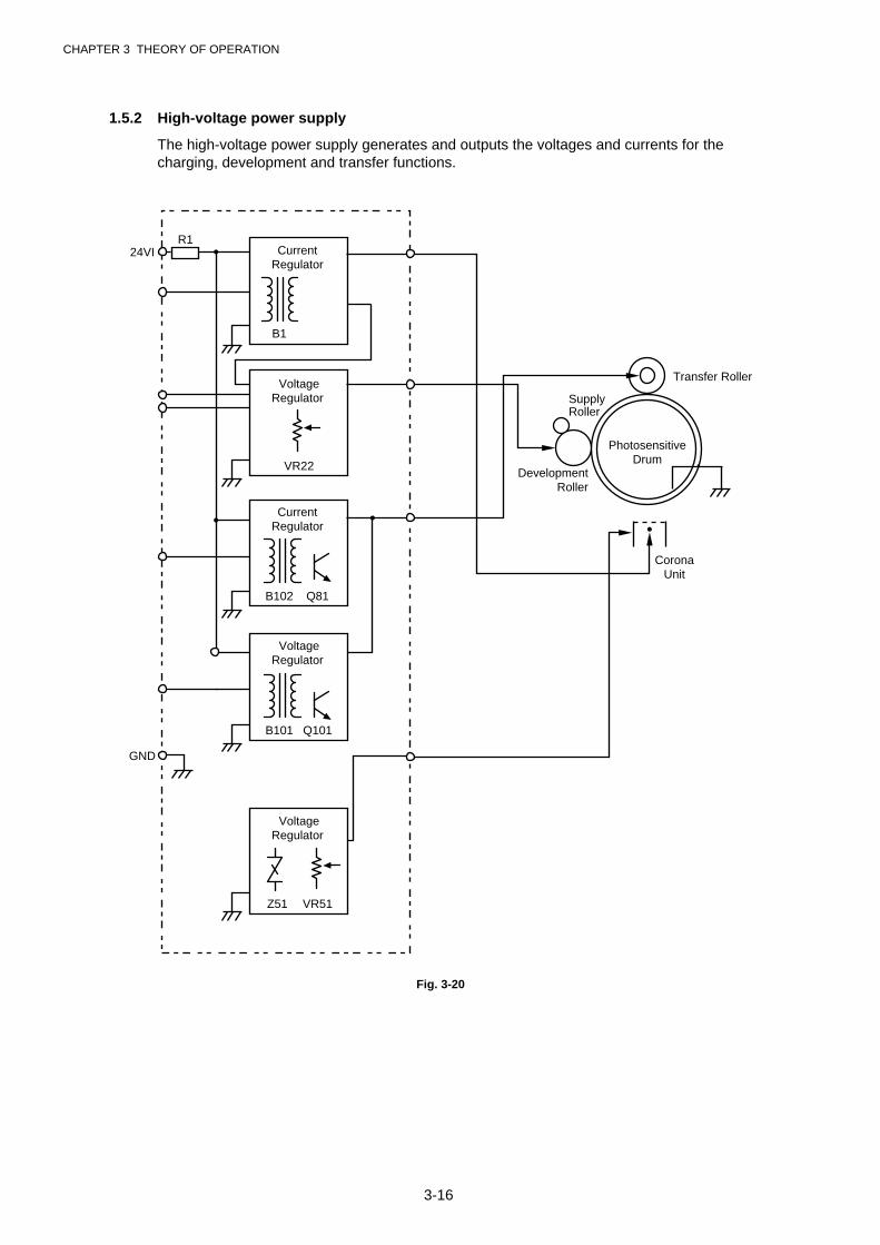
1.5.2 High-voltage power supply
The high-voltage power supply generates and outputs the voltages and currents for thecharging, development and transfer functions.
Transfer Roller
SupplyRoller
PhotosensitiveDrum
DevelopmentRoller
CoronaUnit
CurrentRegulator
CurrentRegulator
VoltageRegulator
VoltageRegulator
B1
B102 Q81
B101 Q101
VoltageRegulator
Z51 VR51
VR22
24VI
GND
R1
Fig. 3-20
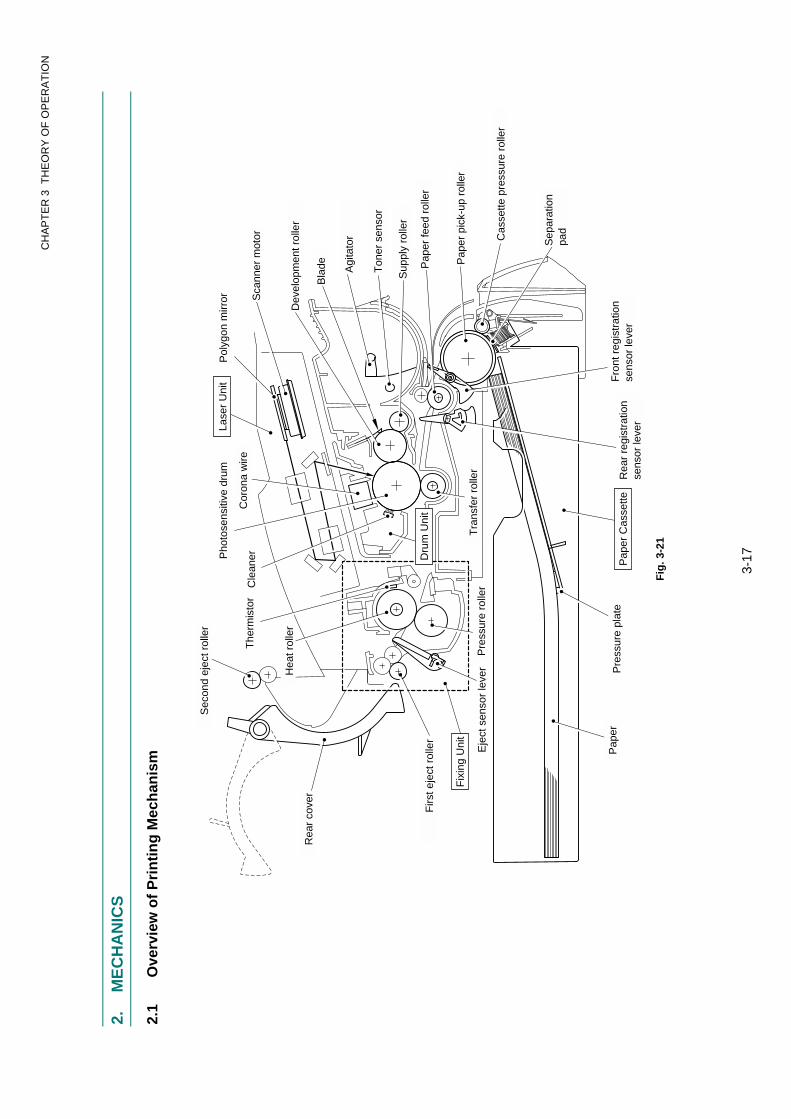
CH
AP
TE
R 3
TH
EO
RY
OF
OP
ER
AT
ION
3-17
2.
ME
CH
AN
ICS
2.1
Ove
rvie
w o
f P
rin
tin
g M
ech
anis
m
Fig
. 3-2
1
Sec
ond
ejec
t rol
ler
Pap
er
Firs
t eje
ct r
olle
r
Rea
r co
ver
Pap
er C
asse
tteP
ress
ure
plat
eR
ear
regi
stra
tion
sens
or le
ver
Sep
arat
ion
pad
Fro
nt r
egis
trat
ion
sens
or le
ver
Cas
sette
pre
ssur
e ro
ller
Pap
er p
ick-
up r
olle
r
Pap
er fe
ed r
olle
r
Sup
ply
rolle
r
Ton
er s
enso
r
Agi
tato
r
Bla
de
Dev
elop
men
t rol
ler
Sca
nner
mot
or
Pol
ygon
mirr
orLa
ser
Uni
t
Cor
ona
wire
Hea
t rol
ler
Cle
anerP
hoto
sens
itive
dru
m
The
rmis
tor
Eje
ct s
enso
r le
ver
Pre
ssur
e ro
ller
Dru
m U
nit
Fix
ing
Uni
tT
rans
fer
rolle
r

CHAPTER 3 THEORY OF OPERATION
3-18
Laser
Main PCB
Engine PCB
Polygon Motor
Laser Unit
Cover Sensor (A)
Main Motor
Solenoid
Fan Motor
Toner Sensor PCB (light emission)
Toner Sensor PCB (light reception)
Thermistor (for Heat Roller)
Panel PCB
Low-VoltagePower Supply
PCB
Fixing Unit
Halogen Heater Lamp
Front Registration Sensor
Rear Registration Sensor
Upper PaperCassette Sensor(HL-1250)
Lower PaperCassette Registration Sensor(HL-1250)
High-VoltagePowerSupplyPCB
Drum Unit
Primary Charger (Corona Wire)
Primary Charger (Grid)
Supply Roller
Transfer Roller
Development Roller
Cover Sensor (B)
Fig. 3-22
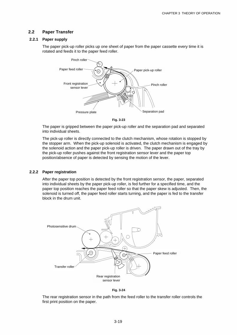
CHAPTER 3 THEORY OF OPERATION
3-19
2.2 Paper Transfer
2.2.1 Paper supply
The paper pick-up roller picks up one sheet of paper from the paper cassette every time it isrotated and feeds it to the paper feed roller.
Fig. 3-23
The paper is gripped between the paper pick-up roller and the separation pad and separatedinto individual sheets.
The pick-up roller is directly connected to the clutch mechanism, whose rotation is stopped bythe stopper arm. When the pick-up solenoid is activated, the clutch mechanism is engaged bythe solenoid action and the paper pick-up roller is driven. The paper drawn out of the tray bythe pick-up roller pushes against the front registration sensor lever and the paper topposition/absence of paper is detected by sensing the motion of the lever.
2.2.2 Paper registration
After the paper top position is detected by the front registration sensor, the paper, separatedinto individual sheets by the paper pick-up roller, is fed further for a specified time, and thepaper top position reaches the paper feed roller so that the paper skew is adjusted. Then, thesolenoid is turned off, the paper feed roller starts turning, and the paper is fed to the transferblock in the drum unit.
Fig. 3-24
The rear registration sensor in the path from the feed roller to the transfer roller controls thefirst print position on the paper.
Pinch roller
Paper pick-up roller
Front registrationsensor lever
Paper feed roller
Pinch roller
Separation padPressure plate
Photosensitive drum
Transfer roller
Paper feed roller
Rear registrationsensor lever
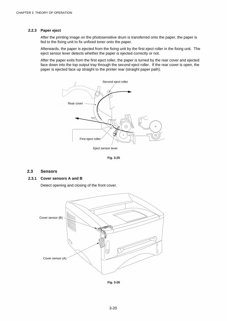
CHAPTER 3 THEORY OF OPERATION
3-20
2.2.3 Paper eject
After the printing image on the photosensitive drum is transferred onto the paper, the paper isfed to the fixing unit to fix unfixed toner onto the paper.
Afterwards, the paper is ejected from the fixing unit by the first eject roller in the fixing unit. Theeject sensor lever detects whether the paper is ejected correctly or not.
After the paper exits from the first eject roller, the paper is turned by the rear cover and ejectedface down into the top output tray through the second eject roller. If the rear cover is open, thepaper is ejected face up straight to the printer rear (straight paper path).
Fig. 3-25
2.3 Sensors
2.3.1 Cover sensors A and B
Detect opening and closing of the front cover.
Fig. 3-26
Second eject roller
First eject roller
Rear cover
Eject sensor lever
Cover sensor (A)
Cover sensor (B)
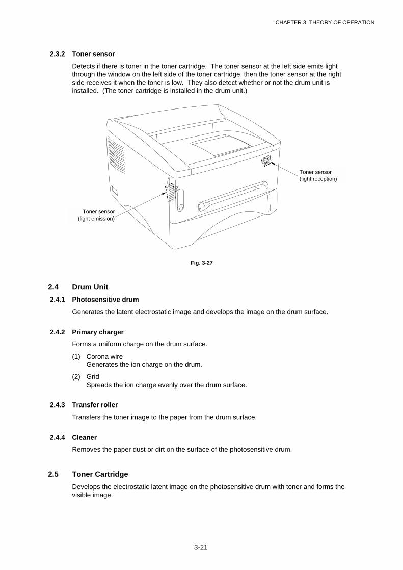
CHAPTER 3 THEORY OF OPERATION
3-21
2.3.2 Toner sensor
Detects if there is toner in the toner cartridge. The toner sensor at the left side emits lightthrough the window on the left side of the toner cartridge, then the toner sensor at the rightside receives it when the toner is low. They also detect whether or not the drum unit isinstalled. (The toner cartridge is installed in the drum unit.)
Fig. 3-27
2.4 Drum Unit
2.4.1 Photosensitive drum
Generates the latent electrostatic image and develops the image on the drum surface.
2.4.2 Primary charger
Forms a uniform charge on the drum surface.
(1) Corona wire Generates the ion charge on the drum.
(2) GridSpreads the ion charge evenly over the drum surface.
2.4.3 Transfer roller
Transfers the toner image to the paper from the drum surface.
2.4.4 Cleaner
Removes the paper dust or dirt on the surface of the photosensitive drum.
2.5 Toner Cartridge
Develops the electrostatic latent image on the photosensitive drum with toner and forms thevisible image.
Toner sensor(light emission)
Toner sensor(light reception)
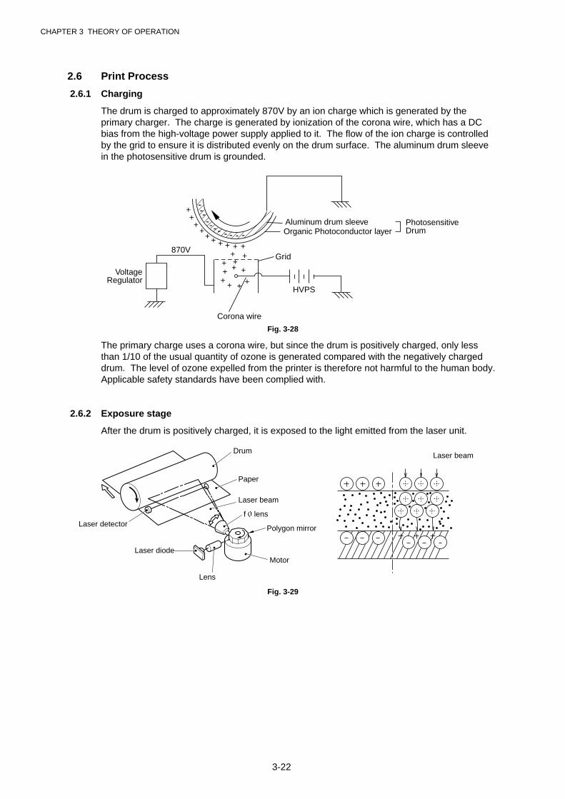
CHAPTER 3 THEORY OF OPERATION
3-22
2.6 Print Process
2.6.1 Charging
The drum is charged to approximately 870V by an ion charge which is generated by theprimary charger. The charge is generated by ionization of the corona wire, which has a DCbias from the high-voltage power supply applied to it. The flow of the ion charge is controlledby the grid to ensure it is distributed evenly on the drum surface. The aluminum drum sleevein the photosensitive drum is grounded.
+++
++ + + + +
++
+++
+++
+ + ++
------- - - - - Organic Photoconductor layer
Aluminum drum sleeve PhotosensitiveDrum
HVPS
870V
VoltageRegulator
Grid
Corona wire
Fig. 3-28
The primary charge uses a corona wire, but since the drum is positively charged, only lessthan 1/10 of the usual quantity of ozone is generated compared with the negatively chargeddrum. The level of ozone expelled from the printer is therefore not harmful to the human body.Applicable safety standards have been complied with.
2.6.2 Exposure stage
After the drum is positively charged, it is exposed to the light emitted from the laser unit.
Fig. 3-29
Drum
Lens
Laser beam
Polygon mirror
Paper
Laser detector
Laser diodeMotor
Laser beam
f � lens

CHAPTER 3 THEORY OF OPERATION
3-23
The area exposed to the laser beam is the image to be printed. The surface potential of theexposed area is reduced, forming the electrostatic image to be printed.
1 Cycle of drumS
urfa
ce P
oten
tial (
V)
+870
+420
+200
1 2 3
(a)
(b)
Time
1
2
3
Primary charging
Laser beam exposure and developing(a) Unexposed area ( Non image area )(b) Exposed area ( Image area )
Transfer the image to paper
DrumSleeve 0
Fig. 3-30
2.6.3 Developing
Developing causes the toner to be attracted to the electrostatic image on the drum so as totransform it into a visible image.
The developer consists of a non-magnetic toner. The development roller is made ofconductive rubber and the supply roller (which is also made of conductive sponge) rotateagainst each other. The toner is charged and carried from the supply roller to the developmentroller. The toner adheres to the development roller and is conveyed to the photosensitive drumat an even thickness controlled by the blade. The toner is nipped between the developmentroller and the drum and developed onto the latent image on the drum. The electrostatic fieldbetween the drum and the development roller, which is DC-biased from the high-voltage powersupply, creates the electrostatic potential to attract toner particles from the development rollerto the latent image area on the drum surface.
Fig. 3-31
Photosensitive drum
Corona wire
Development roller
Blade
Supply rollerTransfer roller
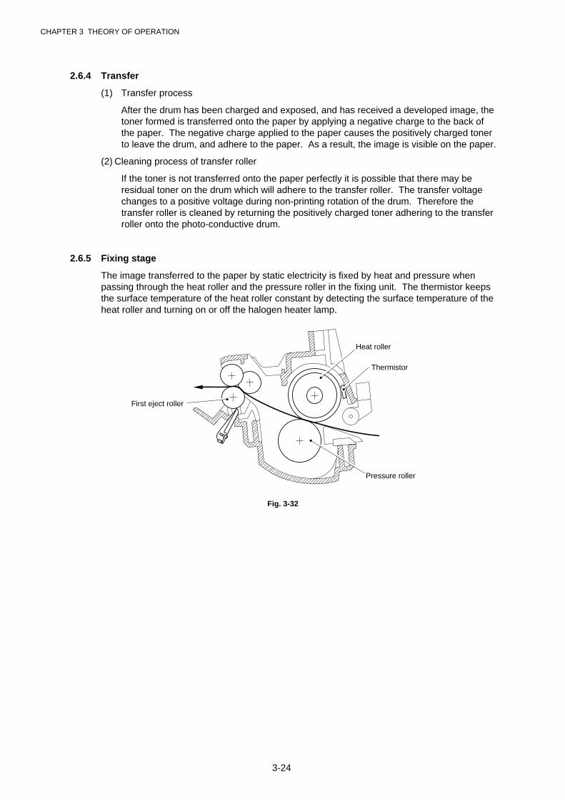
CHAPTER 3 THEORY OF OPERATION
3-24
2.6.4 Transfer
(1) Transfer process
After the drum has been charged and exposed, and has received a developed image, thetoner formed is transferred onto the paper by applying a negative charge to the back ofthe paper. The negative charge applied to the paper causes the positively charged tonerto leave the drum, and adhere to the paper. As a result, the image is visible on the paper.
(2) Cleaning process of transfer roller
If the toner is not transferred onto the paper perfectly it is possible that there may beresidual toner on the drum which will adhere to the transfer roller. The transfer voltagechanges to a positive voltage during non-printing rotation of the drum. Therefore thetransfer roller is cleaned by returning the positively charged toner adhering to the transferroller onto the photo-conductive drum.
2.6.5 Fixing stage
The image transferred to the paper by static electricity is fixed by heat and pressure whenpassing through the heat roller and the pressure roller in the fixing unit. The thermistor keepsthe surface temperature of the heat roller constant by detecting the surface temperature of theheat roller and turning on or off the halogen heater lamp.
Fig. 3-32
First eject roller
Thermistor
Pressure roller
Heat roller
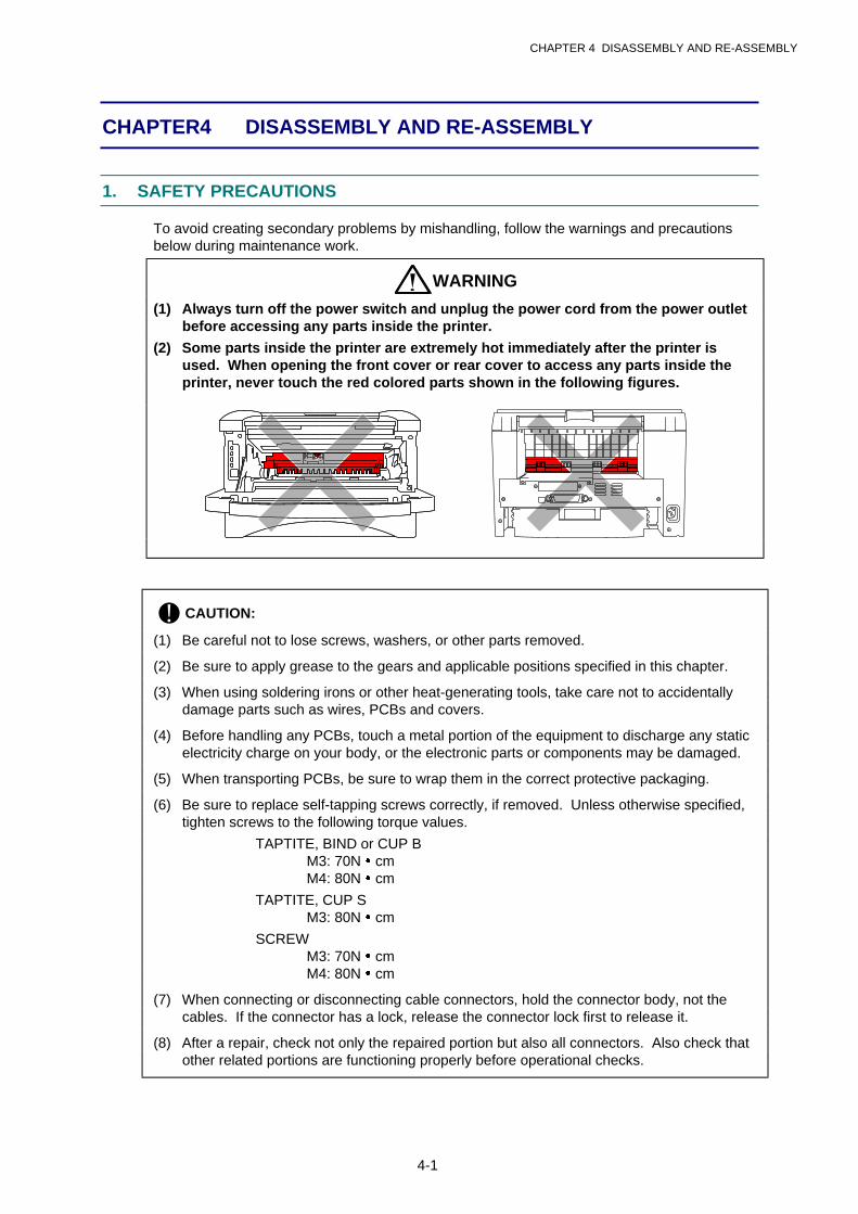
CHAPTER 4 DISASSEMBLY AND RE-ASSEMBLY
4-1
CHAPTER 4 DISASSEMBLY AND RE-ASSEMBLY
1. SAFETY PRECAUTIONS
To avoid creating secondary problems by mishandling, follow the warnings and precautionsbelow during maintenance work.
WARNING
(1) Always turn off the power switch and unplug the power cord from the power outletbefore accessing any parts inside the printer.
(2) Some parts inside the printer are extremely hot immediately after the printer isused. When opening the front cover or rear cover to access any parts inside theprinter, never touch the red colored parts shown in the following figures.
! CAUTION:
(1) Be careful not to lose screws, washers, or other parts removed.
(2) Be sure to apply grease to the gears and applicable positions specified in this chapter.
(3) When using soldering irons or other heat-generating tools, take care not to accidentallydamage parts such as wires, PCBs and covers.
(4) Before handling any PCBs, touch a metal portion of the equipment to discharge any staticelectricity charge on your body, or the electronic parts or components may be damaged.
(5) When transporting PCBs, be sure to wrap them in the correct protective packaging.
(6) Be sure to replace self-tapping screws correctly, if removed. Unless otherwise specified,tighten screws to the following torque values.
TAPTITE, BIND or CUP B M3: 70N � cm M4: 80N � cm
TAPTITE, CUP S M3: 80N � cm
SCREW M3: 70N � cm M4: 80N � cm
(7) When connecting or disconnecting cable connectors, hold the connector body, not thecables. If the connector has a lock, release the connector lock first to release it.
(8) After a repair, check not only the repaired portion but also all connectors. Also check thatother related portions are functioning properly before operational checks.
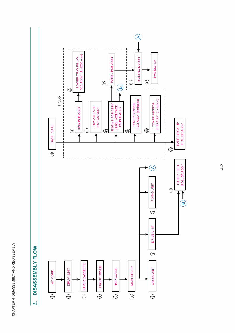
CH
AP
TE
R 4
DIS
AS
SE
MB
LY A
ND
RE
-AS
SE
MB
LY
4-2
2.
DIS
AS
SE
MB
LY
FL
OW
1A
C C
OR
D
DR
UM
UN
IT2
PA
PE
R C
AS
SE
TT
E3
MA
IN C
OV
ER
64F
RO
NT
CO
VE
R
5T
OP
CO
VE
R
LAS
ER
UN
IT7
FIX
ING
UN
IT9
DR
IVE
UN
IT8
BA
SE
PLA
TE
10
PC
Bs
MA
IN P
CB
AS
SY
11
LOW
-VO
LTA
GE
PS
PC
B A
SS
Y
13 14 EN
GIN
E P
CB
AS
SY
/ HIG
H-V
OLT
AG
E P
S P
CB
AS
SY
12
LOW
ER
TR
AY
RE
LAY
PC
B A
SS
Y (
HL-
1250
onl
y)
20
PA
PE
R P
ICK
-UP
RO
LLE
R A
SS
Y
18
TO
NE
R S
EN
SO
R P
CB
AS
SY
(em
issi
on)
19
TO
NE
R S
EN
SO
R P
CB
AS
SY
(re
cept
ion)
PA
NE
L P
CB
AS
SY
15
SO
LEN
OID
AS
SY
16
FA
N M
OT
OR
17
A
A
B
B
21
PA
PE
R F
EE
DR
OLL
ER
AS
SY
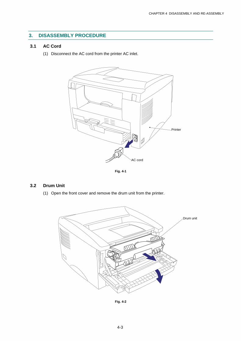
CHAPTER 4 DISASSEMBLY AND RE-ASSEMBLY
4-3
3. DISASSEMBLY PROCEDURE
3.1 AC Cord
(1) Disconnect the AC cord from the printer AC inlet.
Fig. 4-1
3.2 Drum Unit
(1) Open the front cover and remove the drum unit from the printer.
Fig. 4-2
Printer
AC cord
Drum unit

CHAPTER 4 DISASSEMBLY AND RE-ASSEMBLY
4-4
3.3 Paper Cassette
(1) Close the front cover, pull out the paper cassette from the printer and remove the paperfrom the cassette.
Fig. 4-3
(2) Remove the separation pad holder ASSY by pulling it upwards, then remove theseparation pad spring from the paper cassette.
Fig. 4-4
Paper cassette
Paper cassette Separation pad spring
Separation pad holder
Front cover
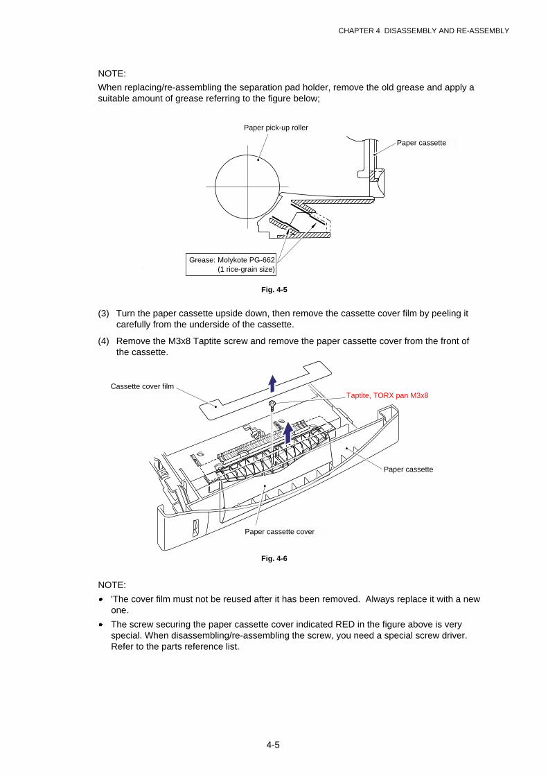
CHAPTER 4 DISASSEMBLY AND RE-ASSEMBLY
4-5
NOTE:
When replacing/re-assembling the separation pad holder, remove the old grease and apply asuitable amount of grease referring to the figure below;
Fig. 4-5
(3) Turn the paper cassette upside down, then remove the cassette cover film by peeling itcarefully from the underside of the cassette.
(4) Remove the M3x8 Taptite screw and remove the paper cassette cover from the front ofthe cassette.
Fig. 4-6
NOTE:
· 'The cover film must not be reused after it has been removed. Always replace it with a newone.
· The screw securing the paper cassette cover indicated RED in the figure above is veryspecial. When disassembling/re-assembling the screw, you need a special screw driver.Refer to the parts reference list.
Paper cassette
Paper pick-up roller
Taptite, TORX pan M3x8Cassette cover film
Grease: Molykote PG-662(1 rice-grain size)
Paper cassette cover
Paper cassette
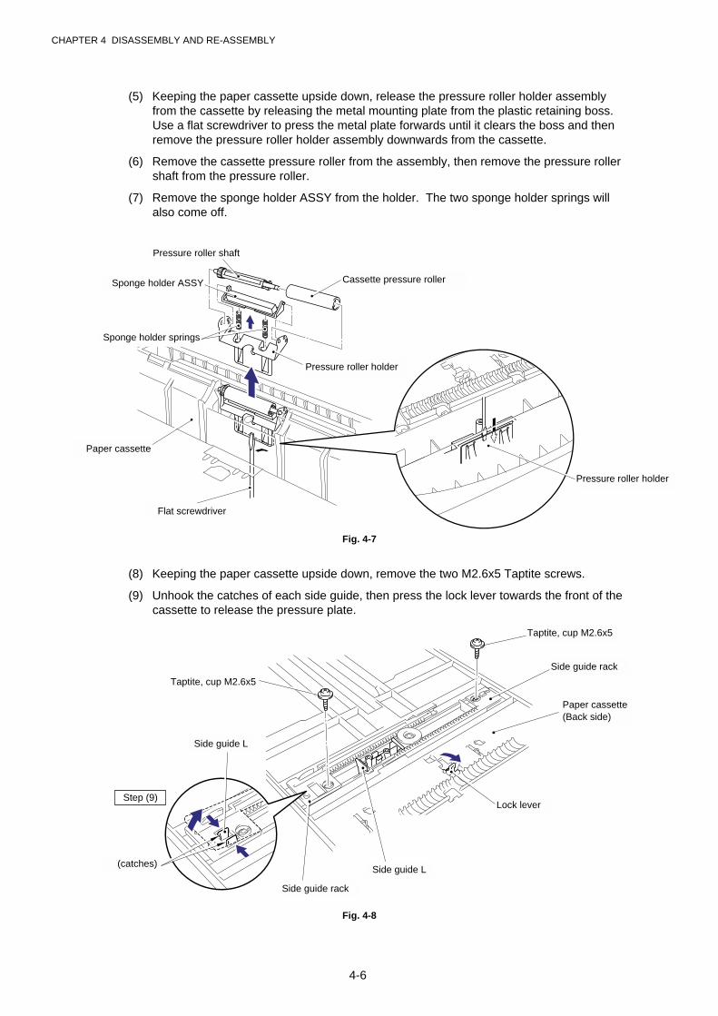
CHAPTER 4 DISASSEMBLY AND RE-ASSEMBLY
4-6
(5) Keeping the paper cassette upside down, release the pressure roller holder assemblyfrom the cassette by releasing the metal mounting plate from the plastic retaining boss.Use a flat screwdriver to press the metal plate forwards until it clears the boss and thenremove the pressure roller holder assembly downwards from the cassette.
(6) Remove the cassette pressure roller from the assembly, then remove the pressure rollershaft from the pressure roller.
(7) Remove the sponge holder ASSY from the holder. The two sponge holder springs willalso come off.
Fig. 4-7
(8) Keeping the paper cassette upside down, remove the two M2.6x5 Taptite screws.
(9) Unhook the catches of each side guide, then press the lock lever towards the front of thecassette to release the pressure plate.
Fig. 4-8
Cassette pressure roller
Pressure roller holder
Paper cassette
Taptite, cup M2.6x5
Taptite, cup M2.6x5
Side guide rack
Pressure roller shaft
(catches)
Sponge holder ASSY
Lock lever
Sponge holder springs
Paper cassette(Back side)
Pressure roller holder
Flat screwdriver
Step (9)
Side guide L
Side guide rack
Side guide L
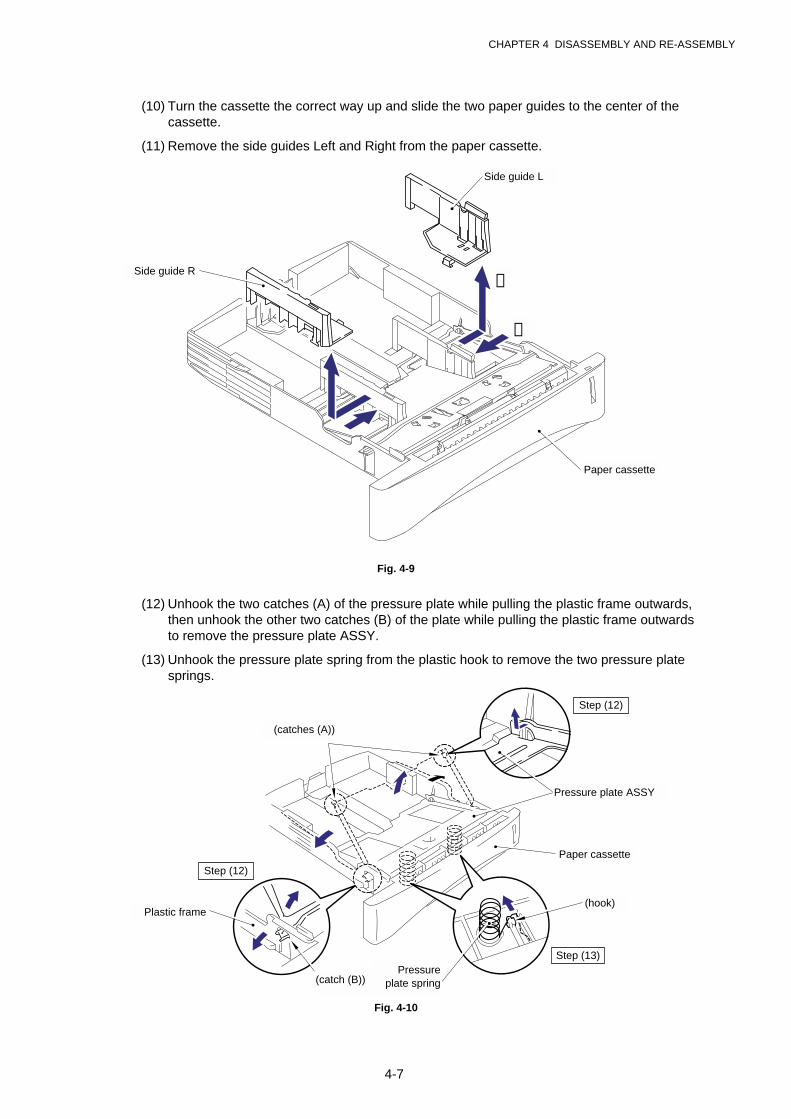
CHAPTER 4 DISASSEMBLY AND RE-ASSEMBLY
4-7
(10) Turn the cassette the correct way up and slide the two paper guides to the center of thecassette.
(11) Remove the side guides Left and Right from the paper cassette.
Fig. 4-9
(12) Unhook the two catches (A) of the pressure plate while pulling the plastic frame outwards,then unhook the other two catches (B) of the plate while pulling the plastic frame outwardsto remove the pressure plate ASSY.
(13) Unhook the pressure plate spring from the plastic hook to remove the two pressure platesprings.
Fig. 4-10
Pressure plate ASSY
Pressureplate spring
Paper cassette
(hook)Plastic frame
Step (12)
Step (13)
(catches (A))
Step (12)
(catch (B))
Side guide L
Side guide R
Paper cassette
➀
➁
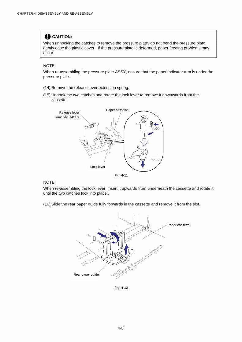
CHAPTER 4 DISASSEMBLY AND RE-ASSEMBLY
4-8
! CAUTION:
When unhooking the catches to remove the pressure plate, do not bend the pressure plate,gently ease the plastic cover. If the pressure plate is deformed, paper feeding problems mayoccur.
NOTE:
When re-assembling the pressure plate ASSY, ensure that the paper indicator arm is under thepressure plate.
(14) Remove the release lever extension spring.
(15) Unhook the two catches and rotate the lock lever to remove it downwards from thecassette.
Fig. 4-11
NOTE:
When re-assembling the lock lever, insert it upwards from underneath the cassette and rotate ituntil the two catches lock into place..
(16) Slide the rear paper guide fully forwards in the cassette and remove it from the slot.
Fig. 4-12
Paper cassette
Rear paper guide
Release leverextension spring
Paper cassette
Lock lever
➀
➁
➂
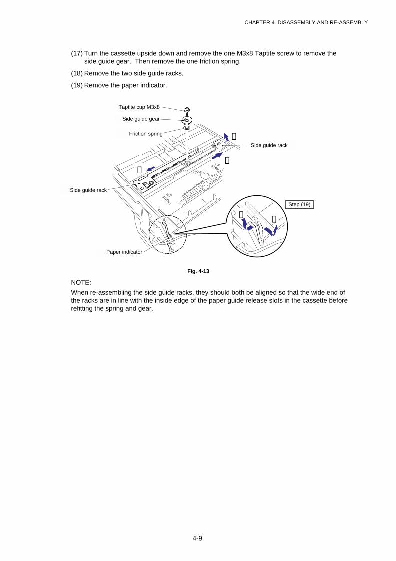
CHAPTER 4 DISASSEMBLY AND RE-ASSEMBLY
4-9
(17) Turn the cassette upside down and remove the one M3x8 Taptite screw to remove theside guide gear. Then remove the one friction spring.
(18) Remove the two side guide racks.
(19) Remove the paper indicator.
Fig. 4-13
NOTE:
When re-assembling the side guide racks, they should both be aligned so that the wide end ofthe racks are in line with the inside edge of the paper guide release slots in the cassette beforerefitting the spring and gear.
Taptite cup M3x8
Side guide gear
Friction spring
Side guide rack
Side guide rack
Paper indicator
➀ ➁
Step (19)
➀➀
➁
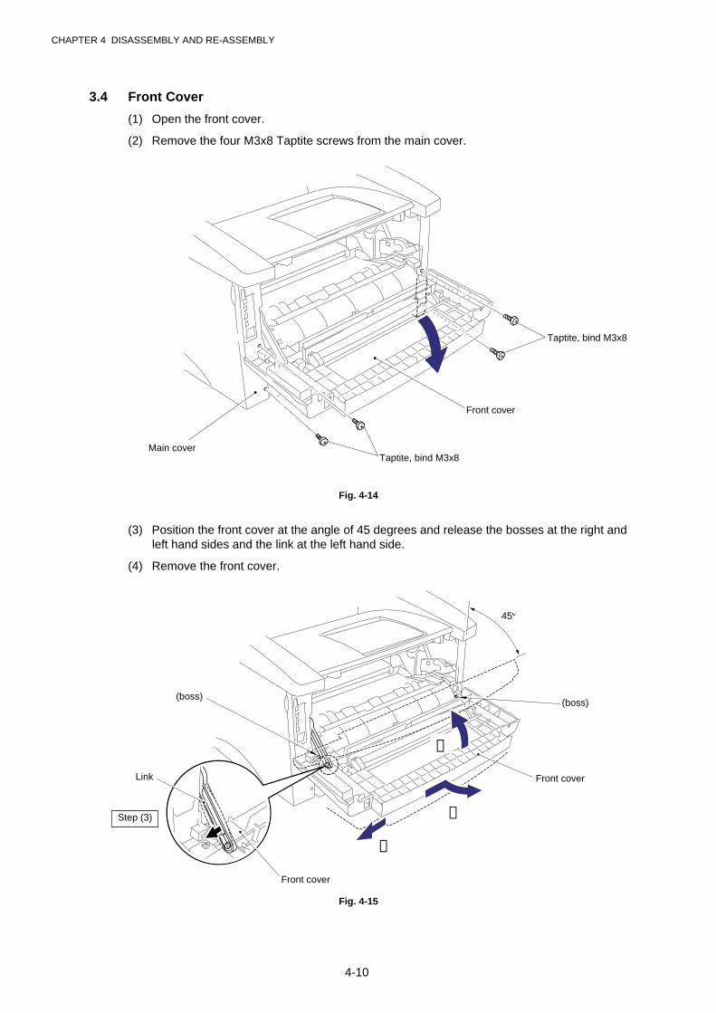
CHAPTER 4 DISASSEMBLY AND RE-ASSEMBLY
4-10
3.4 Front Cover
(1) Open the front cover.
(2) Remove the four M3x8 Taptite screws from the main cover.
Fig. 4-14
(3) Position the front cover at the angle of 45 degrees and release the bosses at the right andleft hand sides and the link at the left hand side.
(4) Remove the front cover.
Fig. 4-15
Front cover
Taptite, bind M3x8
Taptite, bind M3x8
Front cover
Front cover
Link
45°
(boss)(boss)
Main cover
➀
➂
➁
Step (3)
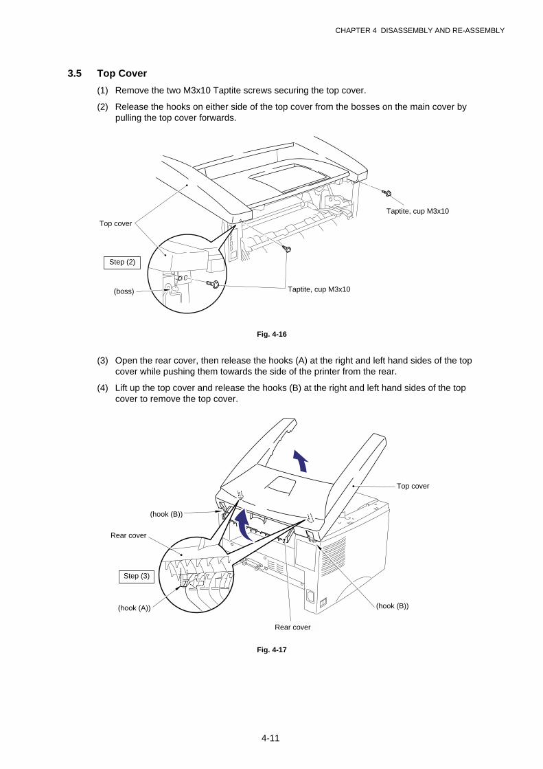
CHAPTER 4 DISASSEMBLY AND RE-ASSEMBLY
4-11
3.5 Top Cover
(1) Remove the two M3x10 Taptite screws securing the top cover.
(2) Release the hooks on either side of the top cover from the bosses on the main cover bypulling the top cover forwards.
Fig. 4-16
(3) Open the rear cover, then release the hooks (A) at the right and left hand sides of the topcover while pushing them towards the side of the printer from the rear.
(4) Lift up the top cover and release the hooks (B) at the right and left hand sides of the topcover to remove the top cover.
Fig. 4-17
Taptite, cup M3x10
Taptite, cup M3x10
Top cover
Step (2)
Top cover
(hook (B))
(hook (B))(hook (A))
Rear cover
Step (3)
Rear cover
(boss)
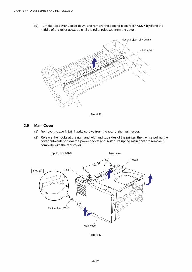
CHAPTER 4 DISASSEMBLY AND RE-ASSEMBLY
4-12
(5) Turn the top cover upside down and remove the second eject roller ASSY by lifting themiddle of the roller upwards until the roller releases from the cover.
Fig. 4-18
3.6 Main Cover
(1) Remove the two M3x8 Taptite screws from the rear of the main cover.
(2) Release the hooks at the right and left hand top sides of the printer, then, while pulling thecover outwards to clear the power socket and switch, lift up the main cover to remove itcomplete with the rear cover.
Fig. 4-19
Top cover
Second eject roller ASSY
Rear cover
Taptite, bind M3x8
(hook)
(hook)
Main cover
Step (1)
Taptite, bind M3x8
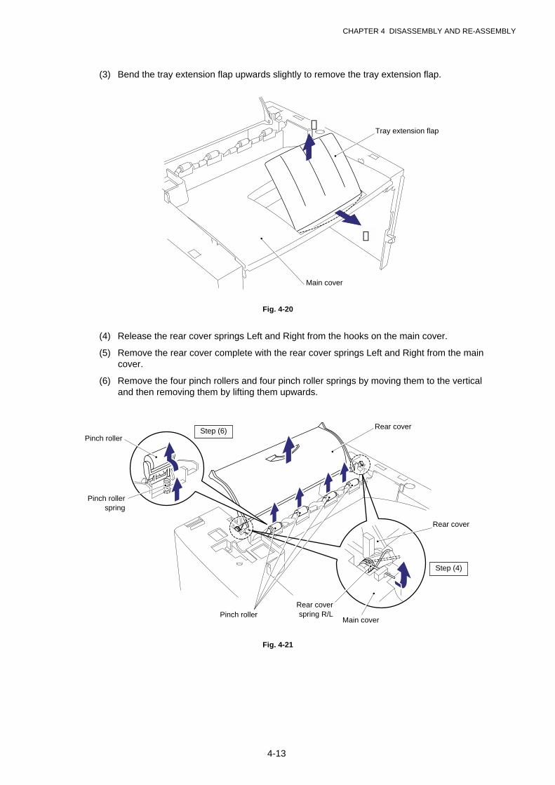
CHAPTER 4 DISASSEMBLY AND RE-ASSEMBLY
4-13
(3) Bend the tray extension flap upwards slightly to remove the tray extension flap.
Fig. 4-20
(4) Release the rear cover springs Left and Right from the hooks on the main cover.
(5) Remove the rear cover complete with the rear cover springs Left and Right from the maincover.
(6) Remove the four pinch rollers and four pinch roller springs by moving them to the verticaland then removing them by lifting them upwards.
Fig. 4-21
Tray extension flap
Main cover
➀
Rear cover
➁
Rear cover
Main cover
Rear coverspring R/LPinch roller
Pinch rollerspring
Pinch roller
Step (4)
Step (6)
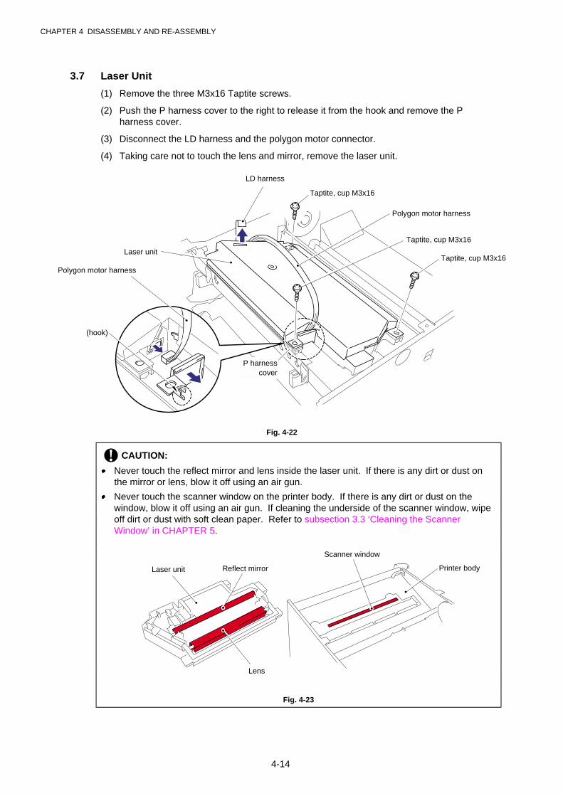
CHAPTER 4 DISASSEMBLY AND RE-ASSEMBLY
4-14
3.7 Laser Unit
(1) Remove the three M3x16 Taptite screws.
(2) Push the P harness cover to the right to release it from the hook and remove the Pharness cover.
(3) Disconnect the LD harness and the polygon motor connector.
(4) Taking care not to touch the lens and mirror, remove the laser unit.
Fig. 4-22
! CAUTION:
· Never touch the reflect mirror and lens inside the laser unit. If there is any dirt or dust onthe mirror or lens, blow it off using an air gun.
· Never touch the scanner window on the printer body. If there is any dirt or dust on thewindow, blow it off using an air gun. If cleaning the underside of the scanner window, wipeoff dirt or dust with soft clean paper. Refer to subsection 3.3 ‘Cleaning the ScannerWindow’ in CHAPTER 5.
Fig. 4-23
Taptite, cup M3x16
Polygon motor harness
Taptite, cup M3x16
Taptite, cup M3x16Laser unit
P harnesscover
(hook)
Laser unit
LD harness
Reflect mirror
Polygon motor harness
Lens
Scanner window
Printer body
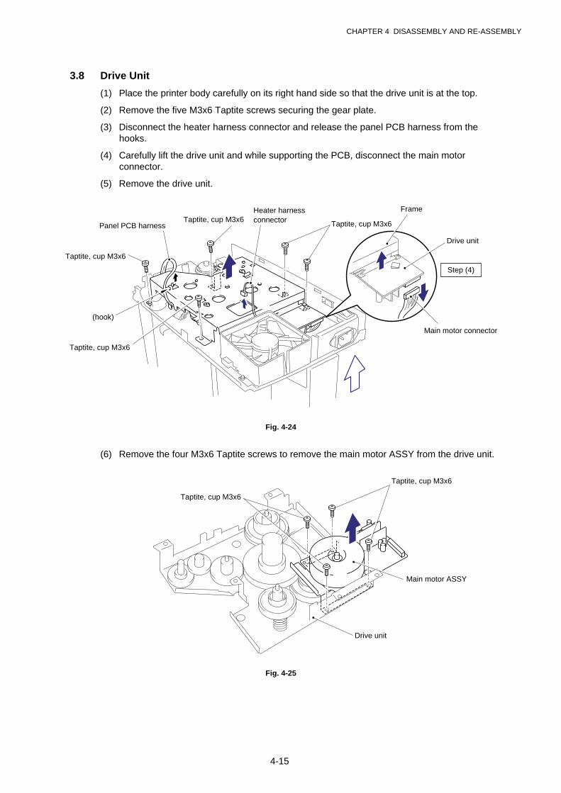
CHAPTER 4 DISASSEMBLY AND RE-ASSEMBLY
4-15
3.8 Drive Unit
(1) Place the printer body carefully on its right hand side so that the drive unit is at the top.
(2) Remove the five M3x6 Taptite screws securing the gear plate.
(3) Disconnect the heater harness connector and release the panel PCB harness from thehooks.
(4) Carefully lift the drive unit and while supporting the PCB, disconnect the main motorconnector.
(5) Remove the drive unit.
Fig. 4-24
(6) Remove the four M3x6 Taptite screws to remove the main motor ASSY from the drive unit.
Fig. 4-25
Taptite, cup M3x6
Taptite, cup M3x6
Taptite, cup M3x6
Taptite, cup M3x6
Taptite, cup M3x6
Main motor ASSY
Main motor connector
Drive unit
Heater harnessconnector
Panel PCB harness
Drive unit
Frame
Taptite, cup M3x6
(hook)
Step (4)
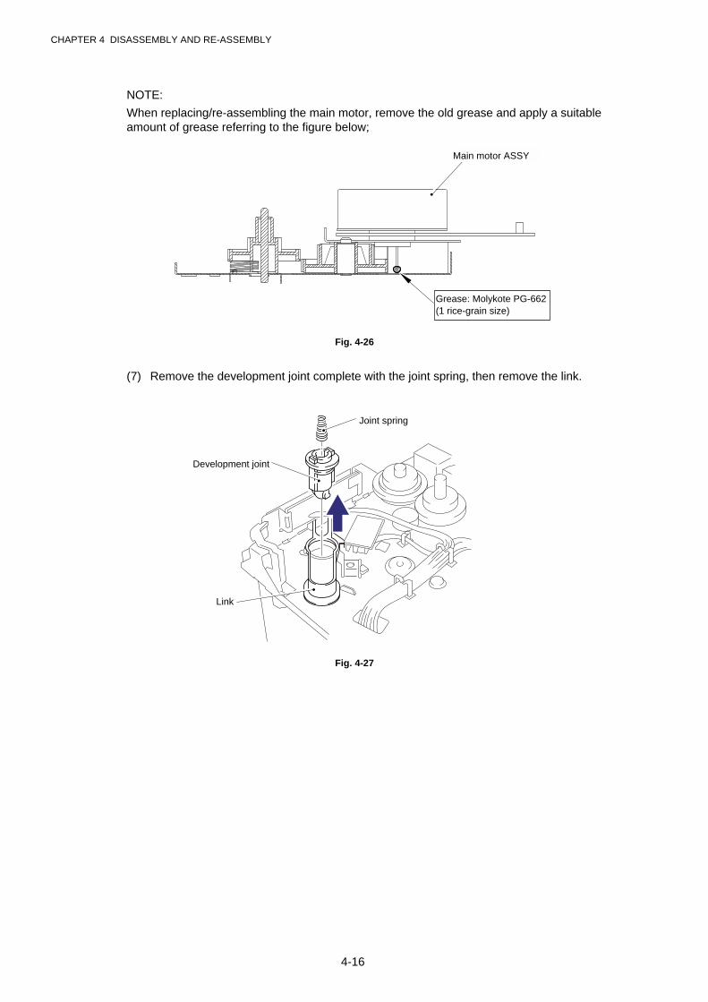
CHAPTER 4 DISASSEMBLY AND RE-ASSEMBLY
4-16
NOTE:
When replacing/re-assembling the main motor, remove the old grease and apply a suitableamount of grease referring to the figure below;
Fig. 4-26
(7) Remove the development joint complete with the joint spring, then remove the link.
Fig. 4-27
Grease: Molykote PG-662(1 rice-grain size)
Joint spring
Development joint
Link
Main motor ASSY
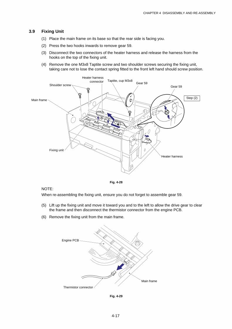
CHAPTER 4 DISASSEMBLY AND RE-ASSEMBLY
4-17
3.9 Fixing Unit
(1) Place the main frame on its base so that the rear side is facing you.
(2) Press the two hooks inwards to remove gear 59.
(3) Disconnect the two connectors of the heater harness and release the harness from thehooks on the top of the fixing unit.
(4) Remove the one M3x8 Taptite screw and two shoulder screws securing the fixing unit,taking care not to lose the contact spring fitted to the front left hand should screw position.
Fig. 4-28
NOTE:
When re-assembling the fixing unit, ensure you do not forget to assemble gear 59.
(5) Lift up the fixing unit and move it toward you and to the left to allow the drive gear to clearthe frame and then disconnect the thermistor connector from the engine PCB.
(6) Remove the fixing unit from the main frame.
Fig. 4-29
Shoulder screw
Thermistor connector
Main frame
Engine PCB
Heater harnessconnector
Main frame
Heater harness
Gear 59Gear 59
Fixing unit
Taptite, cup M3x8
Step (2)

CHAPTER 4 DISASSEMBLY AND RE-ASSEMBLY
4-18
NOTE:
When re-assembling the fixing unit, align the fixing unit frame at the drive unit side into theconcave part of the main frame.
Fig. 4-30
(7) Remove the M3x10 screw to remove the star wheel holder ASSY from the fixing unit bylifting the left hand end of the assembly slightly and then moving the assembly to the rightto release the right hand end from the fixing unit frame.
Fig. 4-31
Main frame
Fixing unit
(concavity)
Fixing unit
Main frame
Fixing unit
Star wheel holder ASSY
Screw, bind M3x10
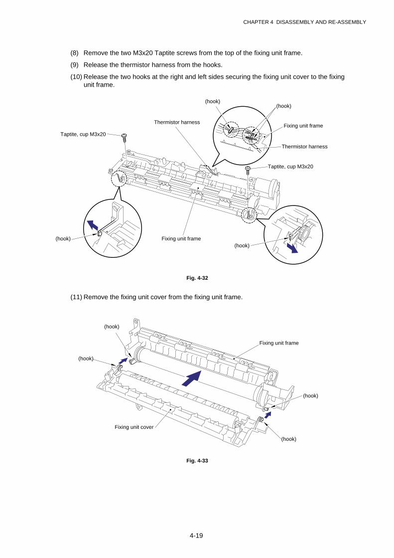
CHAPTER 4 DISASSEMBLY AND RE-ASSEMBLY
4-19
(8) Remove the two M3x20 Taptite screws from the top of the fixing unit frame.
(9) Release the thermistor harness from the hooks.
(10) Release the two hooks at the right and left sides securing the fixing unit cover to the fixingunit frame.
Fig. 4-32
(11) Remove the fixing unit cover from the fixing unit frame.
Fig. 4-33
Fixing unit frame
Fixing unit cover
(hook)
(hook)
(hook)
(hook)
Fixing unit frame
(hook)
Thermistor harness
(hook)
Taptite, cup M3x20
Thermistor harness
Taptite, cup M3x20
Fixing unit frame(hook)
(hook)
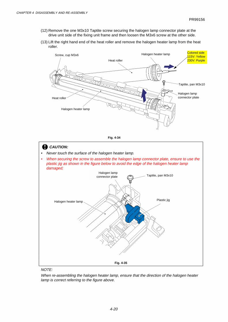
CHAPTER 4 DISASSEMBLY AND RE-ASSEMBLY
4-20
(12) Remove the one M3x10 Taptite screw securing the halogen lamp connector plate at thedrive unit side of the fixing unit frame and then loosen the M3x6 screw at the other side.
(13) Lift the right hand end of the heat roller and remove the halogen heater lamp from the heatroller.
Fig. 4-34
! CAUTION:
• Never touch the surface of the halogen heater lamp.
• When securing the screw to assemble the halogen lamp connector plate, ensure to use theplastic jig as shown in the figure below to avoid the edge of the halogen heater lampdamaged;
Fig. 4-35
NOTE:
When re-assembling the halogen heater lamp, ensure that the direction of the halogen heaterlamp is correct referring to the figure above.
Halogen heater lamp
Heat roller
Taptite, pan M3x10
Screw, cup M3x6
Halogen heater lamp
Heat roller
Colored side115V: Yellow230V: Purple
Halogen lampconnector plate
PR99156
Taptite, pan M3x10Halogen lamp
connector plate
Plastic jigHalogen heater lamp

CHAPTER 4 DISASSEMBLY AND RE-ASSEMBLY
4-20A
(14) Lift and remove the heat roller. The heat roller gear will also come off.
(15) Remove the heat roller bearing from the left hand end of the heat roller. To remove thebearing at the gear side, first remove the washer, then remove the bearing.
Fig. 4-36
Heat roller
Heat roller bearing
Heat roller gear
Heat roller bearing
Washer
PR99156
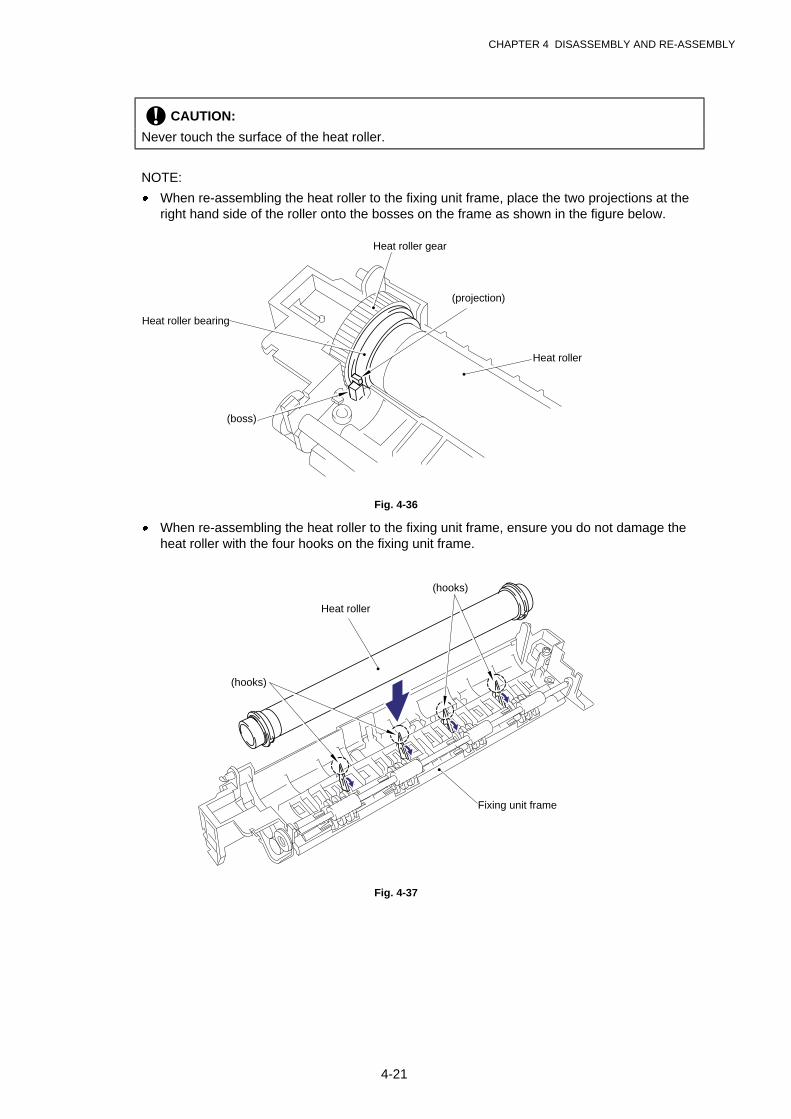
CHAPTER 4 DISASSEMBLY AND RE-ASSEMBLY
4-21
! CAUTION:
Never touch the surface of the heat roller.
NOTE:
· When re-assembling the heat roller to the fixing unit frame, place the two projections at theright hand side of the roller onto the bosses on the frame as shown in the figure below.
Fig. 4-36
· When re-assembling the heat roller to the fixing unit frame, ensure you do not damage theheat roller with the four hooks on the fixing unit frame.
Fig. 4-37
Heat roller
Fixing unit frame
(hooks)
(hooks)
Heat roller gear
Heat roller bearing
Heat roller
(projection)
(boss)
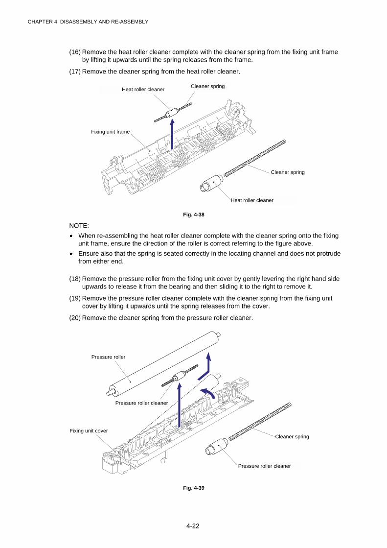
CHAPTER 4 DISASSEMBLY AND RE-ASSEMBLY
4-22
(16) Remove the heat roller cleaner complete with the cleaner spring from the fixing unit frameby lifting it upwards until the spring releases from the frame.
(17) Remove the cleaner spring from the heat roller cleaner.
Fig. 4-38
NOTE:
· When re-assembling the heat roller cleaner complete with the cleaner spring onto the fixingunit frame, ensure the direction of the roller is correct referring to the figure above.
· Ensure also that the spring is seated correctly in the locating channel and does not protrudefrom either end.
(18) Remove the pressure roller from the fixing unit cover by gently levering the right hand sideupwards to release it from the bearing and then sliding it to the right to remove it.
(19) Remove the pressure roller cleaner complete with the cleaner spring from the fixing unitcover by lifting it upwards until the spring releases from the cover.
(20) Remove the cleaner spring from the pressure roller cleaner.
Fig. 4-39
Cleaner spring
Heat roller cleaner
Fixing unit frame
Cleaner spring
Pressure roller cleaner
Fixing unit cover
Pressure roller
Heat roller cleanerCleaner spring
Pressure roller cleaner
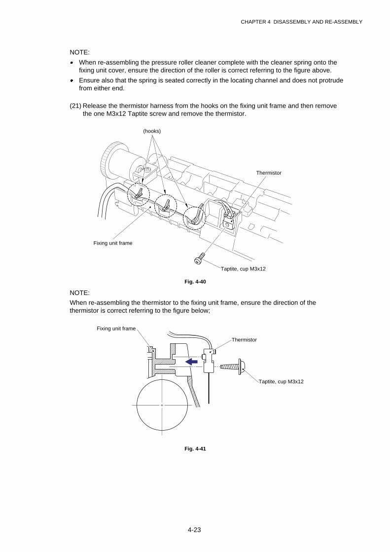
CHAPTER 4 DISASSEMBLY AND RE-ASSEMBLY
4-23
NOTE:
· When re-assembling the pressure roller cleaner complete with the cleaner spring onto thefixing unit cover, ensure the direction of the roller is correct referring to the figure above.
· Ensure also that the spring is seated correctly in the locating channel and does not protrudefrom either end.
(21) Release the thermistor harness from the hooks on the fixing unit frame and then removethe one M3x12 Taptite screw and remove the thermistor.
Fig. 4-40
NOTE:
When re-assembling the thermistor to the fixing unit frame, ensure the direction of thethermistor is correct referring to the figure below;
Fig. 4-41
Thermistor
Taptite, cup M3x12
Fixing unit frame
(hooks)
Thermistor
Taptite, cup M3x12
Fixing unit frame
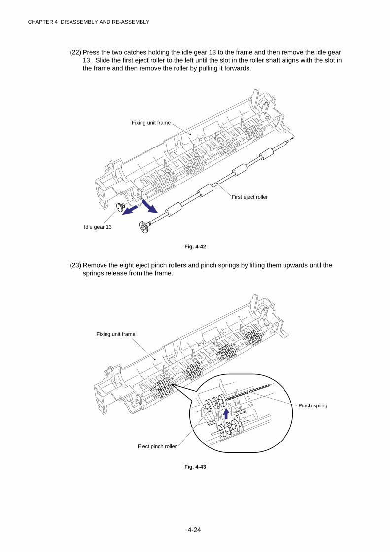
CHAPTER 4 DISASSEMBLY AND RE-ASSEMBLY
4-24
(22) Press the two catches holding the idle gear 13 to the frame and then remove the idle gear13. Slide the first eject roller to the left until the slot in the roller shaft aligns with the slot inthe frame and then remove the roller by pulling it forwards.
Fig. 4-42
(23) Remove the eight eject pinch rollers and pinch springs by lifting them upwards until thesprings release from the frame.
Fig. 4-43
Fixing unit frame
Idle gear 13
First eject roller
Fixing unit frame
Pinch spring
Eject pinch roller
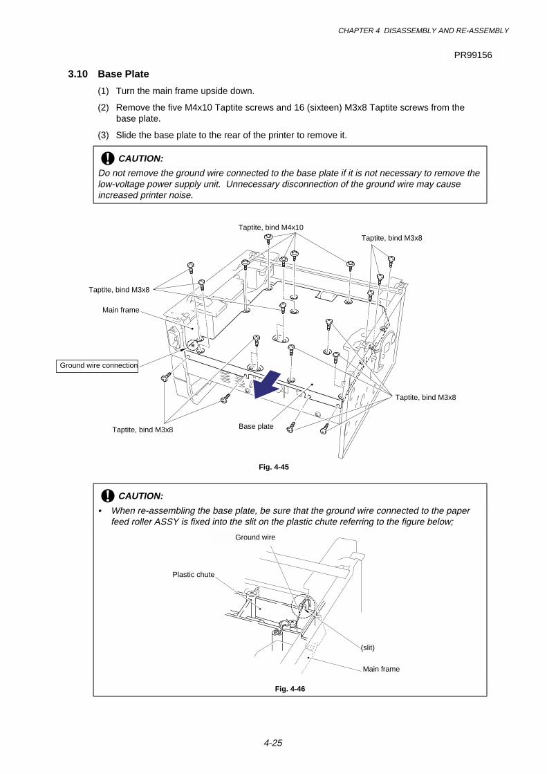
CHAPTER 4 DISASSEMBLY AND RE-ASSEMBLY
4-25
3.10 Base Plate
(1) Turn the main frame upside down.
(2) Remove the five M4x10 Taptite screws and 16 (sixteen) M3x8 Taptite screws from thebase plate.
(3) Slide the base plate to the rear of the printer to remove it.
! CAUTION:
Do not remove the ground wire connected to the base plate if it is not necessary to remove thelow-voltage power supply unit. Unnecessary disconnection of the ground wire may causeincreased printer noise.
Fig. 4-45
! CAUTION:
• When re-assembling the base plate, be sure that the ground wire connected to the paperfeed roller ASSY is fixed into the slit on the plastic chute referring to the figure below;
Fig. 4-46
Taptite, bind M4x10Taptite, bind M3x8
Taptite, bind M3x8
Taptite, bind M3x8
Taptite, bind M3x8 Base plate
Main frame
Ground wire connection
(slit)
Ground wire
Plastic chute
Main frame
PR99156
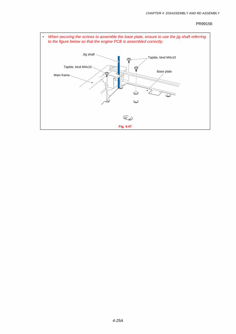
CHAPTER 4 DISASSEMBLY AND RE-ASSEMBLY
4-25A
• When securing the screws to assemble the base plate, ensure to use the jig shaft referringto the figure below so that the engine PCB is assembled correctly;
Fig. 4-47
PR99156
Taptite, bind M4x10
Taptite, bind M4x10
Main frameBase plate
Jig shaft

CHAPTER 4 DISASSEMBLY AND RE-ASSEMBLY
4-26
3.11 Main PCB ASSY
(1) Remove the two M3x8 screws from the I/F plate to release the main PCB.
(2) Lift the insulation sheet and remove the main PCB ASSY.
(3) Disconnect the three connectors for the low-voltage power supply, engine PCB and LD.
Fig. 4-46
3.12 Lower Tray Relay PCB ASSY (For HL-1250 only)
(1) Remove the M3x6 Taptite screw and remove the lower tray relay PCB ASSY.
Fig. 4-47
Taptite, cup M3x6
Lower tray relayPCB ASSY
Lower tray relay PCB ASSY
Main frame
Screw M3x8
Insulation sheet
Main PCB
Low-voltage power supply connector
Engine PCB connectorLD connector
I/F plate
➀
➁
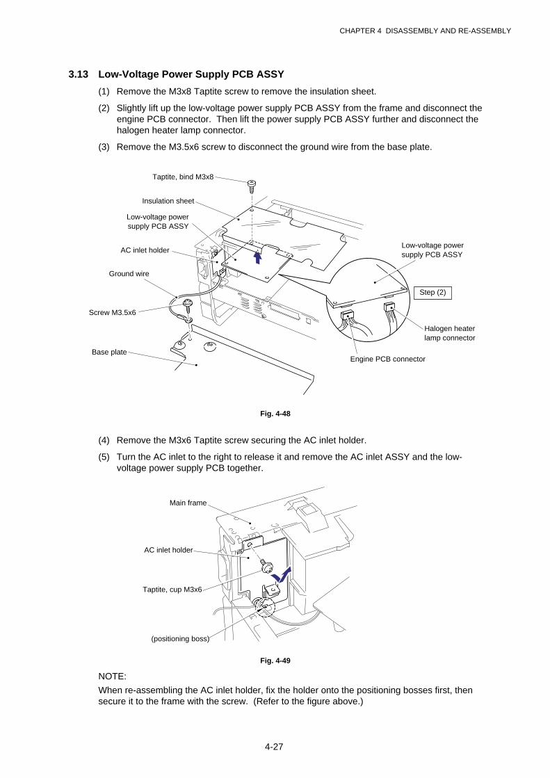
CHAPTER 4 DISASSEMBLY AND RE-ASSEMBLY
4-27
3.13 Low-Voltage Power Supply PCB ASSY
(1) Remove the M3x8 Taptite screw to remove the insulation sheet.
(2) Slightly lift up the low-voltage power supply PCB ASSY from the frame and disconnect theengine PCB connector. Then lift the power supply PCB ASSY further and disconnect thehalogen heater lamp connector.
(3) Remove the M3.5x6 screw to disconnect the ground wire from the base plate.
Fig. 4-48
(4) Remove the M3x6 Taptite screw securing the AC inlet holder.
(5) Turn the AC inlet to the right to release it and remove the AC inlet ASSY and the low-voltage power supply PCB together.
Fig. 4-49
NOTE:
When re-assembling the AC inlet holder, fix the holder onto the positioning bosses first, thensecure it to the frame with the screw. (Refer to the figure above.)
Taptite, bind M3x8
AC inlet holder
Low-voltage powersupply PCB ASSY
Ground wire
Screw M3.5x6
Halogen heaterlamp connector
Engine PCB connector
Low-voltage powersupply PCB ASSY
Base plate
Taptite, cup M3x6
AC inlet holder
Main frame
(positioning boss)
Insulation sheet
Step (2)

CHAPTER 4 DISASSEMBLY AND RE-ASSEMBLY
4-28
3.14 Engine PCB ASSY / High-Voltage Power Supply PCB ASSY
(1) Remove the M4x12 Taptite screw to remove the insulation sheet.
(2) Remove the three M4x12 Taptite screws securing the engine PCB and the high-voltagepower supply PCB.
(3) Lift the engine PCB and high-voltage power supply PCB together and disconnect theconnector which connects two PCBs together to remove the high-voltage power supplyPCB ASSY.
(4) If necessary, remove the T/R electrode helical spring from the T/R plate.
Fig. 4-50
! CAUTION:
Be sure not to lose the T/R electrode helical spring after removing it.
NOTE:
When re-assembling the T/R electrode helical spring onto the plate, press the spring onto theplate firmly with a flat bladed screwdriver and ensure that it is retained securely.
Screw, bind M4x12
Screw, bind M4x12Engine PCB ASSY
High-voltage powersupply PCB ASSY
T/R electrodehelical spring
T/R plate
Insulation sheet
Screw, bind M4x12
Step (4)
Step (3)
PR99153
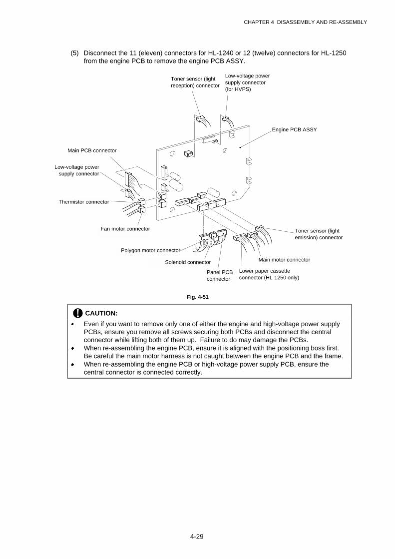
CHAPTER 4 DISASSEMBLY AND RE-ASSEMBLY
4-29
(5) Disconnect the 11 (eleven) connectors for HL-1240 or 12 (twelve) connectors for HL-1250from the engine PCB to remove the engine PCB ASSY.
Fig. 4-51
! CAUTION:
· Even if you want to remove only one of either the engine and high-voltage power supplyPCBs, ensure you remove all screws securing both PCBs and disconnect the centralconnector while lifting both of them up. Failure to do may damage the PCBs.
· When re-assembling the engine PCB, ensure it is aligned with the positioning boss first.Be careful the main motor harness is not caught between the engine PCB and the frame.
· When re-assembling the engine PCB or high-voltage power supply PCB, ensure thecentral connector is connected correctly.
Main PCB connector
Toner sensor (lightemission) connector
Fan motor connector
Thermistor connector
Low-voltage powersupply connector
Polygon motor connector
Panel PCBconnector
Lower paper cassetteconnector (HL-1250 only)
Main motor connectorSolenoid connector
Engine PCB ASSY
Low-voltage powersupply connector(for HVPS)
Toner sensor (lightreception) connector
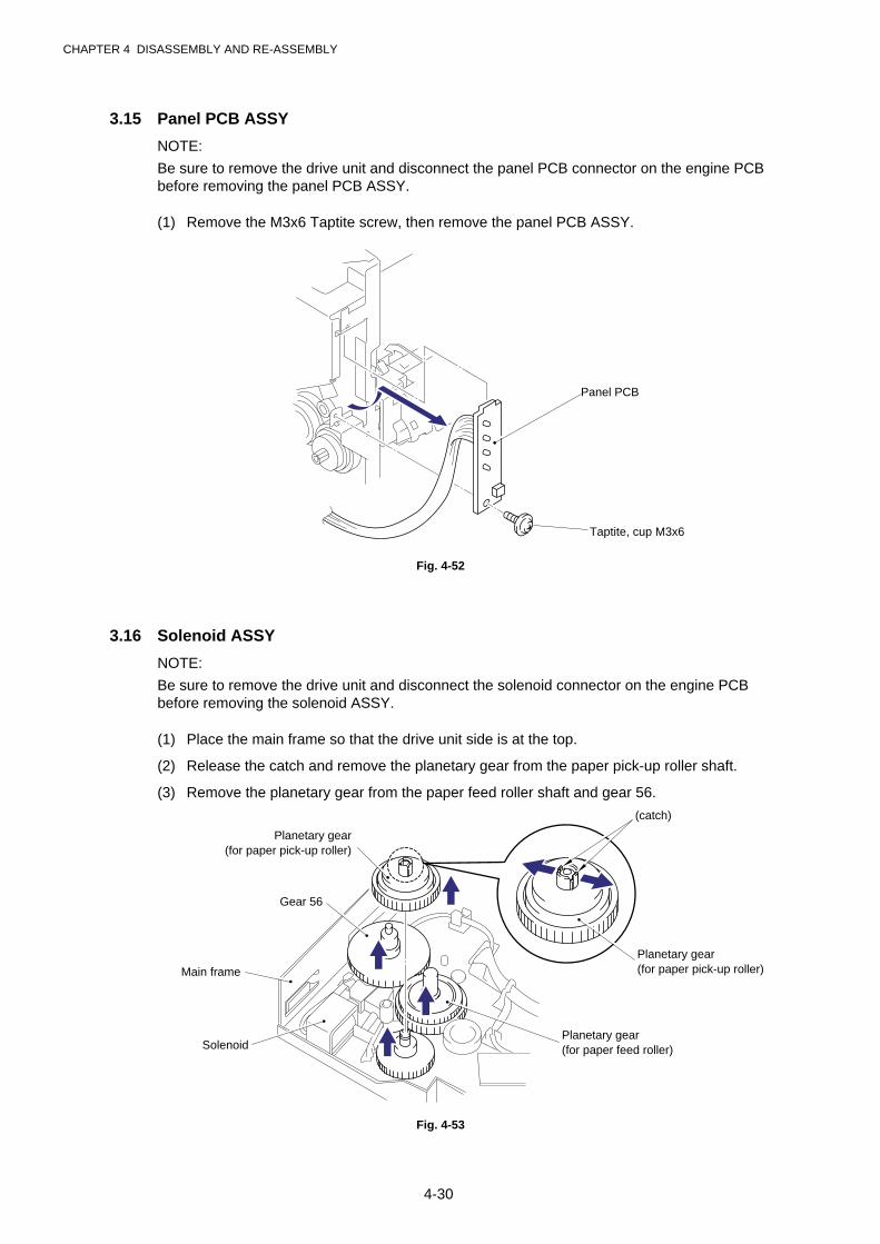
CHAPTER 4 DISASSEMBLY AND RE-ASSEMBLY
4-30
3.15 Panel PCB ASSY
NOTE:
Be sure to remove the drive unit and disconnect the panel PCB connector on the engine PCBbefore removing the panel PCB ASSY.
(1) Remove the M3x6 Taptite screw, then remove the panel PCB ASSY.
Fig. 4-52
3.16 Solenoid ASSY
NOTE:
Be sure to remove the drive unit and disconnect the solenoid connector on the engine PCBbefore removing the solenoid ASSY.
(1) Place the main frame so that the drive unit side is at the top.
(2) Release the catch and remove the planetary gear from the paper pick-up roller shaft.
(3) Remove the planetary gear from the paper feed roller shaft and gear 56.
Fig. 4-53
Planetary gear(for paper pick-up roller)
Planetary gear(for paper feed roller)
(catch)
Gear 56
Main frame
Solenoid
Planetary gear(for paper pick-up roller)
Panel PCB
Taptite, cup M3x6
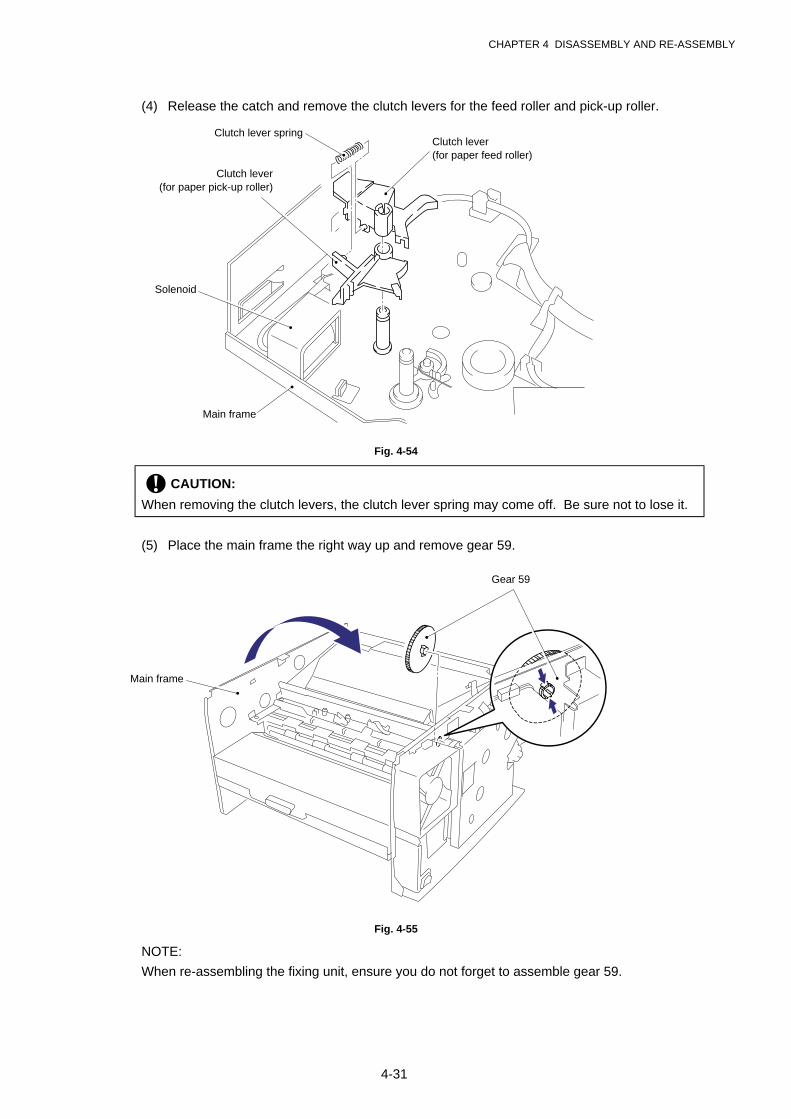
CHAPTER 4 DISASSEMBLY AND RE-ASSEMBLY
4-31
(4) Release the catch and remove the clutch levers for the feed roller and pick-up roller.
Fig. 4-54
! CAUTION:
When removing the clutch levers, the clutch lever spring may come off. Be sure not to lose it.
(5) Place the main frame the right way up and remove gear 59.
Fig. 4-55
NOTE:
When re-assembling the fixing unit, ensure you do not forget to assemble gear 59.
Clutch lever spring
Clutch lever(for paper pick-up roller)
Clutch lever(for paper feed roller)
Solenoid
Main frame
Gear 59
Main frame
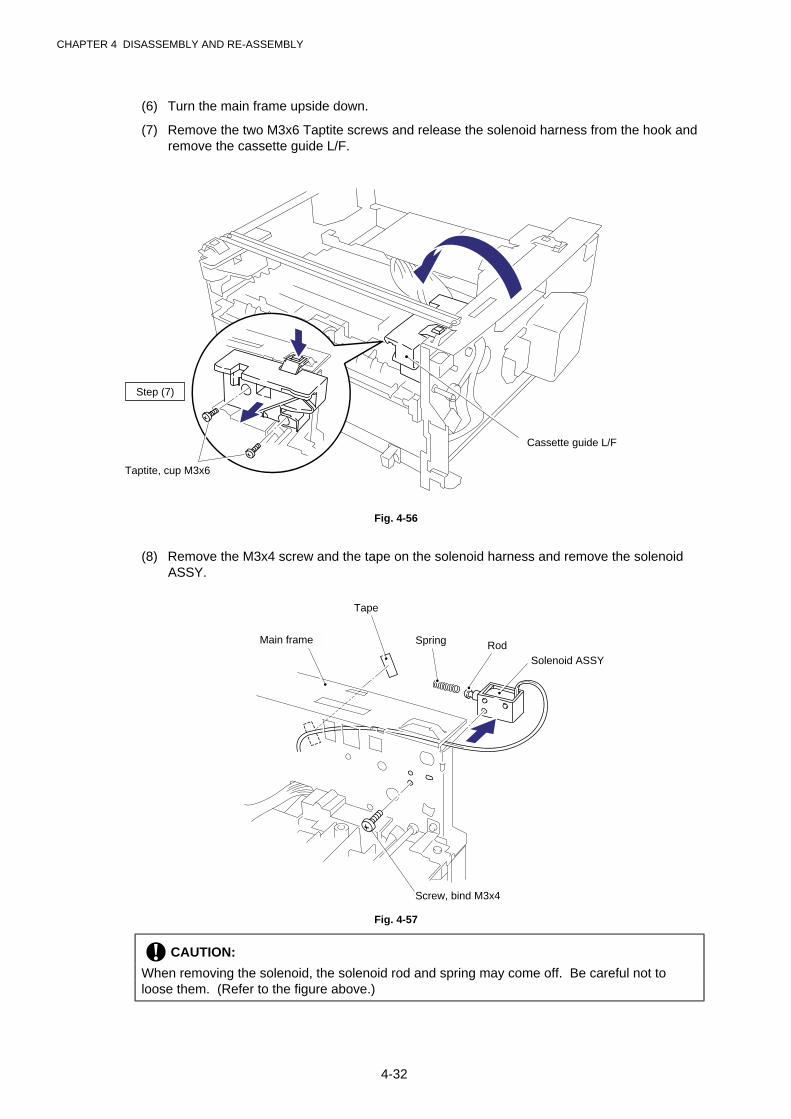
CHAPTER 4 DISASSEMBLY AND RE-ASSEMBLY
4-32
(6) Turn the main frame upside down.
(7) Remove the two M3x6 Taptite screws and release the solenoid harness from the hook andremove the cassette guide L/F.
Fig. 4-56
(8) Remove the M3x4 screw and the tape on the solenoid harness and remove the solenoidASSY.
Fig. 4-57
! CAUTION:
When removing the solenoid, the solenoid rod and spring may come off. Be careful not toloose them. (Refer to the figure above.)
Taptite, cup M3x6
Cassette guide L/F
Screw, bind M3x4
Solenoid ASSY
Main frame
Tape
Rod
Step (7)
Spring
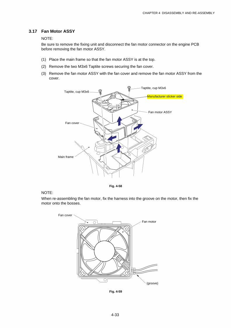
CHAPTER 4 DISASSEMBLY AND RE-ASSEMBLY
4-33
3.17 Fan Motor ASSY
NOTE:
Be sure to remove the fixing unit and disconnect the fan motor connector on the engine PCBbefore removing the fan motor ASSY.
(1) Place the main frame so that the fan motor ASSY is at the top.
(2) Remove the two M3x6 Taptite screws securing the fan cover.
(3) Remove the fan motor ASSY with the fan cover and remove the fan motor ASSY from thecover.
Fig. 4-58
NOTE:
When re-assembling the fan motor, fix the harness into the groove on the motor, then fix themotor onto the bosses.
Fig. 4-59
Taptite, cup M3x6Taptite, cup M3x6
Fan motor ASSY
Fan cover
Main frame
Manufacturer sticker side
Fan cover
(groove)
Fan motor
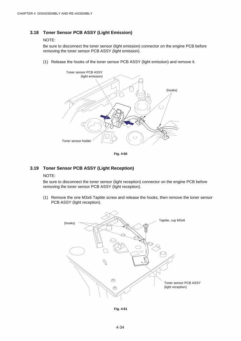
CHAPTER 4 DISASSEMBLY AND RE-ASSEMBLY
4-34
3.18 Toner Sensor PCB ASSY (Light Emission)
NOTE:
Be sure to disconnect the toner sensor (light emission) connector on the engine PCB beforeremoving the toner sensor PCB ASSY (light emission).
(1) Release the hooks of the toner sensor PCB ASSY (light emission) and remove it.
Fig. 4-60
3.19 Toner Sensor PCB ASSY (Light Reception)
NOTE:
Be sure to disconnect the toner sensor (light reception) connector on the engine PCB beforeremoving the toner sensor PCB ASSY (light reception).
(1) Remove the one M3x6 Taptite screw and release the hooks, then remove the toner sensorPCB ASSY (light reception).
Fig. 4-61
Toner sensor PCB ASSY(light emission)
(hooks)
(hooks)Taptite, cup M3x6
Toner sensor PCB ASSY(light reception)
Toner sensor holder

CHAPTER 4 DISASSEMBLY AND RE-ASSEMBLY
4-35
3.20 Paper Pick-up Roller ASSY
NOTE:
Be sure to remove all the covers and the base plate before removing the paper pick-up rollerASSY.
(1) Place the main frame upside down.
(2) Unhook the hook to remove the inner gear 54, gear 45 and gear 20 from the main frame.
(3) Remove the bearing from the paper pick-up roller shaft.
(4) Release the hook on the bearing at the other side of the shaft and remove the paper pick-up roller ASSY and the shaft from the main frame.
Fig. 4-62
(4) Remove the bearing and the paper pick-up roller ASSY from the shaft.
Fig. 4-63
Bearing
Main frame
Paper pick-up roller ASSY
(hook)
Paper pick-up roller ASSY
Paper pick-up roller ASSY
Paper pick-up roller shaft
Step (4)
Bearing
Gear 20
Gear 45
Gear 54
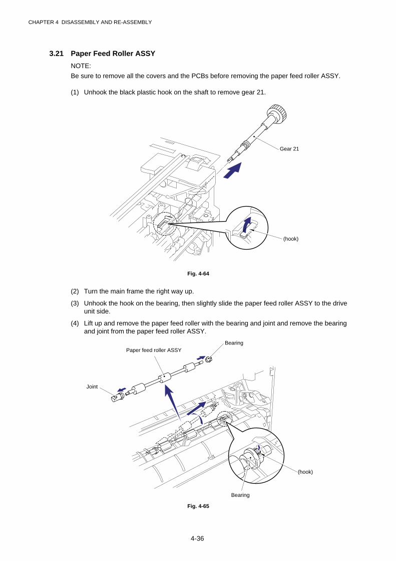
CHAPTER 4 DISASSEMBLY AND RE-ASSEMBLY
4-36
3.21 Paper Feed Roller ASSY
NOTE:
Be sure to remove all the covers and the PCBs before removing the paper feed roller ASSY.
(1) Unhook the black plastic hook on the shaft to remove gear 21.
Fig. 4-64
(2) Turn the main frame the right way up.
(3) Unhook the hook on the bearing, then slightly slide the paper feed roller ASSY to the driveunit side.
(4) Lift up and remove the paper feed roller with the bearing and joint and remove the bearingand joint from the paper feed roller ASSY.
Fig. 4-65
Gear 21
(hook)
(hook)
BearingPaper feed roller ASSY
Joint
Bearing

CHAPTER 4 DISASSEMBLY AND RE-ASSEMBLY
4-37
4. PACKING
Fig. 4-66
Insertion sheet
AC Cord
Accessory bag
Pad
Accessory carton
Drum Unit(with Toner Cartridge included)
Pad
Printer
Carton

CHAPTER 4 DISASSEMBLY AND RE-ASSEMBLY
4-38
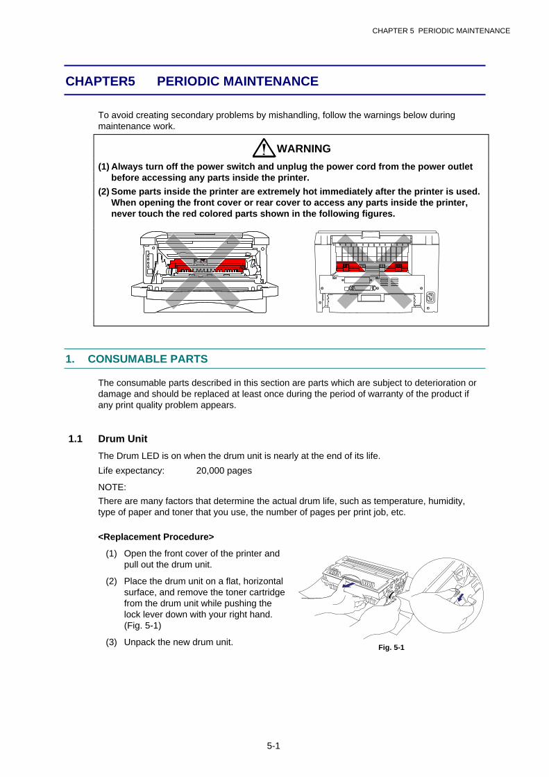
CHAPTER 5 PERIODIC MAINTENANCE
5-1
CHAPTER 5 PERIODIC MAINTENANCE
To avoid creating secondary problems by mishandling, follow the warnings below duringmaintenance work.
WARNING
(1) Always turn off the power switch and unplug the power cord from the power outletbefore accessing any parts inside the printer.
(2) Some parts inside the printer are extremely hot immediately after the printer is used.When opening the front cover or rear cover to access any parts inside the printer,never touch the red colored parts shown in the following figures.
1. CONSUMABLE PARTS
The consumable parts described in this section are parts which are subject to deterioration ordamage and should be replaced at least once during the period of warranty of the product ifany print quality problem appears.
1.1 Drum Unit
The Drum LED is on when the drum unit is nearly at the end of its life.
Life expectancy: 20,000 pages
NOTE:
There are many factors that determine the actual drum life, such as temperature, humidity,type of paper and toner that you use, the number of pages per print job, etc.
<Replacement Procedure>
(1) Open the front cover of the printer andpull out the drum unit.
(2) Place the drum unit on a flat, horizontalsurface, and remove the toner cartridgefrom the drum unit while pushing thelock lever down with your right hand.(Fig. 5-1)
(3) Unpack the new drum unit.Fig. 5-1
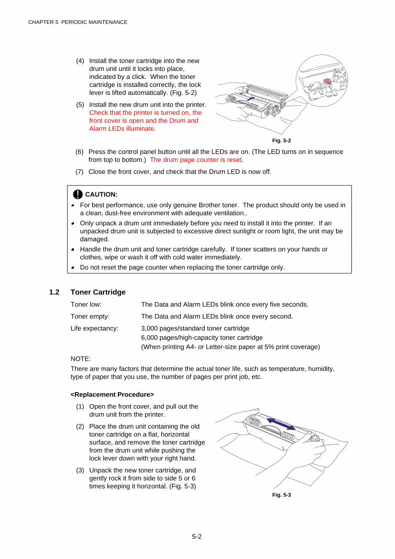
CHAPTER 5 PERIODIC MAINTENANCE
5-2
(4) Install the toner cartridge into the newdrum unit until it locks into place,indicated by a click. When the tonercartridge is installed correctly, the locklever is lifted automatically. (Fig. 5-2)
(5) Install the new drum unit into the printer.Check that the printer is turned on, thefront cover is open and the Drum andAlarm LEDs illuminate.
Fig. 5-2
(6) Press the control panel button until all the LEDs are on. (The LED turns on in sequencefrom top to bottom.) The drum page counter is reset.
(7) Close the front cover, and check that the Drum LED is now off.
! CAUTION:
� For best performance, use only genuine Brother toner. The product should only be used ina clean, dust-free environment with adequate ventilation..
� Only unpack a drum unit immediately before you need to install it into the printer. If anunpacked drum unit is subjected to excessive direct sunlight or room light, the unit may bedamaged.
� Handle the drum unit and toner cartridge carefully. If toner scatters on your hands orclothes, wipe or wash it off with cold water immediately.
� Do not reset the page counter when replacing the toner cartridge only.
1.2 Toner Cartridge
Toner low: The Data and Alarm LEDs blink once every five seconds.
Toner empty: The Data and Alarm LEDs blink once every second.
Life expectancy: 3,000 pages/standard toner cartridge6,000 pages/high-capacity toner cartridge(When printing A4- or Letter-size paper at 5% print coverage)
NOTE:
There are many factors that determine the actual toner life, such as temperature, humidity,type of paper that you use, the number of pages per print job, etc.
<Replacement Procedure>
(1) Open the front cover, and pull out thedrum unit from the printer.
(2) Place the drum unit containing the oldtoner cartridge on a flat, horizontalsurface, and remove the toner cartridgefrom the drum unit while pushing thelock lever down with your right hand.
(3) Unpack the new toner cartridge, andgently rock it from side to side 5 or 6times keeping it horizontal. (Fig. 5-3)
Fig. 5-3
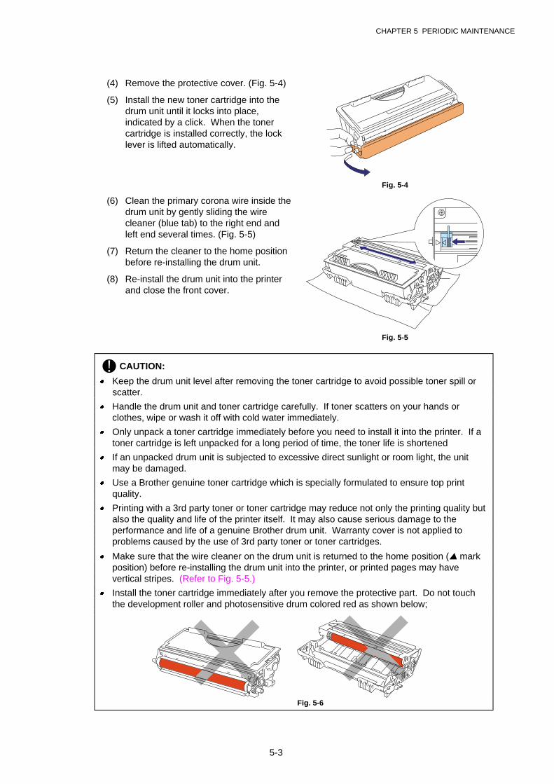
CHAPTER 5 PERIODIC MAINTENANCE
5-3
(4) Remove the protective cover. (Fig. 5-4)
(5) Install the new toner cartridge into thedrum unit until it locks into place,indicated by a click. When the tonercartridge is installed correctly, the locklever is lifted automatically.
Fig. 5-4
(6) Clean the primary corona wire inside thedrum unit by gently sliding the wirecleaner (blue tab) to the right end andleft end several times. (Fig. 5-5)
(7) Return the cleaner to the home positionbefore re-installing the drum unit.
(8) Re-install the drum unit into the printerand close the front cover.
Fig. 5-5
! CAUTION:
� Keep the drum unit level after removing the toner cartridge to avoid possible toner spill orscatter.
� Handle the drum unit and toner cartridge carefully. If toner scatters on your hands orclothes, wipe or wash it off with cold water immediately.
� Only unpack a toner cartridge immediately before you need to install it into the printer. If atoner cartridge is left unpacked for a long period of time, the toner life is shortened
� If an unpacked drum unit is subjected to excessive direct sunlight or room light, the unitmay be damaged.
� Use a Brother genuine toner cartridge which is specially formulated to ensure top printquality.
� Printing with a 3rd party toner or toner cartridge may reduce not only the printing quality butalso the quality and life of the printer itself. It may also cause serious damage to theperformance and life of a genuine Brother drum unit. Warranty cover is not applied toproblems caused by the use of 3rd party toner or toner cartridges.
� Make sure that the wire cleaner on the drum unit is returned to the home position (▲ markposition) before re-installing the drum unit into the printer, or printed pages may havevertical stripes. (Refer to Fig. 5-5.)
� Install the toner cartridge immediately after you remove the protective part. Do not touchthe development roller and photosensitive drum colored red as shown below;
Fig. 5-6
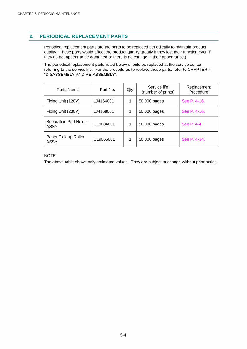
CHAPTER 5 PERIODIC MAINTENANCE
5-4
2. PERIODICAL REPLACEMENT PARTS
Periodical replacement parts are the parts to be replaced periodically to maintain productquality. These parts would affect the product quality greatly if they lost their function even ifthey do not appear to be damaged or there is no change in their appearance.)
The periodical replacement parts listed below should be replaced at the service centerreferring to the service life. For the procedures to replace these parts, refer to CHAPTER 4“DISASSEMBLY AND RE-ASSEMBLY”.
Parts Name Part No. QtyService life
(number of prints)Replacement
Procedure
Fixing Unit (120V) LJ4164001 1 50,000 pages See P. 4-16.
Fixing Unit (230V) LJ4168001 1 50,000 pages See P. 4-16.
Separation Pad HolderASSY
UL9084001 1 50,000 pages See P. 4-4.
Paper Pick-up RollerASSY
UL9066001 1 50,000 pages See P. 4-34.
NOTE:
The above table shows only estimated values. They are subject to change without prior notice.
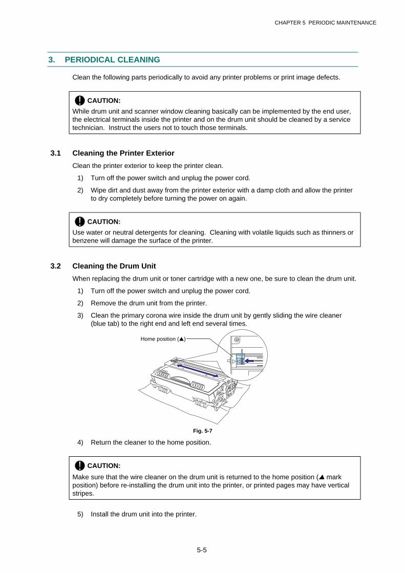
CHAPTER 5 PERIODIC MAINTENANCE
5-5
3. PERIODICAL CLEANING
Clean the following parts periodically to avoid any printer problems or print image defects.
! CAUTION:
While drum unit and scanner window cleaning basically can be implemented by the end user,the electrical terminals inside the printer and on the drum unit should be cleaned by a servicetechnician. Instruct the users not to touch those terminals.
3.1 Cleaning the Printer Exterior
Clean the printer exterior to keep the printer clean.
1) Turn off the power switch and unplug the power cord.
2) Wipe dirt and dust away from the printer exterior with a damp cloth and allow the printerto dry completely before turning the power on again.
! CAUTION:
Use water or neutral detergents for cleaning. Cleaning with volatile liquids such as thinners orbenzene will damage the surface of the printer.
3.2 Cleaning the Drum Unit
When replacing the drum unit or toner cartridge with a new one, be sure to clean the drum unit.
1) Turn off the power switch and unplug the power cord.
2) Remove the drum unit from the printer.
3) Clean the primary corona wire inside the drum unit by gently sliding the wire cleaner(blue tab) to the right end and left end several times.
Fig. 5-7
4) Return the cleaner to the home position.
! CAUTION:
Make sure that the wire cleaner on the drum unit is returned to the home position (▲ markposition) before re-installing the drum unit into the printer, or printed pages may have verticalstripes.
5) Install the drum unit into the printer.
Home position (▲)
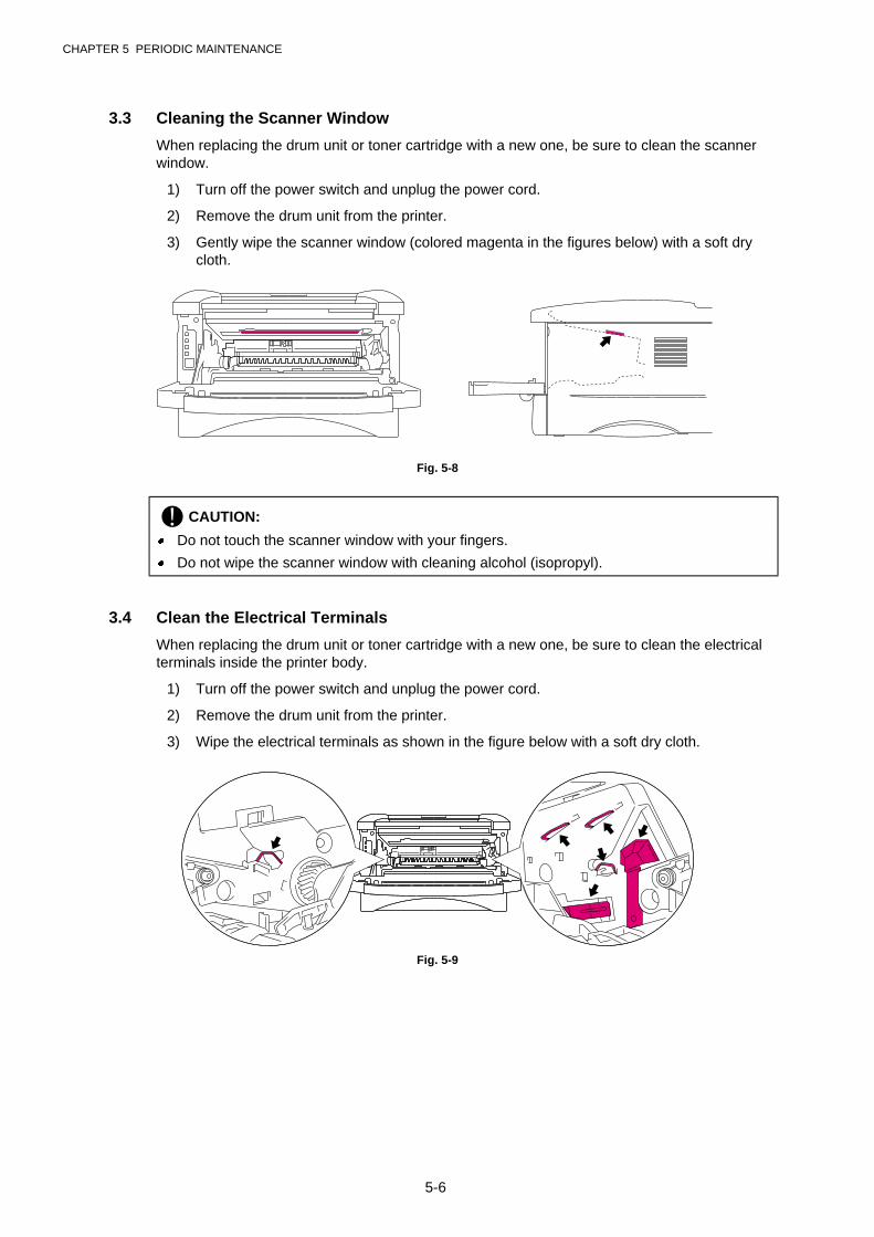
CHAPTER 5 PERIODIC MAINTENANCE
5-6
3.3 Cleaning the Scanner Window
When replacing the drum unit or toner cartridge with a new one, be sure to clean the scannerwindow.
1) Turn off the power switch and unplug the power cord.
2) Remove the drum unit from the printer.
3) Gently wipe the scanner window (colored magenta in the figures below) with a soft drycloth.
Fig. 5-8
! CAUTION:
� Do not touch the scanner window with your fingers.
� Do not wipe the scanner window with cleaning alcohol (isopropyl).
3.4 Clean the Electrical Terminals
When replacing the drum unit or toner cartridge with a new one, be sure to clean the electricalterminals inside the printer body.
1) Turn off the power switch and unplug the power cord.
2) Remove the drum unit from the printer.
3) Wipe the electrical terminals as shown in the figure below with a soft dry cloth.
Fig. 5-9

CHAPTER 5 PERIODIC MAINTENANCE
5-7
4. MTBF / MTTR
The meantime between failure (MTBF) and the meantime to repair (MTTR) for this printer areas follows;
MTBF: Up to 4,000 hours
MTTR: Average 30 minutes

CHAPTER 5 PERIODIC MAINTENANCE
5-8
CHAPTER 6 TROUBLESHOOTING
6-1
CHAPTER 6 TROUBLESHOOTING
1. INTRODUCTION
1.1 Initial Check
(1) Operating environment
Check if :
· The source voltage stays within ±10% from the rated voltage shown on the rating plate.
· The printer is installed on a solid, level surface.
· The room temperature is maintained between 10°C and 32.5°C. The relative humidity ismaintained between 20% and 80%.
· The printer is not located in a dusty place.
· The printer is not exposed to ammonia fumes or other harmful gases.
· The printer is not located in a hot or humid area (such as near water or a humidifier).
· The printer is not exposed to direct sunlight.
· The room is well-ventilated.
· The printer is not placed where the ventilation hole of the printer is blocked.
(2) Print paper
Check if :
· A recommended type of print paper is being used. [If the paper is too thick or too thin,or tends to curl, paper jams or paper feed problems may occur, or printed images maybe blurred.]
· The print paper is damped. [If so, use fresh paper, and check whether the print qualityimproves or not.]
· The print paper is short-grained paper or acid paper. [If so, print quality problems mayoccur.]
For further information on paper, refer to subsection 3.4 ‘Paper’ in CHAPTER 1.
(3) Consumable parts
Check if :
· The Toner LED is not lit on the printer control panel when a toner cartridge is installed inthe printer. [If the LED is lit, replace the cartridge with a new one.]
For further information on consumable parts, refer to Section 1 ‘Consumable Parts’ inCHAPTER 5.
(4) Others
Condensation:
When the printer is moved from a cold room into a warm room in cold weather,condensation may occur inside the printer, causing various problems as listed below:
· Condensation on the optical surfaces such as the scanning mirror, lenses, the reflectionmirror and the protection glass may cause the print image to be light.
· If the photosensitive drum is cold, the electrical resistance of the photosensitive layer isincreased, making it impossible to obtain the correct contrast when printing.
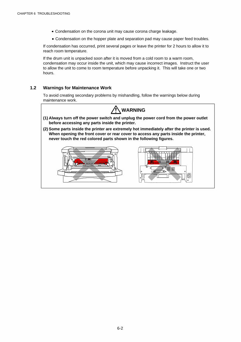
CHAPTER 6 TROUBLESHOOTING
6-2
· Condensation on the corona unit may cause corona charge leakage.
· Condensation on the hopper plate and separation pad may cause paper feed troubles.
If condensation has occurred, print several pages or leave the printer for 2 hours to allow it toreach room temperature.
If the drum unit is unpacked soon after it is moved from a cold room to a warm room,condensation may occur inside the unit, which may cause incorrect images. Instruct the userto allow the unit to come to room temperature before unpacking it. This will take one or twohours.
1.2 Warnings for Maintenance Work
To avoid creating secondary problems by mishandling, follow the warnings below duringmaintenance work.
WARNING
(1) Always turn off the power switch and unplug the power cord from the power outletbefore accessing any parts inside the printer.
(2) Some parts inside the printer are extremely hot immediately after the printer is used.When opening the front cover or rear cover to access any parts inside the printer,never touch the red colored parts shown in the following figures.
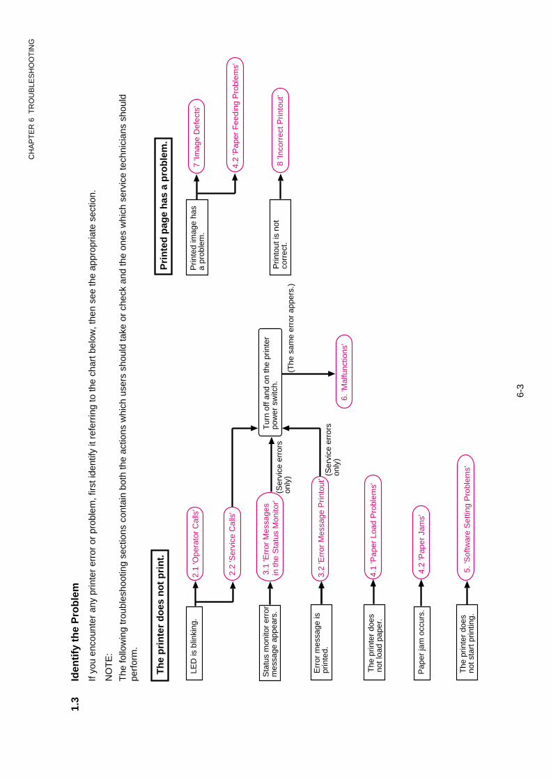
CH
AP
TE
R 6
TR
OU
BLE
SH
OO
TIN
G
6-3
1.3
Iden
tify
th
e P
rob
lem
If yo
u en
coun
ter
any
prin
ter
erro
r or
pro
blem
, firs
t ide
ntify
it r
efer
ring
to th
e ch
art b
elow
, the
n se
e th
e ap
prop
riate
sec
tion.
NO
TE
:
The
follo
win
g tr
oubl
esho
otin
g se
ctio
ns c
onta
in b
oth
the
actio
ns w
hich
use
rs s
houl
d ta
ke o
r ch
eck
and
the
ones
whi
ch s
ervi
ce te
chni
cian
s sh
ould
perf
orm
.
LED
is b
linki
ng.
Th
e p
rin
ter
do
es n
ot
pri
nt.
The
prin
ter
does
not s
tart
prin
ting.
3.2
'Err
or M
essa
ge P
rinto
ut'
4.1
'Pap
er L
oad
Pro
blem
s'
4.2
'Pap
er J
ams'
5. 'S
oftw
are
Set
ting
Pro
blem
s'
Sta
tus
mon
itor
erro
rm
essa
ge a
ppea
rs.
Pap
er ja
m o
ccur
s.
Prin
ted
imag
e ha
sa
prob
lem
.7
'Imag
e D
efec
ts'
4.2
'Pap
er F
eedi
ng P
robl
ems'
Prin
tout
is n
otco
rrec
t.8
'Inco
rrec
t Prin
tout
'
Pri
nte
d p
age
has
a p
rob
lem
.
2.1
'Ope
rato
r C
alls
'
2.2
'Ser
vice
Cal
ls'
6. 'M
alfu
nctio
ns'
3.1
'Err
or M
essa
ges
in th
e S
tatu
s M
onito
r'
Err
or m
essa
ge is
prin
ted.
The
prin
ter
does
not l
oad
pape
r.
Tur
n of
f and
on
the
prin
ter
pow
er s
witc
h.
(The
sam
e er
ror
appe
rs.)
(Ser
vice
err
ors
only
)
(Ser
vice
err
ors
only
)
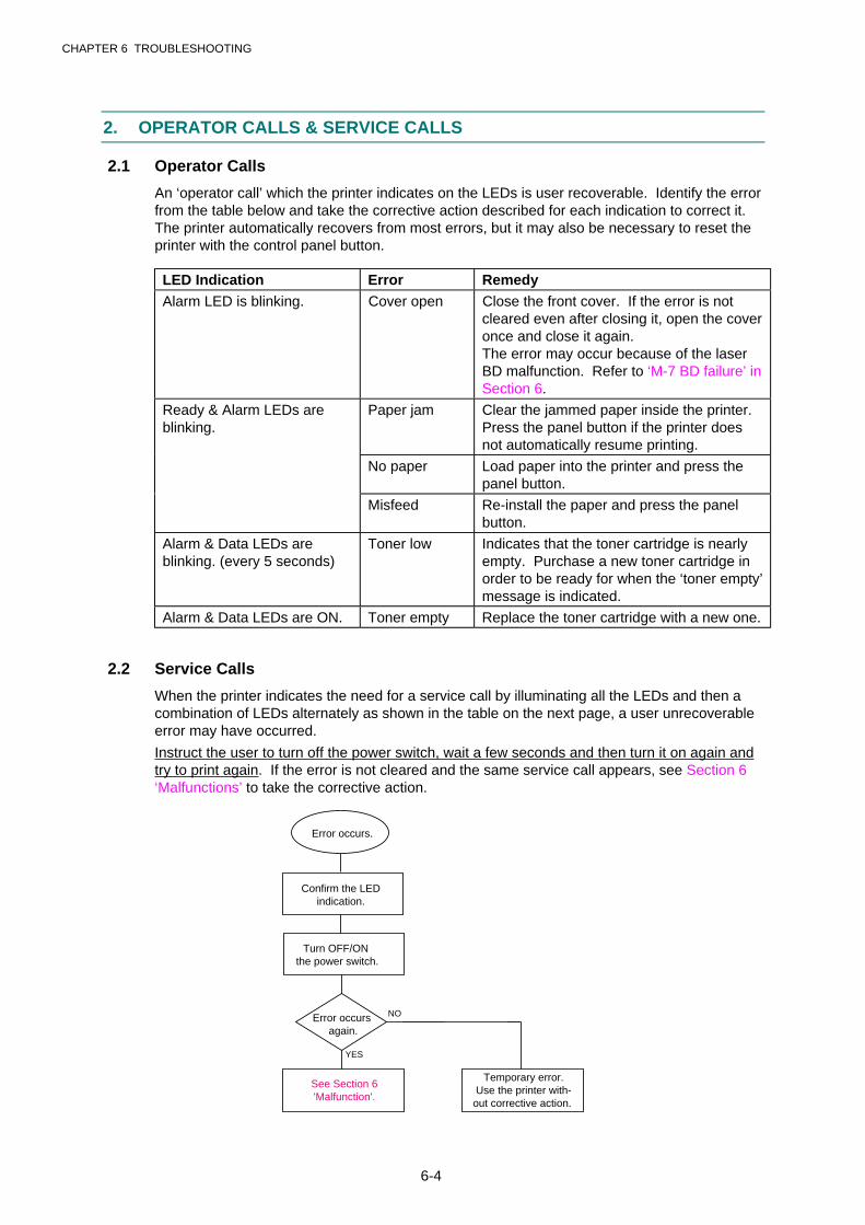
CHAPTER 6 TROUBLESHOOTING
6-4
2. OPERATOR CALLS & SERVICE CALLS
2.1 Operator Calls
An ‘operator call’ which the printer indicates on the LEDs is user recoverable. Identify the errorfrom the table below and take the corrective action described for each indication to correct it.The printer automatically recovers from most errors, but it may also be necessary to reset theprinter with the control panel button.
LED Indication Error RemedyAlarm LED is blinking. Cover open Close the front cover. If the error is not
cleared even after closing it, open the coveronce and close it again.The error may occur because of the laserBD malfunction. Refer to ‘M-7 BD failure’ inSection 6.
Ready & Alarm LEDs areblinking.
Paper jam Clear the jammed paper inside the printer.Press the panel button if the printer doesnot automatically resume printing.
No paper Load paper into the printer and press thepanel button.
Misfeed Re-install the paper and press the panelbutton.
Alarm & Data LEDs areblinking. (every 5 seconds)
Toner low Indicates that the toner cartridge is nearlyempty. Purchase a new toner cartridge inorder to be ready for when the ‘toner empty’message is indicated.
Alarm & Data LEDs are ON. Toner empty Replace the toner cartridge with a new one.
2.2 Service Calls
When the printer indicates the need for a service call by illuminating all the LEDs and then acombination of LEDs alternately as shown in the table on the next page, a user unrecoverableerror may have occurred.
Instruct the user to turn off the power switch, wait a few seconds and then turn it on again andtry to print again. If the error is not cleared and the same service call appears, see Section 6‘Malfunctions’ to take the corrective action.
Error occurs.
Confirm the LEDindication.
Turn OFF/ON the power switch.
Error occurs again.
See Section 6 'Malfunction'.
Temporary error.Use the printer with-
out corrective action.
NO
YES
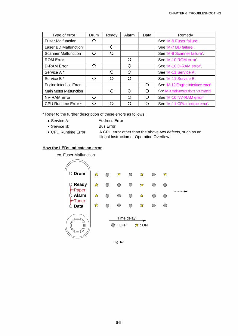
CHAPTER 6 TROUBLESHOOTING
6-5
Type of error Drum Ready Alarm Data Remedy
Fuser Malfunction � See ‘M-9 Fuser failure‘.
Laser BD Malfunction � See ‘M-7 BD failure’.
Scanner Malfunction � � See ‘M-8 Scanner failure’.
ROM Error � See ‘M-10 ROM error’.
D-RAM Error � � See ‘M-10 D-RAM error’.
Service A * � � See ‘M-11 Service A’.
Service B * � � � See ‘M-11 Service B’.
Engine Interface Error � See ‘M-12 Engine interface error’.
Main Motor Malfunction � � � See ‘M-3 Main motor does not rotated’.
NV-RAM Error � � � See ‘M-10 NV-RAM error’.
CPU Runtime Error * � � � � See ‘M-11 CPU runtime error’.
* Refer to the further description of these errors as follows;
· Service A: Address Error
· Service B: Bus Error
· CPU Runtime Error: A CPU error other than the above two defects, such as anIllegal Instruction or Operation Overflow
How the LEDs indicate an error
Time delay
: OFF : ON
Drum
Ready
AlarmPaper
TonerData
Fig. 6-1
ex. Fuser Malfunction
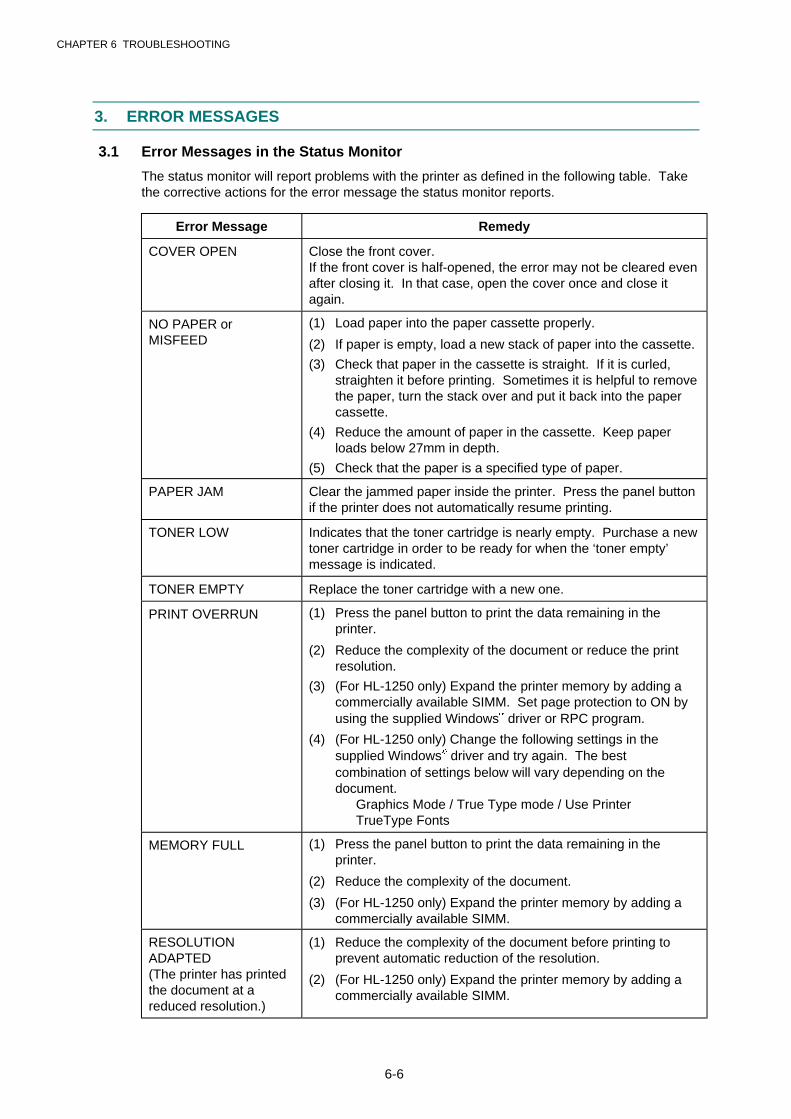
CHAPTER 6 TROUBLESHOOTING
6-6
3. ERROR MESSAGES
3.1 Error Messages in the Status Monitor
The status monitor will report problems with the printer as defined in the following table. Takethe corrective actions for the error message the status monitor reports.
Error Message Remedy
COVER OPEN Close the front cover.If the front cover is half-opened, the error may not be cleared evenafter closing it. In that case, open the cover once and close itagain.
NO PAPER orMISFEED
(1) Load paper into the paper cassette properly.
(2) If paper is empty, load a new stack of paper into the cassette.
(3) Check that paper in the cassette is straight. If it is curled,straighten it before printing. Sometimes it is helpful to removethe paper, turn the stack over and put it back into the papercassette.
(4) Reduce the amount of paper in the cassette. Keep paperloads below 27mm in depth.
(5) Check that the paper is a specified type of paper.
PAPER JAM Clear the jammed paper inside the printer. Press the panel buttonif the printer does not automatically resume printing.
TONER LOW Indicates that the toner cartridge is nearly empty. Purchase a newtoner cartridge in order to be ready for when the ‘toner empty’message is indicated.
TONER EMPTY Replace the toner cartridge with a new one.
PRINT OVERRUN (1) Press the panel button to print the data remaining in theprinter.
(2) Reduce the complexity of the document or reduce the printresolution.
(3) (For HL-1250 only) Expand the printer memory by adding acommercially available SIMM. Set page protection to ON byusing the supplied Windowsâ driver or RPC program.
(4) (For HL-1250 only) Change the following settings in thesupplied Windowsâ driver and try again. The bestcombination of settings below will vary depending on thedocument.
Graphics Mode / True Type mode / Use PrinterTrueType Fonts
MEMORY FULL (1) Press the panel button to print the data remaining in theprinter.
(2) Reduce the complexity of the document.
(3) (For HL-1250 only) Expand the printer memory by adding acommercially available SIMM.
RESOLUTIONADAPTED(The printer has printedthe document at areduced resolution.)
(1) Reduce the complexity of the document before printing toprevent automatic reduction of the resolution.
(2) (For HL-1250 only) Expand the printer memory by adding acommercially available SIMM.

CHAPTER 6 TROUBLESHOOTING
6-7
Error Message Remedy
FUSER MALFUNCTION Turn the power switch off, wait a few seconds and then turn it onagain. Leave the printer for 10 minutes with power on.
If the same error occurs again, see ‘M-9 Fuser failure’.
LASER BDMALFUNCTION
Turn the power switch off, wait a few seconds and then turn it onagain.
If the same error occurs again, see ‘M-7 BD failure’.
SCANNERMALFUNCTION
Turn the power switch off, wait a few seconds and then turn it onagain.
If the same error occurs again, see ‘M-8 Scanner failure’.
D-RAM ERROR Turn the power switch off, wait a few seconds and then turn it onagain.
If the same error occurs again, see ‘M-10 ROM error / D-RAMerror / NV-RAM error’.
NV-RAM ERROR Turn the power switch off, wait a few seconds and then turn it onagain.
If the same error occurs again, see ‘M-10 ROM error / D-RAMerror / NV-RAM error’
MAIN MOTOR ERROR Turn the power switch off, wait a few seconds and then turn it onagain.
If the same error occurs again, see ‘M-3 Main motor does notrotate’.
ENGINE INTERFACEERROR
Turn the power switch off, wait a few seconds and then turn it onagain.
If the same error occurs again, see ‘M-12 Engine interface error’.
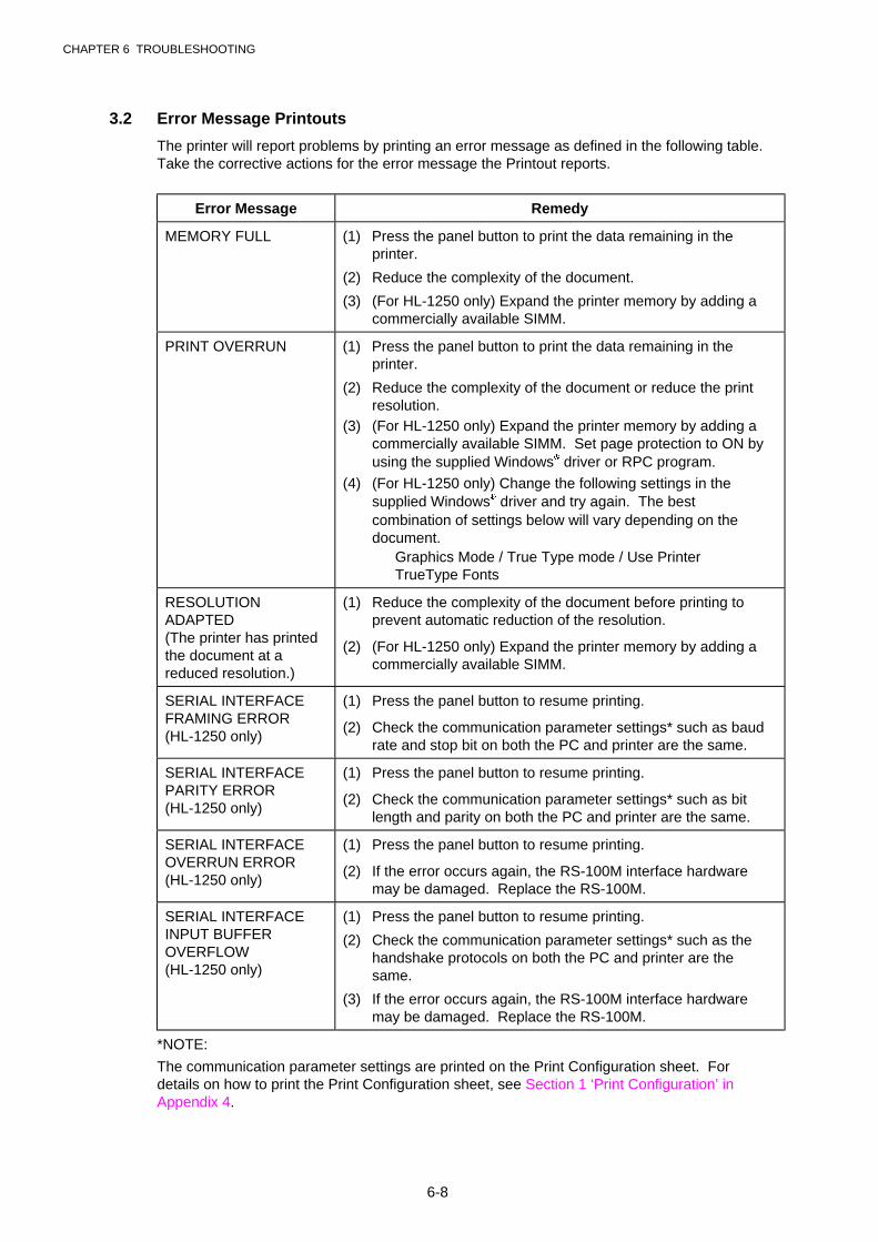
CHAPTER 6 TROUBLESHOOTING
6-8
3.2 Error Message Printouts
The printer will report problems by printing an error message as defined in the following table.Take the corrective actions for the error message the Printout reports.
Error Message Remedy
MEMORY FULL (1) Press the panel button to print the data remaining in theprinter.
(2) Reduce the complexity of the document.
(3) (For HL-1250 only) Expand the printer memory by adding acommercially available SIMM.
PRINT OVERRUN (1) Press the panel button to print the data remaining in theprinter.
(2) Reduce the complexity of the document or reduce the printresolution.
(3) (For HL-1250 only) Expand the printer memory by adding acommercially available SIMM. Set page protection to ON byusing the supplied Windowsâ driver or RPC program.
(4) (For HL-1250 only) Change the following settings in thesupplied Windowsâ driver and try again. The bestcombination of settings below will vary depending on thedocument.
Graphics Mode / True Type mode / Use PrinterTrueType Fonts
RESOLUTIONADAPTED(The printer has printedthe document at areduced resolution.)
(1) Reduce the complexity of the document before printing toprevent automatic reduction of the resolution.
(2) (For HL-1250 only) Expand the printer memory by adding acommercially available SIMM.
SERIAL INTERFACEFRAMING ERROR(HL-1250 only)
(1) Press the panel button to resume printing.
(2) Check the communication parameter settings* such as baudrate and stop bit on both the PC and printer are the same.
SERIAL INTERFACEPARITY ERROR(HL-1250 only)
(1) Press the panel button to resume printing.
(2) Check the communication parameter settings* such as bitlength and parity on both the PC and printer are the same.
SERIAL INTERFACEOVERRUN ERROR(HL-1250 only)
(1) Press the panel button to resume printing.
(2) If the error occurs again, the RS-100M interface hardwaremay be damaged. Replace the RS-100M.
SERIAL INTERFACEINPUT BUFFEROVERFLOW(HL-1250 only)
(1) Press the panel button to resume printing.
(2) Check the communication parameter settings* such as thehandshake protocols on both the PC and printer are thesame.
(3) If the error occurs again, the RS-100M interface hardwaremay be damaged. Replace the RS-100M.
*NOTE:
The communication parameter settings are printed on the Print Configuration sheet. Fordetails on how to print the Print Configuration sheet, see Section 1 ‘Print Configuration’ inAppendix 4.
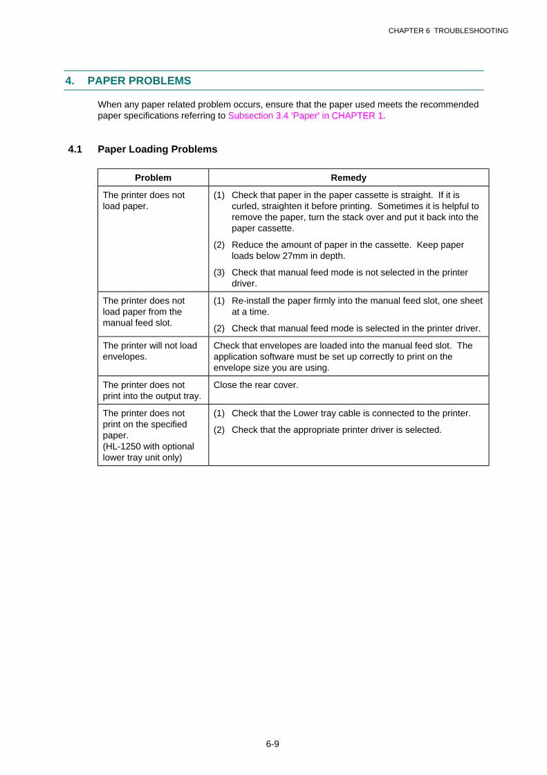
CHAPTER 6 TROUBLESHOOTING
6-9
4. PAPER PROBLEMS
When any paper related problem occurs, ensure that the paper used meets the recommendedpaper specifications referring to Subsection 3.4 ‘Paper’ in CHAPTER 1.
4.1 Paper Loading Problems
Problem Remedy
The printer does notload paper.
(1) Check that paper in the paper cassette is straight. If it iscurled, straighten it before printing. Sometimes it is helpful toremove the paper, turn the stack over and put it back into thepaper cassette.
(2) Reduce the amount of paper in the cassette. Keep paperloads below 27mm in depth.
(3) Check that manual feed mode is not selected in the printerdriver.
The printer does notload paper from themanual feed slot.
(1) Re-install the paper firmly into the manual feed slot, one sheetat a time.
(2) Check that manual feed mode is selected in the printer driver.
The printer will not loadenvelopes.
Check that envelopes are loaded into the manual feed slot. Theapplication software must be set up correctly to print on theenvelope size you are using.
The printer does notprint into the output tray.
Close the rear cover.
The printer does notprint on the specifiedpaper.(HL-1250 with optionallower tray unit only)
(1) Check that the Lower tray cable is connected to the printer.
(2) Check that the appropriate printer driver is selected.
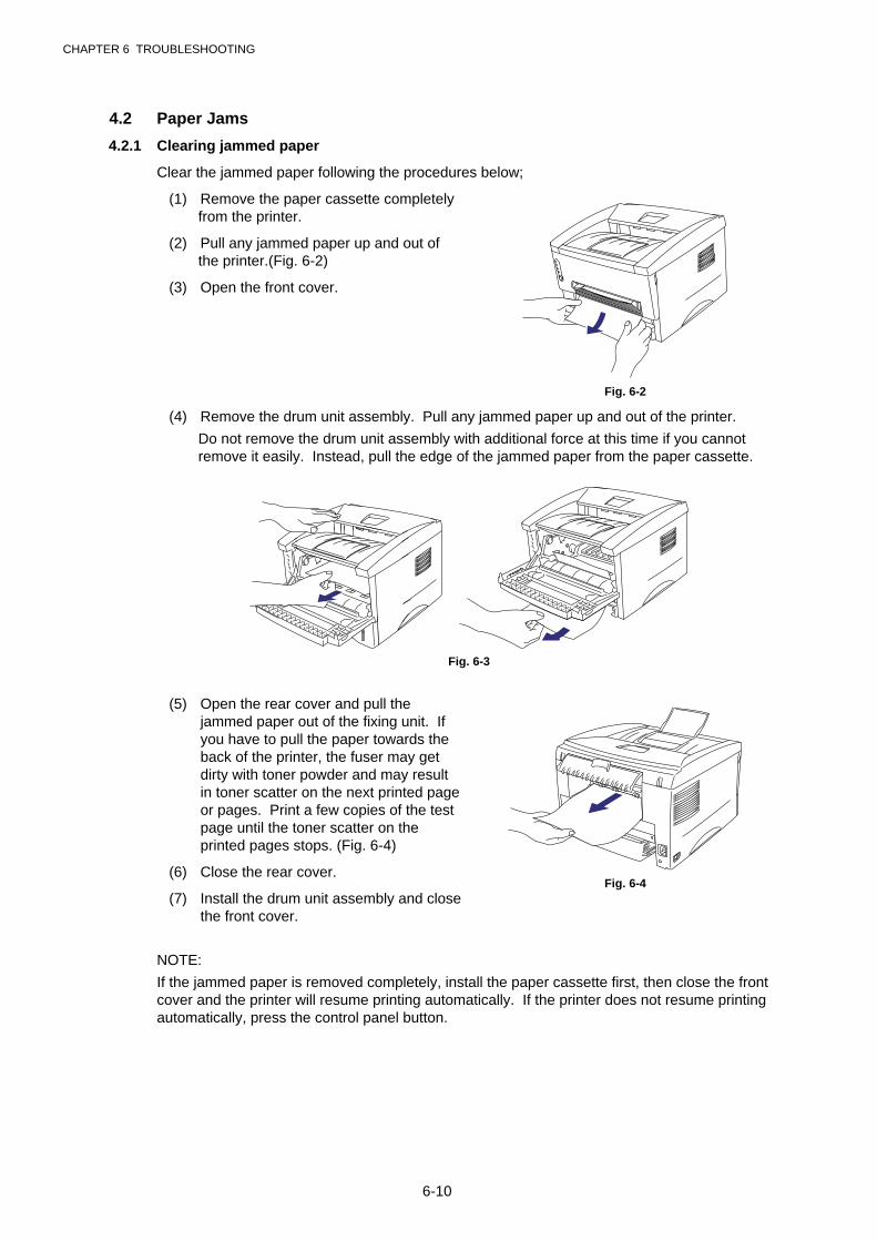
CHAPTER 6 TROUBLESHOOTING
6-10
4.2 Paper Jams
4.2.1 Clearing jammed paper
Clear the jammed paper following the procedures below;
(1) Remove the paper cassette completelyfrom the printer.
(2) Pull any jammed paper up and out ofthe printer.(Fig. 6-2)
(3) Open the front cover.
Fig. 6-2
(4) Remove the drum unit assembly. Pull any jammed paper up and out of the printer.
Do not remove the drum unit assembly with additional force at this time if you cannotremove it easily. Instead, pull the edge of the jammed paper from the paper cassette.
Fig. 6-3
(5) Open the rear cover and pull thejammed paper out of the fixing unit. Ifyou have to pull the paper towards theback of the printer, the fuser may getdirty with toner powder and may resultin toner scatter on the next printed pageor pages. Print a few copies of the testpage until the toner scatter on theprinted pages stops. (Fig. 6-4)
(6) Close the rear cover.
(7) Install the drum unit assembly and closethe front cover.
Fig. 6-4
NOTE:
If the jammed paper is removed completely, install the paper cassette first, then close the frontcover and the printer will resume printing automatically. If the printer does not resume printingautomatically, press the control panel button.
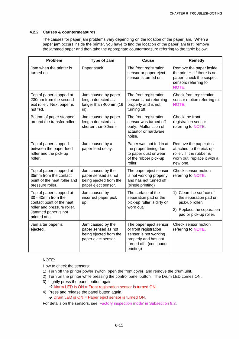
CHAPTER 6 TROUBLESHOOTING
6-11
4.2.2 Causes & countermeasures
The causes for paper jam problems vary depending on the location of the paper jam. When apaper jam occurs inside the printer, you have to find the location of the paper jam first, removethe jammed paper and then take the appropriate countermeasure referring to the table below;
Problem Type of Jam Cause Remedy
Jam when the printer isturned on.
Paper stuck The front registrationsensor or paper ejectsensor is turned on.
Remove the paper insidethe printer. If there is nopaper, check the suspectsensors referring toNOTE.
Top of paper stopped at230mm from the secondexit roller. Next paper isnot fed.
Jam caused by paperlength detected aslonger than 400mm (16in).
The front registrationsensor is not returningproperly and is notturning off.
Check front registrationsensor motion referring toNOTE.
Bottom of paper stoppedaround the transfer roller.
Jam caused by paperlength detected asshorter than 80mm.
The front registrationsensor was turned offearly. Malfunction ofactuator or hardwarenoise.
Check the frontregistration sensorreferring to NOTE.
Top of paper stoppedbetween the paper feedroller and the pick-uproller.
Jam caused by apaper feed delay.
Paper was not fed in atthe proper timing dueto paper dust or wearof the rubber pick-uproller.
Remove the paper dustattached to the pick-uproller. If the rubber isworn out, replace it with anew one.
Top of paper stopped at35mm from the contactpoint of the heat roller andpressure roller.
Jam caused by thepaper sensed as notbeing ejected from thepaper eject sensor.
The paper eject sensoris not working properlyand has not turned off.(single printing)
Check sensor motionreferring to NOTE.
Top of paper stopped at30 - 40mm from thecontact point of the heatroller and pressure roller.Jammed paper is notprinted at all.
Jam caused byincorrect paper pickup.
The surface of theseparation pad or thepick-up roller is dirty orworn out.
1) Clean the surface ofthe separation pad orpick-up roller.
2) Replace the separationpad or pick-up roller.
Jam after paper isejected.
Jam caused by thepaper sensed as notbeing ejected from thepaper eject sensor.
The paper eject sensoror front registrationsensor is not workingproperly and has notturned off. (continuousprinting)
Check sensor motionreferring to NOTE.
NOTE:
How to check the sensors:1) Turn off the printer power switch, open the front cover, and remove the drum unit.2) Turn on the printer while pressing the control panel button. The Drum LED comes ON.3) Lightly press the panel button again. � Alarm LED is ON = Front registration sensor is turned ON.4) Press and release the panel button again.� Drum LED is ON = Paper eject sensor is turned ON.
For details on the sensors, see ‘Factory inspection mode’ in Subsection 9.2.
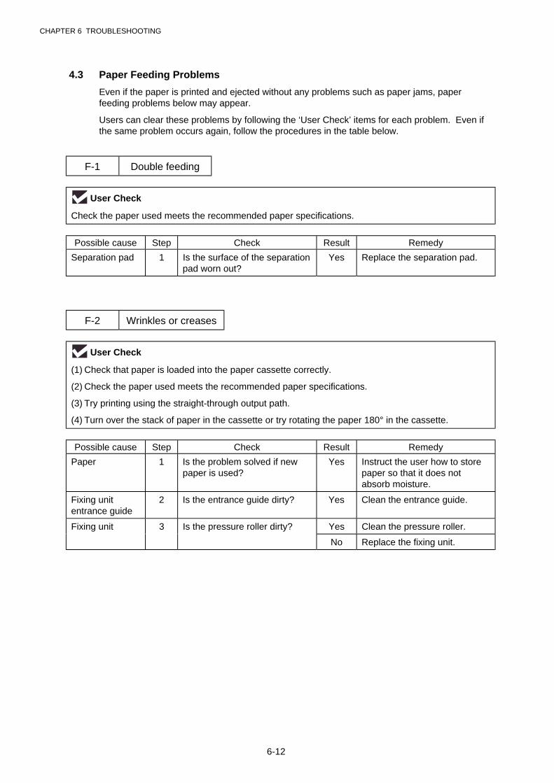
CHAPTER 6 TROUBLESHOOTING
6-12
4.3 Paper Feeding Problems
Even if the paper is printed and ejected without any problems such as paper jams, paperfeeding problems below may appear.
Users can clear these problems by following the ‘User Check’ items for each problem. Even ifthe same problem occurs again, follow the procedures in the table below.
F-1 Double feeding
User Check
Check the paper used meets the recommended paper specifications.
Possible cause Step Check Result Remedy
Separation pad 1 Is the surface of the separationpad worn out?
Yes Replace the separation pad.
F-2 Wrinkles or creases
User Check
(1) Check that paper is loaded into the paper cassette correctly.
(2) Check the paper used meets the recommended paper specifications.
(3) Try printing using the straight-through output path.
(4) Turn over the stack of paper in the cassette or try rotating the paper 180° in the cassette.
Possible cause Step Check Result Remedy
Paper 1 Is the problem solved if newpaper is used?
Yes Instruct the user how to storepaper so that it does notabsorb moisture.
Fixing unitentrance guide
2 Is the entrance guide dirty? Yes Clean the entrance guide.
Fixing unit 3 Is the pressure roller dirty? Yes Clean the pressure roller.
No Replace the fixing unit.
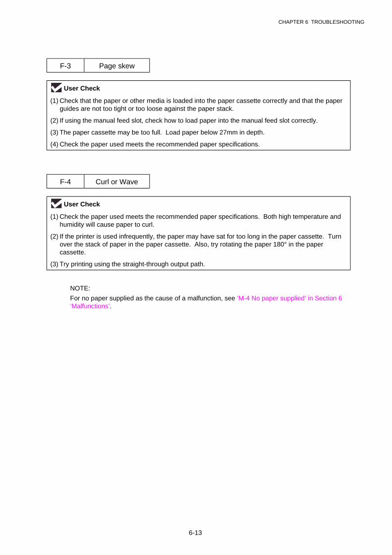
CHAPTER 6 TROUBLESHOOTING
6-13
F-3 Page skew
User Check
(1) Check that the paper or other media is loaded into the paper cassette correctly and that the paperguides are not too tight or too loose against the paper stack.
(2) If using the manual feed slot, check how to load paper into the manual feed slot correctly.
(3) The paper cassette may be too full. Load paper below 27mm in depth.
(4) Check the paper used meets the recommended paper specifications.
F-4 Curl or Wave
User Check
(1) Check the paper used meets the recommended paper specifications. Both high temperature andhumidity will cause paper to curl.
(2) If the printer is used infrequently, the paper may have sat for too long in the paper cassette. Turnover the stack of paper in the paper cassette. Also, try rotating the paper 180° in the papercassette.
(3) Try printing using the straight-through output path.
NOTE:
For no paper supplied as the cause of a malfunction, see ‘M-4 No paper supplied’ in Section 6‘Malfunctions’.
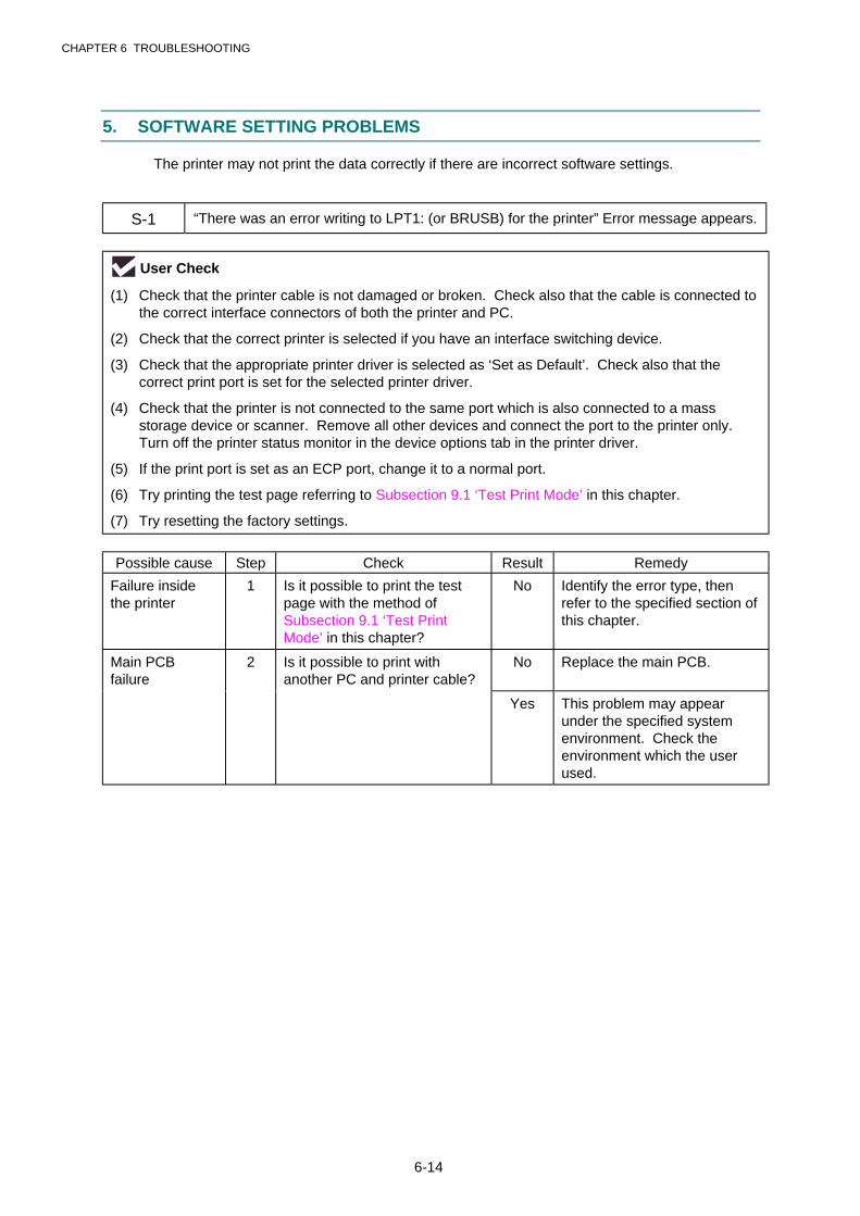
CHAPTER 6 TROUBLESHOOTING
6-14
5. SOFTWARE SETTING PROBLEMS
The printer may not print the data correctly if there are incorrect software settings.
S-1 “There was an error writing to LPT1: (or BRUSB) for the printer” Error message appears.
User Check
(1) Check that the printer cable is not damaged or broken. Check also that the cable is connected tothe correct interface connectors of both the printer and PC.
(2) Check that the correct printer is selected if you have an interface switching device.
(3) Check that the appropriate printer driver is selected as ‘Set as Default’. Check also that thecorrect print port is set for the selected printer driver.
(4) Check that the printer is not connected to the same port which is also connected to a massstorage device or scanner. Remove all other devices and connect the port to the printer only.Turn off the printer status monitor in the device options tab in the printer driver.
(5) If the print port is set as an ECP port, change it to a normal port.
(6) Try printing the test page referring to Subsection 9.1 ‘Test Print Mode’ in this chapter.
(7) Try resetting the factory settings.
Possible cause Step Check Result Remedy
Failure insidethe printer
1 Is it possible to print the testpage with the method ofSubsection 9.1 ‘Test PrintMode’ in this chapter?
No Identify the error type, thenrefer to the specified section ofthis chapter.
Main PCBfailure
2 Is it possible to print withanother PC and printer cable?
No Replace the main PCB.
Yes This problem may appearunder the specified systemenvironment. Check theenvironment which the userused.

CHAPTER 6 TROUBLESHOOTING
6-15
S-2 Unable to print from application software with the serial interface. (HL-1250 only)
User Check
Check that the slide switch of the serial interface is in the correct position and the serial interfacesetting are correctly set up with the DIP switches.
Possible cause Step Check Result Remedy
Failure insidethe printer
1 Is it possible to print the testpage with the method ofSubsection 9.1 ‘Test PrintMode’ in this chapter?
No Identify the error type, thenrefer to the specified section ofthis chapter.
Main PCBfailure
2 Is it possible to print withanother PC, printer cable andRS-100M?
No Replace the main PCB.
RS-100M failure 3 Is it possible to print withanother PC and cable?
No Replace the RS-100M.
Yes This problem may appearunder the specified systemenvironment. Check theenvironment which the userused.
S-3 Unable to print from application software under DOS.
User Check
(1) Check that the DOS application software interface settings match that of your printer.
(2) Check if the printer has any printer alarms active.
(3) Check if the appropriate printer is selected in your application software.
(4) (HL-1250 only) If the serial interface is used, check that the RS-232C serial interface is selectedwith the slide switch. Check that the interface settings are correctly set up with the proper DIPswitches. Check that the serial parameters of baud rate, parity and stop bits match between yourapplication software and the printer.
Possible cause Step Check Result Remedy
Failure insidethe printer
1 Is it possible to print the testpage with the method ofSubsection 9.1 ‘Test PrintMode’ in this chapter?
No Identify the error type, thenrefer to the specified section ofthis chapter.
Main PCBfailure
2 Is it possible to print withanother PC and printer cable?
No Replace the main PCB.
Yes This problem may appearunder the specified systemenvironment. Check theenvironment which the userused.
NOTE:
If this problem appears when using the RS-100M, follow the procedures in “S-2” on this page.
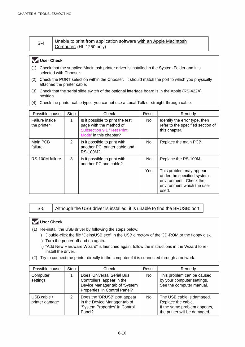
CHAPTER 6 TROUBLESHOOTING
6-16
S-4 Unable to print from application software with an Apple MacintoshComputer. (HL-1250 only)
User Check
(1) Check that the supplied Macintosh printer driver is installed in the System Folder and it isselected with Chooser.
(2) Check the PORT selection within the Chooser. It should match the port to which you physicallyattached the printer cable.
(3) Check that the serial slide switch of the optional interface board is in the Apple (RS-422A)position.
(4) Check the printer cable type: you cannot use a Local Talk or straight-through cable.
Possible cause Step Check Result Remedy
Failure insidethe printer
1 Is it possible to print the testpage with the method ofSubsection 9.1 ‘Test PrintMode’ in this chapter?
No Identify the error type, thenrefer to the specified section ofthis chapter.
Main PCBfailure
2 Is it possible to print withanother PC, printer cable andRS-100M?
No Replace the main PCB.
RS-100M failure 3 Is it possible to print withanother PC and cable?
No Replace the RS-100M.
Yes This problem may appearunder the specified systemenvironment. Check theenvironment which the userused.
S-5 Although the USB driver is installed, it is unable to find the BRUSB: port.
User Check
(1) Re-install the USB driver by following the steps below;i) Double-click the file “DeinsUSB.exe” in the USB directory of the CD-ROM or the floppy disk.ii) Turn the printer off and on again.iii) “Add New Hardware Wizard” is launched again, follow the instructions in the Wizard to re-
install the driver.
(2) Try to connect the printer directly to the computer if it is connected through a network.
Possible cause Step Check Result Remedy
Computersettings
1 Does ‘Universal Serial BusControllers’ appear in theDevice Manager tab of ‘SystemProperties’ in Control Panel?
No This problem can be causedby your computer settings.See the computer manual.
USB cable /printer damage
2 Does the ‘BRUSB’ port appearin the Device Manager tab of‘System Properties’ in ControlPanel?
No The USB cable is damaged.Replace the cable.If the same problem appears,the printer will be damaged.
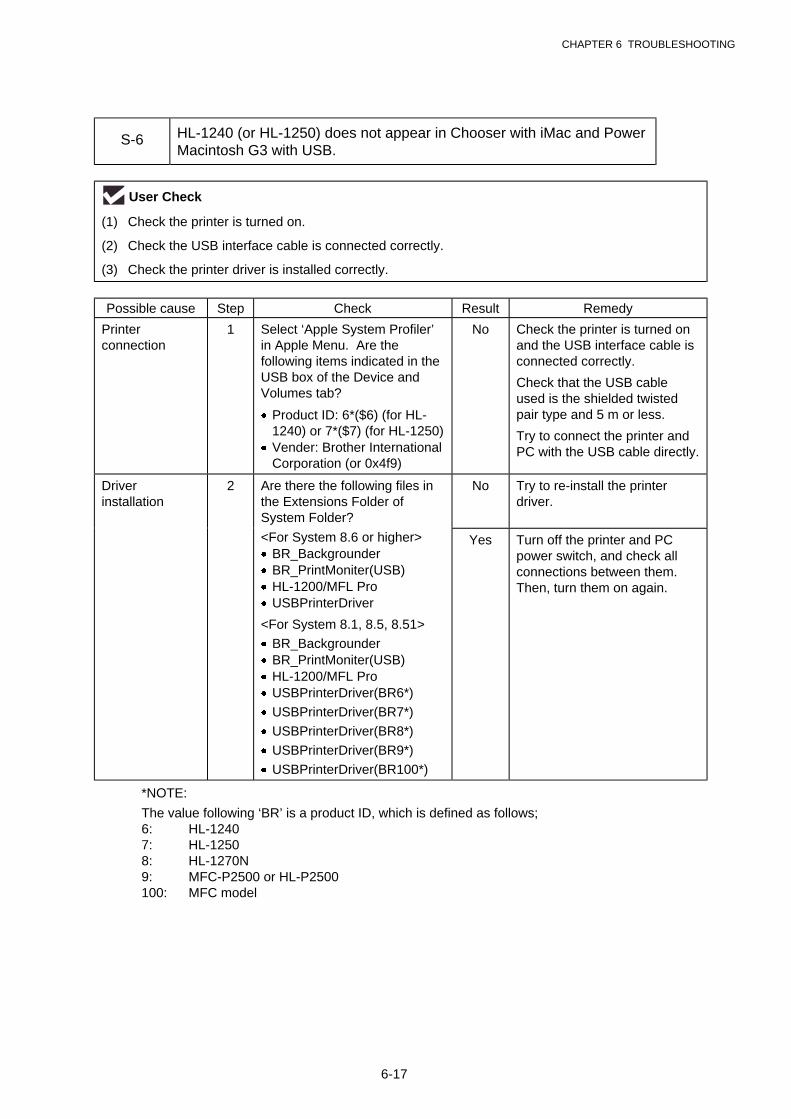
CHAPTER 6 TROUBLESHOOTING
6-17
S-6 HL-1240 (or HL-1250) does not appear in Chooser with iMac and PowerMacintosh G3 with USB.
User Check
(1) Check the printer is turned on.
(2) Check the USB interface cable is connected correctly.
(3) Check the printer driver is installed correctly.
Possible cause Step Check Result Remedy
Printerconnection
1 Select ‘Apple System Profiler’in Apple Menu. Are thefollowing items indicated in theUSB box of the Device andVolumes tab?
· Product ID: 6*($6) (for HL-1240) or 7*($7) (for HL-1250)
· Vender: Brother InternationalCorporation (or 0x4f9)
No Check the printer is turned onand the USB interface cable isconnected correctly.
Check that the USB cableused is the shielded twistedpair type and 5 m or less.
Try to connect the printer andPC with the USB cable directly.
Driverinstallation
2 Are there the following files inthe Extensions Folder ofSystem Folder?
No Try to re-install the printerdriver.
<For System 8.6 or higher>· BR_Backgrounder· BR_PrintMoniter(USB)· HL-1200/MFL Pro· USBPrinterDriver
<For System 8.1, 8.5, 8.51>
· BR_Backgrounder· BR_PrintMoniter(USB)· HL-1200/MFL Pro· USBPrinterDriver(BR6*)
· USBPrinterDriver(BR7*)
· USBPrinterDriver(BR8*)
· USBPrinterDriver(BR9*)
· USBPrinterDriver(BR100*)
Yes Turn off the printer and PCpower switch, and check allconnections between them.Then, turn them on again.
*NOTE:
The value following ‘BR’ is a product ID, which is defined as follows;6: HL-12407: HL-12508: HL-1270N9: MFC-P2500 or HL-P2500100: MFC model
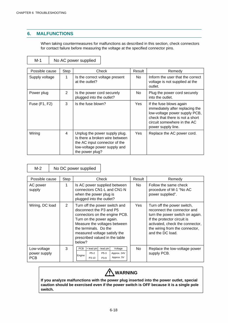
CHAPTER 6 TROUBLESHOOTING
6-18
6. MALFUNCTIONS
When taking countermeasures for malfunctions as described in this section, check connectorsfor contact failure before measuring the voltage at the specified connector pins.
M-1 No AC power supplied
Possible cause Step Check Result Remedy
Supply voltage 1 Is the correct voltage presentat the outlet?
No Inform the user that the correctvoltage is not supplied at theoutlet.
Power plug 2 Is the power cord securelyplugged into the outlet?
No Plug the power cord securelyinto the outlet.
Fuse (F1, F2) 3 Is the fuse blown? Yes If the fuse blows againimmediately after replacing thelow-voltage power supply PCB,check that there is not a shortcircuit somewhere in the ACpower supply line.
Wiring 4 Unplug the power supply plug.Is there a broken wire betweenthe AC input connector of thelow-voltage power supply andthe power plug?
Yes Replace the AC power cord.
M-2 No DC power supplied
Possible cause Step Check Result Remedy
AC powersupply
1 Is AC power supplied betweenconnectors CN1-L and CN1-Nwhen the power plug isplugged into the outlet?
No Follow the same checkprocedure of M-1 “No ACpower supplied”.
Wiring, DC load 2 Turn off the power switch anddisconnect the P3 and P5connectors on the engine PCB.Turn on the power again.Measure the voltages betweenthe terminals. Do themeasured voltage satisfy theprescribed valued in the tablebelow?
Yes Turn off the power switch,reconnect the connector andturn the power switch on again.If the protector circuit isactivated, check the connector,the wiring from the connector,and the DC load.
Low-voltagepower supplyPCB
3 PCB + lead pin - lead pin Voltage
EngineP5-2 P5-3 Approx. 24V
P3-10 P3-9 Approx. 5V
No Replace the low-voltage powersupply PCB.
WARNING
If you analyze malfunctions with the power plug inserted into the power outlet, specialcaution should be exercised even if the power switch is OFF because it is a single poleswitch.
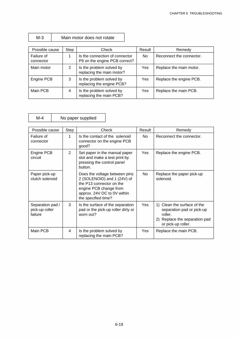
CHAPTER 6 TROUBLESHOOTING
6-19
M-3 Main motor does not rotate
Possible cause Step Check Result Remedy
Failure ofconnector
1 Is the connection of connectorP9 on the engine PCB correct?
No Reconnect the connector.
Main motor 2 Is the problem solved byreplacing the main motor?
Yes Replace the main motor.
Engine PCB 3 Is the problem solved byreplacing the engine PCB?
Yes Replace the engine PCB.
Main PCB 4 Is the problem solved byreplacing the main PCB?
Yes Replace the main PCB.
M-4 No paper supplied
Possible cause Step Check Result Remedy
Failure ofconnector
1 Is the contact of the solenoidconnector on the engine PCBgood?
No Reconnect the connector.
Engine PCBcircuit
2 Set paper in the manual paperslot and make a test print bypressing the control panelbutton.
Yes Replace the engine PCB.
Paper pick-upclutch solenoid
Does the voltage between pins2 (SOLENOID) and 1 (24V) ofthe P13 connector on theengine PCB change fromapprox. 24V DC to 0V withinthe specified time?
No Replace the paper pick-upsolenoid.
Separation pad /pick-up rollerfailure
3 Is the surface of the separationpad or the pick-up roller dirty orworn out?
Yes 1) Clean the surface of theseparation pad or pick-uproller.
2) Replace the separation pador pick-up roller.
Main PCB 4 Is the problem solved byreplacing the main PCB?
Yes Replace the main PCB.
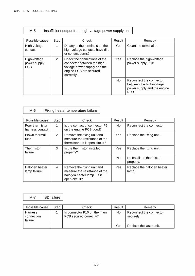
CHAPTER 6 TROUBLESHOOTING
6-20
M-5 Insufficient output from high-voltage power supply unit
Possible cause Step Check Result Remedy
High-voltagecontact
1 Do any of the terminals on thehigh-voltage contacts have dirtor contact burns?
Yes Clean the terminals.
High-voltagepower supplyPCB
2 Check the connections of theconnector between the high-voltage power supply and theengine PCB are securedcorrectly.
Yes Replace the high-voltagepower supply PCB
No Reconnect the connectorbetween the high-voltagepower supply and the enginePCB.
M-6 Fixing heater temperature failure
Possible cause Step Check Result Remedy
Poor thermistorharness contact
1 Is the contact of connector P6on the engine PCB good?
No Reconnect the connector.
Blown thermalfuse
2 Remove the fixing unit andmeasure the resistance of thethermistor. Is it open circuit?
Yes Replace the fixing unit.
Thermistorfailure
3 Is the thermistor installedproperly?
Yes Replace the fixing unit.
No Reinstall the thermistorproperly.
Halogen heaterlamp failure
4 Remove the fixing unit andmeasure the resistance of thehalogen heater lamp. Is itopen circuit?
Yes Replace the halogen heaterlamp.
M-7 BD failure
Possible cause Step Check Result Remedy
Harnessconnectionfailure
1 Is connector P10 on the mainPCB secured correctly?
No Reconnect the connectorsecurely.
Yes Replace the laser unit.

CHAPTER 6 TROUBLESHOOTING
6-21
M-8 Scanner failure
Possible cause Step Check Result Remedy
Harnessconnectionfailure
1 Is the connection of thescanner motor connector P12on the engine PCB secure?
No Reconnect the connectorsecurely.
Power supplyinput
2 Is the voltage between pins 1(+24V DC) and 2 (GND) ofconnector P12 on the enginePCB 24V DC?
No Check if +24V DC is suppliedbetween pins 2 (+24V DC) and3 (+24V RET) of connector P5on the engine PCB. If not,check the power supply outputon the low-voltage powersupply PCB.
Yes Replace the laser unit.
M-9 Fuser failure
Possible cause Step Check Result Remedy
Poor thermistorharness contact
1 Is the contact of connector P6on the engine PCB good?
No Reconnect the connector.
Blown thermalfuse
2 Remove the fixing unit andmeasure the resistancebetween the input connectors.Is it open circuit?
Yes Replace the fixing unit.
Thermistorfailure
3 Is the thermistor installedproperly?
Yes Replace the fixing unit.
No Reinstall the thermistorproperly.
Halogen heaterlamp failure
4 Remove the fixing unit andmeasure the resistance of thehalogen heater lamp. Is itopen circuit?
Yes Replace the halogen heaterlamp.
Heater harnessconnectionfailure
5 Is the heater harnessconnector connected to thelow-voltage power supply PCBand fixing unit secure?
No Reconnect the connectorssecurely.
NOTE:
· This problem will be cleared if leaving the printer power ON for ten minutes.
· If the heater is cooled down sufficiently, this problem may be cleared by turning on theprinter power switch while pressing the panel button. Be warned, however, that thisoperation will melt the fixing unit if the heater is hot.
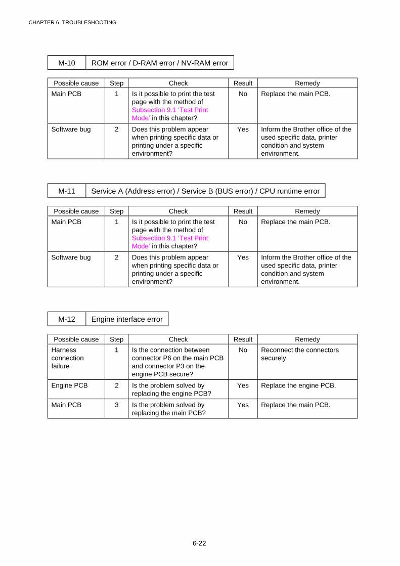
CHAPTER 6 TROUBLESHOOTING
6-22
M-10 ROM error / D-RAM error / NV-RAM error
Possible cause Step Check Result Remedy
Main PCB 1 Is it possible to print the testpage with the method ofSubsection 9.1 ‘Test PrintMode’ in this chapter?
No Replace the main PCB.
Software bug 2 Does this problem appearwhen printing specific data orprinting under a specificenvironment?
Yes Inform the Brother office of theused specific data, printercondition and systemenvironment.
M-11 Service A (Address error) / Service B (BUS error) / CPU runtime error
Possible cause Step Check Result Remedy
Main PCB 1 Is it possible to print the testpage with the method ofSubsection 9.1 ‘Test PrintMode’ in this chapter?
No Replace the main PCB.
Software bug 2 Does this problem appearwhen printing specific data orprinting under a specificenvironment?
Yes Inform the Brother office of theused specific data, printercondition and systemenvironment.
M-12 Engine interface error
Possible cause Step Check Result Remedy
Harnessconnectionfailure
1 Is the connection betweenconnector P6 on the main PCBand connector P3 on theengine PCB secure?
No Reconnect the connectorssecurely.
Engine PCB 2 Is the problem solved byreplacing the engine PCB?
Yes Replace the engine PCB.
Main PCB 3 Is the problem solved byreplacing the main PCB?
Yes Replace the main PCB.
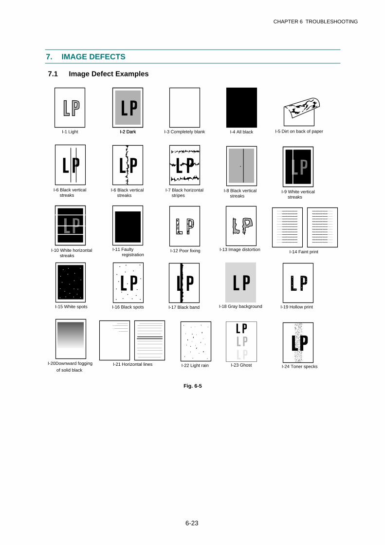
CHAPTER 6 TROUBLESHOOTING
6-23
7. IMAGE DEFECTS
7.1 Image Defect Examples
I-2 DarkI-1 Light I-2 Dark I-3 Completely blank I-4 All black I-5 Dirt on back of paper
I-6 Black vertical streaks
I-6 Black vertical streaks
I-7 Black horizontal stripes
I-12 Poor fixing I-13 Image distortion I-14 Faint print
Print out test print out test print out test Print out test print oPrint out test print out test print out test Print out test print o Print out test print o
Print out test print out test print out test Print out test print oPrint out test print out test print out test Print out test print o Print out test print o
Print out test print out test print out test Print out test print oPrint out test print out test print out test Print out test print o Print out test print o
Print out test print out test print out test Print out test print oPrint out test print out test print out test Print out test print o Print out test print o
Print out test print out test print out test Print out test print oPrint out test print out test print out test Print out test print o Print out test print o
Print out test print out test print out test Print out test print oPrint out test print out test print out test Print out test print o Print out test print o
Print out test print out test print out test Print out test print oPrint out test print out test print out test Print out test print o Print out test print o
Print out test print out test print out test Print out test print oPrint out test print out test print out test Print out test print o Print out test print o
Print out test print out test print out test Print out test print oPrint out test print out test print out test Print out test print o Print out test print o
Print out test print out test print out test Print out test print oPrint out test print out test print out test Print out test print o Print out test print o
Print out test print out test print out test Print out test print oPrint out test print out test print out test Print out test print o Print out test print o
Print out test print out test print out test Print out test print oPrint out test print out test print out test Print out test print o Print out test print o
Print out test print out test print out test Print out test print oPrint out test print out test print out test Print out test print o Print out test print o
Print out test print out test print out test Print out test print o Print out test print out test print out test Print out test print oPrint out test print o
Print out test print out test print out test Print out test print o Print out test print out test print out test Print out test print oPrint out test print o
Print out test print out test print out test Print out test print o Print out test print out test print out test Print out test print oPrint out test print o
Print out test print out test print out test Print out test print o Print out test print out test print out test Print out test print oPrint out test print o
Print out test print out test print out test Print out test print o Print out test print out test print out test Print out test print oPrint out test print o
Print out test print out test print out test Print out test print o Print out test print out test print out test Print out test print oPrint out test print o
Print out test print out test print out test Print out test print o Print out test print out test print out test Print out test print oPrint out test print o
Print out test print out test print out test Print out test print o Print out test print out test print out test Print out test print oPrint out test print o
Print out test print out test print out test Print out test print o Print out test print out test print out test Print out test print oPrint out test print o
Print out test print out test print out test Print out test print o Print out test print out test print out test Print out test print oPrint out test print o
Print out test print out test print out test Print out test print o Print out test print out test print out test Print out test print oPrint out test print o
Print out test print out test print out test Print out test print o Print out test print out test print out test Print out test print oPrint out test print o
Print out test print out test print out test Print out test print o Print out test print out test print out test Print out test print oPrint out test print o
I-19 Hollow printI-15 White spots I-16 Black spots I-18 Gray backgroundI-17 Black band
I-20Downward fogging
of solid blackI-21 Horizontal lines
I-11 Faulty registration
I-10 White horizontal streaks
I-8 Black vertical streaks
I-9 White vertical streaks
I-23 GhostI-22 Light rain I-24 Toner specks
Fig. 6-5
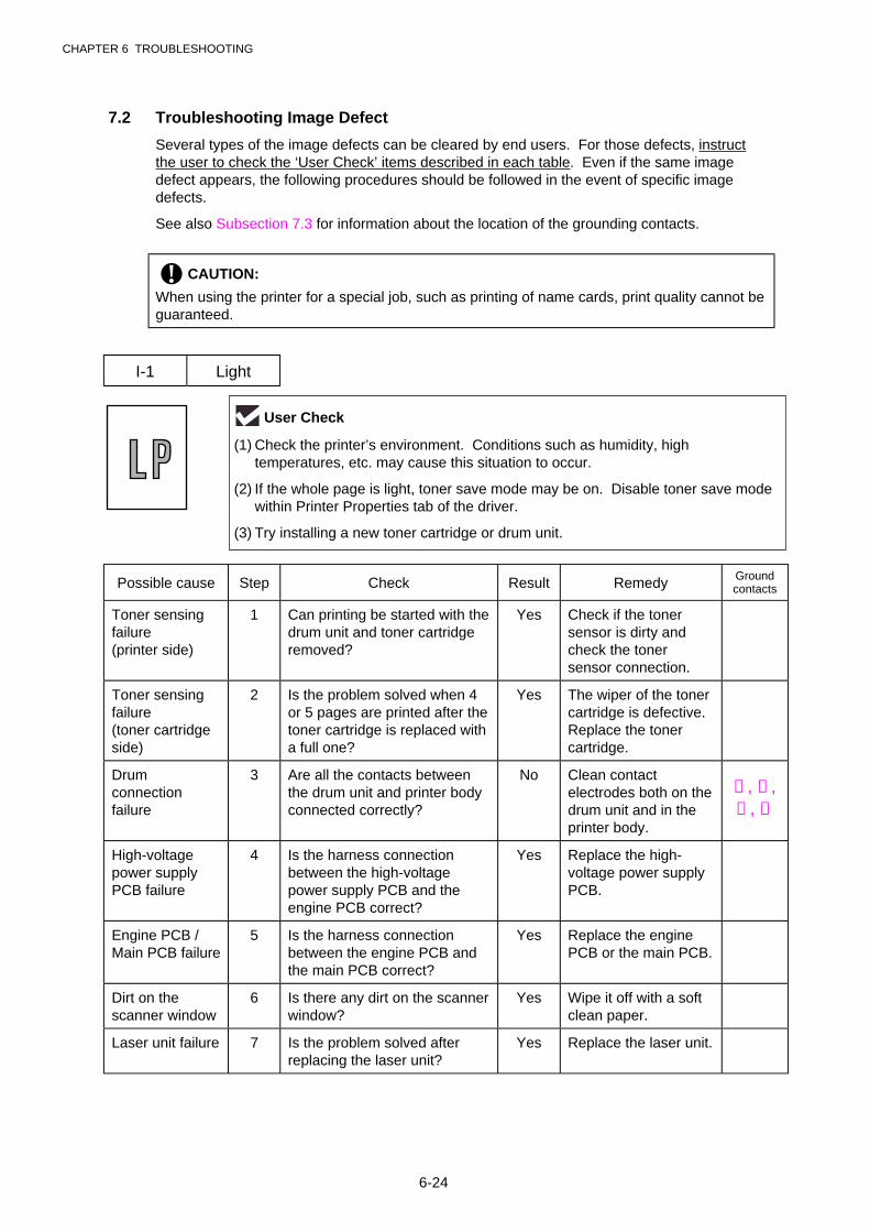
CHAPTER 6 TROUBLESHOOTING
6-24
7.2 Troubleshooting Image Defect
Several types of the image defects can be cleared by end users. For those defects, instructthe user to check the ‘User Check’ items described in each table. Even if the same imagedefect appears, the following procedures should be followed in the event of specific imagedefects.
See also Subsection 7.3 for information about the location of the grounding contacts.
! CAUTION:
When using the printer for a special job, such as printing of name cards, print quality cannot beguaranteed.
I-1 Light
Possible cause Step Check Result Remedy Groundcontacts
Toner sensingfailure(printer side)
1 Can printing be started with thedrum unit and toner cartridgeremoved?
Yes Check if the tonersensor is dirty andcheck the tonersensor connection.
Toner sensingfailure(toner cartridgeside)
2 Is the problem solved when 4or 5 pages are printed after thetoner cartridge is replaced witha full one?
Yes The wiper of the tonercartridge is defective.Replace the tonercartridge.
Drumconnectionfailure
3 Are all the contacts betweenthe drum unit and printer bodyconnected correctly?
No Clean contactelectrodes both on thedrum unit and in theprinter body.
➀ , ➃ ,➄ , ➅
High-voltagepower supplyPCB failure
4 Is the harness connectionbetween the high-voltagepower supply PCB and theengine PCB correct?
Yes Replace the high-voltage power supplyPCB.
Engine PCB /Main PCB failure
5 Is the harness connectionbetween the engine PCB andthe main PCB correct?
Yes Replace the enginePCB or the main PCB.
Dirt on thescanner window
6 Is there any dirt on the scannerwindow?
Yes Wipe it off with a softclean paper.
Laser unit failure 7 Is the problem solved afterreplacing the laser unit?
Yes Replace the laser unit.
User Check
(1) Check the printer’s environment. Conditions such as humidity, hightemperatures, etc. may cause this situation to occur.
(2) If the whole page is light, toner save mode may be on. Disable toner save modewithin Printer Properties tab of the driver.
(3) Try installing a new toner cartridge or drum unit.
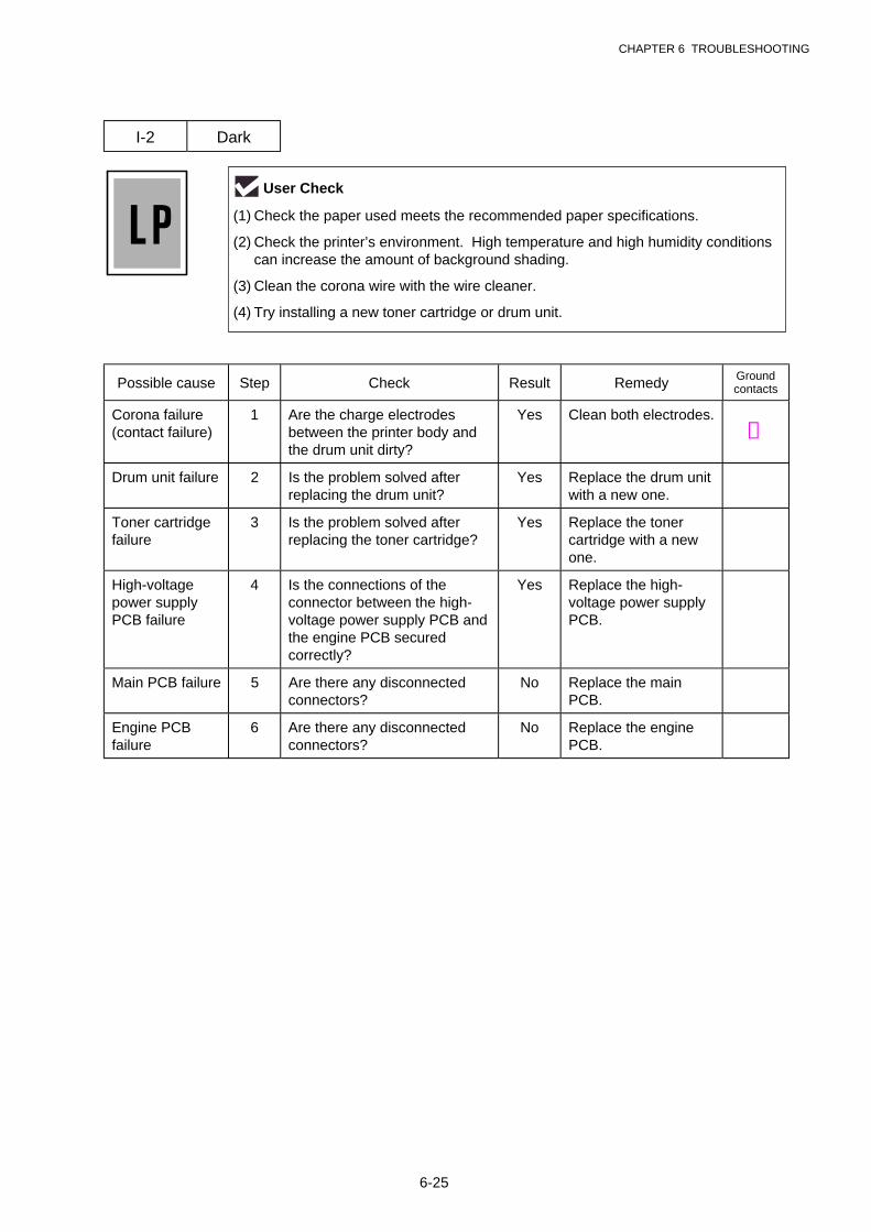
CHAPTER 6 TROUBLESHOOTING
6-25
I-2 Dark
Possible cause Step Check Result Remedy Groundcontacts
Corona failure(contact failure)
1 Are the charge electrodesbetween the printer body andthe drum unit dirty?
Yes Clean both electrodes.➂
Drum unit failure 2 Is the problem solved afterreplacing the drum unit?
Yes Replace the drum unitwith a new one.
Toner cartridgefailure
3 Is the problem solved afterreplacing the toner cartridge?
Yes Replace the tonercartridge with a newone.
High-voltagepower supplyPCB failure
4 Is the connections of theconnector between the high-voltage power supply PCB andthe engine PCB securedcorrectly?
Yes Replace the high-voltage power supplyPCB.
Main PCB failure 5 Are there any disconnectedconnectors?
No Replace the mainPCB.
Engine PCBfailure
6 Are there any disconnectedconnectors?
No Replace the enginePCB.
User Check
(1) Check the paper used meets the recommended paper specifications.
(2) Check the printer’s environment. High temperature and high humidity conditionscan increase the amount of background shading.
(3) Clean the corona wire with the wire cleaner.
(4) Try installing a new toner cartridge or drum unit.

CHAPTER 6 TROUBLESHOOTING
6-26
I-3 Completely blank
Possible cause Step Check Result Remedy Groundcontacts
Developing biascontact failure
1 Are the developing biascontacts between the printerbody and drum unit dirty?
Yes Clean the electrodesat both sides. ➃
Drum unit 2 Are the drum shaft and drumelectrode of the printer bodyconnected correctly?
Yes Clean the shaft andthe electrode. ➀
No Check the connectionbetween the shaft andthe electrode.
➀
Drum unit failure 3 Is the problem solved afterreplacing the drum unit?
Yes Replace the drumunit.
Toner cartridgefailure
4 Is the problem solved afterreplacing the toner cartridge?
Yes Replace the tonercartridge with a newone.
Scannerharnessconnectionfailure
5 Is the scanner harnessconnected securely?(Check if there is any play inthe connection.)
No Reconnect theconnector correctly.
Main PCB failure 6 Are printing signals being inputto the laser unit?
Is the problem solved afterreplacing the main PCB?
Yes Replace the mainPCB.
Laser unit failure 7 Is the scanner interlock leverdamaged?
Yes Replace the laser unit.
Is the scanner mirror broken orloose?
No Replace the high-voltage power supplyPCB.

CHAPTER 6 TROUBLESHOOTING
6-27
I-4 All black
Possible cause Step Check Result Remedy Groundcontacts
Corona failure 1 Is the corona wire dirty? Yes Clean the corona wirewith the wire cleaner. ➁
2 Is the corona wire broken? Yes Replace the drumunit.
3 Are the charge electrodesbetween the printer body andthe drum unit dirty?
Yes Clean both electrodes.➂
Harnessconnection
4 Is the laser unit connected tothe main PCB correctly?
No Connect the harnessbetween the laser unitand the main PCBcorrectly.
High-voltagepower supplyPCB failure
5 Is the problem solved afterreplacing the high-voltagepower supply PCB?
Yes Replace the high-voltage power supplyPCB.
Main PCB failure 6 Is the problem solved afterreplacing the main PCB?
Yes Replace the mainPCB.
User Check
(1) Clean the corona wire of the drum unit.
(2) The drum unit may be damaged. Install a new drum unit.
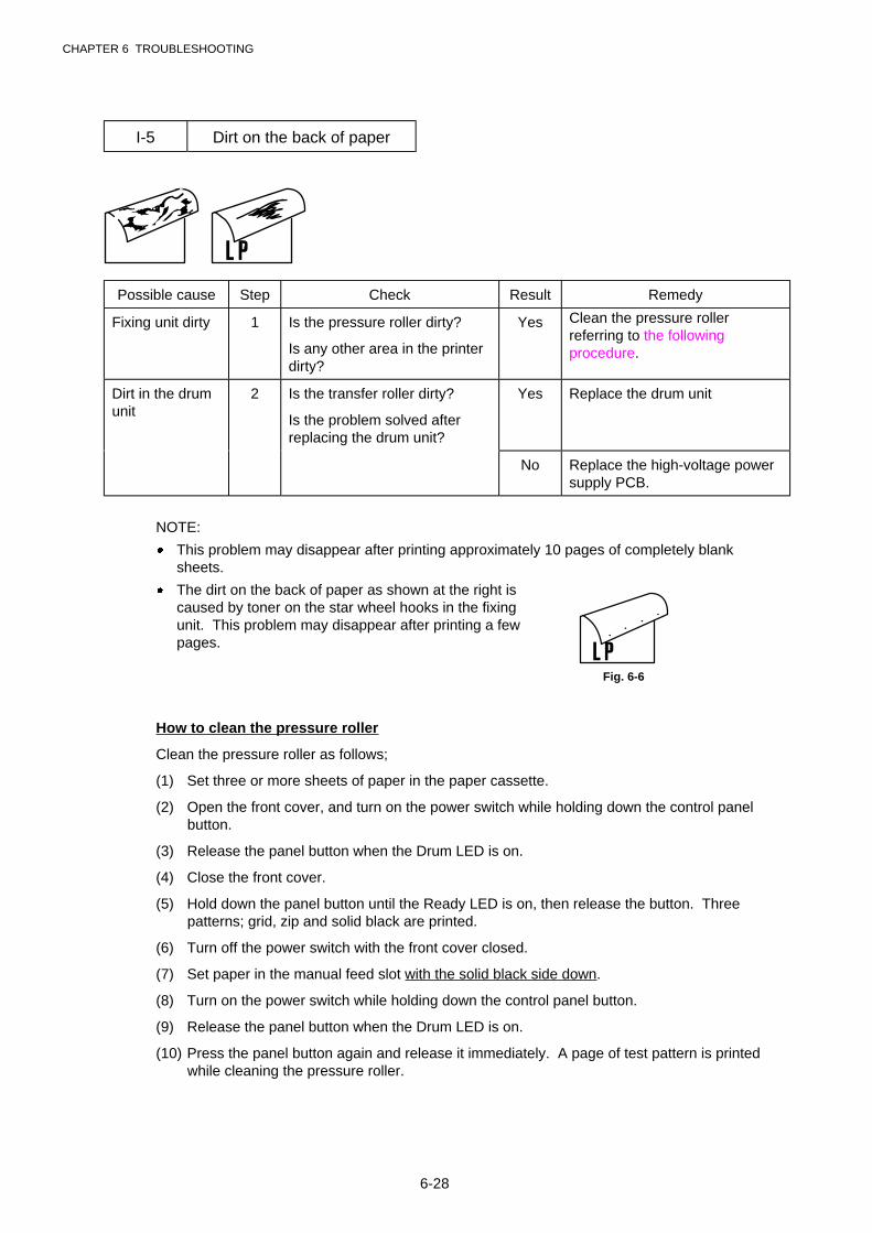
CHAPTER 6 TROUBLESHOOTING
6-28
I-5 Dirt on the back of paper
Possible cause Step Check Result Remedy
Fixing unit dirty 1 Is the pressure roller dirty?
Is any other area in the printerdirty?
Yes Clean the pressure rollerreferring to the followingprocedure.
Dirt in the drumunit
2 Is the transfer roller dirty?
Is the problem solved afterreplacing the drum unit?
Yes Replace the drum unit
No Replace the high-voltage powersupply PCB.
NOTE:
· This problem may disappear after printing approximately 10 pages of completely blanksheets.
· The dirt on the back of paper as shown at the right iscaused by toner on the star wheel hooks in the fixingunit. This problem may disappear after printing a fewpages.
Fig. 6-6
How to clean the pressure roller
Clean the pressure roller as follows;
(1) Set three or more sheets of paper in the paper cassette.
(2) Open the front cover, and turn on the power switch while holding down the control panelbutton.
(3) Release the panel button when the Drum LED is on.
(4) Close the front cover.
(5) Hold down the panel button until the Ready LED is on, then release the button. Threepatterns; grid, zip and solid black are printed.
(6) Turn off the power switch with the front cover closed.
(7) Set paper in the manual feed slot with the solid black side down.
(8) Turn on the power switch while holding down the control panel button.
(9) Release the panel button when the Drum LED is on.
(10) Press the panel button again and release it immediately. A page of test pattern is printedwhile cleaning the pressure roller.
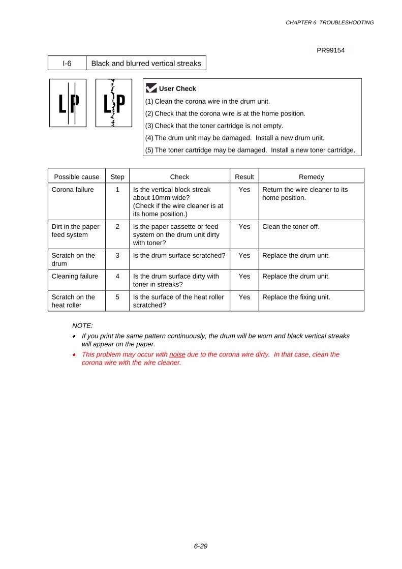
CHAPTER 6 TROUBLESHOOTING
6-29
I-6 Black and blurred vertical streaks
Possible cause Step Check Result Remedy
Corona failure 1 Is the vertical block streakabout 10mm wide?(Check if the wire cleaner is atits home position.)
Yes Return the wire cleaner to itshome position.
Dirt in the paperfeed system
2 Is the paper cassette or feedsystem on the drum unit dirtywith toner?
Yes Clean the toner off.
Scratch on thedrum
3 Is the drum surface scratched? Yes Replace the drum unit.
Cleaning failure 4 Is the drum surface dirty withtoner in streaks?
Yes Replace the drum unit.
Scratch on theheat roller
5 Is the surface of the heat rollerscratched?
Yes Replace the fixing unit.
NOTE:
� If you print the same pattern continuously, the drum will be worn and black vertical streakswill appear on the paper.
� This problem may occur with noise due to the corona wire dirty. In that case, clean thecorona wire with the wire cleaner.
User Check
(1) Clean the corona wire in the drum unit.
(2) Check that the corona wire is at the home position.
(3) Check that the toner cartridge is not empty.
(4) The drum unit may be damaged. Install a new drum unit.
(5) The toner cartridge may be damaged. Install a new toner cartridge.
PR99154
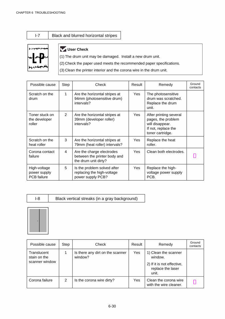
CHAPTER 6 TROUBLESHOOTING
6-30
I-7 Black and blurred horizontal stripes
Possible cause Step Check Result Remedy Groundcontacts
Scratch on thedrum
1 Are the horizontal stripes at94mm (photosensitive drum)intervals?
Yes The photosensitivedrum was scratched.Replace the drumunit.
Toner stuck onthe developerroller
2 Are the horizontal stripes at39mm (developer roller)intervals?
Yes After printing severalpages, the problemwill disappear.If not, replace thetoner cartridge.
Scratch on theheat roller
3 Are the horizontal stripes at79mm (heat roller) intervals?
Yes Replace the heatroller.
Corona contactfailure
4 Are the charge electrodesbetween the printer body andthe drum unit dirty?
Yes Clean both electrodes.➂
High-voltagepower supplyPCB failure
5 Is the problem solved afterreplacing the high-voltagepower supply PCB?
Yes Replace the high-voltage power supplyPCB.
I-8 Black vertical streaks (in a gray background)
Possible cause Step Check Result Remedy Groundcontacts
Translucentstain on thescanner window
1 Is there any dirt on the scannerwindow?
Yes 1) Clean the scannerwindow.
2) If it is not effective,replace the laserunit.
Corona failure 2 Is the corona wire dirty? Yes Clean the corona wirewith the wire cleaner. ➁
User Check
(1) The drum unit may be damaged. Install a new drum unit.
(2) Check the paper used meets the recommended paper specifications.
(3) Clean the printer interior and the corona wire in the drum unit.
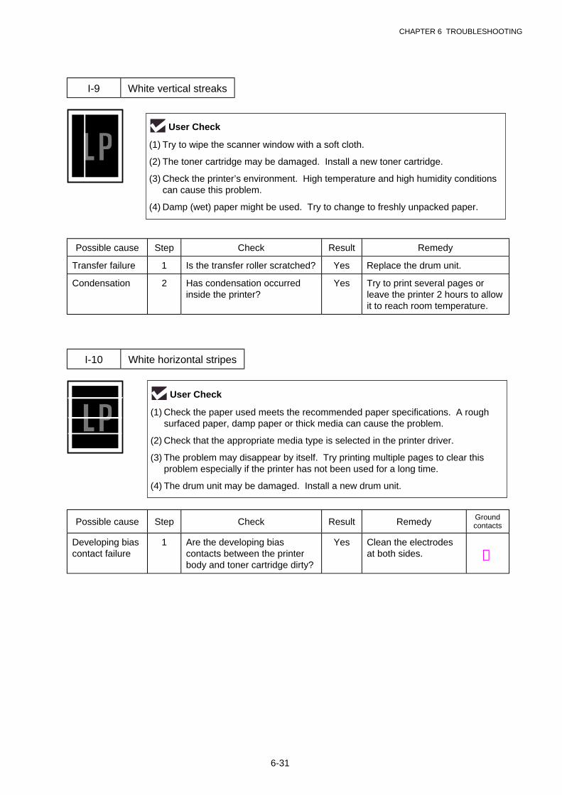
CHAPTER 6 TROUBLESHOOTING
6-31
I-9 White vertical streaks
Possible cause Step Check Result Remedy
Transfer failure 1 Is the transfer roller scratched? Yes Replace the drum unit.
Condensation 2 Has condensation occurredinside the printer?
Yes Try to print several pages orleave the printer 2 hours to allowit to reach room temperature.
I-10 White horizontal stripes
Possible cause Step Check Result Remedy Groundcontacts
Developing biascontact failure
1 Are the developing biascontacts between the printerbody and toner cartridge dirty?
Yes Clean the electrodesat both sides. ➃
User Check
(1) Try to wipe the scanner window with a soft cloth.
(2) The toner cartridge may be damaged. Install a new toner cartridge.
(3) Check the printer’s environment. High temperature and high humidity conditionscan cause this problem.
(4) Damp (wet) paper might be used. Try to change to freshly unpacked paper.
User Check
(1) Check the paper used meets the recommended paper specifications. A roughsurfaced paper, damp paper or thick media can cause the problem.
(2) Check that the appropriate media type is selected in the printer driver.
(3) The problem may disappear by itself. Try printing multiple pages to clear thisproblem especially if the printer has not been used for a long time.
(4) The drum unit may be damaged. Install a new drum unit.
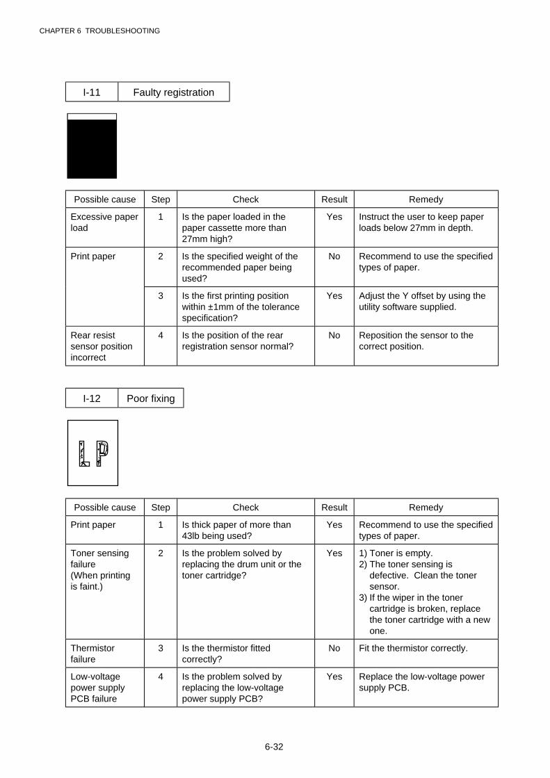
CHAPTER 6 TROUBLESHOOTING
6-32
I-11 Faulty registration
Possible cause Step Check Result Remedy
Excessive paperload
1 Is the paper loaded in thepaper cassette more than27mm high?
Yes Instruct the user to keep paperloads below 27mm in depth.
Print paper 2 Is the specified weight of therecommended paper beingused?
No Recommend to use the specifiedtypes of paper.
3 Is the first printing positionwithin ±1mm of the tolerancespecification?
Yes Adjust the Y offset by using theutility software supplied.
Rear resistsensor positionincorrect
4 Is the position of the rearregistration sensor normal?
No Reposition the sensor to thecorrect position.
I-12 Poor fixing
Possible cause Step Check Result Remedy
Print paper 1 Is thick paper of more than43lb being used?
Yes Recommend to use the specifiedtypes of paper.
Toner sensingfailure(When printingis faint.)
2 Is the problem solved byreplacing the drum unit or thetoner cartridge?
Yes 1) Toner is empty.2) The toner sensing is
defective. Clean the tonersensor.
3) If the wiper in the tonercartridge is broken, replacethe toner cartridge with a newone.
Thermistorfailure
3 Is the thermistor fittedcorrectly?
No Fit the thermistor correctly.
Low-voltagepower supplyPCB failure
4 Is the problem solved byreplacing the low-voltagepower supply PCB?
Yes Replace the low-voltage powersupply PCB.
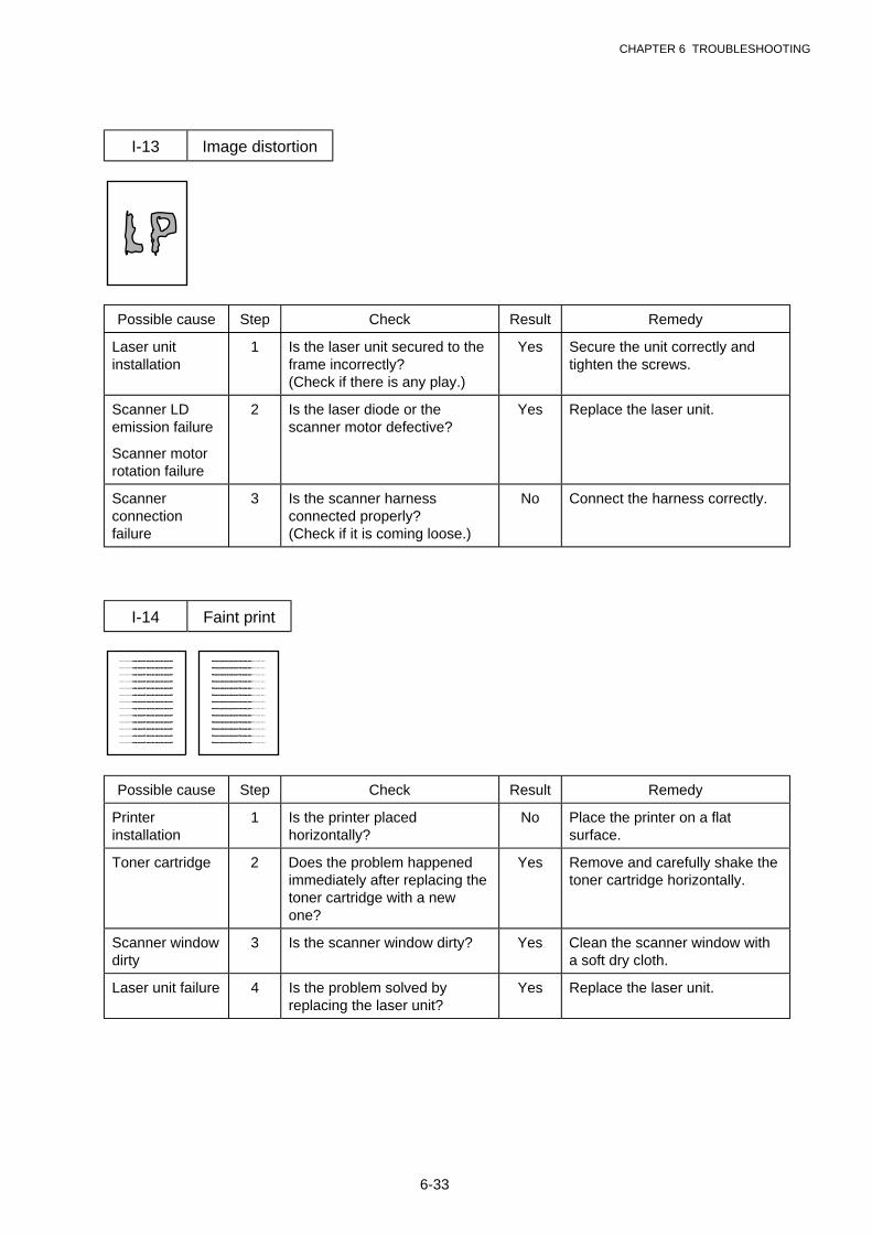
CHAPTER 6 TROUBLESHOOTING
6-33
I-13 Image distortion
Possible cause Step Check Result Remedy
Laser unitinstallation
1 Is the laser unit secured to theframe incorrectly?(Check if there is any play.)
Yes Secure the unit correctly andtighten the screws.
Scanner LDemission failure
Scanner motorrotation failure
2 Is the laser diode or thescanner motor defective?
Yes Replace the laser unit.
Scannerconnectionfailure
3 Is the scanner harnessconnected properly?(Check if it is coming loose.)
No Connect the harness correctly.
I-14 Faint print
Print out test print out test print out test Print out test print o Print out test print o
Print out test print out test print out test Print out test print o Print out test print o
Print out test print out test print out test Print out test print o Print out test print o
Print out test print out test print out test Print out test print o Print out test print o
Print out test print out test print out test Print out test print o Print out test print o
Print out test print out test print out test Print out test print o Print out test print o
Print out test print out test print out test Print out test print o Print out test print o
Print out test print out test print out test Print out test print o Print out test print o
Print out test print out test print out test Print out test print o Print out test print o
Print out test print out test print out test Print out test print o Print out test print o
Print out test print out test print out test Print out test print o Print out test print o
Print out test print out test print out test Print out test print o Print out test print o
Print out test print out test print out test Print out test print o Print out test print o
Print out test print out test print out test Print out test print oPrint out test print o
Print out test print out test print out test Print out test print oPrint out test print o
Print out test print out test print out test Print out test print oPrint out test print o
Print out test print out test print out test Print out test print oPrint out test print o
Print out test print out test print out test Print out test print oPrint out test print o
Print out test print out test print out test Print out test print oPrint out test print o
Print out test print out test print out test Print out test print oPrint out test print o
Print out test print out test print out test Print out test print oPrint out test print o
Print out test print out test print out test Print out test print oPrint out test print o
Print out test print out test print out test Print out test print oPrint out test print o
Print out test print out test print out test Print out test print oPrint out test print o
Print out test print out test print out test Print out test print oPrint out test print o
Print out test print out test print out test Print out test print oPrint out test print o
Possible cause Step Check Result Remedy
Printerinstallation
1 Is the printer placedhorizontally?
No Place the printer on a flatsurface.
Toner cartridge 2 Does the problem happenedimmediately after replacing thetoner cartridge with a newone?
Yes Remove and carefully shake thetoner cartridge horizontally.
Scanner windowdirty
3 Is the scanner window dirty? Yes Clean the scanner window witha soft dry cloth.
Laser unit failure 4 Is the problem solved byreplacing the laser unit?
Yes Replace the laser unit.
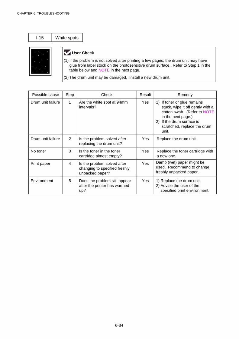
CHAPTER 6 TROUBLESHOOTING
6-34
I-15 White spots
Possible cause Step Check Result Remedy
Drum unit failure 1 Are the white spot at 94mmintervals?
Yes 1) If toner or glue remainsstuck, wipe it off gently with acotton swab. (Refer to NOTEin the next page.)
2) If the drum surface isscratched, replace the drumunit.
Drum unit failure 2 Is the problem solved afterreplacing the drum unit?
Yes Replace the drum unit.
No toner 3 Is the toner in the tonercartridge almost empty?
Yes Replace the toner cartridge witha new one.
Print paper 4 Is the problem solved afterchanging to specified freshlyunpacked paper?
Yes Damp (wet) paper might beused. Recommend to changefreshly unpacked paper.
Environment 5 Does the problem still appearafter the printer has warmedup?
Yes 1) Replace the drum unit.2) Advise the user of the
specified print environment.
User Check
(1) If the problem is not solved after printing a few pages, the drum unit may haveglue from label stock on the photosensitive drum surface. Refer to Step 1 in thetable below and NOTE in the next page.
(2) The drum unit may be damaged. Install a new drum unit.
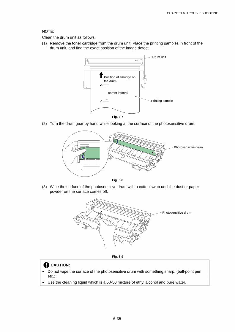
CHAPTER 6 TROUBLESHOOTING
6-35
NOTE:
Clean the drum unit as follows:
(1) Remove the toner cartridge from the drum unit Place the printing samples in front of thedrum unit, and find the exact position of the image defect.
Fig. 6-7
(2) Turn the drum gear by hand while looking at the surface of the photosensitive drum.
Fig. 6-8
(3) Wipe the surface of the photosensitive drum with a cotton swab until the dust or paperpowder on the surface comes off.
Fig. 6-9
! CAUTION:
· Do not wipe the surface of the photosensitive drum with something sharp. (ball-point penetc.)
· Use the cleaning liquid which is a 50-50 mixture of ethyl alcohol and pure water.
Position of smudge onthe drum
94mm interval
Printing sample
Drum unit
Photosensitive drum
Photosensitive drum
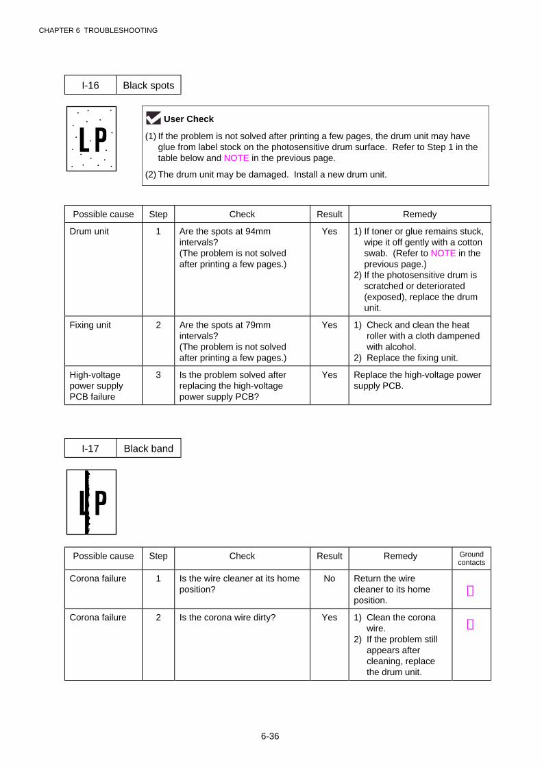
CHAPTER 6 TROUBLESHOOTING
6-36
I-16 Black spots
Possible cause Step Check Result Remedy
Drum unit 1 Are the spots at 94mmintervals?(The problem is not solvedafter printing a few pages.)
Yes 1) If toner or glue remains stuck,wipe it off gently with a cottonswab. (Refer to NOTE in theprevious page.)
2) If the photosensitive drum isscratched or deteriorated(exposed), replace the drumunit.
Fixing unit 2 Are the spots at 79mmintervals?(The problem is not solvedafter printing a few pages.)
Yes 1) Check and clean the heatroller with a cloth dampenedwith alcohol.
2) Replace the fixing unit.
High-voltagepower supplyPCB failure
3 Is the problem solved afterreplacing the high-voltagepower supply PCB?
Yes Replace the high-voltage powersupply PCB.
I-17 Black band
Possible cause Step Check Result Remedy Groundcontacts
Corona failure 1 Is the wire cleaner at its homeposition?
No Return the wirecleaner to its homeposition.
➁
Corona failure 2 Is the corona wire dirty? Yes 1) Clean the coronawire.
2) If the problem stillappears aftercleaning, replacethe drum unit.
➁
User Check
(1) If the problem is not solved after printing a few pages, the drum unit may haveglue from label stock on the photosensitive drum surface. Refer to Step 1 in thetable below and NOTE in the previous page.
(2) The drum unit may be damaged. Install a new drum unit.
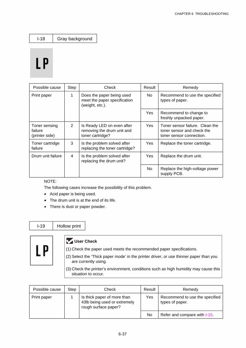
CHAPTER 6 TROUBLESHOOTING
6-37
I-18 Gray background
Possible cause Step Check Result Remedy
Print paper 1 Does the paper being usedmeet the paper specification(weight, etc.).
No Recommend to use the specifiedtypes of paper.
Yes Recommend to change tofreshly unpacked paper.
Toner sensingfailure(printer side)
2 Is Ready LED on even afterremoving the drum unit andtoner cartridge?
Yes Toner sensor failure. Clean thetoner sensor and check thetoner sensor connection.
Toner cartridgefailure
3 Is the problem solved afterreplacing the toner cartridge?
Yes Replace the toner cartridge.
Drum unit failure 4 Is the problem solved afterreplacing the drum unit?
Yes Replace the drum unit.
No Replace the high-voltage powersupply PCB.
NOTE:
The following cases increase the possibility of this problem.
· Acid paper is being used.
· The drum unit is at the end of its life.
· There is dust or paper powder.
I-19 Hollow print
Possible cause Step Check Result Remedy
Print paper 1 Is thick paper of more than43lb being used or extremelyrough surface paper?
Yes Recommend to use the specifiedtypes of paper.
No Refer and compare with I-15.
User Check
(1) Check the paper used meets the recommended paper specifications.
(2) Select the ‘Thick paper mode’ in the printer driver, or use thinner paper than youare currently using.
(3) Check the printer’s environment, conditions such as high humidity may cause thissituation to occur.

CHAPTER 6 TROUBLESHOOTING
6-38
I-20 Downward fogging of solid black
Possible cause Step Check Result Remedy
Toner cartridgefailure
1 Is the problem solved afterreplacing the toner cartridge?
Yes Replace the toner cartridge.
High-voltagepower supplyPCB failure
2 Is the problem solved afterreplacing the high-voltagepower supply PCB?
Yes Replace the high-voltage powersupply PCB.
I-21 Horizontal lines
Possible cause Step Check Result Remedy Groundcontacts
Paper feed roller 1 Are the feed roller shaft andthe ground contact connectedcorrectly?
No Check the connectionbetween the shaft andthe ground contact.
Also check the groundcontact on the back ofthe feed roller. Referto P.4-24.
Paper cassettecontacts
2 Are the ground contacts on theback side of the paper cassetteconnecting correctly?
No Clean the contacts.➆
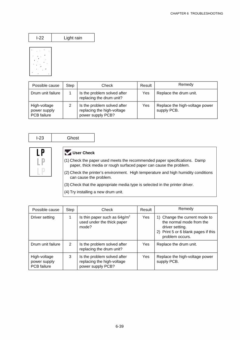
CHAPTER 6 TROUBLESHOOTING
6-39
I-22 Light rain
Possible cause Step Check Result Remedy
Drum unit failure 1 Is the problem solved afterreplacing the drum unit?
Yes Replace the drum unit.
High-voltagepower supplyPCB failure
2 Is the problem solved afterreplacing the high-voltagepower supply PCB?
Yes Replace the high-voltage powersupply PCB.
I-23 Ghost
Possible cause Step Check Result Remedy
Driver setting 1 Is thin paper such as 64g/m2
used under the thick papermode?
Yes 1) Change the current mode tothe normal mode from thedriver setting.
2) Print 5 or 6 blank pages if thisproblem occurs.
Drum unit failure 2 Is the problem solved afterreplacing the drum unit?
Yes Replace the drum unit.
High-voltagepower supplyPCB failure
3 Is the problem solved afterreplacing the high-voltagepower supply PCB?
Yes Replace the high-voltage powersupply PCB.
User Check
(1) Check the paper used meets the recommended paper specifications. Damppaper, thick media or rough surfaced paper can cause the problem.
(2) Check the printer’s environment. High temperature and high humidity conditionscan cause the problem.
(3) Check that the appropriate media type is selected in the printer driver.
(4) Try installing a new drum unit.

CHAPTER 6 TROUBLESHOOTING
6-40
I-24 Toner specks
User Check
(1) Check the paper used meets the recommended paper specifications. A roughsurfaced paper may cause the problem.
(2) The toner cartridge may be damaged. Install a new toner cartridge.
(3) The drum unit may be damaged, or may be nearly at the end of life. Install a newdrum unit.

CHAPTER 6 TROUBLESHOOTING
6-41
7.3 Location of Grounding Contacts
7.3.1 Drum unit
Fig. 6-10
7.3.2 Printer body & Paper cassette
Fig. 6-11
Drum Unit
Paper Cassette
➁ Wire cleaner
➂ Charge➀ Photosensitive drum
➃ Development roller
➆ Ground
➄ Grid
➄ Grid
➂ Charge
➀ Photosensitive drum
➃ Development roller
➅ Transfer roller
➅ Transfer roller
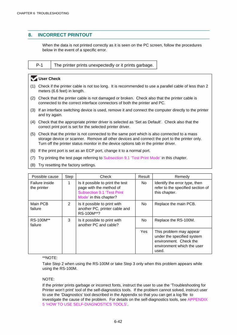
CHAPTER 6 TROUBLESHOOTING
6-42
8. INCORRECT PRINTOUT
When the data is not printed correctly as it is seen on the PC screen, follow the proceduresbelow in the event of a specific error.
P-1 The printer prints unexpectedly or it prints garbage.
User Check
(1) Check if the printer cable is not too long. It is recommended to use a parallel cable of less than 2meters (6.6 feet) in length.
(2) Check that the printer cable is not damaged or broken. Check also that the printer cable isconnected to the correct interface connectors of both the printer and PC.
(3) If an interface switching device is used, remove it and connect the computer directly to the printerand try again.
(4) Check that the appropriate printer driver is selected as ‘Set as Default’. Check also that thecorrect print port is set for the selected printer driver.
(5) Check that the printer is not connected to the same port which is also connected to a massstorage device or scanner. Remove all other devices and connect the port to the printer only.Turn off the printer status monitor in the device options tab in the printer driver.
(6) If the print port is set as an ECP port, change it to a normal port.
(7) Try printing the test page referring to Subsection 9.1 ‘Test Print Mode’ in this chapter.
(8) Try resetting the factory settings.
Possible cause Step Check Result Remedy
Failure insidethe printer
1 Is it possible to print the testpage with the method ofSubsection 9.1 ‘Test PrintMode’ in this chapter?
No Identify the error type, thenrefer to the specified section ofthis chapter.
Main PCBfailure
2 Is it possible to print withanother PC, printer cable andRS-100M**?
No Replace the main PCB.
RS-100M**failure
3 Is it possible to print withanother PC and cable?
No Replace the RS-100M.
Yes This problem may appearunder the specified systemenvironment. Check theenvironment which the userused.
**NOTE:
Take Step 2 when using the RS-100M or take Step 3 only when this problem appears whileusing the RS-100M.
NOTE:
If the printer prints garbage or incorrect fonts, instruct the user to use the ‘Troubleshooting forPrinter won’t print’ tool of the self-diagnostics tools. If the problem cannot solved, instruct userto use the ‘Diagnostics’ tool described in the Appendix so that you can get a log file toinvestigate the cause of the problem. For details on the self-diagnostics tools, see APPENDIX5 ‘HOW TO USE SELF-DIAGNOSTICS TOOLS’.
CHAPTER 6 TROUBLESHOOTING
6-43
P-2 Unable to print full pages of a document with the “PRINT OVERRUN” message.
User Check
(1) Press the panel button to print the data remaining in the printer.
(2) If this does not clear the error, reduce the complexity of your document or reduce the printerresolution.
(3) Expand the printer memory by adding a commercially available SIMM. (HL-1250 only)
(4) Change the following setting in the printer driver and try again. The best combination of settingsbelow will vary depending on your document. (HL-1250 only)
Graphic Mode / TrueTypeTM mode / Use Printer TrueTypeTM Fonts.
NOTE:
This problem may appear if the data is too complex. If it is not cleared by taking the actionsabove, it will be impossible to print such data under the printer specifications.
P-3 Unable to print full pages of a document with the “MEMORY FULL” message.
User Check
(1) Press the panel button to print the data remaining in the printer.
(2) Reduce the complexity of your document or reduce the printer resolution.
(3) Expand the printer memory by adding a commercially available SIMM. (HL-1250 only)
NOTE:
This problem may appear if the data is too complex.
For the HL-1240 printer, if it is not cleared by taking the actions above, it will be impossible toprint such data under the printer specifications.
For the HL-1250 printer, take the following procedures.
<For HL-1250 only>
Possible cause Step Check Result Remedy
Unable torecognize SIMM
1 Check the memory size in PrintConfiguration. Is it the defaultsize?
Yes Expand the memory size byadding SIMM.
If the memory is already at themaximum size, it will beimpossible to print the dataunder the printerspecifications.
SIMM / mainPCB failure
2 Try installing SIMM intoanother printer, then check thememory size in PrintConfiguration.
Yes Replace the SIMM.
Is it possible to print the data? No Replace the main PCB.
CHAPTER 6 TROUBLESHOOTING
6-44
P-4 Headers or footers are not printed out even though they are viewed on PC screen.
User Check
Most laser printers have a restricted area that cannot be printed on. Usually the first two lines and lasttwo lines of text cannot print (leaving 62 printable lines). Adjust the top and bottom margins in yourdocument to allow for this.
P-5 The printer prints the first couple of pages correctly, then some pages have text missing.
User Check
(For connecting by RS-232C/422A on HL-1250 only)
A problem related to serial interface setting. The PC is not recognizing the printer’s input buffer fullsignal. Causes could be incorrect serial cable (incorrectly wired or too long) or incorrect setting of thecomputer serial interface.
P-6 The printer sometimes prints a couple of characters and then ejects the page.
User Check
(For DOS environment only)
The application printer emulation setting and the printer’s emulation do not match. Check in theapplication software which printer you have selected to make sure the printer is set up correctly.Remember that the printer emulates widely used printer selections:
HL-1240: HP LaserJet IIPHL-1250: HP LaserJet 6P, Epson FX-850 IBM Proprinter XL
Try setting the printer into HP emulation and then select the HP LaserJet IIP (for HL-1240) or HPLaserJet 6P (for HL-1250) printer in the application software.
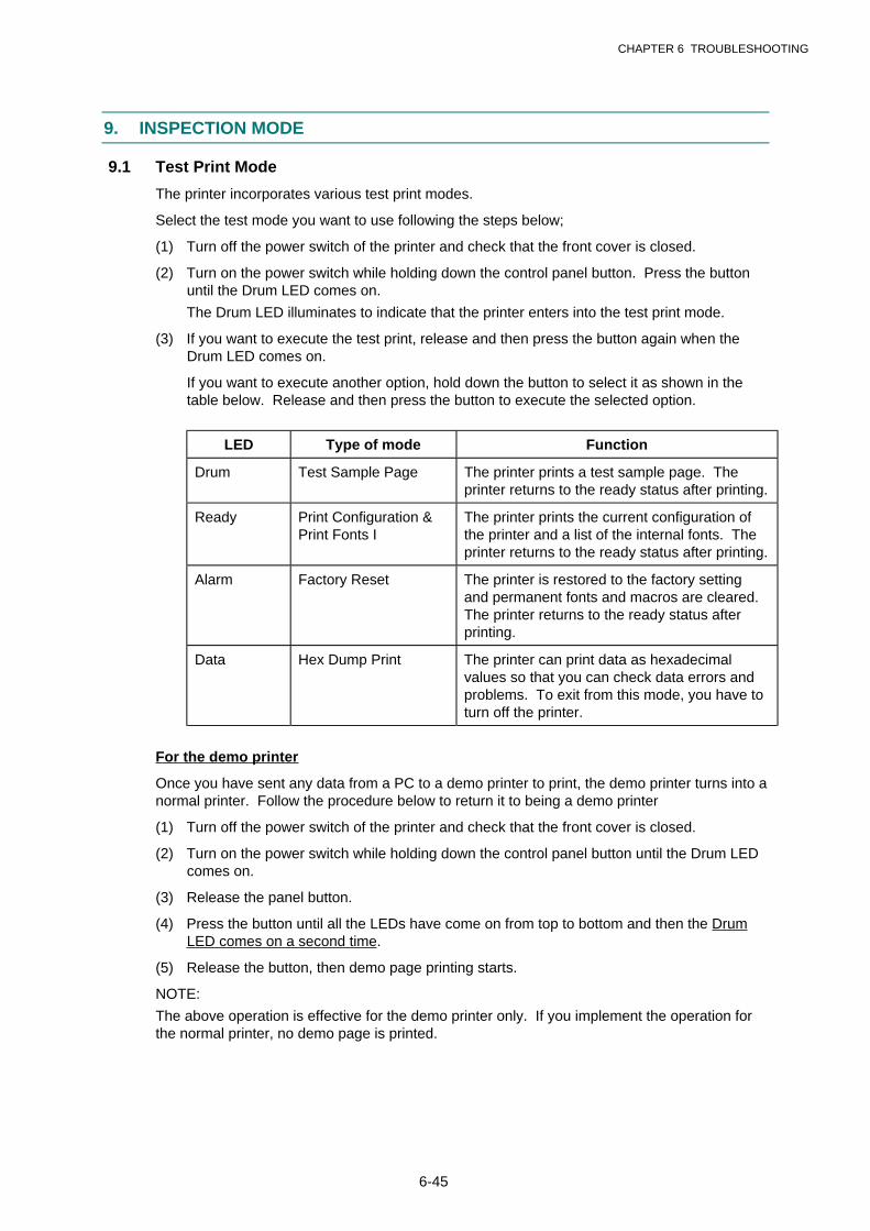
CHAPTER 6 TROUBLESHOOTING
6-45
9. INSPECTION MODE
9.1 Test Print Mode
The printer incorporates various test print modes.
Select the test mode you want to use following the steps below;
(1) Turn off the power switch of the printer and check that the front cover is closed.
(2) Turn on the power switch while holding down the control panel button. Press the buttonuntil the Drum LED comes on.
The Drum LED illuminates to indicate that the printer enters into the test print mode.
(3) If you want to execute the test print, release and then press the button again when theDrum LED comes on.
If you want to execute another option, hold down the button to select it as shown in thetable below. Release and then press the button to execute the selected option.
LED Type of mode Function
Drum Test Sample Page The printer prints a test sample page. Theprinter returns to the ready status after printing.
Ready Print Configuration &Print Fonts I
The printer prints the current configuration ofthe printer and a list of the internal fonts. Theprinter returns to the ready status after printing.
Alarm Factory Reset The printer is restored to the factory settingand permanent fonts and macros are cleared.The printer returns to the ready status afterprinting.
Data Hex Dump Print The printer can print data as hexadecimalvalues so that you can check data errors andproblems. To exit from this mode, you have toturn off the printer.
For the demo printer
Once you have sent any data from a PC to a demo printer to print, the demo printer turns into anormal printer. Follow the procedure below to return it to being a demo printer
(1) Turn off the power switch of the printer and check that the front cover is closed.
(2) Turn on the power switch while holding down the control panel button until the Drum LEDcomes on.
(3) Release the panel button.
(4) Press the button until all the LEDs have come on from top to bottom and then the DrumLED comes on a second time.
(5) Release the button, then demo page printing starts.
NOTE:
The above operation is effective for the demo printer only. If you implement the operation forthe normal printer, no demo page is printed.

CHAPTER 6 TROUBLESHOOTING
6-46
9.2 Inspection Mode
The printer incorporates various inspection modes such as the factory inspection mode andthe test print mode.
The printer supports a factory inspection mode, continuous grid pattern print mode, 3 patternsprint mode and NV-RAM value dump mode.
Select the inspection mode you want to use following the steps below;
(1) Turn off the power switch of the printer
(2) Open the front cover, and turn on the power switch while holding down the control panelbutton.
(3) When the printer enters into the inspection mode, the Drum LED is ON. Holding down thepanel button will cause the LEDs to turn ON in the order Drum ® Ready ® Alarm ® Data® Drum. When you release the button, a mode is selected.
The mode selected is indicated by the LED which is ON when you release the button.
The inspection modes are assigned to the respective LEDs as shown below;
LED Type of inspection
Drum Factory inspection mode
Ready Continuous grid pattern print mode
Alarm 3 patterns print mode (grid, zip, black)
Data NV-RAM value dump mode**
Drum + Ready ROM code reprogramming mode (only whenflash memory is fitted)
Ready + Alarm RAM check
Alarm + Data 4% density pattern print mode
**NOTE:
The NV-RAM value dump mode is not incorporated in the US model.
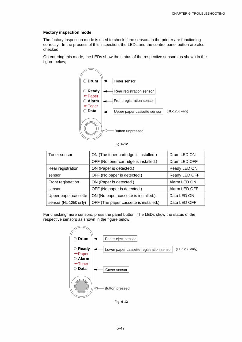
CHAPTER 6 TROUBLESHOOTING
6-47
Factory inspection mode
The factory inspection mode is used to check if the sensors in the printer are functioningcorrectly. In the process of this inspection, the LEDs and the control panel button are alsochecked.
On entering this mode, the LEDs show the status of the respective sensors as shown in thefigure below;
Toner sensor
Button unpressed
Rear registration sensor
Front registration sensor
Upper paper cassette sensor
Drum
Ready
AlarmPaper
TonerData
Fig. 6-12
Toner sensor ON (The toner cartridge is installed.) Drum LED ON
OFF (No toner cartridge is installed.) Drum LED OFF
Rear registration ON (Paper is detected.) Ready LED ON
sensor OFF (No paper is detected.) Ready LED OFF
Front registration ON (Paper is detected.) Alarm LED ON
sensor OFF (No paper is detected.) Alarm LED OFF
Upper paper cassette ON (No paper cassette is installed.) Data LED ON
sensor (HL-1250 only) OFF (The paper cassette is installed.) Data LED OFF
For checking more sensors, press the panel button. The LEDs show the status of therespective sensors as shown in the figure below.
Button pressed
Paper eject sensor
Cover sensor
Lower paper cassette registration sensor
Drum
Ready
AlarmPaper
TonerData
Fig. 6-13
(HL-1250 only)
(HL-1250 only)
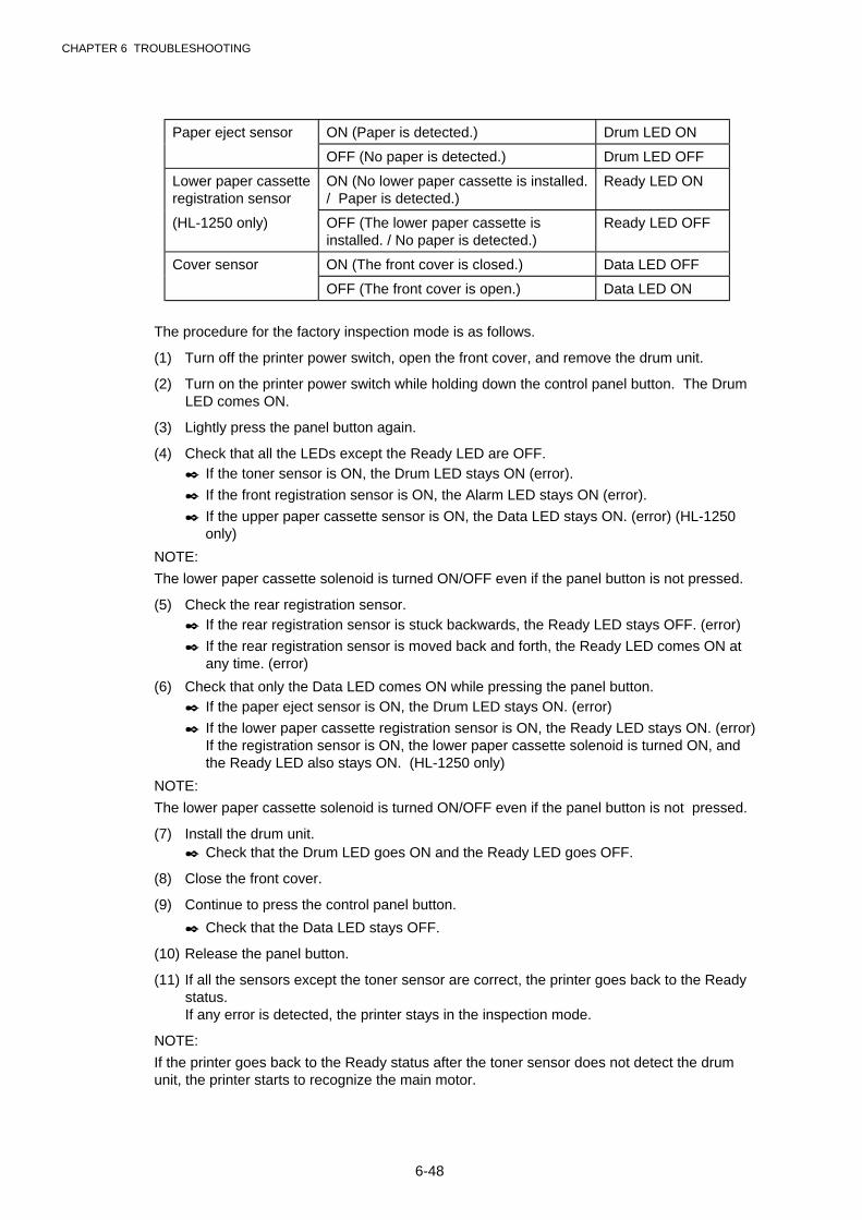
CHAPTER 6 TROUBLESHOOTING
6-48
Paper eject sensor ON (Paper is detected.) Drum LED ON
OFF (No paper is detected.) Drum LED OFF
Lower paper cassetteregistration sensor
ON (No lower paper cassette is installed./ Paper is detected.)
Ready LED ON
(HL-1250 only) OFF (The lower paper cassette isinstalled. / No paper is detected.)
Ready LED OFF
Cover sensor ON (The front cover is closed.) Data LED OFF
OFF (The front cover is open.) Data LED ON
The procedure for the factory inspection mode is as follows.
(1) Turn off the printer power switch, open the front cover, and remove the drum unit.
(2) Turn on the printer power switch while holding down the control panel button. The DrumLED comes ON.
(3) Lightly press the panel button again.
(4) Check that all the LEDs except the Ready LED are OFF.✒ If the toner sensor is ON, the Drum LED stays ON (error).
✒ If the front registration sensor is ON, the Alarm LED stays ON (error).
✒ If the upper paper cassette sensor is ON, the Data LED stays ON. (error) (HL-1250only)
NOTE:
The lower paper cassette solenoid is turned ON/OFF even if the panel button is not pressed.
(5) Check the rear registration sensor.✒ If the rear registration sensor is stuck backwards, the Ready LED stays OFF. (error)
✒ If the rear registration sensor is moved back and forth, the Ready LED comes ON atany time. (error)
(6) Check that only the Data LED comes ON while pressing the panel button.✒ If the paper eject sensor is ON, the Drum LED stays ON. (error)
✒ If the lower paper cassette registration sensor is ON, the Ready LED stays ON. (error)If the registration sensor is ON, the lower paper cassette solenoid is turned ON, andthe Ready LED also stays ON. (HL-1250 only)
NOTE:
The lower paper cassette solenoid is turned ON/OFF even if the panel button is not pressed.
(7) Install the drum unit.✒ Check that the Drum LED goes ON and the Ready LED goes OFF.
(8) Close the front cover.
(9) Continue to press the control panel button.
✒ Check that the Data LED stays OFF.
(10) Release the panel button.
(11) If all the sensors except the toner sensor are correct, the printer goes back to the Readystatus.If any error is detected, the printer stays in the inspection mode.
NOTE:
If the printer goes back to the Ready status after the toner sensor does not detect the drumunit, the printer starts to recognize the main motor.

APPENDIX
A-1
APPENDIX 1. SERIAL NO. DESCRIPTIONS
The descriptions below show how to understand the meanings of the numbers printed on thelabels or bag of the printer and printer parts.
< ID for production month >
A: January B: February C: March D: AprilE: May F: June G: July H: AugustJ: September K: October L: November M: December
< ID for factory >
9: Kariya Plant A: Mie Brother C: BIUKJ: Buji Nan Ling Factory
(1) Printer ..................printed on the label attached on the rear of the main body
X X X X X X G 9 J 1 1 1 1 0 1
(2) Process unit ........ imprinted on the aluminum bag
(Drum unit with toner cartridge)
9 F 3 0 J
(3) Drum unit .............printed on the bar code label attached inside the drum unit
F 9 9 1 0 0 1 0 4
YEARMONTH
DATE
FACTORY ID NO.
YEARMONTH
SERIAL NO.
<MODEL NO.>
MONTH
YEARFACTORY ID NO.
SEQUENTIAL NO.
< SERIAL NO. >
FACTORY ID NO.
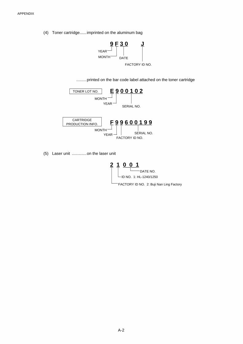
APPENDIX
A-2
(4) Toner cartridge...... imprinted on the aluminum bag
9 F 3 0 J
.........printed on the bar code label attached on the toner cartridge
E 9 0 0 1 0 2
F 9 9 6 0 0 1 9 9
(5) Laser unit .............on the laser unit
2 1 0 0 1
YEAR
MONTH DATE
FACTORY ID NO.
YEAR
YEAR
MONTH
MONTH
TONER LOT NO.
SERIAL NO.
SERIAL NO.
DATE NO.
ID NO. 1: HL-1240/1250
FACTORY ID NO. 2: Buji Nan Ling Factory
FACTORY ID NO.
CARTRIDGEPRODUCTION INFO.
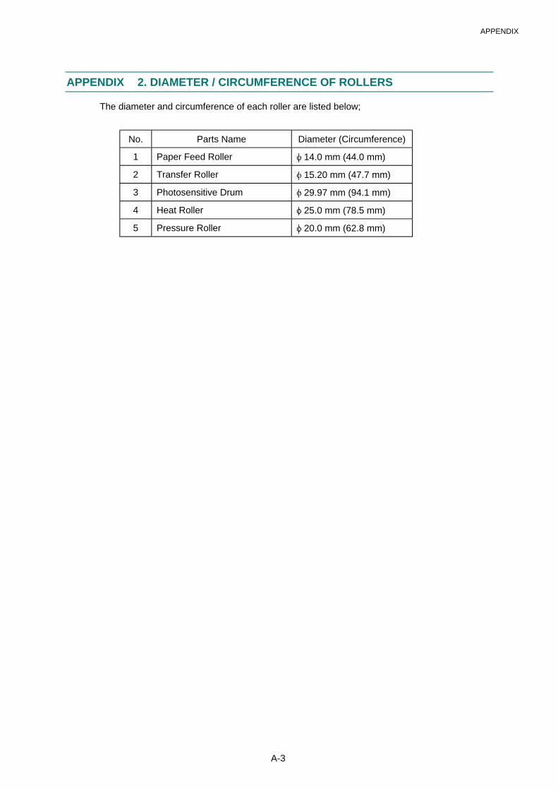
APPENDIX
A-3
APPENDIX 2. DIAMETER / CIRCUMFERENCE OF ROLLERS
The diameter and circumference of each roller are listed below;
No. Parts Name Diameter (Circumference)
1 Paper Feed Roller � 14.0 mm (44.0 mm)
2 Transfer Roller � 15.20 mm (47.7 mm)
3 Photosensitive Drum � 29.97 mm (94.1 mm)
4 Heat Roller � 25.0 mm (78.5 mm)
5 Pressure Roller � 20.0 mm (62.8 mm)
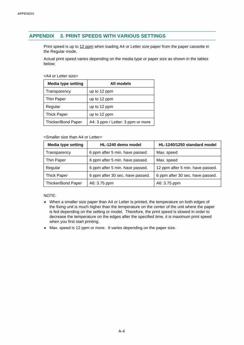
APPENDIX
A-4
APPENDIX 3. PRINT SPEEDS WITH VARIOUS SETTINGS
Print speed is up to 12 ppm when loading A4 or Letter size paper from the paper cassette inthe Regular mode.
Actual print speed varies depending on the media type or paper size as shown in the tablesbelow;
<A4 or Letter size>
Media type setting All models
Transparency up to 12 ppm
Thin Paper up to 12 ppm
Regular up to 12 ppm
Thick Paper up to 12 ppm
Thicker/Bond Paper A4: 3 ppm / Letter: 3 ppm or more
<Smaller size than A4 or Letter>
Media type setting HL-1240 demo model HL-1240/1250 standard model
Transparency 6 ppm after 5 min. have passed. Max. speed
Thin Paper 6 ppm after 5 min. have passed. Max. speed
Regular 6 ppm after 5 min. have passed. 12 ppm after 5 min. have passed.
Thick Paper 6 ppm after 30 sec. have passed. 6 ppm after 30 sec. have passed.
Thicker/Bond Paper A6: 3.75 ppm A6: 3.75 ppm
NOTE:
� When a smaller size paper than A4 or Letter is printed, the temperature on both edges ofthe fixing unit is much higher than the temperature on the center of the unit where the paperis fed depending on the setting or model. Therefore, the print speed is slowed in order todecrease the temperature on the edges after the specified time, it is maximum print speedwhen you first start printing.
� Max. speed is 12 ppm or more. It varies depending on the paper size.
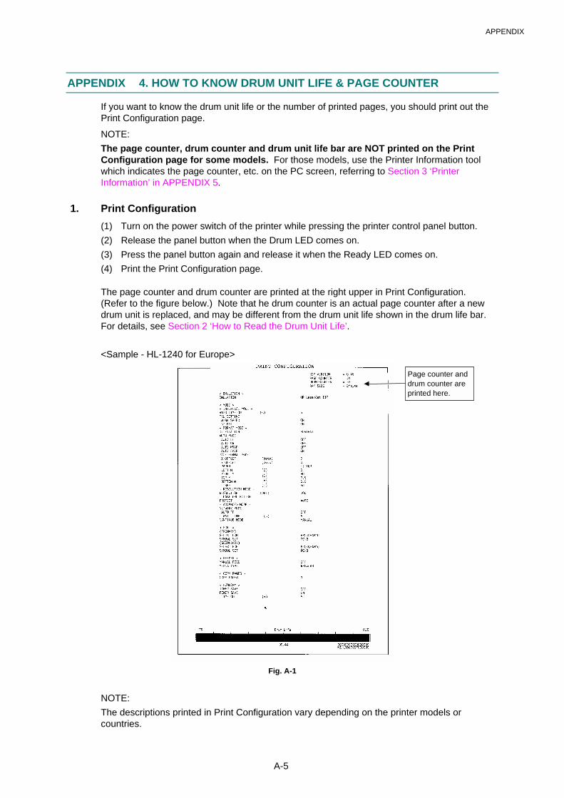
APPENDIX
A-5
APPENDIX 4. HOW TO KNOW DRUM UNIT LIFE & PAGE COUNTER
If you want to know the drum unit life or the number of printed pages, you should print out thePrint Configuration page.
NOTE:
The page counter, drum counter and drum unit life bar are NOT printed on the PrintConfiguration page for some models. For those models, use the Printer Information toolwhich indicates the page counter, etc. on the PC screen, referring to Section 3 ‘PrinterInformation’ in APPENDIX 5.
1. Print Configuration
(1) Turn on the power switch of the printer while pressing the printer control panel button.
(2) Release the panel button when the Drum LED comes on.
(3) Press the panel button again and release it when the Ready LED comes on.
(4) Print the Print Configuration page.
The page counter and drum counter are printed at the right upper in Print Configuration.(Refer to the figure below.) Note that he drum counter is an actual page counter after a newdrum unit is replaced, and may be different from the drum unit life shown in the drum life bar.For details, see Section 2 ‘How to Read the Drum Unit Life’.
<Sample - HL-1240 for Europe>
Fig. A-1
NOTE:
The descriptions printed in Print Configuration vary depending on the printer models orcountries.
Page counter anddrum counter areprinted here.
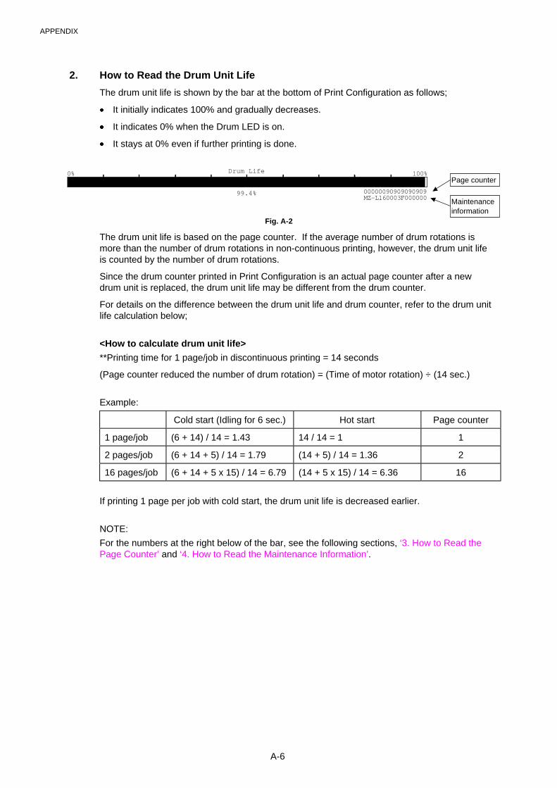
APPENDIX
A-6
2. How to Read the Drum Unit Life
The drum unit life is shown by the bar at the bottom of Print Configuration as follows;
� It initially indicates 100% and gradually decreases.
� It indicates 0% when the Drum LED is on.
� It stays at 0% even if further printing is done.
Drum Life
00000090909090909
100%0%
99.4%MZ-L160003F000000
Fig. A-2
The drum unit life is based on the page counter. If the average number of drum rotations ismore than the number of drum rotations in non-continuous printing, however, the drum unit lifeis counted by the number of drum rotations.
Since the drum counter printed in Print Configuration is an actual page counter after a newdrum unit is replaced, the drum unit life may be different from the drum counter.
For details on the difference between the drum unit life and drum counter, refer to the drum unitlife calculation below;
<How to calculate drum unit life>
**Printing time for 1 page/job in discontinuous printing = 14 seconds
(Page counter reduced the number of drum rotation) = (Time of motor rotation) ÷ (14 sec.)
Example:
Cold start (Idling for 6 sec.) Hot start Page counter
1 page/job (6 + 14) / 14 = 1.43 14 / 14 = 1 1
2 pages/job (6 + 14 + 5) / 14 = 1.79 (14 + 5) / 14 = 1.36 2
16 pages/job (6 + 14 + 5 x 15) / 14 = 6.79 (14 + 5 x 15) / 14 = 6.36 16
If printing 1 page per job with cold start, the drum unit life is decreased earlier.
NOTE:
For the numbers at the right below of the bar, see the following sections, ‘3. How to Read thePage Counter’ and ‘4. How to Read the Maintenance Information’.
Page counter
Maintenanceinformation
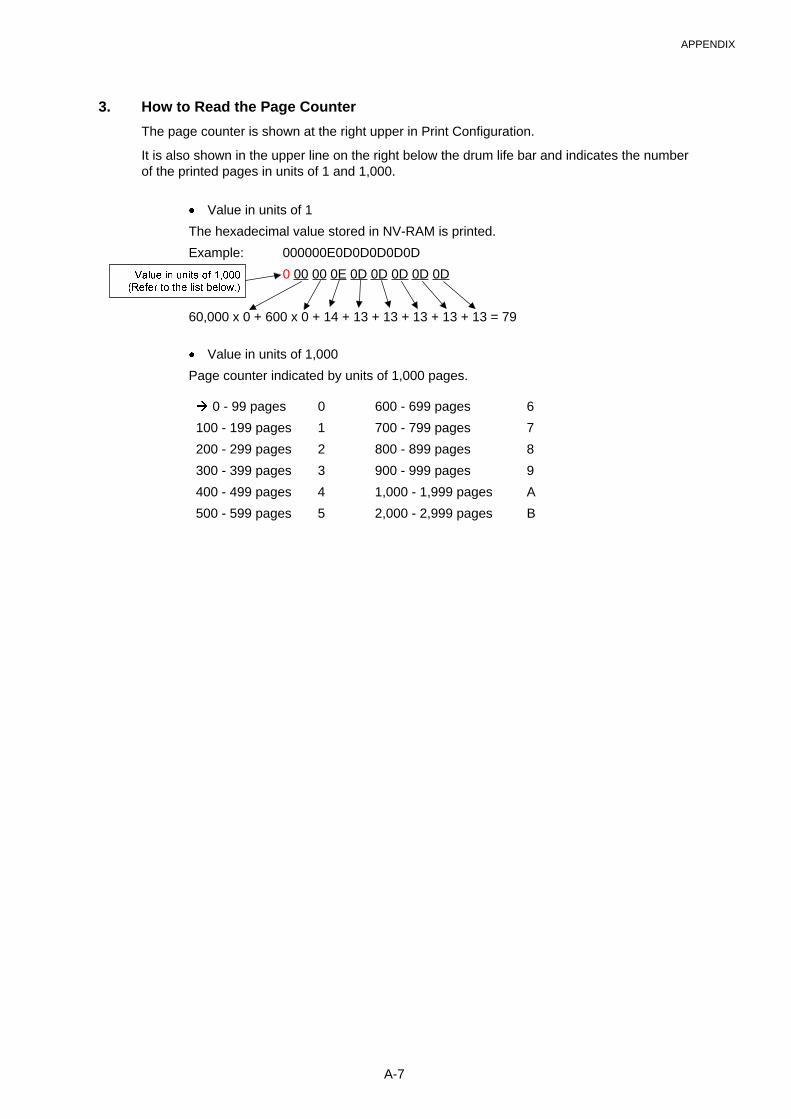
APPENDIX
A-7
3. How to Read the Page Counter
The page counter is shown at the right upper in Print Configuration.
It is also shown in the upper line on the right below the drum life bar and indicates the numberof the printed pages in units of 1 and 1,000.
� Value in units of 1
The hexadecimal value stored in NV-RAM is printed.
Example: 000000E0D0D0D0D0D
0 00 00 0E 0D 0D 0D 0D 0D
60,000 x 0 + 600 x 0 + 14 + 13 + 13 + 13 + 13 + 13 = 79
� Value in units of 1,000
Page counter indicated by units of 1,000 pages.
� 0 - 99 pages 0 600 - 699 pages 6
100 - 199 pages 1 700 - 799 pages 7
200 - 299 pages 2 800 - 899 pages 8
300 - 399 pages 3 900 - 999 pages 9
400 - 499 pages 4 1,000 - 1,999 pages A
500 - 599 pages 5 2,000 - 2,999 pages B
����� �� ��� �� ����
������ � �� �� �������
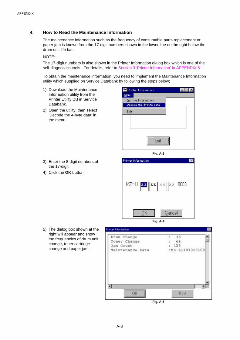
APPENDIX
A-8
4. How to Read the Maintenance Information
The maintenance information such as the frequency of consumable parts replacement orpaper jam is known from the 17-digit numbers shown in the lower line on the right below thedrum unit life bar.
NOTE:
The 17-digit numbers is also shown in the Printer Information dialog box which is one of theself-diagnostics tools. For details, refer to Section 3 ‘Printer Information’ in APPENDIX 5.
To obtain the maintenance information, you need to implement the Maintenance Informationutility which supplied on Service Databank by following the steps below;
1) Download the MaintenanceInformation utility from thePrinter Utility DB in ServiceDatabank.
2) Open the utility, then select‘Decode the 4-byte data’ inthe menu.
Fig. A-3
3) Enter the 8-digit numbers ofthe 17-digit.
4) Click the OK button.
Fig. A-4
5) The dialog box shown at theright will appear and showthe frequencies of drum unitchange, toner cartridgechange and paper jam.
Fig. A-5
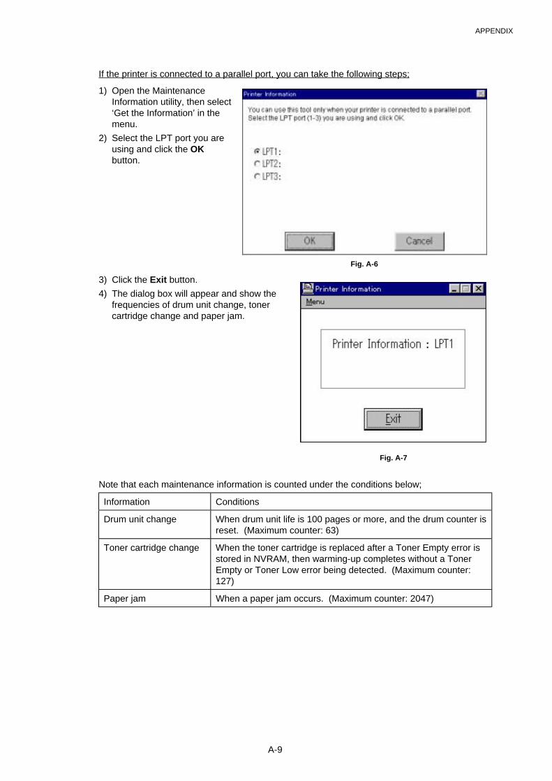
APPENDIX
A-9
If the printer is connected to a parallel port, you can take the following steps;
1) Open the MaintenanceInformation utility, then select‘Get the Information’ in themenu.
2) Select the LPT port you areusing and click the OKbutton.
Fig. A-6
3) Click the Exit button.
4) The dialog box will appear and show thefrequencies of drum unit change, tonercartridge change and paper jam.
Fig. A-7
Note that each maintenance information is counted under the conditions below;
Information Conditions
Drum unit change When drum unit life is 100 pages or more, and the drum counter isreset. (Maximum counter: 63)
Toner cartridge change When the toner cartridge is replaced after a Toner Empty error isstored in NVRAM, then warming-up completes without a TonerEmpty or Toner Low error being detected. (Maximum counter:127)
Paper jam When a paper jam occurs. (Maximum counter: 2047)
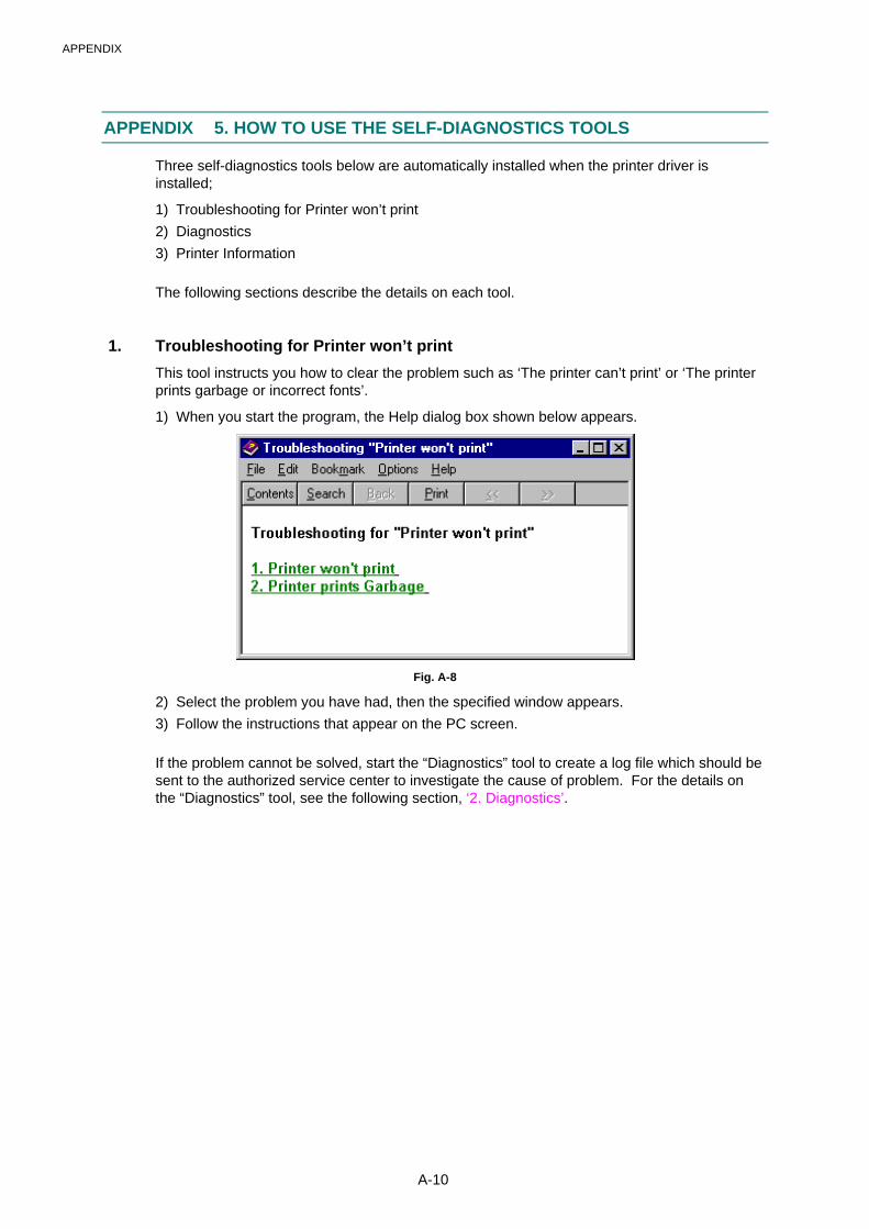
APPENDIX
A-10
APPENDIX 5. HOW TO USE THE SELF-DIAGNOSTICS TOOLS
Three self-diagnostics tools below are automatically installed when the printer driver isinstalled;
1) Troubleshooting for Printer won’t print
2) Diagnostics
3) Printer Information
The following sections describe the details on each tool.
1. Troubleshooting for Printer won’t print
This tool instructs you how to clear the problem such as ‘The printer can’t print’ or ‘The printerprints garbage or incorrect fonts’.
1) When you start the program, the Help dialog box shown below appears.
Fig. A-8
2) Select the problem you have had, then the specified window appears.
3) Follow the instructions that appear on the PC screen.
If the problem cannot be solved, start the “Diagnostics” tool to create a log file which should besent to the authorized service center to investigate the cause of problem. For the details onthe “Diagnostics” tool, see the following section, ‘2. Diagnostics’.
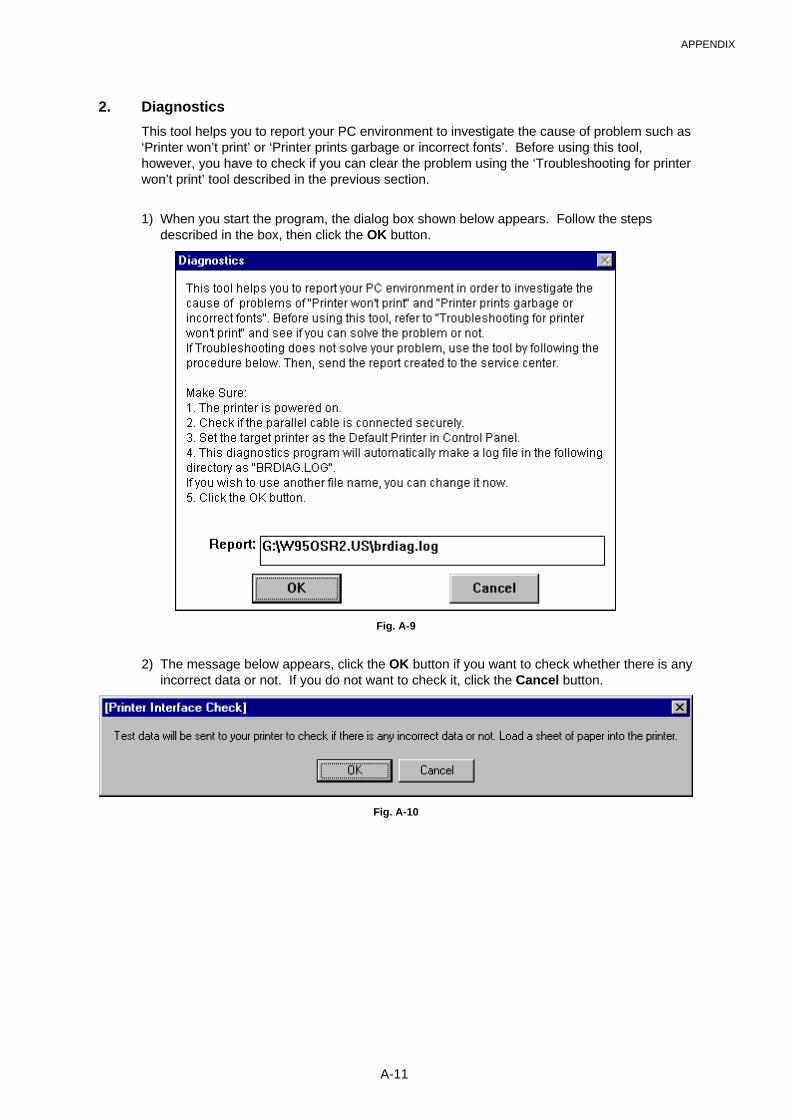
APPENDIX
A-11
2. Diagnostics
This tool helps you to report your PC environment to investigate the cause of problem such as‘Printer won’t print’ or ‘Printer prints garbage or incorrect fonts’. Before using this tool,however, you have to check if you can clear the problem using the ‘Troubleshooting for printerwon’t print’ tool described in the previous section.
1) When you start the program, the dialog box shown below appears. Follow the stepsdescribed in the box, then click the OK button.
Fig. A-9
2) The message below appears, click the OK button if you want to check whether there is anyincorrect data or not. If you do not want to check it, click the Cancel button.
Fig. A-10
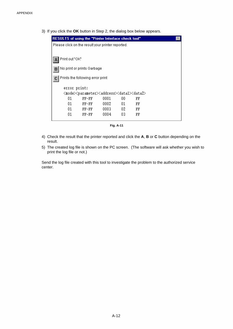
APPENDIX
A-12
3) If you click the OK button in Step 2, the dialog box below appears.
Fig. A-11
4) Check the result that the printer reported and click the A, B or C button depending on theresult.
5) The created log file is shown on the PC screen. (The software will ask whether you wish toprint the log file or not.)
Send the log file created with this tool to investigate the problem to the authorized servicecenter.
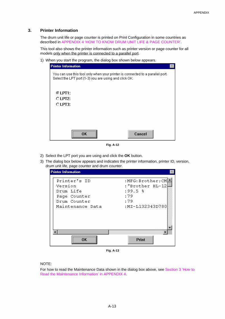
APPENDIX
A-13
3. Printer Information
The drum unit life or page counter is printed on Print Configuration in some countries asdescribed in APPENDIX 4 ‘HOW TO KNOW DRUM UNIT LIFE & PAGE COUNTER’.
This tool also shows the printer information such as printer version or page counter for allmodels only when the printer is connected to a parallel port.
1) When you start the program, the dialog box shown below appears.
Fig. A-12
2) Select the LPT port you are using and click the OK button.
3) The dialog box below appears and indicates the printer information, printer ID, version,drum unit life, page counter and drum counter.
Fig. A-13
NOTE:
For how to read the Maintenance Data shown in the dialog box above, see Section 3 ‘How toRead the Maintenance Information’ in APPENDIX 4.
APPENDIX
A-14
APPENDIX 6. NVRAM DEFAULT VALUE
The default values for the main items to be set in NVRAM are as follows;
Items Descriptions
Timing of Drum LED ON 16,000 page
(Counted from the drum unit life.)
Development switchingtiming
The developing bias is switched from 475V to 375V when3,000 pages are printed.
(Counted from the number of the drum rotation in non-continuous printing)
Fixing temperature � Transparency: 163°C
� Thin paper: 183°C� Regular paper: 195°C� Thick paper: 215°C� Thicker/Bond paper: 215°C (in non-continuous printing)
Smaller size mode See APPENDIX 3 ‘PRINT SPEEDS WITH VARIOUSSETTINGS’.
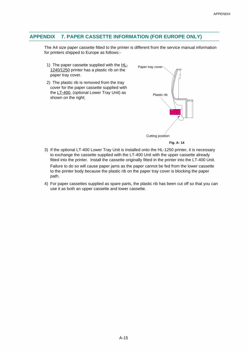
APPENDIX
A-15
APPENDIX 7. PAPER CASSETTE INFORMATION (FOR EUROPE ONLY)
The A4 size paper cassette fitted to the printer is different from the service manual informationfor printers shipped to Europe as follows:-
1) The paper cassette supplied with the HL-1240/1250 printer has a plastic rib on thepaper tray cover.
2) The plastic rib is removed from the traycover for the paper cassette supplied withthe LT-400, (optional Lower Tray Unit) asshown on the right;
Fig. A- 14
3) If the optional LT-400 Lower Tray Unit is installed onto the HL-1250 printer, it is necessaryto exchange the cassette supplied with the LT-400 Unit with the upper cassette alreadyfitted into the printer. Install the cassette originally fitted in the printer into the LT-400 Unit.
Failure to do so will cause paper jams as the paper cannot be fed from the lower cassetteto the printer body because the plastic rib on the paper tray cover is blocking the paperpath.
4) For paper cassettes supplied as spare parts, the plastic rib has been cut off so that you canuse it as both an upper cassette and lower cassette.
Cutting position
Plastic rib
Paper tray cover
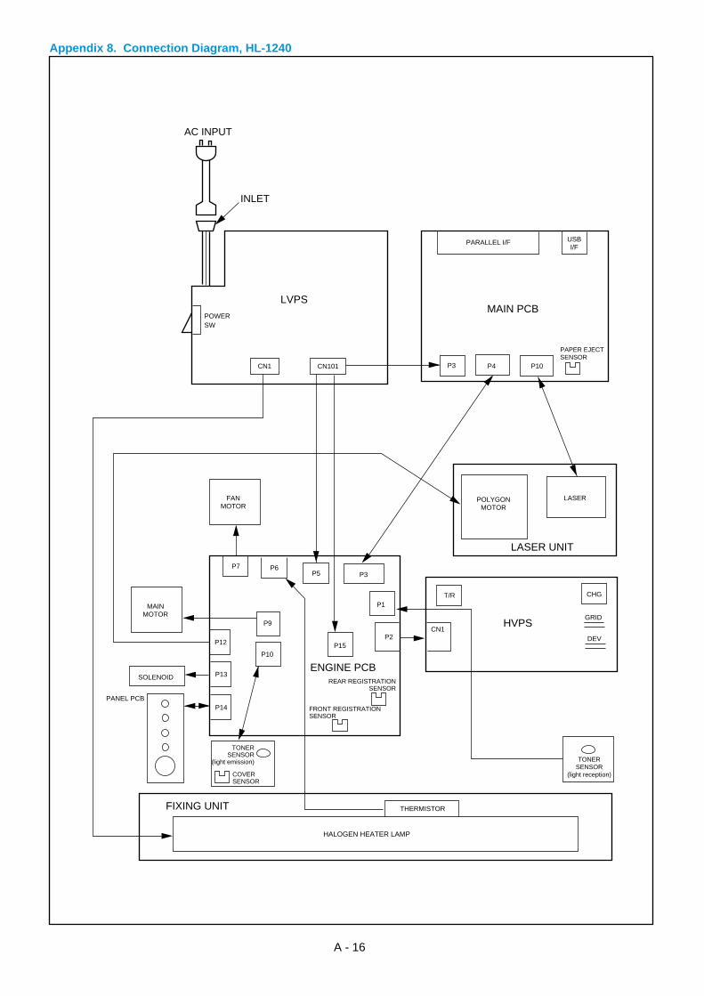
Appendix 8. Connection Diagram, HL-1240
A - 16
THERMISTOR
HALOGEN HEATER LAMP
LVPSPOWERSW
INLET
AC INPUT
CN1 CN101
PARALLEL I/F
MAIN PCB
HVPS
LASER UNIT
USBI/F
P10P3 P4
POLYGONMOTOR
LASER
T/R CHG
GRID
DEVCN1
SOLENOID
TONERSENSOR
(light reception)
FANMOTOR
TONERSENSOR
(light emission)
COVERSENSOR
MAINMOTOR
P7 P6P5 P3
P9
P10P15
P2
P1
P12
P13
P14
REAR REGISTRATIONSENSOR
FRONT REGISTRATIONSENSOR
PANEL PCB
PAPER EJECTSENSOR
ENGINE PCB
FIXING UNIT
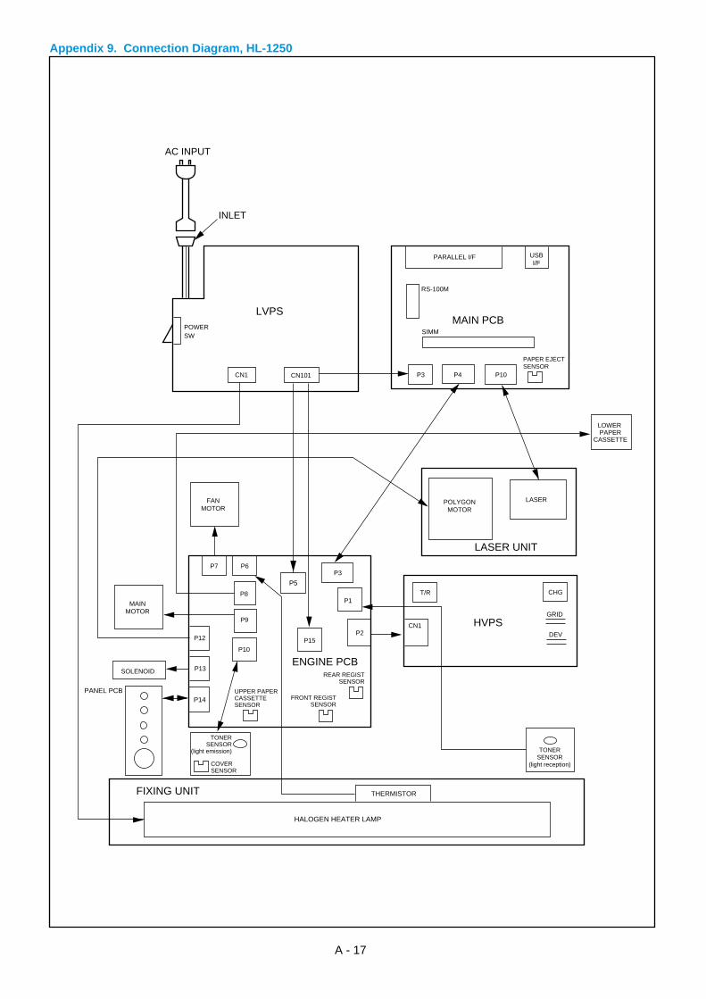
Appendix 9. Connection Diagram, HL-1250
A - 17
LVPSPOWERSW
INLET
AC INPUT
CN1 CN101
PARALLEL I/F
MAIN PCB
HVPS
LASER UNIT
USBI/F
P10P3 P4
POLYGONMOTOR
LASER
T/R CHG
GRID
DEVCN1
SOLENOID
TONERSENSOR
(light reception)
FANMOTOR
TONERSENSOR
(light emission)
COVERSENSOR
MAINMOTOR
P7 P6P3
P8
P9
P10P15
P2
P1
P12
P13REAR REGIST
SENSOR
FRONT REGISTSENSOR
UPPER PAPERCASSETTESENSOR
PAPER EJECTSENSOR
LOWER PAPER
CASSETTE
ENGINE PCB
THERMISTOR
HALOGEN HEATER LAMP
FIXING UNIT
SIMM
RS-100M
P5
P14PANEL PCB
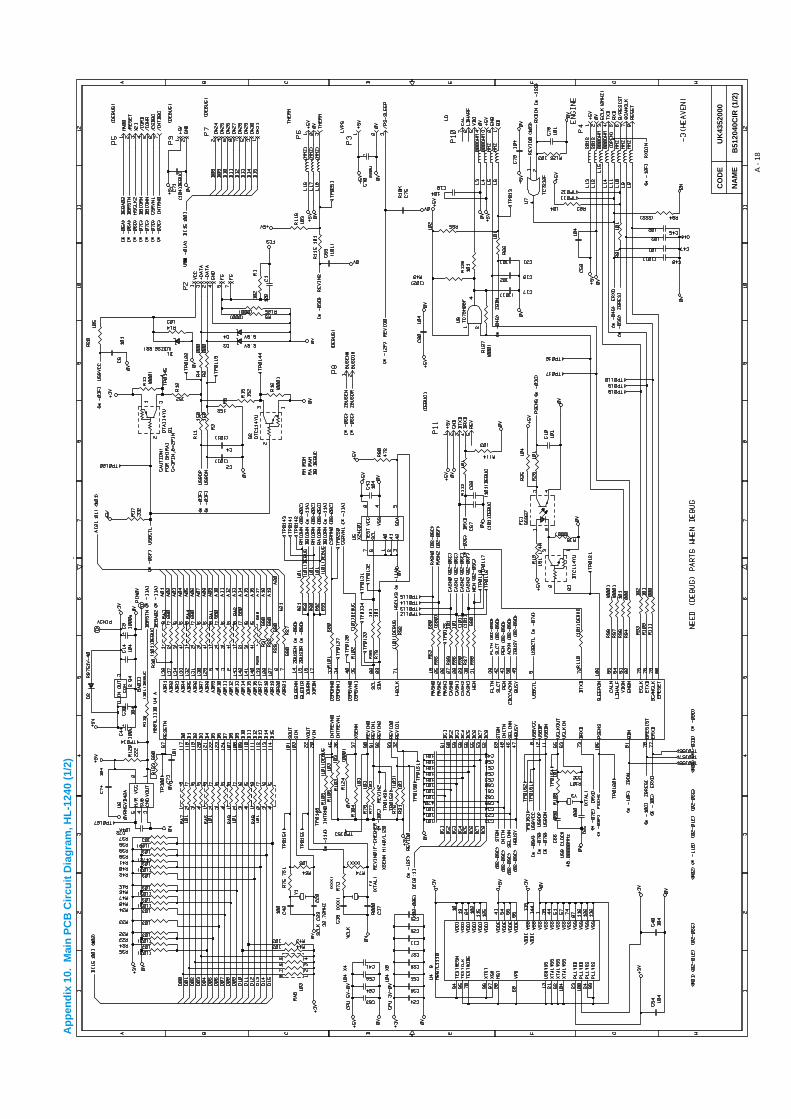
CO
DE
UK
4352
000
B51
2040
CIR
(1/
2)
A -
18
NA
ME
Ap
pen
dix
10.
Mai
n P
CB
Cir
cuit
Dia
gra
m, H
L-1
240
(1/2
)

Ap
pen
dix
11.
Mai
n P
CB
Cir
cuit
Dia
gra
m, H
L-1
240
(2/2
)
CO
DE
UK
4352
000
B51
2040
CIR
(2/
2)
A -
19
NA
ME
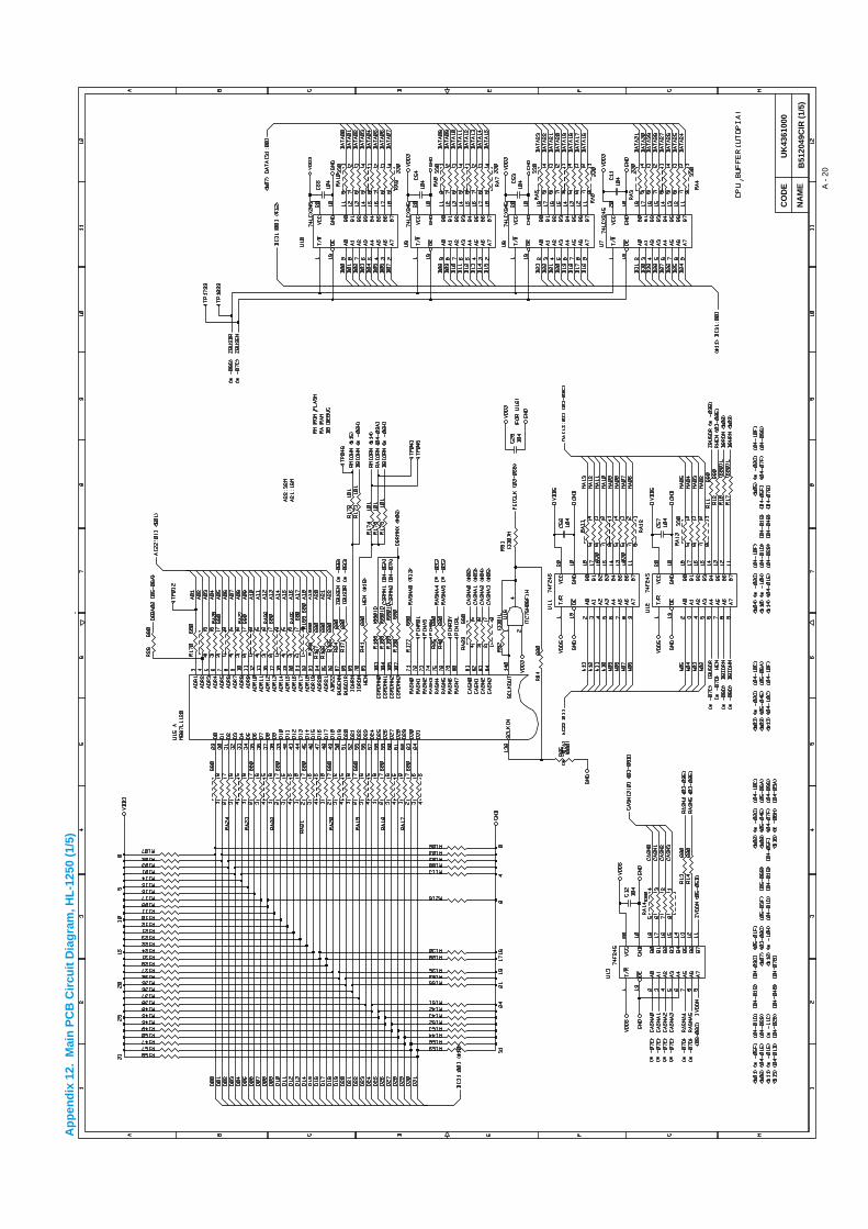
Ap
pen
dix
12.
Mai
n P
CB
Cir
cuit
Dia
gra
m, H
L-1
250
(1/5
)
CO
DE
UK
4361
000
B51
2049
CIR
(1/
5)
A -
20
NA
ME
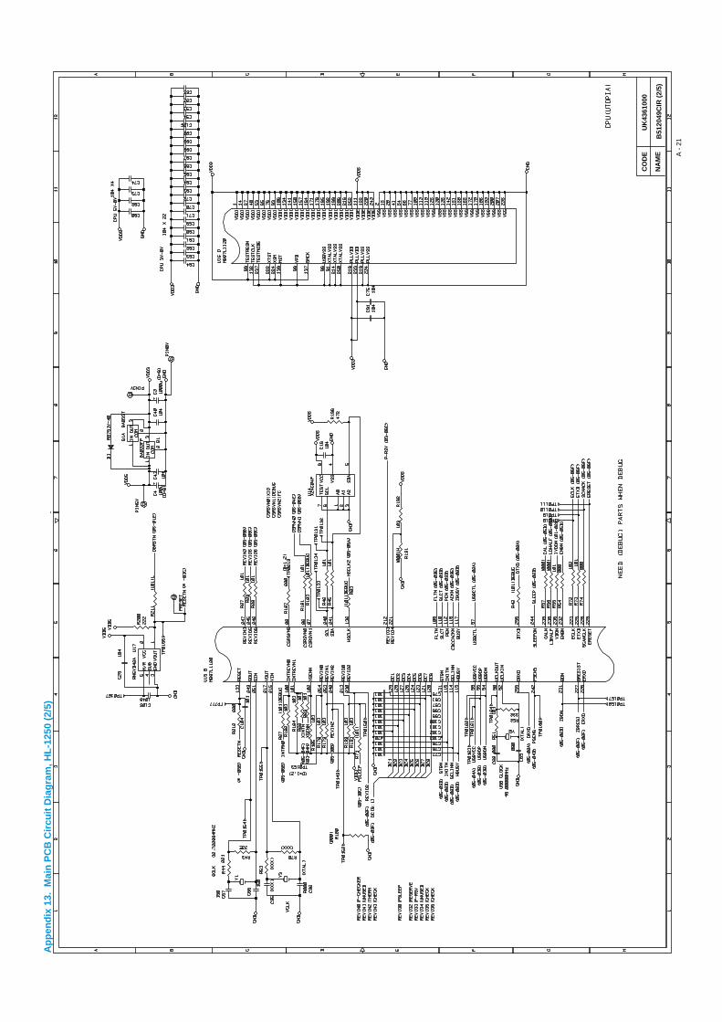
Ap
pen
dix
13.
Mai
n P
CB
Cir
cuit
Dia
gra
m, H
L-1
250
(2/5
)
CO
DE
UK
4361
000
B51
2049
CIR
(2/
5)
A -
21
NA
ME

CO
DE
UK
4361
000
B51
2049
CIR
A -
22
NA
ME
Ap
pen
dix
14.
Mai
n P
CB
Cir
cuit
Dia
gra
m, H
L-1
250
(3/5
)
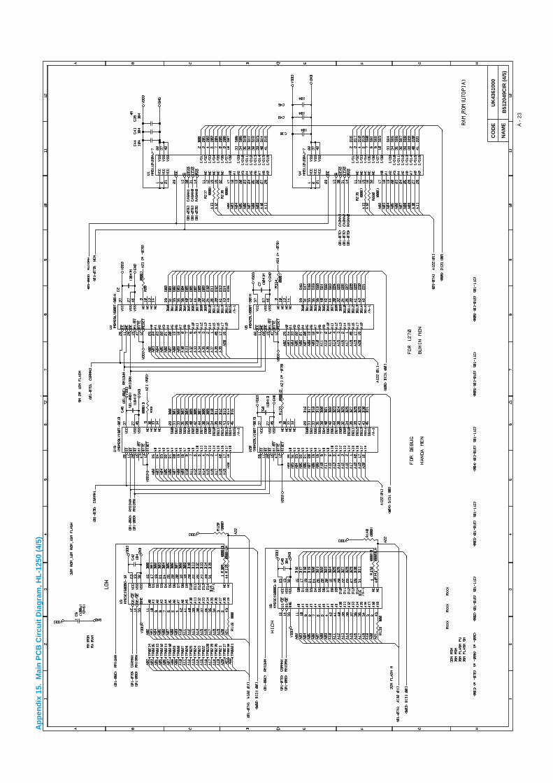
CO
DE
UK
4361
000
B51
2049
CIR
(4/
5)
A -
23
NA
ME
Ap
pen
dix
15.
Mai
n P
CB
Cir
cuit
Dia
gra
m, H
L-1
250
(4/5
)

CO
DE
UK
4361
000
B51
2049
CIR
(5/
5)
A -
24
NA
ME
Ap
pen
dix
16.
Mai
n P
CB
Cir
cuit
Dia
gra
m, H
L-1
250
(5/5
)
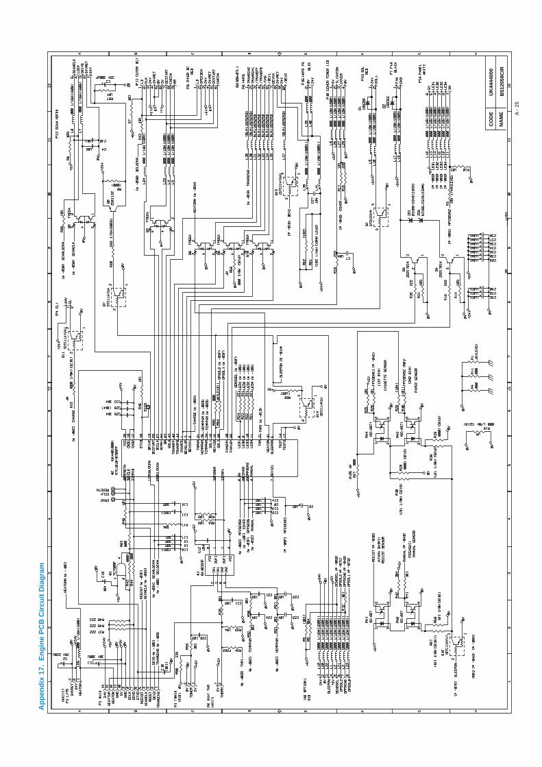
Ap
pen
dix
17.
En
gin
e P
CB
Cir
cuit
Dia
gra
m
CO
DE
UK
4444
000
B51
2059
CIR
A -
25
NA
ME
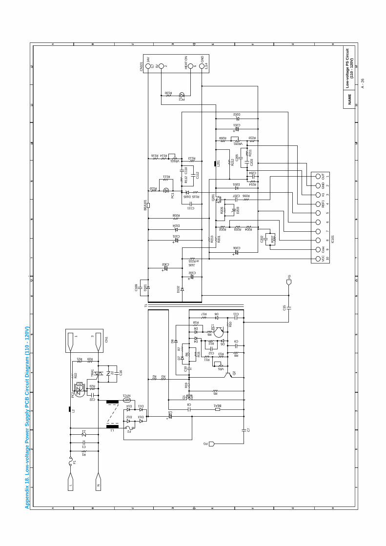
Lo
w-v
olt
age
PS
Cir
cuit
(110
- 1
20V
)
A -
26
NA
ME
Ap
pen
dix
18.
Lo
w-v
olt
age
Po
wer
Su
pp
ly P
CB
Cir
cuit
Dia
gra
m (
110
- 12
0V)
+
+
+
+
+
+
R1
F2
D12 D13
C5
C8
R5
D4
R11
C12 R13
R12
R9
R17
C302
C101
C206
D104
R208
R202
C207
D201 R214
C204
R209
VR201
C201
D202
R210
R206
R203 R204
R110
R111
R116
R130
PC2
R114
VR101R113
C111
D105 R115
C102
J105or R215
D6 C11
D5
R8
C9
VR1
D9
R18
R2 R3
FG
BEA1D14
NTC1
D11
C1
Z1 L1
C22
R23
R21 R20
NLF1
L2R
22
CN
1
PC
2
TRA
1
Z2 C16
T1
C10
9
D10
1B
EA
101
PC
1
R11
2
R21
3
R20
5
Q20
1
R21
2
L201
D20
3C
205
C20
3R
211
R20
1
C20
2
R20
7
IC10
1
VC
C10
Cos
c9
5R
EF1 4
K1 3
GN
D2
OU
T1
87
6
C11
0
C11
2
CN
101 24
V
5V 2 6
GN
D1,
3,4
5,7
HE
AT
ON
D10
2
C7
Q1
R19
D8
C10
Q2
FG
D7
R7
R6
R15
R10
C15
PC
1
1 3
ZC
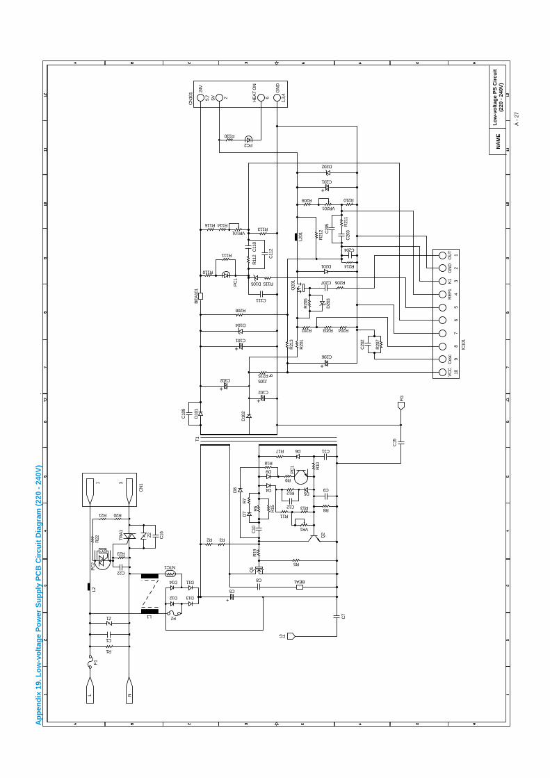
Lo
w-v
olt
age
PS
Cir
cuit
(220
- 2
40V
)
A -
27
NA
ME
Ap
pen
dix
19.
Lo
w-v
olt
age
Po
wer
Su
pp
ly P
CB
Cir
cuit
Dia
gra
m (
220
- 24
0V)
+
+
+
+
+
+
R1
F2
D12 D13
C5
C8
R5
D4
R11
C12 R13
R12
R9
R17
C302
C101
C206
D104
R208
R202
C207
D201 R214
C204
R209
VR201
C201
D202
R210
R206
R203 R204
R110
R111
R116
R130
PC2
R114
VR101R113
C111
D105 R115
C102
J105or R215
D6 C11
D5
R8
C9
VR1
D9
R18
R2 R3
FG
BEA1D14
NTC1
D11
C1
Z1 L1
C22
R23
R21 R20
NLF1
L2R
22
CN
1
PC
2
TRA
1
Z2 C16
T1
C10
9
D10
1B
EA
101
PC
1
R11
2
R21
3
R20
5
Q20
1
R21
2
L201
D20
3C
205
C20
3R
211
R20
1
C20
2
R20
7
IC10
1
VC
C10
Cos
c9
5R
EF1 4
K1 3
GN
D2
OU
T1
87
6
C11
0
C11
2
CN
101 24
V
5V 2 6
GN
D1,
3,4
5,7
HE
AT
ON
D10
2
C7
Q1
R19
D8
C10
Q2
FG
D7
R7
R6
R15
R10
C15
PC
1
1 3
ZC
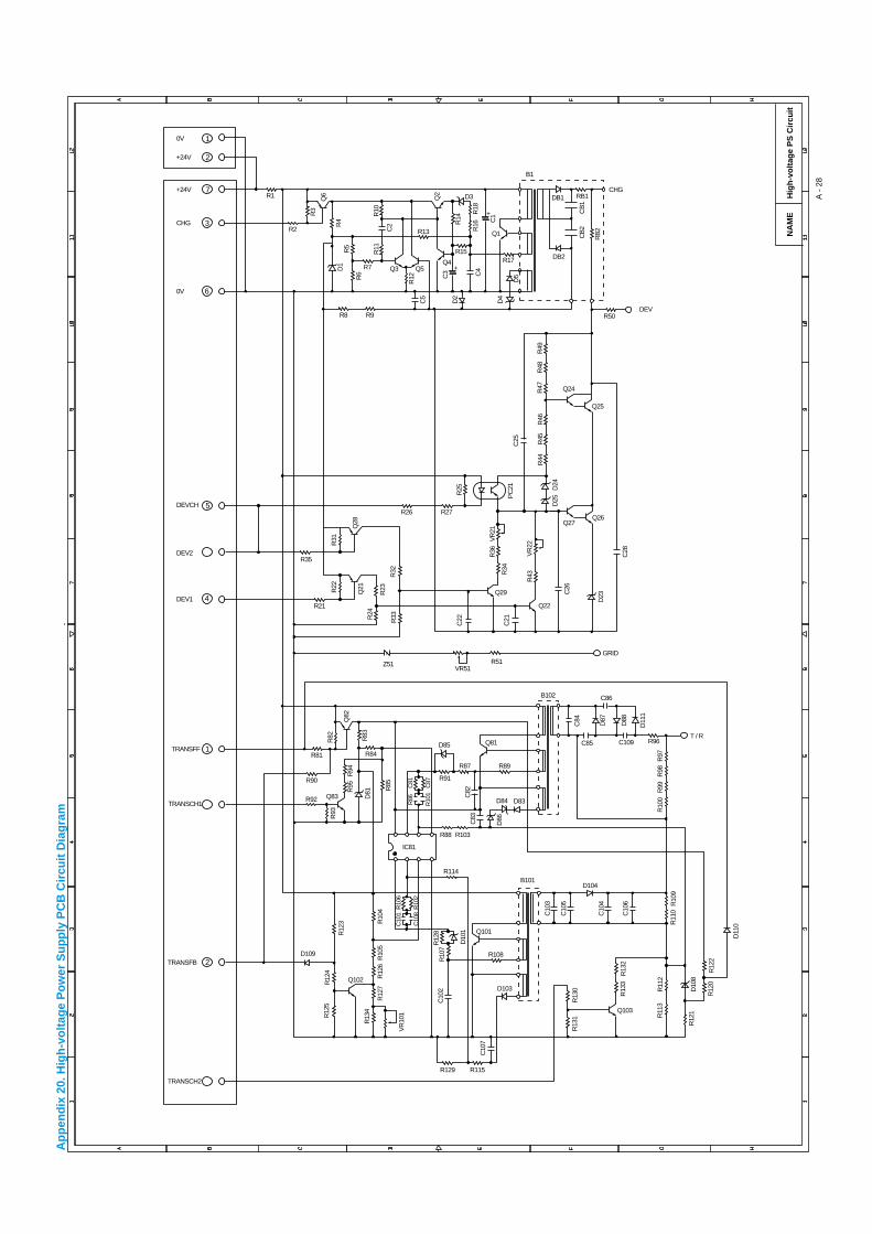
Hig
h-v
olt
age
PS
Cir
cuit
A -
28
NA
ME
Ap
pen
dix
20.
Hig
h-v
olt
age
Po
wer
Su
pp
ly P
CB
Cir
cuit
Dia
gra
m
2
1
5
4
6
3
7
TRANSFB
TRANSCH2
TRANSFF
TRANSCH1
R81
R90
R92 Q83
R89
R108
IC81
Q81
B102
Q29
R27R26
R17R15
R13
R7
R9R8
R2
R1
Q4Q5Q3
Q1
DB2
DB1
B1
RB1
R21
R35
VR51R51
GRID
Z51
C86
DEVR50
CHG
T / R
B101
D109
Q102
Q101
D103
R115R129
D104
R88 R103
R114
R84
R83
R85
R10
2C
108
R10
6C
101
R10
4
R12
3
R12
4R
125
R12
6R
127
VR
101
R13
4
R10
5
R82
D81R
95R
94
R93
Q82
C82
R24
R23
R34
R36
VR
21
Q22
R43
VR
22
RB
2
CB
2C
B1
R25
R18
R16
R12
R11R5
R6
R4
R3
R10
R14
R22
R31
Q21
D84 D83
C84
C109 R96C85
D87
D88
D11
1
R10
0R
99R
98R
97
C83
D86
C10
3
C10
5
C10
4
C10
6
C10
2
C10
7
R10
7R
128
D10
1
R10
9R
110
R11
2
D10
8
D11
0
R11
3
R12
1
DEVCH
DEV2
DEV1
0V
CHG
+24V
2
1
+24V
0V
C22
C21
C26
D25
D24
R44
R45
R46
R47
R48
R49
PC
21
D23
C28
C4
C1
C3
+
D5
D4
D2
D3Q2
C5
C2
D1
Q6
+
Q25
Q24
Q26Q27
C25
R33
Q28
R32
R91
D85
R87
C87
R10
1
C81
R86
R12
2R
120
R13
2R
133
Q103
R13
0R
131
INDEX
i
INDEX
3
3 patterns print mode ..............................6-46
4
4% density pattern print mode.................6-46
A
AC cord .....................................................4-3AC inlet ASSY .........................................4-27AC power inlet ...........................................1-3address error ...........................................6-22Advanced Photoscale Technology ............1-2Alarm LED ...............................................2-14all black....................................................6-27APT............................................................1-2ASIC ..........................................................3-5
B
bar code ....................................................1-2base plate................................................4-25BD failure.................................................6-20black band ...............................................6-36black horizontal stripes............................6-30black spots ..............................................6-36black vertical streaks ...............................6-29black vertical streaks (in a gray background)
.............................................................6-30blurred horizontal stripes .........................6-30blurred vertical streaks ............................6-29BUS error ................................................6-22
C
cassette cover film.....................................4-5cassette pressure roller ..................3-17, 4-6circumference........................................... A-3cleaner.....................................................3-21cleaner spring..........................................4-22cleaning .....................................................5-5completely blank......................................6-26component.................................................2-2condensation .............................................6-1connection diagram ......................... A-16 - 17
consumable parts .............................. 5-1, 6-1continuous grid pattern print mode ......... 6-46control panel .............................1-3, 1-5, 2-13control panel button ................................ 2-15corona wire .................................... 3-17, 3-21COVER OPEN.......................................... 6-6cover sensor ........................................... 3-20CPU .......................................................... 1-4CPU Runtime Error.......................... 6-5, 6-22creases ................................................... 6-12curl .......................................................... 6-13
D
dark......................................................... 6-25Data LED ................................................ 2-14demo printer............................................ 6-45development roller ......................... 3-17, 3-23diameter....................................................A-3dimensions................................................ 1-5dirt on the back of paper ......................... 6-28disassembly
flow........................................................ 4-2double feeding ........................................ 6-12downward fogging of solid black............. 6-38DRAM ....................................................... 3-9D-RAM Error .............................6-5, 6-7, 6-22drive unit ................................................. 4-15drum counter............................................. A-5Drum LED ............................................... 2-14drum unit ................................................... 4-3
cleaning........................................ 5-5, 6-35ground contact .................................... 6-41life............................................1-4, 5-1, A-6
E
economy mode ......................................... 1-2EEPROM ................................................ 3-12effective printing area ............................... 1-8eject pinch rollers.................................... 4-24eject sensor lever........................... 3-17, 3-20electrical terminal
cleaning................................................. 5-6emulation ........................................... 1-2, 1-4engine interface ...................................... 3-14engine PCB...........................3-14, 3-18, 4-29
circuit diagram..................................... A-25
INDEX
ii
Engine Interface Error ..................6-5, 6-7, 6-22envelope....................................................1-6environment........................................2-1, 6-1error message ...........................................6-6
F
face-down..................................................1-8face-up ......................................................1-8factory inspection mode .................6-46, 6-47Factory Reset ..........................................6-45faint print..................................................6-33fan motor ........................................3-18, 4-33faulty registration .....................................6-32first eject roller ...................... 3-17, 3-20, 4-24first print.....................................................1-4fixing heater temperature failure..............6-20fixing unit ........................................3-17, 4-17front cover ........................................1-3, 4-10front registration sensor lever.........3-17, 3-19fuser failure..............................................6-21Fuser Malfunction...............................6-5, 6-7
G
general block diagram ...............................3-1ghost........................................................6-39gray background......................................6-37grease ..............................................4-5, 4-16grid...........................................................3-21ground contact.........................................6-41
H
halogen heater lamp................................4-20heat roller.............................. 3-17, 3-24, 4-20heat roller cleaner....................................4-22Hex Dump Print .......................................6-45High Resolution Control.............................1-2high-voltag power supply PCB .......3-18, 4-28
circuit diagram .................................... A-28high-voltage power supply.......................3-16hollow print ..............................................6-37horizontal lines.........................................6-38HRC...........................................................1-2humidity .....................................................1-5
I
IEEE1284 ..................................................3-5image defect ............................................6-23
all black ............................................... 6-27black band........................................... 6-36black horizontal stripes........................ 6-30black spots .......................................... 6-36black vertical streaks........................... 6-29black vertical streaks (in a gray background)
......................................................... 6-30blurred horizontal stripes..................... 6-30blurred vertical streaks ........................ 6-29completely blank ................................. 6-26dark ..................................................... 6-25dirt on the back of paper ..................... 6-28downward fogging of solid black ......... 6-38examples............................................. 6-23faint print.............................................. 6-33faulty registration................................. 6-32ghost ................................................... 6-39gray background ................................. 6-37hollow print .......................................... 6-37horizontal lines .................................... 6-38image distortion................................... 6-33light...................................................... 6-24light rain............................................... 6-39poor fixing............................................ 6-32toner specks........................................ 6-40troubleshooting.................................... 6-24white horizontal stripes........................ 6-31white spots .......................................... 6-34white vertical streaks........................... 6-31
image distortion....................................... 6-33incorrect printout ..................................... 6-42inspection mode...................................... 6-46installation
drum unit ............................................... 2-5printer .................................................... 2-3printer driver .......................................... 2-6USB driver............................................. 2-7
insufficient output from high-voltage powersupply unit ........................................... 6-20
interface .................................................... 1-5
L
Laser BD Malfunction ........................ 6-5, 6-7laser unit ................................................. 4-14light ......................................................... 6-24light rain .................................................. 6-39link........................................................... 4-16lock lever................................................... 4-8lower tray relay PCB ............................... 4-26

INDEX
iii
low-voltage power supply ........................3-15low-voltage power supply PCB.......3-18, 4-27
circuit diagram ............................. A-26 - 27
M
main cover...............................................4-12main motor......................................3-18, 4-15main motor does not rotate .....................6-19MAIN MOTOR ERROR .............................6-7Main Motor Malfunction................................ 6-5main PCB .......................................3-18, 4-26
block diagram ........................................3-3circuit diagram ............................. A-18 - 24
maintenance information ..........................A -8malfunction ..............................................6-18
BD failure .............................................6-20CPU runtime error................................6-22D-RAM error ........................................6-22engine interface error...........................6-22fixing heater temperature failure ..........6-20fuser failure ..........................................6-21insufficient output from high-voltage power
supply unit ........................................6-20main motor does not rotated................6-19no AC power supplied..........................6-18no DC power supplied .........................6-18no paper supplied ................................6-19NVRAM error .......................................6-22ROM error............................................6-22scanner failure .....................................6-21Service A .............................................6-22Service B .............................................6-22
manual duplex .........................................2-11manual feed paper guide...........................1-3manual feed slot ...............................1-3, 2-10memory .....................................................1-5MEMORY FULL .................................6-6, 6-8MISFEED...................................................6-6modular jack for lower tray unit .................1-3MTBF.........................................................5-7MTTR ........................................................5-7
N
no AC power supplied .............................6-18no DC power supplied .............................6-18NO PAPER................................................6-6no paper supplied....................................6-19noise..........................................................1-5
normal paper............................................. 1-6NV-RAM Error...........................6-5, 6-7, 6-22NV-RAM value dump mode .................... 6-46NVRAM................................................... A-14
O
operator call .............................................. 6-4optional RAM .......................................... 3-11organizer................................................... 1-6output tray................................................. 1-3
P
packing ................................................... 4-37page counter..................................... A-5, A-7page skew............................................... 6-13panel PCB...................................... 3-18, 4-30paper.................................................. 1-6, 6-1
basis weight .......................................... 1-6caliper.................................................... 1-6jam....................................................... 6-10loading.......................................... 2-5, 2-10moisture content.................................... 1-6problem ................................................. 6-9recommended ....................................... 1-7size........................................................ 1-6type ....................................................... 1-6
paper cassette ................ 1-3, 2-10, 4-4, A-15capacity ................................................. 1-7
paper cassette cover ................................ 4-5paper feed roller.................... 3-17, 3-19, 4-36paper indicator ................................... 1-3, 4-9PAPER JAM..................................... 6-6, 6-10Paper LED .............................................. 2-13paper pick-up roller ............... 3-17, 3-19, 4-35parallel interface........................................ 1-3parallel interface cable.............................. 2-6periodical replacement parts..................... 5-4photosensitive drum....................... 3-17, 3-21pinch roller ............................................... 4-13poor fixing ............................................... 6-32power consumption................................... 1-5power source ............................................ 1-5power supply.................................... 2-1, 3-15power switch ............................................. 1-3pressure plate ........................................... 4-7pressure plate spring ................................ 4-7pressure roller...........................................3-24
cleaning............................................... 6-28
INDEX
iv
pressure roller cleaner.............................4-22pressure roller holder ................................4-6pressure roller shaft...................................4-6Print Configuration........................... 6-45, A-5print delivery ..............................................1-8Print Fonts I .............................................6-45print guaranteed area ................................1-9print method...............................................1-4PRINT OVERRUN..............................6-6, 6-8print quality ................................................1-4print speed.................................. 1-1, 1-4, A-4printer driver .......................................1-1, 1-5printer information................................... A-13printer status monitor.................................1-1
Q
Quick Print Setup ......................................1-1
R
RAM check ..............................................6-46Ready LED ..............................................2-13rear cover .........................................1-3, 4-13rear paper guide ........................................4-8rear registration sensor ...........................3-19rear registration sensor lever...................3-17recommended paper .................................1-7Remote Printer Console ............................1-2reset IC....................................................3-13resolution............................................1-1, 1-4RESOLUTION ADAPTED..................6-6, 6-8ROM ..........................................................3-8ROM code reprogramming mode............6-46ROM Error ........................................6-5, 6-22RPC...........................................................1-2
S
scanner failure.........................................6-21Scanner Malfunction...........................6-5, 6-7scanner window
cleaning..................................................5-6second eject roller ................ 3-17, 3-20, 4-12self-diagnostics.......................................A - 10sensor
checking...............................................6-11separation pad................................3-17, 3-19separation pad holder................................4-4separation pad spring................................4-4
SERIAL INTERFACE FRAMING ERROR 6-8SERIAL INTERFACE INPUT BUFFER
OVERFLOW.......................................... 6-8SERIAL INTERFACE OVERRUN ERROR6-8SERIAL INTERFACE PARITY ERROR.... 6-8serial I/O ................................................. 3-12serial number ............................................ A-1Service A ......................................... 6-5, 6-22Service B ......................................... 6-5, 6-22service call ................................................ 6-4side guide gear ......................................... 4-9side guide L............................................... 4-7side guide R.............................................. 4-7side guide rack.......................................... 4-9SIMM....................................................... 3-11sleep mode ...................................... 1-2, 2-15software setting....................................... 6-14solenoid.......................................... 3-18, 4-32sponge holder ........................................... 4-6sponge holder spring ................................ 4-6straight paper path.................................. 2-11supply roller ................................... 3-17, 3-23system requirement .................................. 2-1
T
temperature .............................................. 1-5test page ................................................... 2-5test print mode ............................... 2-16, 6-45Test Sample Page .................................. 6-45thermistor..............................3-17, 3-24, 4-23toner cartridge......................................... 3-21
life................................................... 1-4, 5-2TONER EMPTY........................................ 6-6Toner LED .............................................. 2-14TONER LOW ............................................ 6-6toner sensor................................... 3-17, 3-21toner sensor PCB ................................... 3-18
light emission....................................... 4-34light reception...................................... 4-34
toner specks ........................................... 6-40top cover ................................................. 4-11torque values ............................................ 4-1transfer roller.................................. 3-21, 3-24transparency ............................................. 1-6tray extension flap............................ 1-3, 4-13T/R electrode helical spring .................... 4-28
INDEX
v
U
unpacking ..................................................2-2USB ...........................................................1-5USB interface ............................. 1-2, 1-3, 3-5USB interface cable...................................2-7USB port ....................................................2-9
W
warm-up ....................................................1-4warning......................................................6-2wave ........................................................6-13weight ........................................................1-5white horizontal stripes............................6-31white spots ..............................................6-34white vertical streaks ...............................6-31wrinkles ...................................................6-12

INDEX
vi
R
Brother Laser PrinterPARTS REFERENCE LIST
MODEL: HL-1240/1250
Read this list thoroughly before maintenance work.
Keep this list in a convenient place for quick and easy reference at all times.
August, 1999PL-PRN001

NOTE FOR USING THIS PARTS REFERENCE LIST
1. In the case of ordering parts, it needs mentioning the following items:
(1) Code
(2) Q'ty
(3) Description
(4) Symbol ( PCB No., Revision , and Parts location mounted on the PCB.)
Note : No orders without Parts Code or Tool No. can be accepted.
< Example >
REF.NO. CODE Q’TY DESCRIPTION SYMBOL REMARK
Revision No.: marked on the main printed circuit board.
B48K056 - 201A
Revision No.: marked on the power supply printed circuit board.
Rev. A
2. Design-changed parts :
If the parts are changed, any one of the following symbols is indicated in the REMARKS column.
#A : compatible between old and new
#B : replaceable from old to new
#D : incompatible
# : newly established
3. The original of this list was made based on the information available in August, 1999.
4. Parts are subject to change in design without prior notice.
(1) (4)(3)(2)
Design change indicationSpecification No .Pattern alteration No.Circuit board No.
Design change indication(The first version has no sign.)
CONTENTS
1. FRAME / DRIVE UNIT .......................................................................... 1
2. LASER UNIT......................................................................................... 1
3. PAPER FEEDER .................................................................................. 3
4. PAPER CASSETTE.............................................................................. 3
5. FIXING UNIT ........................................................................................ 5
6. COVERS............................................................................................... 7
7. MAIN PCB ............................................................................................ 5
8. ENGINE PCB........................................................................................ 9
9. LOW-VOLTAGE POWER SUPPLY...................................................... 9
10. HIGH-VOLTAGE POWER SUPPLY ................................................... 11
11. AC CORD ........................................................................................... 11
12. ACCESSORIES.................................................................................. 13
13. PACKING MATERIALS ...................................................................... 13
14. ADJUSTING TOOL............................................................................. 15
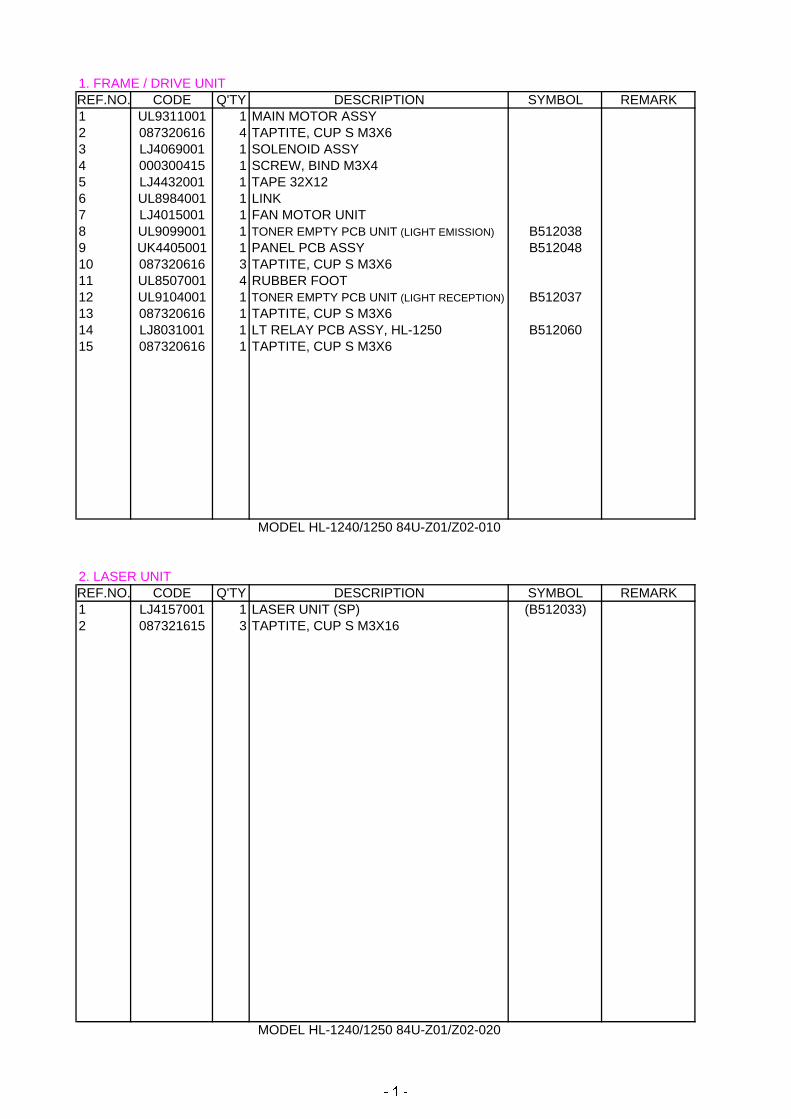
1. FRAME / DRIVE UNIT REF.NO. CODE Q'TY DESCRIPTION SYMBOL REMARK1 UL9311001 1 MAIN MOTOR ASSY 2 087320616 4 TAPTITE, CUP S M3X6 3 LJ4069001 1 SOLENOID ASSY4 000300415 1 SCREW, BIND M3X4 5 LJ4432001 1 TAPE 32X126 UL8984001 1 LINK7 LJ4015001 1 FAN MOTOR UNIT8 UL9099001 1 TONER EMPTY PCB UNIT (LIGHT EMISSION) B5120389 UK4405001 1 PANEL PCB ASSY B51204810 087320616 3 TAPTITE, CUP S M3X6 11 UL8507001 4 RUBBER FOOT12 UL9104001 1 TONER EMPTY PCB UNIT (LIGHT RECEPTION) B51203713 087320616 1 TAPTITE, CUP S M3X6 14 LJ8031001 1 LT RELAY PCB ASSY, HL-1250 B51206015 087320616 1 TAPTITE, CUP S M3X6
MODEL HL-1240/1250 84U-Z01/Z02-010
2. LASER UNIT REF.NO. CODE Q'TY DESCRIPTION SYMBOL REMARK1 LJ4157001 1 LASER UNIT (SP) (B512033)2 087321615 3 TAPTITE, CUP S M3X16
MODEL HL-1240/1250 84U-Z01/Z02-020
� � �
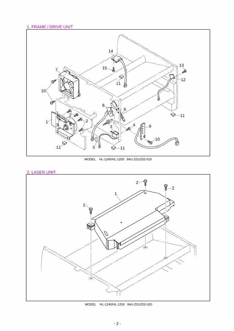
MODEL HL-1240/HL-1250 84U-Z01/Z02-010
1. FRAME / DRIVE UNIT
2. LASER UNIT
- 2 -
MODEL HL-1240/HL-1250 84U-Z01/Z02-020
22
2
1
3 41
14
6
9
115
11
11
11
12
13
2
10
7
8
15
10
2
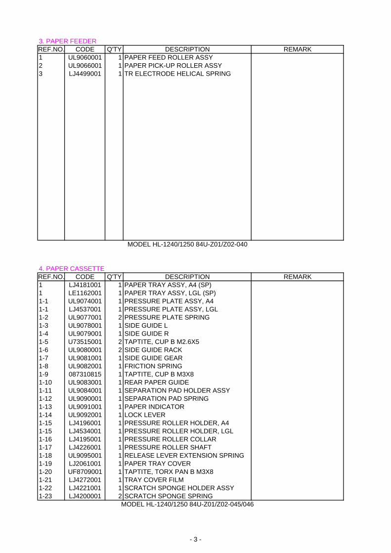
3. PAPER FEEDERREF.NO. CODE Q'TY DESCRIPTION REMARK1 UL9060001 1 PAPER FEED ROLLER ASSY2 UL9066001 1 PAPER PICK-UP ROLLER ASSY3 LJ4499001 1 TR ELECTRODE HELICAL SPRING
MODEL HL-1240/1250 84U-Z01/Z02-040 4. PAPER CASSETTEREF.NO. CODE Q'TY DESCRIPTION REMARK1 LJ4181001 1 PAPER TRAY ASSY, A4 (SP)1 LE1162001 1 PAPER TRAY ASSY, LGL (SP)1-1 UL9074001 1 PRESSURE PLATE ASSY, A4 1-1 LJ4537001 1 PRESSURE PLATE ASSY, LGL1-2 UL9077001 2 PRESSURE PLATE SPRING1-3 UL9078001 1 SIDE GUIDE L1-4 UL9079001 1 SIDE GUIDE R1-5 U73515001 2 TAPTITE, CUP B M2.6X51-6 UL9080001 2 SIDE GUIDE RACK1-7 UL9081001 1 SIDE GUIDE GEAR1-8 UL9082001 1 FRICTION SPRING1-9 087310815 1 TAPTITE, CUP B M3X8 1-10 UL9083001 1 REAR PAPER GUIDE1-11 UL9084001 1 SEPARATION PAD HOLDER ASSY1-12 UL9090001 1 SEPARATION PAD SPRING1-13 UL9091001 1 PAPER INDICATOR1-14 UL9092001 1 LOCK LEVER1-15 LJ4196001 1 PRESSURE ROLLER HOLDER, A41-15 LJ4534001 1 PRESSURE ROLLER HOLDER, LGL1-16 LJ4195001 1 PRESSURE ROLLER COLLAR1-17 LJ4226001 1 PRESSURE ROLLER SHAFT1-18 UL9095001 1 RELEASE LEVER EXTENSION SPRING1-19 LJ2061001 1 PAPER TRAY COVER 1-20 UF8709001 1 TAPTITE, TORX PAN B M3X8 1-21 LJ4272001 1 TRAY COVER FILM1-22 LJ4221001 1 SCRATCH SPONGE HOLDER ASSY1-23 LJ4200001 2 SCRATCH SPONGE SPRING
MODEL HL-1240/1250 84U-Z01/Z02-045/046
- 3 -
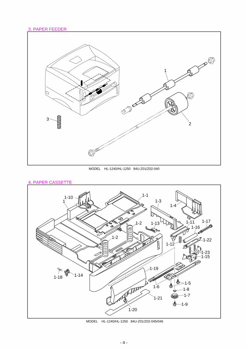
MODEL HL-1240/HL-1250 84U-Z01/Z02-040
3. PAPER FEEDER
4. PAPER CASSETTE
- 4 -
MODEL HL-1240/HL-1250 84U-Z01/Z02-045/046
1
23
1-14
1-2
1-2
1-13
1-81-5
1-19
1-7
1-9
11-4
1-11 1-171-16
1-22
1-151-23
1-6
1-21
1-20
1-12
1-3
1-18
1-10 1-1
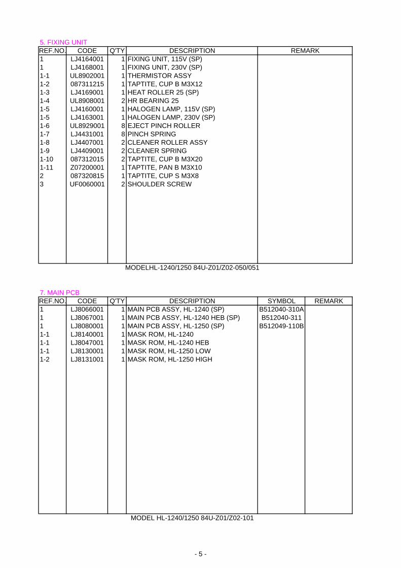
5. FIXING UNIT REF.NO. CODE Q'TY DESCRIPTION REMARK1 LJ4164001 1 FIXING UNIT, 115V (SP)1 LJ4168001 1 FIXING UNIT, 230V (SP)1-1 UL8902001 1 THERMISTOR ASSY 1-2 087311215 1 TAPTITE, CUP B M3X12 1-3 LJ4169001 1 HEAT ROLLER 25 (SP)1-4 UL8908001 2 HR BEARING 251-5 LJ4160001 1 HALOGEN LAMP, 115V (SP)1-5 LJ4163001 1 HALOGEN LAMP, 230V (SP)1-6 UL8929001 8 EJECT PINCH ROLLER 1-7 LJ4431001 8 PINCH SPRING 1-8 LJ4407001 2 CLEANER ROLLER ASSY1-9 LJ4409001 2 CLEANER SPRING1-10 087312015 2 TAPTITE, CUP B M3X20 1-11 Z07200001 1 TAPTITE, PAN B M3X10 2 087320815 1 TAPTITE, CUP S M3X8 3 UF0060001 2 SHOULDER SCREW
MODELHL-1240/1250 84U-Z01/Z02-050/051
7. MAIN PCBREF.NO. CODE Q'TY DESCRIPTION SYMBOL REMARK1 LJ8066001 1 MAIN PCB ASSY, HL-1240 (SP) B512040-310A 1 LJ8067001 1 MAIN PCB ASSY, HL-1240 HEB (SP) B512040-311 1 LJ8080001 1 MAIN PCB ASSY, HL-1250 (SP) B512049-110B 1-1 LJ8140001 1 MASK ROM, HL-12401-1 LJ8047001 1 MASK ROM, HL-1240 HEB1-1 LJ8130001 1 MASK ROM, HL-1250 LOW1-2 LJ8131001 1 MASK ROM, HL-1250 HIGH
MODEL HL-1240/1250 84U-Z01/Z02-101
- 5 -
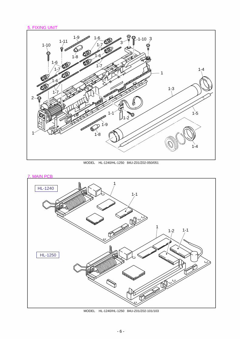
MODEL HL-1240/HL-1250 84U-Z01/Z02-050/051
5. FIXING UNIT
7. MAIN PCB
- 6 -
MODEL HL-1240/HL-1250 84U-Z01/Z02-101/103
1
1-1
11-11-2
HL-1240
HL-1250
1-101-11
1-6
1-7
1-72
1-6
1-6
1-7
1-7
1-6
331-10
1
1-1
1-9
1-8
1-3
1-2
1-4
1-4
1-5
1-9
1-8
1
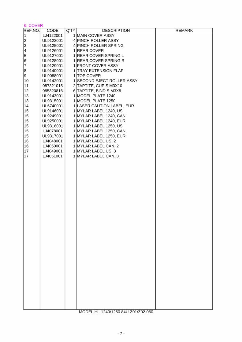
6. COVER REF.NO. CODE Q'TY DESCRIPTION REMARK1 LJ4122001 1 MAIN COVER ASSY2 UL9122001 4 PINCH ROLLER ASSY3 UL9125001 4 PINCH ROLLER SPRING4 UL9126001 1 REAR COVER5 UL9127001 1 REAR COVER SPRING L6 UL9128001 1 REAR COVER SPRING R7 UL9129001 1 FRONT COVER ASSY8 UL9140001 1 TRAY EXTENSION FLAP9 UL9088001 1 TOP COVER10 UL9142001 1 SECOND EJECT ROLLER ASSY11 087321015 2 TAPTITE, CUP S M3X10 12 085320816 6 TAPTITE, BIND S M3X8 13 UL9143001 1 MODEL PLATE 124013 UL9315001 1 MODEL PLATE 125014 UL6740001 1 LASER CAUTION LABEL, EUR15 UL9146001 1 MYLAR LABEL 1240, US15 UL9249001 1 MYLAR LABEL 1240, CAN15 UL9250001 1 MYLAR LABEL 1240, EUR15 UL9316001 1 MYLAR LABEL 1250, US15 LJ4078001 1 MYLAR LABEL 1250, CAN15 UL9317001 1 MYLAR LABEL 1250, EUR16 LJ4048001 1 MYLAR LABEL US, 216 LJ4050001 1 MYLAR LABEL CAN, 217 LJ4049001 1 MYLAR LABEL US, 317 LJ4051001 1 MYLAR LABEL CAN, 3
MODEL HL-1240/1250 84U-Z01/Z02-060
- 7 -
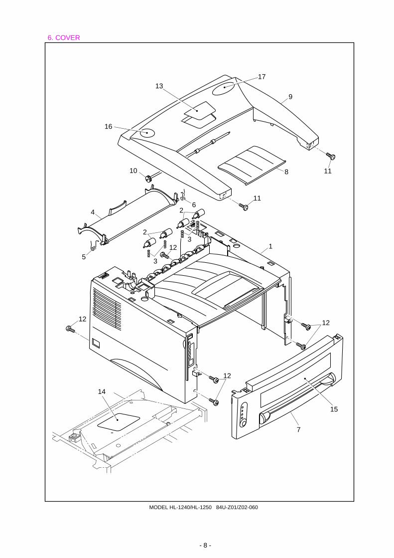
6. COVER
MODEL HL-1240/HL-1250 84U-Z01/Z02-060
- 8 -
7
15
1
12
12
12
9
11
11
8
6
2
5
10
16
1317
4
3
3
2
12
14
8. ENGINE PCB REF.NO. CODE Q'TY DESCRIPTION SYMBOL REMARK1 LJ4178001 1 ENGINE PCB ASSY, 1240 (SP) B512059-3011 LJ4222001 1 ENGINE PCB ASSY, 1250 (SP) B512059-302
MODEL HL-1240/1250 84U-Z01/Z02-151
9. LOW-VOLTAGE POWER SUPPLYREF.NO. CODE Q'TY DESCRIPTION SYMBOL REMARK1 LJ4172001 1 LOW-VOLTAGE PS ASSY, 115V (SP)1 LJ4175001 1 LOW-VOLTAGE PS ASSY, 230V (SP)2 UK4426001 1 INLET UNIT, 115V2 UK4430001 1 INLET UNIT, 230V4 085320816 1 TAPTITE, BIND S M3X85 087320616 1 TAPTITE, CUP S M3X6
MODEL HL-1240/1250 84U-Z01/Z02-200/201
- 9 -
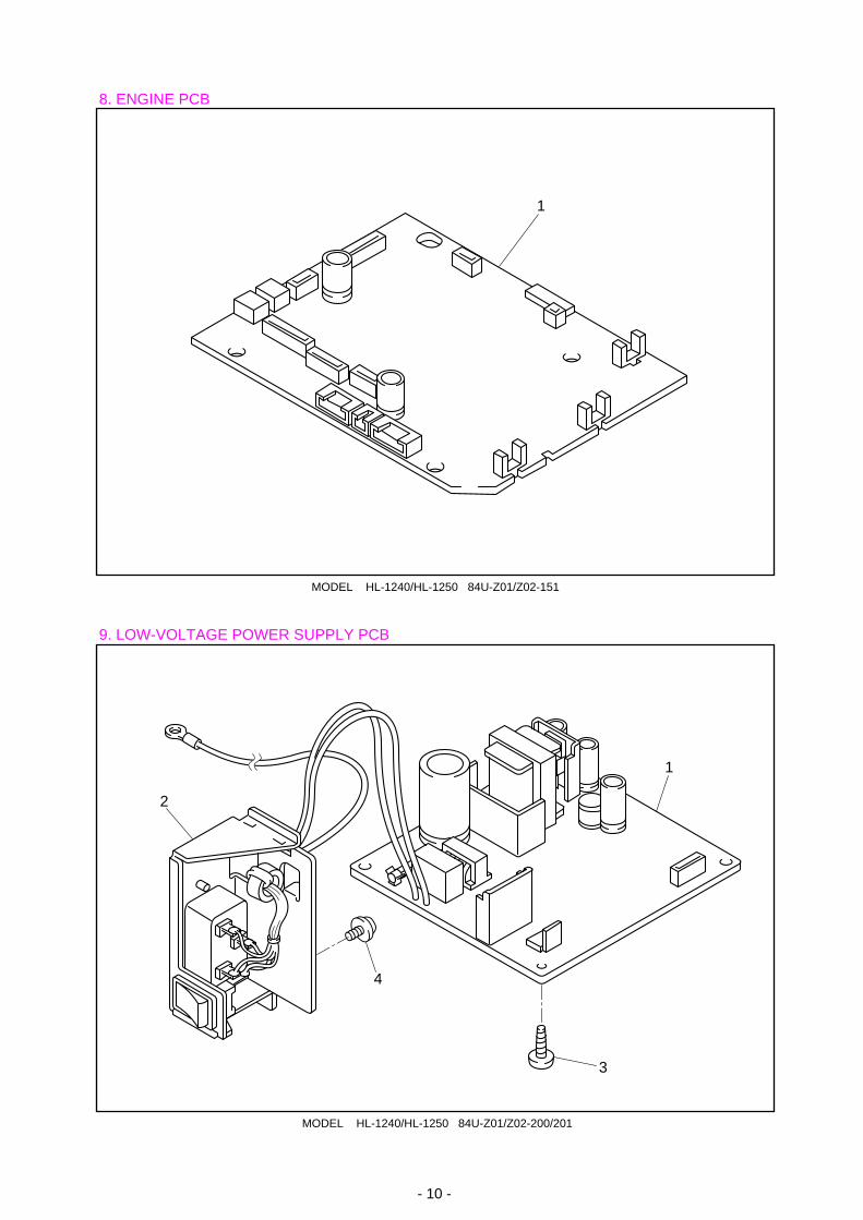
MODEL HL-1240/HL-1250 84U-Z01/Z02-151
8. ENGINE PCB
9. LOW-VOLTAGE POWER SUPPLY PCB
- 10 -
MODEL HL-1240/HL-1250 84U-Z01/Z02-200/201
1
1
2
3
4
10. HIGH-VOLTAGE POWER SUPPLY PR99153REF.NO. CODE Q'TY DESCRIPTION REMARK1 LJ4176001 1 HIGH-VOLTAGE PS ASSY (SP)2 085411215 4 SCREW BIND B TITE M4X12 CHNG
MODEL HL-1240/1250 84U-Z01/Z02-220T/I NO. PR99153
11. AC CORDSREF.NO. CODE Q'TY DESCRIPTION REMARK1A UH1051001 1 AC CORD, UL/CSA1B UK4503001 1 AC CORD ASSY, SAA1C UK4502001 1 AC CORD ASSY, SEV1D UK4099001 1 AC CORD, CHLI1E UH1054001 1 AC CORD, BS1F U34322001 1 AC CORD #6, ISRAEL1G U34320001 1 AC CORD #4, BS1H UK4094001 1 AC CORD, DEMKO1I UK4501001 1 AC CORD ASSY, VDE
MODEL HL-1240 84U-Z01/Z02-230
- 11 -
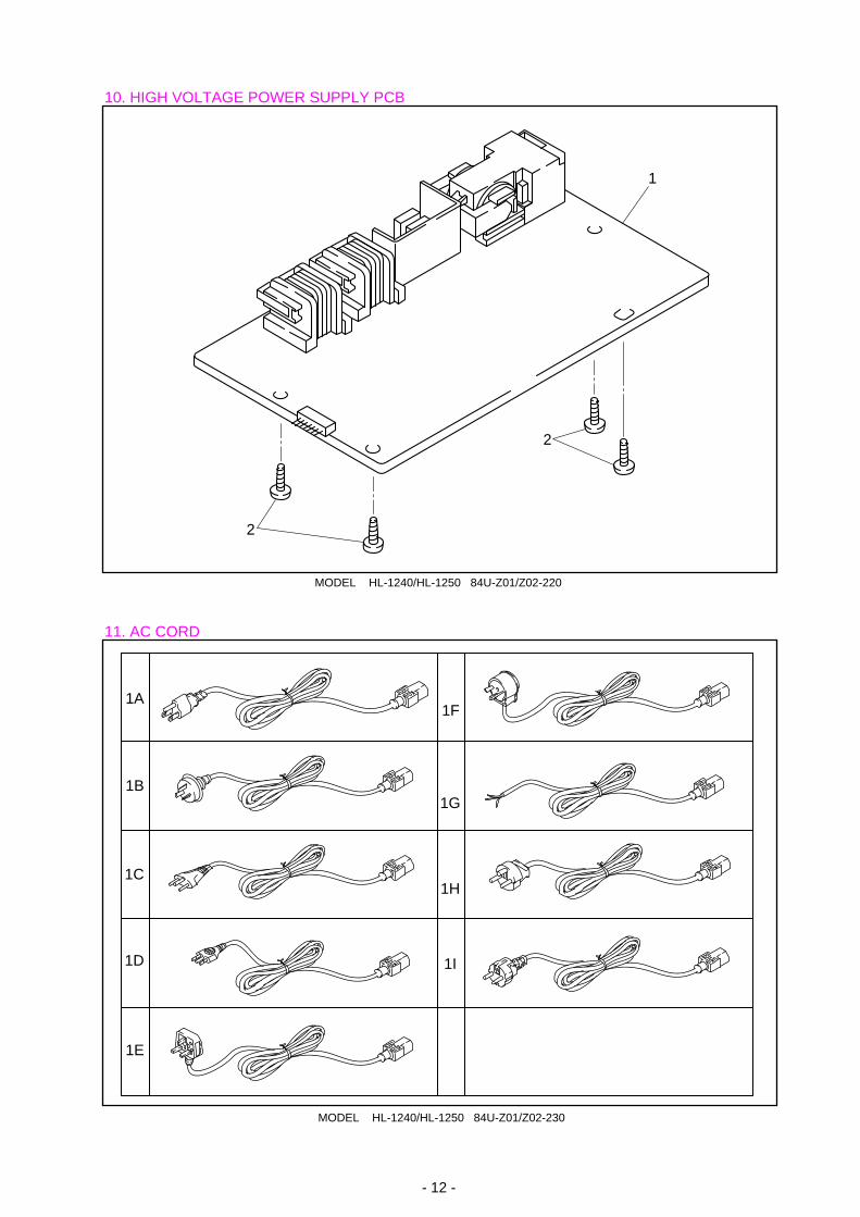
MODEL HL-1240/HL-1250 84U-Z01/Z02-220
10. HIGH VOLTAGE POWER SUPPLY PCB
11. AC CORD
- 12 -
MODEL HL-1240/HL-1250 84U-Z01/Z02-230
1A
1B
1C
1D
1E
1F
1G
1H
1I
2
1
2
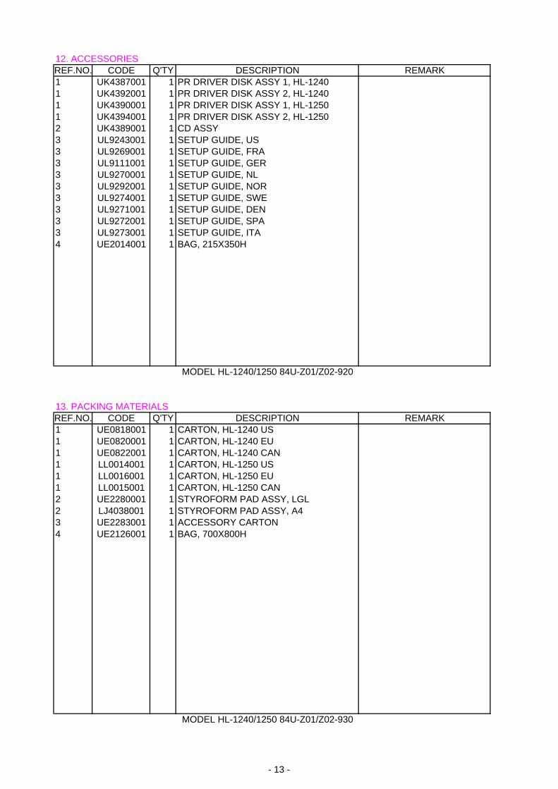
12. ACCESSORIES REF.NO. CODE Q'TY DESCRIPTION REMARK1 UK4387001 1 PR DRIVER DISK ASSY 1, HL-12401 UK4392001 1 PR DRIVER DISK ASSY 2, HL-12401 UK4390001 1 PR DRIVER DISK ASSY 1, HL-1250 1 UK4394001 1 PR DRIVER DISK ASSY 2, HL-12502 UK4389001 1 CD ASSY 3 UL9243001 1 SETUP GUIDE, US 3 UL9269001 1 SETUP GUIDE, FRA 3 UL9111001 1 SETUP GUIDE, GER3 UL9270001 1 SETUP GUIDE, NL3 UL9292001 1 SETUP GUIDE, NOR3 UL9274001 1 SETUP GUIDE, SWE 3 UL9271001 1 SETUP GUIDE, DEN3 UL9272001 1 SETUP GUIDE, SPA3 UL9273001 1 SETUP GUIDE, ITA4 UE2014001 1 BAG, 215X350H
MODEL HL-1240/1250 84U-Z01/Z02-920
13. PACKING MATERIALS REF.NO. CODE Q'TY DESCRIPTION REMARK1 UE0818001 1 CARTON, HL-1240 US1 UE0820001 1 CARTON, HL-1240 EU1 UE0822001 1 CARTON, HL-1240 CAN1 LL0014001 1 CARTON, HL-1250 US1 LL0016001 1 CARTON, HL-1250 EU1 LL0015001 1 CARTON, HL-1250 CAN2 UE2280001 1 STYROFORM PAD ASSY, LGL2 LJ4038001 1 STYROFORM PAD ASSY, A43 UE2283001 1 ACCESSORY CARTON4 UE2126001 1 BAG, 700X800H
MODEL HL-1240/1250 84U-Z01/Z02-930
- 13 -
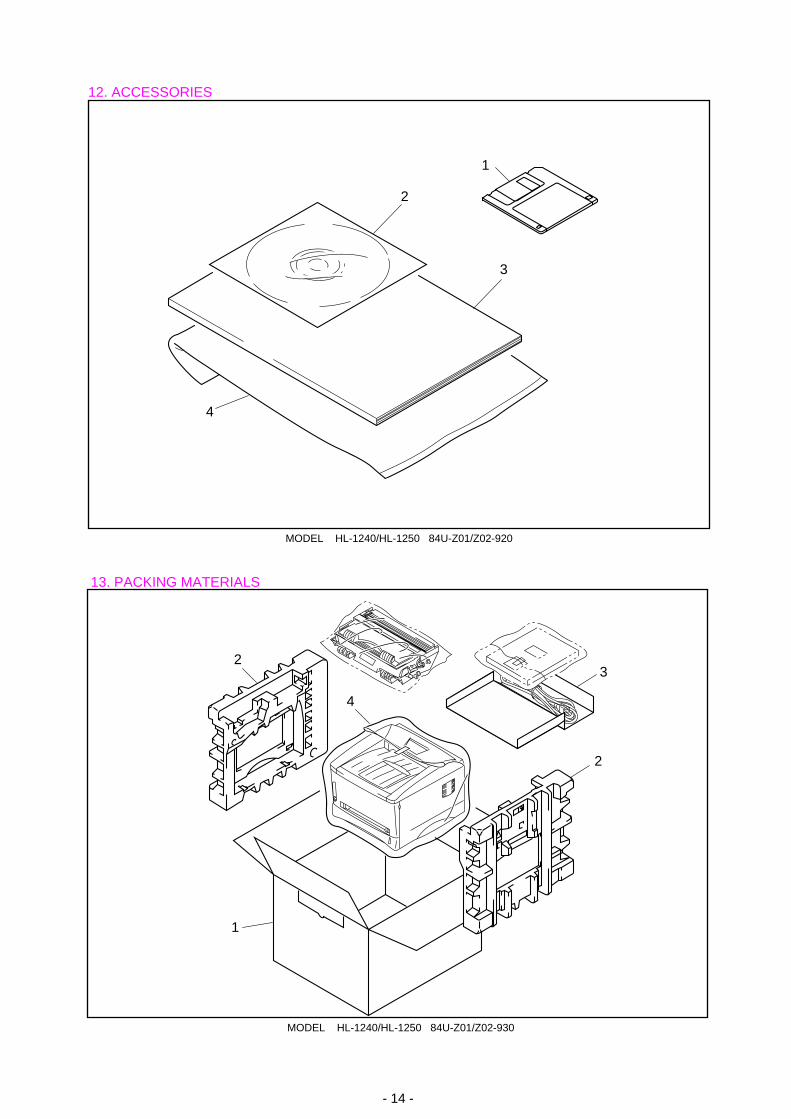
MODEL HL-1240/HL-1250 84U-Z01/Z02-920
12. ACCESSORIES
13. PACKING MATERIALS
- 14 -
MODEL HL-1240/HL-1250 84U-Z01/Z02-930
2
3
4
1
2
2
3
4
1
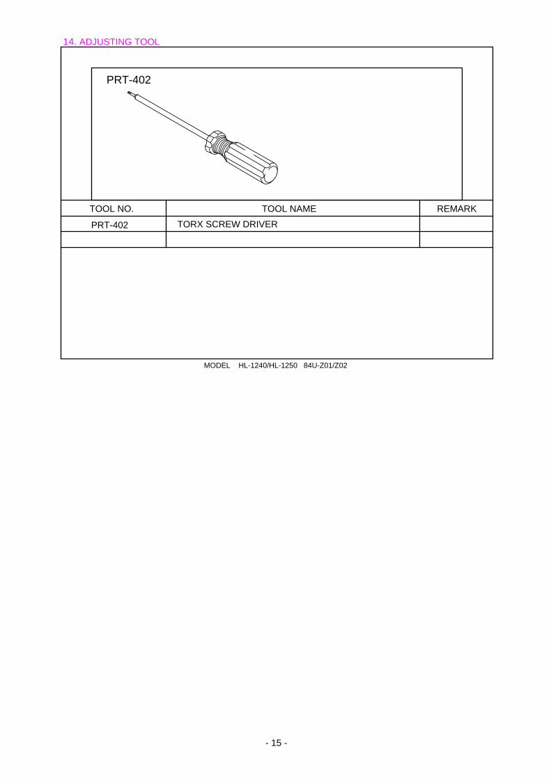
- 15 -
14. ADJUSTING TOOL
PRT-402
TOOL NO. TOOL NAME REMARK
PRT-402 TORX SCREW DRIVER
MODEL HL-1240/HL-1250 84U-Z01/Z02
Brother Laser Printer
HL-1240/1250
User’s Guide
Please read this manual thoroughly before using the printer. You can print or view thismanual from the CD-ROM at any time, please keep the CD-ROM in a convenient place forquick and easy reference at all times.
TABLE OF CONTENTS
TABLE OF CONTENTS
Definitions of Warnings, Cautions, and NotesTo Use the Printer SafelyShipment of the PrinterFor technical and operational assistance
(For USA & CANADA Only)
CHAPTER1 ABOUT THIS PRINTER
What is included in the carton ................................. 1-1Components ...............................................................................1-1
About your printer ................................................... 1-2Features of your printer ........................................... 1-3What printer options are available........................... 1-7Place the printer....................................................... 1-8
Power Supply .............................................................................1-8Environment...............................................................................1-8System Requirements for the Brother Printing Solution forWindows ....................................................................................1-9
What kind of paper can I use ................................. 1-10How to load paper into the Paper Cassette ............ 1-15How to load a sheet of paper manually ................. 1-18How to print on both sides of the paper (ManualDuplexing)............................................................. 1-24What do the LED indications mean....................... 1-27
Ready (Paper) LED indications ...............................................1-28Data (Toner) LED indications .................................................1-29Drum LED indications.............................................................1-31Alarm LED indications............................................................1-31Control Panel Button Operations ............................................1-32Other Control Features ............................................................1-33
CHAPTER 2 OPTIONS
Optional Accessories and Supplies.......................... 2-1The Lower Tray unit (For HL-1250 Only) .............. 2-2How to use the SERIAL INTERFACE (RS-100M)Connection (For HL-1250 Only) ............................ 2-3
How to select the RS-422A (Apple) or RS-232C (IBM) SerialInterface (For HL-1250 Only) ...................................................2-4How to set the Serial Interface Parameters................................2-5How to connect the Serial Interface Cable................................2-8
What is the Brother print server (NC-2010p) ........ 2-10Features ....................................................................................2-10
How to add extra Memory (For HL-1250 Only) ... 2-11How to install additional SIMM memory ...............................2-12
CHAPTER 3 MAINTENANCE
How to replace the Toner Cartridge......................... 3-3How to replace the Drum Unit ................................ 3-9How to clean the printer ........................................ 3-14
Cleaning the printer exterior....................................................3-14Cleaning the printer interior and Drum Unit ...........................3-16
TABLE OF CONTENTS
CHAPTER 4 TROUBLESHOOTING
Identifying your problem......................................... 4-1Control Panel Indications ........................................ 4-2
Operator calls and how to clear them ........................................4-2Service call indications..............................................................4-4
Error messages in the Status Monitor ...................... 4-6Error message printouts ........................................... 4-8Paper Handling ...................................................... 4-10PAPER JAMS and how to clear them.................... 4-11Others ……………………………………………4-16
For printing with the Serial Interface (For HL-1250 Only) ...4-16For DOS users..........................................................................4-16For Apple Macintosh Computers user.....................................4-17For iMac and Power Macintosh G3 with USB........................4-17
Improving the print quality.................................... 4-18How to print correctly ........................................... 4-24
For DOS users..........................................................................4-25
APPENDIX
Printer Technical Specifications ............................. A-1Printing......................................................................................A-1Functions...................................................................................A-3Electrical and Mechanical ........................................................A-4
Parallel Interface Specifications ............................. A-5USB (Universal Serial Bus) Interface..................... A-7Resident Font.......................................................... A-8
HL-1240:...................................................................................A-8Bitmapped Fonts .......................................................................A-8HL-1250 :..................................................................................A-8Bitmapped Fonts .......................................................................A-8Scalable Fonts ...........................................................................A-9
Symbol Sets / Character Sets................................ A-10OCR Symbol Sets (HL-1250 Only)........................................A-10HP LaserJet IIP Mode (HL-1240) ..........................................A-10HP LaserJet 6P Mode (HL-1250)...........................................A-10EPSON Mode (HL-1250 Only) ..............................................A-11IBM Mode (HL-1250 Only) ...................................................A-11
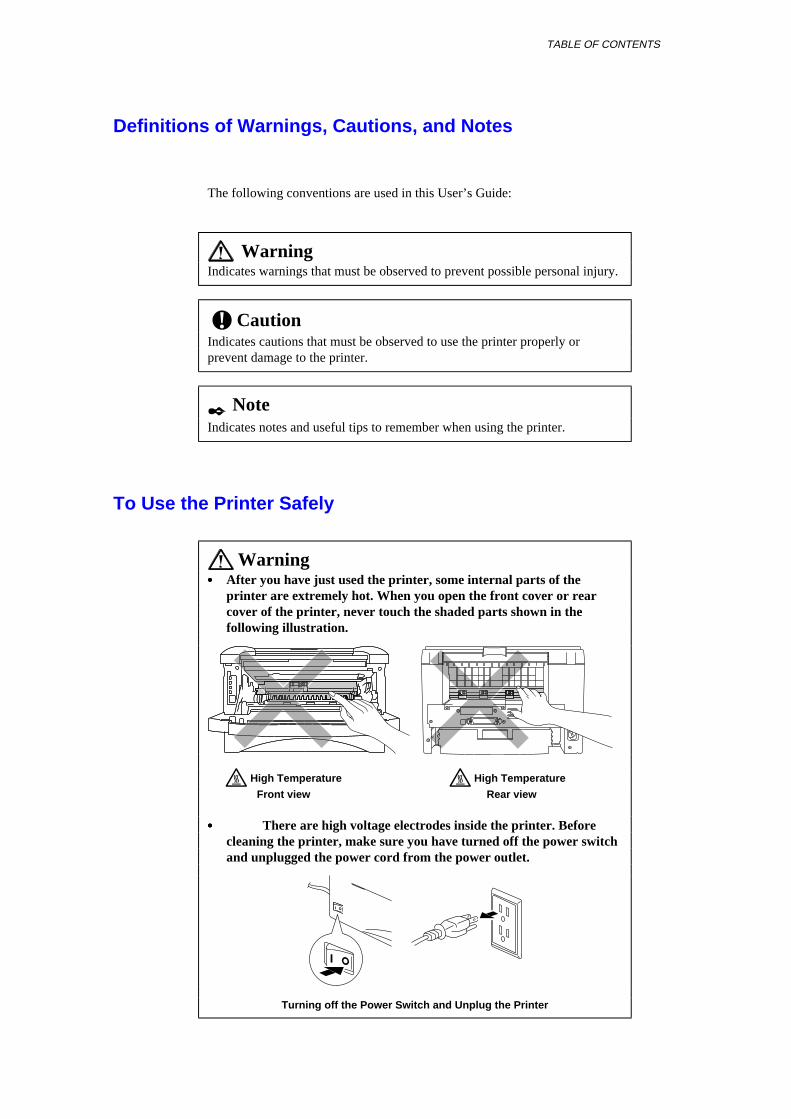
TABLE OF CONTENTS
Definitions of Warnings, Cautions, and Notes
The following conventions are used in this User’s Guide:
WarningIndicates warnings that must be observed to prevent possible personal injury.
! CautionIndicates cautions that must be observed to use the printer properly orprevent damage to the printer.
✒ NoteIndicates notes and useful tips to remember when using the printer.
To Use the Printer Safely
Warning• • • • After you have just used the printer, some internal parts of the
printer are extremely hot. When you open the front cover or rearcover of the printer, never touch the shaded parts shown in thefollowing illustration.
High Temperature High Temperature
Front view Rear view
• • • • There are high voltage electrodes inside the printer. Before
cleaning the printer, make sure you have turned off the power switchand unplugged the power cord from the power outlet.
Turning off the Power Switch and Unplug the Printer
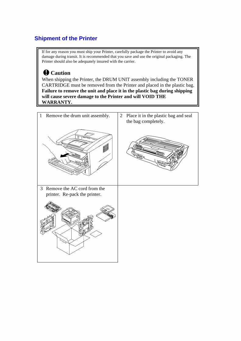
Shipment of the Printer
If for any reason you must ship your Printer, carefully package the Printer to avoid anydamage during transit. It is recommended that you save and use the original packaging. ThePrinter should also be adequately insured with the carrier.
! CautionWhen shipping the Printer, the DRUM UNIT assembly including the TONERCARTRIDGE must be removed from the Printer and placed in the plastic bag.Failure to remove the unit and place it in the plastic bag during shippingwill cause severe damage to the Printer and will VOID THEWARRANTY.
1 Remove the drum unit assembly.
2 Place it in the plastic bag and sealthe bag completely.
3 Remove the AC cord from theprinter. Re-pack the printer.

TABLE OF CONTENTS
(For USA & CANADA Only)
For technical and operational assistance, please call:
In USA 1-800-276-7746 (within US)
In CANADA 1-800-853-6660 514-685-6464 (within Montreal)
If you have comments or suggestions, please write us at:
In USA Printer Customer SupportBrother International Corporation15 MusickIrvine, CA 92618
In CANADA Brother International Corporation (Canada), Ltd.- Marketing Dept.1, rue Hôtel de VilleDollard-des-Ormeaux, PQ, Canada H9B 3H6
BBSFor downloading drivers from our Bulletin Board Service, call:In USA 1-888-298-3616In CANADA 1-514-685-2040Please log on to our BBS with your first name, last name and a four digit number foryour password. Our BBS supports modem speeds up to 14,400, 8 bits no parity, 1 stopbit.
Fax-Back SystemBrother Customer Service has installed an easy to use Fax-Back System so you can getinstant answers to common technical questions and product information for all Brotherproducts. This is available 24 hours a day, 7 days a week. You can use the system tosend the information to any fax machine, not just the one you are calling from.Please call 1-800-521-2846 (U.S.A) or 1-800-681-9838 (Canada) and follow the voiceprompts to receive faxed instructions on how to use the system and your index of Fax-Back subjects.
DEALERS/SERVICE CENTERS (USA only)For the name of an authorized dealer or service center, call 1-800-284-4357.
SERVICE CENTERS (Canada only)For service center addresses in Canada, call 1-800-853-6660
INTERNET ADDRESSFor technical questions and downloading drivers: http://www.brother.com
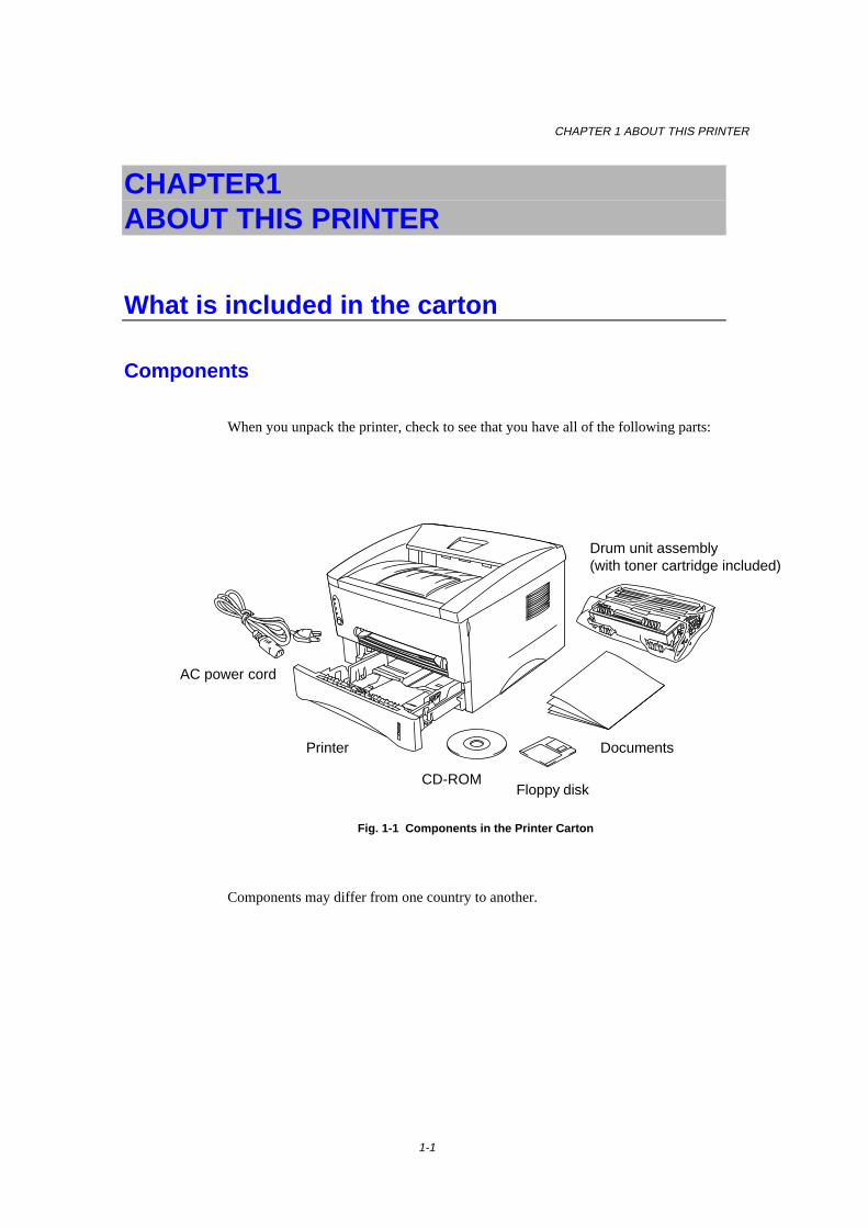
CHAPTER 1 ABOUT THIS PRINTER
1-1
CHAPTER1 ABOUT THIS PRINTER
What is included in the carton
Components
When you unpack the printer, check to see that you have all of the following parts:
Fig. 1-1 Components in the Printer Carton
Components may differ from one country to another.
AC power cord
Drum unit assembly(with toner cartridge included)
Floppy disk
Documents
CD-ROM
Printer

1-2
About your printer
Fig. 1-2 Front View
Fig. 1-3 HL-1240 Rear View Fig. 1-4 HL-1250 Rear View
Tray extension flap
Control panel
Front coverPaper cassette
Manual feed slot
Manual feed paper guides
Face down output tray
Rear cover
AC power inlet
Parallel Interface connector
USB (Universal Serial Interface Bus)connector
AC power inlet
Rear cover
Modular jack for lower tray unit

CHAPTER 1 ABOUT THIS PRINTER
1-3
Features of your printer
❏ High Resolution and Fast Printing Speed
HL-1240 :True 600 x 600 dots per inch (dpi) (GDI mode), True 300 x 300 dots per inch(dpi) (PCL mode) with microfine toner and up to 12 pages per minute (ppm)print speed (A4 or Letter paper).
HL-1250 :True 600 x 600 dots per inch (dpi) and 1200 x 600 dpi for graphics withmicrofine toner and up to 12 pages per minute (ppm) print speed (A4 orLetter paper).
❏ Front Operation
Basic operation of the printer can be done from the front panel.
❏ Versatile Paper Handling
This printer loads paper automatically from the paper cassette. The papercassette can hold A4, letter, B5, Executive, A5 and A6 sizes of paper. Themanual feed slot allows manual paper loading sheet by sheet so you can use avariety of types and sizes of paper. For additional information, see “What kindof paper can I use” in Chapter 1.
❏ Enhanced Printing Performance and User-Friendly Operationfor Windows®
The dedicated printer drivers for Microsoft® Windows® 95/98, Windows 3.1 andWindows NT 4.0 are available on the CD-ROM supplied with your printer. Youcan easily install them into your Windows system using our installer program.The driver supports our unique compression mode to enhance the printing speedin Windows applications and allows you to choose various printer settingsincluding toner save mode, custom paper size, sleep mode, gray scaleadjustment, resolution and many layout functions. You can easily set these printoptions through the Printer Setup Menu.
1-4
❏ Quick Print Setup
You can easily make changes to settings which you need to change frequently ina small selection window on your screen.
❏ Remote Printer Console Program for DOS
The Remote Printer Console (RPC) utility program is available on the CD-ROMsupplied with your printer. When you operate your computer in a DOS (DiskOperating System) environment, this program allows you to easily change thedefault settings of the printer such as fonts, page setup, and emulations.
This program also provides a status monitor program, which is a Terminate-and-Stay Resident (TSR) program. It can monitor the printer status while running inthe background and report the current status or errors on your computer screen.
❏ Popular Printer Emulation Support
These printers support the following popular printer emulation modes.
The HL-1240 supports HP LaserJet IIP (PCL4).
The HL-1250 supports HP LaserJet 6P (PCL6), Epson FX-850 and IBMProprinter XL. When you use DOS application software or Windows version3.0 or earlier, you can use any of these emulations to operate the printer. Theprinter also supports auto-emulation switching between HP and Epson or HP andIBM. If you want to select the printer emulation, you can do it using the RemotePrinter Console Program.
❏ Printer Status Monitor with Bi-directional Parallel Interface
The printer driver can monitor the status of your printer using bi-directionalparallel communications. IEEE-1284 bi-directional parallel printer cable isrecommended.
The printer status monitor program can show the current status of your printer.When printing, the animated dialog box appears on your computer screen toshow the current printing process. If an error occurs, a dialog box will appear tolet you know what to correct. For example: when your printer is out of paper,the dialog box will display “No Paper” and instructions for the propercorrective action.

CHAPTER 1 ABOUT THIS PRINTER
1-5
❏ USB Interface (For Windows 98, iMac and Power MacintoshG3 with USB users Only)
This printer can be connected using the USB (Universal Serial Bus) Interface toa PC which has a USB interface. Drivers to allow you to use the USB port areprovided on the CD-ROM supplied with the printer.
❏ High Resolution Control & Advanced Photoscale Technology(For HL-1250 Only)
High resolution control (HRC) technology provides clear and crisp printouts.Use this function to get smooth text print quality.
Advanced Photoscale Technology (APT) enables the printer to print graphics in256 grayscales, producing nearly photographic quality. Use this function whenyou want to print photographic images.
❏ Enhanced Memory Management
The printer provides its own data compression technology in the printerhardware and the supplied printer driver software, which can automaticallycompress graphic and font data efficiently into the printer’s memory. You canavoid memory errors and print most full page 600 dpi graphic and text data,including larger fonts, with the printer’s standard memory.
1-6
❏ Environment-Friendly
Economy Printing ModeThis feature will cut your printing cost by saving toner. It is useful to obtaindraft copies for proof-reading. You can select from two economy modes—25%toner saving and 50% toner saving—through the Windows printer driversupplied with your printer.
Sleep Mode (Power Save Mode)When the printer is not used for a certain period of time, sleep modeautomatically reduces power consumption. The HL-1240 consumes less than 5Watts, the HL-1250 consumes less than 6 Watts when in sleep mode.
Low Running CostSince the toner cartridge is separate from the drum unit, you need to replace onlythe toner cartridge after approximately 3,000 pages, which is both cost effectiveand ecologically friendly. (An optional high capacity toner unit that will printup to 6,000 pages can also be used in this printer.)
The actual number of pages printed with a toner cartridge may vary dependingon your average type of print job, the figures quoted are based on 5% coverageper page.
You can print up to 20,000 pages with the drum unit, however there are manyfactors that determine the actual drum life.
❏ Bar Code Print (HL-1250 Only)
This printer can print the following 11 types of bar codes:
• Code 39 • UPC-E• Interleaved 2 of 5 • Codabar• EAN-8 • US-PostNet• EAN-13 • ISBN• UPC-A • Code 128• EAN-128
CHAPTER 1 ABOUT THIS PRINTER
1-7
What printer options are available
❏ External Print Server (Brother NC-2010p)
An optional Network print server Brother NC-2010p is available, which allowsyour printer to be connected to your Network via the parallel interface. See“What is the Brother print server (NC-2010p)” in Chapter 2
���� Lower Tray Unit (LT-400) (HL-1250 Only)
A lower tray unit expands the paper source capacity. You can load extra paperand switch between the upper and lower paper sources automatically. See “TheLower Tray Unit” in Chapter 2.
❏ Serial Interface (RS-100M) (HL-1250 Only)
To connect the printer to a computer or a Unix workstation with a serial interfaceor to an Apple Macintosh computer, you need to install the optional interfaceboard (RS-100M). See “How to use the SERIAL INTERFACE (RS-100M)connection” in Chapter 2.
❏ SIMM (Memory) (HL-1250 Only)
The printer has 4.0 Mbytes of standard memory and one slot for optionaladditional memory. The memory can be expanded up to 36 Mbytes by installinga commercially available single in-line memory modules (SIMM). It isrecommended to add memory if you want to print graphics at higher resolutions.
1-8
Place the printer
Please take note of the following before using the printer.
Power Supply
• Use the printer within the specified power range.AC power: ±10% of the rated power voltage in your countryFrequency: 50 Hz (220 V– 240 V) or 50/60 Hz (110–120 V)
Check the rating plate on the back of the printer for your model’sspecification.
• The power cord, including extensions, should not exceed 5 meters (16.5 feet).• Do not share the same power circuit with other high-power appliances,
particularly an air conditioner, copier, shredder and so on. If it is unavoidablethat you must use the printer with these appliances, it is recommended that youuse an isolation transformer or a high-frequency noise filter.
• Use a voltage regulator if the power source is not stable.
Environment
• The printer should be installed near a power outlet, which is easily accessible.• Use the printer only within the following ranges of temperature and humidity.
Ambient temperature: 10°C to 32.5°C (50°F to 90.5°F) Ambient humidity: 20% to 80% (without condensation)
• The printer should be used in a well ventilation room.• Place the printer on a flat, horizontal surface.• Keep the printer clean. Do not place the printer in a dusty place.• Do not place the printer where the ventilation hole of the printer is obstructed.
Keep a gap of approximately 100 mm (4 inches) between the ventilation holeand the wall.
• Do not place the printer where it is exposed to direct sunlight. Use a blind or aheavy curtain to protect the printer from direct sunlight when the printer isunavoidably set up near a window.
• Do not place the printer near devices that contain magnets or generate magneticfields.
• Do not subject the printer to strong physical shocks or vibrations.• Do not expose the printer to open flames or salty or corrosive gasses.• Do not place objects on top of the printer.• Do not place the printer near an air conditioner.• Keep the printer horizontal when carrying.• Do not cover the slots in the top cover.
CHAPTER 1 ABOUT THIS PRINTER
1-9
System Requirements for the Brother Printing Solution forWindows
Check the following system requirements to setup and operate the printer in BrotherPrinting Solution for Windows:
• IBM PC or compatible with 80486 SX or higher microprocessor• 10 MB of space available on your hard disk for the printer driver and all fonts• Microsoft Windows 3.1/3.11, Windows 95/98 or Windows NT 4.0
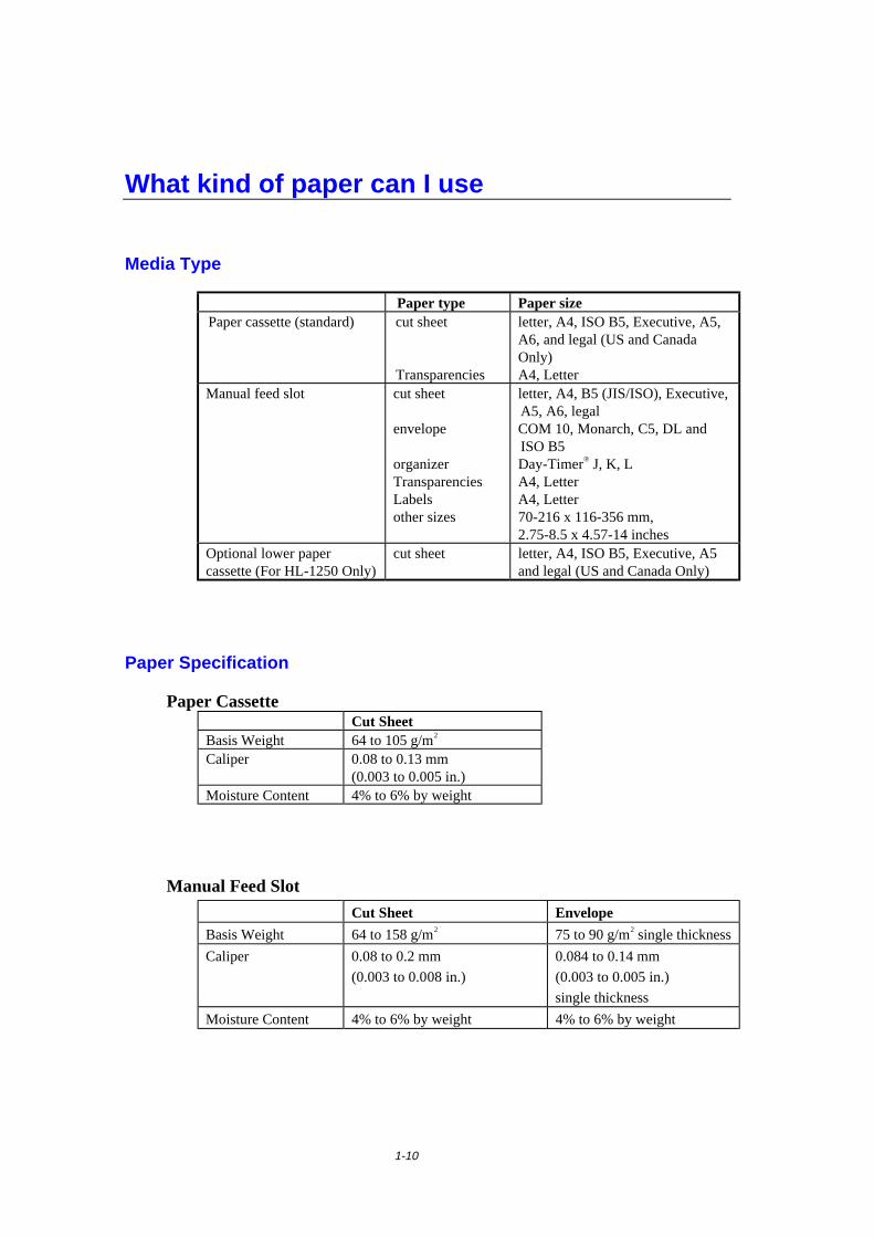
1-10
What kind of paper can I use
Media Type
Paper type Paper sizePaper cassette (standard) cut sheet
Transparencies
letter, A4, ISO B5, Executive, A5,A6, and legal (US and CanadaOnly)A4, Letter
Manual feed slot cut sheet
envelope
organizerTransparenciesLabelsother sizes
letter, A4, B5 (JIS/ISO), Executive,A5, A6, legalCOM 10, Monarch, C5, DL andISO B5Day-Timer® J, K, LA4, LetterA4, Letter70-216 x 116-356 mm,2.75-8.5 x 4.57-14 inches
Optional lower papercassette (For HL-1250 Only)
cut sheet letter, A4, ISO B5, Executive, A5and legal (US and Canada Only)
Paper Specification
Paper CassetteCut Sheet
Basis Weight 64 to 105 g/m2
Caliper 0.08 to 0.13 mm(0.003 to 0.005 in.)
Moisture Content 4% to 6% by weight
Manual Feed Slot
Cut Sheet Envelope
Basis Weight 64 to 158 g/m2 75 to 90 g/m2 single thickness
Caliper 0.08 to 0.2 mm
(0.003 to 0.008 in.)
0.084 to 0.14 mm
(0.003 to 0.005 in.)
single thickness
Moisture Content 4% to 6% by weight 4% to 6% by weight
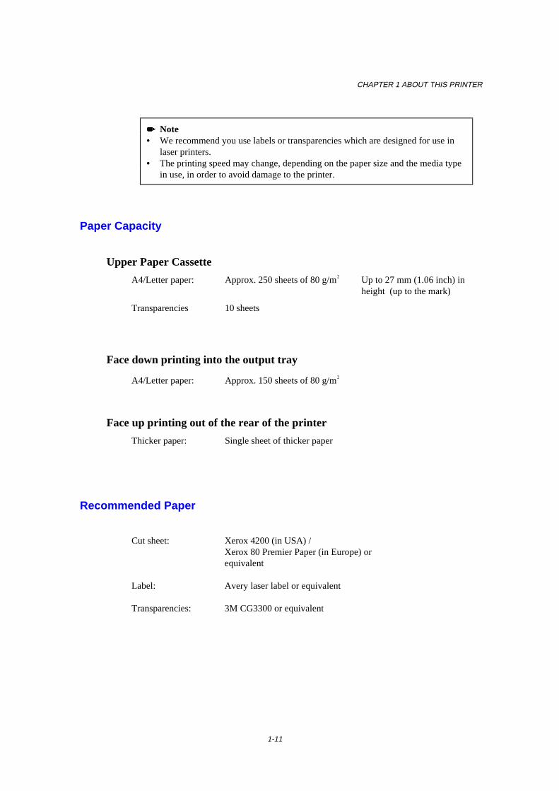
CHAPTER 1 ABOUT THIS PRINTER
1-11
���� Note• We recommend you use labels or transparencies which are designed for use in
laser printers.• The printing speed may change, depending on the paper size and the media type
in use, in order to avoid damage to the printer.
Paper Capacity
Upper Paper Cassette
A4/Letter paper: Approx. 250 sheets of 80 g/m2 Up to 27 mm (1.06 inch) inheight (up to the mark)
Transparencies 10 sheets
Face down printing into the output tray
A4/Letter paper: Approx. 150 sheets of 80 g/m2
Face up printing out of the rear of the printer
Thicker paper: Single sheet of thicker paper
Recommended Paper
Cut sheet: Xerox 4200 (in USA) /Xerox 80 Premier Paper (in Europe) orequivalent
Label: Avery laser label or equivalent
Transparencies: 3M CG3300 or equivalent
1-12
Remarks
It is recommended that you test paper, especially special sizes and types of paperand heavy paper, on this printer before purchasing large quantities.
Avoid using coated paper, such as vinyl coated paper.
Avoid using preprinted or highly textured paper.
Use a recommended type of paper, especially plain paper and transparencies, foroptimum printing. For more information on paper specifications, consult yournearest authorized sales representative or the place you purchased your printer.
If the paper has problems feeding from the paper cassette, use the manual feed slotand try again.
Use neutral paper. Do not use acid paper to avoid any damage to the printer drumunit.
Make sure that you have selected the appropriate media type in the printer driver foroptimum printing.
The print quality might be degraded or the life of the drum unit might be shortenedwith the following usage. Using the printer for special print jobs for long periods oftime (i.e. printing name cards, etc.)
Cut Sheet
We recommend you use long-grained paper for the best print quality.If you are using short-grained paper, it may be the cause of paper jams.
Labels / Transparencies
Avoid feeding labels with the carrier sheet exposed, or your printer will bedamaged.
We recommend you use labels or transparencies which are designed for use in laserprinters.
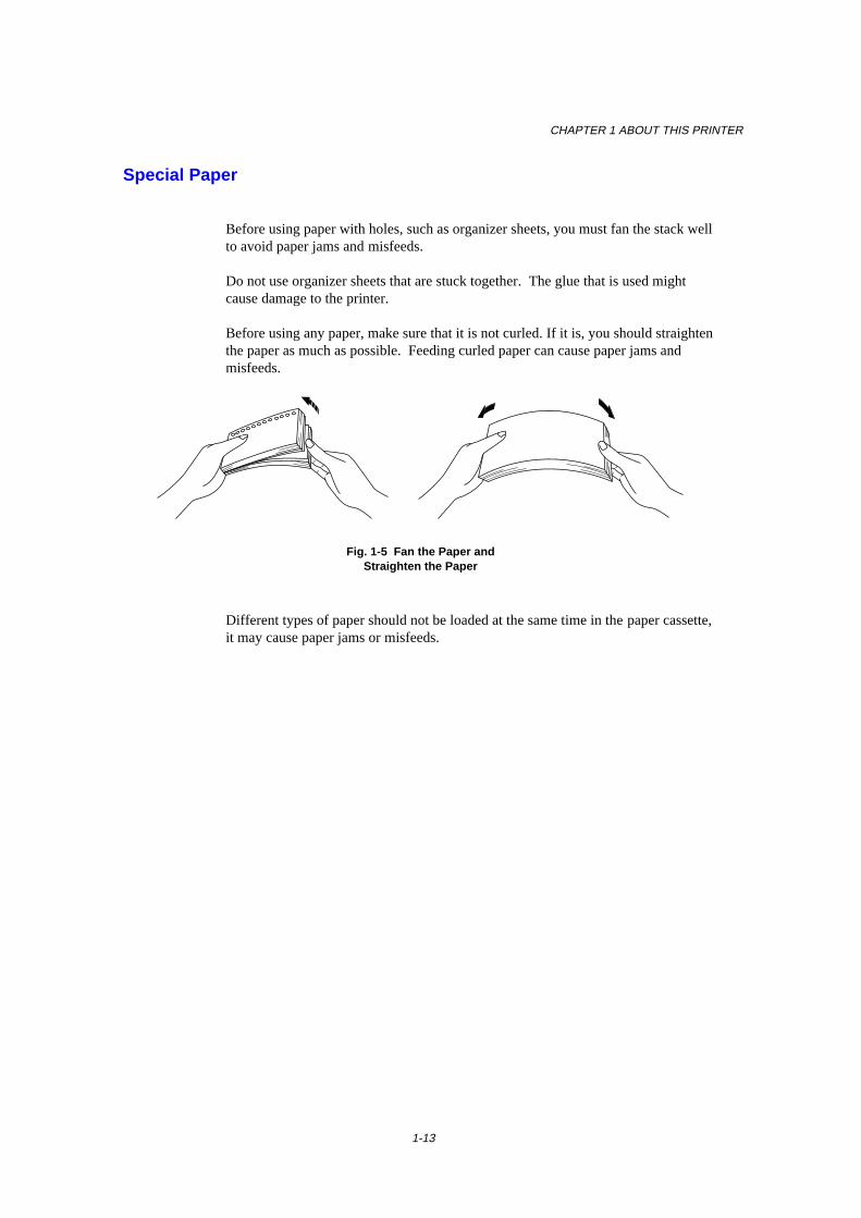
CHAPTER 1 ABOUT THIS PRINTER
1-13
Special Paper
Before using paper with holes, such as organizer sheets, you must fan the stack wellto avoid paper jams and misfeeds.
Do not use organizer sheets that are stuck together. The glue that is used mightcause damage to the printer.
Before using any paper, make sure that it is not curled. If it is, you should straightenthe paper as much as possible. Feeding curled paper can cause paper jams andmisfeeds.
Fig. 1-5 Fan the Paper andStraighten the Paper
Different types of paper should not be loaded at the same time in the paper cassette,it may cause paper jams or misfeeds.
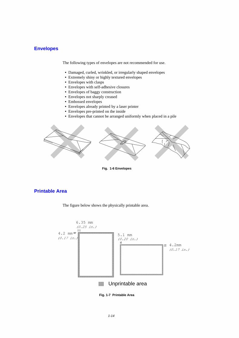
1-14
Envelopes
The following types of envelopes are not recommended for use.
• Damaged, curled, wrinkled, or irregularly shaped envelopes• Extremely shiny or highly textured envelopes• Envelopes with clasps• Envelopes with self-adhesive closures• Envelopes of baggy construction• Envelopes not sharply creased• Embossed envelopes• Envelopes already printed by a laser printer• Envelopes pre-printed on the inside• Envelopes that cannot be arranged uniformly when placed in a pile
Fig. 1-6 Envelopes
Printable Area
The figure below shows the physically printable area.
4.2 mm
4.2mm
��������������������������������������������������������
�����������������
�������
����������
Unprintable area
5.1 mm
���������������������������������������������������������������������������������������������������������������������������������������������������������������������������������������������������������������������������������������������������������������������������������������������������������������������������������������������������������������������������������������������������������������������������������������������������������������������������������������������������������������������������������������������������������������������������������������������������������������������������������������������������������������������������������������������������������������������������������������������������������������������������������������������������������������������������������������������������������������������������������������������������������������������������������������������������������������������������������������������������������������������������������������������������������������������������������������������������������������������������������������������������������������������������������������������������������������������������������������������������������������������������������������������������������������������������������������������������������������������������������������������������������������������������������������������������������������������������������������������������������������������������������������������������������������������������������������������������������������������������������������������������������������������������������������������������������������������������������������������������������������������������������������������������������������������������������������������������������������������������������������������������������������������������������������������������������������������������������������������������������������������������������������������������������������������������������������������������������������������������������������������������������������������������������������������������������������������������������������������������������������������������������������������������������������������������������������������������������������������������������������������������������������������������������������������������������������������������������������������������������������������������������������������������������������������������������������������������������������������������������������������������������������������������������������������������������������������������������������������������������������������������������������������������������������������������������������������������������������������������������������������������������������������������������������������������
������������������������������������������������������������������������������������������������������������������������������������������������������������������������������������������������������������������������������������������������������������������������������������������������������������������������������������������������������������������������������������������������������������������������������������������������������������������������������������������������������������������������������������������������������������������������������������������������������������������������������������������������������������������������������������������������������������������������������������������������������������������������������������������������������������������������������������������������������������������������������������������������������������������������������������������������������������������������������������������������������������������������������������������������������������������������������������������������������������������������������������������������������������������������������������������������������������������������������������������������������������������������������������������������������������������������������������������������������������������������������������������������������������������������������������������������������������������������������������������������������������������������������������������������������������������������������������������������������������������������������������������������������������������������������������������������������������������������������������������������������������������������������������������������������������������������������������������������������������������������������������������������������������������������������������������������������������������������������������������������������������������������������������������������������������������������������������������������������������������������������������������������������������������������������������������������������������������������������������������������������������������������������������������������������������������������������������������������������������������������������������������������������������������������������������������������������������������������������������������������������������������������������������������������������������������������������������������������������������������������������������������������������������������������������������������������������������������������������������������������������������������������������������������������������������������������������������������������������������������������������������������������������������������������������������������������������������������������������������������������������������������������������������������������������������������������������������������������������������������������������������������������������������������������������������������������������������������������������������������������������������������������������������������������������������������������������������������������������������������������������������������������������������������������������������������������������������������������������������������������������������������������������������������������������������������������������������������������������������������������������������������
6.35 mm
(0.17 in.)
(0.25 in.)
(0.20 in.)
(0.17 in.)
Fig. 1-7 Printable Area
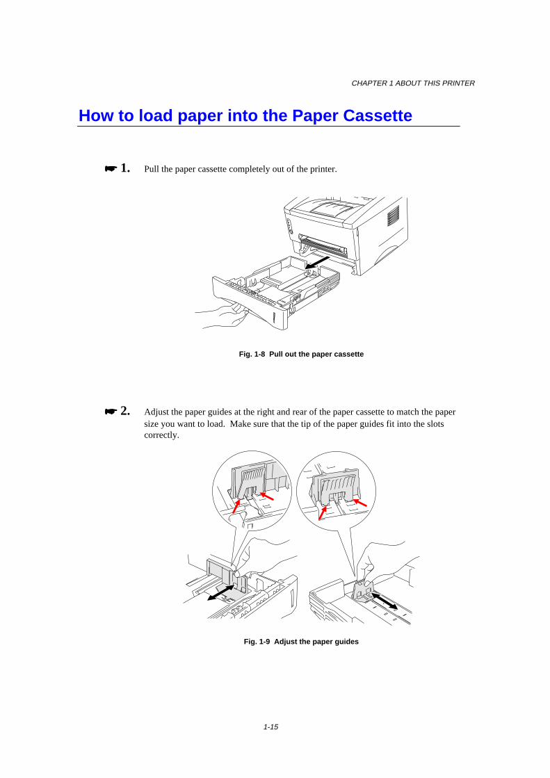
CHAPTER 1 ABOUT THIS PRINTER
1-15
How to load paper into the Paper Cassette
���� 1. Pull the paper cassette completely out of the printer.
Fig. 1-8 Pull out the paper cassette
���� 2. Adjust the paper guides at the right and rear of the paper cassette to match the papersize you want to load. Make sure that the tip of the paper guides fit into the slotscorrectly.
Fig. 1-9 Adjust the paper guides
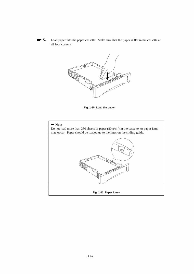
1-16
���� 3. Load paper into the paper cassette. Make sure that the paper is flat in the cassette atall four corners.
Fig. 1-10 Load the paper
���� NoteDo not load more than 250 sheets of paper (80 g/m2) in the cassette, or paper jamsmay occur. Paper should be loaded up to the lines on the sliding guide.
Fig. 1-11 Paper Lines
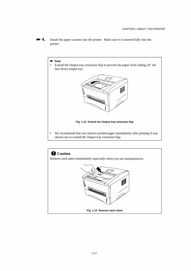
CHAPTER 1 ABOUT THIS PRINTER
1-17
���� 4. Install the paper cassette into the printer. Make sure it is inserted fully into theprinter.
� Note• Extend the Output tray extension flap to prevent the paper from sliding off the
face down output tray.
Fig. 1-12 Extend the Output tray extension flap
• We recommend that you remove printed pages immediately after printing if youchoose not to extend the Output tray extension flap.
! CautionRemove each sheet immediately especially when you use transparencies.
Fig. 1-13 Remove each sheet
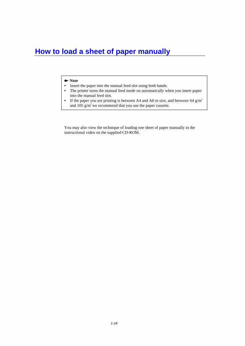
1-18
How to load a sheet of paper manually
���� Note• Insert the paper into the manual feed slot using both hands.• The printer turns the manual feed mode on automatically when you insert paper
into the manual feed slot.• If the paper you are printing is between A4 and A6 in size, and between 64 g/m2
and 105 g/m2 we recommend that you use the paper cassette.
You may also view the technique of loading one sheet of paper manually in theinstructional video on the supplied CD-ROM.
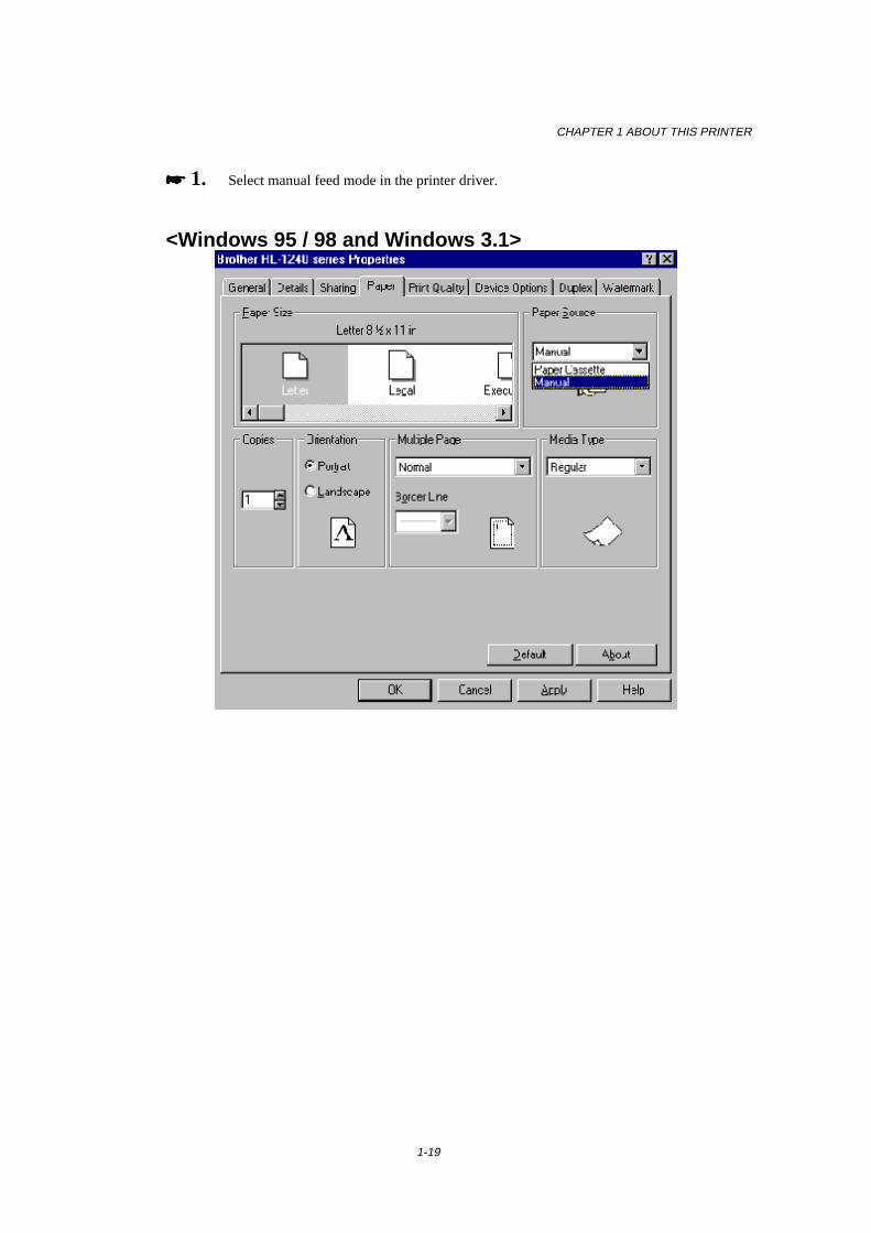
CHAPTER 1 ABOUT THIS PRINTER
1-19
���� 1. Select manual feed mode in the printer driver.
<Windows 95 / 98 and Windows 3.1>
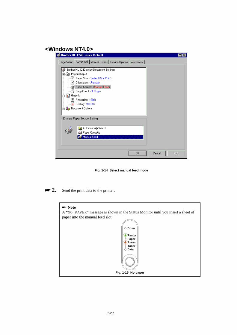
1-20
<Windows NT4.0>
Fig. 1-14 Select manual feed mode
���� 2. Send the print data to the printer.
� NoteA “NO PAPER” message is shown in the Status Monitor until you insert a sheet ofpaper into the manual feed slot.
Ready
AlarmPaper
TonerData
Drum
Fig. 1-15 No paper
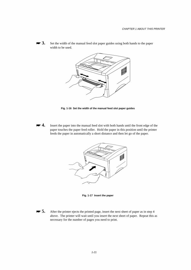
CHAPTER 1 ABOUT THIS PRINTER
1-21
���� 3. Set the width of the manual feed slot paper guides using both hands to the paperwidth to be used.
Fig. 1-16 Set the width of the manual feed slot paper guides
���� 4. Insert the paper into the manual feed slot with both hands until the front edge of thepaper touches the paper feed roller. Hold the paper in this position until the printerfeeds the paper in automatically a short distance and then let go of the paper.
Fig. 1-17 Insert the paper
���� 5. After the printer ejects the printed page, insert the next sheet of paper as in step 4above. The printer will wait until you insert the next sheet of paper. Repeat this asnecessary for the number of pages you need to print.
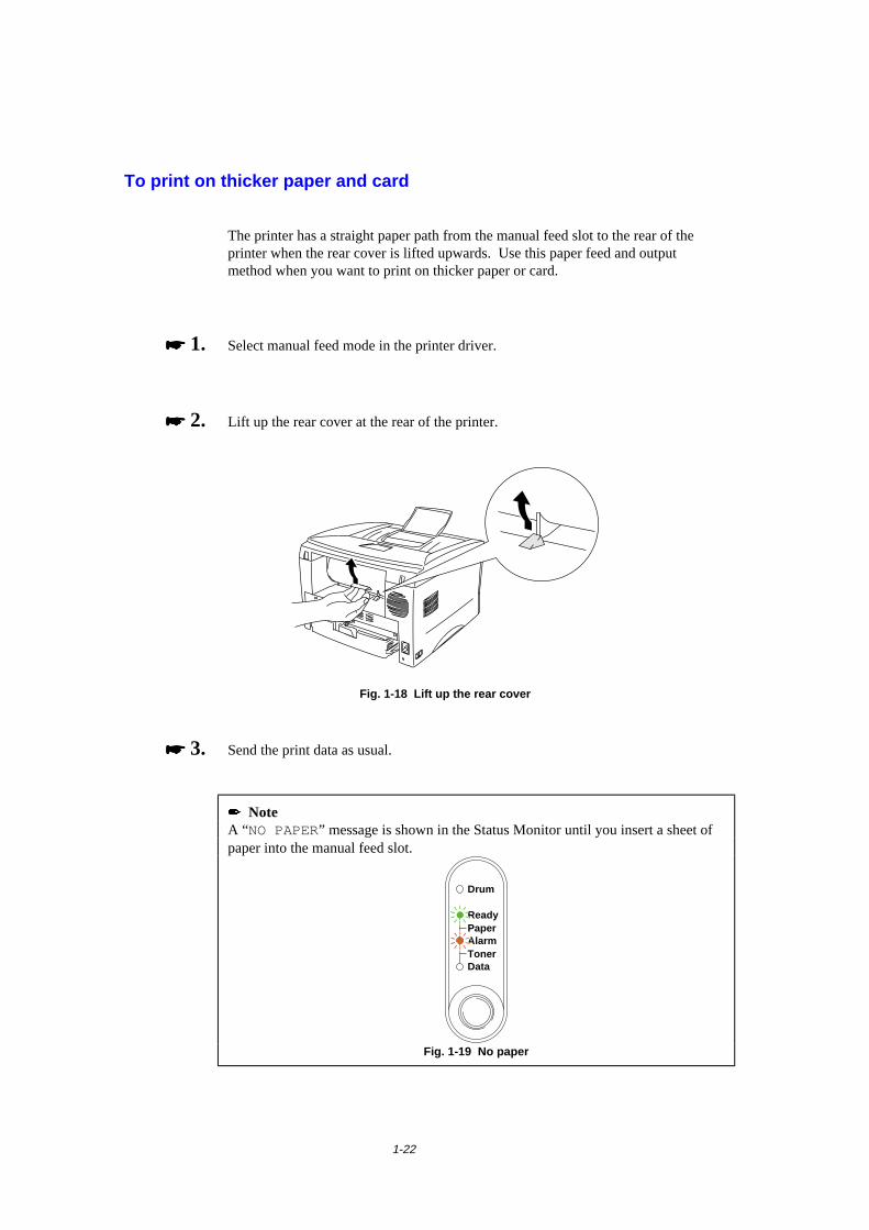
1-22
To print on thicker paper and card
The printer has a straight paper path from the manual feed slot to the rear of theprinter when the rear cover is lifted upwards. Use this paper feed and outputmethod when you want to print on thicker paper or card.
���� 1. Select manual feed mode in the printer driver.
���� 2. Lift up the rear cover at the rear of the printer.
Fig. 1-18 Lift up the rear cover
���� 3. Send the print data as usual.
� NoteA “NO PAPER” message is shown in the Status Monitor until you insert a sheet ofpaper into the manual feed slot.
Ready
AlarmPaper
TonerData
Drum
Fig. 1-19 No paper
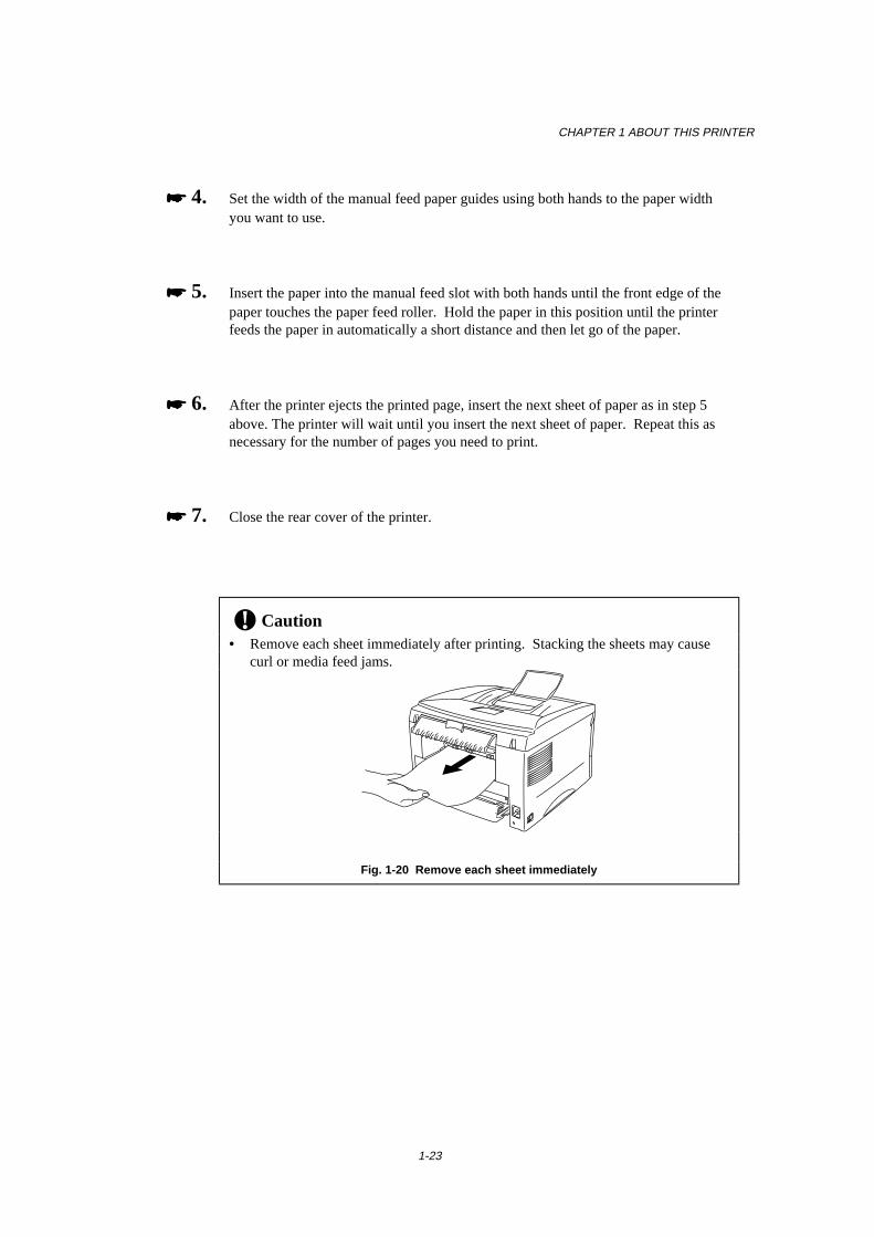
CHAPTER 1 ABOUT THIS PRINTER
1-23
���� 4. Set the width of the manual feed paper guides using both hands to the paper widthyou want to use.
���� 5. Insert the paper into the manual feed slot with both hands until the front edge of thepaper touches the paper feed roller. Hold the paper in this position until the printerfeeds the paper in automatically a short distance and then let go of the paper.
���� 6. After the printer ejects the printed page, insert the next sheet of paper as in step 5above. The printer will wait until you insert the next sheet of paper. Repeat this asnecessary for the number of pages you need to print.
���� 7. Close the rear cover of the printer.
! Caution• Remove each sheet immediately after printing. Stacking the sheets may cause
curl or media feed jams.
Fig. 1-20 Remove each sheet immediately
1-24
How to print on both sides of the paper(Manual Duplexing)
The supplied printer drivers for Windows 95/98, Windows 3.1 and Windows NT 4.0all enable manual duplex printing. For more information about how to make thesettings, see the Help text in the printer driver.
Guidelines for printing on both sides of the paper
1 It may cause wrinkling if the paper is too thin.
2 If paper is curled, straighten it and then set it into the paper cassette.
3 The paper type should be regular paper. Do not use bond paper.
4 When setting paper into the paper cassette, empty the cassette first, then insertthe printed paper only, printed side face up. (Do not add the printed paper ontothe top of the unprinted paper stack.)
5 If the paper is not feeding correctly, it is possible that the paper is curled, removethe paper and straighten it.
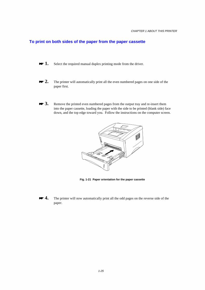
CHAPTER 1 ABOUT THIS PRINTER
1-25
To print on both sides of the paper from the paper cassette
���� 1. Select the required manual duplex printing mode from the driver.
���� 2. The printer will automatically print all the even numbered pages on one side of thepaper first.
���� 3. Remove the printed even numbered pages from the output tray and re-insert theminto the paper cassette, loading the paper with the side to be printed (blank side) facedown, and the top edge toward you. Follow the instructions on the computer screen.
Fig. 1-21 Paper orientation for the paper cassette
���� 4. The printer will now automatically print all the odd pages on the reverse side of thepaper.

1-26
To print on both sides of the paper from the manual feed slot
! Caution• Before re-inserting the sheets, you have to straighten them, or you may get paper
feed errors.• The use of very thin or very thick paper is not recommended.• When you use the Manual Duplex function, it is possible that paper jams may
occur or print quality might not be satisfactory. If a paper jam has occurred,please refer to “PAPER JAMS and how to clear them” in Chapter 4.
���� 1. Select the required manual duplex printing mode and manual feed mode from thedriver.
���� 2. Using both hands, insert the paper into the manual feed slot with the side to beprinted first facing upwards.Follow the instructions on the computer screen.Repeat this until you have printed all the even numbered pages.
���� 3. Remove the printed even numbered pages from the output tray and re-insert them inorder into the manual feed slot, loading the paper with the side to be printed (blankside) face up, and the top of the printed side towards the printer. Follow theinstructions on the computer screen.
Fig. 1-22 Paper operation for the manual feed slot
���� 4. Repeat action 3 until you have printed all the odd numbered pages on the reverseside of the paper.

CHAPTER 1 ABOUT THIS PRINTER
1-27
What do the LED indications mean
This section refers to the following LED and button on the printer control panel.
The LED indications as shown in the table below are used in the illustrations in thischapter.
❍ LED is Off
LED is Blinking
� LED is On
Drum
Ready
AlarmPaper
TonerData
Fig. 1-23 LEDs and Button on the Control Panel
✒ NoteWhen the power switch is off or the printer is in sleep mode, all LEDs including theReady LED are off.
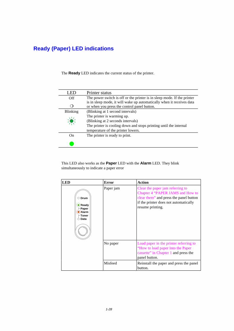
1-28
Ready (Paper) LED indications
The Ready LED indicates the current status of the printer.
LED Printer statusOff
❍
The power switch is off or the printer is in sleep mode. If the printeris in sleep mode, it will wake up automatically when it receives dataor when you press the control panel button.
Blinking (Blinking at 1 second intervals)The printer is warming up.(Blinking at 2 seconds intervals)The printer is cooling down and stops printing until the internaltemperature of the printer lowers.
On
�
The printer is ready to print.
This LED also works as the Paper LED with the Alarm LED. They blinksimultaneously to indicate a paper error
LED Error Action
Ready
AlarmPaper
TonerData
Drum
Paper jam Clear the paper jam referring toChapter 4 “PAPER JAMS and How toclear them” and press the panel buttonif the printer does not automaticallyresume printing.
No paper Load paper in the printer referring to“How to load paper into the Papercassette” in Chapter 1 and press thepanel button.
Misfeed Reinstall the paper and press the panelbutton.

CHAPTER 1 ABOUT THIS PRINTER
1-29
Data (Toner) LED indications
The Data LED indicates the current status of the print data process.
LED Printer statusOff
❍
The printer has no print data.
Blinking The printer is receiving data from the computer or the printer isprocessing data in memory.
On
�
Print data remains in the printer memory. If the Data LED is on for along period of time and nothing has printed, you need to press thebutton to print the remaining data.
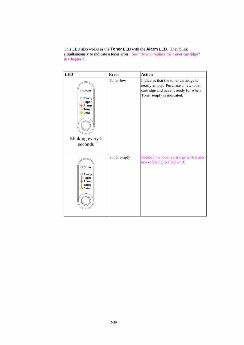
1-30
This LED also works as the Toner LED with the Alarm LED. They blinksimultaneously to indicate a toner error. See “How to replace the Toner cartridge”in Chapter 3 .
LED Error Action
Ready
AlarmPaper
TonerData
Drum
Blinking every 5seconds
Toner low Indicates that the toner cartridge isnearly empty. Purchase a new tonercartridge and have it ready for whenToner empty is indicated.
Ready
AlarmPaper
TonerData
Drum
Toner empty Replace the toner cartridge with a newone referring to Chapter 3.
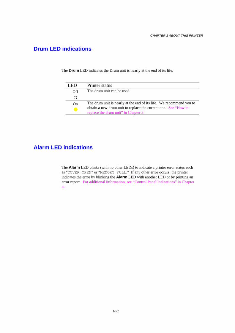
CHAPTER 1 ABOUT THIS PRINTER
1-31
Drum LED indications
The Drum LED indicates the Drum unit is nearly at the end of its life.
LED Printer statusOff
❍
The drum unit can be used.
On
●
The drum unit is nearly at the end of its life. We recommend you toobtain a new drum unit to replace the current one. See “How toreplace the drum unit” in Chapter 3.
Alarm LED indications
The Alarm LED blinks (with no other LEDs) to indicate a printer error status suchas “COVER OPEN” or “MEMORY FULL.” If any other error occurs, the printerindicates the error by blinking the Alarm LED with another LED or by printing anerror report. For additional information, see “Control Panel Indications” in Chapter4.
1-32
Control Panel Button Operations
The control panel button is used for the following purposes depending on thesituation.
Cancel PrintingIf you press the button during printing, the printer immediately stops printing andejects the paper.
Wake-UpIf the printer is in sleep mode, pressing the button wakes it up into the ready state. Itwill take up to 45 seconds for the printer to go into the Ready state.
Form FeedIf the Data LED is on, press the button. The printer prints any data remaining in theprinter memory: this operation is called “Form Feed.”
Error RecoveryIf an error occurs, the printer will recover from some errors automatically. If theerror does not clear automatically, press the button to clear the error and continueprinter operation.
CHAPTER 1 ABOUT THIS PRINTER
1-33
Other Control Features
The printer has the following useful features:
Sleep Mode
When the printer does not receive data for a certain period of time (timeout), itenters sleep mode. Sleep mode acts as though the printer was turned off. Thedefault timeout is 5 minutes and it is automatically adjusted to the most suitabletime-out setting depending on the frequency of your printer use (Intelligent SleepMode). While the printer is in sleep mode, all the LEDs are off and it is as if it wasturned off, but the printer can still receive data from the computer. Receiving a printfile or document automatically wakes up the printer to start printing. Pressing thebutton also wakes up the printer.
✒ Note• When the printer goes into sleep mode, the fan will not stop until the printer
engine has cooled down.
• Sleep mode allows the print engine to cool, so the temperature of your room andhow long the printer has been in sleep mode affects the warm-up time. Thiswarm-up time can take up to 45 seconds. The Ready LED blinks to indicate thatthe printer is warming up.
• You can change the timeout for the sleep mode with the supplied printer driver(all models) or Remote Printer Console program. Refer to the Help section inthe printer driver or RPC program for more information about the sleep modesetting.
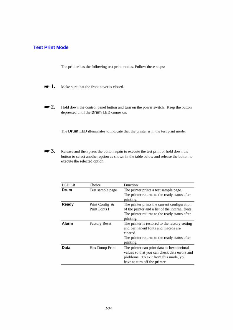
1-34
Test Print Mode
The printer has the following test print modes. Follow these steps:
���� 1. Make sure that the front cover is closed.
���� 2. Hold down the control panel button and turn on the power switch. Keep the buttondepressed until the Drum LED comes on.
The Drum LED illuminates to indicate that the printer is in the test print mode.
���� 3. Release and then press the button again to execute the test print or hold down thebutton to select another option as shown in the table below and release the button toexecute the selected option.
LED Lit Choice FunctionDrum Test sample page The printer prints a test sample page.
The printer returns to the ready status afterprinting.
Ready Print Config &Print Fonts I
The printer prints the current configurationof the printer and a list of the internal fonts.The printer returns to the ready status afterprinting.
Alarm Factory Reset The printer is restored to the factory settingand permanent fonts and macros arecleared.The printer returns to the ready status afterprinting.
Data Hex Dump Print The printer can print data as hexadecimalvalues so that you can check data errors andproblems. To exit from this mode, youhave to turn off the printer.
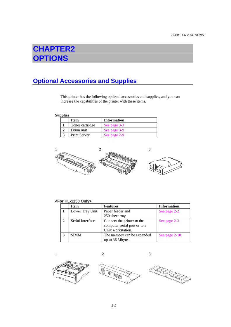
CHAPTER 2 OPTIONS
2-1
CHAPTER 2 OPTIONS
Optional Accessories and Supplies
This printer has the following optional accessories and supplies, and you canincrease the capabilities of the printer with these items.
SuppliesItem Information
1 Toner cartridge See page 3-32 Drum unit See page 3-93 Print Server See page 2-9
1 2 3
<For HL-1250 Only>Item Features Information
1 Lower Tray Unit Paper feeder and250 sheet tray
See page 2-2
2 Serial Interface Connect the printer to thecomputer serial port or to aUnix workstation.
See page 2-3
3 SIMM The memory can be expandedup to 36 Mbytes
See page 2-10.
1 2 3
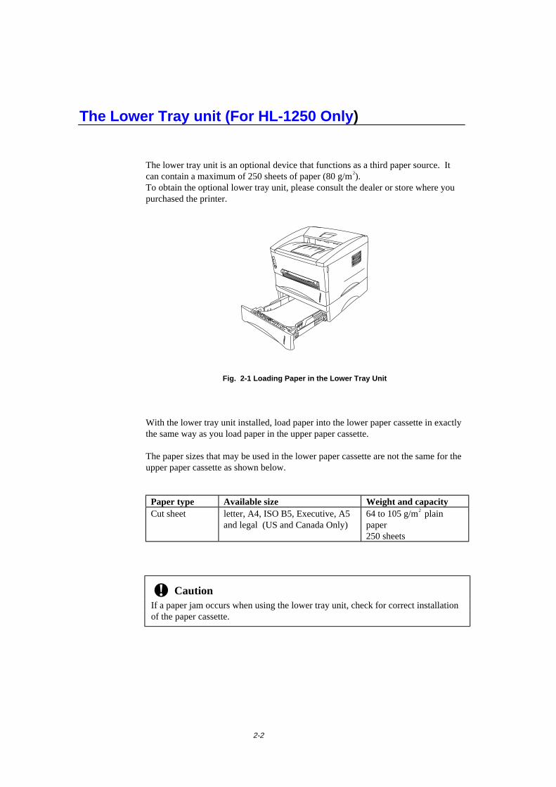
2-2
The Lower Tray unit (For HL-1250 Only)
The lower tray unit is an optional device that functions as a third paper source. Itcan contain a maximum of 250 sheets of paper (80 g/m2).To obtain the optional lower tray unit, please consult the dealer or store where youpurchased the printer.
Fig. 2-1 Loading Paper in the Lower Tray Unit
With the lower tray unit installed, load paper into the lower paper cassette in exactlythe same way as you load paper in the upper paper cassette.
The paper sizes that may be used in the lower paper cassette are not the same for theupper paper cassette as shown below.
Paper type Available size Weight and capacityCut sheet letter, A4, ISO B5, Executive, A5
and legal (US and Canada Only)64 to 105 g/m2 plainpaper250 sheets
! CautionIf a paper jam occurs when using the lower tray unit, check for correct installationof the paper cassette.

CHAPTER 2 OPTIONS
2-3
How to use the SERIAL INTERFACE (RS-100M)Connection (For HL-1250 Only)
To connect the printer to a DOS computer with a serial interface or to an AppleMacintosh computer with a serial interface, you need to install the optional serialinterface board (RS-100M). When you have installed the serial interface board, youcan share the printer between two computers (two IBM compatible PCs or one IBMcompatible PC and one Apple Macintosh) using the parallel and serial interfaces atthe same time. Automatic interface selection between the two connections is astandard feature.
✒ Note• The serial interface board for this printer is an option, but in some countries the
serial interface board may have been installed by either the factory or dealer.• The serial interface for Apple Macintosh (RS-422A) will only print at 300 dpi.
The serial interface board is installed onto the main controller board inside theprinter. For installation details, see the instruction guide which is provided with theserial interface board.
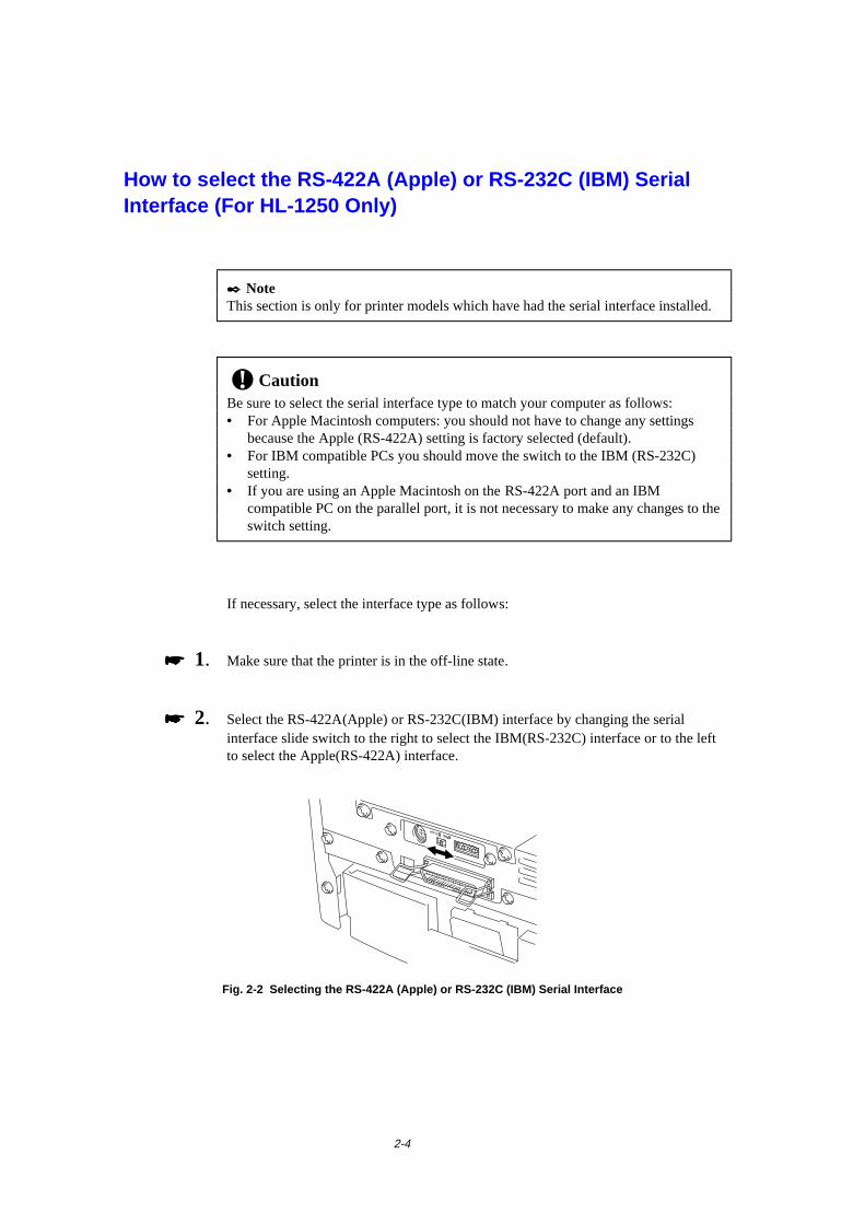
2-4
How to select the RS-422A (Apple) or RS-232C (IBM) SerialInterface (For HL-1250 Only)
✒ NoteThis section is only for printer models which have had the serial interface installed.
! CautionBe sure to select the serial interface type to match your computer as follows:• For Apple Macintosh computers: you should not have to change any settings
because the Apple (RS-422A) setting is factory selected (default).• For IBM compatible PCs you should move the switch to the IBM (RS-232C)
setting.• If you are using an Apple Macintosh on the RS-422A port and an IBM
compatible PC on the parallel port, it is not necessary to make any changes to theswitch setting.
If necessary, select the interface type as follows:
���� 1. Make sure that the printer is in the off-line state.
���� 2. Select the RS-422A(Apple) or RS-232C(IBM) interface by changing the serialinterface slide switch to the right to select the IBM(RS-232C) interface or to the leftto select the Apple(RS-422A) interface.
Fig. 2-2 Selecting the RS-422A (Apple) or RS-232C (IBM) Serial Interface
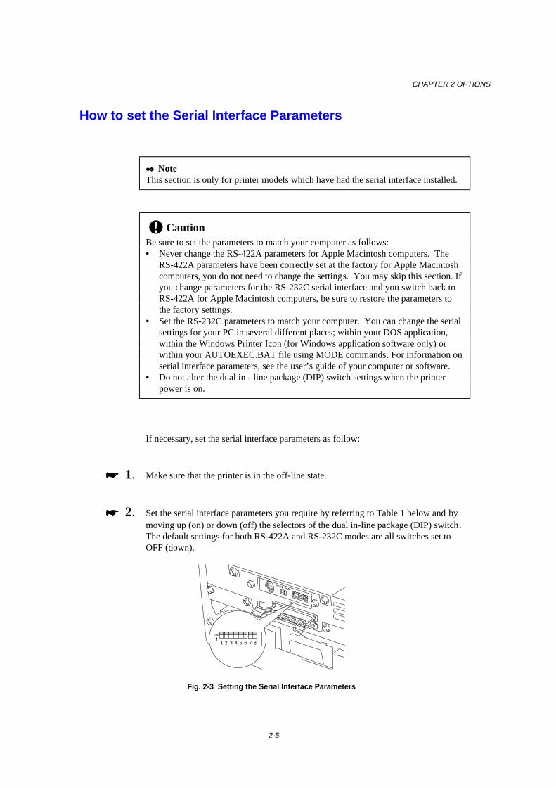
CHAPTER 2 OPTIONS
2-5
How to set the Serial Interface Parameters
✒ NoteThis section is only for printer models which have had the serial interface installed.
! CautionBe sure to set the parameters to match your computer as follows:• Never change the RS-422A parameters for Apple Macintosh computers. The
RS-422A parameters have been correctly set at the factory for Apple Macintoshcomputers, you do not need to change the settings. You may skip this section. Ifyou change parameters for the RS-232C serial interface and you switch back toRS-422A for Apple Macintosh computers, be sure to restore the parameters tothe factory settings.
• Set the RS-232C parameters to match your computer. You can change the serialsettings for your PC in several different places; within your DOS application,within the Windows Printer Icon (for Windows application software only) orwithin your AUTOEXEC.BAT file using MODE commands. For information onserial interface parameters, see the user’s guide of your computer or software.
• Do not alter the dual in - line package (DIP) switch settings when the printerpower is on.
If necessary, set the serial interface parameters as follow:
���� 1. Make sure that the printer is in the off-line state.
���� 2. Set the serial interface parameters you require by referring to Table 1 below and bymoving up (on) or down (off) the selectors of the dual in-line package (DIP) switch.The default settings for both RS-422A and RS-232C modes are all switches set toOFF (down).
ON
1 2 3 4 5 6 7 8
Fig. 2-3 Setting the Serial Interface Parameters
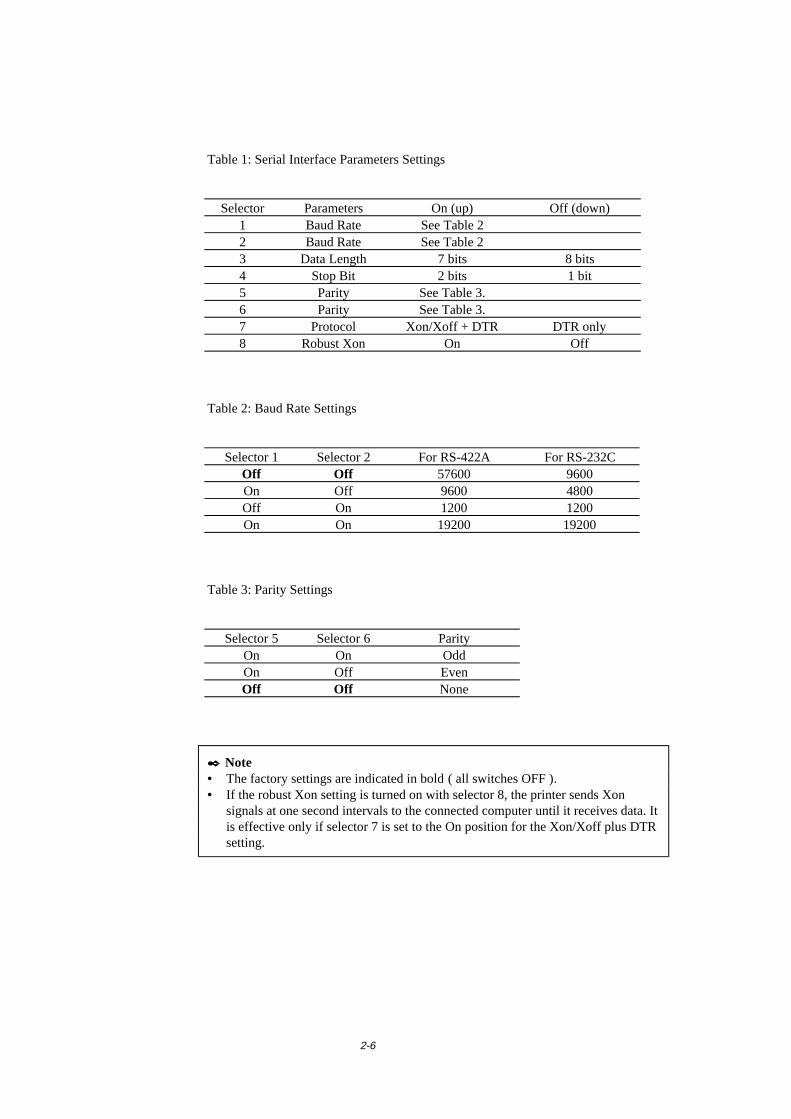
2-6
Table 1: Serial Interface Parameters Settings
Selector Parameters On (up) Off (down)1 Baud Rate See Table 22 Baud Rate See Table 23 Data Length 7 bits 8 bits4 Stop Bit 2 bits 1 bit5 Parity See Table 3.6 Parity See Table 3.7 Protocol Xon/Xoff + DTR DTR only8 Robust Xon On Off
Table 2: Baud Rate Settings
Selector 1 Selector 2 For RS-422A For RS-232COff Off 57600 9600On Off 9600 4800Off On 1200 1200On On 19200 19200
Table 3: Parity Settings
Selector 5 Selector 6 ParityOn On OddOn Off EvenOff Off None
✒ Note• The factory settings are indicated in bold ( all switches OFF ).• If the robust Xon setting is turned on with selector 8, the printer sends Xon
signals at one second intervals to the connected computer until it receives data. Itis effective only if selector 7 is set to the On position for the Xon/Xoff plus DTRsetting.

CHAPTER 2 OPTIONS
2-7
RS-100M Interface Connector
12
35 4
68 7
Fig. 2-4 Interface Connector
Pin Assignment
Pin No. SignalIBM(RS-232C) Apple(RS-422A)
1 DTR DTR2 DSR DSR3 TxD TxD-4 0V 0V5 RxD RxD-6 TxD+7 N.C.8 RxD+
2-8
How to connect the Serial Interface Cable
✒ NoteThis section is only for printer models which have had the serial interface installed.
You need a serial interface cable with an 8-pin, DIN-type connector to connect yourprinter and computer.
✒ Note• Consult your dealer for a serial interface cable.• If you are a Macintosh user, you can easily find the necessary cable at a local
computer store. Look for Apple serial cables labeled as “Macintosh toStyleWriter ” or “Macintosh to Personal LaserWriter LS” or the “AppleSystem Peripheral 8 Cable”. Do not purchase a serial cable labeled as “Straight-through” or “LocalTalk”.
• If you are a PC user, you need to purchase a special serial cable from yourdealer. If you have a 9-pin connector on your computer, look for a cable labeled“IBM AT to ImageWriter II” cable. If you have a 25-pin connector, look for acable labeled “DB25 to ImageWriter II.” These cables most likely would befound in the Apple Macintosh section at your computer dealer. For moreinformation about the interface specification, consult your dealer.
You can connect a parallel and a serial interface cable at the same time. The autointerface selection function allows you to share the printer with two computers. Todo this, connect the parallel interface cable and then connect the serial interfacecable as follows:

CHAPTER 2 OPTIONS
2-9
���� 1. Make sure that the power switch is turned off.
! CautionBe sure to turn off the power switch before connecting or disconnecting theinterface cables, or the printer may be damaged.
���� 2. Insert and secure the parallel interface connector from the computer into the parallelinterface port of the printer.
���� 3. Insert and secure the serial interface connector from the computer or Macintosh intothe serial interface port of the printer.
���� 4. Turn on the power switch.
2-10
What is the Brother print server (NC-2010p)
An optional Network print server Brother NC-2010p is available, which allows yourprinter to be connected to your network via the parallel interface.
Brother print servers allow multiple host computers to share a Brother printer on a10 Mbit Ethernet network. Any user can print their job as if the printer was directlyconnected to their computer. No special software is required on the host computersand users on DEC, UNIX, Novell, AppleTalk, LAN Server/Warp Server, WindowsNT, Windows 95/98, NetBIOS and Banyan VINES computers can simultaneouslyaccess the same printer.
Features
The Brother print servers offers the widest range of features in the industry,including:
• LAT, TCP/IP, Netware, AppleTalk, NetBIOS, Banyan VINES and DLC/LLCprotocols
• Network Operating System compatibility:
- Digital Equipment Corporation networks, including PATHWORKS andDECprint Server
- UNIX systems that support either the Berkeley lpr/lpd printing protocol,printing to a raw TCP port
- Novell Netware V2.15 or above, V3.xx, or V4.xx, including support forNetWare Directory Services (NDS)
- AppleTalk Phase 2- Windows NT4.0 and NT3.5x- IBM LAN Server V4.0 or above, or any earlier version that has IBM TCP/IP
V2.xx- Windows 95/98 (Peer-to-Peer or client mode)
• Very high performance• Superior network and printer management::
- BRAdmin and BRAdmin32 Windows-based Management utilities.- SNMP MIB I and MIB II over IP or IPX- Remote console management via DEC NCP, TELNET or NetWare.- HTTP web browser management capability
• Ipd-Plus feature for providing multiple services with custom setup and resetstrings plus text-to-PostScript conversion
• Flash memory for easy updating of firmware
CHAPTER 2 OPTIONS
2-11
How to add extra Memory (For HL-1250 Only)
The HL-1240 printer has 2 Mbyte of standard memory and is not able to beupgraded with additional memory.
The HL-1250 printer has 4 Mbyte of standard memory and a slot for optionaladditional memory. The memory can be expanded up to a total of 36 Mbytes byinstalling a commercially available single in-line memory module (SIMM).
Additional memory is useful and may be necessary if you are using the PageProtection function.
Minimum Memory Recommendation (including resident memory)
Page Protect = AUTO or Off
300 dpi 600 dpiLetter/A4 2 MB 2 MBLegal 2 MB 2 MB
Page Protection = Letter, A4, or Legal
300 dpi 600 dpiLetter/A4 2 MB 6 MBLegal 3 MB 6 MB
This printer can accept memory SIMM with the following specifications:
Speed 60 nsec - 80 nsecPin Type 72 pinHeight 35.00 mm (1.38”) or
lessOutput 32 bit or 36 bit
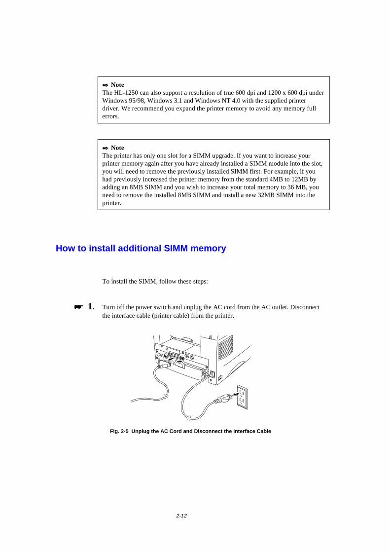
2-12
✒ NoteThe HL-1250 can also support a resolution of true 600 dpi and 1200 x 600 dpi underWindows 95/98, Windows 3.1 and Windows NT 4.0 with the supplied printerdriver. We recommend you expand the printer memory to avoid any memory fullerrors.
✒ NoteThe printer has only one slot for a SIMM upgrade. If you want to increase yourprinter memory again after you have already installed a SIMM module into the slot,you will need to remove the previously installed SIMM first. For example, if youhad previously increased the printer memory from the standard 4MB to 12MB byadding an 8MB SIMM and you wish to increase your total memory to 36 MB, youneed to remove the installed 8MB SIMM and install a new 32MB SIMM into theprinter.
How to install additional SIMM memory
To install the SIMM, follow these steps:
���� 1. Turn off the power switch and unplug the AC cord from the AC outlet. Disconnectthe interface cable (printer cable) from the printer.
Fig. 2-5 Unplug the AC Cord and Disconnect the Interface Cable
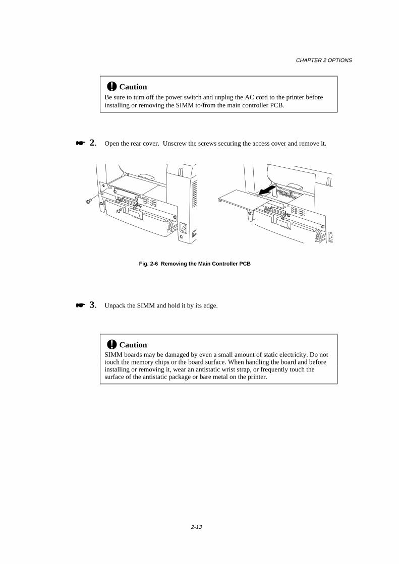
CHAPTER 2 OPTIONS
2-13
! CautionBe sure to turn off the power switch and unplug the AC cord to the printer beforeinstalling or removing the SIMM to/from the main controller PCB.
���� 2. Open the rear cover. Unscrew the screws securing the access cover and remove it.
Fig. 2-6 Removing the Main Controller PCB
���� 3. Unpack the SIMM and hold it by its edge.
! CautionSIMM boards may be damaged by even a small amount of static electricity. Do nottouch the memory chips or the board surface. When handling the board and beforeinstalling or removing it, wear an antistatic wrist strap, or frequently touch thesurface of the antistatic package or bare metal on the printer.
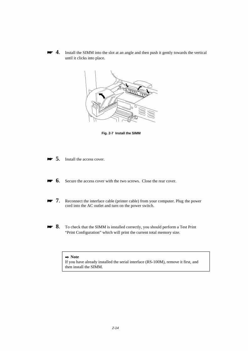
2-14
���� 4. Install the SIMM into the slot at an angle and then push it gently towards the verticaluntil it clicks into place.
Fig. 2-7 Install the SIMM
���� 5. Install the access cover.
���� 6. Secure the access cover with the two screws. Close the rear cover.
���� 7. Reconnect the interface cable (printer cable) from your computer. Plug the powercord into the AC outlet and turn on the power switch.
���� 8. To check that the SIMM is installed correctly, you should perform a Test Print“Print Configuration” which will print the current total memory size.
✒ NoteIf you have already installed the serial interface (RS-100M), remove it first, andthen install the SIMM.

CHAPTER 3 MAINTENANCE
3-1
CHAPTER 3 MAINTENANCE
The following are maintenance messages and appear on the LEDs. These messagesprompt you to replace each of the consumables before they run out.
LED maintenancemessage
Consumable toreplace
Approximate life How toreplace
Toner empty
Ready
AlarmPaper
TonerData
Drum
Toner cartridge 3,000 pages *(standard tonercartridge)
6,000 pages *(high capacity tonercartridge)
See 3-3
Drum life
Drum
Ready
AlarmPaper
TonerData
Drum unit Up to 20,000 pages * See 3-9
3-2
Periodic maintenance parts
To maintain print quality, the fixing unit should be replaced after printing thefollowing number of pages.
Item Approximate life To purchase replacementFixing unit 50,000 pages * Call customer supportSeparator pad holderassy
50,000 pages * Call customer support
Pick up roller assy 50,000 pages * Call customer support
* The actual number of printed pages may vary depending on your average type of print job and type of paper. The figures quoted are based upon 5% coverage per
page.
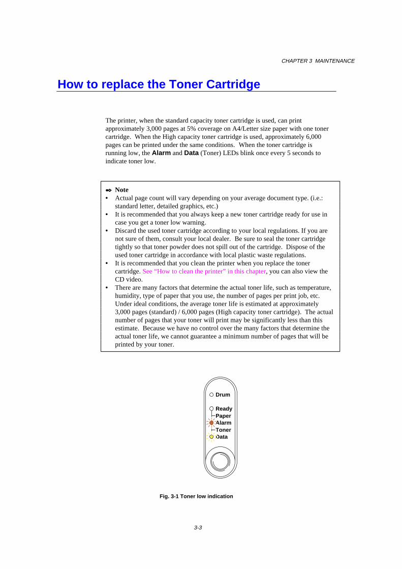
CHAPTER 3 MAINTENANCE
3-3
How to replace the Toner Cartridge
The printer, when the standard capacity toner cartridge is used, can printapproximately 3,000 pages at 5% coverage on A4/Letter size paper with one tonercartridge. When the High capacity toner cartridge is used, approximately 6,000pages can be printed under the same conditions. When the toner cartridge isrunning low, the Alarm and Data (Toner) LEDs blink once every 5 seconds toindicate toner low.
✒ Note• Actual page count will vary depending on your average document type. (i.e.:
standard letter, detailed graphics, etc.)• It is recommended that you always keep a new toner cartridge ready for use in
case you get a toner low warning.• Discard the used toner cartridge according to your local regulations. If you are
not sure of them, consult your local dealer. Be sure to seal the toner cartridgetightly so that toner powder does not spill out of the cartridge. Dispose of theused toner cartridge in accordance with local plastic waste regulations.
• It is recommended that you clean the printer when you replace the tonercartridge. See “How to clean the printer” in this chapter, you can also view theCD video.
• There are many factors that determine the actual toner life, such as temperature,humidity, type of paper that you use, the number of pages per print job, etc.Under ideal conditions, the average toner life is estimated at approximately3,000 pages (standard) / 6,000 pages (High capacity toner cartridge). The actualnumber of pages that your toner will print may be significantly less than thisestimate. Because we have no control over the many factors that determine theactual toner life, we cannot guarantee a minimum number of pages that will beprinted by your toner.
Ready
AlarmPaper
TonerData
Drum
Fig. 3-1 Toner low indication
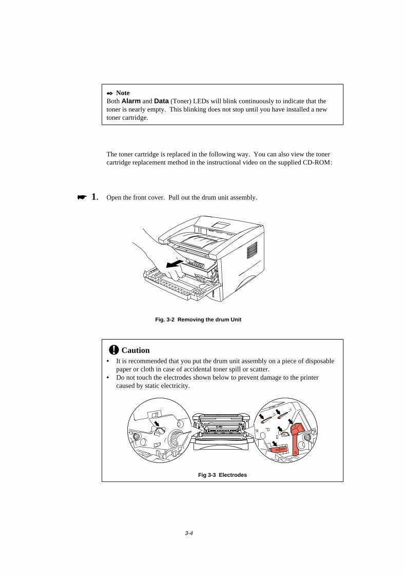
3-4
✒ NoteBoth Alarm and Data (Toner) LEDs will blink continuously to indicate that thetoner is nearly empty. This blinking does not stop until you have installed a newtoner cartridge.
The toner cartridge is replaced in the following way. You can also view the tonercartridge replacement method in the instructional video on the supplied CD-ROM:
���� 1. Open the front cover. Pull out the drum unit assembly.
Fig. 3-2 Removing the drum Unit
! Caution• It is recommended that you put the drum unit assembly on a piece of disposable
paper or cloth in case of accidental toner spill or scatter.• Do not touch the electrodes shown below to prevent damage to the printer
caused by static electricity.
Fig 3-3 Electrodes

CHAPTER 3 MAINTENANCE
3-5
���� 2. Place the drum unit assembly containing the old toner cartridge on a flat, horizontalsurface, and pull the toner cartridge out of the drum unit assembly while pushing thelock lever down with your right hand.
Fig. 3-4 Removing the old toner cartridge
! CautionHandle the toner cartridge carefully. If toner scatters on your hands or clothes, wipeor wash it off with cold water immediately.
���� 3. Unpack the new toner cartridge, gently rock it from side to side 5 or 6 times keepingit horizontal.
Fig. 3-5 Rocking the toner cartridge
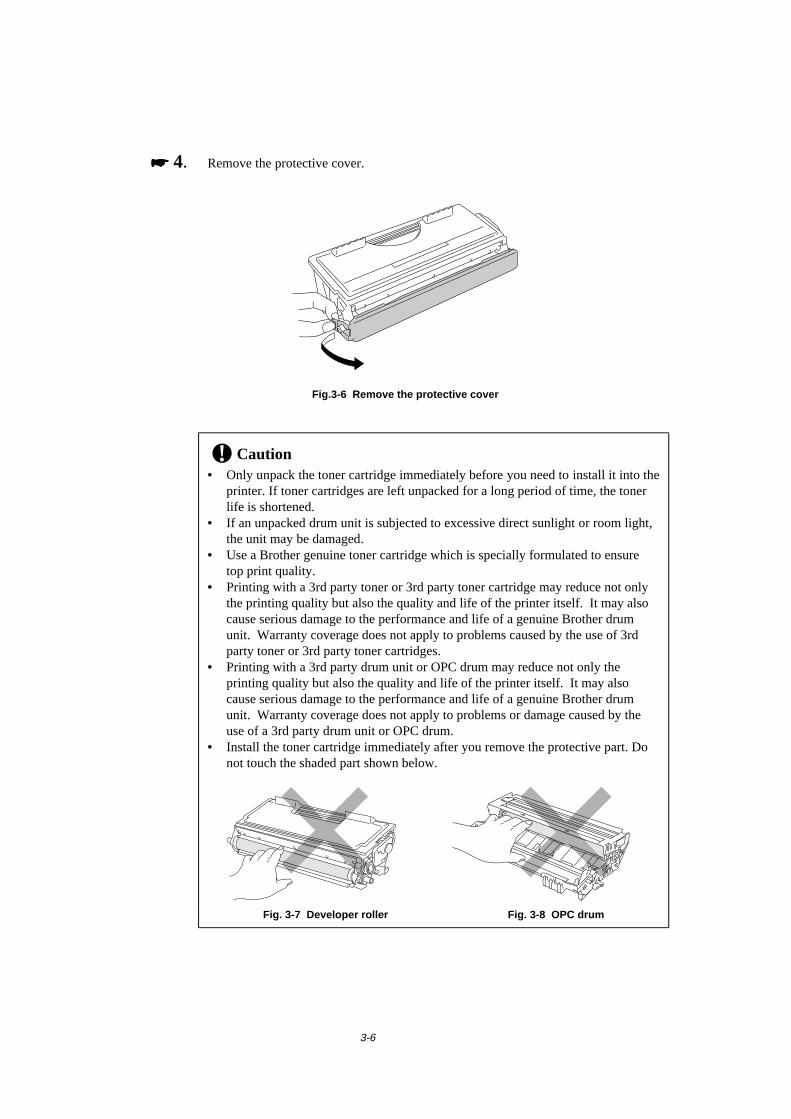
3-6
���� 4. Remove the protective cover.
Fig.3-6 Remove the protective cover
! Caution• Only unpack the toner cartridge immediately before you need to install it into the
printer. If toner cartridges are left unpacked for a long period of time, the tonerlife is shortened.
• If an unpacked drum unit is subjected to excessive direct sunlight or room light,the unit may be damaged.
• Use a Brother genuine toner cartridge which is specially formulated to ensuretop print quality.
• Printing with a 3rd party toner or 3rd party toner cartridge may reduce not onlythe printing quality but also the quality and life of the printer itself. It may alsocause serious damage to the performance and life of a genuine Brother drumunit. Warranty coverage does not apply to problems caused by the use of 3rdparty toner or 3rd party toner cartridges.
• Printing with a 3rd party drum unit or OPC drum may reduce not only theprinting quality but also the quality and life of the printer itself. It may alsocause serious damage to the performance and life of a genuine Brother drumunit. Warranty coverage does not apply to problems or damage caused by theuse of a 3rd party drum unit or OPC drum.
• Install the toner cartridge immediately after you remove the protective part. Donot touch the shaded part shown below.
Fig. 3-7 Developer roller Fig. 3-8 OPC drum
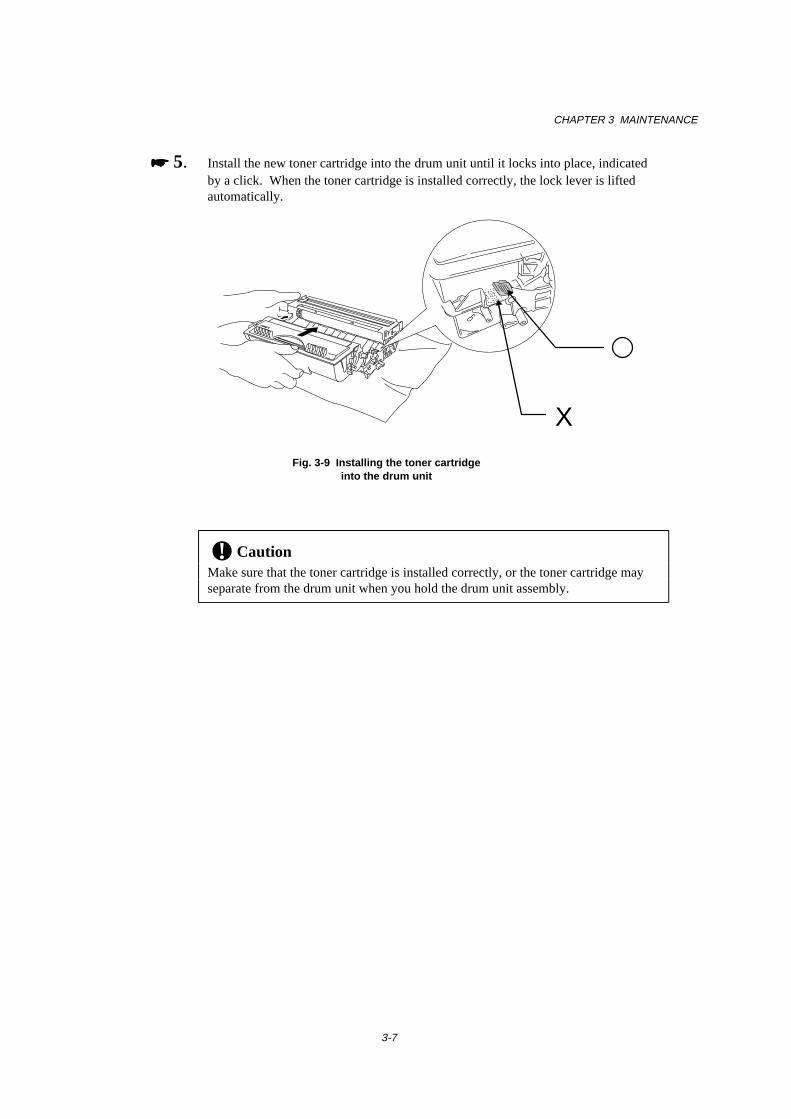
CHAPTER 3 MAINTENANCE
3-7
���� 5. Install the new toner cartridge into the drum unit until it locks into place, indicatedby a click. When the toner cartridge is installed correctly, the lock lever is liftedautomatically.
Fig. 3-9 Installing the toner cartridgeinto the drum unit
! CautionMake sure that the toner cartridge is installed correctly, or the toner cartridge mayseparate from the drum unit when you hold the drum unit assembly.
X
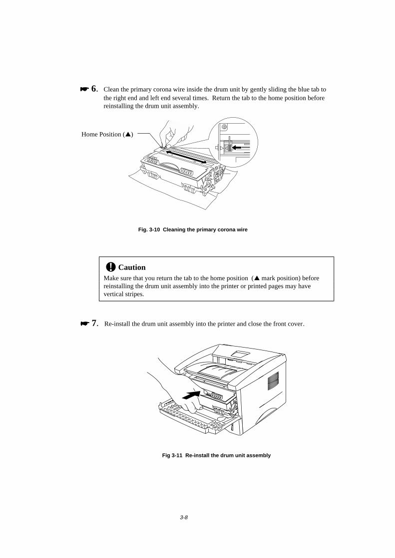
3-8
���� 6. Clean the primary corona wire inside the drum unit by gently sliding the blue tab tothe right end and left end several times. Return the tab to the home position beforereinstalling the drum unit assembly.
Fig. 3-10 Cleaning the primary corona wire
! CautionMake sure that you return the tab to the home position (▲ mark position) beforereinstalling the drum unit assembly into the printer or printed pages may havevertical stripes.
���� 7. Re-install the drum unit assembly into the printer and close the front cover.
Fig 3-11 Re-install the drum unit assembly
Home Position (▲)
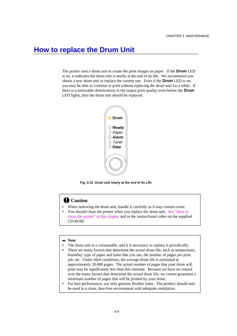
CHAPTER 3 MAINTENANCE
3-9
How to replace the Drum Unit
The printer uses a drum unit to create the print images on paper. If the Drum LEDis on, it indicates the drum unit is nearly at the end of its life. We recommend youobtain a new drum unit to replace the current one. Even if the Drum LED is on,you may be able to continue to print without replacing the drum unit for a while. Ifthere is a noticeable deterioration in the output print quality even before the DrumLED lights, then the drum unit should be replaced.
Drum
Ready
AlarmPaper
TonerData
Fig. 3-12 Drum unit nearly at the end of its Life
! Caution• When removing the drum unit, handle it carefully as it may contain toner.• You should clean the printer when you replace the drum unit. See “How to
clean the printer” in this chapter and in the instructional video on the suppliedCD-ROM.
✒ Note• The drum unit is a consumable, and it is necessary to replace it periodically.• There are many factors that determine the actual drum life, such as temperature,
humidity, type of paper and toner that you use, the number of pages per printjob, etc. Under ideal conditions, the average drum life is estimated atapproximately 20,000 pages. The actual number of pages that your drum willprint may be significantly less than this estimate. Because we have no controlover the many factors that determine the actual drum life, we cannot guarantee aminimum number of pages that will be printed by your drum.
• For best performance, use only genuine Brother toner. The product should onlybe used in a clean, dust-free environment with adequate ventilation.
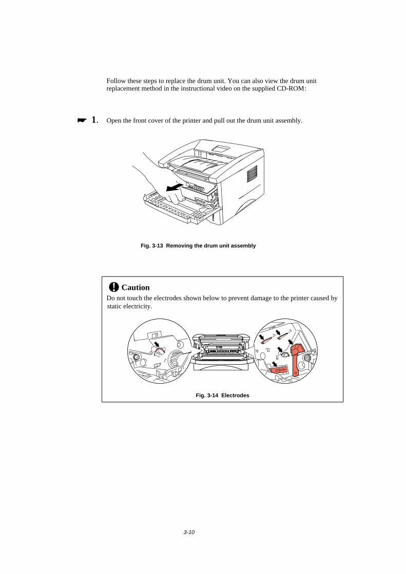
3-10
Follow these steps to replace the drum unit. You can also view the drum unitreplacement method in the instructional video on the supplied CD-ROM:
���� 1. Open the front cover of the printer and pull out the drum unit assembly.
Fig. 3-13 Removing the drum unit assembly
! CautionDo not touch the electrodes shown below to prevent damage to the printer caused bystatic electricity.
Fig. 3-14 Electrodes
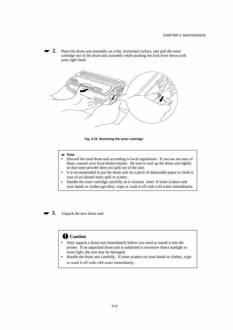
CHAPTER 3 MAINTENANCE
3-11
���� 2. Place the drum unit assembly on a flat, horizontal surface, and pull the tonercartridge out of the drum unit assembly while pushing the lock lever down withyour right hand.
Fig. 3-15 Removing the toner cartridge
✒ Note• Discard the used drum unit according to local regulations. If you are not sure of
them, consult your local dealer/retailer. Be sure to seal up the drum unit tightlyso that toner powder does not spill out of the unit.
• It is recommended to put the drum unit on a piece of disposable paper or cloth incase of accidental toner spill or scatter.
• Handle the toner cartridge carefully as it contains toner. If toner scatters andyour hands or clothes get dirty, wipe or wash it off with cold water immediately.
���� 3. Unpack the new drum unit.
! Caution• Only unpack a drum unit immediately before you need to install it into the
printer. If an unpacked drum unit is subjected to excessive direct sunlight orroom light, the unit may be damaged.
• Handle the drum unit carefully. If toner scatters on your hands or clothes, wipe
or wash it off with cold water immediately.
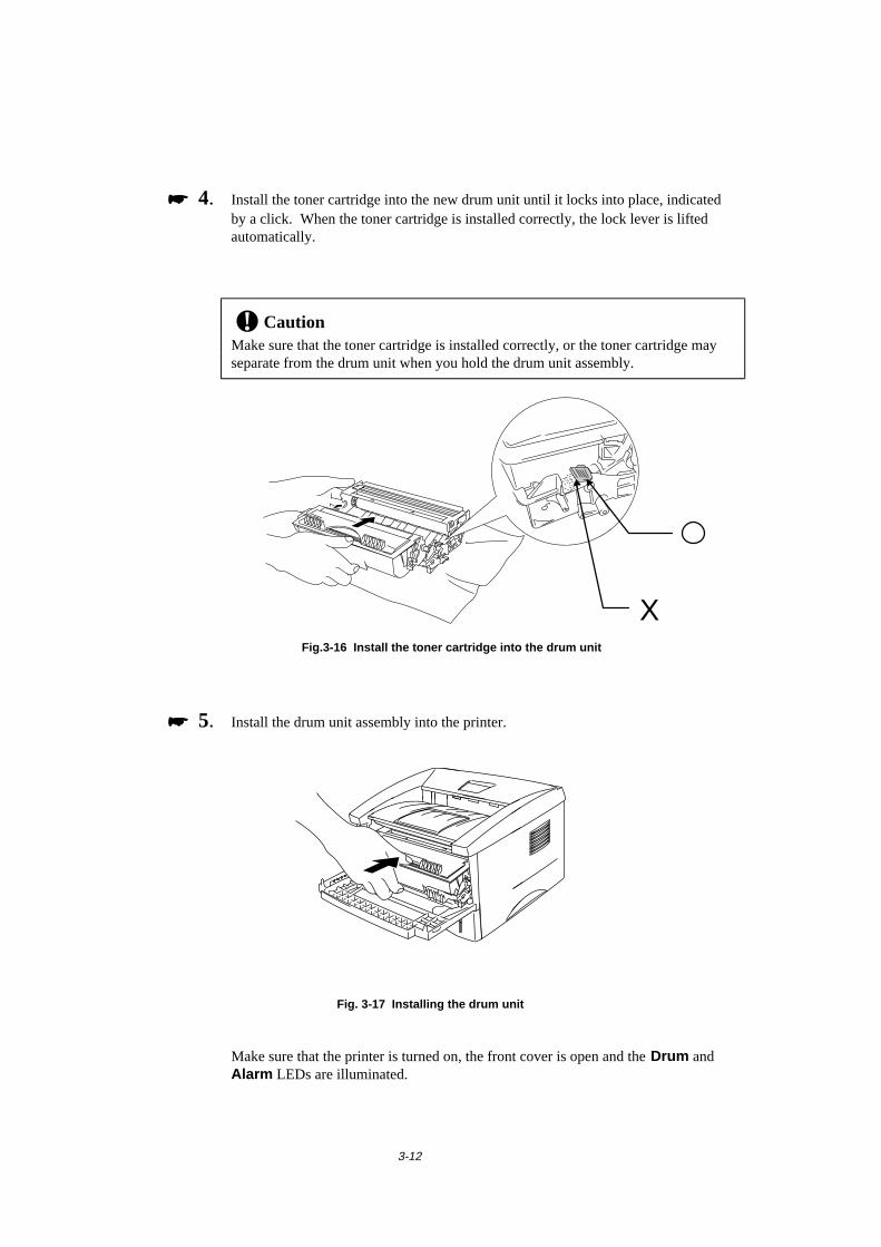
3-12
���� 4. Install the toner cartridge into the new drum unit until it locks into place, indicatedby a click. When the toner cartridge is installed correctly, the lock lever is liftedautomatically.
! CautionMake sure that the toner cartridge is installed correctly, or the toner cartridge mayseparate from the drum unit when you hold the drum unit assembly.
Fig.3-16 Install the toner cartridge into the drum unit
���� 5. Install the drum unit assembly into the printer.
Fig. 3-17 Installing the drum unit
Make sure that the printer is turned on, the front cover is open and the Drum andAlarm LEDs are illuminated.
X
CHAPTER 3 MAINTENANCE
3-13
����
���� 6. Reset the page counter referring to the instructions supplied with the new drum unit.
! CautionDo not reset the page counter when you replace the toner cartridge only.
���� 7. Close the front cover.
���� 8. Make sure that the Drum LED is now off.
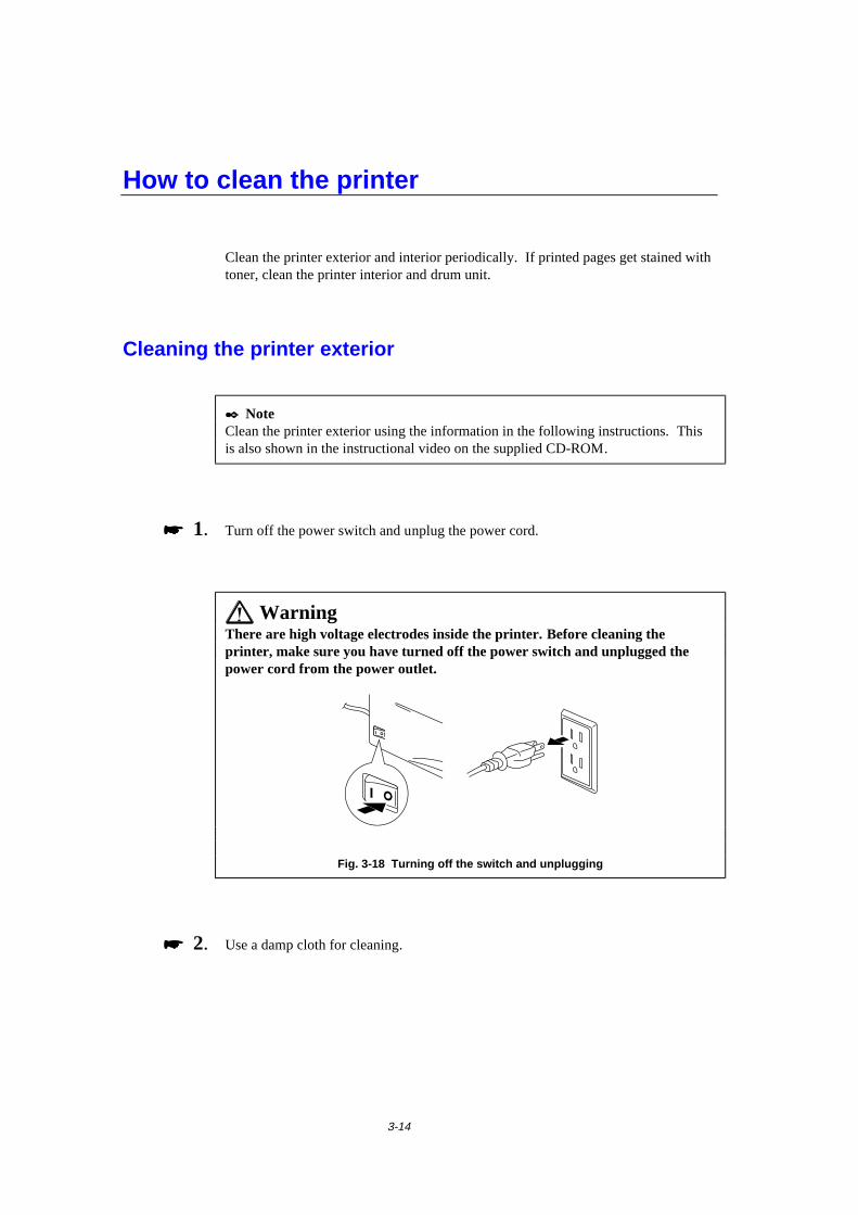
3-14
How to clean the printer
Clean the printer exterior and interior periodically. If printed pages get stained withtoner, clean the printer interior and drum unit.
Cleaning the printer exterior
✒ NoteClean the printer exterior using the information in the following instructions. Thisis also shown in the instructional video on the supplied CD-ROM.
���� 1. Turn off the power switch and unplug the power cord.
WarningThere are high voltage electrodes inside the printer. Before cleaning theprinter, make sure you have turned off the power switch and unplugged thepower cord from the power outlet.
Fig. 3-18 Turning off the switch and unplugging
���� 2. Use a damp cloth for cleaning.
CHAPTER 3 MAINTENANCE
3-15
! CautionUse water or neutral detergents for cleaning. Cleaning with volatile liquids such asthinners or benzene will damage the surface of the printer.
���� 3. Wipe dirt and dust away from the printer exterior with the damp cloth and allow theprinter to dry completely before turning the power on again.
���� 4. Plug in the power cord.
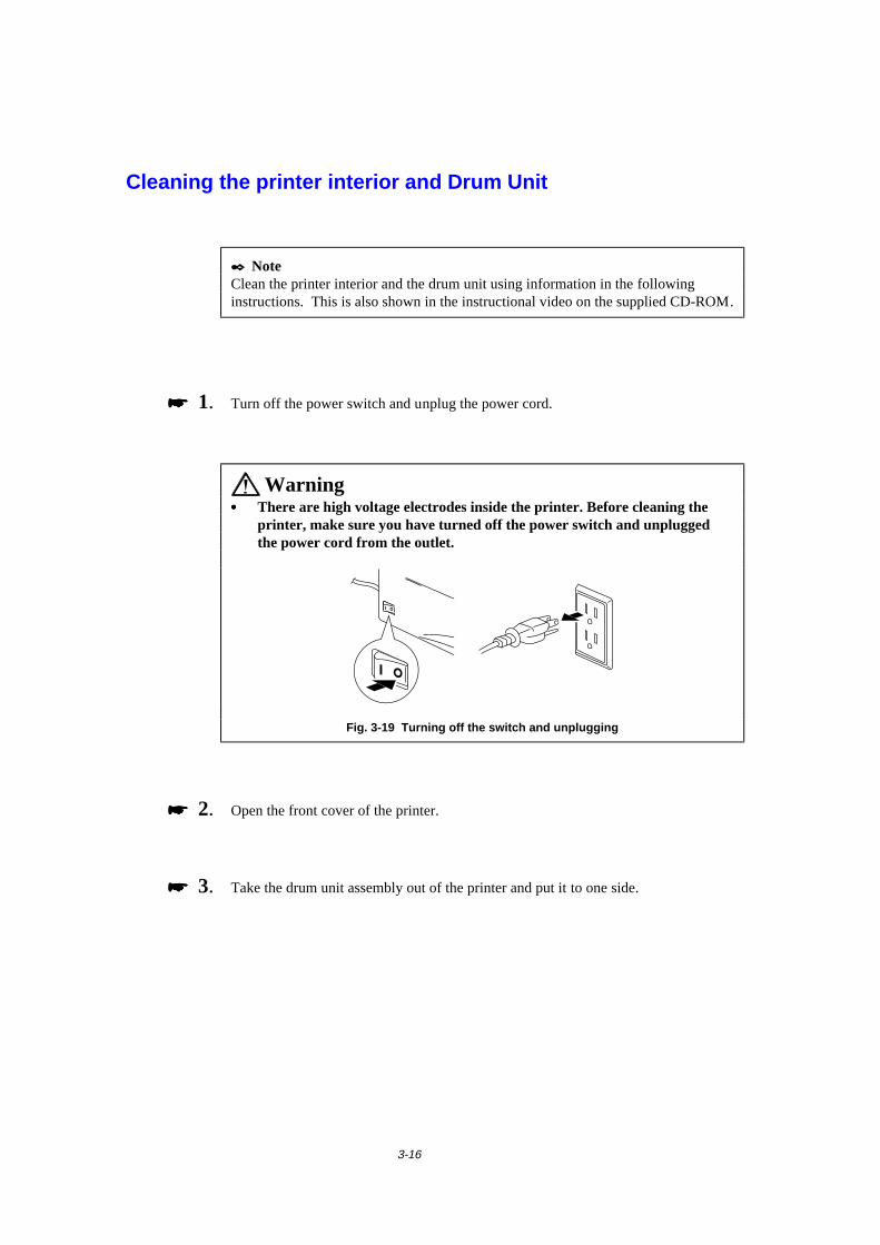
3-16
Cleaning the printer interior and Drum Unit
✒ NoteClean the printer interior and the drum unit using information in the followinginstructions. This is also shown in the instructional video on the supplied CD-ROM.
���� 1. Turn off the power switch and unplug the power cord.
Warning• • • • There are high voltage electrodes inside the printer. Before cleaning the
printer, make sure you have turned off the power switch and unpluggedthe power cord from the outlet.
Fig. 3-19 Turning off the switch and unplugging
���� 2. Open the front cover of the printer.
���� 3. Take the drum unit assembly out of the printer and put it to one side.

CHAPTER 3 MAINTENANCE
3-17
WarningAfter you have just used the printer, some internal parts of the printer areextremely hot. When you open the front cover of the printer, never touch theshaded parts shown in the following illustration.
High Temperature High Temperature
Front view Rear view
Fig. 3-20 Inside the printer
���� 4. Gently wipe the scanner window with a soft dry cloth.
Fig. 3-21 Cleaning the scanner window
! Caution• Do not touch the scanner window with your fingers.• Do not wipe the scanner window with cleaning alcohol (isophorol).• Handle the drum unit carefully as it contains toner. If toner scatters and your
hands or cloths get dirty, wipe or wash it off with water immediately.
✒ NoteIt is recommended to put the drum unit on a piece of disposable paper or cloth incase of accidental toner spill or scatter.
Scanner Window

3-18
���� 5. Clean the primary corona wire inside the drum unit by gently sliding the tab to theright hand end and left hand end several times.
Fig. 3-22 Cleaning the primary corona wire
���� 6. Return the tab to the home position (▲ mark position) before reinstalling the drumunit assembly into the printer.
! CautionBe sure to position the tab at the home position, or printed pages may have verticalstripes.
���� 7. Install the drum unit assembly into the printer.See the section “How to replace the Drum unit” earlier in this Chapter.
���� 8. Close the front cover.
���� 9. Plug in the power cord and turn on the power switch.
Home Position (▲)
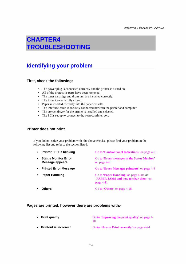
CHAPTER 4 TROUBLESHOOTING
4-1
CHAPTER 4 TROUBLESHOOTING
Identifying your problem
First, check the following:
• The power plug is connected correctly and the printer is turned on.• All of the protective parts have been removed.• The toner cartridge and drum unit are installed correctly.• The Front Cover is fully closed.• Paper is inserted correctly into the paper cassette.• The interface cable is securely connected between the printer and computer.• The correct driver for the printer is installed and selected.• The PC is set up to connect to the correct printer port.
Printer does not print
If you did not solve your problem with the above checks, please find your problem in thefollowing list and refer to the section listed.
• • • • Printer LED is blinking Go to ‘Control Panel Indications’ on page 4-2
• • • • Status Monitor ErrorMessage appears
Go to ‘Error messages in the Status Monitor’on page 4-6
• • • • Printed Error Message Go to ‘Error Messages printouts’ on page 4-8
• • • • Paper Handling Go to ‘Paper Handling’ on page 4-10, or‘PAPER JAMS and how to clear them’ onpage 4-11
• • • • Others Go to ‘Others’ on page 4-16.
Pages are printed, however there are problems with:-
• • • • Print quality Go to ‘Improving the print quality’ on page 4-18
• • • • Printout is incorrect Go to ‘How to Print correctly’ on page 4-24
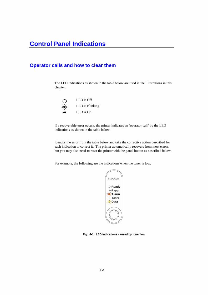
4-2
Control Panel Indications
Operator calls and how to clear them
The LED indications as shown in the table below are used in the illustrations in thischapter.
❍ LED is Off
LED is Blinking
� LED is On
If a recoverable error occurs, the printer indicates an ‘operator call’ by the LEDindications as shown in the table below.
Identify the error from the table below and take the corrective action described foreach indication to correct it. The printer automatically recovers from most errors,but you may also need to reset the printer with the panel button as described below.
For example, the following are the indications when the toner is low.
Ready
AlarmPaper
TonerData
Drum
Fig. 4-1 LED indications caused by toner low
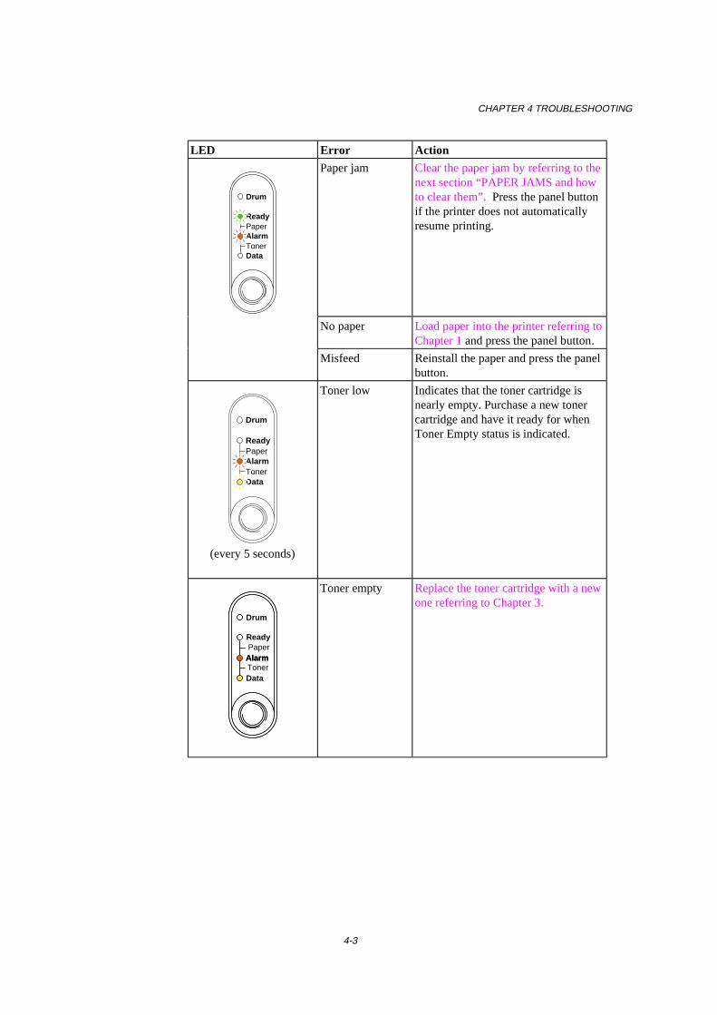
CHAPTER 4 TROUBLESHOOTING
4-3
LED Error Action
Ready
AlarmPaper
TonerData
Drum
Paper jam Clear the paper jam by referring to thenext section “PAPER JAMS and howto clear them”. Press the panel buttonif the printer does not automaticallyresume printing.
No paper Load paper into the printer referring toChapter 1 and press the panel button.
Misfeed Reinstall the paper and press the panelbutton.
Ready
AlarmPaper
TonerData
Drum
(every 5 seconds)
Toner low Indicates that the toner cartridge isnearly empty. Purchase a new tonercartridge and have it ready for whenToner Empty status is indicated.
Alarm
Ready
AlarmPaper
TonerData
Drum
Toner empty Replace the toner cartridge with a newone referring to Chapter 3.
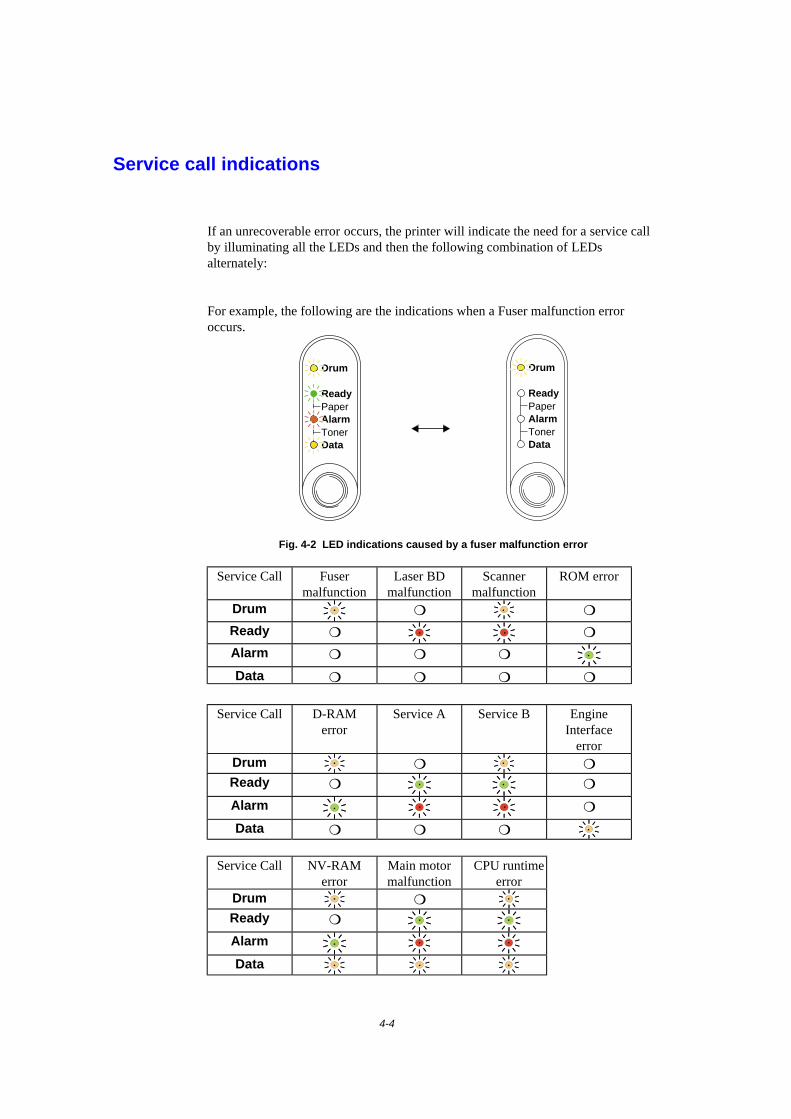
4-4
Service call indications
If an unrecoverable error occurs, the printer will indicate the need for a service callby illuminating all the LEDs and then the following combination of LEDsalternately:
For example, the following are the indications when a Fuser malfunction erroroccurs.
Ready
AlarmPaper
TonerData
Drum
Ready
AlarmPaper
TonerData
Drum
Fig. 4-2 LED indications caused by a fuser malfunction error
Service Call Fusermalfunction
Laser BDmalfunction
Scannermalfunction
ROM error
Drum ❍ ❍
Ready ❍ ❍
Alarm ❍ ❍ ❍
Data ❍ ❍ ❍ ❍
Service Call D-RAMerror
Service A Service B EngineInterface
errorDrum ❍ ❍
Ready ❍ ❍
Alarm ❍
Data ❍ ❍ ❍
Service Call NV-RAMerror
Main motormalfunction
CPU runtimeerror
Drum ❍
Ready ❍
Alarm
Data

CHAPTER 4 TROUBLESHOOTING
4-5
If you see any of these service call indications, turn off the power switch, wait a fewseconds, then turn it on and try to print again.
If you cannot clear the error and see the same service call indication after turning onthe printer, consult your dealer or our authorized service representative. Please notethe indication and report the error status and problem by referring to the above table.
✒ NoteEnsure that the front cover is fully closed before reporting a Service call.

4-6
Error messages in the Status Monitor
The Status Monitor will report problems with the printer as defined in the followingtable. Take the corrective actions for the error message the Status Monitor reports.
Error message ActionCOVER OPEN • Close the front cover of the printer.NO PAPER orMISFEED
• The paper cassette may be out of paper or not properlyinstalled. If it is empty, load a new stack of paper into thepaper cassette.
• If there is paper in the paper cassette, make sure it is straight.If the paper is curled, you should straighten it before printing.Sometimes it is helpful to remove the paper, turn the stackover and put it back into the paper cassette.
• Reduce the amount of paper in the paper cassette, then tryagain.
• Make sure that you use paper that meets Brother’srecommended paper specifications. See “What kind of papercan I use” in Chapter 1.
PAPER JAM • Refer to ‘PAPER JAMS and how clear them’.TONER LOW • Purchase a new toner cartridge and have it ready for when the
Toner Empty status is indicated.TONER EMPTY • Refer to ‘How to replace the Toner cartridge’ in Chapter 3 or
view the instructional video on the CD-ROM.PRINT OVERRUN • Press the panel button to print the data remaining in the
printer.• If this does not clear the error, reduce the complexity of your
document or reduce the print resolution.
(For HL-1250 Only)• Expand the printer memory by adding a commercially
available SIMM. Refer to ‘How to add extra Memory’ inChapter 2. Set page protection to ON by using the suppliedWindows driver or RPC program.
• Change the following settings in the supplied Windows driverand try again. The best combination of settings below willvary depending on your document.
Graphics ModeTrue TypeTM modeUse Printer True TypeTM Fonts
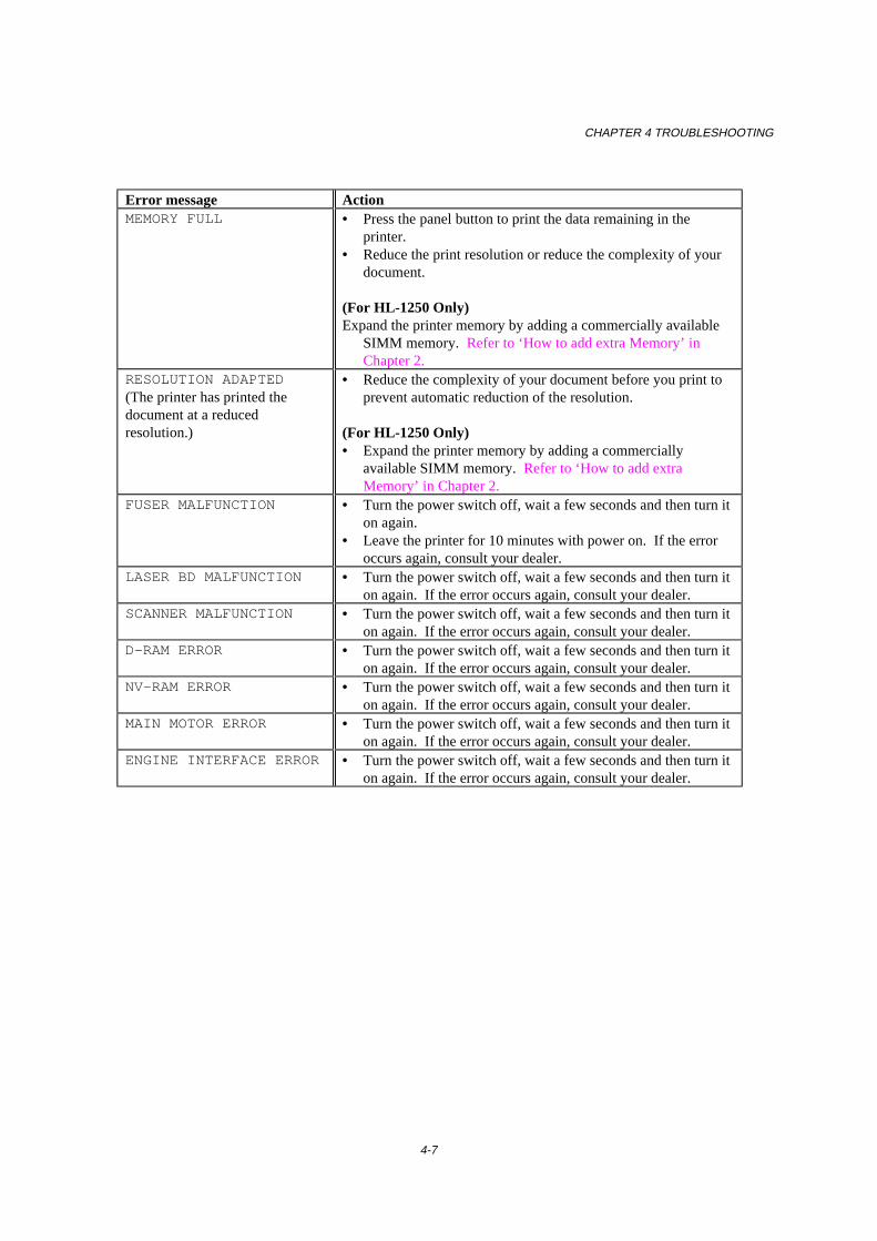
CHAPTER 4 TROUBLESHOOTING
4-7
Error message ActionMEMORY FULL • Press the panel button to print the data remaining in the
printer.• Reduce the print resolution or reduce the complexity of your
document.
(For HL-1250 Only)Expand the printer memory by adding a commercially available
SIMM memory. Refer to ‘How to add extra Memory’ inChapter 2.
RESOLUTION ADAPTED(The printer has printed thedocument at a reducedresolution.)
• Reduce the complexity of your document before you print toprevent automatic reduction of the resolution.
(For HL-1250 Only)• Expand the printer memory by adding a commercially
available SIMM memory. Refer to ‘How to add extraMemory’ in Chapter 2.
FUSER MALFUNCTION • Turn the power switch off, wait a few seconds and then turn iton again.
• Leave the printer for 10 minutes with power on. If the erroroccurs again, consult your dealer.
LASER BD MALFUNCTION • Turn the power switch off, wait a few seconds and then turn iton again. If the error occurs again, consult your dealer.
SCANNER MALFUNCTION • Turn the power switch off, wait a few seconds and then turn iton again. If the error occurs again, consult your dealer.
D-RAM ERROR • Turn the power switch off, wait a few seconds and then turn iton again. If the error occurs again, consult your dealer.
NV-RAM ERROR • Turn the power switch off, wait a few seconds and then turn iton again. If the error occurs again, consult your dealer.
MAIN MOTOR ERROR • Turn the power switch off, wait a few seconds and then turn iton again. If the error occurs again, consult your dealer.
ENGINE INTERFACE ERROR • Turn the power switch off, wait a few seconds and then turn iton again. If the error occurs again, consult your dealer.
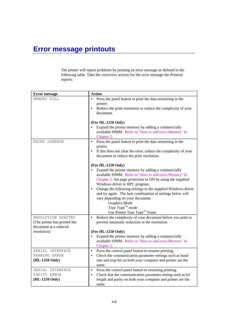
4-8
Error message printouts
The printer will report problems by printing an error message as defined in thefollowing table. Take the corrective actions for the error message the Printoutreports.
Error message ActionMEMORY FULL • Press the panel button to print the data remaining in the
printer.• Reduce the print resolution or reduce the complexity of your
document.
(For HL-1250 Only)• Expand the printer memory by adding a commercially
available SIMM. Refer to ‘How to add extra Memory’ inChapter 2.
PRINT OVERRUN • Press the panel button to print the data remaining in theprinter.
• If this does not clear the error, reduce the complexity of yourdocument or reduce the print resolution.
(For HL-1250 Only)• Expand the printer memory by adding a commercially
available SIMM. Refer to ‘How to add extra Memory’ inChapter 2. Set page protection to ON by using the suppliedWindows driver or RPC program.
• Change the following settings in the supplied Windows driverand try again. The best combination of settings below willvary depending on your document.
Graphics ModeTrue TypeTM modeUse Printer True TypeTM Fonts
RESOLUTION ADAPTED(The printer has printed thedocument at a reducedresolution)
• Reduce the complexity of your document before you print toprevent automatic reduction in the resolution.
(For HL-1250 Only)• Expand the printer memory by adding a commercially
available SIMM. Refer to ‘How to add extra Memory’ inChapter 2.
SERIAL INTERFACEFRAMING ERROR(HL-1250 Only)
• Press the control panel button to resume printing.• Check the communication parameter settings such as baud
rate and stop bit on both your computer and printer are thesame.
SERIAL INTERFACEPARITY ERROR(HL-1250 Only)
• Press the control panel button to resuming printing.• Check that the communication parameter setting such as bit
length and parity on both your computer and printer are thesame.

CHAPTER 4 TROUBLESHOOTING
4-9
Error Message ActionSERIAL INTERFACEOVERRUN ERROR(HL-1250 Only)
• Press the control panel button to resume printing.• If the error occurs again, the interface’s hardware may be
damaged. Please consult your dealer.SERIAL INTERFACE INPUTBUFFER OVERFLOW(HL-1250 Only)
• Press the control panel button to resume printing.• Check the communication parameter settings such as the
handshake protocols on both your computer and printer.• If the error occurs again, the interface hardware may be
damaged, consult your dealer.
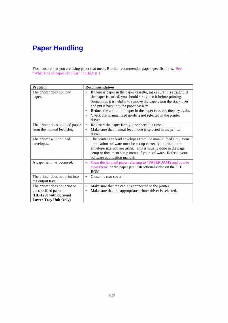
4-10
Paper Handling
First, ensure that you are using paper that meets Brother recommended paper specifications. See“What kind of paper can I use” in Chapter 1.
Problem RecommendationThe printer does not loadpaper.
• If there is paper in the paper cassette, make sure it is straight. Ifthe paper is curled, you should straighten it before printing.Sometimes it is helpful to remove the paper, turn the stack overand put it back into the paper cassette.
• Reduce the amount of paper in the paper cassette, then try again.• Check that manual feed mode is not selected in the printer
driver.The printer does not load paperfrom the manual feed slot.
• Re-insert the paper firmly, one sheet at a time.• Make sure that manual feed mode is selected in the printer
driver.The printer will not loadenvelopes.
• The printer can load envelopes from the manual feed slot. Yourapplication software must be set up correctly to print on theenvelope size you are using. This is usually done in the pagesetup or document setup menu of your software. Refer to yoursoftware application manual.
A paper jam has occurred. • Clear the jammed paper referring to “PAPER JAMS and how toclear them” or the paper jam instructional video on the CD-ROM.
The printer does not print intothe output tray.
• Close the rear cover.
The printer does not print onthe specified paper.(HL-1250 with optionalLower Tray Unit Only)
• Make sure that the cable is connected to the printer• Make sure that the appropriate printer driver is selected.
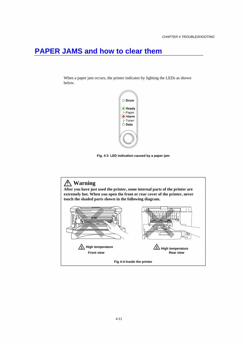
CHAPTER 4 TROUBLESHOOTING
4-11
PAPER JAMS and how to clear them
When a paper jam occurs, the printer indicates by lighting the LEDs as shownbelow.
Ready
AlarmPaper
TonerData
Drum
Fig. 4-3 LED indication caused by a paper jam
WarningAfter you have just used the printer, some internal parts of the printer areextremely hot. When you open the front or rear cover of the printer, nevertouch the shaded parts shown in the following diagram.
High temperature High temperature Front view Rear view
Fig 4-4 Inside the printer
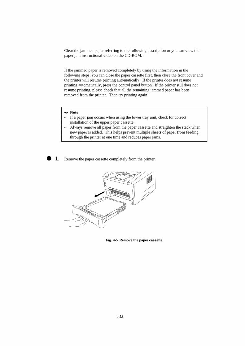
4-12
Clear the jammed paper referring to the following description or you can view thepaper jam instructional video on the CD-ROM.
If the jammed paper is removed completely by using the information in thefollowing steps, you can close the paper cassette first, then close the front cover andthe printer will resume printing automatically. If the printer does not resumeprinting automatically, press the control panel button. If the printer still does notresume printing, please check that all the remaining jammed paper has beenremoved from the printer. Then try printing again.
✒ Note• If a paper jam occurs when using the lower tray unit, check for correct
installation of the upper paper cassette.• Always remove all paper from the paper cassette and straighten the stack when
new paper is added. This helps prevent multiple sheets of paper from feedingthrough the printer at one time and reduces paper jams.
���� 1. Remove the paper cassette completely from the printer.
Fig. 4-5 Remove the paper cassette

CHAPTER 4 TROUBLESHOOTING
4-13
���� 2. Pull any jammed paper up and out of the printer.
Fig. 4-6 Pull the jammed paper up and out
���� 3. Open the front cover.

4-14
���� 4. Remove the drum unit assembly. Pull any jammed paper up and out of the printer.Do not remove the drum unit assembly with additional force at this time if youcannot remove it easily. Instead, pull the edge of the jammed paper from the papercassette.
Fig. 4-7 Remove the drum unit assembly
Fig. 4-8 Pull the jammed paper
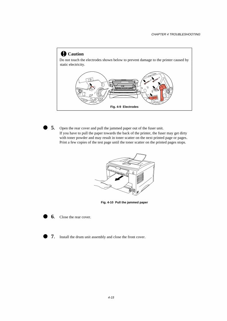
CHAPTER 4 TROUBLESHOOTING
4-15
! CautionDo not touch the electrodes shown below to prevent damage to the printer caused bystatic electricity.
Fig. 4-9 Electrodes
���� 5. Open the rear cover and pull the jammed paper out of the fuser unit.If you have to pull the paper towards the back of the printer, the fuser may get dirtywith toner powder and may result in toner scatter on the next printed page or pages.Print a few copies of the test page until the toner scatter on the printed pages stops.
Fig. 4-10 Pull the jammed paper
���� 6. Close the rear cover.
���� 7. Install the drum unit assembly and close the front cover.
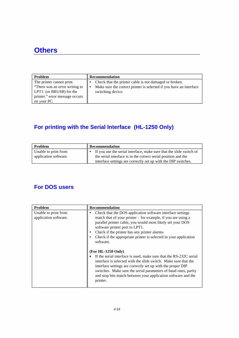
4-16
Others
Problem RecommendationThe printer cannot print.“There was an error writing toLPT1: (or BRUSB) for theprinter.” error message occurson your PC.
• Check that the printer cable is not damaged or broken.• Make sure the correct printer is selected if you have an interface
switching device.
For printing with the Serial Interface (HL-1250 Only)
Problem RecommendationUnable to print fromapplication software.
• If you use the serial interface, make sure that the slide switch ofthe serial interface is in the correct serial position and theinterface settings are correctly set up with the DIP switches.
For DOS users
Problem RecommendationUnable to print fromapplication software.
• Check that the DOS application software interface settingsmatch that of your printer : for example, if you are using aparallel printer cable, you would most likely set your DOSsoftware printer port to LPT1.
• Check if the printer has any printer alarms.• Check if the appropriate printer is selected in your application
software.
(For HL-1250 Only)• • • • If the serial interface is used, make sure that the RS-232C serial
interface is selected with the slide switch. Make sure that theinterface settings are correctly set up with the proper DIPswitches. Make sure the serial parameters of baud rates, parityand stop bits match between your application software and theprinter.

CHAPTER 4 TROUBLESHOOTING
4-17
For Apple Macintosh Computers user
Problem RecommendationUnable to print fromapplication software.
• Make sure that the supplied Macintosh printer driver is installedin the System Folder and it is selected with Chooser.
• Check the PORT selection within the Chooser : it should matchthe port to which you physically attached the printer cable.
• The serial slide switch of the optional interface board should bein the Apple (RS-422A) position.
• Check the printer cable type : you cannot use a Local Talk orstraight-through cable. Refer to Chapter 2 for details on printercable types.
For iMac and Power Macintosh G3 with USB
Problem RecommendationHL-1240 (or HL-1250) doesnot appear in Chooser.
• Check the printer is turned on.• Check the USB interface cable is connected correctly.• Check the printer driver is installed correctly.
Unable to print fromapplication software.
Make sure that the supplied Macintosh printer driver is installed inthe System Folder and it is selected with Chooser.

4-18
Improving the print quality
! CautionIf the Drum LED is on you can clear a print quality problem by replacing the drumunit with a new one. The Drum LED indicates that the drum unit is at the end oflife.
This section provides information on the following topics:
Image defect examples Recommendation
ABCDEFGHabcdefghijk
A B C Da b c d e0 1 2 3 4
DEFefg
Cc d2 3
Faint
• Check the printer's environment. Conditions such as humidity,high temperatures, etc. may cause this print defect to occur.
• If the whole page is too light, toner save mode may be on.Disable toner save mode within the Printer Properties tab of theDriver.
• Try installing a new toner cartridge. See “How to replace theToner cartridge” in Chapter 3.
• Try installing a new drum unit. See "How to replace the Drumunit" in Chapter 3.
ABCDEFGHabcdefghijk
A B C Da b c d e0 1 2 3 4
Gray background
• Make sure that you use paper that meets the Brother’srecommended specifications. See “What kind of paper can Iuse” in Chapter 1.
• Check the printer's environment; high temperature and highhumidity conditions can increase the amount of backgroundshading.
• Installing a new toner cartridge. See "How to replace the Tonercartridge" in Chapter 3.
• Installing a new drum unit. See "How to replace the Drum unit"in Chapter 3.
Ghost
• Make sure that you use paper that meets the specifications. Arough surfaced paper, paper that has absorbed moisture orthick media can cause the problem.
• Make sure that you select the appropriate media type in theprinter driver. See “What kind of paper can I use” in Chapter1.
• Try installing a new drum unit. See “How to replace the Drumunit” in Chapter 3.
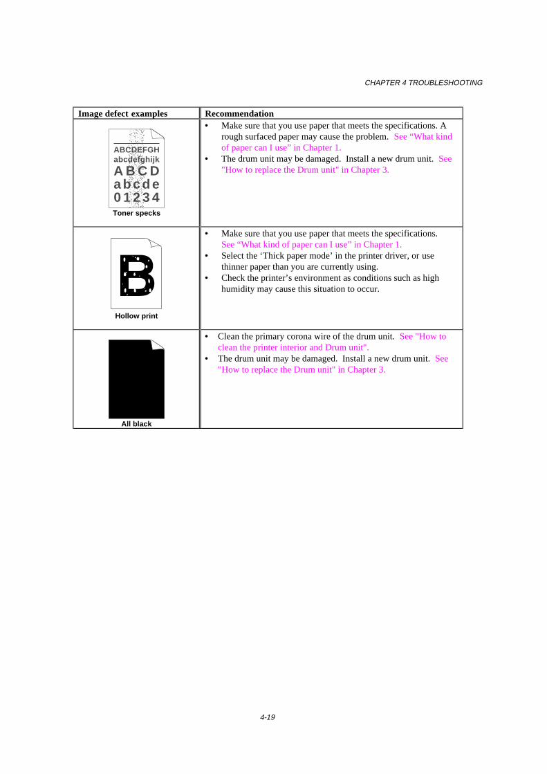
CHAPTER 4 TROUBLESHOOTING
4-19
Image defect examples Recommendation
ABCDEFGHabcdefghijk
A B C Da b c d e0 1 2 3 4Toner specks
• Make sure that you use paper that meets the specifications. Arough surfaced paper may cause the problem. See “What kindof paper can I use” in Chapter 1.
• The drum unit may be damaged. Install a new drum unit. See"How to replace the Drum unit" in Chapter 3.
Hollow print
• Make sure that you use paper that meets the specifications.See “What kind of paper can I use” in Chapter 1.
• Select the ‘Thick paper mode’ in the printer driver, or usethinner paper than you are currently using.
• Check the printer’s environment as conditions such as highhumidity may cause this situation to occur.
All black
• Clean the primary corona wire of the drum unit. See "How toclean the printer interior and Drum unit".
• The drum unit may be damaged. Install a new drum unit. See"How to replace the Drum unit" in Chapter 3.
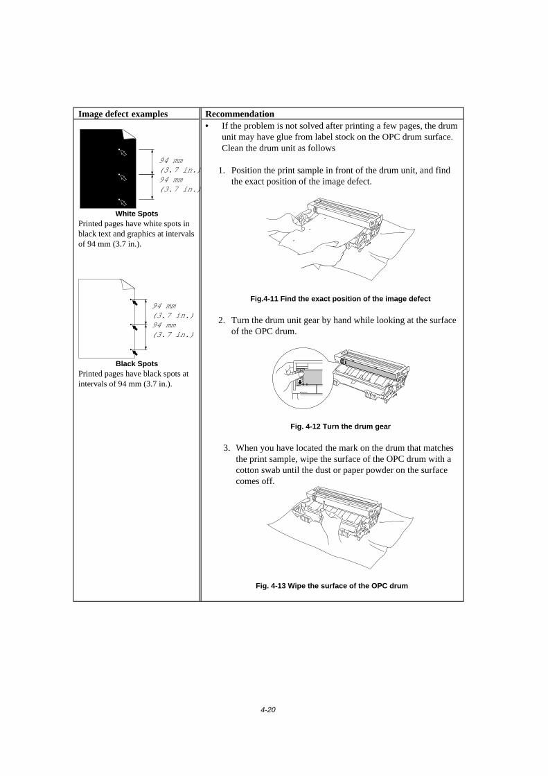
4-20
Image defect examples Recommendation
94 mm(3.7 in.)94 mm(3.7 in.)
White SpotsPrinted pages have white spots inblack text and graphics at intervalsof 94 mm (3.7 in.).
94 mm(3.7 in.)94 mm(3.7 in.)
Black SpotsPrinted pages have black spots atintervals of 94 mm (3.7 in.).
• If the problem is not solved after printing a few pages, the drumunit may have glue from label stock on the OPC drum surface.
Clean the drum unit as follows 1. Position the print sample in front of the drum unit, and find
the exact position of the image defect.
Fig.4-11 Find the exact position of the image defect
2. Turn the drum unit gear by hand while looking at the surfaceof the OPC drum.
Fig. 4-12 Turn the drum gear
3. When you have located the mark on the drum that matchesthe print sample, wipe the surface of the OPC drum with acotton swab until the dust or paper powder on the surfacecomes off.
Fig. 4-13 Wipe the surface of the OPC drum
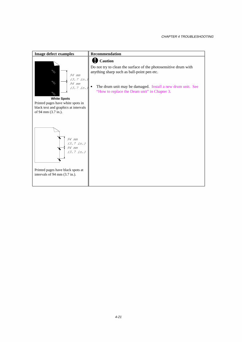
CHAPTER 4 TROUBLESHOOTING
4-21
Image defect examples Recommendation
94 mm(3.7 in.)94 mm(3.7 in.)
White SpotsPrinted pages have white spots inblack text and graphics at intervalsof 94 mm (3.7 in.).
94 mm(3.7 in.)94 mm(3.7 in.)
Printed pages have black spots atintervals of 94 mm (3.7 in.).
! Caution
Do not try to clean the surface of the photosensitive drum withanything sharp such as ball-point pen etc.
• • • • The drum unit may be damaged. Install a new drum unit. See“How to replace the Drum unit” in Chapter 3.
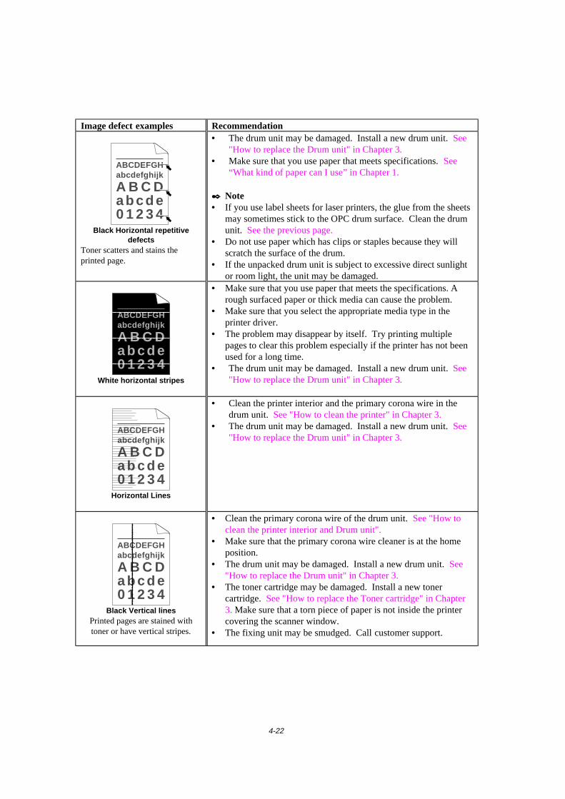
4-22
Image defect examples Recommendation
ABCDEFGHabcdefghijk
A B C Da b c d e0 1 2 3 4
Black Horizontal repetitivedefects
Toner scatters and stains theprinted page.
• The drum unit may be damaged. Install a new drum unit. See"How to replace the Drum unit" in Chapter 3.
• Make sure that you use paper that meets specifications. See“What kind of paper can I use” in Chapter 1.
✒ Note• If you use label sheets for laser printers, the glue from the sheets
may sometimes stick to the OPC drum surface. Clean the drumunit. See the previous page.
• Do not use paper which has clips or staples because they willscratch the surface of the drum.
• If the unpacked drum unit is subject to excessive direct sunlightor room light, the unit may be damaged.
ABCDEFGHabcdefghijk
A B C Da b c d e0 1 2 3 4
White horizontal stripes
• Make sure that you use paper that meets the specifications. Arough surfaced paper or thick media can cause the problem.
• Make sure that you select the appropriate media type in theprinter driver.
• The problem may disappear by itself. Try printing multiplepages to clear this problem especially if the printer has not beenused for a long time.
• The drum unit may be damaged. Install a new drum unit. See"How to replace the Drum unit" in Chapter 3.
ABCDEFGHabcdefghijk
A B C Da b c d e0 1 2 3 4
Horizontal Lines
• Clean the printer interior and the primary corona wire in thedrum unit. See "How to clean the printer" in Chapter 3.
• The drum unit may be damaged. Install a new drum unit. See"How to replace the Drum unit" in Chapter 3.
ABCDEFGHabcdefghijk
A B C Da b c d e0 1 2 3 4
Black Vertical linesPrinted pages are stained withtoner or have vertical stripes.
• Clean the primary corona wire of the drum unit. See "How toclean the printer interior and Drum unit".
• Make sure that the primary corona wire cleaner is at the homeposition.
• The drum unit may be damaged. Install a new drum unit. See"How to replace the Drum unit" in Chapter 3.
• The toner cartridge may be damaged. Install a new tonercartridge. See "How to replace the Toner cartridge" in Chapter3. Make sure that a torn piece of paper is not inside the printercovering the scanner window.
• The fixing unit may be smudged. Call customer support.

CHAPTER 4 TROUBLESHOOTING
4-23
Image defect examples Recommendation.
ABCDEFGHabcdefghijk
A B C Da b c d e0 1 2 3 4
White Vertical streaks
• You may clear the problem by wiping the scanner window witha soft cloth. See “How to clean the printer” in Chapter 3.
• The toner cartridge may be damaged. Install a new tonercartridge. See "How to replace the Toner cartridge" in Chapter3.
ABCDEFGH
abcdefghijk
A B C Da b c d e0 1 2 3 4Page skew
• Make sure the paper or other media is loaded into the papercassette correctly and that the guides are not too tight or tooloose against the paper stack.
• Set the paper guides correctly. Make sure that the tip of thepaper guides fit into the slot correctly. See “How to load paperinto the Paper cassette” in Chapter 2.
• If you are using the manual feed slot see "How to load onesheet of paper manually" in Chapter 1.
• The paper cassette may be too full. See "How to load paperinto the paper cassette" in Chapter 2.
• Check the paper type and quality. See "What kind of paper canI use" in Chapter 1.
Curl or wave
• Check the paper type and quality. Both high temperature andhumidity will cause paper to curl. See “What kind of papercan I use” in Chapter 1.
• If you use the printer infrequently, the paper may have sat fortoo long in the paper cassette. Turn over the stack of paper inthe paper cassette. Also, try rotating the paper 180° in thepaper cassette.
• Try printing using the straight-through output path. See "Howto load one sheet of paper manually" in Chapter 1.
B DEFGHabc efghijk
A C Db c d e1 3 4
Wrinkles or creases
• Make sure that paper is loaded properly. See "How to loadpaper into the paper cassette" in Chapter 1.
• Check the paper type and quality. See “What kind of papercan I use” in Chapter 1.
• Try printing using the straight-through output path. See "Howto load one sheet of paper manually" in Chapter 1.
• Turn over the stack of paper in the tray or try rotating the paper180° in the input tray.
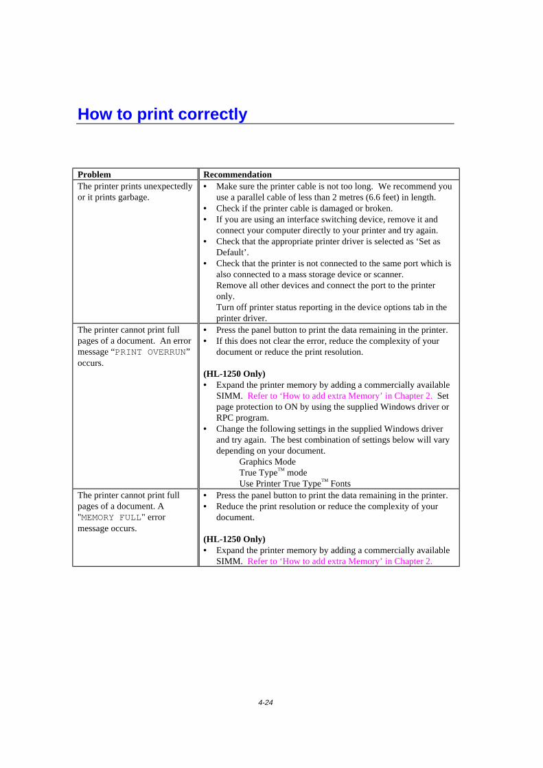
4-24
How to print correctly
Problem RecommendationThe printer prints unexpectedlyor it prints garbage.
• Make sure the printer cable is not too long. We recommend youuse a parallel cable of less than 2 metres (6.6 feet) in length.
• Check if the printer cable is damaged or broken.• If you are using an interface switching device, remove it and
connect your computer directly to your printer and try again.• Check that the appropriate printer driver is selected as ‘Set as
Default’.• Check that the printer is not connected to the same port which is
also connected to a mass storage device or scanner.Remove all other devices and connect the port to the printeronly.Turn off printer status reporting in the device options tab in theprinter driver.
The printer cannot print fullpages of a document. An errormessage “PRINT OVERRUN”occurs.
• Press the panel button to print the data remaining in the printer.• If this does not clear the error, reduce the complexity of your
document or reduce the print resolution.
(HL-1250 Only)• Expand the printer memory by adding a commercially available
SIMM. Refer to ‘How to add extra Memory’ in Chapter 2. Setpage protection to ON by using the supplied Windows driver orRPC program.
• Change the following settings in the supplied Windows driverand try again. The best combination of settings below will varydepending on your document.
Graphics ModeTrue TypeTM modeUse Printer True TypeTM Fonts
The printer cannot print fullpages of a document. A"MEMORY FULL" errormessage occurs.
• Press the panel button to print the data remaining in the printer.• Reduce the print resolution or reduce the complexity of your
document.
(HL-1250 Only)• Expand the printer memory by adding a commercially available
SIMM. Refer to ‘How to add extra Memory’ in Chapter 2.
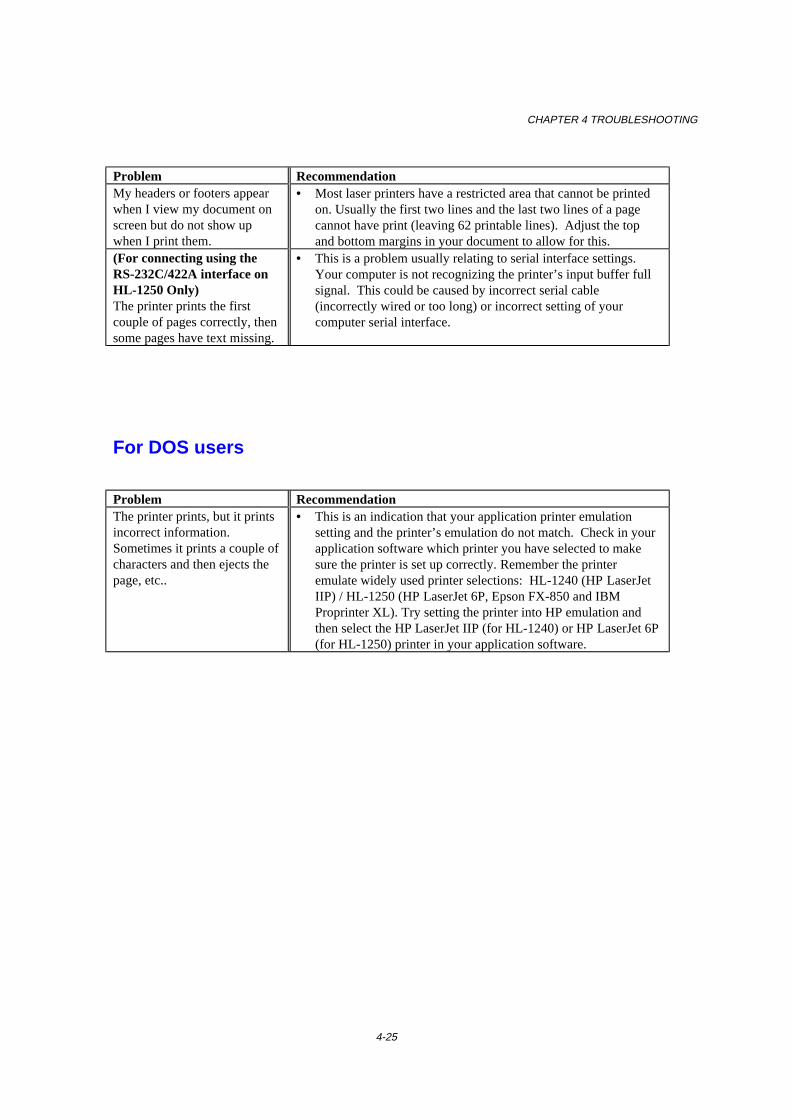
CHAPTER 4 TROUBLESHOOTING
4-25
Problem RecommendationMy headers or footers appearwhen I view my document onscreen but do not show upwhen I print them.
• Most laser printers have a restricted area that cannot be printedon. Usually the first two lines and the last two lines of a pagecannot have print (leaving 62 printable lines). Adjust the topand bottom margins in your document to allow for this.
(For connecting using theRS-232C/422A interface onHL-1250 Only)The printer prints the firstcouple of pages correctly, thensome pages have text missing.
• This is a problem usually relating to serial interface settings.Your computer is not recognizing the printer’s input buffer fullsignal. This could be caused by incorrect serial cable(incorrectly wired or too long) or incorrect setting of yourcomputer serial interface.
For DOS users
Problem RecommendationThe printer prints, but it printsincorrect information.Sometimes it prints a couple ofcharacters and then ejects thepage, etc..
• This is an indication that your application printer emulationsetting and the printer’s emulation do not match. Check in yourapplication software which printer you have selected to makesure the printer is set up correctly. Remember the printeremulate widely used printer selections: HL-1240 (HP LaserJetIIP) / HL-1250 (HP LaserJet 6P, Epson FX-850 and IBMProprinter XL). Try setting the printer into HP emulation andthen select the HP LaserJet IIP (for HL-1240) or HP LaserJet 6P(for HL-1250) printer in your application software.
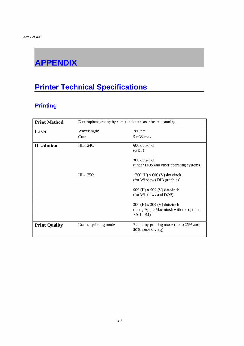
APPENDIX
A-1
APPENDIX
Printer Technical Specifications
Printing
Print Method Electrophotography by semiconductor laser beam scanning
Laser Wavelength: 780 nm
Output: 5 mW max
Resolution HL-1240: 600 dots/inch(GDI )
300 dots/inch(under DOS and other operating systems)
HL-1250: 1200 (H) x 600 (V) dots/inch(for Windows DIB graphics)
600 (H) x 600 (V) dots/inch(for Windows and DOS)
300 (H) x 300 (V) dots/inch(using Apple Macintosh with the optionalRS-100M)
Print Quality Normal printing mode Economy printing mode (up to 25% and50% toner saving)
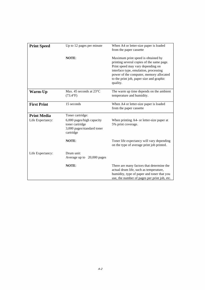
A-2
Print Speed Up to 12 pages per minute When A4 or letter-size paper is loadedfrom the paper cassette
NOTE: Maximum print speed is obtained byprinting several copies of the same page.Print speed may vary depending oninterface type, emulation, processingpower of the computer, memory allocatedto the print job, paper size and graphicquality.
Warm-Up Max. 45 seconds at 23°C(73.4°F)
The warm up time depends on the ambienttemperature and humidity.
First Print 15 seconds When A4 or letter-size paper is loadedfrom the paper cassette
Print Media Toner cartridge:
Life Expectancy: 6,000 pages/high capacitytoner cartridge3,000 pages/standard tonercartridge
When printing A4- or letter-size paper at5% print coverage.
NOTE: Toner life expectancy will vary dependingon the type of average print job printed.
Life Expectancy: Drum unit:Average up to 20,000 pages
NOTE: There are many factors that determine theactual drum life, such as temperature,humidity, type of paper and toner that youuse, the number of pages per print job, etc.
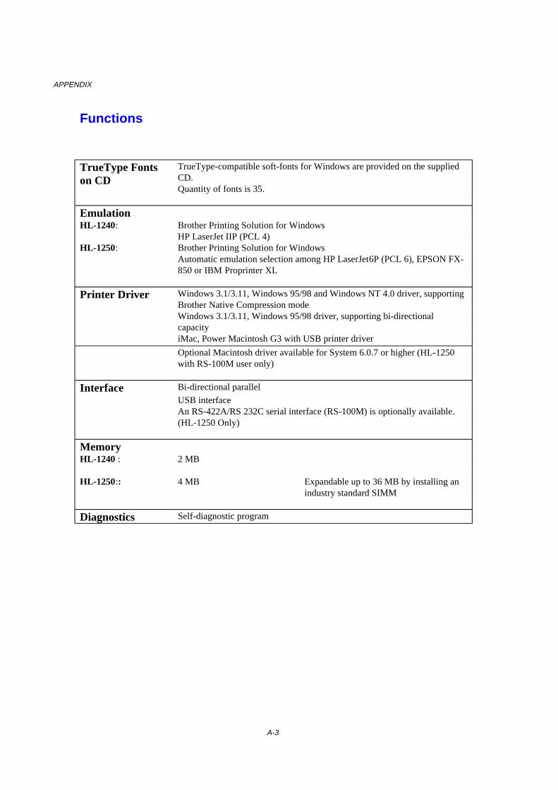
APPENDIX
A-3
Functions
TrueType Fontson CD
TrueType-compatible soft-fonts for Windows are provided on the suppliedCD.Quantity of fonts is 35.
EmulationHL-1240: Brother Printing Solution for Windows
HP LaserJet IIP (PCL 4)HL-1250: Brother Printing Solution for Windows
Automatic emulation selection among HP LaserJet6P (PCL 6), EPSON FX-850 or IBM Proprinter XL
Printer Driver Windows 3.1/3.11, Windows 95/98 and Windows NT 4.0 driver, supportingBrother Native Compression modeWindows 3.1/3.11, Windows 95/98 driver, supporting bi-directionalcapacityiMac, Power Macintosh G3 with USB printer driver
Optional Macintosh driver available for System 6.0.7 or higher (HL-1250with RS-100M user only)
Interface Bi-directional parallel
USB interfaceAn RS-422A/RS 232C serial interface (RS-100M) is optionally available.(HL-1250 Only)
MemoryHL-1240 : 2 MB
HL-1250:: 4 MB Expandable up to 36 MB by installing anindustry standard SIMM
Diagnostics Self-diagnostic program
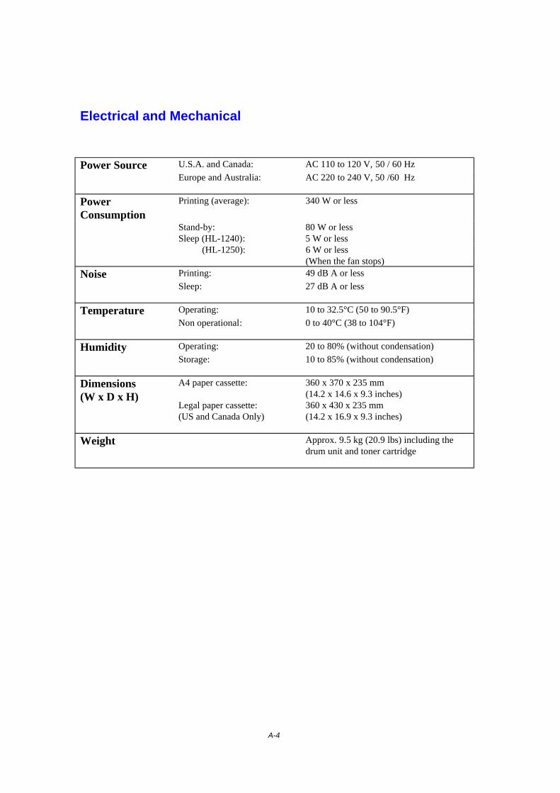
A-4
Electrical and Mechanical
Power Source U.S.A. and Canada: AC 110 to 120 V, 50 / 60 Hz
Europe and Australia: AC 220 to 240 V, 50 /60 Hz
PowerConsumption
Printing (average): 340 W or less
Stand-by: 80 W or lessSleep (HL-1240): 5 W or less (HL-1250): 6 W or less
(When the fan stops)
Noise Printing: 49 dB A or less
Sleep: 27 dB A or less
Temperature Operating: 10 to 32.5°C (50 to 90.5°F)
Non operational: 0 to 40°C (38 to 104°F)
Humidity Operating: 20 to 80% (without condensation)
Storage: 10 to 85% (without condensation)
Dimensions(W x D x H)
A4 paper cassette:
Legal paper cassette:(US and Canada Only)
360 x 370 x 235 mm(14.2 x 14.6 x 9.3 inches)360 x 430 x 235 mm(14.2 x 16.9 x 9.3 inches)
Weight Approx. 9.5 kg (20.9 lbs) including thedrum unit and toner cartridge
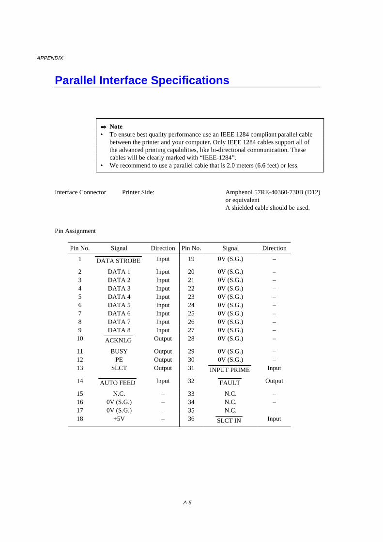
APPENDIX
A-5
Parallel Interface Specifications
✒ Note• To ensure best quality performance use an IEEE 1284 compliant parallel cable
between the printer and your computer. Only IEEE 1284 cables support all ofthe advanced printing capabilities, like bi-directional communication. Thesecables will be clearly marked with “IEEE-1284”.
• We recommend to use a parallel cable that is 2.0 meters (6.6 feet) or less.
Interface Connector Printer Side: Amphenol 57RE-40360-730B (D12)or equivalentA shielded cable should be used.
Pin Assignment
Pin No. Signal Direction Pin No. Signal Direction
1 DATA STROBE Input 19 0V (S.G.) –
2 DATA 1 Input 20 0V (S.G.) –3 DATA 2 Input 21 0V (S.G.) –4 DATA 3 Input 22 0V (S.G.) –5 DATA 4 Input 23 0V (S.G.) –6 DATA 5 Input 24 0V (S.G.) –7 DATA 6 Input 25 0V (S.G.) –8 DATA 7 Input 26 0V (S.G.) –9 DATA 8 Input 27 0V (S.G.) –
10 ACKNLG Output 28 0V (S.G.) –
11 BUSY Output 29 0V (S.G.) –12 PE Output 30 0V (S.G.) –13 SLCT Output 31 INPUT PRIME Input
14 AUTO FEED Input 32 FAULT Output
15 N.C. – 33 N.C. –16 0V (S.G.) – 34 N.C. –17 0V (S.G.) – 35 N.C. –18 +5V – 36 SLCT IN Input
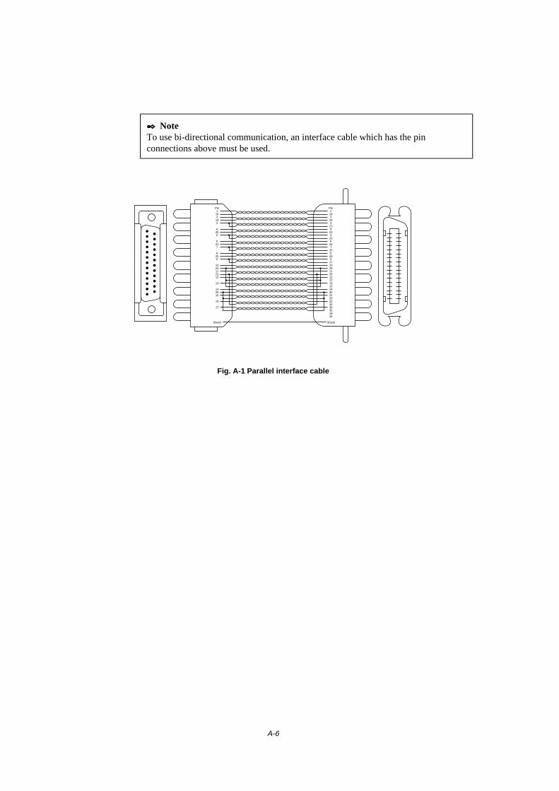
A-6
✒ NoteTo use bi-directional communication, an interface cable which has the pinconnections above must be used.
Pin1182193
4205
6217
8229
1024112312
13
142516
15
17
Shield
Pin1
192
203
214
225
236
247
258
269
27102811291217131514303133323436351816
Shield
Fig. A-1 Parallel interface cable

APPENDIX
A-7
USB (Universal Serial Bus) Interface
Interface connector
4 3
2 1
Fig. A-2 USB interface connector
Pin Assignment
Pin No. Signal1 Vcc (+5V)2 - Data Serial Data -3 + Data Serial Data +4 Ground
A-8
Resident Font
The following bitmapped fonts are resident in this printer.
HL-1240:Bitmapped Fonts
• Brougham 10 (12 point) Normal, Italic, Bold, BoldItalic (Portrait & Landscape)• Brougham 12 (10 point) Normal, Italic, Bold, BoldItalic (Portrait & Landscape)• Letter Gothic 16.66 (8.5 point) Normal, Italic, Bold, BoldItalic (Portrait &
Landscape)
HL-1250 :Bitmapped Fonts
This printer has the following bitmapped fonts. They can be used in theHP LaserJet 6P, EPSON FX-850, and IBM Proprinter XL modes. They have thefollowing characteristics.
• Letter Gothic 16.66 Normal, Italic, Bold, BoldItalic (Portrait & Landscape)• OCR-A(Portrait & Landscape)• OCR-B(Portrait & Landscape)

APPENDIX
A-9
Scalable Fonts
The following scalable fonts can be used in the HP LaserJet 6P,EPSON FX-850 and IBM Proprinter XL modes.
Intellifont Compatible Fonts
• Alaska (Extrabold)• Antique Oakland (Oblique, Bold)• Brougham (Oblique, Bold, BoldOblique)• Cleveland Condensed• Connecticut• Guatemala Antique (Italic, Bold, BoldItalic)• Letter Gothic (Oblique, Bold)• Maryland• Oklahoma (Oblique, Bold, BoldOblique)• PC Tennessee Roman (Italic, Bold, BoldItalic)• PC Brussels Light (Italic, Demi, DemiItalic)• Utah (Oblique, Bold, BoldOblique)• Utah Condensed (Oblique, Bold, BoldOblique)
Microsoft Windows 3.1 TrueType Compatible Fonts
• BR Symbol• Helsinki (Oblique, Bold, BoldOblique)• Tennessee Roman (Italic, Bold, BoldItalic)• W Dingbats
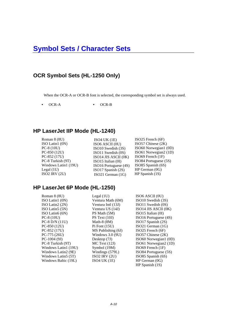
A-10
Symbol Sets / Character Sets
OCR Symbol Sets (HL-1250 Only)
When the OCR-A or OCR-B font is selected, the corresponding symbol set is always used.
• OCR-A • OCR-B
HP LaserJet IIP Mode (HL-1240)Roman 8 (8U)ISO Latin1 (0N)PC-8 (10U)PC-850 (12U)PC-852 (17U)PC-8 Turkish (9T)Windows Latin1 (19U)Legal (1U)ISO2 IRV (2U)
ISO4 UK (1E)ISO6 ASCII (0U)ISO10 Swedish (3S)ISO11 Swedish (0S)ISO14 JIS ASCII (0K)ISO15 Italian (0I)ISO16 Portuguese (4S)ISO17 Spanish (2S)ISO21 German (1G)
ISO25 French (6F)ISO57 Chinese (2K)ISO60 Norwegian1 (0D)ISO61 Norwegian2 (1D)ISO69 French (1F)ISO84 Portuguese (5S)ISO85 Spanish (6S)HP German (0G)HP Spanish (1S)
HP LaserJet 6P Mode (HL-1250)Roman 8 (8U)ISO Latin1 (0N)ISO Latin2 (2N)ISO Latin5 (5N)ISO Latin6 (6N)PC-8 (10U)PC-8 D/N (11U)PC-850 (12U)PC-852 (17U)PC-775 (26U)PC-1004 (9J)PC-8 Turkish (9T)Windows Latin1 (19U)Windows Latin2 (9E)Windows Latin5 (5T)Windows Baltic (19L)
Legal (1U)Ventura Math (6M)Ventura Intl (13J)Ventura US (14J)PS Math (5M)PS Text (10J)Math-8 (8M)Pi Font (15U)MS Publishing (6J)Windows 3.0 (9U)Desktop (7J)MC Text (12J)Symbol (19M)Windings (579L)ISO2 IRV (2U)ISO4 UK (1E)
ISO6 ASCII (0U)ISO10 Swedish (3S)ISO11 Swedish (0S)ISO14 JIS ASCII (0K)ISO15 Italian (0I)ISO16 Portuguese (4S)ISO17 Spanish (2S)ISO21 German (1G)ISO25 French (6F)ISO57 Chinese (2K)ISO60 Norwegian1 (0D)ISO61 Norwegian2 (1D)ISO69 French (1F)ISO84 Portuguese (5S)ISO85 Spanish (6S)HP German (0G)HP Spanish (1S)
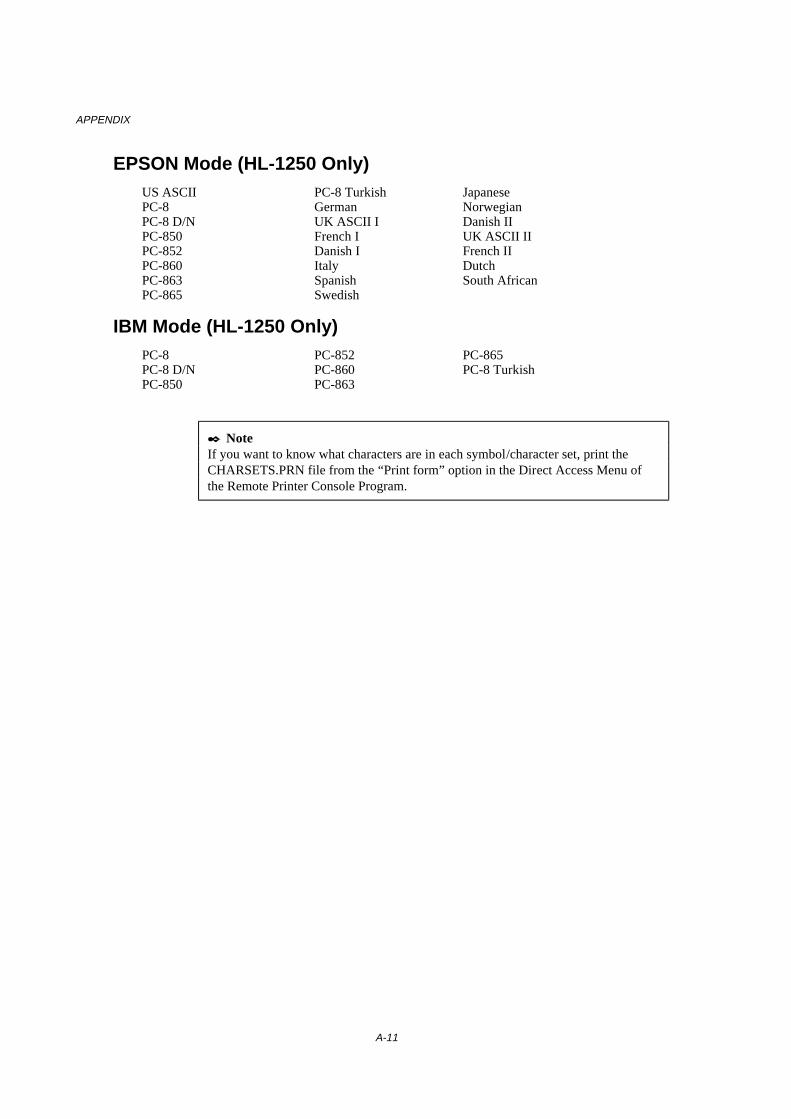
APPENDIX
A-11
EPSON Mode (HL-1250 Only)US ASCIIPC-8PC-8 D/NPC-850PC-852PC-860PC-863PC-865
PC-8 TurkishGermanUK ASCII IFrench IDanish IItalySpanishSwedish
JapaneseNorwegianDanish IIUK ASCII IIFrench IIDutchSouth African
IBM Mode (HL-1250 Only)PC-8PC-8 D/NPC-850
PC-852PC-860PC-863
PC-865PC-8 Turkish
✒ NoteIf you want to know what characters are in each symbol/character set, print theCHARSETS.PRN file from the “Print form” option in the Direct Access Menu ofthe Remote Printer Console Program.
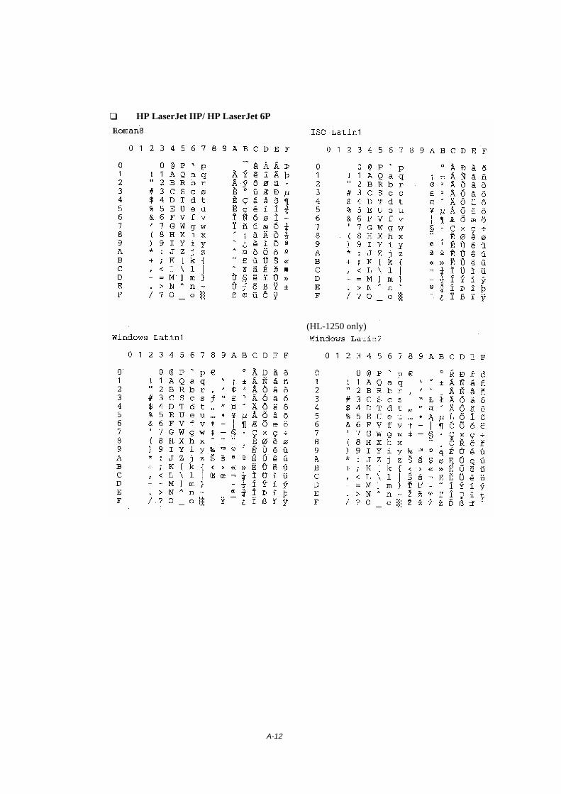
A-12
❏ HP LaserJet IIP/ HP LaserJet 6P
(HL-1250 only)

APPENDIX
A-13
The following table shows characters available only in the corresponding characterset. The numbers at the top of the table are code values with which characters are tobe replaced in the Roman 8 character set. For other characters, see the Roman 8character set.
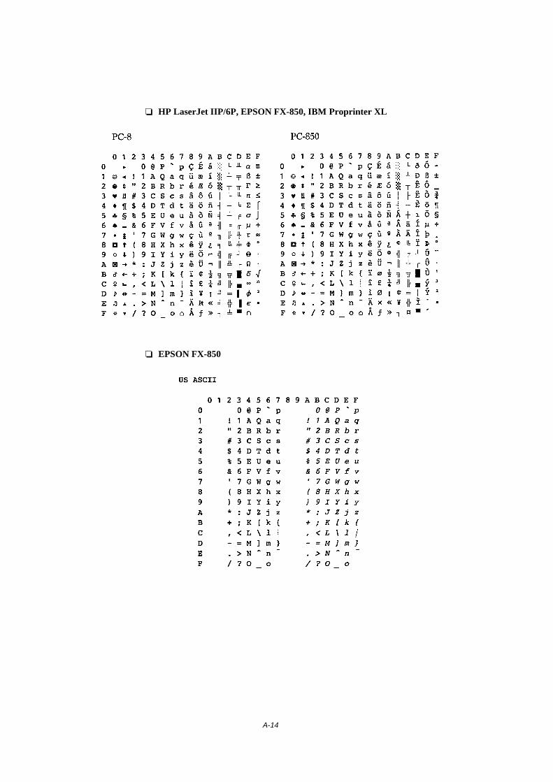
A-14
❏ HP LaserJet IIP/6P, EPSON FX-850, IBM Proprinter XL
❏ EPSON FX-850

APPENDIX
A-15
The following table shows characters available only in the corresponding characterset. The numbers at the top of the table are code values with which characters are tobe replaced in the US ASCII character set. For other characters, see the US ASCIIcharacter set.

A-16
Trademarks
The Brother logo is a registered trademark of Brother Industries, Ltd.
Apple, the Apple Logo, and Macintosh are trademarks, registered in the UnitedStates and other countries, and TrueType is a trademark of Apple Computer, Inc.Epson is a registered trademark and FX-80 and FX-850 are trademarks of SeikoEpson Corporation.Hewlett Packard is a registered trademark and HP LaserJet 6P, 6L, 5P, 5L, 4, 4L 4P,III, IIIP, II, and IIP are trademarks of Hewlett-Packard Company.IBM, IBM PC, and Proprinter are registered trademarks of International BusinessMachines Corporation.Microsoft and MS-DOS are registered trademarks of Microsoft Corporation.Windows is a registered trademark of Microsoft Corporation in the U.S. and othercountries.ENERGY STAR is a U.S. registered mark.
All other brand and product names mentioned in this User’s Guide are registeredtrademarks of their respective companies.
Compilation and Publication Notice
Under the supervision of Brother Industries Ltd., this manual has been compiled andpublished, covering the latest product’s descriptions and specifications.
The contents of this manual and the specifications of this product are subject tochange without notice.
Brother reserves the right to make changes without notice in the specifications andmaterials contained herein and shall not be responsible for any damages (includingconsequential) caused by reliance on the materials presented, including but notlimited to typographical and other errors relating to the publication.
©1999 Brother Industries Ltd.
APPENDIX
A-17
REGULATIONS
Federal Communications Commission(FCC) Declaration of Conformity(For USA Only)
Responsible Party : Brother International Corporation100 Somerset Corporate BoulevardBridgewater, NJ 08807-0911, USATEL : (908) 704-1700
declares, that the productsProduct Name : Brother Laser Printer HL-1240, HL-1250Model Numbers : HL-12Product Options : ALL
complies with Part 15 of the FCC Rules. Operation is subject to the following two conditions:(1) This device may not cause harmful interference, and (2) this device must accept anyinterference received, including interference that may cause undesired operation.
This equipment has been tested and found to comply with the limits for a Class B digitaldevice, pursuant to Part 15 of the FCC Rules. These limits are designed to provide reasonableprotection against harmful interference in a residential installation. This equipment generates,uses, and can radiate radio frequency energy and, if not installed and used in accordance withthe instructions, may cause harmful interference to radio communications. However, there isno guarantee that interference will not occur in a particular installation. If this equipment doescause harmful interference to radio or television reception, which can be determined by turningthe equipment off and on, the user is encouraged to try to correct the interference by one ormore of the following measures:
- Reorient or relocate the receiving antenna.- Increase the separation between the equipment and receiver.- Connect the equipment into an outlet on a circuit different from that to which the receiver is
connected.- Consult the dealer or an experienced radio/TV technician for help.
Important
A shielded interface cable should be used in order to ensure compliance with the limits for aClass B digital device.Changes or modifications not expressly approved by Brother Industries, Ltd. could void theuser’s authority to operate the equipment.
A-18
Industry Canada Compliance Statement (For Canada Only)
This Class B digital apparatus complies with Canadian ICES-003.
Cet appareil numérique de la classe B est conforme à la norme NMB-003 du Canada.
International ENERGY STAR Compliance Statement
The purpose of the International ENERGY STAR Program is to promote the development andpopularization of energy-efficient office equipments, which includes computers, monitors,printers, facsimile receivers and copy machines world-wide.As an International ENERGY STAR partner, Brother Industries, Ltd. has decided that thisproduct meets the guideline of the program.
Radio Interference (220-240 V Model Only)
This printer complies with EN55022(CISPR Publication 22)/Class B.
Before this product is used, ensure that you use a double-shielded interface cable with twisted-pair conductors and that it is marked “IEEE 1284 compliant”. We recommend to use a parallelcable that is 2.0 meters (6.6 feet) or less.
Laser Safety (For 110–120 V Model Only)
This printer is certified as a Class I laser product under the U.S. Department of Health andHuman Services (DHHS) Radiation Performance Standard according to the Radiation Controlfor Health and Safety Act of 1968. This means that the printer does not produce hazardouslaser radiation.
Since radiation emitted inside the printer is completely confined within protective housings andexternal covers, the laser beam cannot escape from the machine during any phase of useroperation.

APPENDIX
A-19
FDA Regulations (For 110-120 V Model Only)
U.S. Food and Drug Administration (FDA) has implemented regulations for laser productsmanufactured on and after August 2, 1976. Compliance is mandatory for products marketed inthe United States. One of the following labels on the back of the printer indicates compliancewith the FDA regulations and must be attached to laser products marketed in the United States.
MANUFACTURED:Brother Corporation (Asia) Ltd. Brother Buji Nan Ling FactoryGold Garden Ind., Nan Ling Village, Buji, Rong Gang, Shenzhen, CHINAThis product complies with FDA radiation performance standards, 21 CFR Subchapter J
MANUFACTURED:BROTHER INDUSTRIES (USA) INC.2950 Brother Blvd., Bartlett, TN 38133, U.S.A.This product complies with FDA radiation performance standards, 21 CFR Subchapter J
MANUFACTURED:BROTHER INDUSTRIES LTD.15-1 Naeshiro-cho Mizuho-ku Nagoya, 467-8561 JapanThis product complies with FDA radiation performance standards, 21 CFR Subchapter J
CautionUse of controls, adjustments or performance of procedures other than those specified in thismanual may result in hazardous radiation exposure.
Declaration of Conformity (For Europe)
We, Brother Industries, Ltd.,15-1, Naeshiro-cho, Mizuho-ku, Nagoya 467-8561, Japan
declare that this product is in conformity with the following normative documents.
Safety: EN 60950, EN 60825EMC: EN 55022 Class B, EN 55024
EN 61000-3-2, EN 61000-3-3following the provisions of the Low Voltage Directive 73/23/EEC and the ElectromagneticCompatibility Directive 89/336/EEC (as amended by 91/263/EEC and 92/31/EEC).
Issued by:Brother Industries, Ltd.Printer Products Division
A-20
IEC 825 Specification (For 220–240 V Model Only)
This printer is a Class 1 laser product as defined in IEC 825 specifications. The label shownbelow is attached in countries where it is required.
CLASS 1LASER PRODUCTAPPAREIL Å LASER DE CLASSE 1LASER KLASSE 1 PRODUKT
This printer has a Class 3B Laser Diode which emits invisible laser radiation in the ScannerUnit. The Scanner Unit should not be opened under any circumstances.
CautionUse of controls, adjustments or performance of procedures other than those specified in thismanual may result in hazardous radiation exposure.
( For Finland and Sweden ) LUOKAN 1 LASERLAITE KLASS 1 LASER APPARAT
Varoitus! Laitteen käyttäminen muulla kuin tässä käyttöohjeessa mainitulla tavalla saattaaaltistaa käyttäjän turvallisuusluokan 1 ylittävälle näkymättömälle lasersäteilylle.
Varning – Om apparaten används på annat sätt än i denna Bruksanvisning specificerats, kananvändaren utsättas för osynlig laserstrålning, som överskrider gränsen för laserklass 1.

APPENDIX
A-21
IMPORTANT - For Your Safety
To ensure safe operation the three-pin electrical plug supplied must be inserted only into astandard three-pin power point which is properly grounded through normal household wiring.
Extension cords used with the equipment must be three-pin plug type and correctly wired toprovide proper grounding. Incorrectly wired extension cords may cause personal injury andequipment damage.
The fact that the equipment operates satisfactorily does not imply that the power is groundedand that the installation is completely safe. For your safety, if in any doubt about the effectivegrounding of the power, consult a qualified electrician.
Disconnect deviceThis printer must be installed near a power outlet which is easily accessible. In case ofemergencies, you must disconnect the power cord from the power outlet in order to shut offpower completely.
Geräuschemission / Acoustic Noise Emission (For Germany Only)
Lpa < 70 dB (A) DIN 45635-19-01-KL2
A-22
IMPORTANT - Wiring Information (For U.K. only)
If the power cord supplied with this printer is not suitable for your electrical outlet, remove theplug from the mains cord and fit an appropriate three pin plug. If the replacement plug isintended to take a fuse then fit a fuse with the same rating as the original.
If a moulded plug is severed from the power cord then it should be destroyed because a plugwith cut wires is dangerous if plugged into a live socket outlet. Do not leave it where a childmight find it.
In the event of replacing the plug fuse, fit a fuse approved by ASTA to BS1362 with the samerating as the original fuse.
Always replace the fuse cover. Never use a plug with the cover omitted.
WARNING - THIS PRINTER MUST BE PROPERLY EARTHED.
The wires in the mains cord are coloured in accordance with the following code:
Green and yellow: GroundBlue: NeutralBrown: Live
The colours of the wiring in the power lead of this printer may not correspond with themarkings which identify the terminals in your plug. If you need to fit a different plug, proceedas follows.
Remove a length of the cord outer sheath, taking care not to damage the coloured insulation ofthe wires inside.
Cut each of the three wires to the appropriate length. If the construction of the plug permits,leave the green and yellow wire longer than the others so that, in the event that the cord ispulled out of the plug, the green and yellow wire will be the last to disconnect.
Remove a short section of the coloured insulation to expose the wires.
The wire which is coloured green and yellow must be connected to the terminal in the plugwhich is marked with the letter “E” or by the earth symbol or coloured green or green andyellow.
The wire which is coloured blue must be connected to the terminal which is marked with theletter “N” or coloured black or blue.
The wire which is coloured brown must be connected to the terminal which is marked with theletter “L” or coloured red or brown.
The outer sheath of the cord must be secured inside the plug. The coloured wires should nothang out of the plug.
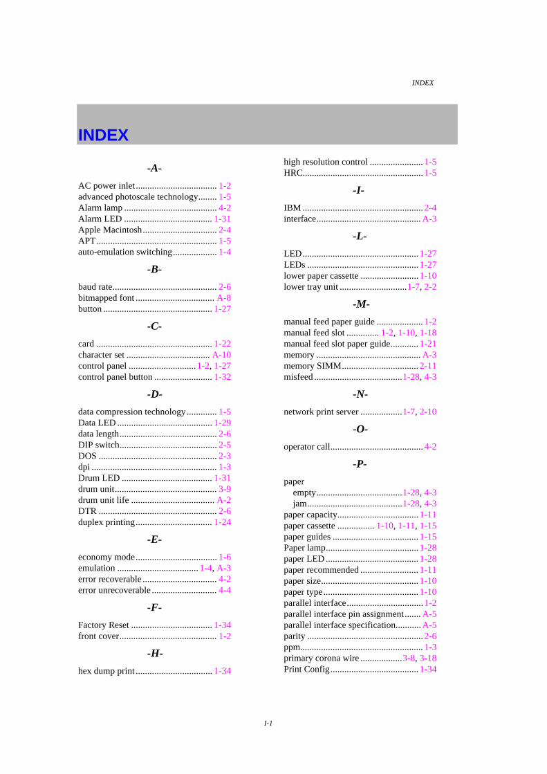
INDEX
I-1
INDEX
-A-
AC power inlet................................... 1-2advanced photoscale technology........ 1-5Alarm lamp ........................................ 4-2Alarm LED ...................................... 1-31Apple Macintosh................................ 2-4APT.................................................... 1-5auto-emulation switching................... 1-4
-B-
baud rate............................................. 2-6bitmapped font .................................. A-8button ............................................... 1-27
-C-
card .................................................. 1-22character set .................................... A-10control panel ............................. 1-2, 1-27control panel button ......................... 1-32
-D-
data compression technology............. 1-5Data LED ......................................... 1-29data length.......................................... 2-6DIP switch.......................................... 2-5DOS ................................................... 2-3dpi ...................................................... 1-3Drum LED ....................................... 1-31drum unit............................................ 3-9drum unit life .................................... A-2DTR ................................................... 2-6duplex printing................................. 1-24
-E-
economy mode................................... 1-6emulation ................................... 1-4, A-3error recoverable ................................ 4-2error unrecoverable ............................ 4-4
-F-
Factory Reset ................................... 1-34front cover.......................................... 1-2
-H-
hex dump print ................................. 1-34
high resolution control ....................... 1-5HRC.................................................... 1-5
-I-
IBM .................................................... 2-4interface............................................. A-3
-L-
LED.................................................. 1-27LEDs ................................................ 1-27lower paper cassette ......................... 1-10lower tray unit .............................1-7, 2-2
-M-
manual feed paper guide .................... 1-2manual feed slot .............. 1-2, 1-10, 1-18manual feed slot paper guide............ 1-21memory ............................................. A-3memory SIMM................................. 2-11misfeed ......................................1-28, 4-3
-N-
network print server ..................1-7, 2-10
-O-
operator call........................................ 4-2
-P-
paperempty.....................................1-28, 4-3jam.........................................1-28, 4-3
paper capacity................................... 1-11paper cassette ................ 1-10, 1-11, 1-15paper guides ..................................... 1-15Paper lamp........................................ 1-28paper LED ........................................ 1-28paper recommended ......................... 1-11paper size.......................................... 1-10paper type......................................... 1-10parallel interface................................. 1-2parallel interface pin assignment....... A-5parallel interface specification........... A-5parity .................................................. 2-6ppm..................................................... 1-3primary corona wire ..................3-8, 3-18Print Config...................................... 1-34
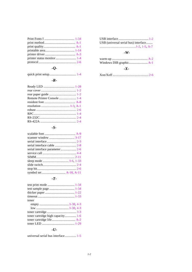
1-2
Print Fonts I ..................................... 1-34print method...................................... A-1print quality....................................... A-1printable area.................................... 1-14printer driver ..................................... A-3printer status monitor ......................... 1-4protocol .............................................. 2-6
-Q-
quick print setup................................. 1-4
-R-
Ready LED ...................................... 1-28rear cover ........................................... 1-2rear paper guide ................................. 1-2Remote Printer Console ..................... 1-4resident font ...................................... A-8resolution ................................... 1-3, A-1robust ................................................. 2-6RPC.................................................... 1-4RS-232C............................................. 2-4RS-422A ............................................ 2-4
-S-
scalable font ...................................... A-9scanner window ............................... 3-17serial interface.................................... 2-3serial interface cable .......................... 2-8serial interface parameter ................... 2-6service call ......................................... 4-4SIMM............................................... 2-11sleep mode ................................ 1-6, 1-33slide switch......................................... 2-4stop bit................................................ 2-6symbol set ............................. A-10, A-11
-T-
test print mode ................................. 1-34test sample page ............................... 1-34thicker paper .................................... 1-22timeout ............................................. 1-33toner
empty .................................... 1-30, 4-3low ........................................ 1-30, 4-3
toner cartridge .................................... 3-3toner cartridge high capacity.............. 1-6toner cartridge life............................. A-2toner LED ........................................ 1-29
-U-
universal serial bus interface.............. 1-5
USB interface ..................................... 1-2USB (universal serial bus) interface........…………………………….1-2, 1-5, A-7
-W-
warm-up ............................................ A-2Windows DIB graphic....................... A-1
-X-
Xon/Xoff ............................................ 2-6


