Page 1
PREFEASIBILITY REPORT
PROPOSED 45 KLPD MOLASSES BASED
DISTILLERY UNIT,
AT
RAVADEWADI, TAl. SHIRUR, DISTRICT PUNE,
MAHARASHTRA STATE
PARAG AGRO FOODS & ALLIED PRODUCTS
PRIVATE LIMITED (PAFAPPL)
Ravadewadi Ta. Shirur, District Pune,
Maharashtra State, 412218
Page 2
Page 1
1.0 Introduction
Parag Agro Foods & Allied Products Private Limited (PAFAPPL) is a private registered
sugar factory located at Ravadewadi Tal. Shirur, District Pune, Maharashtra State. The
factory is duly registered under Companies Act 1956 as Private Limited Company
having Registration No. U15122MH2013PTC244143 dated 07 June, 2013.
The project location is at 4.5 km distance from Ghod River. Water will be lifted from
Kolhapur Type KT Weir at Nimgaon Dude. There is an ample cane potential is in the
command area since very good irrigation facilities are available in Tehsil Khed and
Shirur from Pune district and Parner from Ahmednagar dist. Most of the farmers have
their own lift irrigation facilities.
The existing crushing capacity of sugar unit is 4500 TCD. The project is proposed to be
set up 45 KLPD distillery Unit & 1.5 MW Power unit on slop fired boiler located at
Ravadewadi Ta. Shirur, District Pune, Maharashtra State
1.1 Nature of the Project
Proposed 45 KLPD distillery will be based on molasses as a raw material. The distillery
proposes to achieve zero discharge by implementing multi effect evaporation followed
by spent wash incineration boiler.
1.2 Need of the Project
In order to further improve in financial strength of the mill society by tanking benefit of
the ethanol blending program of the Govt. of India, present demand of Extra Neutral
Alcohol and trend of fast increasing demand for fuel ethanol as well as ENA for potable
liquors, the management of the mill society has decided to set up a distillery for
production of 45 ENA and fuel ethanol as alternate products by utilizing the by-product
of the sugar mill i.e. molasses . The installation of the distillery will not only utilize its by
product for value addition but also generate employment opportunities and ancillary
business opportunities to local people thus will lead to all round development of the
area.
Page 3
Page 2
As the well being of sugar mill is dependent on the full utilization of the by-products
from sugar production, The molasses is one of the most valuable by-product of the
sugar mill is a ready source for the production of alcohol which has many consuming
centers and hence is a valuable product. Hence, the management has rightly chosen to
install a distillery to produce ethyl alcohol from the molasses from the mill.
Page 4
Page 3
2.0 Project Description
2.1 Project Location
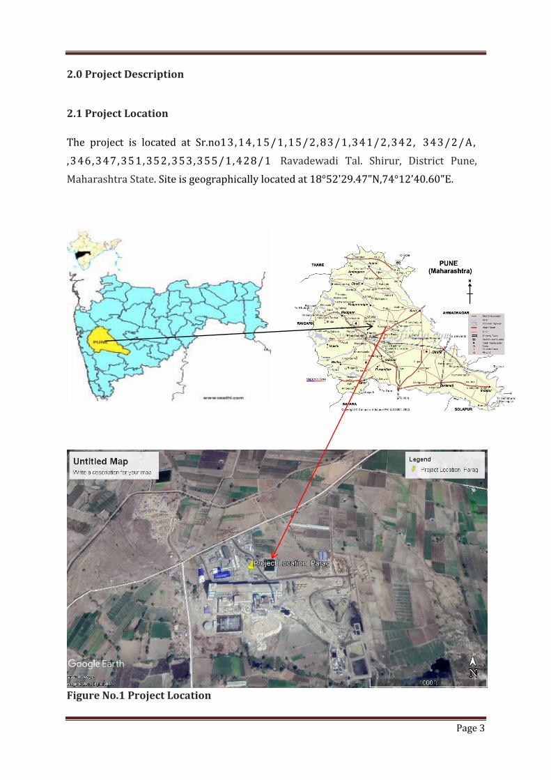
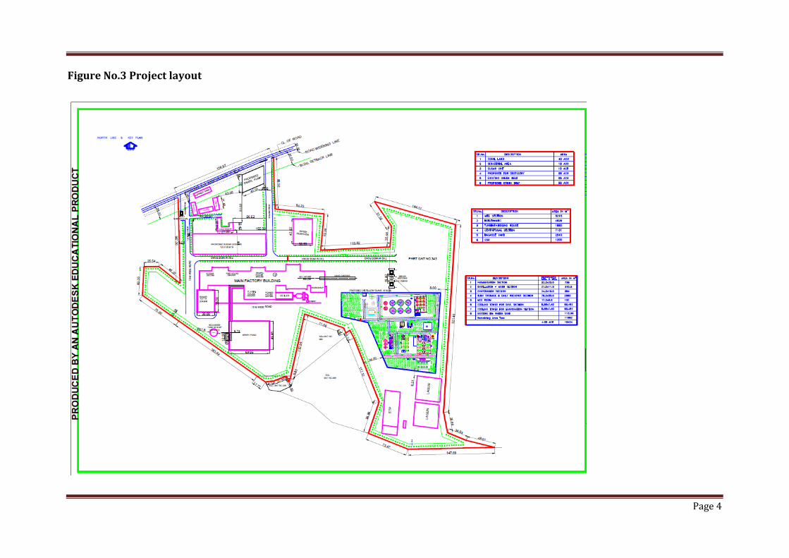
The project is located at Sr.no13, 14, 15/1, 15/2, 83/1,341/2, 342, 343/2/A,
,346, 347,351, 352, 353,355/1, 428/1 Ravadewadi Tal. Shirur, District Pune,
Maharashtra State. Site is geographically located at 18°52'29.47"N,74°12'40.60"E.
Figure No.1 Project Location
Page 5
Page 4
Figure No.3 Project layout
Page 6
Page 5
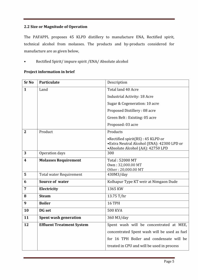
2.2 Size or Magnitude of Operation
The PAFAPPL proposes 45 KLPD distillery to manufacture ENA, Rectified spirit,
technical alcohol from molasses. The products and by-products considered for
manufacture are as given below,
• Rectified Spirit/ impure spirit /ENA/ Absolute alcohol
Project information in brief
Sr No Particulate Description
1 Land Total land 40 Acre
Industrial Activity: 18 Acre
Sugar & Cogeneration: 10 acre
Proposed Distillery : 08 acre
Green Belt : Existing: 05 acre
Proposed: 03 acre
2 Product Products
•Rectified spirit(RS) : 45 KLPD or •Extra Neutral Alcohol (ENA): 42300 LPD or •Absolute Alcohol (AA): 42750 LPD
3 Operation days 300
4 Molasses Requirement Total : 52000 MT Own : 32,000.00 MT Other : 20,000.00 MT
5 Total water Requirement 430M3/day
6 Source of water Kolhapur Type KT weir at Nimgaon Dude
7 Electricity 1365 KW
8 Steam 13.75 T/hr
9 Boiler 16 TPH
10 DG set 500 KVA
11 Spent wash generation 360 M3/day
12 Effluent Treatment System Spent wash will be concentrated at MEE,
concentrated Spent wash will be used as fuel
for 16 TPH Boiler and condensate will be
treated in CPU and will be used in process
Page 7
Page 6
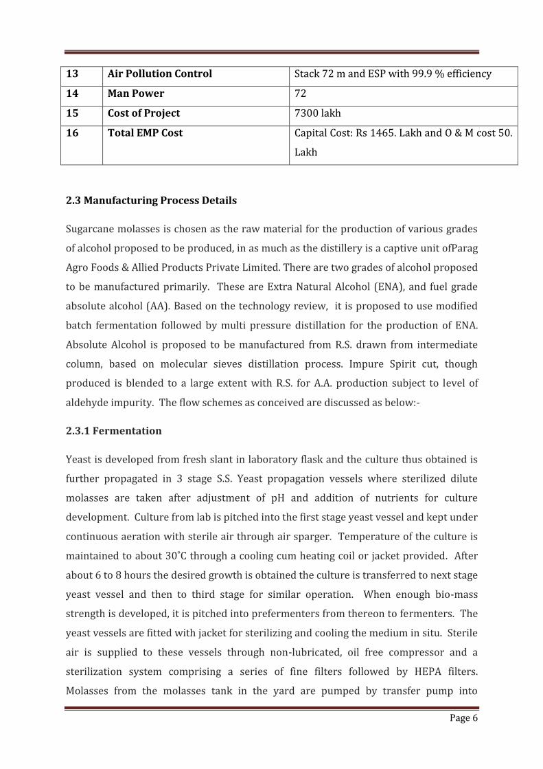
13 Air Pollution Control Stack 72 m and ESP with 99.9 % efficiency
14 Man Power 72
15 Cost of Project 7300 lakh
16 Total EMP Cost Capital Cost: Rs 1465. Lakh and O & M cost 50.
Lakh
2.3 Manufacturing Process Details
Sugarcane molasses is chosen as the raw material for the production of various grades
of alcohol proposed to be produced, in as much as the distillery is a captive unit ofParag
Agro Foods & Allied Products Private Limited. There are two grades of alcohol proposed
to be manufactured primarily. These are Extra Natural Alcohol (ENA), and fuel grade
absolute alcohol (AA). Based on the technology review, it is proposed to use modified
batch fermentation followed by multi pressure distillation for the production of ENA.
Absolute Alcohol is proposed to be manufactured from R.S. drawn from intermediate
column, based on molecular sieves distillation process. Impure Spirit cut, though
produced is blended to a large extent with R.S. for A.A. production subject to level of
aldehyde impurity. The flow schemes as conceived are discussed as below:-
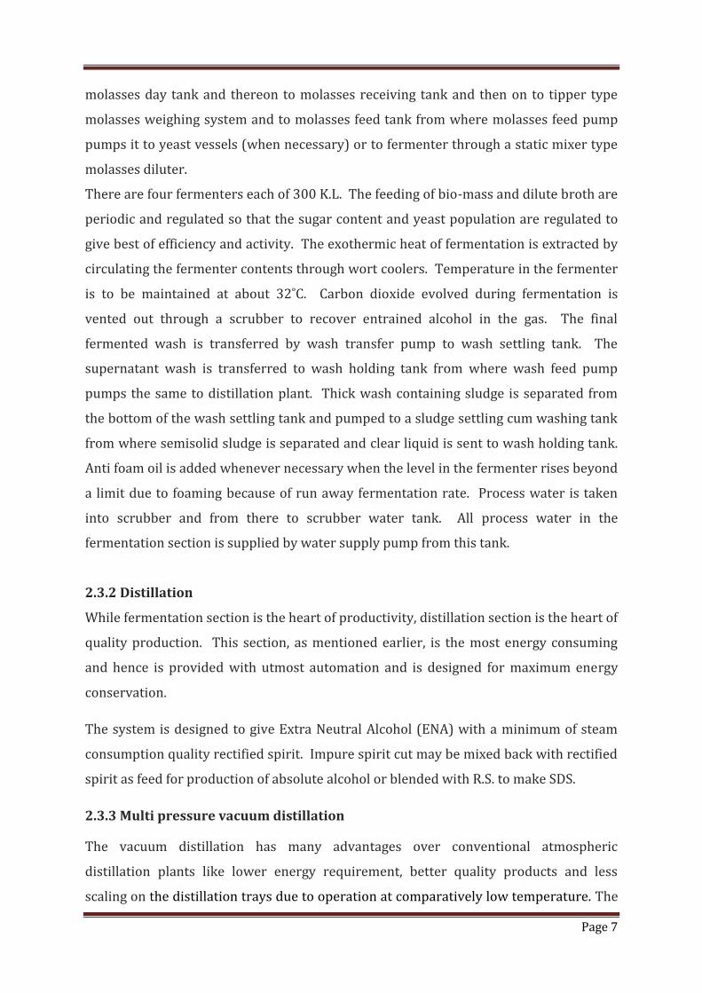
2.3.1 Fermentation
Yeast is developed from fresh slant in laboratory flask and the culture thus obtained is
further propagated in 3 stage S.S. Yeast propagation vessels where sterilized dilute
molasses are taken after adjustment of pH and addition of nutrients for culture
development. Culture from lab is pitched into the first stage yeast vessel and kept under
continuous aeration with sterile air through air sparger. Temperature of the culture is
maintained to about 30˚C through a cooling cum heating coil or jacket provided. After
about 6 to 8 hours the desired growth is obtained the culture is transferred to next stage
yeast vessel and then to third stage for similar operation. When enough bio-mass
strength is developed, it is pitched into prefermenters from thereon to fermenters. The
yeast vessels are fitted with jacket for sterilizing and cooling the medium in situ. Sterile
air is supplied to these vessels through non-lubricated, oil free compressor and a
sterilization system comprising a series of fine filters followed by HEPA filters.
Molasses from the molasses tank in the yard are pumped by transfer pump into
Page 8
Page 7
molasses day tank and thereon to molasses receiving tank and then on to tipper type
molasses weighing system and to molasses feed tank from where molasses feed pump
pumps it to yeast vessels (when necessary) or to fermenter through a static mixer type
molasses diluter.
There are four fermenters each of 300 K.L. The feeding of bio-mass and dilute broth are
periodic and regulated so that the sugar content and yeast population are regulated to
give best of efficiency and activity. The exothermic heat of fermentation is extracted by
circulating the fermenter contents through wort coolers. Temperature in the fermenter
is to be maintained at about 32˚C. Carbon dioxide evolved during fermentation is
vented out through a scrubber to recover entrained alcohol in the gas. The final
fermented wash is transferred by wash transfer pump to wash settling tank. The
supernatant wash is transferred to wash holding tank from where wash feed pump
pumps the same to distillation plant. Thick wash containing sludge is separated from
the bottom of the wash settling tank and pumped to a sludge settling cum washing tank
from where semisolid sludge is separated and clear liquid is sent to wash holding tank.
Anti foam oil is added whenever necessary when the level in the fermenter rises beyond
a limit due to foaming because of run away fermentation rate. Process water is taken
into scrubber and from there to scrubber water tank. All process water in the
fermentation section is supplied by water supply pump from this tank.
2.3.2 Distillation
While fermentation section is the heart of productivity, distillation section is the heart of
quality production. This section, as mentioned earlier, is the most energy consuming
and hence is provided with utmost automation and is designed for maximum energy
conservation.
The system is designed to give Extra Neutral Alcohol (ENA) with a minimum of steam
consumption quality rectified spirit. Impure spirit cut may be mixed back with rectified
spirit as feed for production of absolute alcohol or blended with R.S. to make SDS.
2.3.3 Multi pressure vacuum distillation
The vacuum distillation has many advantages over conventional atmospheric
distillation plants like lower energy requirement, better quality products and less
scaling on the distillation trays due to operation at comparatively low temperature. The
Page 9
Page 8
vacuum distillation produces ethanol of international quality standards and there is a
lot of demand of ethanol from the vacuum distillation process. Alcohol quality, which is
produced from this latest technology, meets to most of the international quality
standards like US, British and Japanese standards.
The multi pressure vacuum distillation approximately requires 50% less steam as
compared to conventional old distillation technologies. The vacuum distillation
consists of distillation columns with high efficiency column trays, condensers, Reboilers,
vacuum pumps and reflux pumps.
In this vacuum distillation, alcohol is separated and concentrated using of fractional
distillation. This is based on difference in boiling points of involved compounds in
mixture. There are eight distillation columns in the system. These are Primary column
and Degasser column, Pre-Rectifier column, Hydro – extractive distillation column,
Rectifier column, Refining column, FOC and De-Aldehyde column.
2.3.4 Primary cum degasser column
Primary column (Analyzer column) is operated under vacuum and it is heated using the
top vapours of the Rectifier column. The vacuum operation of the Primary column
decreases the overall energy requirement of column. Due to vacuum, scaling is also
reduced in this column & plant can be operated for long time smoothly.
The fermented wash is pre-heated using a beer heater and followed by a plate heat
exchanger, then it is fed at the top of Degasser column. The pre heating of mash in two
stages recovers energy and saves steam required for the distillation.
Degasser column separates the impurities on the basis of boiling point. These
impurities are sent to De-aldehyde column.
Alcohol and other volatile compounds are separated from the top of the Primary column
& fed to Pre-Rectifier column.
The liquid waste in fermented wash is reached at the bottom of Primary column. This
liquid waste is called as spent wash & sent to Effluent treatment plant for further
concentration.
Page 10
Page 9
2.3.5 Primary rectifier column
Primary Rectifier column is derived on steam indirectly with the help of one reboiler.
The column gets vapour feed from Analyzer column & bottom of De-aldehyde column.
This column is operated under vacuum. Steam is used as heating medium in its reboiler.
Heavy & light Fusel Oils are separated from this column & fed to De – fusel Oil column,
which is operating at atmospheric pressure.
Impure spirit is also separated from the condenser of this column. Column top vapors
are condensed in one beer heater & remaining in straight condensers.
Alcohol is concentrated in this column & spent water (spent lees) is separated from the
bottom of the column.
Rectified spirit separated from this column is fed to Hydro extraction column.
2.3.6 Hydro extraction column
This column is driven on steam with the help of one reboiler. Rectified spirit which is
separated from Primary Rectifier column is fed to this column. Extraction process takes
place in this column. So, water is added in this column. Impurities which are soluble in
water are taken out from the bottom of this column. Esters in the form of ethyl acetate
are also separated from this column & sent to De-fusel oil column. Bottom stream of
this column is fed to rectifier column.
Top vapors of this column drives the Refining column. Alcohol condensed in the
reboiler of Refining column, sent back return to Hydro column as reflux.
2.3.7 Rectifier column
The bottom product from Hydro Extractive column is transferred to Rectifier column as
feed. The impurities which are not separated in Pre-Rectifier column are separated in
this column.
Steam is given to this column indirectly through reboiler. This column operates under
pressure.Heavy & light fusel oil is separated from this column & sent to De-fusel Oil
column. Top vapors of this column drives Analyzer column. Impure spirit is separated
from this column & fed to De-Aldehydes column.
Page 11
Page 10
The Separated export quality rectified spirit from rectifier is sent to Refining column.
The waste water is separated from Rectifier column is pumped out from bottom of the
column. 70% of spent lee is recycled to hydro column to reduce the water consumption.
2.3.8 Fusel Oil Concentration Column
All fusel oil & esters impurities are fed to this column. Heavy Fusel Oil & Light Fusel Oil
is drawn out from the column & concentrated in decanters. Water is also used for
washing of fusel oil & to recover the alcohol. When fusel oil gets concentrated in
decanter, fusel is oil transferred to fusel oil storage.
2.3.9 Refining column
Relatively high grade R.S. from all tray of this column are made of De-Oxy Copper. The
main purpose of this column is to remove the methanol from Extra Neutral Alcohol.
Technical alcohol is separated from its condenser & sent to storage after cooling.
Extra Neutral Alcohol is collected at the bottom of this column & sent to receiver after
passing it from cooler.
2.3.10 Ethanol production
Absolute alcohol is manufactured by dehydration of Rectified Spirit. The process
adopted here is based on Pressure Swing Adsorption (PSA) system using Molecular
Sieves (3-A). The flow scheme is shown in above referred flow diagram.
Rectified spirit, after preheating by waste hot streams, is vaporized and superheated in
E-03 and E-04 by using medium pressure steam at 3.5 kg /cm3 pressure. The super
heated vapours at temperature of 130° C pass through PSA column S-01A/S-01B where
the water vapors are retained while water free alcohol is released as vapors. The
vapors are condensed in E-07 and E-08 and collected as Absolute Alcohol. When the
molecular sieve bed is saturated with water the alcohol vapors are shifted to the other
tower and the first tower is taken for regeneration. Regeneration is done first by
pressure releasing and creating vacuum and then by elutriating with dehydrated
alcohol vapors from the tower in dehydration operation. The vapors are condensed in
E-06 and E-05 and the vent vapors are recovered through scrubber C-02. The
condensate is fed into column C-01 for re-concentration and vaporization. Vacuum can
be created vacuum by P-04. (Eductor may also be considered for this duty). Product is
Page 12
Page 11
cooled in E-09 and transferred to Absolute Alcohol receiving tank and then on to
storage tank
2.4 Basic Requirement of the project
2.4.1 Raw material
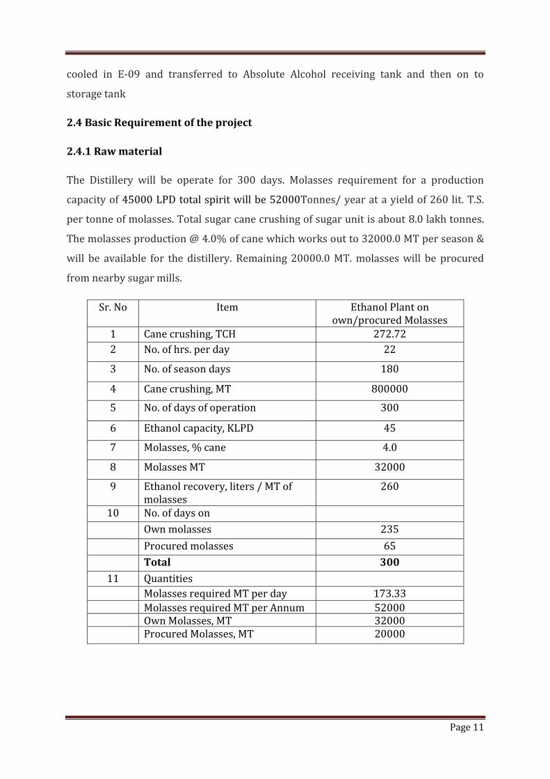
The Distillery will be operate for 300 days. Molasses requirement for a production
capacity of 45000 LPD total spirit will be 52000Tonnes/ year at a yield of 260 lit. T.S.
per tonne of molasses. Total sugar cane crushing of sugar unit is about 8.0 lakh tonnes.
The molasses production @ 4.0% of cane which works out to 32000.0 MT per season &
will be available for the distillery. Remaining 20000.0 MT. molasses will be procured
from nearby sugar mills.
Sr. No Item Ethanol Plant on own/procured Molasses
1 Cane crushing, TCH 272.72
2 No. of hrs. per day 22
3 No. of season days 180
4 Cane crushing, MT 800000
5 No. of days of operation 300
6 Ethanol capacity, KLPD 45
7 Molasses, % cane 4.0
8 Molasses MT 32000
9 Ethanol recovery, liters / MT of molasses
260
10 No. of days on
Own molasses 235
Procured molasses 65
Total 300
11 Quantities
Molasses required MT per day 173.33
Molasses required MT per Annum 52000 Own Molasses, MT 32000 Procured Molasses, MT 20000
Page 13
Page 12
2.4.2 Water Requirement
River water already coming to sugar mill, having a storage capacity about 3,000 m3 will
be pump to distillery as per requirement. The river water is clear however, to remove
any suspended material etc. it will be filtered through a filtration system consisting of
bag filer and ultra filter / pressure filter before use in distillery. Water requirement
comprises of process water in fermentation, cooling water in fermentation, distillation,
power plant and evaporation sections. Soft water is required as make up for cooling
water losses. De-mineralized water is required for use in chemical and bio-chemical
laboratory, ENA production and boiler feed water make up.
Water required in an R.S./ethanol plant comprises of process water in fermentation,
cooling water in Fermentation, distillation, power plant and in evaporation sections
Other requirement is by way of domestic requirement.
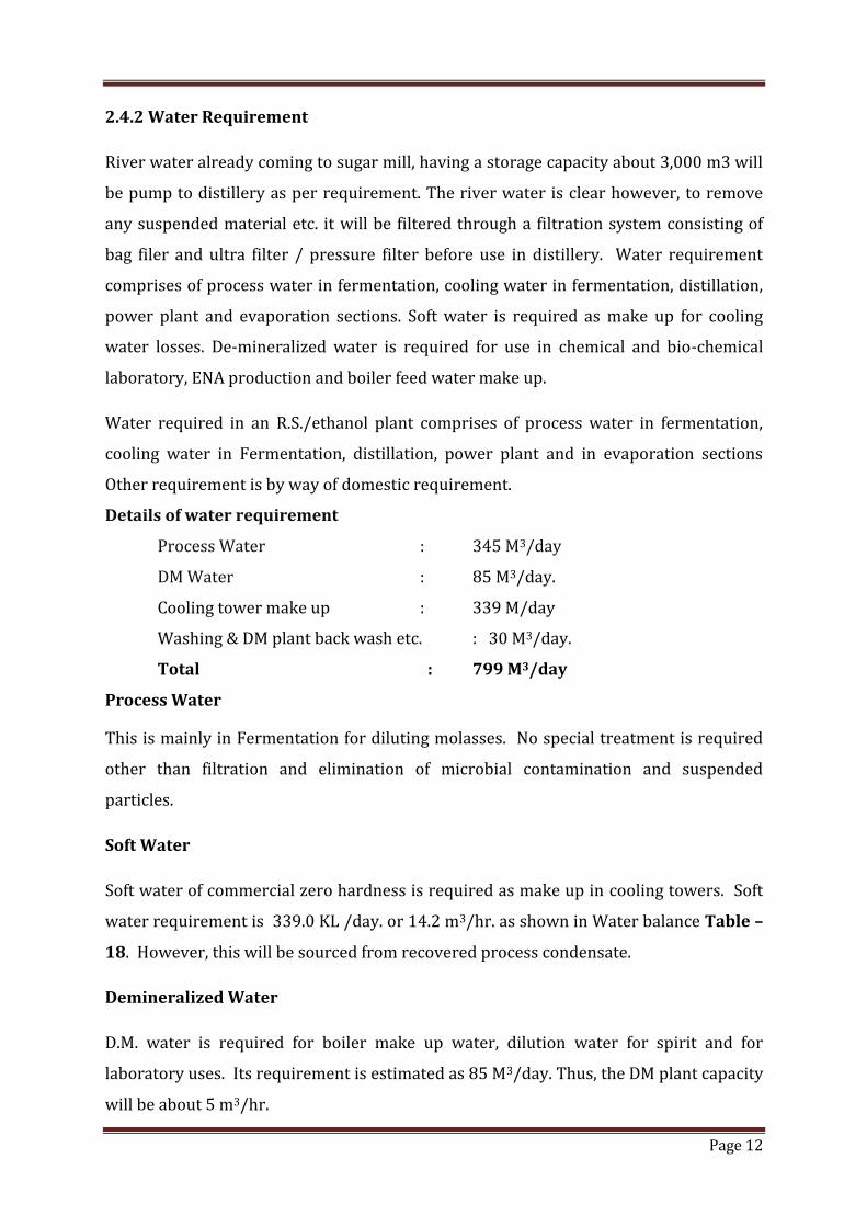
Details of water requirement
Process Water : 345 M3/day
DM Water : 85 M3/day.
Cooling tower make up : 339 M/day
Washing & DM plant back wash etc. : 30 M3/day.
Total : 799 M3/day
Process Water
This is mainly in Fermentation for diluting molasses. No special treatment is required
other than filtration and elimination of microbial contamination and suspended
particles.
Soft Water
Soft water of commercial zero hardness is required as make up in cooling towers. Soft
water requirement is 339.0 KL /day. or 14.2 m3/hr. as shown in Water balance Table –
18. However, this will be sourced from recovered process condensate.
Demineralized Water
D.M. water is required for boiler make up water, dilution water for spirit and for
laboratory uses. Its requirement is estimated as 85 M3/day. Thus, the DM plant capacity
will be about 5 m3/hr.
Page 14
Page 13
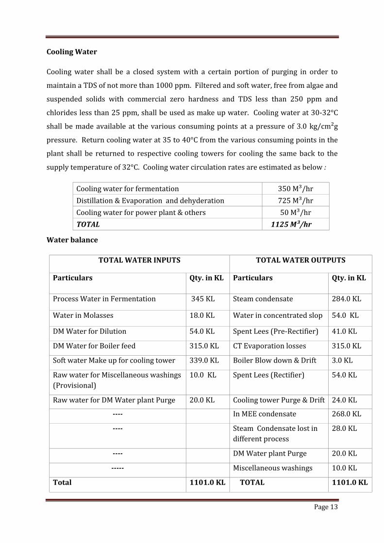
Cooling Water
Cooling water shall be a closed system with a certain portion of purging in order to
maintain a TDS of not more than 1000 ppm. Filtered and soft water, free from algae and
suspended solids with commercial zero hardness and TDS less than 250 ppm and
chlorides less than 25 ppm, shall be used as make up water. Cooling water at 30-32°C
shall be made available at the various consuming points at a pressure of 3.0 kg/cm²g
pressure. Return cooling water at 35 to 40°C from the various consuming points in the
plant shall be returned to respective cooling towers for cooling the same back to the
supply temperature of 32°C. Cooling water circulation rates are estimated as below :
Cooling water for fermentation 350 M³/hr
Distillation & Evaporation and dehyderation 725 M³/hr
Cooling water for power plant & others 50 M³/hr
TOTAL 1125 M³/hr
Water balance
TOTAL WATER INPUTS TOTAL WATER OUTPUTS
Particulars Qty. in KL Particulars Qty. in KL
Process Water in Fermentation 345 KL Steam condensate 284.0 KL
Water in Molasses 18.0 KL Water in concentrated slop 54.0 KL
DM Water for Dilution 54.0 KL Spent Lees (Pre-Rectifier) 41.0 KL
DM Water for Boiler feed 315.0 KL CT Evaporation losses 315.0 KL
Soft water Make up for cooling tower 339.0 KL Boiler Blow down & Drift 3.0 KL
Raw water for Miscellaneous washings
(Provisional)
10.0 KL Spent Lees (Rectifier) 54.0 KL
Raw water for DM Water plant Purge 20.0 KL Cooling tower Purge & Drift 24.0 KL
---- In MEE condensate 268.0 KL
---- Steam Condensate lost in
different process
28.0 KL
---- DM Water plant Purge 20.0 KL
----- Miscellaneous washings 10.0 KL
Total 1101.0 KL TOTAL 1101.0 KL
Page 15
Page 14
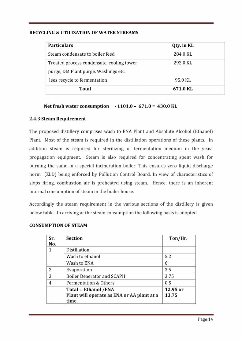
RECYCLING & UTILIZATION OF WATER STREAMS
Particulars Qty. in KL
Steam condensate to boiler feed 284.0 KL
Treated process condensate, cooling tower
purge, DM Plant purge, Washings etc.
292.0 KL
lees recycle to fermentation 95.0 KL
Total 671.0 KL
Net fresh water consumption - 1101.0 – 671.0 = 430.0 KL
2.4.3 Steam Requirement
The proposed distillery comprises wash to ENA Plant and Absolute Alcohol (Ethanol)
Plant. Most of the steam is required in the distillation operations of these plants. In
addition steam is required for sterilizing of fermentation medium in the yeast
propagation equipment. Steam is also required for concentrating spent wash for
burning the same in a special incineration boiler. This ensures zero liquid discharge
norm (ZLD) being enforced by Pollution Control Board. In view of characteristics of
slops firing, combustion air is preheated using steam. Hence, there is an inherent
internal consumption of steam in the boiler house.
Accordingly the steam requirement in the various sections of the distillery is given
below table. In arriving at the steam consumption the following basis is adopted.
CONSUMPTION OF STEAM
Sr. No.
Section Ton/Hr.
1 Distillation
Wash to ethanol 5.2
Wash to ENA 6
2 Evaporation 3.5
3 Boiler Deaerator and SCAPH 3.75
4 Fermentation & Others 0.5
Total : Ethanol /ENA Plant will operate as ENA or AA plant at a time.
12.95 or 13.75
Page 16
Page 15
Steam Generation
Boiler is sized for a MCR capacity of 16.0 T/hr. It is proposed to operate the boiler at a
working pressure of 46.0 ata and steam temperature of 400°C along with facilities for
preheating the water to 140°C by exhaust steam from turbine, at 5.0 ata. The boiler will
operate on concentrated slop with coal as support fuel.
2.4.4 Power Requirement
As the process steam requirement is quite large and suitable for cheap power
generation via cogeneration system a steam turbo –alternator is provided to meet the
process demand of power. A detail of power requirement in the Distillery is given
below:
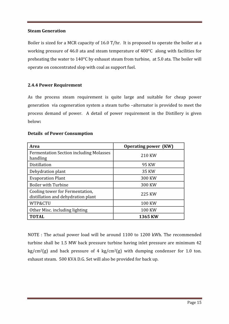
Details of Power Consumption
Area Operating power (KW)
Fermentation Section including Molasses handling
210 KW
Distillation 95 KW
Dehydration plant 35 KW
Evaporation Plant 300 KW
Boiler with Turbine 300 KW
Cooling tower for Fermentation, distillation and dehydration plant
225 KW
WTP&CTU 100 KW
Other Misc. including lighting 100 KW
TOTAL 1365 KW
NOTE : The actual power load will be around 1100 to 1200 kWh. The recommended
turbine shall be 1.5 MW back pressure turbine having inlet pressure are minimum 42
kg/cm2(g) and back pressure of 4 kg/cm2(g) with dumping condenser for 1.0 ton.
exhaust steam. 500 KVA D.G. Set will also be provided for back up.
Page 17
Page 16
3.0 Pollution Control Technology
3.1 Air Pollution
Air pollutants from a distillery are basically from flue gases from boiler. These are
particulates and acidic constituents in the flue coming from fuel. Fuels used are spent
wash and coal.
The coal consumption is 1.44 T/hr and hence the particulate emissions are controlled
through ESP on the flue path prior to going to chimney. The stack height will be 72 M
Ash is collected and sold to brick manufacturers or it can also be sold at potash fertilizer
as it contains high percentage of K2O.
3.2 Waste Water/ Effluent:
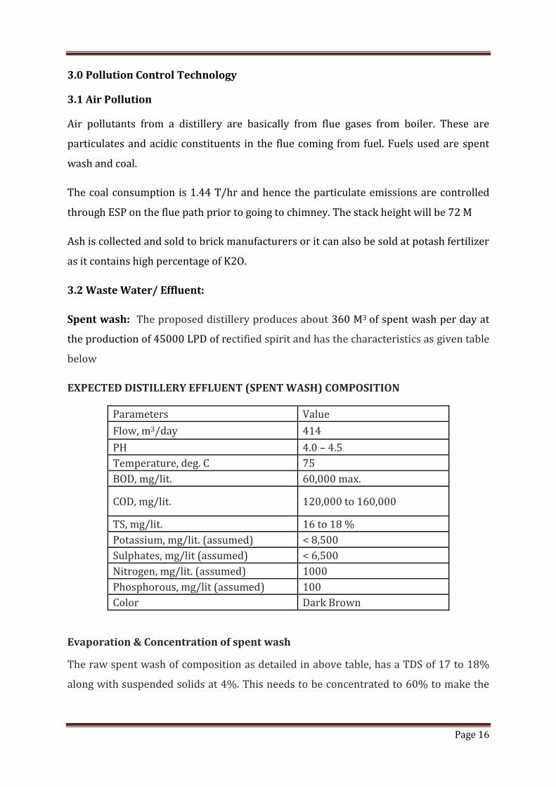
Spent wash: The proposed distillery produces about 360 M3 of spent wash per day at
the production of 45000 LPD of rectified spirit and has the characteristics as given table
below
EXPECTED DISTILLERY EFFLUENT (SPENT WASH) COMPOSITION
Parameters Value
Flow, m3/day 414
PH 4.0 – 4.5
Temperature, deg. C 75
BOD, mg/lit. 60,000 max.
COD, mg/lit. 120,000 to 160,000
TS, mg/lit. 16 to 18 %
Potassium, mg/lit. (assumed) < 8,500
Sulphates, mg/lit (assumed) < 6,500
Nitrogen, mg/lit. (assumed) 1000
Phosphorous, mg/lit (assumed) 100
Color Dark Brown
Evaporation & Concentration of spent wash
The raw spent wash of composition as detailed in above table, has a TDS of 17 to 18%
along with suspended solids at 4%. This needs to be concentrated to 60% to make the
Page 18
Page 17
same suitable for burning. The hot spent wash at about 70 deg. C from analsyser
column is pumped into a storage tank where suspended solids are allowed to settle.
The evaporation is done in a quintuple effect evaporator system. A variety of
combinations of evaporator system can be envisaged. Tentatively a combination of
falling film and forth circulation evaporator is used.
Feed at 70 deg. C taken into 2nd effect, a falling film type evaporator and from thereon it
flows into 3rd to 4th to 5th bodies which are in increasing vacuum. 5th body is forced
circulation rising film type The last body (5th effect) is under 640 to 660 mm vacuum.
Concentrated spent was at about 40% concentration from 5th effect is pumped to first
effect which is a forced circulation evaporator and is at atmospheric pressure and is
supplied with live steam as heating medium. The final product is drawn at 60% solid
concentration from this effect (also called finisher effect). Vapours from each effect
condense in the next effect calandria and finally the last effect vapours at 660 mm.
vacuum go to a surface condenser and the non condensables are drawn out by a
vacuum pump. The vacuum pump also maintains the vacuum in the evaporation
system. The steam condensate from first effect is returned to boiler while the process
condensate from the rest of the effects is collected and treated in the Condensate
Treatment Unit in order to reclaim water and thus effect water conservation
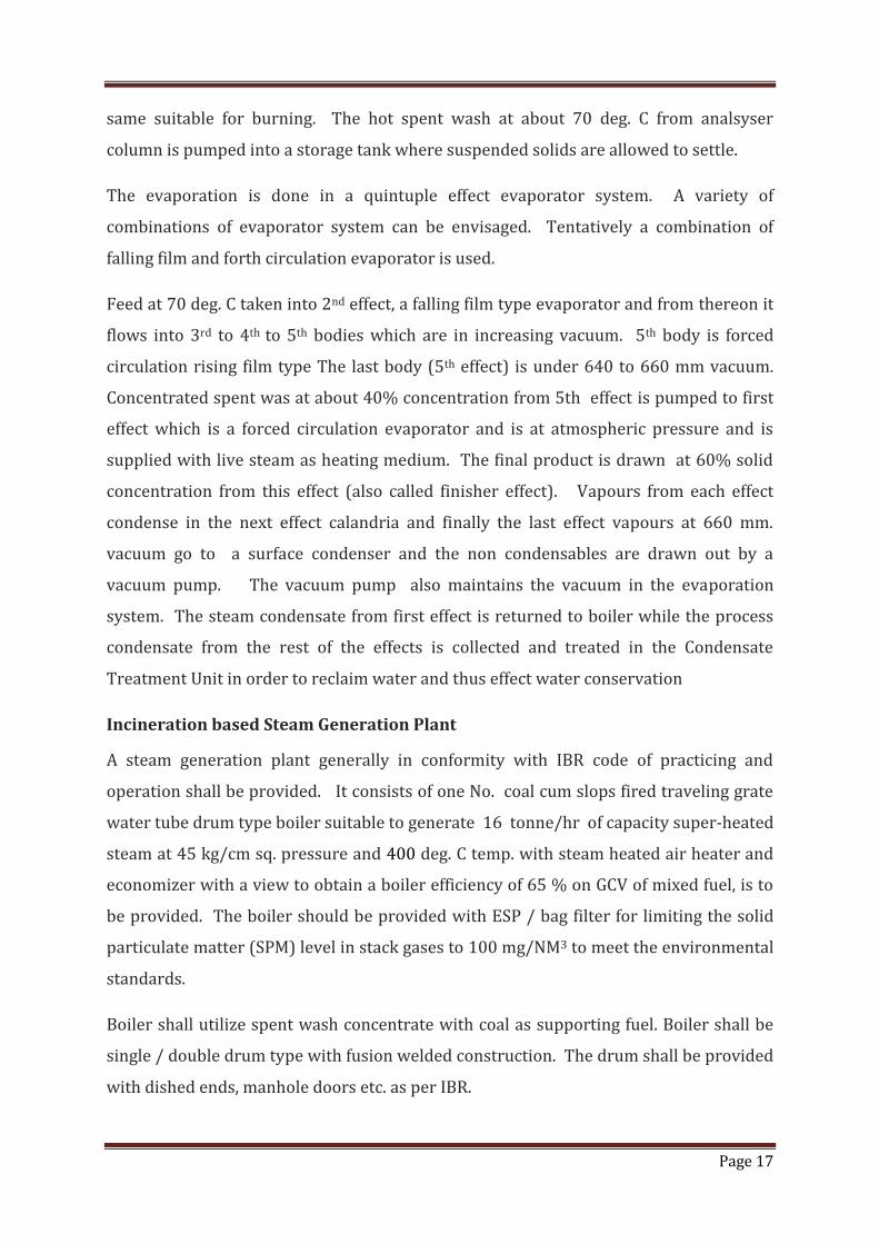
Incineration based Steam Generation Plant
A steam generation plant generally in conformity with IBR code of practicing and
operation shall be provided. It consists of one No. coal cum slops fired traveling grate
water tube drum type boiler suitable to generate 16 tonne/hr of capacity super-heated
steam at 45 kg/cm sq. pressure and 400 deg. C temp. with steam heated air heater and
economizer with a view to obtain a boiler efficiency of 65 % on GCV of mixed fuel, is to
be provided. The boiler should be provided with ESP / bag filter for limiting the solid
particulate matter (SPM) level in stack gases to 100 mg/NM3 to meet the environmental
standards.
Boiler shall utilize spent wash concentrate with coal as supporting fuel. Boiler shall be
single / double drum type with fusion welded construction. The drum shall be provided
with dished ends, manhole doors etc. as per IBR.
Page 19
Page 18
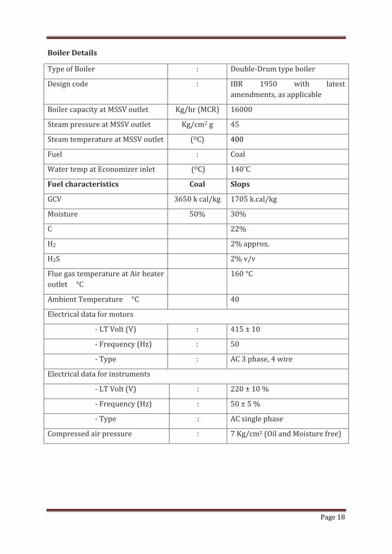
Boiler Details
Type of Boiler : Double-Drum type boiler
Design code : IBR 1950 with latest
amendments, as applicable
Boiler capacity at MSSV outlet Kg/hr (MCR) 16000
Steam pressure at MSSV outlet Kg/cm2 g 45
Steam temperature at MSSV outlet (OC) 400
Fuel : Coal
Water temp at Economizer inlet (OC) 140˚C
Fuel characteristics Coal Slops
GCV 3650 k cal/kg 1705 k.cal/kg
Moisture 50% 30%
C 22%
H2 2% approx.
H2S 2% v/v
Flue gas temperature at Air heater
outlet °C
160 °C
Ambient Temperature °C 40
Electrical data for motors
- LT Volt (V) : 415 ± 10
- Frequency (Hz) : 50
- Type : AC 3 phase, 4 wire
Electrical data for instruments
- LT Volt (V) : 220 ± 10 %
- Frequency (Hz) : 50 ± 5 %
- Type : AC single phase
Compressed air pressure : 7 Kg/cm2 (Oil and Moisture free)
Page 20
Page 19
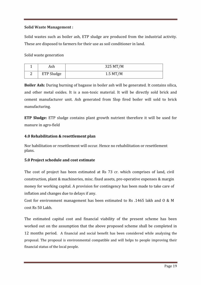
Solid Waste Management :
Solid wastes such as boiler ash, ETP sludge are produced from the industrial activity.
These are disposed to farmers for their use as soil conditioner in land.
Solid waste generation
1 Ash 325 MT/M
2 ETP Sludge 1.5 MT/M
Boiler Ash: During burning of bagasse in boiler ash will be generated. It contains silica,
and other metal oxides. It is a non-toxic material. It will be directly sold brick and
cement manufacturer unit. Ash generated from Slop fired boiler will sold to brick
manufacturing.
ETP Sludge: ETP sludge contains plant growth nutrient therefore it will be used for
manure in agro-field
4.0 Rehabilitation & resettlement plan Nor habilitation or resettlement will occur. Hence no rehabilitation or resettlement plans. 5.0 Project schedule and cost estimate
The cost of project has been estimated at Rs 73 cr. which comprises of land, civil
construction, plant & machineries, misc. fixed assets, pre-operative expenses & margin
money for working capital. A provision for contingency has been made to take care of
inflation and changes due to delays if any.
Cost for environment management has been estimated to Rs .1465 lakh and O & M
cost Rs 50 Lakh.
The estimated capital cost and financial viability of the present scheme has been
worked out on the assumption that the above proposed scheme shall be completed in
12 months period. A financial and social benefit has been considered while analyzing the
proposal. The proposal is environmental compatible and will helps to people improving their
financial status of the local people.