33
Preliminary Characterization Plan for the OU 3-13 Group 6 RD/RA Buried Gas Cylinder Sites: CPP-84 and CPP-94

Preliminary Characterization Plan for the OU 3-13 Group 6 RD/RA Buried Gas Cylinder Sites: CPP-84 and CPP-94

DOEAD-1 0842 (formerly INEEUEXT-2000-00398)
Revision 2
Preliminary Characterization Plan for OU 3-1 3 Group 6 RD/RA Buried Gas Cylinder
Sites: CPP-84 and CPP-94
D. F. Gianotto D. E. Raunig
Published March 2001
Prepared for the U.S. Department of Energy
Idaho Operations Off ice

This Preliminary Characterization Plan outlines the characterization and sampling activities for Waste Area Group 3, Operable Unit 3-13 Group 6 buried gas cylinder sites (CPP-84 and CPP-94) at the Idaho National Engineering and Environmental Laboratory planned for 2000. The investigation supports the Remedial Desigaemedial Action required for WAG 3 by the Federal Facility AgreemenKonsent Order.
This Preliminary Characterization Plan, together with the Quality Assurance Project Plan for Waste Area Groups 1, 2, 3, 4, 5, 6, 7, IO, and lnactive Sites; the Health and Safety Plan for Preliminary Characterization and Post-RD/RA Sampling for WAG 3, OU 3-13, Group 6 Buried Gas Cylinders; and the Hazard Classification for Remediation of OU 3-13 Group 6 RD/RA Buried Gas Cylinder Sites: CPP-84 and CPP-94 constitute the supporting documentation for pre- and post-removal characterization activities at the Group 6 buried gas cylinder sites. This characterization plan (and supporting documentation) provides guidance for sample collection, quality assurance, quality control, analytical procedures, and data management. This characterization plan and the supporting documentation use the ‘Data Quality Objectives’ process to obtain that data are scientifically valid, defensible and of known and acceptable quality.
iii

iv
CONTENTS ... ABSTRACT ...................................................................................................................................... 111
ACRONYMS ..................................................................................................................................... vii
1 .
2 .
3 .
4 .
5 .
INTRODUCTION ...................................................................................................................
1.1 INEEL and WAG 3 Background and Description ........................................................
1.2 Buried Gas Cylinders (CPP-84 and CPP-94) ................................................................
1.2.1 1.2.2 1.2.3 1.2.4
Site Background and Description of CPP-84 ................................................... Contaminants of Potential Concern at CPP-84 ................................................ Site Background and Description of CPP-94 ................................................... Contaminants of Potential Concern at CPP-94 ................................................
DATA QUALITY OBJECTIVES ..........................................................................................
2.1 Pre-Removal Data Collection .......................................................................................
2.2 Post-Removal Data Collection ......................................................................................
SAMPLING DESIGN .............................................................................................................
3.1 Pre-Removal Characterization Activities .....................................................................
3.2 Post-Removal Characterization Activities ....................................................................
Sampling Design for Excavated Areas ............................................................ Sampling Design for Excavated Soils .............................................................
3.2.1 3.2.2 3.2.3 Equipment Reinstate Blanks ............................................................................
SAMPLE EQUIPMENT AND DOCUMENTATION ...........................................................
4.1 Sample Equipment and Supplies ..................................................................................
4.2 Sample Designation ......................................................................................................
Sample Documentation and Management .................................................................... 4.3
SAMPLE HANDLING AND ANALYSIS, WASTE DISPOSAL, AND WASTE MINIMIZATION ....................................................................................................................
5.1 Sample Handling and Analysis .....................................................................................
5.2 Waste Disposal .............................................................................................................
5.2.1 Solid Waste Management ................................................................................ 5.2.2 Soil Specific Waste Management ....................................................................
1-1
1-1
1-4
1-4 1-4 1-4 1-5
2-1
2-1
2-1
3-1
3-1
3-1
3-2 3-3 3-4
4-1
4-1
4-2
4-2
5-1
5-1
5-1
5-1 5-2
V
BBWI
CERCLA
CFA
CLP
COC
COPCS
CPP
cv D&D
DAR
DOE
DOE-ID
DQO
EPA
ER
ERIS
FFNCO
FSP
FTL
GPS
HASP
HF
ICPP
IDEQ
IDHW
IDW
Bechtel BWXT Idaho, LLC
Comprehensive Environmental Response, Compensation, and Liability Act
Central Facilities Area
Contract Laboratory Program
chain of custody
contaminants of potential concern
Chemical Processing Plant (building designator at INTEC)
coefficient of variation
deactivation and decommissioning
document action request
U.S. Department of Energy
U.S. Department of Energy, Idaho Operations Office
data quality objective
U.S. Environmental Protection Agency
environmental restoration
Environmental Restoration Information System
Federal Facility AgreementIConsent Order
field sampling plan
field team leader
Global Positioning System
health and safety plan
hydrofluoric
Idaho Chemical Processing Plant (former name of INTEC)
Idaho Department of Environmental Quality
Idaho Department of Health and Welfare
investigation-derived waste
vii

IEDMS
INEEL
INEL
INTEC
MCP
MDL
ou PPE
PRG
QA
QNQC
QAPjP
RBC
RD/RA
RI/FS
ROD
SAP
SMO
SOP
svoc TAL
TPR
TRA
voc WAG
WGS
Integrated Environmental Data Management System
Idaho National Engineering and Environmental Laboratory (formerly called INEL)
Idaho National Engineering Laboratory (former name of the INEEL)
Idaho Nuclear Technology Engineering Center
management control procedure
method detection limit
operable unit
personal protective equipment
preliminary remediation goal
quality assurance
quality assurance/quality control
quality assurance project plan
risk based concentration
remedial designhemedial investigation
remedial investigatiordfeasibility study
Record of Decision
sampling and analysis plan
Sample Management Office
standard operating procedure
semivolatile organic compound
target analyte list
technical procedure
Test Reactor Area
volatile organic compound
waste area group
Waste Generator Services
viii

Preliminary Characterization Plan for OU 3-13 Group 6 RD/RA Buried Gas Cylinder Sites: CPP-84 and CPP-94
1. INTRODUCTION
This Characterization Plan provides guidance for site characterization and sampling activities at two Waste Area Group (WAG) 3, Group 6 sites (Chemical Processing Plant [CPPI-84 and CPP-94). In accordance with the Federal Facility Agreement and Consent Order (FFNCO) (DOE-ID 1991), these data are needed for the remedial designhemedial action (RD/RA) for Operable Unit (OU) 3-13 at the Idaho National Engineering and Environmental Laboratory (INEEL). This Characterization Plan is written in accordance with the FFAKO Action Plan and the INEEL Environmental Restoration (ER) Management Control Procedure (MCP)-24 1, “Preparation of Characterization Plans.” This plan is implemented with the Quality Assurance Project Plan for Waste Area Groups I , 2, 3, 4, 5, 6, 7, IO, and Inactive Sites (DOE-ID 1997); the Health and Safety Plan for Preliminary Characterization and Post-RDLRA Sampling for WAG 3, OU 3-13, Group 6 Buried Gas Cylinders (INEEL 2000a); the Hazard Classification for Remediation of OU 3-13 Group 6 RD/RA Buried Gas Cylinder Sites: CPP-84 and CPP-94, (INEEL 2000b); and the OU 3-13 RDLRA Scope of Work (DOE-ID 2000).
This plan outlines the characterization and sampling activities at CPP-84 and CPP-94 prior to removal actions (pre-removal characterization) and at the completion of removal actions (post-removal characterization). The activities and procedures for the removal and treatment of the buried gas cylinders are not covered under this characterization plan, but will be covered under a separate work plan.
1.1 INEEL and WAG 3 Background and Description
The INEEL is located in southeastern Idaho and occupies 2,305 km’ (890 mi’) of the northwestern portion of the Eastern Snake River Plain (Figure 1-1). WAG 3 is comprised of the sites at Idaho Nuclear Technology Engineering Center (INTEC). Remedial ZnvestigatiodFeasibiZity Study (RVFS) of Operable Unit (OU) 3-13 represents a comprehensive evaluation of previously identified sites at INTEC. OU 3-13 is divided into seven groups based on similar contaminant types, accessibility, or geographic proximity. Group 6 consists of site CPP-84 and CPP-94; these two sites are located near INTEC as shown Figure 1-2.
1-1

+ ' ? '
n . . . . ... . .. . . .. .
FIgure 1-1, Map of the INEEL showing the location of INTEC.
1-2

1-. t
1-3

1.2 Buried Gas Cylinders (CPP-84 and CPP-94)
1.2.1 Site Background and Description of CPP-84
CPP-84 was identified and added to the FFA/CO as a new site in 1994. The site is located between INTEC and Lincoln Boulevard and about 18 m (60 ft) south of the Big Lost River (Figure 1-2). The site consists of a buried trench where compressed gas cylinders were disposed of after initial construction of INTEC (previously known as the Idaho Chemical Processing Plant or ICPP) in 1952.
A preliminary survey was conducted by INTEC Quality Assessment personnel using ground-penetrating radar to estimate the horizontal and vertical extent of the trench. The trench is currently staked and measures approximately 6 x 9 m (20 x 30 ft) and approximately 2 m (5 ft) deep. The cylinders originated from maintenance buildings and contained gases used for construction purposes. Available information indicates that the types of gases would be limited to acetylene, compressed air, argon, carbon dioxide, helium, nitrogen, and oxygen. It is estimated there are between 40 and 100 gas cylinders buried at this location. It is not known for certain whether the cylinders were buried because they were empty, partially empty, leftoverhnused, or damaged.
The primary hazard posed at CPP-84 is an acute physical hazard posed by the presence of gas cylinders that may be pressurized. However, if the cylinders are over pressurized and are ruptured, the cylinders could create a projectile hazard to personnel. The acetylene gas is considered a simple asphyxiant and may also present a flammable hazard if punctured and ignited.
1.2.2 Contaminants of Potential Concern at CPP-84
The contaminants of potential concern (COPCs) at CPP-84 (after cylinder removal) are
0 Acetone and asbestos. Both may have been used as fillers and stabilizers in acetylene cylinders. If acetylene tanks are present and if they have been ruptured, it is likely any acetone filler would have already vaporized. Similarly, asbestos (if present in an acetylene cylinder) is in a bound and non-friable state and would only pose a soil hazard if the cylinder were ruptured.
Arsenic, barium, beryllium, cadmium, chromium, cobalt, copper, iron, lead, mercury, and nickel. The inorganics may be present in carbon steel or the stainless steel makeup of the cylinders or in the paints used on the cylinders. There is a potential that the inorganics may leach into the soil from corrosion, oxidation (rusting), and cylinder deterioration.
1.2.3 Site Background and Description of CPP-94
CPP-94 was identified and added to the FFA/CO as a new site in 1997. CPP-94 is located about 2.4 km (1.5 mi) northeast of INTEC along an unpaved security road (Figure 1-2). The main area of the site contains one fully exposed cylinder and four buried cylinders. One additional buried cylinder is located approximately 12 m (40 ft) to the northeast. It is believed that the cylinders were placed at their current location sometime in the 1950s. A review of the existing documentation does not reveal the source of the cylinders.
During the initial inspection of CPP-94, vegetation in the immediate area appeared stressed and four small aluminum tags stamped “Hydrofluoric Acid” were found near the cylinders. Hydrofluoric (HF) acid (a solution of HF gas in water) is used as a major component in the spent fuel dissolution process and is a listed hazardous waste when disposed. It is therefore assumed that the cylinders may
1-4

contain either HF acid or HF gas. Rope barriers and danger signs have been placed around the site to control access.
Anhydrous J3F is a colorless, poisonous gas that is extremely reactive and highly corrosive to skin, eyes, lungs and mucous membranes, causing severe bums. If the cylinders contain HF and are under pressure and ruptured, the HF presents significant inhalation, skin, and eye hazards. In addition, an over pressurized cylinder poses an acute safety hazard as a projectile or from fragmentation. If an HF cylinder has already been ruptured, the HF would have likely been consumed by the surrounding soil and been mineralized into fluoride salts.
1.2.4 Contaminants of Potential Concern at CPP-94
The COWS at CPP-94 (after cylinder removal) are
Fluoride. Fluoride salts are the primary residual breakdown products from HF in soil. It is a potential health and ecological hazard at elevated concentrations.
Arsenic, barium, beryllium, cadmium, chromium, cobalt, copper, iron, lead, mercury, and nickel. The inorganics may be present in carbon steel or the stainless steel makeup of the cylinders or in the paints used on the cylinders. There is a potential that the inorganics m a y leach into the soil from corrosion, oxidation (rusting), and cylinder deterioration.
1-5
2. DATA QUALITY OBJECTIVES
The data collection objectives are discussed in the context of the data quality objectives (DQOs) process, as defined by Guidancefor the Data QuaZity Objectives Process (EPA 1994b), discussed in the QAPjP (DOEAD-10587) and mandated for use in accordance with MCP-227, “Sampling and Analysis Process for CERCLA and D&D Activities.” The DQO process was developed by the EPA to ensure that the type, quantity, and quality of data used in decision making are appropriate for the intended application. The DQO process includes seven steps, each of which has specific outputs:
1.
2.
3.
4.
5 .
6.
7.
State the problem. Concisely describe the problem to be studied. Review prior studies and existing information to gain an acceptable understanding of the problem.
Identify the decision. Using new data, identify the decision that will solve the problem.
Identify the inputs tu the decision. Identify the jnformation that needs to be learned and the measurements to be taken in order to resolve the decision.
Define the study boundaries. Specify the conditions (time periods and situations) to which decisions will apply and within which the data should be collected.
Develop a decision rule. Integrate the outputs from previous steps into an “if.. .then” statement that defines the conditions that would cause the decision-maker to choose among alternative actions.
Specib acceptable limits on decision errors. Define the decision-maker’s acceptable decision error rates based on a consideration of the consequences of making an incorrect decision. A decision error rate is the probability of making an incorrect decision based on data that inaccurately estimate the true state of nature (EPA 1994).
Optimize the design. Evaluate information from the previous steps and generate alternative sampling designs. Choose the most resource-efficient design that meets all DQOs.
2.1 Pre-Removal Data Collection
Geophysical data will be collected at CPP-84 and CPP-94 before cylinder removal is conducted. The purpose of this data collection effort is to better characterize the spatial distribution and extent of the buried cylinders prior to removal activities. Portable isotopic neutron spectroscopy (PINS) will be used at CPP-94 to determine the presence of HF in the fully exposed cylinder. The PINS data will be used to support decisions for planning removal activities. A radiological survey and soil pH assessment will also be performed for health and safety screening. Refer to Table 2-1 for details of the DQO process for pre- removal data collection.
2.2 Post-Removal Data Collection
Soil data will be collected at CPP-84 and CPP-94 at the conclusion of cylinder removal activities. The purpose of this data collection effort is to characterize soil at the excavation bottom and, if visual evidence is present, characterize the soil removed from the excavation (the spoil pile). Soil samples will be collected and analyzed for COPCs at an off-site laboratory. A confirmatory geophysical survey will also be conducted after removal to serve as confirmation that all cylinders have been removed. Refer to Table 2-2 for details of the DQO process for post-removal data collection.
2- I

Table 2-1. Pre-removal data qualitv obiectives for OU 3- 13 Group 'CPP-84 and CPP-94). Step 1.
Problem Statement State the problem Insufficient data exists at sites CPP-84 and CPP-94 to adequately define the spatial extent of the buried gas cylinders. A more thorough characterization into the surface and subsurface distribution of buried cylinders is needed to guide and direct excavation and removal activities.
Note: The intent cgthis dutu cvllection is to provide qiiulitutive infirmution und guidunce tv ,siippvrt removal uctivities.
Step 2. Decision Statement
ldentifi the principal study question (PSe) What is the spatial distribution and extent of the buried gas cylinders?
Alternative actions resulting from resolution of the PSQ Alt I: The distribution and extent of the buried gas cylinders will be better characterized.
m: The distribution and extent of the buried gas cylinders will not be better c haracterized.
Make Decision Statement Determine whether or not the distribution and extent of the buried gas cylinders has been adequately addressed.
Step 3. Decision Inputs
Identifi information required to resolve the decision statement High-resolution magnetic-gradient geophysical surveys to locate ferrous metal objects, particularly gas cylinders.
Determine Action Levels The action level will be the presence or absence of buried metal objects.
Confirm methods are available Appropriate magnetic and/or electromagnetic methods and equipment materials are available via a subcontractor.
Note: Portuhle isotopic neulron spectroscop.v (PINS) mu)' he used to screen for the presencehbsence of HF in the filly esposed cylinder ut CPP-94. This information would he used in helping plun /or cylinder removul uctivities.
Step 4. Study Boundaries
Specifv characteristies that define the populations INEEL surface soils, subsurface soils, and ferrous metal objects associated with the sites.
Define spatial boundary In addition to the presently defined boundaries at each site, the geophysical survey will extend to the swixmding areas (as much as one to two acres) as determined by project needs.
Define temporal bouna'ary Temporal boundaries will only be limited by field conditions (weather, site access) and project schedule. It is assumed geophysical survey results will represent the presence or absence of cylinders at the time the survey is conducted and into the future.
Define scale in decision making The minimum scale ofdecision making will be determined by the resolution capabilities of the instrumentation (expected to be 6" x 2 0 ) . A larger decision scale may be used based on project needs.
Identifi practical constraints Procedures for the geophysical survey may need to take into account additional safety requirements as determined by safety specialists. Large physical objects (e.g. rocks, sagebnrsh) may be movedeliminated to obtain straight unintempted transects.
Step 5. Decision Rules
Specifi the statistical parameter that characterizes the populations The intent of the geophysical surveys is to provide a qualitative characterization of each site. The only statistical parameters used for site characterization will be the number and location of suspected buried cylinders as detected by the geophysical surveys. The performance of the survey instrumentation, as specified by the instrument manufacturer, will adequately meet the requirements of the project.
Specifi the Action Levels Action levels will be based on presencelabsence (detecthondetect) criteria as determined by instrument sensitivity. For detects, action levels will take into account the size and intensity of the survey reading.
State the decision rule IF buried metal objects are detected, THEN survey specialists and project managers will evaluate the data in making remediation decisions.
Step 6. Decision Error Limits
Deternune possible ranges of parameters of interest The range of parameters of interest are based upon the size of metal objects buried at each site. It is expected that most of the metal objects will be the size of a gas cylinder or smaller.
Identifi decision errors and choose the null hypothesis The two decision errors are:
when negative). in fact they are present (false
&Cylinders are detected in an area, when in fact they are not prcsent (false positive).
Identifi decision error consequences @Cylinders may reinain at the site(s) if not discovered during the geophysical survey or during removal activities.
are not present would add unnecessary costs to the project.
Assign probabiliv values to reflect tolerable decision errors The geophysical surveys are being used to qualitatively assess the presence and absence of buried meial objects and help direct removal actions. The measurements are taken on the grid intersections of a grid with 6" by 20" spacing. Because the instrument can detect metal -0.9 m (3 fi) before it is directly above it, the probability of not detecting a cylmder of 6" radius (in any orientation) down to a depth of 4-5 tt ( I .2-1 Sm) is extremely low. Therefore, the performance and operation of the surveying equipment within the manufacturer's specifications and instructions, and the planned resolution of the survey will provide acceptable decision error limits.
Cylinders are not detected in an area,
Time spent searching for cylinders that
Step 1. Data Collection Design'
Review existing h t a , DQO outputs, and develop data collection design The site background and conditions will be evaluated. A local survey grid will be placed and marked in the field. Using the Rapid Geophysical Surveyor, the site will be covered with a detailed magnetic field survey made up of a series of closely spaced profiles (data spacing - 6 in. (15 cm). profile spacing - 20 in. (51 cm), approx. 50,000 pointdacre) to identify cylinder burial sites and the trench perimeter.
Maps will be produced that represent the findings made in the field. Following removal activities, a confirmation magnetic field survey may be conducted at each site.
design, 'For details see Section on pre-removal 3. data collection
2-2

Table 2-2. Post-removal data quality obiectives for OU 3- 13 Group 6 (CPP-84 and CPP-94). Step 1.
Problem Statement Ttate the problem Confirmatory data is needed to assess if CPP-84 or CPP-94 will require further investigation andor soil remediation after the buried gas cylinders have been removed.
Step 2. Decision Statement
Identifi the principal study question (PSe) Are there indications that COPC concentrations warrant hrther investigations or actions at CPP-84 or CPP-94?
Alternative actions resulting from resolution of the PSQ U N O further investigation or actions at the sites will be recommended.
Further investigation or actions at the sites will be recommended.
Make Decision Statement Determine whether COPCs at CPP-84 and/or CPP-94 exceed a defined action level and require further investigation to make remedial decisions.
- . Step 3.
Decision Inputs IdentiifL information required to resolve the decision statement. CPP-84:
Acetone concentration (soil)
Asbestos concentration (soil) Note: Asbestos sumples will only be collected if vi.suul evidence indicutes u.sbe.stos-contuining materiul (ACM) may be present.
Metal concentrations (soil) The following metals will be used as indicators of leaching:
Arsenic Barium Beryllium Cadmium Chromium Cobalt Copper Iron Lead Mercury Nickel
CPP-94: Total Fluoride ( H F ~ ypro ct)
Determine Action Levels The action levels for this project are derived from EPA Region 111 &IX Risk Based Concentration (RBC) table for metals and VOCs. The exposure scenario used for this project is the residential scenario.
Confirm methods are available SW-846 methods are available for VOCs and metals. NOSH analytical methods are available for asbestos (if needed).
Indicator metals as listed above
Step 4. Study Boundaries
Specifi characteristics that defines the populations INEEL soils, soil particles <2 mm, absent of gross size organic materials.
Define spatial boundary Excavated area: Will be defined upon the vertical and horizontal extent of the excavation activities. Initial estimates of the excavated area for CPP-84 are 20 x 30 ft (6 x 9m). Initial estimates ofthe excavated area for CPP-94 are IO x I O fi (4 x 4m).
Excavated soil: Will be based upon the soil removed during cylinder excavation activities (spoil pile).
Define temporal boundary Temporal boundaries are only limited by field conditions (weather, site access) and project schedule. It will be assumed that the sampling data represents both the current and future COPCs concentrations at the sites.
Define scale in decision making The population to be considered at each site is the soil at the bottom of the excavation (under the removed cylinders). If visual evidence indicates it necessary, the excavated soil (spoil pile) may also be considered. The scale for decision making will be the excavation as a whole and, if necessary, the excavated soil as a whole.
Identifi practical constraints Procedures for excavation sampling may need to take into account additional safety requirements, depending on the depth and slope of the excavation. Procedures for sampling excavated soil will need to consider the potential for limited accessibility to all points within the spoil pile.
Step 5. Decision Rules
Specifv the statistical parameter that characterizes the populations The range and mean concentrations for metals, fluoride, asbestos, and acetone will be the statistical parameter used to characterize the population. Note: Asbestos .sumples t( ill only be collected visuul evidence indicutes usbe,stos contuining muteriul (ACM) muy be present
Specifi the Action Levels Action levels are based on EPA Region 111, & IX RBC tables for metals and VOCs (residential scenario):
COPC (mglkg) Arsenic: 3.1 E+OI Acetone: 1.6 E+03 Barium: 5.5 E+03 Beryllium: I .6 E+02 Cadmium: 3.7E+OI Chromium IV. 2.3 E+02 Cobalt: 4.7 E+03 Copper: 3.1 E+03 Fluoride: 3.7 E+03 Iron: 2.3 E+04 Lead: 4.0 E+O2 Mercury: 2.3 E+O I Nickel: 1.6 E+03 Asbestos: >IYo
State the decision rule IF a COPC concentration exceeds an RBC, THEN removal, remediation, andor disposal actions will be determined.
Step 6. Decision Error Limits
Determine possible ranges of parameters of interest Metals are expected to be in the range for INEEL soil backgroiind concentrations as listed in Rood, et al, 1995.
Fluoride (total) concentrations in soil are expected to range berween 100-250 mg/kg. The mean fluoride concentration is expected to be less than 250 mgkg.
Asbestos and acetone are expected to be less than the detection limit for the applicable analytical methods.
Identifi decision errors and choose the null hypothesis The two decision errors are: (a) Soils do not contain unacceptable COPC concentrations, when they truly do (false negative). (b) The soils do contain unacceptable COW concentrations, when they truly do not (false positive).
Identi3 decision error consequences (a) Contaminants that potentially pose a health or environmental hazard would remain at the site(s). (b) The unnecessary removal, remediation, or disposal actions would add significant costs to the project.
Define H. and HA Ho: The soil does nor contain COPCs significantly above background. HA: The soil does contain COPCs significantly above backgromd.
Assign probability values to reflect tolerable decision errors For preliminary site investigations, less stringent statistical parameters are required for characterization. The tolerance for decision errors in this preliminary characterization are based on the following justifications:
Presently, no evidence of soil contamination exists at the site Asbestos, if present, is non-friable and bound inside the cylinders Unacceptably high fluoride or acetone concentrations wculd significantly exceed the ‘gray region’ of the DQO process. High acetone concentrations would be revealed during remediation activities (industrial hygiene monitoring). There is a low probability for extensive metal contamination from buried cylinders. The purpose of a preliminary site investigation is to provide information for initial management decisions and to determine if further investigation is deemed necessary. (EPA’s Soil Sampling Quality Assurance User’s Guide)
Based on the purpose of the characterization, the above justifications, and EPA guidance (EPA/600/8-89/046 Soil Sumpling Quality Assurunce User i Guide), the following probability values ani statistical parameters have been established:
Confidence Level: 80% Minimum Detectable Difference: 30% Power: 90% Coefficient of Variation: 30% Number of samples required: 5 samples
~~ ~ ~~~ ~
Step 7. Data Collection Design’
Data Collection/sompling Designs Excavated area: Based on the DQOs of this project, a simple random sampling design combined with increment delimitation will be used for data collection. This design allows for estimating the variability (standard deviation) of the COPCs (ifpresent) and also allows for comparing the COWS against actions levels using a students t-test. Excavated areas will be divided into grids based on cylinder location(s). Five grid locations will be randomly selected for sampling. One composite sample will be collected from the five grids (plus one duplicate).
Excavated soil (Swil d e ) : If evidence indicates that contaminants may be present in the spoil pile (e.g., differences in soil color, moistness, texture, odor), a splitting method using fractional shoveling combined with systematic random sampling will be used to obtain soil samples. This design allows for estimating the variability of the COPCs (if present) and allows for comparing the COPCs against actions levels using a students r-test.
The established statistical parameters are as follows: Confidence Level: 80% Minimum Detectable Difference: 30% Coefficient Power: 90% of Variation: 30%
Number of samples required: Excavations:
No equipment rinsates are required because dedicated/disposable sampling equipment will be used (see Section 3).
5 soil samples from CPP-84 (plus I duplicate) 5 soil samples from CPP-94 @Ius 1 duplicate)
5 soil samples from CPP-84 (plus I duplicate) 5 soil samples from CPP-94 (plus I duplicate)
Spoil piles (If needed)
The Biased collection Samdes: of biased samples will be conducted if
visual evidence indicates contaminants could be present in an area that might otherwise be missed (e.& spoil pile, excavation portions not containing cylinders).
‘For details on post-removal data collection design, see Section 3.
2-3
3. SAMPLING DESIGN
This section details Step 7 of the DQO process: Data Collection (Sampling) Design and Optimization. Appendix A summarizes the sampling and analysis to be performed.
3.1 P re- Removal Characterization Activities
A global positioning system (GPS) survey will be performed by INEEL Spatial Analysis Laboratory personnel to establish initial site perimeters and survey grids. Sites will then be characterized using a rapid geophysical surveyor. The detailed magnetic field survey will be made up of a series of closely spaced profiles (data spacing - 15 cm [6 in.], profile spacing - 51 cm [20 in.], approximately 50,000 points/acre) to identify cylinder burial sites. Maps prepared from the magnetic field survey will indicate the locations of buried ferrous metal objects. The locations of the buried metals objects will also be marked in the field using flags or stakes.
The procedures and methods used for the geophysical survey are determined by the requisition of services agreement between the INEEL and the subcontractor performing the service, as they comply with the health and safety requirements set forth in the HASP. The procedures and methods for GPS surveys will be performed by INEEL Spatial Analysis Laboratory personnel using established GPS survey techniques. Refer to Table 2-1 for details regarding the DQOs for pre-removal characterization activities.
3.2 Post -Removal Characterization Activities
Post-removal characterization activities at CPP-84 and CPP-94 consist of (1) soil sampling to estimate the average concentrations of COPCs in the excavation and, if needed, the spoil pile and (2) a confirmation magnetic field survey. Based on the DQOs of this project, a simple random sampling design (utilizing composite samples) will be used for locating sampling locations (Table 2-2). The design described in this section allows for estimating the variability (standard deviation) of the COPCs (if present) and also allows for comparing the COPCs against action levels using a student’s t-test. The option to collect additional biased samples will be reserved if evidence (such as discoloration, staining, textural differences, odors) indicates contaminants could be present in an area that might otherwise be missed (e.g., spoil pile, excavation portions not containing cylinders). The following statistical parameters, sample frequency, and sampling techniques described in this section were established using EPA guidance (EPA 1989, EPA 1991, EPA 1992a, EPA 1992b, EPA 1994, and EPA 1996):
Confidence Level: 80%
Minimum Detectable Difference: 30%
Power:90%
Coefficient of Variation: 30%
Five samples (plus 1 duplicate) from CPP-84 excavation and, if needed, samples from the spoil pile
Five samples (plus 1 duplicate) from CPP-94 excavation and, if needed, samples from the spoil pile
3-1

3.2.1 Sampling Design for Excavated Areas
3.2.7.7 grids. Grid cell sizes will be determined in the field based on the size and distribution of the cylinder area. The following procedures will establish the sampling grid:
Establish Sampling Grid. Using maps, the excavated areas will be divided into
1.
2.
3.
4.
5.
6.
Measure the horizontal (x-y) extent of cylinder distribution in square feet (ft2). Assess the distribution of the cylinders on the horizontal plane. If there are significant gaps or distances between cylinders that would cause the sampling of > 1 grid cell that did not contain a cylinder (and there is no visual evidence of contamination), then do no include that area in the calculation of cylinder distribution. The purpose is not to include large portions of the excavation in which no cylinders were present.
If the area of cylinder distribution is <750 ft2, then divide the site into a minimum of 30 equally sized grid cells.
If the area of the cylinder distribution is >750 ft2, then establish grid sizes of 25 ft2 (e.g., 5 x 5 ft).
After establishing the grid size and dividing the site into grid cells, assign a unique two digit number (01,02.. .30) to each grid (if more than 99 grids are required, use a three- digit number).
Select five grid cells for sampling using a random number generator or table.
Document all activities, drawing, calculations, and measurements in the field logbook.
3.2.7.2 Collect Bulk Soil Samples. At each sampling grid, bulk quantities of soil will first be collected. Each sample will be a composite of five aliquots (Le. sub samples, portions) using a ‘5 on die’ design (see Figure 3-1). The following procedures describe how to collect the bulk soil samples (Pitard 1989):
1. At each composite location within a grid, use a disposable/dedicated spoon to collect surface samples (using the bottom of the excavation as the revised 0 datum point) from 0 to 2.5 cm ( 1 in.) of soil. Place the soil into a large sealable plastic bag (similar to ZiplocTM) and label appropriately.
Note: For this project, soil is defined as particles 12 mm in diameter and absent of gross size organic materials. If sieving is required, pass the soil through a pre-cleaned #IO (2 mm) sieve (A9 Tyler equivalent).
2. For volatile organic compound (VOC) samples, place sample aliquots directly into the appropriate sample jar and fill to minimize headspace. The priority for minimizing the amount of time the soil is exposed to air outweighs the additional rigor on optimizing sample representativeness.
3. Estimate the amount of soil needed from each aliquot so that the bulk volume collected at each grid is about 50% more than the amount needed for filling analytical sample jars.
3-2

Note: For the duplicate sample, collect enough sample material to311 two sets of analytical sample jars.
4. Label the sealable plastic bags with the date, location, and sample number using an indelible marker, and keep the sample securely stored at 4°C until ready for sample processing.
3.2.7.3 Sample Processing. A one-dimensional incremental delimitation method will be used to process the bulk samples into individual analytical samples. The following describes the how to process the bulk soil samples (Figure 3-2):
1. Prepare the appropriate number and types of empty sample jars as required. Remember to prepare additional jars for the duplicate sample.
2. For each sample, line the bottom of a flat-bottom tray (e.g., cookie sheet, food tray) with new aluminum foil. Transfer the soil from a sealable plastic bag onto the tray and shape the soil into a flat rectangular pile with uniform thickness.
3. Using a disposable/dedicated flat-bottom spatula, collect increments across the soil pile and place them into the sample jars in a sequential fashion. Ensure that each spatula scoop encompasses the entire profile of the soil pile (Le., include soil fines).
4. Reshape the soil pile as necessary to maintain uniformity. Use at least 25 to 30 increments to fill each jar. Continue until all sample jars are about 90% full.
Note: Because VOC samples are already collected directly into their sample jars in the field, no firther sample processing is required.
5. Ensure all jars are labeled with all the necessary information for shipment to the laboratory. Securely maintain the sample at 4°C until ready for shipment to the analytical facility.
3.2.2 Sampling Design for Excavated Soils (Spoil Piles)
If evidence (variances in soil color, moisture, texture, odors, etc) indicates that soil contamination may be present in the spoil pile, soil samples may be collected from the spoil pile. To accomplish this, fractional shoveling (spoonfuls in this case) will provide acceptable sampling methodology to obtain representative samples (Pitard 1989). Selecting the locations of each spoonful would ordinarily employ a true random design. For the purposes of this plan, a systematic random strategy for locating spoonfuls will provide adequate representativeness. Samplers will emphasize collecting spoonfuls from different areas of the spoil pile to represent the spoil pile. The modified splitting/fractional shoveling techniques described below are judged to be adequate based on the exploratory nature of this characterization.
3.2.2. I Collect Bulk Samples at Spoil Piles.
1. Using a disposable/dedicated spoon, collect spoonfuls from the spoil pile in a systematic random strategy; include spoonfuls from different locations to represent the average of the spoil pile. Spoonfuls should be approximately the same size. Use at least 30 increments for each sample and place them in to five distinct sealable plastic bags (Bag #1, Bag #2, etc.).
3-3

2. For volatile organic compound (VOCs) samples, place sample aliquots directly into the appropriate sample jar and fill to minimize headspace. The priority for minimizing the amount of time the soil is exposed to air outweighs the additional rigor on optimizing sample representativeness.
3. Estimate the amount of soil needed from each aliquot so that the bulk volume collected at each grid is about 50% more than the amount needed for filling analytical sample jars.
Note: For the duplicate sample, collect enough sample material to fill two sets of analytical sample jars.
4. Label the zip-lock bags with the date, location, and sample number using an indelible marker, and keep the sample securely stored at 4°C until ready for sample processing.
3.2.2.2 Sample Processing for Spoil Piles. The same increment delimitation method used for excavation samples (described in Section 3.2.1.3) can be used to process samples from spoil piles.
3.2.3 Biased Sampling
This plan allows for the collection of biased samples as deemed necessary to characterize an area that might otherwise go uncharacterized. For example, if a small portion of the spoil pile or a localized portion of the excavation has visual signs that could indicate contamination (variances in soil color, moisture, texture, the presence of other types of debris, etc), additional biased samples will be collected to ensure these anomalies do not go uncharacterized.
Biased samples can be collected directly into sample jars and labeled, recorded, preserved, stored, and shipped as other samples. The FTL will ensure the location, justification, and description of biased sample collections are documented in the field logbook.
3.2.4 Equipment Reinstate Blanks
Because disposable and dedicated spoons and spatulas will be used for the collection of each sample, equipment reinstate blanks will not be collected per the QAPjP.
3-4

Figure 3-1. Hypothetical grid layout with composite sampling locations for bulk samples during post-removal sampling activities (see text for details).
Figure 3-2. Increment delimitation sampling technique used during bulk soil processing step (see text for details).
3-5

4. SAMPLE EQUIPMENT AND DOCUMENTATION
4.1 Sample Equipment and Supplies
A suggested list of sampling equipment and supplies needed for characterization activities is provided below. This list is not exhaustive and should only be used as a guide. Other equipment specified in the HASP is not included.
e
e
e
e
e
e
e
e
e
e
e
e
a
a
a
a
e
a
a
e
a
e
Measuring tape (100 ft or longer)
1-m ruler
Survey stakes
Small sledge hammer
Field forms, logbooks, and clipboards
Flagging and survey tape (various colors)
Disposable plastic spoon and spatulas
Aluminum foil
Compass
Absorbent material, (e.g., disposable paper towels)
Permanent markers
Sample labels with bar codes
Disposable latex gloves
Sampling containers, as specified by the analytical method (see QAPjP)
Sealable plastic bags (various sizes)
Strapping tape and duct tape
Distilled, deionized water
Personal protective equipment (PPE), as specified by the HASP
Plastic bubble-wrap or foam sheeting for sample shipment
GPS
Stainless steel pans
Leather gloves (various sizes)
Large and small coolers with reusable ice packs
Shovels.
4- 1

4.2 Sample Designation
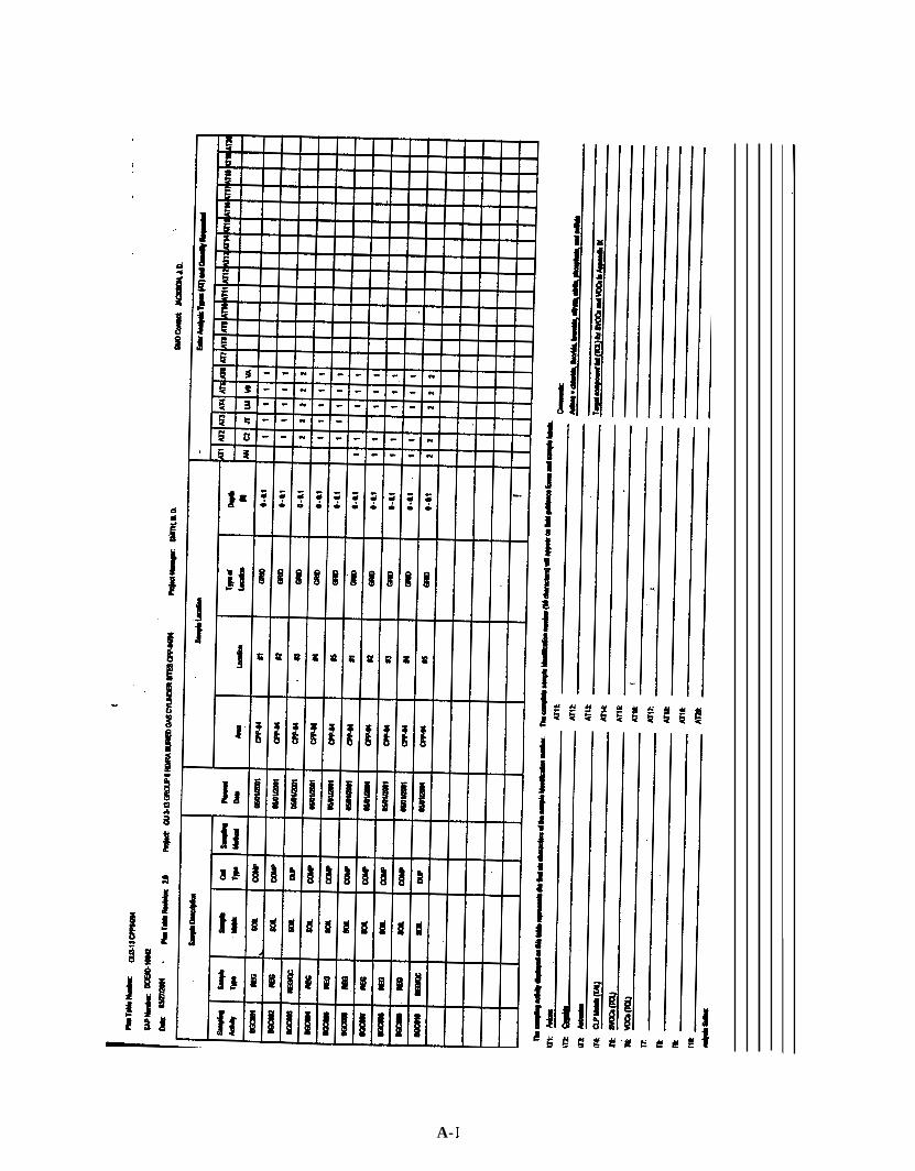
The INEEL Sample Management Office (SMO) will assign a unique 10-character identifier to each sample collected during the investigation. The first three characters of each identifier for both location investigations are BIG. The fourth, fifth, sixth, seventh, and eighth characters identify the sample location and the sequence of sampling (if collocated duplicates are taken from a single location). The ninth and tenth characters identify the type of analyses being performed on that sample. If additional samples are collected in the field, the field team leader (FT’L) is responsible for contacting the SMO for additional sample identification numbers and to ensure use of the identification scheme described in this section.
4.3 Sample Documentation and Management
The FTL will control and maintain all field documents and records, and submit the required documents to the Administrative Record and Document Control Office at the conclusion of the project. Sample documentation, shipping, and custody procedures for this project are based on EPA-recommended procedures that emphasize careful documentation of sample collection and sample transfer. The appropriate information pertaining to each sample will be recorded in accordance with ER MCP-23 1, “Logbooks;” MCP-244, “Chain of Custody Sample Handling and Packaging for CERCLA Activities;” and the QAPjP (DOE-ID 1997). The person designated to complete the sample or FTL logbook will record items such as resembling safety meeting notes, weather, and general project notes in the logbook, as appropriate. Proper handling, management, and disposal of samples under the control of
managed, and disposed of in accordance with MCP-2864, “Sample Management.” ‘ Bechtel BWXT Idaho, LLC (BBWI) or its subcontractors are essential. Samples will be handled,
If it becomes necessary to revise these documents, a document action request (DAR) will be executed in accordance with MCP-230, “Environmental Restoration Document Control Interface.” DARs could include additional analyses that may be necessary to meet appropriate waste acceptance criteria.
4-2
5. SAMPLE HANDLING AND ANALYSIS, WASTE DISPOSAL, AND WASTE M IN1 MlZATlON
5.1 Sample Handling and Analysis
The container volumes, types, holding times, and preservative requirements for samples being collected under this characterization plan are listed in Table 5-1.
All containers will be pre-cleaned (as certified by the manufacturer), using the appropriate EPA-recommended cleaning protocols for the bottle type and sample analyses. Extra containers will be available in case of breakage, contamination, or the need to collect additional samples. Printed labels will contain the name of the project, sample identification number, location, depth, unique bar code, and requested analysis. Following collection, the date and time of collection and the sampler’s initials will be recorded on the sample label using a waterproof black marker. The samples will be placed in coolers with blue ice while awaiting preparation and shipment to the appropriate laboratory. Samples will be prepared and packaged in accordance with MCP-3480, “Environmental Instructions for Facilities, Processes, Materials, and Equipment.”
No radioactivity is expected in the samples from either site. If necessary, a single sample from each site may be sent for a 20-minute gamma screen to determine the concentration of radionuclides present and the shipping classification. Gamma screens will be performed by the Radiation Measurements Laboratory at the Test Reactor Area (TRA).
5.2 Waste Disposal
Waste storage and disposal will be coordinated with the appropriate waste generator services interface to ensure compliance with applicable waste characterization, treatment, and disposal regulations. This includes writing INEEL Form 0435.39, Waste Determination and Disposition Form (WDDF), before treatment or disposal of any solid waste from this project. In addition, record keeping will be conducted in accordance with MCP-557, “Managing Records.” The investigation-derived waste (IDW) produced during sampling will include PPE, sampling supplies, and decontamination water. For each waste stream produced, a WDDDF will be prepared and documented before disposal of the waste. Waste and excess material management will be addressed in the Group 6 Waste Management Plan, and the Idaho National Engineering Laboratory (INEEL) Reusable Property, Recyclable Materials, and Waste Acceptance Criteria (DOE-ID 1999), MCP-3475, “Temporary Storage of CERCLA-Generated Waste at the INEEL,” and MCP-3472, “Identification and Characterization of Environmentally Regulated Waste.”
5.2.1 Solid Waste Management
Solid waste generated during the sample activities includes PPE trash and miscellaneous trash, such as wipes and packaging. Waste that does not come into direct contact with the sampled media or sampling equipment can be disposed of as non-conditional “cold” waste at the INEEL Landfill Complex.
All PPE and other disposal material directly used in sampling, decontamination, etc. will be treated using the methods recommended by Waste Generator Services (WGS). As necessary, containers of waste will be labeled “CERCLA IDW” under the direction of WGS and stored at the site inside the CERCLA waste storage unit, until analytical results are received for the waste. At that time, the proper disposition of the waste will be coordinated with WGS.
5-1

In the unlikely event that hazardous, radioactive waste is generated, it will be disposed of at the Radioactive Waste Management Complex (RWMC). Individual waste streams destined for disposal at RWMC will be approved and prepared for disposal in accordance with INEEL criteria.
5.2.2 Soil Specific Waste Management
Off-site laboratories will dispose of both altered and unaltered samples, as contractually required. Sample material from 20-minute gamma screens will be restored to the collection site if consistent with the final remedy of the site. If samples must be returned from the laboratory, only unused, unaltered samples in the original containers will be accepted. These samples will be managed per PRD-5035, “Temporary Storage of CERCLA-Generated Waste at the INEEL,” and will be treated and disposed of in accordance with regulations based on the concentrations detected. Although no samples are expected to be returned from any laboratory, all samples are expected to be eligible for return to the collection site. Disposition of samples that are returned (for whatever reason) and that cannot be restored to a collection site will be coordinated with the appropriate waste generator interface to ensure compliance with applicable waste characterization, treatment, and disposal regulations.
Decontamination solutions used in small quantities may include deionized water, detergent, and isopropanol. It is anticipated that no decontamination fluids that require containment will be generated during sampling. Excess deionized water, detergent, and isopropanol will be allowed to drain onto the ground near the feature that is being sampled.
5.3 Waste M i n i m iza t i on
As part of the pre-job briefing, waste reduction philosophies and techniques will be emphasized, and personnel will be encouraged to continuously attempt to improve methods. No one will use, consume, spend, or expend equipment or materials thoughtlessly or carelessly. Practices to be instituted to support waste minimization include, but are not limited to, the following:
Restrict material (especially hazardous material) entering control zones to only material needed to perform the work
Substitute recyclable or reusable items when practical
Segregate contaminated from uncontaminated waste
Segregate reusable items such as PPE and tools.
5-2
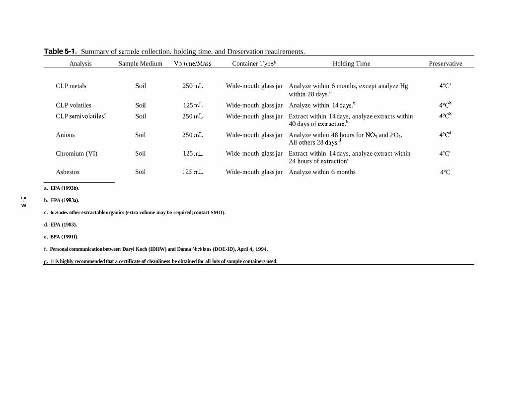
Table 5-1. Summarv of samDle collection. holding time. and Dreservation reauirements.
Analysis Sample Medium VolumeMass Container Typeg Holding Time Preservative
CLP metals Soil 250 mL Wide-mouth glass jar Analyze within 6 months, except analyze Hg 4"ca
CLP volatiles Soil 125 mL Wide-mouth glass jar Analyze within 14 days.b 4"Cb
CLP semivolatiles' Soil 250 mL Wide-mouth glass jar Extract within 14 days, analyze extracts within 4"Cb
within 28 days."
40 days of extraction.b
Anions
Chromium (VI)
Asbestos
Soil 250 mL Wide-mouth glass jar Analyze within 48 hours for NO3 and PO4. 4"Cd All others 28 daysd
Soil
Soil
125 mL
125 mL
Wide-mouth glass jar Extract within 14 days, analyze extract within 24 hours of extraction'
Wide-mouth glass jar Analyze within 6 months
4°C'
4°C
a. EPA (1993b).
Y b. EPA (1993a). W
c. Includes other extractable organics (extra volume may be required; contact SMO).
d. EPA (1983).
e. EPA(1991f).
f. Personal communication between Daryl Koch (IDHW) and Donna Nicklaus (DOE-ID), April 4, 1994.
g. It is highly recommended that a certificate of cleanliness be obtained for all lots of sample containers used.

6. QUALITY ASSURANCE OBJECTIVE
The objective of this investigation is to provide sufficient characterization information to determine whether further characterization or remedial actions are needed. This characterization plan is used in conjunction with the QAPjP (DOE-ID 1997). These documents present the functional activities, organizations, and Quality Assurance/Quality Control (QNQC) protocols necessary to achieve the specified DQOs. Project-specific quality requirements not addressed in the QAPjP or elsewhere in this document are discussed below.
6.1 Quality Control Sampling
The purpose of collecting and analyzing QNQC samples is to assess the acceptability of the bias and precision of the data in addition to the mean concentrations. The number and type of QNQC samples required during remedial investigations are specified in the QAPjP. The specific QNQC requirements for this project are discussed below.
6.1.1 Quality Assurance and Quality Control Sampling
As outlined in the QAPjP (DOE-ID 1997), QA objectives are specified so that the data produced are of a known and sufficient quality to meet the specified DQOs. Quantitative objectives (such as precision, accuracy, completeness measurements, and method detection limits) and qualitative objectives (such as representativeness and comparability) are described in the QAPjP. The QNQC samples to be collected and the analyses planned are shown in Appendix A.
6.1.2 Precision and Accuracy
During post-removal sampling activities, one field duplicate soil sample will be collected from the excavation area at each site. The duplicate samples will be analyzed to evaluate sampling variability and precision. They will also be analyzed for the same suite of analytes as regular samples. Laboratory precision and accuracy are part of the data validation criteria against which the results are evaluated. In general, bias (accuracy) in the field is difficult to assess and in this investigation will be qualitatively evaluated, based on the results of field and equipment blanks.
6.1.3 Method Detection Limits
. The method detection limits for COPCs are outlined in the QAPjP and are agreed upon between the SMO and analytical laboratory, as outlined in the project Task Order Statement.
6.1.4 Critical Samples
Per the QAPjP, critical samples are those samples required to achieve project objectives or limits on decision error limits. Non-critical samples are for information. For this project, five samples from each population are required to statistically achieve the stated goals. Consequently, all regular samples will be considered critical.
6.1.5 Representativeness
The sampling and analysis methodology used for this investigation are considered adequate for obtaining representative sample material and representative data results. At the conclusion of the project, the representativeness of the collected data will be qualitatively evaluated by confirming whether the sampling designs were adhered to and DQOs were met.
6- I

6.1.6 Comparability
Data comparability will be assessed by evaluating the sampling design, sampling procedures, sample handling, and laboratory analyses for each sample. The methods used for sample collection are considered to be comparable within each site. The analytical methods are deemed comparable with other investigations using SW-846 methodology.
6.1.7 Completeness
Completeness is the measure of the quantity of the usable data collected during an investigation. The goal for this project is 100% completeness for critical samples.
6.2 Data Validation, Reduction, and Reporting
Data will be acquired, processed, and controlled before input to the Integrated Environmental Data Management System (IEDMS) per MCP-227, “Sampling and Analysis Process for CERCLA and D&D Activities.” For each sample delivery group, a data limitation and validation report, which includes copies of COC forms, sample results, and validation flags, will be generated. All data limitation and validation reports associated with a site will be transmitted to the EPA and DEQ for review. All definitive data will be uploaded to the Environmental Restoration Information System (ERIS). The results of the complete data reduction and interpretation (including QNQC results) will be provided in the OU 3-13 report.
The SMO will validate the data to a Level B analytical method data validation as defined in TPR-79 (SOP- 12.1. l), “Levels of Analytical Method Validation.” As applicable, the analytical method data validation will be conducted in accordance with TPR-80 (SOP-12.1.2), “Radiological Data Validation;” TPR-132, “Inorganic and Miscellaneous Chemical Analysis Data Validation;” TPR-8 1 (SOP-l2.1.3), “Validation of Volatile Organic Gas Chromatographic Data;” and TPR-82 (SOP-l2.1.4), “Validation of Gas Chromatographic Data.” Validated data are entered in the IEDMS and uploaded to ERIS.
6-2

7. PROJECT ORGANIZATION
The project organization and individuals associated with this investigation are shown in Figure 7-1.
For a position indicating “to be determined,” a logbook entry will be made to show the name of the individual who performs that function. Responsibilities for project personnel are described in the OU 3-13, Group 6 HASP.
7- 1

7-2

DOE-ID, 199 1, Federal Facility Agreement and Consent Order for the Idaho National Laboratory, 1088-06-29-120, U.S. Department of Energy Idaho Operations Office, Environmental Protection Agency Region 10, State of Idaho Division of Environmental Quality.
DOE-ID, 1997, Quality Assurance Project Plan for Waste Area Groups 1, 2, 3, 4, 6, 7, and 10 and Inactive Sites, DOW-10587, Revision 5.
DOE-ID, 1999, Idaho National Engineering Laboratory Reusable Property, Recyclable Materials, and Waste Acceptance Criteria, DOE/ID- 1038 1, U.S. Department of Energy, Idaho Operations, Revision 10, November.
DOE-ID, 2000, Remedial DesigdRemedial Action Scope of Work for Waste Area Group 3, Operable Unit 3-13, DOE/ID-10721, Rev. 1, February.
EPA, 1989, Soil Sampling Quality Assurance User’s Guide, EPA/600/8-89/046.
EPA, 1991, Soil Sampling and Analysis for Volatile Organic Compounds, EPA/540/4-9 1/001.
EPA, 1992a, Guidance for Data Usability in Risk Assessment (Part A), Office of Emergency and Remedial Response, Washington, D.C., 9285.7-09A.
EPA, 1992b, Preparation of Soil Sampling Protocols: Sampling Techniques and Strategies, EPA/600/R- 921 1 28.
EPA, 1994. Guidance for the Data Quality Objectives Process, EPA QAIG-4, EPA/600/R-96/055, Septenoer.
EPA, 1996, Guidance for Data Quality Assessment, EPA QNG-9, EPA/60O/R-96-084.
INEEL, 2000a, Health and Safety Plan for Preliminary Characterization and Post-RD/RA Sampling for WAG 3, OU 3-13, Group 6 Buried Gas Cylinders, INEEL/EXT-2000-00270, Rev. 1, October.
INEEL, 2000b, Hazard Classification for Remediation of OU 3-13 Group 6 RD/RA Buried Gas Cylinder Sites: CPP-84 and CPP-94, INEEWEXT-2000-000254, Rev. 1, May.
Jones, R. K., 1996, Waste Certification Plan for the Environmental Restoration Program, INEIJ96-0043, Lockheed Martin Idaho Technologies Company, April.
MCP-227, “Sampling and Analysis Process for CERCLA and D&D Activities,” INEEL Companywide Manual 18, Closure Management, current revision.
MCP-230, “Environmental Restoration Document Control Center Interface,” INEEL Environmental Restoration Management Control Procedure, revision 5.
MCP-23 1, “Logbooks,” INEEL Environmental Restoration Management Control Procedures, current revision.
MCP-24 1, “Preparation of Characterization Plans,” INEEL Environmental Management Control Procedures, current revision.
8-1

MCP-242, “Obtaining Laboratory Services for Environmental Management Funds Activities,” INEEL Companywide Manual 18, Closure Management, current revision.
MCP-244, “Chain-of-Custody, Sample Handling, and Packaging for CERCLA Activities,” INEEL Companywide Manual 18, Closure Management, current revision.
MCP-557, “Managing Records,” INEEL Companywide Manual 1, General Administration and Information, current revision.
MCP-2864, “Sample Management,” INEEL Companywide Manual 18, Closure Management, current revision.
MCP-3472, “Identification and Characterization of Environmentally Regulated Waste,” Companywide Manual 17, Waste Management, revision 0.
MCP-3480, “Environmental Instructions for Facilities, Processes, Materials, and Equipment,” INEEL Companywide Manual 8 , Environmental Protection and Compliance, current revision.
Pitard, F.F., 1989. Pierre Cy’s Sampling Theoly and Sampling Practice, CRC Press, Inc.
PRD-5035, “Temporary Storage of CERCLA-Generated Waste and the INEEL,” INEEL Companywide Manual 8, Environmental Protection and Compliance, revision 0.
SOP-12.1.2, “Radiological Data Validation,’’ Rev. 1, EG&G Idaho ER&WM Department, Sample Management Office, January 1993.
SW-846, 1986, “Test Methods for Evaluating Solid Waste: PhysicaYChemical Methods,” Environmental Protection Agency, Office of Solid Waste and Emergency Response.
TPR-79 (SOP-12.1. l), “Levels of Analytical Method Data Validation,’’ INEEL Environmental Technical Procedure, current revision, current revision.
TPR-80 (SOP-12.1.2), “Radiological Data Validation,’’ current revision.
TPR-8 1 (SOP-12.1.3), “Validation of Volatile Organic Gas Chromatographic Data,” current revision.
TPR-132, “Inorganic and Miscellaneous Chemical Analysis Data Validation,’’ current revision.
8-2

Appendix A
Sampling and Analysis Plan Tables
A- I


