Project: Double Deck Date: 03/08/2007 Version: 1.21 Preliminary Evaluation of Double Deck & Extra Long Train Operations Project: DfT Capacity Development Options Project: DfT Capacity Development Options –Double Deck and Extra Long Train Operations Task Deliverable Element Lead: Andrew Coombes Signature Name: Bob Murton Job Title: Enhancement Engineer (Civils) Prepared By Date: 24/07/07 Endorsed By Name: Andrew Coombes 1 of 89
Transcript
Project: Double Deck Date: 03/08/2007
Version: 1.21
Preliminary Evaluation of Double Deck
& Extra Long Train Operations
Project: DfT Capacity Development Options
Project: DfT Capacity Development Options –Double Deck and Extra Long Train Operations
Task Deliverable Element Lead: Andrew Coombes
Signature
Name: Bob Murton
Job Title: Enhancement Engineer (Civils)
Prepared By
Date: 24/07/07
Endorsed By Name: Andrew Coombes
1 of 89
Project: Double Deck Date: 03/08/2007
Version: 1.21
Job Title: Head of Enhancement Engineering
Date: 24/07/07
2 of 89
Project: Double Deck Date: 03/08/2007
Version: 1.21
DfT Foreword
In developing the White Paper ‘Delivering a Sustainable Railway’ the Department for Transport asked Network Rail to carry out some preliminary work to assess the case for longer or double deck trains as a way of providing additional carrying capacity on the rail network in the longer term.
The work was to focus on a range of medium distance corridors where it was possible that longer term demand trends could result in further crowding. Whilst accepting that other parts of the strategy, such as cab based signalling, could provide additional capacity it was important to assess what other solutions could be used.
Importantly the study was also asked to consider the passenger acceptability of any train design that resulted. Previous designs of Double Deck trains which used the existing gauge were criticised as being cramped and stuffy. The White Paper makes it clear that over time passenger expectations of the railway are likely to increase and these considerations needed to be included within new train designs.
The report that follows is a high level assessment of the case for longer or double deck trains. The report does not attempt to answer every question, and in some cases innovative designs could tackle some of the issues raised. But the report attempts to highlight the key issues to be considered when assessing double deck or extra long trains and makes conclusions based on an initial assessment of implementation costs and additional capacity delivered whilst considering the needs of passengers.
1.1 SUMMARY OF FINDINGS FOR ‘UK DOUBLE DECK VEHICLE’ ................................... 7 1.2 SUMMARY OF ROUTES ASSESSED FOR DOUBLE DECK ......................................... 9 1.3 SUMMARY OF ASSESSMENT OF LONG TRAIN OPERATION AND WORKS ................. 10 1.4 SUPPORTING ISSUES AND COMMENT ................................................................ 11
3.1 CHARACTERISTICS OF DOUBLE DECK VEHICLE.................................................. 15 3.2 CONCEPT DESIGN FOR UK DOUBLE DECK VEHICLES ......................................... 16 3.3 EXTRA LONG TRAIN OPERATION ...................................................................... 17 3.4 EVALUATION OF WORK SCOPE......................................................................... 18 3.5 COSTING OF WORK......................................................................................... 18
4.1 KEY FEATURES OF EUROPEAN MAINLAND DOUBLE DECK ROLLING STOCK ............. 20 4.2 KEY EXTERNAL DIMENSIONS OF CURRENT UK PASSENGER ROLLING STOCK.......... 21 4.3 KEY INTERNAL DIMENSIONS AND LAYOUT OF CURRENT UK PASSENGER ROLLING STOCK .................................................................................................................... 22 4.4 PROVISION FOR STANDING PASSENGERS IN CURRENT UK ROLLING STOCK ........... 23 4.5 CONCEPT DESIGN FOR UK PROFILE DOUBLE DECK VEHICLE ............................. 24 4.6 POTENTIAL FOR USE OF STANDARD EUROPEAN MAINLAND VEHICLES.................. 28
5 ESTIMATE OF SEATING CAPACITY OF UK PROFILE DOUBLE DECK VEHICLES ............................................................................................................... 29
5.1 BASE ANALYSIS VEHICLE ................................................................................. 29 5.2 ANALYSIS OF THE 23M VEHICLE........................................................................ 29 5.3 ANALYSIS OF THE 20M VEHICLE........................................................................ 29 5.4 COMPARISON OF SEATING CAPACITIES BETWEEN UK SAMPLE VEHICLES AND PROPOSED UK DOUBLE DECK VEHICLE ...................................................................... 30 5.5 ASSESSMENT OF SEATING CAPACITY FOR PROPOSED UK PROFILE DOUBLE DECK TRAIN FORMATIONS ................................................................................................. 31
6 LONG TRAINS .................................................................................................. 33
7 COMPARISON OF TRAIN CAPACITIES .......................................................... 35
8.1 DOUBLE DECK – WORK ITEMS ......................................................................... 36 8.2 LONG TRAIN WORK ITEMS ............................................................................... 40 8.3 COST ESTIMATION .......................................................................................... 40
9 SUMMARY OF INFRASTRUCTURE ITEMS..................................................... 43
4 of 89
Project: Double Deck Date: 03/08/2007
Version: 1.21
APPENDIX A – FRENCH NATIONAL RAILWAYS CLASS Z20500 EMU.............. 46
APPENDIX B - GERMAN RAILWAYS BOMBARDIER DOUBLE DECK PUSH PULL COACHES..................................................................................................... 51
APPENDIX C - COMPARISON OF MAINLAND EUROPE PASSENGER VEHICLE DIMENSIONS .......................................................................................................... 52
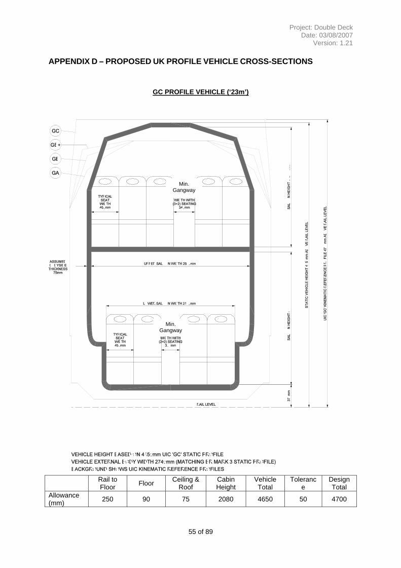
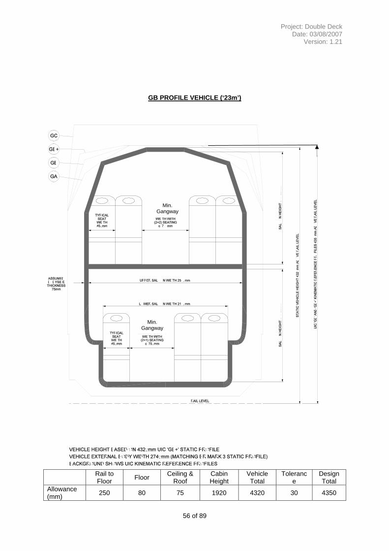
APPENDIX D – PROPOSED UK PROFILE VEHICLE CROSS-SECTIONS........... 55
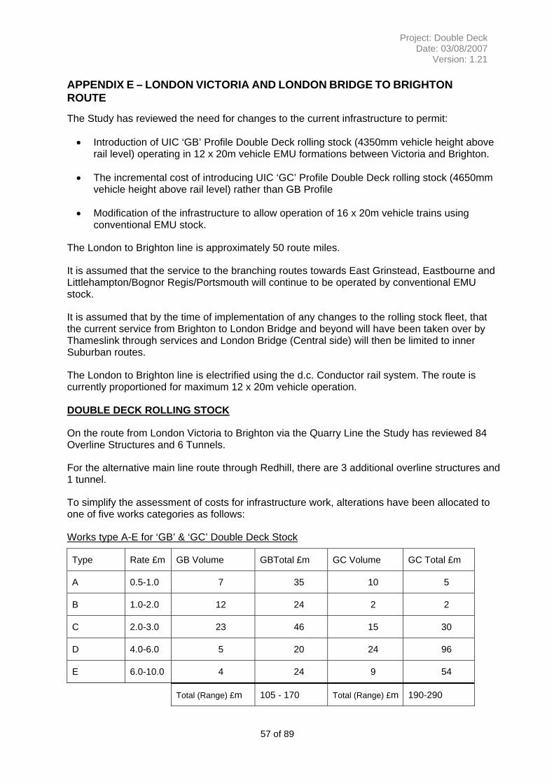
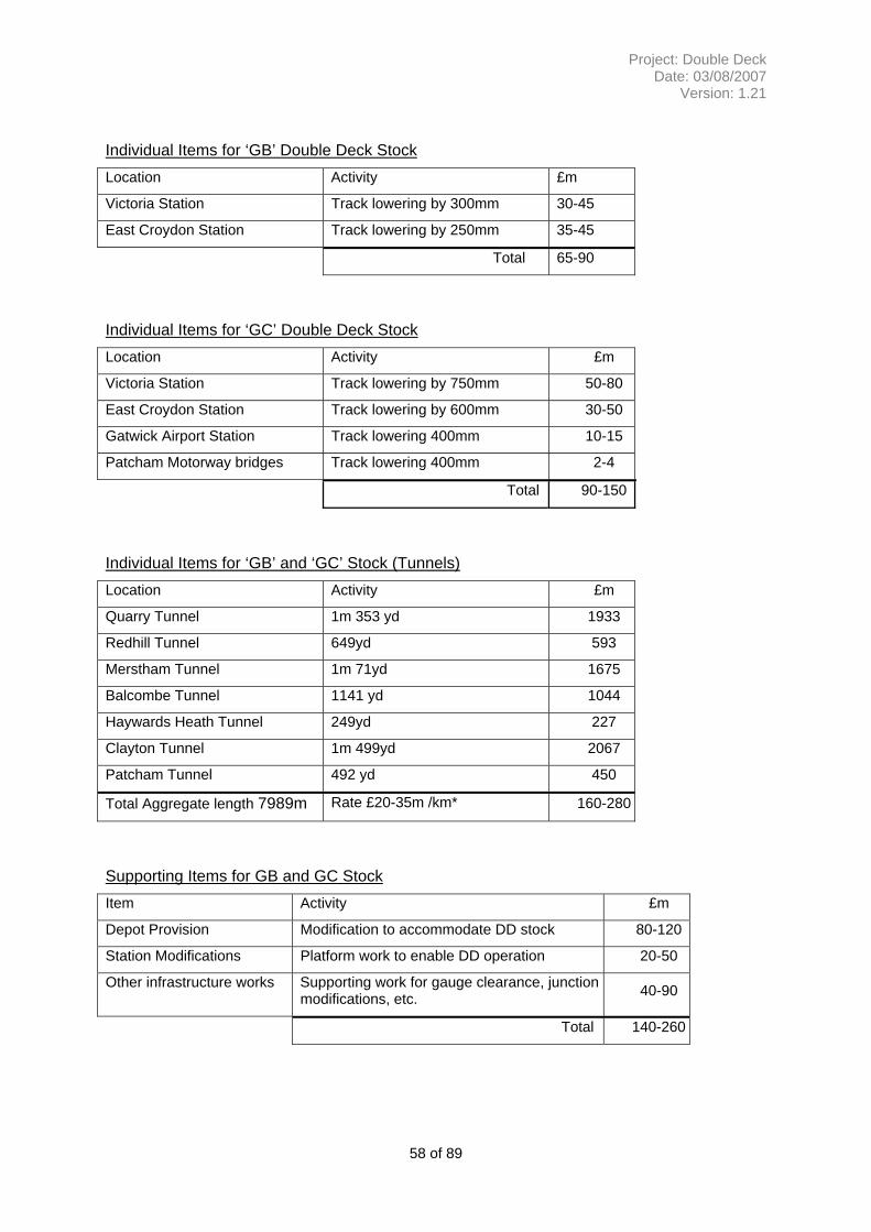
APPENDIX E – LONDON VICTORIA AND LONDON BRIDGE TO BRIGHTON ROUTE..................................................................................................................... 57
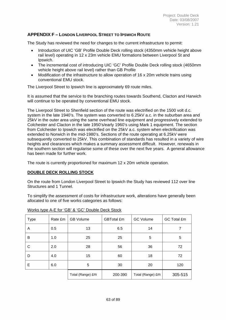
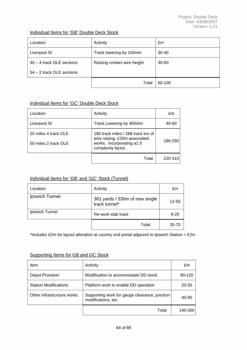
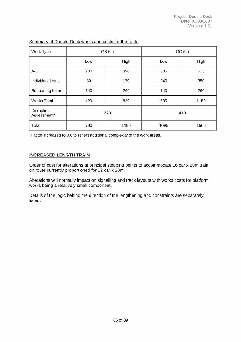
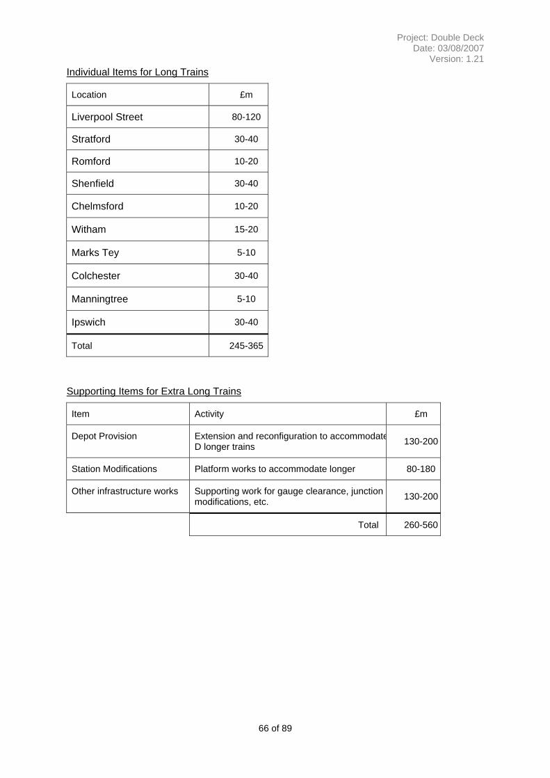
APPENDIX F – LONDON LIVERPOOL STREET TO IPSWICH ROUTE................ 63
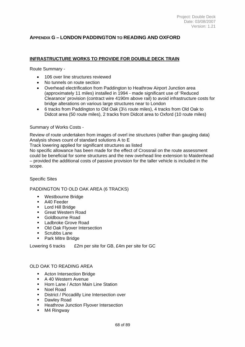
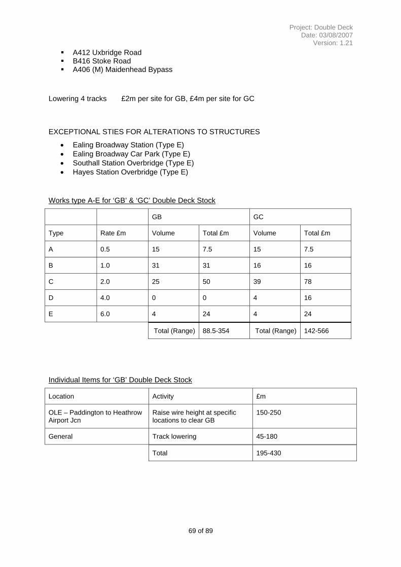
APPENDIX G – LONDON PADDINGTON TO READING AND OXFORD .............. 68
APPENDIX H – LONDON WATERLOO TO SOUTHAMPTON ............................... 71
APPENDIX I – RISKS AND OPPORTUNITIES REGISTER.................................... 75
APPENDIX J - DIMENSIONAL RELATIONSHIP OF OVERHEAD LINE ELECTRIFICATION TO OVERLINE STRUCTURES .............................................. 76
APPENDIX K - BACKGROUND TO MAINLAND EUROPE VEHICLE GAUGES... 78
APPENDIX L - APPLICATION OF THE ‘UIC’ REFERENCE PROFILES IN THE U.K. .......................................................................................................................... 81
APPENDIX M - DEVELOPMENT OF VEHICLE AND STRUCTURE GAUGES IN THE U.K…………………………………………………………………………………….80
APPENDIX N SUMMARY OF UK PASSENGER ROLLING STOCK DIMENSIONS…………………………………………………...………………………….84
APPENDIX O – SUMMARY OF UK PASSENGER SEATING ARRANGEMENTS AND CAPACITIES…………………………………………………………………………86
5 of 89
Project: Double Deck Date: 03/08/2007
Version: 1.21
1 EXECUTIVE SUMMARY
This concept study considers the alternatives of using Double Deck vehicles or longer trains (12-16 coaches) to address the increased capacity needed for a selection of London outer suburban routes. These routes have high growth forecasts and as a base it is assumed that the services will have expanded to12 coach operation. The selected routes also provided a range of current infrastructure configurations to test the proposals against. (Inner suburban, London, routes were not considered as many have more scope for growth by increasing to 10 or 12 car length.)
For Double Deck the study proposes a vehicle which is considered to be a best fit of the available infrastructure and still providing the expected quality of passenger environment. To establish a suitable ‘design’ the vehicles currently in use, or being developed, in Europe were reviewed and an existing French vehicle used as a design reference. This UK proposed vehicle was then assessed on each route and the works required to accommodate it were assessed and costs established at an outline level. The conclusion of this analysis is that the constraints on vehicle size (width) and length (curvature and bogie spacing) result in a relatively inefficient vehicle with seating benefits around 8% per 20m vehicle or 24% per 23m vehicle. These compare with values of about 50% for a ‘typical’ European vehicle. The comparison costs for route conversions range from £500m to around £1,300m with a work scope dominated by civil engineering activity.
For Longer trains the study used a train sized at 16 coaches, which would provide a passenger carrying benefit of around 33%, to assess the impact on the infrastructure facilities. Again scope and comparison costs were collated at an outline level for two routes and ranged from £720m to £1200m with work scopes which include significant specialist rail construction costs. However, no detailed consideration was given to the passenger dispersal and handling issues which are considered a significant issue with the application of long trains on relatively short journey lengths.
The scope and costs for the associated works have been derived from existing asset data supported by ad hoc site specific information, the costs are then allocated on the basis of a set of typical activities and a separate assessment of disruption. All the figures exclude the cost of the vehicles and any costs to strengthen traction power supplies. The overall figures are therefore valid as a means to assess the proposals but not as an anticipated scheme cost.
In conclusion the benefits from the double deck solution on the existing network do not offset the relatively low volume of additional capacity generated, the significant disruption required to adapt the routes and the resulting long term inflexibility of operation. Double deck would be a viable solution for a new-build route where a more efficient vehicle size could be specified. Alternatively if a higher density seating pattern were to be acceptable on these longer journeys then the case is improved. However, some of the engineering solutions require validation in terms of practicality and design assessment. These uncertainties transfer into the disruption estimate which may well be much higher than the general assumption used in the study. The longer train solution is a comparable first cost, but the issue of how much ‘longer’ to optimise capacity gain, land take and cost remains open. Further work to identify the trade off point would give a secure additional capacity at an optimal cost. Other favourable features are that the vehicles can be more flexibly used in shorter formations and opportunities exist for the integration of works, over time, with renewal projects. The concerns about crowd control and achieving an even loading require further
6 of 89
Project: Double Deck Date: 03/08/2007
Version: 1.21
consideration and solutions applying as stations are re-developed. Train operators could lead on these solutions, to achieve an even load along the train with comparable dwell times. Moving forward the more detailed evaluation of longer train lengths and how to provide additional trains by better train performance, improved train control systems or the creation of more through running in the capital could offer better solutions.
Route Cost for Double Deck Operation £m *1
Additional seats *3 (LD 2+2 HD 3+2)
Cost per seat for
an average vehicle £m *2
Cost for Long Train Operation £m *1
Additional seats *3 (LD 2+2 HD 3+2)
Cost per additional person carried £m *2
London Victoria/ London Bridge to Brighton (20m vehicles)
650-990
(Mid 820)
LD 96
HD 216
LD 8.5
HD 3.8
770-1225
(Mid 1055)
LD 240
HD 270
4.4
3.9
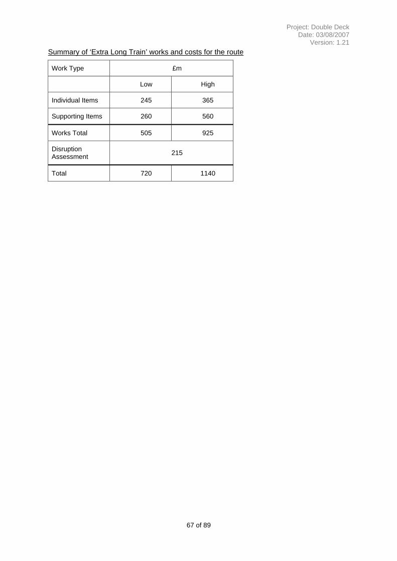
Liverpool St – Colchester and Ipswich (23m vehicles)
580-960
(Mid 770)
LD 252
HD 102
LD 3.9
HD 7.5
720-1140
(Mid 930)
LD 260
HD 360
3.6
2.6
London Waterloo to Southampton (20m vehicles)
500-1140
(Mid 820)
LD 96
HD 216
LD 8.9
HD 3.8
London Paddington to Reading and Oxford (23m vehicles)
650-1260
(Mid 955)
LD 252
HD 102
LD 3.8
HD 9.4
*1 Comparison costs with disruption included as an overlay *2 Person carried assessment is used for ranking only (i.e. takes no account of service). The
ratio is the additional seats and the mid point in the range of costs. *3 The increased seat number is based on Double Deck 12 car operation (2*6car) compared to
conventional 12 car operation.
Table 1.1 Summary of costs for Double Deck and Long Train Operation
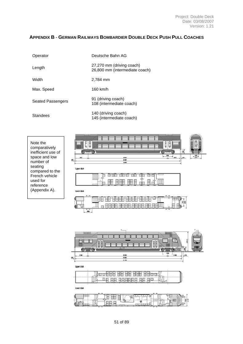
1.1 Summary of Findings for ‘UK Double Deck Vehicle’
The ‘UK Double Deck Vehicle’ was derived by considering vehicles from mainland Europe, making key assumptions about the extent of changes which would be ‘affordable’ to our infrastructure and developing a credible outline vehicle and seating plan. This vehicle was then used to establish, to a greater level of detail, the work required to make the routes available for Double Deck operation.
The vehicles used in the review fell into two overall categories, those built to suit the UIC ‘GB’ Reference Profile at 4320mm above rail level (French Railways gauge) and the UIC ‘GC’ Reference Profile at 4650mm (German and Central European gauge). For UK a body height of around 3800mm is typical. The body width of modern European nominal 26 metre length double deck vehicles at 2800mm is very similar to that of recent UK rolling stock with a body length of 20.25 metres and would allow a similar seating layout with either a high-density (3+2) or low-density (2+2) format. However, the European bogie pivot point dimension of 20m or more is far more favourable to an efficient seating layout than the 14.17m used on British 20m stock.
7 of 89
Project: Double Deck Date: 03/08/2007
Version: 1.21
In establishing a credible ‘UK’ gauge the limiting factor on height was the assessment of the headroom available for passengers in each floor of the carriage. To derive this consideration was given to other, comparable, transport modes and a height of around 1920mm chosen. This is similar to the smaller London Underground tube stock (e.g. the Victoria Line) but more generous than the typical top deck of a bus. To minimise the overall height low floors are proposed which severely restrict the space for ancillary and traction equipment on the vehicles. For the vehicle width, this was bound by the existing platform dimensions on grounds of both cost and operational flexibility. For the bogie pivot points the distance was held at 14.17m for 20m stock and 16m for 23m stock. This effectively deemed that wholesale repositioning of both curves and curved platforms (e.g. a possible rebuilding Clapham Jcn) unaffordable. The resulting body width was between 2800mm for a 20.25m vehicle and 2740mm for a 23m. This gave a lower seating layout of either a high density 2+2 or an acceptable spacing but low capacity 1+2.
The conclusion of this analysis, combined with the overall structure of the analysis vehicles, effectively confirmed that a vehicle fitting within the existing overall static height of 3990mm would not provide acceptable headroom. This conclusion also addresses the objective to improve the passenger experience and provide for a population that is taller than it has been historically and forecast to have an increasing body mass index.
The adoption of an existing European profile train is considered uneconomic because of the extensive infrastructure work required to accommodate the longer bogie centres with the resulting implications for end throw and mid throw. Work would also be required to the platforms to suit their highly efficient end vestibule arrangements and hence release width for the lower deck. These alterations would be further complicated by the need to continue to support the use of the existing rolling stock. One feature, seen in some European stock, that would be beneficial is the through connection at the high level, but was not assessed in this report.
Train *1
Average Seats per DD Vehicle
Average Seats per Single Deck Vehicle *2
% Additional seats in DD
Seating Configuration Upper/Lower
Height (mm) Width (mm) Bogie Centres (m)
‘UK Double Deck Vehicle’ (20m) Low Density
68 60 8 2+2 2+1
4320 2800
14 ‘UK Double Deck Vehicle’ (20m) High Density
86 68 26 3+2 2+2
4320 2800
14 ‘UK Double Deck Vehicle’ (23m) Low Density
86 65 24 2+2 2+1
4320 2740
16 ‘UK Double Deck Vehicle’ (23m) High Density
98 90 9 3+2 2+1
4320 2740
16 Euro GB Profile (26m) High Density
146 90 62 3+2 3+2
4320 2800
20 Euro GC Profile (26m) Low Density
98 65 50 2+1 2+2
4630 2800
21 *1 Train formations for UK vehicles are average vehicle capacity for 6 car sets *2 Base train is an average vehicle capacity based on a 4 car set
Table 1.2 Capacity and sizing summary of European and ‘UK proposed’ Double Deck Vehicles
8 of 89
Project: Double Deck Date: 03/08/2007
Version: 1.21
Hence a UK profile Double Deck train could provide a 26% additional capacity compared to an equivalent single deck train for a high density (3+2) seating layout or 8% for a low density (2+2) layout based on a nominal 20metre vehicle length. The train size is considered to be practical but has not been fully assessed against all the space requirements for ancillary services and DDA provision which could reduce seating provision. Equally by using the French National Railways (SNCF) 4-car EMU as a reference vehicle some of the generous provision for above deck provision of power equipment (due to the low floor height) could be improved upon to generate more seating space.
1.2 Summary of Routes Assessed for Double Deck
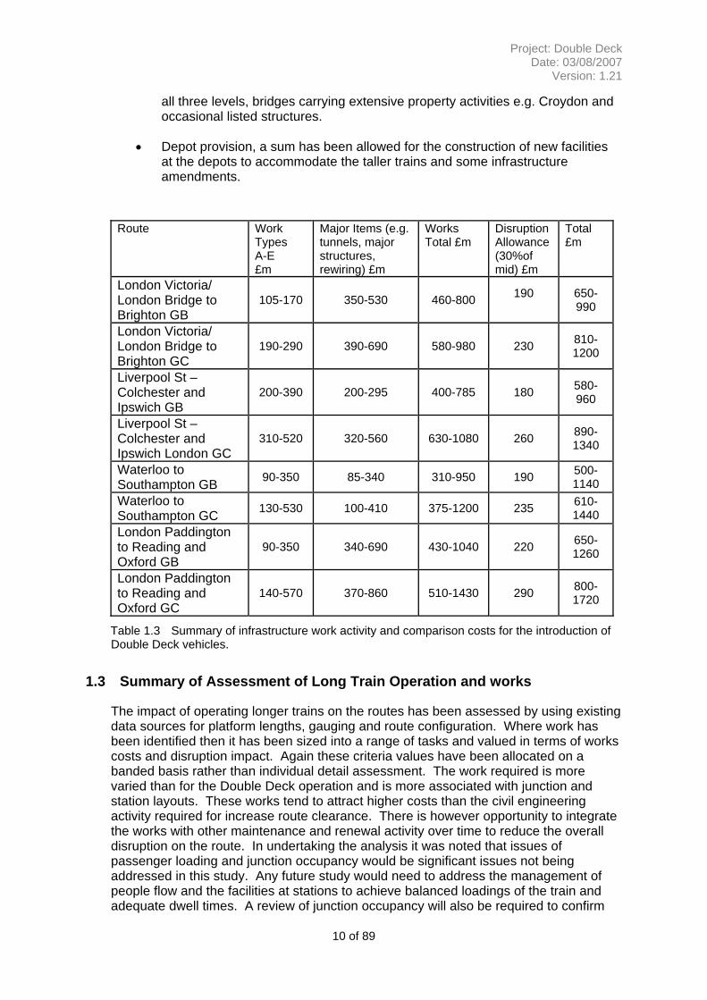
The impact of proposed ‘UK Double Deck vehicle’ on the routes has been assessed by using existing data sources for gauging and route configuration. Where work has been identified then it has been sized into a range of tasks and valued in terms of works costs and disruption impact. Again these criteria values have been allocated on a banded basis rather than individual detail assessment. In assessing disruption reference has been made to other recent major programmes and also the view that there is a ‘credible’ limit to the amount of disruption tolerable on a route e.g. a 6 month closure for a tunnel widening on the Brighton Main line would not be tolerable. Also there are some works for which no credible possession regime / work method could be readily proposed e.g. the raising of the GE overhead line system to ‘GC’ clearance throughout. Where these were identified then an alternative option was followed for the purposes of this report.
The assessments demonstrated a mixture of common themes and route specific issues. The nature and conclusions to the main items are discussed below:-
• On those routes with DC Electrification – London Brighton and London Southampton significant alterations to existing over line structures built prior to the 1960’s and/or lowering of the track formation is required. A substantial lowering of the track level in tunnels would be needed or the construction of a new single track tunnel allowing the existing tunnel to operate as a single line repositioned towards the centre of the tunnel bore.
• For those routes with Overhead Electrification London Ipswich and London Reading: -
o For UIC ‘GB’ vehicles, the raising of the majority of existing over line structures and localised modification to the OLE system over a length of around 500 metres in the vicinity of each structure
o For UIC ‘GC’ vehicles, the raising of the majority of existing over line structures and the modification of the entire overhead line electrification system to achieve the required electrical safety clearance.
• The CTRL main line has been constructed to the mandated UIC ‘GC’ Reference Profile size and the larger 4650mm vehicle height could be operated on this route. Separate platforms have been provided at European platform gauge for international services and UK platform gauge for domestic services.
• In reviewing the bridge, canopy and other overhanging structures the majority (in volume) can be addressed at reasonable cost and possession length. However, there is a number of what could be deemed exceptional structures which have a disproportionate cost. Examples of these include overlapping and interlaced bridges i.e. rail over rail over road where work will be required on
9 of 89
Project: Double Deck Date: 03/08/2007
Version: 1.21
all three levels, bridges carrying extensive property activities e.g. Croydon and occasional listed structures.
• Depot provision, a sum has been allowed for the construction of new facilities at the depots to accommodate the taller trains and some infrastructure amendments.
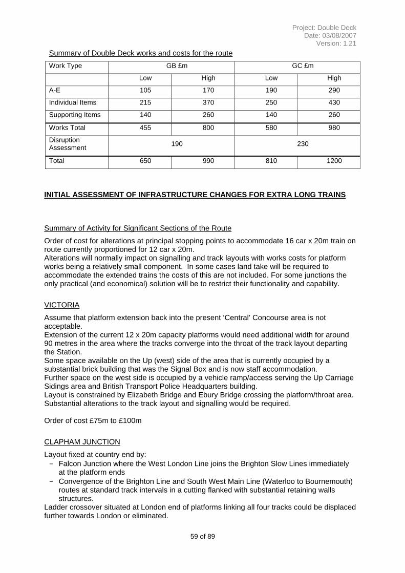
Route Work Types A-E £m
Major Items (e.g. tunnels, major structures, rewiring) £m
Works Total £m
Disruption Allowance (30%of mid) £m
Total £m
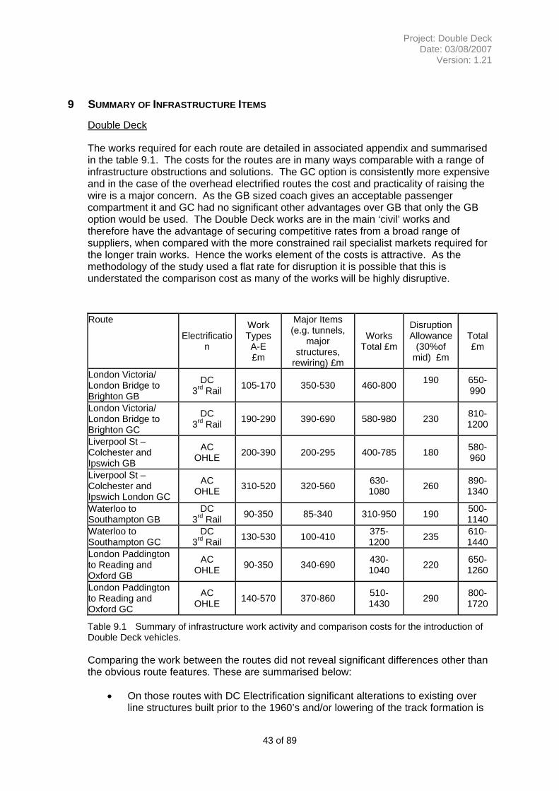
London Victoria/ London Bridge to Brighton GB
105-170 350-530 460-800 190
650-990
London Victoria/ London Bridge to Brighton GC
190-290 390-690 580-980 230 810-1200
Liverpool St – Colchester and Ipswich GB
200-390 200-295 400-785 180 580-960
Liverpool St – Colchester and Ipswich London GC
310-520 320-560 630-1080 260 890-1340
Waterloo to Southampton GB 90-350 85-340 310-950 190 500-
1140 Waterloo to Southampton GC 130-530 100-410 375-1200 235 610-
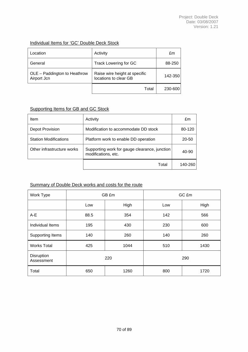
1440 London Paddington to Reading and Oxford GB
90-350 340-690 430-1040 220 650-1260
London Paddington to Reading and Oxford GC
140-570 370-860 510-1430 290 800-1720
Table 1.3 Summary of infrastructure work activity and comparison costs for the introduction of Double Deck vehicles.
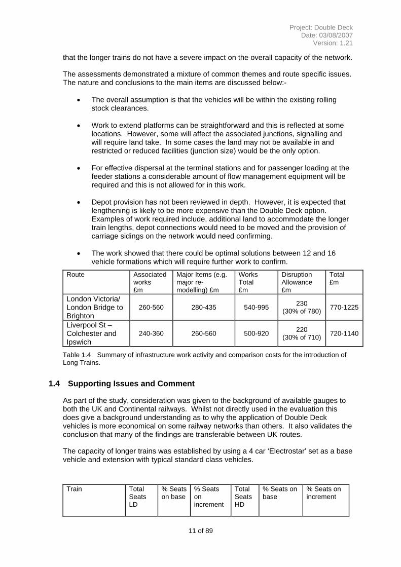
1.3 Summary of Assessment of Long Train Operation and works
The impact of operating longer trains on the routes has been assessed by using existing data sources for platform lengths, gauging and route configuration. Where work has been identified then it has been sized into a range of tasks and valued in terms of works costs and disruption impact. Again these criteria values have been allocated on a banded basis rather than individual detail assessment. The work required is more varied than for the Double Deck operation and is more associated with junction and station layouts. These works tend to attract higher costs than the civil engineering activity required for increase route clearance. There is however opportunity to integrate the works with other maintenance and renewal activity over time to reduce the overall disruption on the route. In undertaking the analysis it was noted that issues of passenger loading and junction occupancy would be significant issues not being addressed in this study. Any future study would need to address the management of people flow and the facilities at stations to achieve balanced loadings of the train and adequate dwell times. A review of junction occupancy will also be required to confirm
10 of 89
Project: Double Deck Date: 03/08/2007
Version: 1.21
that the longer trains do not have a severe impact on the overall capacity of the network.
The assessments demonstrated a mixture of common themes and route specific issues. The nature and conclusions to the main items are discussed below:-
• The overall assumption is that the vehicles will be within the existing rolling stock clearances.
• Work to extend platforms can be straightforward and this is reflected at some locations. However, some will affect the associated junctions, signalling and will require land take. In some cases the land may not be available in and restricted or reduced facilities (junction size) would be the only option.
• For effective dispersal at the terminal stations and for passenger loading at the feeder stations a considerable amount of flow management equipment will be required and this is not allowed for in this work.
• Depot provision has not been reviewed in depth. However, it is expected that lengthening is likely to be more expensive than the Double Deck option. Examples of work required include, additional land to accommodate the longer train lengths, depot connections would need to be moved and the provision of carriage sidings on the network would need confirming.
• The work showed that there could be optimal solutions between 12 and 16 vehicle formations which will require further work to confirm.
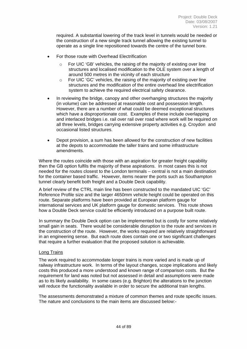
Route Associated works £m
Major Items (e.g. major re-modelling) £m
Works Total £m
Disruption Allowance £m
Total £m
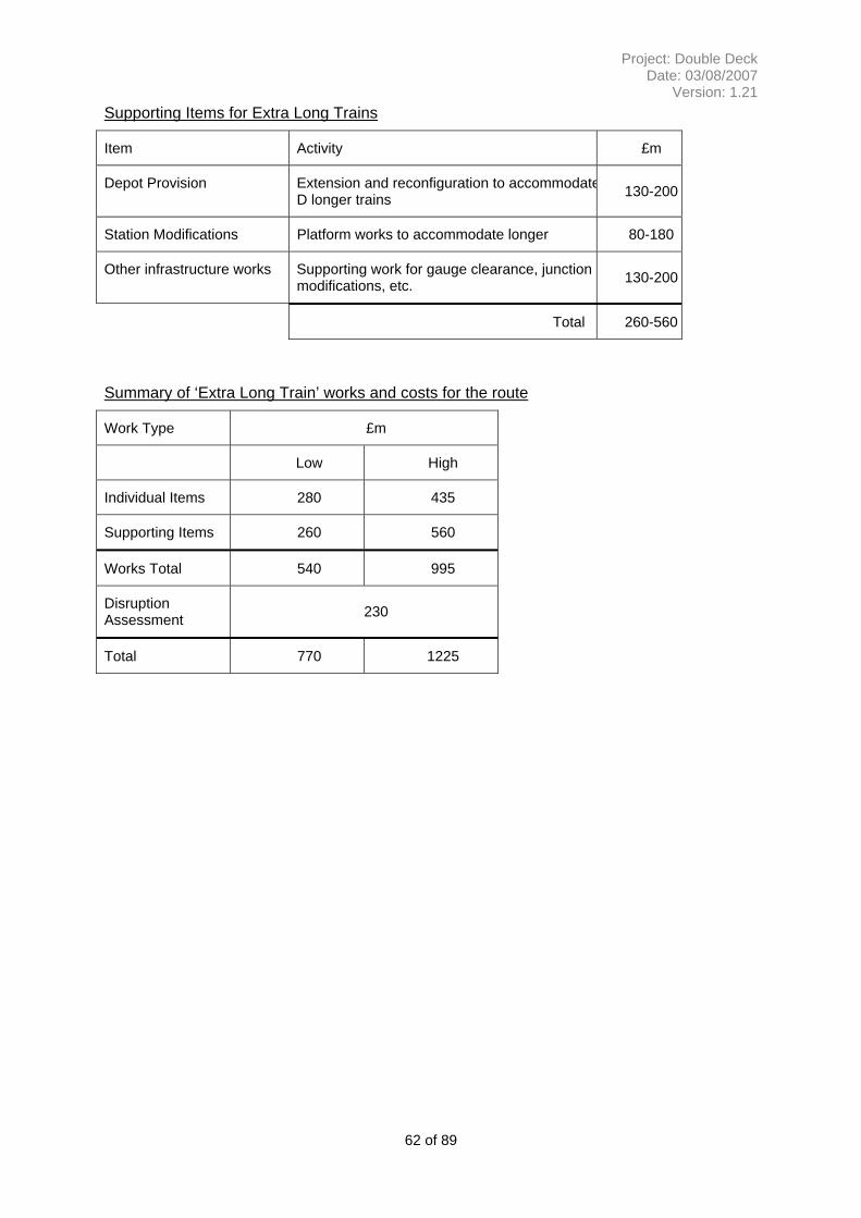
London Victoria/ London Bridge to Brighton
260-560 280-435 540-995 230 (30% of 780) 770-1225
Liverpool St – Colchester and Ipswich
240-360 260-560 500-920 220 (30% of 710) 720-1140
Table 1.4 Summary of infrastructure work activity and comparison costs for the introduction of Long Trains.
1.4 Supporting Issues and Comment
As part of the study, consideration was given to the background of available gauges to both the UK and Continental railways. Whilst not directly used in the evaluation this does give a background understanding as to why the application of Double Deck vehicles is more economical on some railway networks than others. It also validates the conclusion that many of the findings are transferable between UK routes.
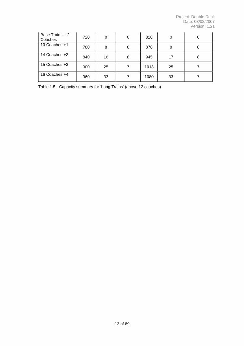
The capacity of longer trains was established by using a 4 car ‘Electrostar’ set as a base vehicle and extension with typical standard class vehicles.
Train
Total Seats LD
% Seats on base
% Seats on increment
Total Seats HD
% Seats on base
% Seats on increment
11 of 89
Project: Double Deck Date: 03/08/2007
Version: 1.21
Base Train – 12 Coaches 720 0 0 810 0 0
13 Coaches +1 780 8 8 878 8 8
14 Coaches +2 840 16 8 945 17 8
15 Coaches +3 900 25 7 1013 25 7
16 Coaches +4 960 33 7 1080 33 7
Table 1.5 Capacity summary for ‘Long Trains’ (above 12 coaches)
12 of 89
Project: Double Deck Date: 03/08/2007
Version: 1.21
2 PURPOSE
Continued growth in demand on the core commuter routes into London could see a doubling in passenger numbers over the next 30 years. This level of increase will be met in the early phases by solutions which are well understood and applied through the Route Utilisation Process (RUS). This approach is expected to meet demand until around 2020. The purpose of this study is to explore the implications of the application of Double Deck vehicles or Extra Long trains to address the continued growth. These two options are amongst a number of possible solutions which include additional trains through improved performance, use of ERTMS to increase route capacity, the use of different rolling stock ‘layouts’ and the possible construction of additional routes.
This study has completed a structured assessment of the opportunities and implications of operating a Double Deck train or Long Trains on a selection of inter-urban routes around London. To achieve this end the following criteria for this element were established:-
• A concept design for a double deck vehicle to address: - passenger capacity, DDA compliance, on train systems and the overall height / length of the vehicles.
• Measure of the additional capacity provided and a comparison with capacity provided by longer trains and double deck trains.
• Implications for station design and station dwell times.
• An infrastructure assessment which uses existing ‘Omnicom’ video surveys, ClearRoute and other existing data sources to establish the extent of clearance works.
• A broad scoping and costing of the identified works based on unit rates and generic solutions to implement
o Double Deck Trains o Very Long (16 car x 20m or equivalent)
The assessments also addressed the relative incremental cost of achieving UIC GB or GB+ and GC vehicle height concurrent with any works (including any additional scope items).
The routes for Double Deck evaluation are (rationale for each is noted):
• London Victoria/ London Bridge to Brighton (Third Rail, Commuter mainline with tunnels operating at near capacity)
• Liverpool St – Colchester initially then onto Ipswich (OHLE commuter line operating at near capacity)
• Paddington to Reading then onto Oxford and Bristol (OHLE and Diesel operation but built to wider track initially)
• London Waterloo to Southampton (Third Rail, Commuter mainline with tunnels)
13 of 89
Project: Double Deck Date: 03/08/2007
Version: 1.21
Outline statements will also be prepared for
• CTRL – London St Pancras to Ashford
For the extra long train evaluation only the first two routes will be used and a current standard stopping pattern assumed for the stations.
• London Victoria/London Bridge to Brighton
Station Stops – Clapham Junction, East Croydon (via both Quarry Line and the Redhill Line) Redhill, Gatwick Airport, Three Bridges and Haywards Heath
Liverpool St – Colchester and Ipswich
Station Stops – Stratford, Romford, Shenfield, Chelmsford, Witham, Marks Tey, Colchester and Manningtree
14 of 89
Project: Double Deck Date: 03/08/2007
Version: 1.21
3 METHODOLOGY
To undertake this concept study in to the alternatives of using Double Deck vehicles or longer trains (12-16 coaches) the first phase established the possible vehicle configurations and then applied these to the selected routes. The route configurations and capabilities were taken from existing sources and the scope and complexity of the work was derived form these records. The cost of works, were established from a range of current projects and allowances made for the expected additional items such as access, contingency and legal permissions (e.g. TWA).
In deriving the ‘UK Double Deck vehicle’ the trade off between vehicle size and the work required to achieve clearance evidence was developed in a series of iterations, firstly by assessing the historic ruling design criteria for the route. These overall findings gave a robust basis to assess between a marginal improvement in capability and a major rebuild of a route. Secondly these assumptions were tested for items which significantly constrained the capacity of the vehicle to confirm the volume of work on the route. Examples of the overarching constraints included curving rules and bogie spacing which impact on the end and mid throw of the vehicle and the height of platforms which constrain both access to and width of a lower passenger deck.
Evaluation of the works was undertaken on a generic basis of typical work scopes rather than site specific detail. This principle was then carried through into the costing process by giving a standard rate to similar work activities. For the larger and more complex items e.g. tunnels and major junction alterations some site specific detail was added in to confirm the validity of the concept design. For some of the works consideration was given to the incremental costs of achieving other outputs. For example the relative incremental cost of achieving UIC GB+ concurrent with any works. The evaluation of work excluded a number of items at this stage, principally timetable analysis and the impact on traction power. The study also did not address issues of station crowding and dispersal issues. Generic assumptions were made for changes to depots and stabling facilities.
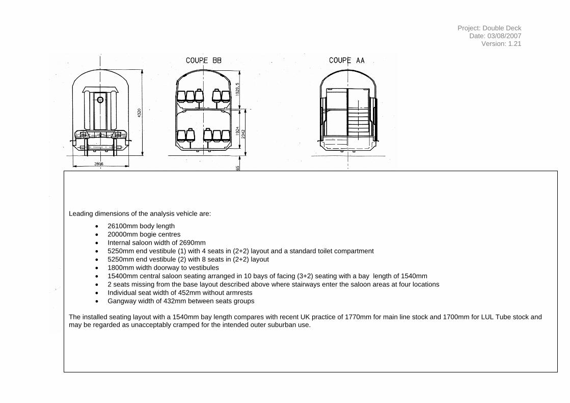
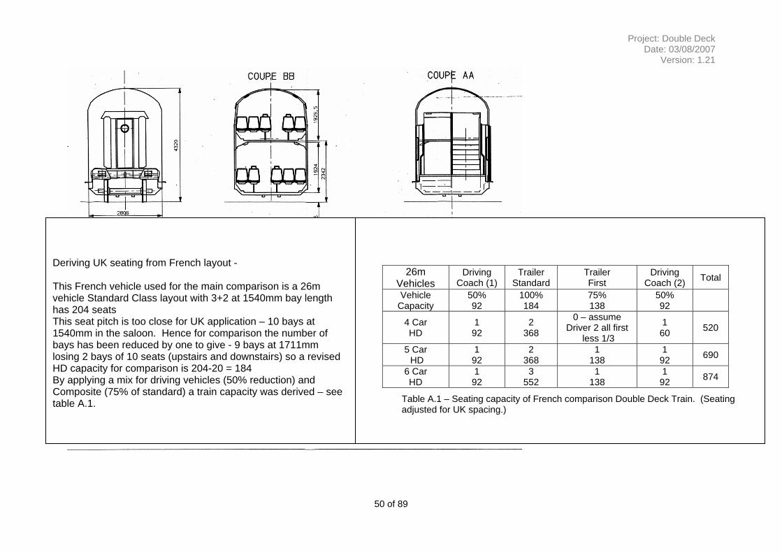
3.1 Characteristics of Double Deck Vehicle
This study uses the experience of the use of double deck trains with other operators to establish a credible vehicle outline and occupancy for UK use. In assessing these existing vehicles the following assumptions were used -
• The service pattern will be for outer suburban operations where the station stops are generally infrequent (compared to inner suburban operations) but with sufficient consideration of stations where peaks of loading occur.
• The general layout and seating density will be comparable with existing outer suburban vehicles although it is anticipated the roof height will be constrained.
• The vehicle will be designed to fit with current platform designs as these trains will need to operate alongside existing rolling stock which will also operate on these routes.
15 of 89
Project: Double Deck Date: 03/08/2007
Version: 1.21
• The issues of flow of people on and off the Platforms will be dealt with by a future assessment. (Consideration will be given to the time required for the reasonable access and egress by the vehicle concept design).
• Vehicle length is not expected to exceed 23m (noted that European vehicles are 26m compared with a historical design limit of 20m stock for the southern routes).
3.2 Concept Design for UK Double Deck Vehicles
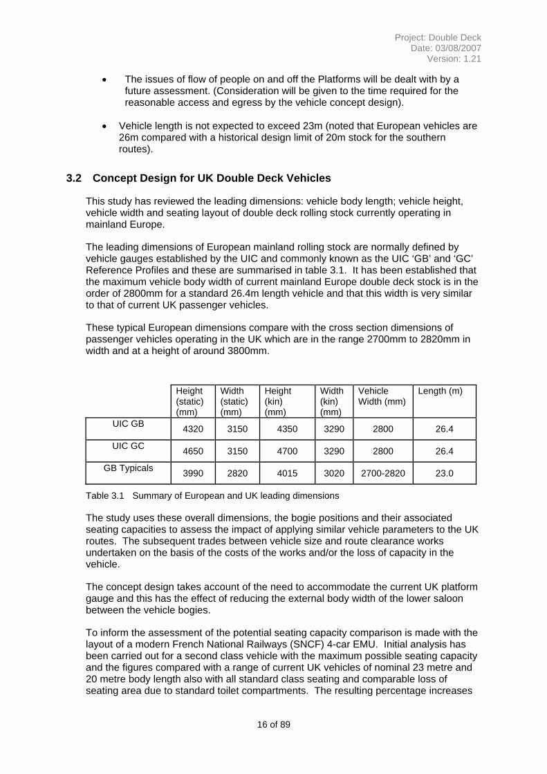
This study has reviewed the leading dimensions: vehicle body length; vehicle height, vehicle width and seating layout of double deck rolling stock currently operating in mainland Europe.
The leading dimensions of European mainland rolling stock are normally defined by vehicle gauges established by the UIC and commonly known as the UIC ‘GB’ and ‘GC’ Reference Profiles and these are summarised in table 3.1. It has been established that the maximum vehicle body width of current mainland Europe double deck stock is in the order of 2800mm for a standard 26.4m length vehicle and that this width is very similar to that of current UK passenger vehicles.
These typical European dimensions compare with the cross section dimensions of passenger vehicles operating in the UK which are in the range 2700mm to 2820mm in width and at a height of around 3800mm.
Height (static) (mm)
Width (static) (mm)
Height (kin) (mm)
Width (kin) (mm)
Vehicle Width (mm)
Length (m)
UIC GB 4320 3150 4350 3290 2800 26.4
UIC GC 4650 3150 4700 3290 2800 26.4
GB Typicals 3990 2820 4015 3020 2700-2820 23.0
Table 3.1 Summary of European and UK leading dimensions
The study uses these overall dimensions, the bogie positions and their associated seating capacities to assess the impact of applying similar vehicle parameters to the UK routes. The subsequent trades between vehicle size and route clearance works undertaken on the basis of the costs of the works and/or the loss of capacity in the vehicle.
The concept design takes account of the need to accommodate the current UK platform gauge and this has the effect of reducing the external body width of the lower saloon between the vehicle bogies.
To inform the assessment of the potential seating capacity comparison is made with the layout of a modern French National Railways (SNCF) 4-car EMU. Initial analysis has been carried out for a second class vehicle with the maximum possible seating capacity and the figures compared with a range of current UK vehicles of nominal 23 metre and 20 metre body length also with all standard class seating and comparable loss of seating area due to standard toilet compartments. The resulting percentage increases
16 of 89
Project: Double Deck Date: 03/08/2007
Version: 1.21
in seating capacity can be regarded as maxima for the trailer vehicle. This reference vehicle also featured a low floor height which is a necessary feature of the UK vehicle. To achieve this there is a generous allowance for above floor equipment in the end vehicles. For the purposes of this study these have been reflected in the proposed train and a opportunity recorded for improving the arrangements for the traction equipment.
The estimation of the potential seating capacity of a UK profile double deck vehicle for nominal 23 metre and 20 metre body lengths is thereby determined for both high density (3+2) and low density (2+2) seating layouts in the upper saloon and for a similar seat bay length to current UK practice.
To extrapolate the seating capacity of a single vehicle to that of a train allowances were made for a reduced density of seating in first class accommodation, wheelchair space, provision for disabled toilet facilities and space provision for electrical and auxiliary equipment that would primarily be mounted below saloon floor level in conventional EMU stock. Figures have been assessed based on a comparison of the relative seating capacities of the all-second class vehicle with that of the Driving Coach and composite coach of the French Railways EMU ‘analysis’ vehicles. The provision for standing passengers was derived from the current standards on vehicle loading and the franchise targets for an acceptable level of standing on a day to day basis.
Appendix K of this report examines the background to the development of mainland Europe vehicle gauges, describes the UIC ‘GB’ and ‘GC’ Reference Profiles and relates the reference profiles to actual vehicle body lengths and widths that are in current operation.
3.3 Extra Long Train Operation
The evaluation of extra long trains focused on the testing of the physical fit of 16 car trains on the routes. Where, it is accepted that an incremental approach would demonstrate the marginal benefits of each stage but this will be a refinement of the study. The assumptions and start points used for the longer trains are -
• The additional vehicles will fit to the existing infrastructure in terms of gauge, speed, acceleration, braking and compatibility with existing rolling stock.
• Issues of station design and station dwell times will be covered by a future investigation.
• Issues of junction occupancy and clearance times will be addressed by a future timetable study.
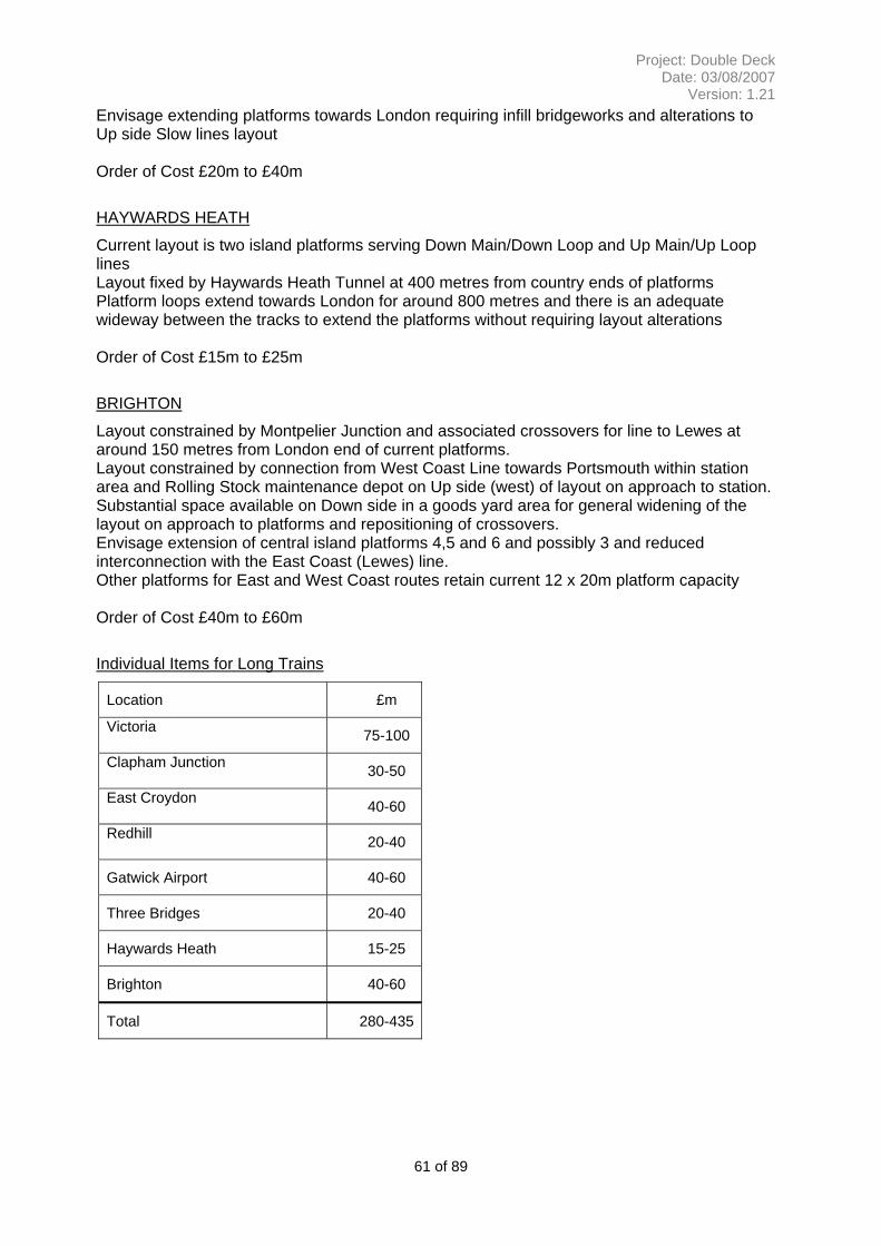
The passenger capacity of extra long trains has been determined based on 16 car x nominal 20 metre vehicle formations requiring an extension of existing 12 car platforms by around 85 metres.
An assessment of the requirements for provision of extended platforms has been made for the terminal and principal stopping points on the selected routes to determine physical space and the extent of changes to track layout and signalling. Order of magnitude costing for physical works have been determined for the assessed changes to infrastructure.
17 of 89
Project: Double Deck Date: 03/08/2007
Version: 1.21
3.4 Evaluation of Work Scope
Evaluation of the works was undertaken on a generic basis of blocks of scope rather than site specific detail. Need for the work was derived from a number of existing sources and an analysis of current and historical standards. Where appropriate the opportunity to achieve further capability improvement at marginal cost was explored e.g. the incremental cost of achieving UIC GB+.
The evaluation of work excluded a number of items at this stage, principally timetable analysis and the impact on traction power. The study also did not address issues of station crowding and dispersal issues. Generic assumptions were made for changes to depots and stabling facilities.
To establish current route capability the following resources were used -
• ‘Omnicom’ route video to identify all over line structures and other railway infrastructure that could be foul of rolling stock of greater height than for current operations Omnicom’ video surveys.
• The Network Rail National Gauging Database has been used to obtain the current height from rail level to underside of the bridge and profile of the deck or arch.
• Ordnance Survey mapping has been used to assess the surrounding area at each over line structure to identify urban, residential and rural conditions.
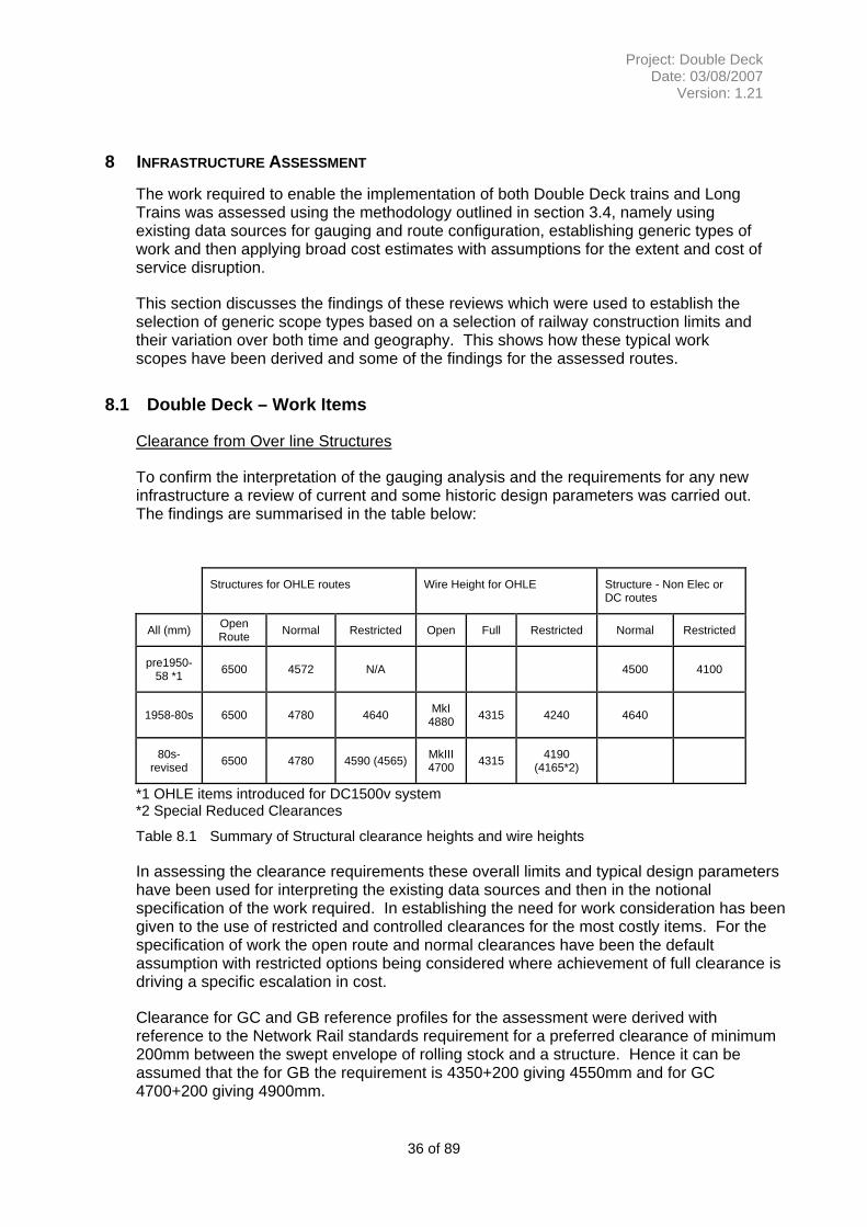
Based on the UIC ‘GB’ or ‘GC’ Reference Profile height of 4350mm and 4700mm above rail level respectively plus an allowance of 200mm for gauge clearance, any requirement for raising of the bridge deck, reconstruction of the bridge deck or the potential for track lowering has been identified.
The complexity of any work to raise the height of the bridge and the consequential effect on the surrounding area at road level together with the likelihood of there being significant gas, water, drainage, power and telecommunications routes at road level has been assessed.
The study considers the incremental cost of enhancing the loading gauge to support UIC GB+ and UIC GC operation so as to understand the incremental costs of going to a further enlarged gauge (with implications for passenger acceptability).
For all activities an assessment of the likely disruption to services (in terms of physical extent and duration) has been made.
To confirm assumptions and generic scope two pieces of background work are included firstly, Appendix M describes the development of vehicle and structure gauges in the UK and the dimensional relationship between Overhead Line electrification equipment and over line structures in order to identify expectations for the extent of infrastructure works. Secondly Appendix J describes the dimensional relationship of overhead line equipment to over line structures.
3.5 Costing of Work
Potential works have been allocated against a five point scale to reflect the complexity of the works and disruption to railway business and the local area with a broad order of
18 of 89
Project: Double Deck Date: 03/08/2007
Version: 1.21
cost determined for each category. This will give an approximate cost for the introduction of a double deck train on each route, along with a commentary on key issues to be addressed, scale and timings for any disruptions.
In drawing together a total number allowances have been added for depot works and other significant infrastructure items. Then an overall project management percentage has been used. In this case 15% was selected in recognition of the overall complexity of either solution. A broad contingency of -50 / +100% is applied to reflect the range of possible scope solutions. An allowance for disruption is then applied to the range in recognition of how the evaluation and treatment of disruption can vary over time.
In assessing disruption an overall figure of 30% was used for most works. Where specific and extensive disruption would occur (e.g. protracted route closure) then additional lump sums were included (circa £10m per item) by revising the percentage.
19 of 89
Project: Double Deck Date: 03/08/2007
Version: 1.21
4 FINDINGS – CONCEPT DESIGN FOR DOUBLE DECK VEHICLES
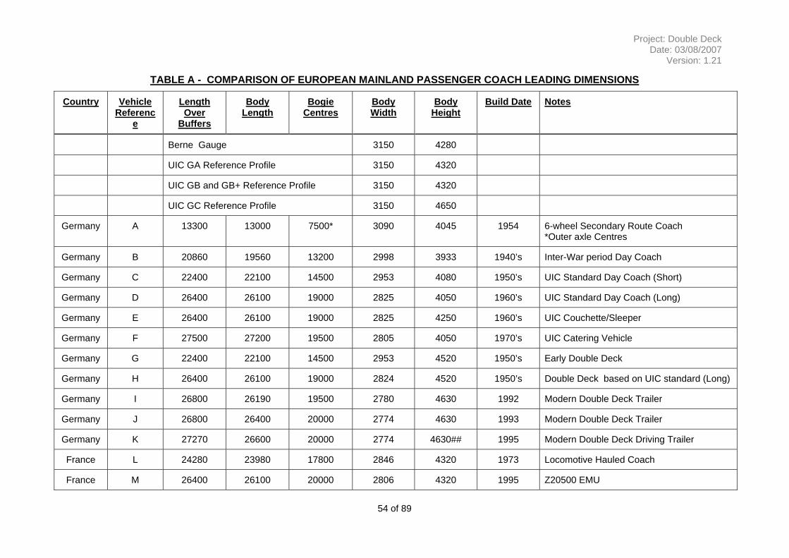
4.1 Key features of European mainland double deck rolling stock
Around thirteen examples of European Double Deck rolling stock were compared to understand the trends in development and the variations in application and the specific gauge characteristics of the host nation.
The discussion and base information used is located in –
• Appendix K which examines the background to the development of mainland Europe vehicle gauges, describes the UIC ‘GB’ and ‘GC’ Reference Profiles and relates the reference profiles to actual vehicle body lengths and widths that are in current operation.
• Appendix C examines the detailed sizing of mainland European rolling stock to allow comparison with the UK vehicle gauge width.
• Appendix L describes the application, to date, of the UIC Reference profiles in the UK
The conclusions of this review are summarised below –
• Double deck rolling stock operated by the principal European mainland railways on conventional rather than high speed routes are based on three principal vehicle layouts
o Intermediate trailer vehicles with two sets of 1800mm wide doorways per side positioned over the bogies and serving a vestibule area with the floor level at around 1150mm above rail level.
o Driving trailer vehicles or EMU driving coaches with two sets of 1800mm wide doorways per side positioned inboard of the bogies and serving a vestibule area with a floor level at around 600mm above rail level.
o French Railways EMU vehicles with three sets of doorways per side serving vestibule areas with a floor level at around 1000mm above rail level optimised for high volume suburban services with limited station dwell time.
o For the intermediate trailer design, stairways run from each vestibule area to the lower saloon requiring 3 or 4 steps and to the upper saloon requiring 7 steps.
• A short ramp or single step connects the vestibules of the driving coach design to the lower saloon and a 3 or 4 steps link to a small saloon area positioned over the bogies with a further similar flight from the bogie area saloon to the upper saloon.
• To minimise the footprint of the stairways, the riser and going dimensions provide a steeper than average stair design than is normally applied to areas with public access.
• Allowing for the inter vehicle gangway, the vestibule area has sufficient space for a standard toilet compartment or a group of facing seating on each side of the
20 of 89
Project: Double Deck Date: 03/08/2007
Version: 1.21
gangway. Provision for a larger disabled toilet compartment requires a reduction of the seating saloon areas and is usually placed in the driving vehicle.
For comparison, Appendix B shows the layout of German National Railways intermediate coach and driving trailer vehicles with a lower density seating layout.
Doorways of both vehicle types have an 1800mm clear width that compares with a maximum 1300mm doorway used in current UK vehicles. The larger door would be required in a UK double deck application to minimise station dwell time.
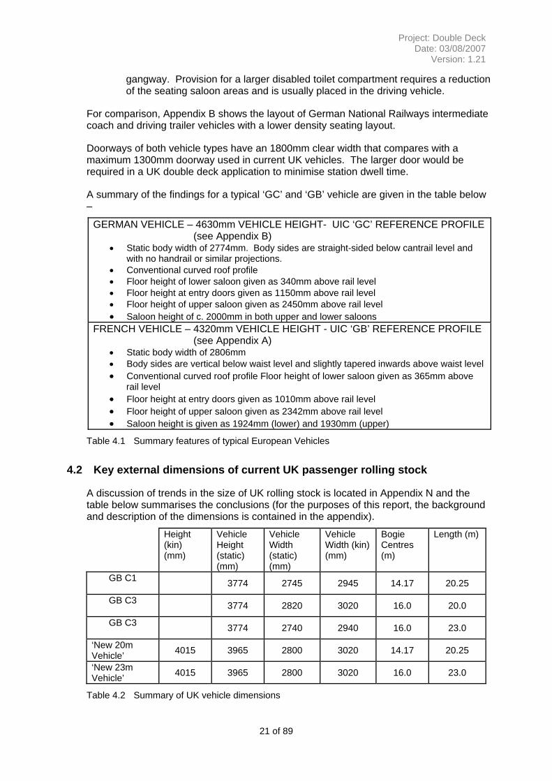
A summary of the findings for a typical ‘GC’ and ‘GB’ vehicle are given in the table below –
GERMAN VEHICLE – 4630mm VEHICLE HEIGHT- UIC ‘GC’ REFERENCE PROFILE (see Appendix B)
• Static body width of 2774mm. Body sides are straight-sided below cantrail level and with no handrail or similar projections.
• Conventional curved roof profile • Floor height of lower saloon given as 340mm above rail level • Floor height at entry doors given as 1150mm above rail level • Floor height of upper saloon given as 2450mm above rail level • Saloon height of c. 2000mm in both upper and lower saloons
FRENCH VEHICLE – 4320mm VEHICLE HEIGHT - UIC ‘GB’ REFERENCE PROFILE (see Appendix A)
• Static body width of 2806mm • Body sides are vertical below waist level and slightly tapered inwards above waist level • Conventional curved roof profile Floor height of lower saloon given as 365mm above
rail level • Floor height at entry doors given as 1010mm above rail level • Floor height of upper saloon given as 2342mm above rail level • Saloon height is given as 1924mm (lower) and 1930mm (upper)
Table 4.1 Summary features of typical European Vehicles
4.2 Key external dimensions of current UK passenger rolling stock
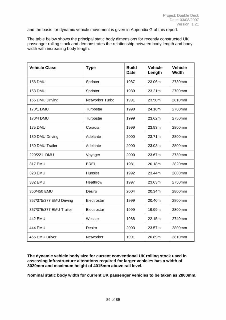
A discussion of trends in the size of UK rolling stock is located in Appendix N and the table below summarises the conclusions (for the purposes of this report, the background and description of the dimensions is contained in the appendix).
Height (kin) (mm)
Vehicle Height (static) (mm)
Vehicle Width (static) (mm)
Vehicle Width (kin) (mm)
Bogie Centres (m)
Length (m)
GB C1 3774 2745 2945 14.17 20.25
GB C3 3774 2820 3020 16.0 20.0
GB C3 3774 2740 2940 16.0 23.0
‘New 20m Vehicle’ 4015 3965 2800 3020 14.17 20.25
‘New 23m Vehicle’ 4015 3965 2800 3020 16.0 23.0
Table 4.2 Summary of UK vehicle dimensions
21 of 89
Project: Double Deck Date: 03/08/2007
Version: 1.21
The two ‘new vehicle’ dimensions were therefore used as a basis for developing the shell of the ‘UK Double Deck Vehicle’. Whilst height is the obvious constraint the loss of vehicle length and the relatively tight bogie centres, compared to the European vehicles cause significant constraints on the capacity of a double deck vehicle. Consideration was given to extending the length of the vehicles and whilst this would generate some advantage this is limited by the constraint on the lower deck from the bogie positions. Also increasing length on some of the southern suburban routes would lead to extensive infrastructure changes given the ruling ‘20m’ design of the infrastructure. Similar consideration was given to moving the bogie centres, but this again would lead to a wholesale reconfiguration of the railway especially on the tighter curves and through features such as stations on curves. For example the wholesale re-alignment and re-construction of Clapham Junction. The study also showed that for some of the southern routes longer vehicles could be deployed in which case benefits similar to the 23m vehicle could be gained. This study did not seek to confirm this for any particular route but the London – Brighton is considered the most likely and the South Eastern the more restrictive.
4.3 Key internal dimensions and layout of current UK passenger rolling stock
The layout of current inter-urban rolling stock in the UK has the following characteristics:
• Double sliding or plug door openings at approximately one-third and two-third positions over the body length.
• Maximum 1300mm clear door openings.
• Vehicle floor height of around 1150mm above rail level.
• The length of facing seating bays vary between 1770mm and 1830mm for standard seating plus an additional 100mm for designated priority seating.
• Pitch length for airline layout seating varies between 760mm and 830mm for standard seating plus an additional 100mm for designated priority seating.
• Internal saloon width of 2650mm for the typical 2800mm maximum external body width as identified above.
• Standard Class seating is arranged in a ‘low density’ (2+2) format with armrests or ‘high density’ (3+2) format without armrests and in some cases with a combination of both types within a train set.
• First Class seating is arranged in either a (2+2) or (2+1) format always with armrests.
• Individual seats HD min 455mm no armrests, LD same with 60mm armrests.
For the purposes of this study the layout of the ‘Electrostar’ stock will be used as a base for comparison and population of the vehicle shell.
22 of 89
Project: Double Deck Date: 03/08/2007
Version: 1.21
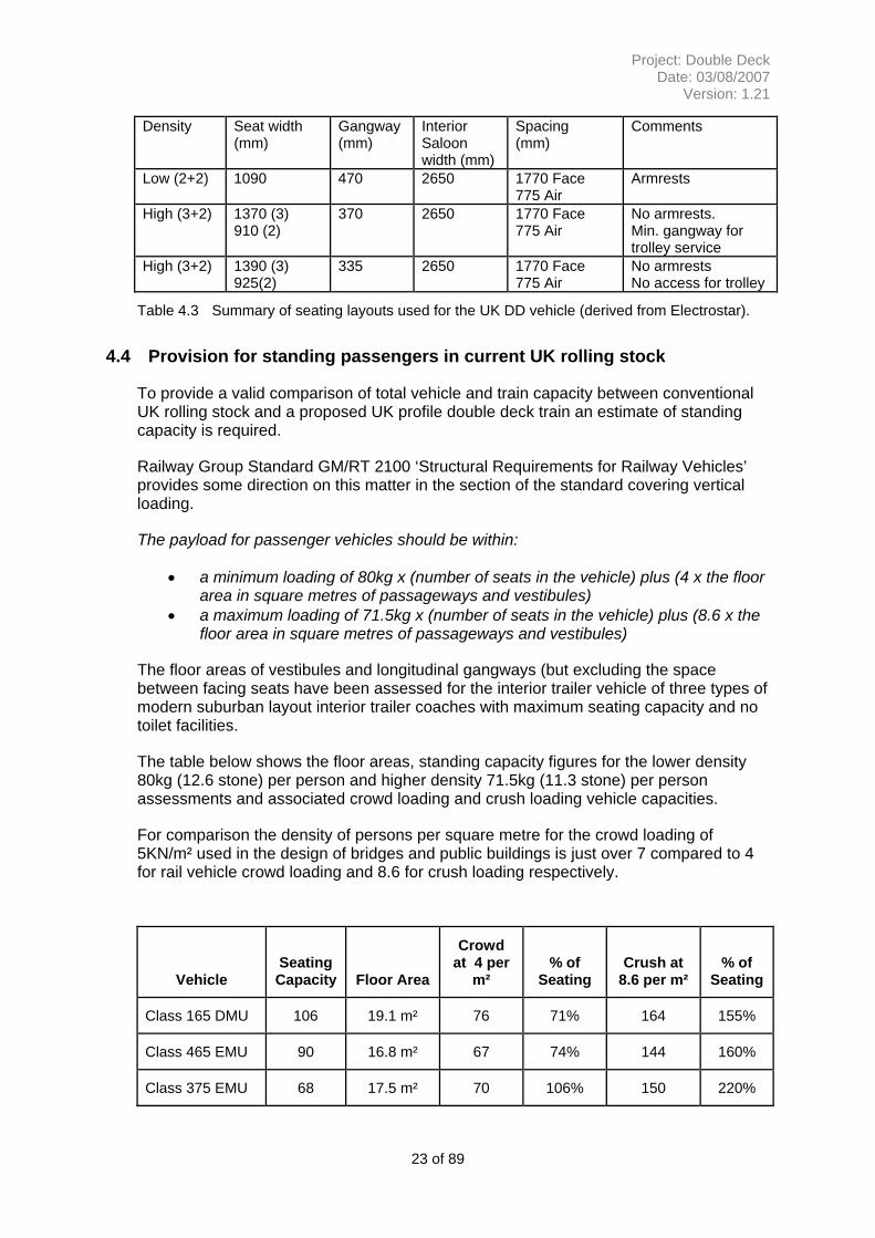
Density Seat width (mm)
Gangway (mm)
Interior Saloon width (mm)
Spacing (mm)
Comments
Low (2+2) 1090 470 2650 1770 Face 775 Air
Armrests
High (3+2) 1370 (3) 910 (2)
370 2650 1770 Face 775 Air
No armrests. Min. gangway for trolley service
High (3+2) 1390 (3) 925(2)
335 2650 1770 Face 775 Air
No armrests No access for trolley
Table 4.3 Summary of seating layouts used for the UK DD vehicle (derived from Electrostar).
4.4 Provision for standing passengers in current UK rolling stock
To provide a valid comparison of total vehicle and train capacity between conventional UK rolling stock and a proposed UK profile double deck train an estimate of standing capacity is required.
Railway Group Standard GM/RT 2100 ‘Structural Requirements for Railway Vehicles’ provides some direction on this matter in the section of the standard covering vertical loading.
The payload for passenger vehicles should be within:
• a minimum loading of 80kg x (number of seats in the vehicle) plus (4 x the floor area in square metres of passageways and vestibules)
• a maximum loading of 71.5kg x (number of seats in the vehicle) plus (8.6 x the floor area in square metres of passageways and vestibules)
The floor areas of vestibules and longitudinal gangways (but excluding the space between facing seats have been assessed for the interior trailer vehicle of three types of modern suburban layout interior trailer coaches with maximum seating capacity and no toilet facilities.
The table below shows the floor areas, standing capacity figures for the lower density 80kg (12.6 stone) per person and higher density 71.5kg (11.3 stone) per person assessments and associated crowd loading and crush loading vehicle capacities.
For comparison the density of persons per square metre for the crowd loading of 5KN/m² used in the design of bridges and public buildings is just over 7 compared to 4 for rail vehicle crowd loading and 8.6 for crush loading respectively.
Vehicle Seating Capacity Floor Area
Crowd at 4 per
m² % of
Seating Crush at
8.6 per m² % of
Seating
Class 165 DMU 106 19.1 m² 76 71% 164 155%
Class 465 EMU 90 16.8 m² 67 74% 144 160%
Class 375 EMU 68 17.5 m² 70 106% 150 220%
23 of 89
Project: Double Deck Date: 03/08/2007
Version: 1.21
Table 4.4 Evaluation of crowding capacity in current rolling stock.
Based on these sample results it is proposed that an average standing capacity of 75% of the seated capacity is adopted in overall train capacity determinations within this report.
This analysis provides the comparison figure for a technical crowded level carrying capacity. In terms of service provision it is expected that the current commercial targets of no standing for journeys over 20minutes and no more than around 30% standing for shorter journeys are likely to apply.
4.5 Concept Design for UK Profile Double Deck Vehicle
The analysis of European and UK practice has been drawn to together to produce the concept design for a UK profile vehicle and then extrapolated into a train formation. In drawing the analyses together the following have been addressed and are discussed in the following sections:
• Acceptable height of each saloon
• Achievable width of each saloon
• Seating capability of each saloon
• Seating layout of each saloon for each vehicle length
• Reprise of the arguments for a 26m vehicle
• Reprise of the arguments for using a ‘standard European vehicle
The concept design study for a UK profile double deck vehicle has examined passenger vehicle lengths in current use in the UK and, as concluded in section 4.2, will use the following dimensions for the overall shell –
Height (kin) (mm)
Vehicle Height (static) (mm)
Vehicle Width (static) (mm)
Vehicle Width (kin) (mm)
Bogie Centres (m)
Length (m)
‘New 20m Vehicle’
4350(GB) 4700(GC)
4320(GB) 4650(GC) 2800 3020 14.17 20.25
‘New 23m Vehicle’
4350(GB) 4700(GC)
4320(GB) 4650(GC) 2740 2960 16.0 23.0
Table 4.5 Assumed vehicle dimensions for Double Deck vehicle (see appendix D)
Height of Vehicle
To derive an acceptable saloon height comparison was made between heights achieved in the two European vehicles namely 2000mm, 1924mm and 1930mm and those experienced on other transport modes as a qualitative measure. From this a minimum value of 1920mm was chosen, this is similar to the London Underground tube stock (e.g. the Victoria Line) but taller than the top deck of a double deck bus. This assessment also aligns with the overall objective of providing an improved passenger environment by providing for a population that is taller than it has been historically and
24 of 89
Project: Double Deck Date: 03/08/2007
Version: 1.21
forecast to have an increasing body mass index. From the 1920mm cabin provision a vehicle size of 4320mm was derived which then gave a vehicle requiring GB clearance as a minimum. For the purposes of the study a GC vehicle was evaluated to understand the cost premium of providing further improvement in height and the possible benefit of a improved gauge for freight use. This gave a vehicle height of 4650mm and a cabin height of 2030mm. (If a GC vehicle was fully engineered then it is expected that the cabin heights would reduce to provide more under-floor space for equipment etc.) Appendix D shows the derivation and allowances in establishing the heights and an indicative cross section of the vehicle.
Width of Lower Passenger Saloon
The potential width of the lower passenger saloon has been assessed from consideration of the ‘lower sector’ structure gauge that is applicable up to 1100mm above rail level and is defined in Railway Group Standard GC/RT 5212. Adherence to an acceptable limit on width is necessary to avoid ‘low’ structures such as bridge beams and shunt signals.
Conventional passenger vehicles have operational equipment mounted beneath the coach body having a typical maximum width of around 2180mm for exposed equipment. For those with enclosed equipment the maximum width just beneath the underside of the vehicle body is around 2300mm with an angled profile reducing to 1920mm at the bottom corner at 250mm above rail level.
Records show that a two level car transporting van with a rectangular cross section lower deck area between bogies at 13.25m centres had an external body width of 2275mm.
The ‘upper sector’ body width for 23m vehicles is 80mm less than the body width for a vehicle with full C3 profile of 2820mm and this reduction can be deemed to also apply to the lower sector area.
Research into the derivation of the lower sector gauge width suggests that there is some degree of conservatism in the assessment of the controlling dimensions and that a detailed gauging study applying minimum clearances may permit an increased saloon width.
Based on the above a maximum external width of a lower saloon is assessed as 2300mm for a nominal 20 metre vehicle length and 2250mm for a 23 metre vehicle
Layout of Lower Passenger Saloon
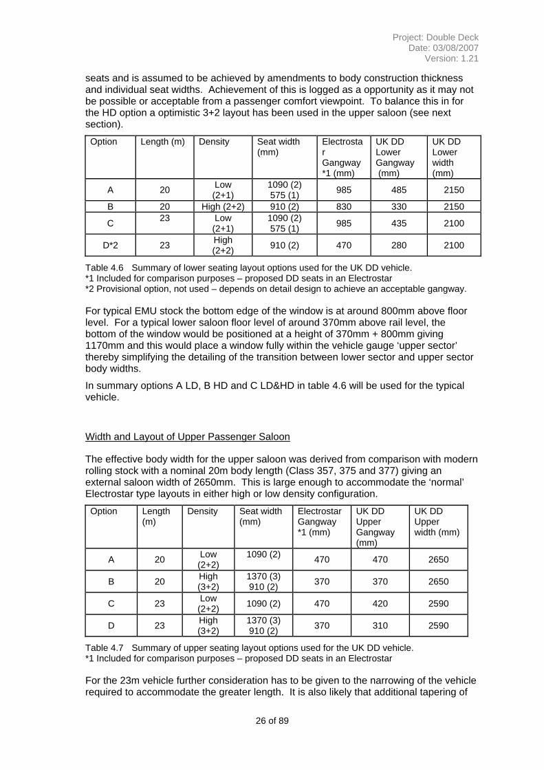
For an external width body of 2300mm and allowing 75mm for thickness of body construction, the interior saloon width would be 2150mm. This compares with 2650mm in the Electrostar vehicle. A range of seating options was considered and summarised in table 4.6.
For the lower saloon in the 20m vehicle the 2+2 formation (B) is acceptable with a minimum gangway provision of 330mm (compared to 335mm in the most compact Electrostar layout),
The assessment of the lower saloon width for a 23m vehicle is 50mm narrower than for 20m vehicles. Applied directly, as shown in the table, this makes the gangway unacceptable. However, a potential seating option for a HD seating with an additional 6 seats could be used. This contrasts with a full 2+2 seating layout which would give 14
25 of 89
Project: Double Deck Date: 03/08/2007
Version: 1.21
seats and is assumed to be achieved by amendments to body construction thickness and individual seat widths. Achievement of this is logged as a opportunity as it may not be possible or acceptable from a passenger comfort viewpoint. To balance this in for the HD option a optimistic 3+2 layout has been used in the upper saloon (see next section).
Option Length (m) Density Seat width (mm)
Electrostar Gangway *1 (mm)
UK DD Lower Gangway (mm)
UK DD Lower width (mm)
A 20 Low (2+1)
1090 (2) 575 (1) 985 485 2150
B 20 High (2+2) 910 (2) 830 330 2150
C 23
Low (2+1)
1090 (2) 575 (1) 985 435 2100
D*2 23 High (2+2) 910 (2) 470 280 2100
Table 4.6 Summary of lower seating layout options used for the UK DD vehicle. *1 Included for comparison purposes – proposed DD seats in an Electrostar *2 Provisional option, not used – depends on detail design to achieve an acceptable gangway.
For typical EMU stock the bottom edge of the window is at around 800mm above floor level. For a typical lower saloon floor level of around 370mm above rail level, the bottom of the window would be positioned at a height of 370mm + 800mm giving 1170mm and this would place a window fully within the vehicle gauge ‘upper sector’ thereby simplifying the detailing of the transition between lower sector and upper sector body widths.
In summary options A LD, B HD and C LD&HD in table 4.6 will be used for the typical vehicle.
Width and Layout of Upper Passenger Saloon
The effective body width for the upper saloon was derived from comparison with modern rolling stock with a nominal 20m body length (Class 357, 375 and 377) giving an external saloon width of 2650mm. This is large enough to accommodate the ‘normal’ Electrostar type layouts in either high or low density configuration.
Option Length (m)
Density Seat width (mm)
Electrostar Gangway *1 (mm)
UK DD Upper Gangway (mm)
UK DD Upper width (mm)
A 20 Low (2+2)
1090 (2) 470 470 2650
B 20 High (3+2)
1370 (3) 910 (2) 370 370 2650
C 23 Low (2+2) 1090 (2) 470 420 2590
D 23 High (3+2)
1370 (3) 910 (2) 370 310 2590
Table 4.7 Summary of upper seating layout options used for the UK DD vehicle. *1 Included for comparison purposes – proposed DD seats in an Electrostar
For the 23m vehicle further consideration has to be given to the narrowing of the vehicle required to accommodate the greater length. It is also likely that additional tapering of
26 of 89
Project: Double Deck Date: 03/08/2007
Version: 1.21
the body side will be necessary and the further chamfering of the body ends. In summary it is assumed that the 3+2 high density layout will become constrained. However, this option (D) has been adopted to give a balance to the risks and opportunities for HD seating arrangements in the longer, but narrower 23m vehicle.
In summary the two options A and D will be used to evaluate the typical vehicle whilst noting that a high density configuration could be used for shorter journeys.
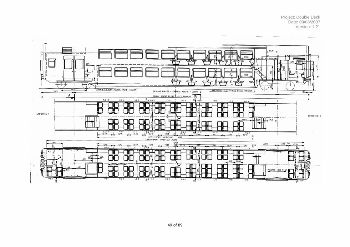
Review of nominal 26m length vehicle
The study has also considered a nominal 26 metre length vehicle that is the standard body size for European coaching stock.
The French Railways EMU intermediate trailer vehicle used for analysis of seating capacity has a 26.1m length body and 20.0m bogie centres that maximises the space available in the lower passenger saloon area.
The length of the central passenger saloon area is 15400mm and that of the vehicle end sections incorporating the entrance/exit vestibule, stairways to the passenger saloons, standard toilet, end gangways to adjacent coach and some seating is 5450mm.
The Intercity Express Programme (IEP) has examined the gauging of 26m vehicles adapted for operation on current UK infrastructure with a kinematic envelope no greater than that for a current nominal 23m vehicle.
It has been determined that the vehicles would have to be proportioned with 17 metre rather than the normal maximum 20 metre bogie centres used on modern European double deck vehicles to allow for end and centre throw restrictions on curved track imposed by the current infrastructure.
The effect of this would be to reduce the length of the central passenger saloon area from 15400mm to 12400mm with consequential loss of two seating bays per saloon and increase the length of the end sections by 1.5m each with some additional seating provided.
The initial gauging study has also determined that a tapering body profile may be required over a length of around 2 metres at body ends to match the 23m vehicle gauging profile and the consequential narrowing of the saloon width could also require the removal of some seating to retain an adequate gangway width.
The consequential reduction in the length of the lower saloon between the bogies has a significant effect on the potential seating capacity.
An analysis of the seating capacity for a 26m vehicle layout as described is included below showing a marginal increase in capacity of eight seats over the 23m vehicle. All the additional seating is in the vestibule which is not ideal for the duration of outer suburban trips.
Given this marginal increase in seating, the vestibule location and the significant cost implications for accommodating the longer vehicle the study focused on the 23m option.
27 of 89
Project: Double Deck Date: 03/08/2007
Version: 1.21
26m Vehicle Lower Saloon Bays @ 1750mm
Upper Saloon Bays @ 1750mm
Stairway Reduction Vestibule
Total Seats
Total Seats 23m
High Density 7(2+2) 56
7 (2+2) 56 8 20 124 116
Low Density 7(2+1) 42
7 (2+2) 56 8 20 110 102
Table 4.8 Comparison of seating capacity between 23m and 26m vehicles *1 Assume an increase in the length of the end vestibules of 1500mm each allowing two additional rows of airline seating in (2+2) layout per vestibule.
(Note: for a complete description of the vehicle seating calculations see section 5.)
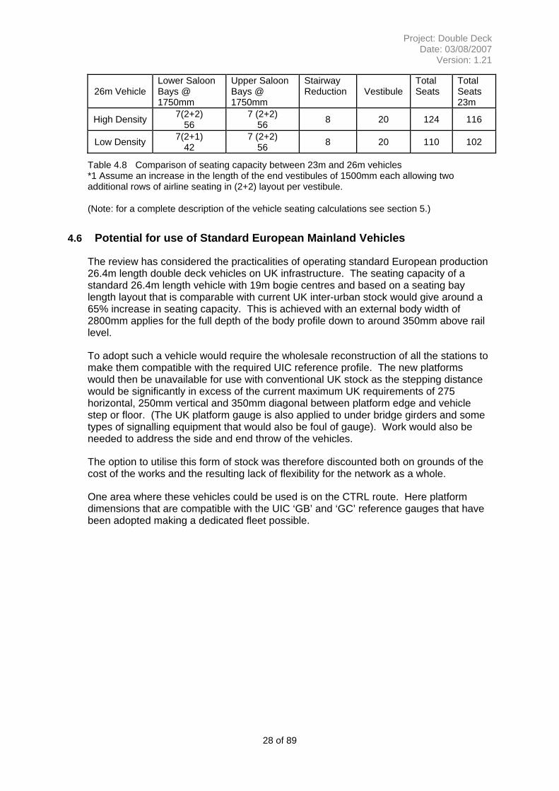
4.6 Potential for use of Standard European Mainland Vehicles
The review has considered the practicalities of operating standard European production 26.4m length double deck vehicles on UK infrastructure. The seating capacity of a standard 26.4m length vehicle with 19m bogie centres and based on a seating bay length layout that is comparable with current UK inter-urban stock would give around a 65% increase in seating capacity. This is achieved with an external body width of 2800mm applies for the full depth of the body profile down to around 350mm above rail level.
To adopt such a vehicle would require the wholesale reconstruction of all the stations to make them compatible with the required UIC reference profile. The new platforms would then be unavailable for use with conventional UK stock as the stepping distance would be significantly in excess of the current maximum UK requirements of 275 horizontal, 250mm vertical and 350mm diagonal between platform edge and vehicle step or floor. (The UK platform gauge is also applied to under bridge girders and some types of signalling equipment that would also be foul of gauge). Work would also be needed to address the side and end throw of the vehicles.
The option to utilise this form of stock was therefore discounted both on grounds of the cost of the works and the resulting lack of flexibility for the network as a whole.
One area where these vehicles could be used is on the CTRL route. Here platform dimensions that are compatible with the UIC ‘GB’ and ‘GC’ reference gauges that have been adopted making a dedicated fleet possible.
28 of 89
Project: Double Deck Date: 03/08/2007
Version: 1.21
5 ESTIMATE OF SEATING CAPACITY OF UK PROFILE DOUBLE DECK VEHICLES
5.1 Base Analysis vehicle
To estimate the potential seating capacity for a UK profile double deck vehicle can be made by comparison with the intermediate Second class trailer of the French Railways Class Z20500 EMU illustrated, along with its leading dimensions in Appendix A. The sizing of the vestibules, saloons and doorways were assessed and proportioned back to the proposed dimensions of the UK vehicles. Allowances were also made for the tighter seat spacing used in the French vehicle (i.e. expanded to a typical spacing for UK application). The estimates were made by varying the seating pitch and layout of the centre saloons whilst retaining the layout of the entrance vestibules and stairways to the passenger saloons. The analysis has been conducted on the standard class layout and the results compared with current UK vehicles of similar format. (With seat bay lengths in the range 1700mm to1800mm determined to ‘fit’ the shorter ‘UK’ saloon lengths).
5.2 Analysis of the 23m vehicle
For a nominal 23m vehicle with 16m bogie centres by reduction of the central saloon length of the analysis vehicle by the difference in bogie centres of 4000mm giving an 11400mm saloon. Bay length of 6 would be too short and 7 too long. So with an assumed vestibule end reduction of 425mm this gives 7 bays at 1750mm bay lengths. The previously derived bay widths, gives the seating per bay.
For a nominal 20m vehicle with 14.17m bogie centres by reduction of the central saloon length of the analysis vehicle by the difference in bogie centres of 5830mm giving a 9570mm saloon. Bay length of 5 would be too short and 6 too long. In this case the required adaptation of the vestibule would be too great so a bay layout with an airline arrangement for the balance is used. This gives 5 ½ bays at 1750mm bay lengths. The previously derived bay widths, gives the seating per bay.
29 of 89
Project: Double Deck Date: 03/08/2007
Version: 1.21
20m Vehicle Lower Saloon Bays @ 1750mm
Upper Saloon Bays @ 1750mm
Stairway Reduction Vestibule
Total Seats
High Density 5.5(2+2) 44
5.5 (3+2) 55 8 12 103
High Density *1
5.5(2+1) 33
5.5 (3+2) 55 8 12 92
Low Density 5.5(2+1) 33
5.5 (2+2) 44 8 12 81
*1 Included to illustrate the effect of not achieving an acceptable width to the lower saloon.
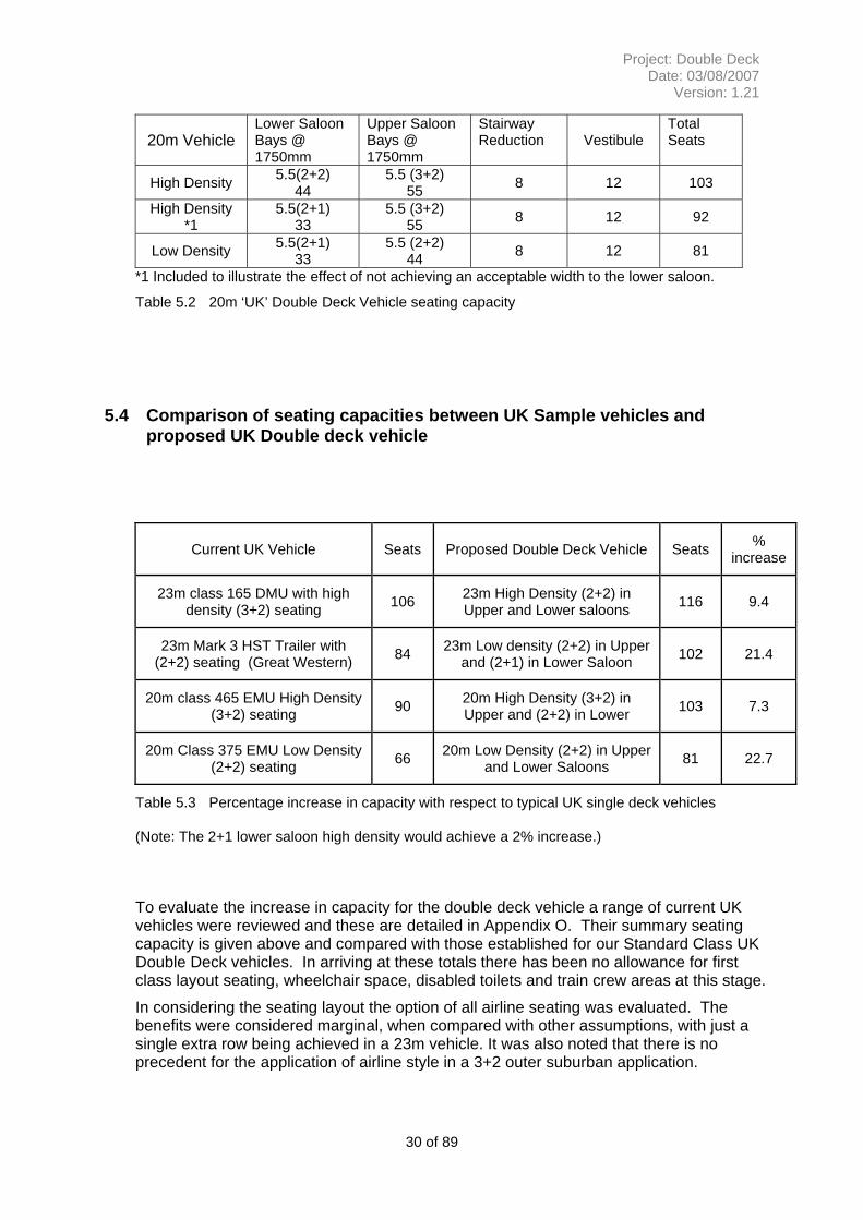
5.4 Comparison of seating capacities between UK Sample vehicles and proposed UK Double deck vehicle
Current UK Vehicle Seats Proposed Double Deck Vehicle Seats % increase
23m class 165 DMU with high density (3+2) seating 106 23m High Density (2+2) in
Upper and Lower saloons 116 9.4
23m Mark 3 HST Trailer with (2+2) seating (Great Western) 84 23m Low density (2+2) in Upper
and (2+1) in Lower Saloon 102 21.4
20m class 465 EMU High Density (3+2) seating 90 20m High Density (3+2) in
Upper and (2+2) in Lower 103 7.3
20m Class 375 EMU Low Density (2+2) seating 66 20m Low Density (2+2) in Upper
and Lower Saloons 81 22.7
Table 5.3 Percentage increase in capacity with respect to typical UK single deck vehicles
(Note: The 2+1 lower saloon high density would achieve a 2% increase.)
To evaluate the increase in capacity for the double deck vehicle a range of current UK vehicles were reviewed and these are detailed in Appendix O. Their summary seating capacity is given above and compared with those established for our Standard Class UK Double Deck vehicles. In arriving at these totals there has been no allowance for first class layout seating, wheelchair space, disabled toilets and train crew areas at this stage.
In considering the seating layout the option of all airline seating was evaluated. The benefits were considered marginal, when compared with other assumptions, with just a single extra row being achieved in a 23m vehicle. It was also noted that there is no precedent for the application of airline style in a 3+2 outer suburban application.
30 of 89
Project: Double Deck Date: 03/08/2007
Version: 1.21
5.5 Assessment of Seating Capacity for Proposed UK profile Double Deck Train Formations
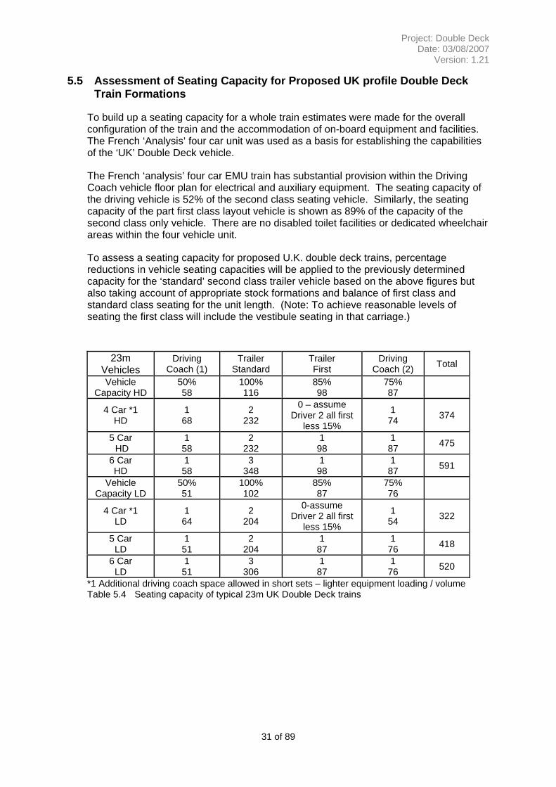
To build up a seating capacity for a whole train estimates were made for the overall configuration of the train and the accommodation of on-board equipment and facilities. The French ‘Analysis’ four car unit was used as a basis for establishing the capabilities of the ‘UK’ Double Deck vehicle.
The French ‘analysis’ four car EMU train has substantial provision within the Driving Coach vehicle floor plan for electrical and auxiliary equipment. The seating capacity of the driving vehicle is 52% of the second class seating vehicle. Similarly, the seating capacity of the part first class layout vehicle is shown as 89% of the capacity of the second class only vehicle. There are no disabled toilet facilities or dedicated wheelchair areas within the four vehicle unit.
To assess a seating capacity for proposed U.K. double deck trains, percentage reductions in vehicle seating capacities will be applied to the previously determined capacity for the ‘standard’ second class trailer vehicle based on the above figures but also taking account of appropriate stock formations and balance of first class and standard class seating for the unit length. (Note: To achieve reasonable levels of seating the first class will include the vestibule seating in that carriage.)
23m Vehicles
Driving Coach (1)
Trailer Standard
Trailer First
Driving Coach (2) Total
Vehicle Capacity HD
50% 58
100% 116
85% 98
75% 87
4 Car *1 HD
1 68
2 232
0 – assume Driver 2 all first
less 15%
1 74 374
5 Car HD
1 58
2 232
1 98
1 87 475
6 Car HD
1 58
3 348
1 98
1 87 591
Vehicle Capacity LD
50% 51
100% 102
85% 87
75% 76
4 Car *1 LD
1 64
2 204
0-assume Driver 2 all first
less 15%
1 54 322
5 Car LD
1 51
2 204
1 87
1 76 418
6 Car LD
1 51
3 306
1 87
1 76 520
*1 Additional driving coach space allowed in short sets – lighter equipment loading / volume Table 5.4 Seating capacity of typical 23m UK Double Deck trains
31 of 89
Project: Double Deck Date: 03/08/2007
Version: 1.21
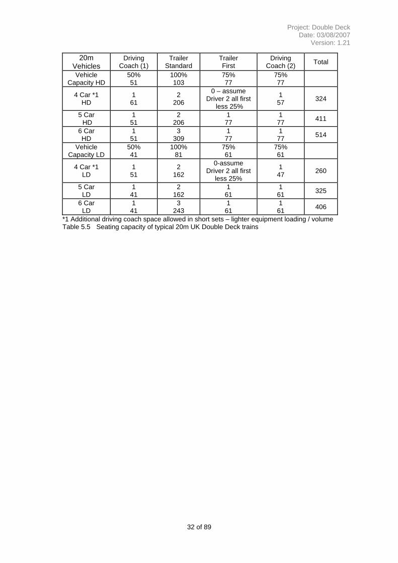
20m Vehicles
Driving Coach (1)
Trailer Standard
Trailer First
Driving Coach (2) Total
Vehicle Capacity HD
50% 51
100% 103
75% 77
75% 77
4 Car *1 HD
1 61
2 206
0 – assume Driver 2 all first
less 25%
1 57 324
5 Car HD
1 51
2 206
1 77
1 77 411
6 Car HD
1 51
3 309
1 77
1 77 514
Vehicle Capacity LD
50% 41
100% 81
75% 61
75% 61
4 Car *1 LD
1 51
2 162
0-assume Driver 2 all first
less 25%
1 47 260
5 Car LD
1 41
2 162
1 61
1 61 325
6 Car LD
1 41
3 243
1 61
1 61 406
*1 Additional driving coach space allowed in short sets – lighter equipment loading / volume Table 5.5 Seating capacity of typical 20m UK Double Deck trains
32 of 89
Project: Double Deck Date: 03/08/2007
Version: 1.21
6 LONG TRAINS
The impact of operating longer trains on the routes has been assessed by using existing data sources for platform lengths, gauging and route configuration. Where work has been identified then it has been sized into a range of tasks and valued in terms of works costs and disruption impact. The work required covers the extension of platforms, relocation of junctions and amendment of station layouts. Work to extend platforms can be straightforward and this is reflected at some locations. However, some will affect the associated junctions, signalling and will require land take. For some locations it is highly likely that additional land will not be available and for these the only available solutions will be to restrict or reduce facilities (junction size). In undertaking the analysis it was noted that issues of passenger loading and junction occupancy would be significant issues not being addressed in this study. A review of junction occupancy will also be required to confirm that the longer trains do not have a severe impact on the overall capacity of the network.
Depot provision has not been reviewed in depth. However, it is expected that lengthening is likely to be more expensive than the Double Deck option. Examples of work required include, additional land to accommodate the longer train lengths, depot connections would need to be moved and the provision of carriage sidings on the network would need confirming.
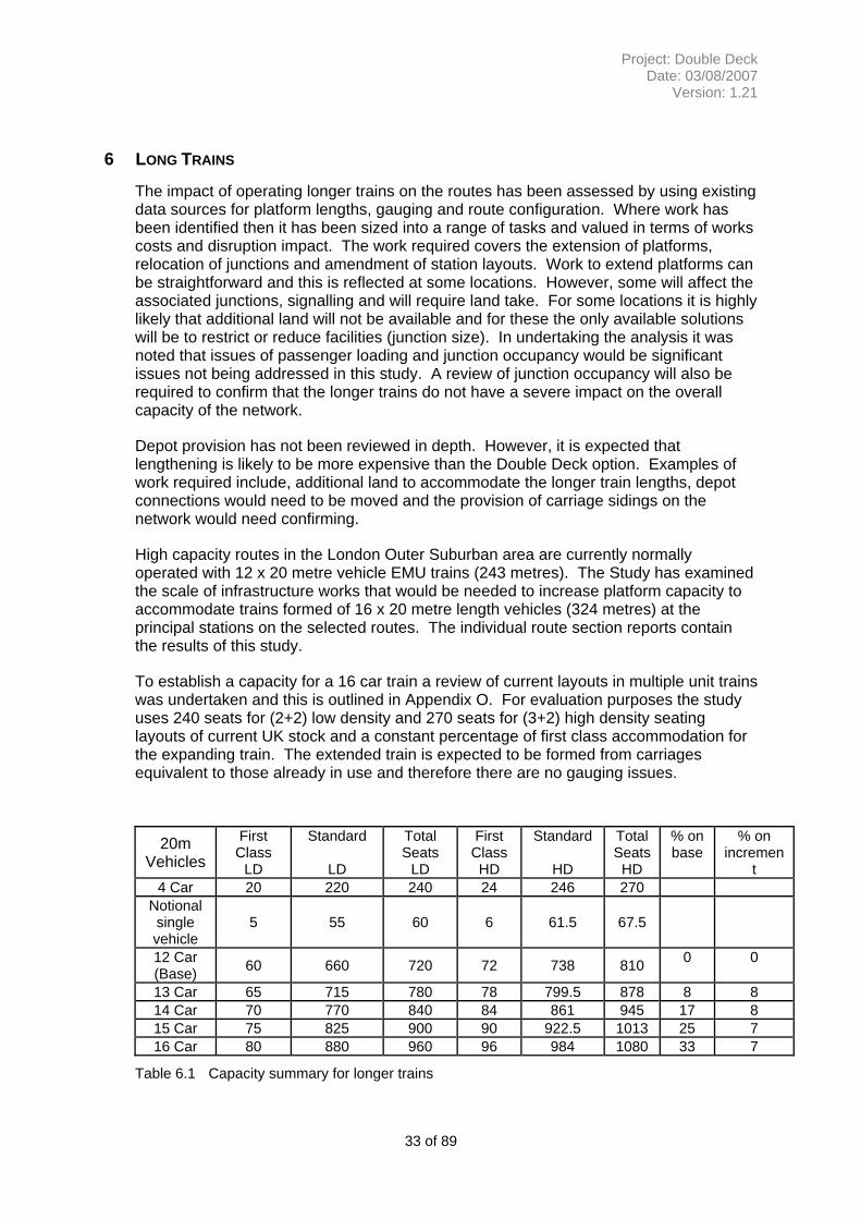
High capacity routes in the London Outer Suburban area are currently normally operated with 12 x 20 metre vehicle EMU trains (243 metres). The Study has examined the scale of infrastructure works that would be needed to increase platform capacity to accommodate trains formed of 16 x 20 metre length vehicles (324 metres) at the principal stations on the selected routes. The individual route section reports contain the results of this study.
To establish a capacity for a 16 car train a review of current layouts in multiple unit trains was undertaken and this is outlined in Appendix O. For evaluation purposes the study uses 240 seats for (2+2) low density and 270 seats for (3+2) high density seating layouts of current UK stock and a constant percentage of first class accommodation for the expanding train. The extended train is expected to be formed from carriages equivalent to those already in use and therefore there are no gauging issues.
20m Vehicles
First Class
LD
Standard
LD
Total Seats
LD
First Class HD
Standard
HD
Total Seats HD
% on base
% on incremen
t 4 Car 20 220 240 24 246 270
Notional single vehicle
5 55 60 6 61.5 67.5
12 Car (Base) 60 660 720 72 738 810 0 0
13 Car 65 715 780 78 799.5 878 8 8 14 Car 70 770 840 84 861 945 17 8 15 Car 75 825 900 90 922.5 1013 25 7 16 Car 80 880 960 96 984 1080 33 7
Table 6.1 Capacity summary for longer trains
33 of 89
Project: Double Deck Date: 03/08/2007
Version: 1.21
A 16 car the train gains a 33% additional seating over the 12 car. This is a reasonable and assured capacity increase. But the issue for this arrangement is would the extra seating be used or would individual behaviour of passengers still leave crush loading in the first four cars, or on the return loading at the exits of the country stations? This is where it is considered that additional measures would be required to evenly distribute the loadings throughout the trains and appropriate management of the distribution of passengers to achieve this and a reasonable dwell times.
34 of 89
Project: Double Deck Date: 03/08/2007
Version: 1.21
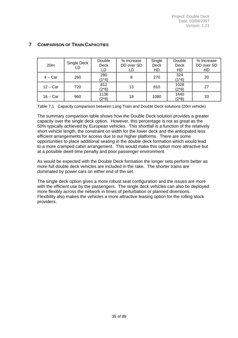
7 COMPARISON OF TRAIN CAPACITIES
20m Single Deck LD
Double Deck LD
% Increase DD over SD
LD
Single Deck HD
Double Deck HD
% Increase DD over SD
HD
4 – Car 260 280 (1*4) 8 270 324
(1*4) 20
12 – Car 720 812 (2*6) 13 810 1028
(2*6) 27
16 – Car 960 1136 (2*8) 18 1080 1440
(2*8) 33
Table 7.1 Capacity comparison between Long Train and Double Deck solutions (20m vehicle)
The summary comparison table shows how the Double Deck solution provides a greater capacity over the single deck option. However, this percentage is not as great as the 50% typically achieved by European vehicles. This shortfall is a function of the relatively short vehicle length, the constraint on width for the lower deck and the anticipated less efficient arrangements for access due to our higher platforms. There are some opportunities to place additional seating in the double deck formation which would lead to a more cramped cabin arrangement. This would make this option more attractive but at a possible dwell time penalty and poor passenger environment.
As would be expected with the Double Deck formation the longer sets perform better as more full double deck vehicles are included in the rake. The shorter trains are dominated by power cars on either end of the set.
The single deck option gives a more robust seat configuration and the issues are more with the efficient use by the passengers. The single deck vehicles can also be deployed more flexibly across the network in times of perturbation or planned diversions. Flexibility also makes the vehicles a more attractive leasing option for the rolling stock providers.
35 of 89
Project: Double Deck Date: 03/08/2007
Version: 1.21
8 INFRASTRUCTURE ASSESSMENT
The work required to enable the implementation of both Double Deck trains and Long Trains was assessed using the methodology outlined in section 3.4, namely using existing data sources for gauging and route configuration, establishing generic types of work and then applying broad cost estimates with assumptions for the extent and cost of service disruption.
This section discusses the findings of these reviews which were used to establish the selection of generic scope types based on a selection of railway construction limits and their variation over both time and geography. This shows how these typical work scopes have been derived and some of the findings for the assessed routes.
8.1 Double Deck – Work Items
Clearance from Over line Structures
To confirm the interpretation of the gauging analysis and the requirements for any new infrastructure a review of current and some historic design parameters was carried out. The findings are summarised in the table below:
Structures for OHLE routes Wire Height for OHLE Structure - Non Elec or DC routes
All (mm) Open Route Normal Restricted Open Full Restricted Normal Restricted
pre1950-58 *1 6500 4572 N/A 4500 4100
1958-80s 6500 4780 4640 MkI 4880 4315 4240 4640
80s- revised 6500 4780 4590 (4565) MkIII
4700 4315 4190 (4165*2)
*1 OHLE items introduced for DC1500v system *2 Special Reduced Clearances
Table 8.1 Summary of Structural clearance heights and wire heights
In assessing the clearance requirements these overall limits and typical design parameters have been used for interpreting the existing data sources and then in the notional specification of the work required. In establishing the need for work consideration has been given to the use of restricted and controlled clearances for the most costly items. For the specification of work the open route and normal clearances have been the default assumption with restricted options being considered where achievement of full clearance is driving a specific escalation in cost.
Clearance for GC and GB reference profiles for the assessment were derived with reference to the Network Rail standards requirement for a preferred clearance of minimum 200mm between the swept envelope of rolling stock and a structure. Hence it can be assumed that the for GB the requirement is 4350+200 giving 4550mm and for GC 4700+200 giving 4900mm.
36 of 89
Project: Double Deck Date: 03/08/2007
Version: 1.21
Hence when assessing for GB clearance on DC electrified lines and with reference to the requirements set out in table 8.1 the following conclusions were drawn:
• New and reconstructed overline structures with a horizontal deck built after around 1950 are likely to have sufficient clearance.
• Raising or reconstruction of other horizontal deck bridges or localised track lowering would otherwise be necessary.
• The majority of arch structures of normal proportions will need to be reconstructed or require localised track lowering.
For ‘GC’ height on DC electrified lines:
• The majority of existing horizontal deck structures would require to be raised or reconstructed or require localised track lowering to be undertaken.
• Structures built at the standard height of 4780mm may be retained with a maximum of 150mm localised track lowering or be subject to reduced clearance standards.
• All arch structures of normal proportions will need to be reconstructed.
For lines electrified on the overhead system, the extent of infrastructure alterations that would be required will initially be determined by the contact wire height.
For ‘GB’ height vehicles a clearance of 4350mm + 270mm static clearance to the OLE contact wire gives a target wire height of 4620mm above rail level.
• OLE contact wire height in open route conditions is normally a minimum of 4700mm.
• OLE contact wire height at overline bridges will be at a maximum of 4315mm above rail level therefore requiring re-grading and alterations to the OLE system wires in the vicinity of the bridge and raising or reconstruction of the overline bridge at all locations.
• Alternatively a track lowering solution of minimum 300mm.
For ‘GC’ height vehicles a clearance of 4700mm + 270mm static clearance to the OLE contact wire gives a target wire height of 4970mm above rail level
• 4970mm exceeds the wire height of all types of OLE equipment and therefore the entire OLE system would need to be modified to provide clearance for UIC ‘GC’ rolling stock.
• OLE contact wire height at over line bridges will be at a maximum of 4315mm above rail level and therefore raising or reconstruction of the over line bridge at all locations in conjunction with the OLE system alterations is required.
• It is not considered to be practicable to apply a track lowering solution for this depth of excavation (in excess of 600mm).
37 of 89
Project: Double Deck Date: 03/08/2007
Version: 1.21
Raising of Existing Over line Structures
The raising of existing over line structures having discrete deck construction mounted on bearings by co-ordinated jacking from temporary trestles placed in front of the abutment was extensively undertaken during earlier railway electrification schemes and can be achieved without damage to the structure during a road closure period of 6 to 9 weeks.
Associated service route alterations and diversions have a significant lead time and high cost.
Raising of a road level by the required 350mm for UIC ‘GB’ or 700mm for UIC’GC’ will potentially require extensive re-grading of highway alignments and modification of frontages in urban areas.
Integral structures such as a reinforced concrete portal cannot be raised without extensive alteration and a demolition and a reconstruction solution is likely to be more practicable.
Urban area over line structures with railway station building of traditional construction at street level will necessitate significant disruption to the station operation during demolition and bridge raising.
Railway intersection bridges (including Tramway crossings) will require an extended closure of the upper level route to alter the level of the infrastructure.
Lowering of Track in Existing Tunnels
Given that conventional railway tunnels have a curved arch form and experience with clearance of routes for operation of freight container traffic of conventional UK vehicle height generally requires some form of infrastructure works then it must be assumed that extensive works will inevitably be required to clear for double deck vehicles through tunnels.
Depending on the local geology, tunnel construction will normally have a dished profile invert or be stable without an invert in hard soil, chalk and rock formations.
Lowering of the track will require an extensive period of route closure for track removal, excavation, any drainage works and restoration of the track formation. The excavation work is a potentially risky operation and requires phased working to maintain support.
Reduction of rail level by installing a shallower construction slab track in place of a ballasted formation has been undertaken. With an existing dished tunnel invert there is the potential for there to be insufficient construction depth available above the invert to achieve the necessary depth of track lowering for double deck vehicles.
It is estimated that the works costs of lowering a double track tunnel by up to 500mm would be in the order of £15000 per metre and would require a substantial route closure for implementation.
For the purposes of this report this approach was considered inappropriate given the extent of route closure required and the construction risks from disturbing the tunnel. Further it was noted that there are no ready diversionary options for these major commuter links.
38 of 89
Project: Double Deck Date: 03/08/2007
Version: 1.21
New Construction of Tunnels
For a double track route the provision of suitable infrastructure for both UIC ‘GB’ and ‘GC’ vehicles can be achieved with relatively small disruption of railway operations by the construction of a new single track tunnel parallel with the existing alignment, the commissioning of the new tunnel bore and then slewing of a single line to the centre of the bore of the existing tunnel.
For a four track railway with two existing double track tunnel bores, the same principle but with the construction of a double track bore or flanking single track bores would apply.
Land take beyond the existing railway corridor to achieve suitable separation of new construction from the existing tunnel remaining under traffic to avoid disturbance of ground support would be a significant consideration.
Based on data from recent tunnelling works on the CTRL, It is estimated that works costs for new single line tunnel construction would be in the order of £25 million per single track tunnel kilometre (£40 million per mile) for lengths in excess of one kilometre with the unit rate increasing for shorter lengths.
Track alterations for conversion of a double track tunnel to single track including a provision for drainage works, slewing and track reinstatement is estimated at £5000 per metre.
Vehicle Gauging
The previous descriptions explain how the height, width and length of the vehicles were derived, as illustrated in Appendix M. This profile was then used with an assumed dynamic allowance for the gauging assessment for the impact of vehicle length and lateral displacement. These criteria were applied to the route for a ‘desk top’ assessment on the impact on curvature and major items of infrastructure which would be affected by the longer vehicles or the changes in end-throw and mid-throw. The extent of the work required resulted in the conclusion not to evaluate these options further as part of this report.
Track Lowering
Where the costs of bridge raising (or other obstruction) proved excessive then the option to lower the track has been adopted. It is accepted that this solution would generally increase maintenance costs and require detailed attention to the provision of drainage facilities. However, these costs would be considerably smaller on a whole life basis than the major construction item. Track lowering was considered achievable to a depth of around 400mm for depths greater than this work on the structure (or combination of the two) were used in the estimate.
Changes to other items of railway infrastructure
Alterations are likely to be required to the following:
• Traditional station canopies with fascias that extend up to or overhang the platform edge
• Underline bridges with overhead bracings
• Overhead signalling structures
Cost provision for these items will be covered by an allowance per route.
39 of 89
Project: Double Deck Date: 03/08/2007
Version: 1.21
• Alterations to depots and servicing point buildings
No specific assessment was made for the depots but a general provision was added to each route on the basis of reconstruction in existing sites to accommodate the taller vehicles. (On the assumption that 12 car lengths would already have been attained).
8.2 Long Train Work Items
Accommodation of Extra Long Trains – Junctions
The work required to accommodate the extra long trains in stations was completed by a general assessment of the station areas i.e. ‘free’ platforms, constrained by junctions, constrained by junction and access to land. The proposed solutions then considered the extent of the work required at an overall scheme level, rather than a detailed volume assessment. Although the practical availability of land was considered this was not formalised in terms of establishing ownership, or the cost of acquisition. In considering the likely schemes the loss of functionality was noted but assumed this would be successfully negotiated. The proposed future layouts would also be generally less flexible and would be more reliant of highly available infrastructure to achieve an acceptable service performance. These ‘lean’ layouts allow the junctions and station throats to be shorter than they are now and hence generate the space for the platforms.
Accommodation of Extra Long Trains – Stations
The stations and platform extensions are assumed to be of standard construction and provision of canopies and other platform facilities. The proposed services have limited stopping patterns and there is a general assumption that an application of Selective Door Opening (SDO) would be applied for any additional low passenger volume station stops that may be required to maintain a service. At this stage the impact of the longer trains on passenger flow and the measures necessary to equalise loading of the longer trains has not been assessed or included. It is expected that additional points of access and egress will be required to both disperse and distribute passengers for the full length of the train.
8.3 Cost Estimation
Description of Process
The aim of this overall assessment of the practicality and impact of the introduction of the two train types was to scale the likely costs against other current activity. Obviously from the initial level of the assessment it is not practical to produce a scheme or project estimate or price. However, to achieve a suitable scale reference was made to current project estimates which include all the elements which make up the costs to provide a suitably cost for comparison purposes between options. These assessments were done in two groups namely a collation of repetitive items for which a range of similar activities are grouped into generic blocks of activity and then given a common value. For other larger items then some assessment of scale and scope was then made and then the value adapted appropriately. A general allowance was added to each route for scope items not directly investigated (e.g. depots) and for other lesser works that are likely to be required as part of what would become major route upgrades. For all the routes a very general allowance was made for disruption (possession) costs.
In establishing a ‘cost’ for the routes some items were specifically excluded these included:- land acquisition costs, TWA costs, train costs, any power supply upgrade costs and as described in the station scope section any works required ‘beyond the
40 of 89
Project: Double Deck Date: 03/08/2007
Version: 1.21
platform edge’ at stations.
Generic Items
Five levels of generic work were developed and costs established for the work. The type cost and scope descriptions are outlined below:
Type A - £0.5-1.0 million per item
• Raise non-station footbridge • Existing arch replaced by metallic footbridge • Raise overhead bracing on truss underbridge
Type B - £1-2 million per item
• Reconstruction of 2-track arch in rural area road raised by up to 300mm • Raising of bridge superstructure by 400mm in rural areas • Raise 2 track station footbridge
Type C - £2-4 million per item
• Reconstruction of 2 track arch in urban area – road raised by up to 300mm • Reconstruction of 2 track arch in rural area – road raised by up to 750mm • Raising of bridge superstructure by up to 400mm in urban area • Raising of bridge superstructure by between 750mm and 1100mm in rural area • Raising 4 track station footbridge
Type D - £4-6 million per item
• Reconstruction of 2 track arch in urban area – road raised by up to 750mm • Raising of bridge superstructure by up to 750mm in urban area • Raising multi-track station footbridge • Raising of Intersection bridge by up to 300mm
Type E - £6-10 million per item
• Reconstruction of roadway and station building • Raising of bridge superstructure by between 750mm and 1100mm in urban area • Raising of Intersection bridge by between 300mm and 750mm
Specific Items
• Track Lowering
A review of current costs for track lowering was undertaken for a scope which included provision for the necessary drainage, changes to associated infrastructure and an allowance for difficult ground conditions. It was assumed that lowering in excess of 400mm was not a practical proposition.
Allow £250-400K per track per location for lowering of up to 150mm Allow £500-700K per track per location for lowering above 150mm
• Alterations to the OLE System
For the GB height vehicle it is expected that only the wire under the bridges will require raising (as the free wire height is clear). For this estimates for localised raising of existing OLE were generated and a figure of £100k to £200k per track applied. Where necessary an allowance of 10% was applied to allow for multi-track and station loop locations not covered in simple population analysis.
41 of 89
Project: Double Deck Date: 03/08/2007
Version: 1.21
To achieve clearance for GC height vehicles the OLE has to be raised throughout. Whilst this is not technically impossible a review did not identify any proven method to achieve this as a increment on the existing system. To establish a cost reference was made to recent studies for new electrification schemes. From this a figure of £0.7m-£1.0m per route km was derived for raising the OLE. Allowances were made for a proportion of new structures, new wire and associated support equipment. It was assumed that a method could be derived for maintaining service running whilst increasing the wire height along the route in stages. This was noted as a significant risk in terms of achievability and potential disruption (the disruption allowance was increased in these instances).
Estimate of possession costs
Given the variability in the possible scope and hence no realistic construction plans, a simplistic approach of a 30% increment on construction costs was used to support the comparison costs. In cases where access would be especially difficult then a complexity factor was applied. In terms of the nature of works those for the Double Deck solutions offer the greatest risk of variability and possible increase over the estimate as the nature of the work less well defined. Whilst not used directly in the cost comparisons it was noted that recent mainline blocks can cost around £1m per day. This figure was used to support the ‘no long term route closures’ approach to scope definition e.g. a 6 month closure for a tunnel widening on the Brighton Main line would not be tolerable or affordable.
42 of 89
Project: Double Deck Date: 03/08/2007
Version: 1.21
9 SUMMARY OF INFRASTRUCTURE ITEMS
Double Deck
The works required for each route are detailed in associated appendix and summarised in the table 9.1. The costs for the routes are in many ways comparable with a range of infrastructure obstructions and solutions. The GC option is consistently more expensive and in the case of the overhead electrified routes the cost and practicality of raising the wire is a major concern. As the GB sized coach gives an acceptable passenger compartment it and GC had no significant other advantages over GB that only the GB option would be used. The Double Deck works are in the main ‘civil’ works and therefore have the advantage of securing competitive rates from a broad range of suppliers, when compared with the more constrained rail specialist markets required for the longer train works. Hence the works element of the costs is attractive. As the methodology of the study used a flat rate for disruption it is possible that this is understated the comparison cost as many of the works will be highly disruptive.
Route
Electrification
Work Types A-E £m
Major Items (e.g. tunnels,
major structures,
rewiring) £m
Works Total £m
Disruption Allowance
(30%of mid) £m
Total £m
London Victoria/ London Bridge to Brighton GB
DC 3rd Rail 105-170 350-530 460-800 190
650-990
London Victoria/ London Bridge to Brighton GC
DC 3rd Rail 190-290 390-690 580-980 230 810-
1200
Liverpool St – Colchester and Ipswich GB
AC OHLE 200-390 200-295 400-785 180 580-
960
Liverpool St – Colchester and Ipswich London GC
AC OHLE 310-520 320-560 630-
1080 260 890-1340
Waterloo to Southampton GB
DC 3rd Rail 90-350 85-340 310-950 190 500-
1140 Waterloo to Southampton GC
DC 3rd Rail 130-530 100-410 375-
1200 235 610-1440
London Paddington to Reading and Oxford GB
AC OHLE 90-350 340-690 430-
1040 220 650-1260
London Paddington to Reading and Oxford GC
AC OHLE 140-570 370-860 510-
1430 290 800-1720
Table 9.1 Summary of infrastructure work activity and comparison costs for the introduction of Double Deck vehicles.
Comparing the work between the routes did not reveal significant differences other than the obvious route features. These are summarised below:
• On those routes with DC Electrification significant alterations to existing over line structures built prior to the 1960’s and/or lowering of the track formation is
43 of 89
Project: Double Deck Date: 03/08/2007
Version: 1.21
required. A substantial lowering of the track level in tunnels would be needed or the construction of a new single track tunnel allowing the existing tunnel to operate as a single line repositioned towards the centre of the tunnel bore.
• For those route with Overhead Electrification
o For UIC ‘GB’ vehicles, the raising of the majority of existing over line structures and localised modification to the OLE system over a length of around 500 metres in the vicinity of each structure
o For UIC ‘GC’ vehicles, the raising of the majority of existing over line structures and the modification of the entire overhead line electrification system to achieve the required electrical safety clearance.
• In reviewing the bridge, canopy and other overhanging structures the majority (in volume) can be addressed at reasonable cost and possession length. However, there are a number of what could be deemed exceptional structures which have a disproportionate cost. Examples of these include overlapping and interlaced bridges i.e. rail over rail over road where work will be required on all three levels, bridges carrying extensive property activities e.g. Croydon and occasional listed structures.
• Depot provision, a sum has been allowed for the construction of new facilities at the depots to accommodate the taller trains and some infrastructure amendments.
Where the routes coincide with those with an aspiration for greater freight capability then the GB option fulfils the majority of these aspirations. In most cases this is not needed for the routes closest to the London terminals – central is not a main destination for the container based traffic. However, items nearer the ports such as Southampton tunnel clearly benefit both freight and a Double Deck capability.
A brief review of the CTRL main line has been constructed to the mandated UIC ‘GC’ Reference Profile size and the larger 4650mm vehicle height could be operated on this route. Separate platforms have been provided at European platform gauge for international services and UK platform gauge for domestic services. This route shows how a Double Deck service could be efficiently introduced on a purpose built route. In summary the Double Deck option can be implemented but is costly for some relatively small gain in seats. There would be considerable disruption to the route and services in the construction of the route. However, the works required are relatively straightforward in an engineering sense. But each route does contain one or two significant challenges that require a further evaluation that the proposed solution is achievable. Long Trains
The work required to accommodate longer trains is more varied and is made up of railway infrastructure work. In terms of the layout changes, scope implications and likely costs this produced a more understood and known range of comparison costs. But the requirement for land was noted but not assessed in detail and assumptions were made as to its likely availability. In some cases (e.g. Brighton) the alterations to the junction will reduce the functionality available in order to secure the additional train lengths.
The assessments demonstrated a mixture of common themes and route specific issues. The nature and conclusions to the main items are discussed below:-
44 of 89
Project: Double Deck Date: 03/08/2007
Version: 1.21
• Work to extend platforms can be straightforward and this is reflected at some locations. However, some will affect the associated junctions, signalling and will require land take. In some cases the land may not be available in and restricted or reduced facilities (junction size) would be the only option.
• For effective dispersal at the terminal stations and for passenger loading at the feeder stations a considerable amount of flow management equipment will be required and this is not allowed for in this work.
• Depot provision has not been reviewed in depth. However, it is expected that lengthening is likely to be more expensive than the Double Deck option. Examples of work required include, additional land to accommodate the longer train lengths, depot connections would need to be moved and the provision of carriage sidings on the network would need confirming.
• The work showed that there could be optimal solutions between 12 and 16 vehicle formations which will require further work to confirm.
Route Associated
works £m
Major Items (e.g. major re-modelling) £m
Works Total £m
Disruption Allowance £m
Total £m
London Victoria/ London Bridge to Brighton
260-560 280-435 540-995 230 (30% of 780)
770-1225
Liverpool St – Colchester and Ipswich
240-360 260-560 500-920 220 (30% of 710)
720-1140
Table 9.2 Summary of infrastructure work activity and comparison costs for the introduction of Long Trains.
In summary the comparison costs for the works are more understood and the certainty of achieving the required functionality more assured than for Double Deck. The works are comparable in cost and do not generate high levels of additional capacity. Indeed the Double Deck costs feel relatively lower than those for the longer trains; this is likely to be due to the general civil engineering nature of the works. Where as the long trains require significant amounts of specialist rail activity. In order for the work to be completed with out major disruption it is proposed that the activity could be undertaken over some time to align with renewal works in the areas. Whilst the rolling stock for long trains is more flexible the infrastructure solutions can result in less flexible solutions which could constrain the capacity on other routes. Although fewer routes were assessed the findings are considered to be transferable to other routes.
45 of 89
Project: Double Deck Date: 03/08/2007
Version: 1.21
APPENDIX A – FRENCH NATIONAL RAILWAYS CLASS Z20500 EMU
46 of 89
Project: Double Deck Date: 03/08/2007
Version: 1.21
47 of 89
Leading dimensions of the analysis vehicle are:
• 26100mm body length • 20000mm bogie centres • Internal saloon width of 2690mm • 5250mm end vestibule (1) with 4 seats in (2+2) layout and a standard toilet compartment • 5250mm end vestibule (2) with 8 seats in (2+2) layout • 1800mm width doorway to vestibules • 15400mm central saloon seating arranged in 10 bays of facing (3+2) seating with a bay length of 1540mm • 2 seats missing from the base layout described above where stairways enter the saloon areas at four locations • Individual seat width of 452mm without armrests • Gangway width of 432mm between seats groups
The installed seating layout with a 1540mm bay length compares with recent UK practice of 1770mm for main line stock and 1700mm for LUL Tube stock and may be regarded as unacceptably cramped for the intended outer suburban use.
Project: Double Deck Date: 03/08/2007
Version: 1.21
Project: Double Deck Date: 03/08/2007
Version: 1.21
48 of 89
48 of 89
Project: Double Deck Date: 03/08/2007
Version: 1.21
49 of 89
Project: Double Deck Date: 03/08/2007
Version: 1.21
d
Trailer First
Driving Coach (2) Total
75% 138
50% 92
0 – assume Driver 2 all first
less 1/3
1 60 520
1 138
1 92 690
1 138
1 92 874
nch comparison Double Deck Train. (Seating
Deriving UK seating from French layout - This French vehicle used for the main comvehicle Standard Class layout with 3+2 ahas 204 seats This seat pitch is too close for UK applica1540mm in the saloon. Hence for compabays has been reduced by one to give - 9losing 2 bays of 10 seats (upstairs and doHD capacity for comparison is 204-20 = 1By applying a mix for driving vehicles (50Composite (75% of standard) a train capatable A.1.
26m Vehicles
Driving Coach (1)
Trailer Standar
Vehicle Capacity
50% 92
100% 184
4 Car HD
1 92
2 368
5 Car HD
1 92
2 368
6 Car HD
1 92
3 552
Table A.1 – Seating capacity of Freadjusted for UK spacing.)
parison is a 26m t 1540mm bay length
tion – 10 bays at rison the number of bays at 1711mm wnstairs) so a revised 84 % reduction) and city was derived – see
50 of 89
Project: Double Deck Date: 03/08/2007
Version: 1.21
APPENDIX B - GERMAN RAILWAYS BOMBARDIER DOUBLE DECK PUSH PULL COACHES
Operator Deutsche Bahn AG
Length 27,270 mm (driving coach) 26,800 mm (intermediate coach)
Note the comparatively inefficient use of space and low number of seating compared to the French vehicle used for reference (Appendix A).
51 of 89
Project: Double Deck Date: 03/08/2007
Version: 1.21
APPENDIX C - COMPARISON OF MAINLAND EUROPE PASSENGER VEHICLE DIMENSIONS
Table A shows static vehicle leading dimensions for a variety of mainland Europe passenger vehicles and in comparison with the UIC static reference profiles.
All of the modern (post 1960) main line rolling stock covered in the table has a conventional curved roof profile.
STANDARD VEHICLES
Vehicle D with a length over buffers of 26400mm, bogie centres of 19000mm, static vehicle height of 4050mm above rail level and static vehicle width of 2825mm shows the leading dimensions of the standard UIC Passenger vehicle and the majority of vehicles built after 1960 conform to this size.
The dimensions of mid-20th Century vehicles A, B and C demonstrate the decrease in vehicle static body width compared with the UIC static Reference Profile width of 3150mm with increasing body length.
Vehicle E shows the leading dimensions for Couchette and Sleeper vehicles that match the standard UIC coach length and width but has a 200mm greater body height of 4250mm above rail level corresponding to the ‘Berne Gauge’.
DOUBLE DECK VEHICLES
Vehicles G and H show leading dimensions of 1950’s origin double deck vehicles that were operated by German National Railways (DB) and had a vehicle height of 4520mm above rail level. Vehicle H has the same length and width dimensions as the standard UIC passenger coach (Vehicle D).
Vehicles I and J show modern developments of the standard 26400mm double deck vehicle size for vehicles that have operated widely in Germany and elsewhere in central Europe since the early 1990’s with increased bogie centres to maximise the length of the lower saloon area and a static vehicle height of 4630mm above rail level to suit the Central European Administrations static vehicle height of 4650mm that corresponds with the UIC ‘GC’ Reference Profile.
Vehicle K shows a slightly lengthened overall body length for a Driving Trailer coach having a tapering overhang extension of the driving cab beyond the base vehicle length.
French National Railways (SNCF) has operated double deck vehicles in both EMU and locomotive hauled formations since the 1980’s predominantly on the Paris suburban system and Vehicle L shows dimensions of the locohauled vehicle.
Recent vehicle builds are to the standard UIC coach length of 26400mm and have 20000mm bogie centre. The static vehicle height is 4320mm above rail level that suits traditional French infrastructure and corresponds with the UIC ‘GB’ Reference Profile.
SNCF have developed the double deck TGV ‘Duplex’ for 300kph operation on high speed routes constructed since 1980. These trains are the standard articulated bogie form of the TGV train fleet with 17800mm vehicle length for trailers. The vehicles also have a static vehicle height of 4320mm above rail level corresponding to UIC ‘GB’ Reference Profile.
The curved roof profile encroaches into the cross-section of the upper saloon from
52 of 89
Project: Double Deck Date: 03/08/2007
Version: 1.21 approximately shoulder height when in a seated position.
Railway operators with a more generous loading gauge, such as in the United States, can allow a full rectangular cross section in the Upper saloon.
The ‘Talgo’ train formation design originating in Spain with 11.7m vehicles mounted on single axle wheelsets avoids the need for a raised floor level over the bogie area. The arrangement allows a two level through gangway between coaches in double deck stock with overall fewer stairways and therefore less space utilised in the train formation but having an impact on internal circulation within the vehicle and therefore station dwell time.
53 of 89
Project: Double Deck Date: 03/08/2007
Version: 1.21
TABLE A - COMPARISON OF EUROPEAN MAINLAND PASSENGER COACH LEADING DIMENSIONS
Germany K 27270 26600 20000 2774 4630## 1995 Modern Double Deck Driving Trailer
France L 24280 23980 17800 2846 4320 1973 Locomotive Hauled Coach
France M 26400 26100 20000 2806 4320 1995 Z20500 EMU
54 of 89
Project: Double Deck Date: 03/08/2007
Version: 1.21
APPENDIX D – PROPOSED UK PROFILE VEHICLE CROSS-SECTIONS
GC PROFILE VEHICLE (‘23m’)
Min. Gangway
Min. Gangway
Rail to Floor Floor Ceiling &
Roof Cabin Height
Vehicle Total
Tolerance
Design Total
Allowance (mm) 250 90 75 2080 4650 50 4700
55 of 89
Project: Double Deck Date: 03/08/2007
Version: 1.21
GB PROFILE VEHICLE (‘23m’)
Min. Gangway
Min. Gangway
Rail to Floor Floor Ceiling &
Roof Cabin Height
Vehicle Total
Tolerance
Design Total
Allowance (mm) 250 80 75 1920 4320 30 4350
56 of 89
Project: Double Deck Date: 03/08/2007
Version: 1.21
APPENDIX E – LONDON VICTORIA AND LONDON BRIDGE TO BRIGHTON ROUTE
The Study has reviewed the need for changes to the current infrastructure to permit:
• Introduction of UIC ‘GB’ Profile Double Deck rolling stock (4350mm vehicle height above rail level) operating in 12 x 20m vehicle EMU formations between Victoria and Brighton.
• The incremental cost of introducing UIC ‘GC’ Profile Double Deck rolling stock (4650mm vehicle height above rail level) rather than GB Profile
• Modification of the infrastructure to allow operation of 16 x 20m vehicle trains using conventional EMU stock.
The London to Brighton line is approximately 50 route miles.
It is assumed that the service to the branching routes towards East Grinstead, Eastbourne and Littlehampton/Bognor Regis/Portsmouth will continue to be operated by conventional EMU stock.
It is assumed that by the time of implementation of any changes to the rolling stock fleet, that the current service from Brighton to London Bridge and beyond will have been taken over by Thameslink through services and London Bridge (Central side) will then be limited to inner Suburban routes.
The London to Brighton line is electrified using the d.c. Conductor rail system. The route is currently proportioned for maximum 12 x 20m vehicle operation.
DOUBLE DECK ROLLING STOCK
On the route from London Victoria to Brighton via the Quarry Line the Study has reviewed 84 Overline Structures and 6 Tunnels.
For the alternative main line route through Redhill, there are 3 additional overline structures and 1 tunnel.
To simplify the assessment of costs for infrastructure work, alterations have been allocated to one of five works categories as follows:
Works type A-E for ‘GB’ & ‘GC’ Double Deck Stock
Type Rate £m GB Volume GBTotal £m GC Volume GC Total £m
A 0.5-1.0 7 35 10 5
B 1.0-2.0 12 24 2 2
C 2.0-3.0 23 46 15 30
D 4.0-6.0 5 20 24 96
E 6.0-10.0 4 24 9 54
Total (Range) £m 105 - 170 Total (Range) £m 190-290
57 of 89
Project: Double Deck Date: 03/08/2007
Version: 1.21
Individual Items for ‘GB’ Double Deck Stock Location Activity £m
Victoria Station Track lowering by 300mm 30-45
East Croydon Station Track lowering by 250mm 35-45
Total 65-90
Individual Items for ‘GC’ Double Deck Stock Location Activity £m
Victoria Station Track lowering by 750mm 50-80
East Croydon Station Track lowering by 600mm 30-50
Gatwick Airport Station Track lowering 400mm 10-15
Patcham Motorway bridges Track lowering 400mm 2-4
Total 90-150
Individual Items for ‘GB’ and ‘GC’ Stock (Tunnels) Location Activity £m
Quarry Tunnel 1m 353 yd 1933
Redhill Tunnel 649yd 593
Merstham Tunnel 1m 71yd 1675
Balcombe Tunnel 1141 yd 1044
Haywards Heath Tunnel 249yd 227
Clayton Tunnel 1m 499yd 2067
Patcham Tunnel 492 yd 450
Total Aggregate length 7989m Rate £20-35m /km* 160-280
Supporting Items for GB and GC Stock Item Activity £m
Depot Provision Modification to accommodate DD stock 80-120
Station Modifications Platform work to enable DD operation 20-50
Other infrastructure works Supporting work for gauge clearance, junction modifications, etc. 40-90
Total 140-260
58 of 89
Project: Double Deck Date: 03/08/2007
Version: 1.21 Summary of Double Deck works and costs for the route Work Type GB £m GC £m
Low High Low High
A-E 105 170 190 290
Individual Items 215 370 250 430
Supporting Items 140 260 140 260
Works Total 455 800 580 980
Disruption Assessment 190 230
Total 650 990 810 1200
INITIAL ASSESSMENT OF INFRASTRUCTURE CHANGES FOR EXTRA LONG TRAINS
Summary of Activity for Significant Sections of the Route
Order of cost for alterations at principal stopping points to accommodate 16 car x 20m train on route currently proportioned for 12 car x 20m. Alterations will normally impact on signalling and track layouts with works costs for platform works being a relatively small component. In some cases land take will be required to accommodate the extended trains the costs of this are not included. For some junctions the only practical (and economical) solution will be to restrict their functionality and capability.
VICTORIA
Assume that platform extension back into the present ‘Central’ Concourse area is not acceptable. Extension of the current 12 x 20m capacity platforms would need additional width for around 90 metres in the area where the tracks converge into the throat of the track layout departing the Station. Some space available on the Up (west) side of the area that is currently occupied by a substantial brick building that was the Signal Box and is now staff accommodation. Further space on the west side is occupied by a vehicle ramp/access serving the Up Carriage Sidings area and British Transport Police Headquarters building. Layout is constrained by Elizabeth Bridge and Ebury Bridge crossing the platform/throat area. Substantial alterations to the track layout and signalling would be required. Order of cost £75m to £100m
CLAPHAM JUNCTION
Layout fixed at country end by: - Falcon Junction where the West London Line joins the Brighton Slow Lines immediately
at the platform ends - Convergence of the Brighton Line and South West Main Line (Waterloo to Bournemouth)
routes at standard track intervals in a cutting flanked with substantial retaining walls structures.
Ladder crossover situated at London end of platforms linking all four tracks could be displaced further towards London or eliminated.
59 of 89
Project: Double Deck Date: 03/08/2007
Version: 1.21 Significant curvature on all Brighton Line platforms Envisage extension of platforms towards London and realignment of reverse curvature on Slow Lines by repositioning the West London Line platforms towards London thereby releasing width for construction. Order of Cost £30m to £50m
EAST CROYDON
Layout constrained by: - Current station buildings on London Road bridge at the country end of the platforms - Croydon Tramlink tracks and interchange platforms located on London Road bridge - Multiple crossover track layouts at country end of station area - Multiple crossover track layouts at London end of station area
Significant wideway between Platforms 2 and 3 Layout fixed at Windmill Bridge Junction located 650m from London end of platforms where Victoria and London Bridge routes merge. Envisage extending platforms towards London using space in the wideway, the former Goods Yard area on Up side (currently used as an infrastructure maintenance depot) and displacing tamper siding area at London end of the Yard. Widened layout constrained by St James Road overbridge at 400m from current end of platforms Assume Platforms 5 and 6 on east side serving Slow lines retained at current 12 car capacity Order of Cost £40m to £60m
REDHILL
Layout fixed by junctions towards Tonbridge and Reigate immediately at country end of platforms. Two track approach from London with formation width expanding to 4 track width for loops and sidings at around 400m from London end of current platforms. Envisage extending platforms towards London with rationalisation of sidings and loops/crossovers Order of Cost £20m to £40m
GATWICK AIRPORT
Two sets of ladder crossovers immediately at London end of platforms for crossing Gatwick Express Services from Brighton Fast lines to dedicated Platforms 1 and 2 Ladder crossover at Tinsley Green Junction located 900m south of country ends of platforms Up side loop and sidings immediately at country ends of platforms Aircraft runway trip wires commence 50 metres south of current end of station platforms. Platform extensions at both ends within current constraints would require substantial layout alterations to crossovers and platform loops. Order of Cost £40m to £60m
THREE BRIDGES
Layout fixed by junction with Horsham line immediately at country end of Slow Line platforms. Layout constrained by ladder crossover across all four tracks at London end of station commencing around 200m from platform ends. Underbridge crossing main road at London end of platforms
60 of 89
Project: Double Deck Date: 03/08/2007
Version: 1.21 Envisage extending platforms towards London requiring infill bridgeworks and alterations to Up side Slow lines layout Order of Cost £20m to £40m
HAYWARDS HEATH
Current layout is two island platforms serving Down Main/Down Loop and Up Main/Up Loop lines Layout fixed by Haywards Heath Tunnel at 400 metres from country ends of platforms Platform loops extend towards London for around 800 metres and there is an adequate wideway between the tracks to extend the platforms without requiring layout alterations Order of Cost £15m to £25m
BRIGHTON
Layout constrained by Montpelier Junction and associated crossovers for line to Lewes at around 150 metres from London end of current platforms. Layout constrained by connection from West Coast Line towards Portsmouth within station area and Rolling Stock maintenance depot on Up side (west) of layout on approach to station. Substantial space available on Down side in a goods yard area for general widening of the layout on approach to platforms and repositioning of crossovers. Envisage extension of central island platforms 4,5 and 6 and possibly 3 and reduced interconnection with the East Coast (Lewes) line. Other platforms for East and West Coast routes retain current 12 x 20m platform capacity Order of Cost £40m to £60m
Individual Items for Long Trains
Location £m
Victoria 75-100
Clapham Junction 30-50
East Croydon 40-60
Redhill 20-40
Gatwick Airport 40-60
Three Bridges 20-40
Haywards Heath 15-25
Brighton 40-60
Total 280-435
61 of 89
Project: Double Deck Date: 03/08/2007
Version: 1.21 Supporting Items for Extra Long Trains
Item Activity £m
Depot Provision Extension and reconfiguration to accommodateD longer trains 130-200
Station Modifications Platform works to accommodate longer 80-180
Other infrastructure works Supporting work for gauge clearance, junction modifications, etc. 130-200
Total 260-560
Summary of ‘Extra Long Train’ works and costs for the route
Work Type £m
Low High
Individual Items 280 435
Supporting Items 260 560
Works Total 540 995
Disruption Assessment 230
Total 770 1225
62 of 89
Project: Double Deck Date: 03/08/2007
Version: 1.21
APPENDIX F – LONDON LIVERPOOL STREET TO IPSWICH ROUTE
The Study has reviewed the need for changes to the current infrastructure to permit:
• Introduction of UIC ‘GB’ Profile Double Deck rolling stock (4350mm vehicle height above rail level) operating in 12 x 23m vehicle EMU formations between Liverpool St and Ipswich.
• The incremental cost of introducing UIC ‘GC’ Profile Double Deck rolling stock (4650mm vehicle height above rail level) rather than GB Profile
• Modification of the infrastructure to allow operation of 16 x 20m vehicle trains using conventional EMU stock.
The Liverpool Street to Ipswich line is approximately 69 route miles.
It is assumed that the service to the branching routes towards Southend, Clacton and Harwich will continue to be operated by conventional EMU stock.
The Liverpool Street to Shenfield section of the route was electrified on the 1500 volt d.c. system in the late 1940’s. The system was converted to 6.25kV a.c. in the suburban area and 25kV in the outer area using the same overhead line equipment and progressively extended to Colchester and Clacton in the late 1950’s/early 1960’s using Mark 1 equipment. The section from Colchester to Ipswich was electrified on the 25kV a.c. system when electrification was extended to Norwich in the mid-1980’s. Sections of the route operating at 6.25kV were subsequently converted to 25kV. This combination of standards has resulted in a variety of wire heights and clearances which makes a summary assessment difficult. However, renewals in the southern section will regularise some of these over the next five years. A general allowance has been made for further work.
The route is currently proportioned for maximum 12 x 20m vehicle operation.
DOUBLE DECK ROLLING STOCK
On the route from London Liverpool Street to Ipswich the Study has reviewed 112 over line Structures and 1 Tunnel.
To simplify the assessment of costs for infrastructure work, alterations have generally been allocated to one of five works categories as follows:
Works type A-E for ‘GB’ & ‘GC’ Double Deck Stock
Type Rate £m GB Volume GBTotal £m GC Volume GC Total £m
A 0.5 13 6.5 14 7
B 1.0 25 25 5 5
C 2.0 28 56 36 72
D 4.0 15 60 18 72
E 6.0 5 30 20 120
Total (Range) £m 200-390 Total (Range) £m 305-515
63 of 89
Project: Double Deck Date: 03/08/2007
Version: 1.21 Individual Items for ‘GB’ Double Deck Stock
Location Activity £m
Liverpool St Track lowering by 150mm 30-40
40 – 4 track OLE sections
54 – 2 track OLE sections
Raising contact wire height 30-60
Total 60-100
Individual Items for ‘GC’ Double Deck Stock
Location Activity £m
Liverpool St Track Lowering by 400mm 40-60
20 miles 4 track OLE
50 miles 2 track OLE
180 track miles / 288 track km of wire raising. £20m associated works. Incorporating a1.5 complexity factor.
180-250
Total 220-310
Individual Items for ‘GB’ and ‘GC’ Stock (Tunnel)
Location Activity £m
Ipswich Tunnel 361 yards / 330m of new single track tunnel* 12-50
Ipswich Tunnel Re-work slab track 8-20
Total 20-70
*Includes £2m for layout alteration at country end portal adjacent to Ipswich Station = £2m
Supporting Items for GB and GC Stock
Item Activity £m
Depot Provision Modification to accommodate DD stock 80-120
Station Modifications Platform work to enable DD operation 20-50
Other infrastructure works Supporting work for gauge clearance, junction modifications, etc. 40-90
Total 140-260
64 of 89
Project: Double Deck Date: 03/08/2007
Version: 1.21
Summary of Double Deck works and costs for the route
Work Type GB £m GC £m
Low High Low High
A-E 200 390 305 515
Individual Items 80 170 240 380
Supporting Items 140 260 140 260
Works Total 420 820 685 1150
Disruption Assessment* 370 410
Total 790 1190 1095 1560
*Factor increased to 0.6 to reflect additional complexity of the work areas.
INCREASED LENGTH TRAIN
Order of cost for alterations at principal stopping points to accommodate 16 car x 20m train on route currently proportioned for 12 car x 20m.
Alterations will normally impact on signalling and track layouts with works costs for platform works being a relatively small component.
Details of the logic behind the direction of the lengthening and constraints are separately listed.
65 of 89
Project: Double Deck Date: 03/08/2007
Version: 1.21 Individual Items for Long Trains
Location £m
Liverpool Street 80-120
Stratford 30-40
Romford 10-20
Shenfield 30-40
Chelmsford 10-20
Witham 15-20
Marks Tey 5-10
Colchester 30-40
Manningtree 5-10
Ipswich 30-40
Total 245-365
Supporting Items for Extra Long Trains
Item Activity £m
Depot Provision Extension and reconfiguration to accommodateD longer trains 130-200
Station Modifications Platform works to accommodate longer 80-180
Other infrastructure works Supporting work for gauge clearance, junction modifications, etc. 130-200
Total 260-560
66 of 89
Project: Double Deck Date: 03/08/2007
Version: 1.21 Summary of ‘Extra Long Train’ works and costs for the route
Work Type £m
Low High
Individual Items 245 365
Supporting Items 260 560
Works Total 505 925
Disruption Assessment 215
Total 720 1140
67 of 89
Project: Double Deck Date: 03/08/2007
Version: 1.21
APPENDIX G – LONDON PADDINGTON TO READING AND OXFORD
INFRASTRUCTURE WORKS TO PROVIDE FOR DOUBLE DECK TRAIN
Route Summary -
• 106 over line structures reviewed • No tunnels on route section • Overhead electrification from Paddington to Heathrow Airport Junction area
(approximately 11 miles) installed in 1994 - made significant use of ‘Reduced Clearance’ provision (contract wire 4190m above rail) to avoid infrastructure costs for bridge alterations on various large structures near to London
• 6 tracks from Paddington to Old Oak (3½ route miles), 4 tracks from Old Oak to Didcot area (50 route miles), 2 tracks from Didcot area to Oxford (10 route miles)
Summary of Works Costs -
Review of route undertaken from images of overl ine structures (rather than gauging data) Analysis shows count of standard solutions A to E Track lowering applied for significant structures as listed No specific allowance has been made for the effect of Crossrail on the route assessment could be beneficial for some structures and the new overhead line extension to Maidenhead – provided the additional costs of passive provision for the taller vehicle is included in the scope.
Specific Sites
PADDINGTON TO OLD OAK AREA (6 TRACKS)
Westbourne Bridge A40 Feeder Lord Hill Bridge Great Western Road Goldbourne Road Ladbroke Grove Road Old Oak Flyover Intersection Scrubbs Lane Park Mitre Bridge
Lowering 6 tracks £2m per site for GB, £4m per site for GC
OLD OAK TO READING AREA
Acton Intersection Bridge A 40 Western Avenue Horn Lane / Acton Main Line Station Noel Road District / Piccadilly Line Intersection over Dawley Road Heathrow Junction Flyover Intersection M4 Ringway
Lowering 4 tracks £2m per site for GB, £4m per site for GC
EXCEPTIONAL STIES FOR ALTERATIONS TO STRUCTURES
• Ealing Broadway Station (Type E) • Ealing Broadway Car Park (Type E) • Southall Station Overbridge (Type E) • Hayes Station Overbridge (Type E)
Works type A-E for ‘GB’ & ‘GC’ Double Deck Stock
GB GC
Type Rate £m Volume Total £m Volume Total £m
A 0.5 15 7.5 15 7.5
B 1.0 31 31 16 16
C 2.0 25 50 39 78
D 4.0 0 0 4 16
E 6.0 4 24 4 24
Total (Range) 88.5-354 Total (Range) 142-566
Individual Items for ‘GB’ Double Deck Stock
Location Activity £m
OLE – Paddington to Heathrow Airport Jcn
Raise wire height at specific locations to clear GB
150-250
General Track lowering 45-180
Total 195-430
69 of 89
Project: Double Deck Date: 03/08/2007
Version: 1.21
Individual Items for ‘GC’ Double Deck Stock
Location Activity £m
General Track Lowering for GC 88-250
OLE – Paddington to Heathrow Airport Jcn
Raise wire height at specific locations to clear GB 142-350
Total 230-600
Supporting Items for GB and GC Stock
Item Activity £m
Depot Provision Modification to accommodate DD stock 80-120
Station Modifications Platform work to enable DD operation 20-50
Other infrastructure works Supporting work for gauge clearance, junction modifications, etc. 40-90
Total 140-260
Summary of Double Deck works and costs for the route
Work Type GB £m GC £m
Low High Low High
A-E 88.5 354 142 566
Individual Items 195 430 230 600
Supporting Items 140 260 140 260
Works Total 425 1044 510 1430
Disruption Assessment 220 290
Total 650 1260 800 1720
70 of 89
Project: Double Deck Date: 03/08/2007
Version: 1.21
APPENDIX H – LONDON WATERLOO TO SOUTHAMPTON
INFRASTRUCTURE WORKS TO PROVIDE FOR DOUBLE DECK TRAINS
Route Summary
• 134 over line structures reviewed • Waterloo to Southampton is approximately 80 route miles (130 route km) • 6 tunnels on route with aggregate length 1.55km • Route electrified on 3rd rail system • 4 tracks from Waterloo to Basingstoke (Worting Junction) (50½ route miles) plus
some running and platform loops. • 2 tracks from Worting Junction to Southampton (30 route miles) plus some running
and platform loops.
Works Summary
• Review of route undertaken from images of overline structures (rather than gauging information)
• Analysis shows count of standard solutions A to E • Track lowering or significant reconstruction / alterations listed individually.
Specific Items
STEWARTS LANE AREA
South West Main Line intersects with following routes Below Nine Elms flyover at 2m 31ch Above Stewarts Lane Low level lines at 2m 37ch Below Victoria (Eastern) Main Line at 2m 42ch Below Atlantic Lines at 2m 51ch Below Victoria (Central) Main Line at 2m 62ch
South Western Main Line is elevated above ground level with frequent underline structures. Significant track lowering would therefore be problematical. Review assumes:
Modify Stewarts lane Low Level underbridge to reduce construction depth £2m GB / £3m GC
Raise Station Footbridge (Type E) Raise St Johns Road Over bridge (Type E)
WIMBLEDON AREA
Lower 2 tracks under up slow line flyover - £3m for GB- £5m for GC Alterations to over line structures at Wimbledon Stations £13m for GB and £15mGC
71 of 89
Project: Double Deck Date: 03/08/2007
Version: 1.21 BASINGSTOKE CANAL AQUEDUCT
Replace 4 single line tunnel structure including track lowering - £5m for GB - £8m for GC
Works type A-E for ‘GB’ & ‘GC’ Double Deck Stock
GB GC
Type Rate £m Volume Total £m Volume Total £m
A 0.5 18 9 18 9
B 1.0 41 41 14 14
C 2.0 14 28 35 70
D 4.0 1 4 7 28
E 6.0 1 6 2 12
Total (Range) 88-352 Total (Range) 133-532
Individual Items for ‘GB’ Double Deck Stock
Location Activity £m
Nine Elmes Eurostar connections over 6 lines
Lower 4 tracks for SW Main Lin- £3m for GB (2 Windsor Line tracks not lowered)
3
Stewarts Lane Area Modify Low Level underbridge to reduce construction depth £2m GB Raise Victoria Eastern Viaduct £10m GB Raise Atlantic Lines £5m GB Lower track below Victoria (Central) bridge £2m GB
19
Wimbledon Lower 2 tracks under up slow line flyover £3m for GB Alterations to over line structures at Wimbledon Stations £13m for GB
13
Basingstoke Canal Aqueduct
Replace 4 single line tunnel structure including track lowering -£5m for GB
5
General Track lowering 9
Total (inc Estimate Range) 40-295
72 of 89
Project: Double Deck Date: 03/08/2007
Version: 1.21 Individual Items for ‘GC’ Double Deck Stock
Location Activity £m
Nine Elmes Eurostar connections over 6 lines
Lower 4 tracks for SW Main Lin- £5m for GC (2 Windsor Line tracks not lowered)
5
Stewarts Lane Area Modify Low Level underbridge to reduce construction depth £3m for GC Raise Victoria Eastern Viaduct £15m GC Raise Atlantic Lines £8m GC Lower track below Victoria (Central) bridge £3m GC
29
Wimbledon Lower 2 tracks under up slow line flyover £5m for GC Alterations to over line structures at Wimbledon Stations £15m for GC
20
Basingstoke Canal Aqueduct
Replace 4 single line tunnel structure including track lowering -£8m for GC
8
General Track lowering 17
Total (inc Estimate Range) 57-365
Individual Items for ‘GB’ and ‘GC’ Stock (Tunnel)
Location Activity £m
Litchfield Tunnel 181m
Popham No1 242m
Popham No2 182m
Wallers Ash 458m
1546m @ £25m/km 30
Southampton 483m 15
Total 45
Supporting Items for GB and GC Stock
73 of 89
Project: Double Deck Date: 03/08/2007
Version: 1.21
Item Activity £m
Depot Provision Modification to accommodate DD stock 80-120
Station Modifications Platform work to enable DD operation 20-50
Other infrastructure works Supporting work for gauge clearance, junction modifications, etc. 40-90
Total 140-260
Summary of Double Deck works and costs for the route
Work Type GB £m GC £m
Low High Low High
A-E 88 352 135 532
Individual Items 85 340 102 408
Supporting Items 140 260 140 260
Works Total 313 952 375 1200
Disruption Assessment 190 235
Total 500 1140 610 1440
74 of 89
Project: Double Deck Date: 03/08/2007
Version: 1.21
APPENDIX I – RISKS AND OPPORTUNITIES REGISTER
Double Deck / Long Train
Risk / Opportunit
y Area Description
Scale High,
Medium, Low
Both R Estimate Costs a based on generic work types H
Both O Estimate Align works with other projects M
DD O Vehicle Detailed assessment of lower / upper body usable widths – allows additional seats M
DD O Infrastructure
Review restricted clearances for track fixing and other lower cost options M
DD R Vehicle Seating plans not achieved e.g. vestibule seating, HD 2+3 L
DD R Vehicle Ancillary equipment does not fit into the assumed space – loss of seating M
Long R Infrastructure
Fail to agree reductions in network capability (due to lack of space) M
DD R Infrastructure
Tunnelling assumption that all are feasible and achievable to cost H
DD R Infrastructure
Impact of DD gauge requirement on canopies greater than estimate L
Long R Infrastructure
Land acquisition to facilitate extended layout – affordable and /or available H
DD R Infrastructure
Method and / or practicality of raising OLE ‘in service’. M
Both R Estimate Assessment of disruption H
Long R Vehicle Achieving effective distribution of people on the train (and hence station dwell) M
Both R Infrastructure
Management of high volumes of people on station platforms
H Long L DD
DD R Infrastructure Track lowering not achievable L
75 of 89
Project: Double Deck Date: 03/08/2007
Version: 1.21
APPENDIX J - DIMENSIONAL RELATIONSHIP OF OVERHEAD LINE ELECTRIFICATION TO OVERLINE STRUCTURES
Overhead line electrification equipment consists of a lower ‘Contact Wire’ suspended from an upper ‘Catenary Wire’ by vertical ‘dropper wires’ at around 10 metre centres and in older installations with an additional secondary catenery wire. The OLE system wires are normally supported from metal frameworks at a maximum spacing of around 73 metres.
Where not constrained by oveline structures, the Contact Wire is positioned at a height of (nominally) 4880 mm above rail level for Mark 1 OLE equipment (principally south end of West Coast Main Line) or 4720mm for Mark 3 equipment (north end of West Coast and all new electrification schemes post 1974). This arrangement of the OLE system is termed ‘open route’.
Where oveline structures are sufficiently elevated, such as over a deep cutting, to allow a 600mm clearance above the upper catenary wire then the ‘open route’ contact wire height is retained. Bridges are described as ‘free running’ when this arrangement applies.
Where the underside of an oveline structure is lower than the ’free running’ height described above then the OLE system wires are graded down to pass beneath the structure with suitable electrical safety clearances between the uninsulated wires and the structure and train body. The grading is normally applied over four support structures representing a distance of around 300 metres each side of the bridge.
The MOT ‘Structural and Electrical Clearances’ document published in 1977 defined recommended clearances from an overline system to provide for electrical safety from the 25kV live equipment for the system wires at rest (270mm static clearance) and when uplift is caused by the passage of a train pantograph (200mm passing clearance). These dimensions are combined with a construction depth between the OLE contact wire and catenary wire together with tolerances for construction of the OLE system and track levels build up to a 765mm vertical height from the top of a train kinematic load gauge to the underside of the overline structure.
The combination of ‘normal’ electrical clearances (the 270mm static and 200mm passing noted above) coupled with full construction tolerances for the OLE system and vertical track tolerance of 15mm above the initial design rail level added to the 4015mm dynamic vehicle profile gives the 4780mm vertical height from rail level to underside of overline structure identified earlier in the section on structure gauge and a ‘Design Contact Wire Level’ of 4315mm above design rail level.
For existing overline structures where the underside is at a lower level than the 4780mm figure stated above, various reductions in electrical clearances, construction tolerances, track tolerances and uplifts can allow the design contact wire level to be reduced to 4165mm with a corresponding bridge deck height of 4350mm above rail level.
The table shown below is an extract from the Network Rail ‘Track Design Manual’ showing the build-up of these combinations of clearances and tolerances.
The design contact wire level is graded up to provide a minimum height of 5600mm and maximum possible height of 5950mm above rail level at public level crossings.
Design Contact Wire heights above design rail level for OLE are summarised as follows:
• 5950mm - maximum at public level crossings • 5600 mm – minimum at public level crossings
76 of 89
Project: Double Deck Date: 03/08/2007
Version: 1.21 • 4880mm - Open Route for Mark 1 OLE Equipment (south end of WCML) • 4720mm - Open Route for Mark 3 OLE Equipment (north end of WCML
commissioned in 1974 and all subsequent electrification schemes in UK) • 4315mm – At overline structures with normal electrical clearances and full
tolerances (4780mm bridge height above rail level) • 4240mm – At overline structures with normal electrical clearances and close
tolerances (4640mm bridge height above rail level at OLE supports) • 4240mm – At overline structures with normal electrical clearances and close
tolerances (minimum 4545mm bridge height above rail level away from supports taking account of the catenary wire profile)
• 4190mm – At overline Structure with ‘Reduced’ electrical clearances (minimum 4425mm at bridge height between supports)
• 4165mm – At overline Structure with ‘Special Reduced’ electrical clearances (minimum 4350mm bridge height)
For the purposes of discussing existing structure height and making comparison with requirements for European mainland vehicle dimensions, the OLE system dimensions noted above can be considered as representing current traditional U.K. practice.
77 of 89
Project: Double Deck Date: 03/08/2007
Version: 1.21
APPENDIX K - BACKGROUND TO MAINLAND EUROPE VEHICLE GAUGES
HISTORY
A universal vehicle gauge for the railways of mainland Europe intended to define rolling stock used on international services was agreed at a conference held in Berne, Switzerland during 1913. The adopted vehicle gauge was termed the ‘Gabarit passé-partout International’ [PPI] translated as the ‘Technical Unity standard gauge for vehicles’ and commonly known in the UK as the ‘Berne Gauge’.
Leading dimensions of the ‘Berne Gauge’ were a static vehicle width of 3150mm, static vehicle height of 4280mm above rail level and with a conventional curved roof profile. Berne Gauge was based on the French railways loading gauge that was the smallest national railway gauge in mainland Europe at the time.
Railways in Belgium and parts of Switzerland were built to accommodate a larger static vehicle height of 4600mm above rail level with the same 3150mm static vehicle width as adopted for Berne Gauge and a conventional curved roof profile.
The railways of Central Europe (the lands of the German and Austro-Hungarian Empires) were constructed to a static vehicle height of 4650mm above rail, the same 3150mm maximum vehicle width and with a trapezoidal roof profile.
The defined 3150mm static width of the Berne Gauge reflected the widest vehicles in operation at the time having a relatively short wheelbase. Longer wheelbase and bogie vehicles have smaller body widths than the above dimension to accommodate the effect of curvature and a sample of actual vehicle dimensions are given later in this report.
Rolling stock for domestic rather than international services developed to suit the available national gauge. For example, double deck passenger coaches with a height close to the maximum of the Central European gauge noted above were introduced in Germany in the 1950’s.
DEVELOPMENT OF MODERN ’UIC’ REFERENCE PROFILES
The International Union of Railways [UIC] published a series of leaflets in the early 1960’s that consolidated and updated the original ‘Berne Gauge’ profile to provide a kinematic gauge for modern rolling stock to be used on international services. The leading dimensions for vehicle height and width remained as 4280mm static height above rail level and 3150mm static width respectively. The corresponding dimensions for the kinematic reference profile were 4310mm height above rail level (30mm difference from the static gauge) and 3290mm width (140mm difference from the static gauge). The leaflets are referenced as the UIC Code 505 series of documents.
UIC Code 506 ‘Rules governing the application of the enlarged GA, GB and GC Gauges’ was published in 1990. This document defined a series of enlarged loading gauges referenced as UIC ‘GA’, UIC ‘GB’ and UIC ‘GC’ primarily for the conveyance of ‘transferable load units with known geometric properties’. This description encompasses containers and swap bodies conveyed on carrier wagons fitted with load positioning devices and road going semi-trailers with known suspension characteristics.
The leading dimensions for vehicle height, width and roof profile are shown on the attached figure that is extracted from UIC 506 for the GA, GB and GC Kinematic Reference Profiles.
All of these modern UIC gauges have the standard static vehicle width of 3150mm and
78 of 89
Project: Double Deck Date: 03/08/2007
Version: 1.21 vertical bodyside profile up to a cantrail height of 3220mm (static) above rail level matching the original ‘Berne Gauge’.
UIC ‘GA’ is marginally taller than the original ‘Berne Gauge’ with a static vehicle height of 4320mm above rail compared with 4280mm and a similar curved roof profile.
UIC ‘GB’ has the same static vehicle height of 4320mm but with a fuller trapezoidal roof profile.
UIC ‘GC’ has a static vehicle height of 4650mm matching the original central European gauge height but with a near rectangular roof profile.
An addendum to UIC 506 was published in 1993 making revisions to the UIC ‘GB’ reference gauge to provide an even more generous near rectangular roof profile. The revised gauges were developed using the description UIC ‘GB+’ but this nomenclature was changed to UIC ‘GB1’ and UIC ‘GB2’ when details were formally published in 1993. UIC ‘GB2’ gauge is now considered as defunct.
The corresponding kinematic reference profile height for UIC ‘GB’ and ‘GB+’ is 4350mm above rail level.
The corresponding kinematic reference profile height for UIC ‘GC’ is 4700mm above rail level.
The corresponding kinematic reference profile width for both UIC ‘GB’ series and ‘GC’ profiles is 3290mm
Both these UIC documents define various railway vehicle gauges in terms of ‘reference profile’ cross-sections and in terms of ‘rules associated with the reference profile’.
‘Reference profiles’ are presented as both static and kinematic detailed vehicle cross-sections. The associated rules are a set of formulae and application conditions that when related to the ‘reference profile’ permit a maximum vehicle construction gauge to be defined (normally as horizontal dimensional reductions to the reference profile) and also for a limiting gauge for lineside structures to be defined (normally as horizontal dimensional additions to the reference profile).
In simple terms the ‘reference profiles’ can be seen as defining a series of linked maximum static and kinematic vehicle cross-sections incorporating certain defined dynamic vehicle movements, track geometry tolerances and provision for track curvature down to 250m radius. The reference profiles therefore provide a universal starting point for gauging determinations.
RELATIONSHIP OF ‘UIC’ REFERENCE PROFILES TO REAL VEHICLES
The UIC ‘GB’ and ‘GC’ Reference gauges were developed to allow the passage of freight containers and road vehicles on international services. Leaflet UIC 506 lists the intended combinations of different height container or swap-bodies with standard European freight flat wagons with a floor height of 1246mm above rail level and 16.0m bogie centres or for special wagons with lower floor heights. Provision is also for maximum 2.6m wide and 4.0m high lorry and trailers combinations on very low floor height wagons.
Although the reference profiles were developed for freight traffic, the terms ‘GB’ and ‘GC’ now tend to be used to categorise route capabilities for all types of traffic.
Detailed data for German Railways dating from 1980 shows the following vehicle dimensions and this is used to demonstrate the relationship between the UIC reference profile width of
79 of 89
Project: Double Deck Date: 03/08/2007
Version: 1.21 3150mm and practical dimensions of coaching stock that could be used to develop a profile for UK double deck rolling stock
• 2 axle flat wagon for military tank transport 3150mm wide x 10.8m over buffers • Bogie flat wagon for military tank transport 3150mm wide x 13.2m over buffers • Bogie flat wagon for steel transport 2974mm wide over bolsters x 19.9m over
buffers • Bogie flat wagon used for container traffic 2720mm deck width x 21.08m over buffers • 6-wheeled passenger coach 3090mm wide x 13.3m over buffers • Short bogie coach with 14.75 bogie centres 2990mm wide x 19.5m over buffers • Standard UIC Coach with 19.0m bogie centres 2825mm wide x 26.4m over buffers • Modern double deck with 20.0m bogie centres 2774mm wide x 26.8m over buffers
INFRASTRUCTURE REQUIREMENTS FOR HIGH SPEED LINES
A structure gauge height for high speed lines linked to the UIC ‘GC’ Reference Profile shows a height to underside of overline structure of 5800mm above rail level.
A design contact wire height of 5080mm above rail level has been identified in conjunction with the structure gauge for high speed lines. It is intended that the contact wire is at a constant height above rail level rather than being graded down at overline structures.
80 of 89
Project: Double Deck Date: 03/08/2007
Version: 1.21
APPENDIX L - APPLICATION OF THE ‘UIC’ REFERENCE PROFILES IN THE U.K.
General awareness of the UIC ‘Reference Profiles’ first entered UK railway industry knowledge in 1995 when the new HSE ‘Railway Safely Principles and Guidance’ document for Infrastructure replacing the HMRI ‘Requirements’ documents included a section on requirements for high speed lines and showing a ‘ full UIC GC kinematic envelope’ within a typical structure gauge for line speeds up to 300kph.
The Railway Group Standard issued in 1995 included cross-sections of all the reference profiles for use in new construction for cases where a commercial decision had been taken by the Infrastructure Controller to provide a larger gauge than the traditional UK New Works structure gauge.
The ‘Railways (Interoperability) (High-Speed) Regulations 2002 and associated ‘Technical Specifications for Interoperability (TSI) relating to subsystems of the trans-European high-speed rail system’ variously mandates the adoption of the UIC reference profiles for new construction and on existing routes to be upgrades for high speed operation.
The Infrastructure High Speed TSI includes a permanent derogation for the UK permitting high speed interoperable trains to be of UK1 vehicle gauge. The UK1 gauge is defined in the TSI document and is very similar in leading dimensions to the traditional UK vehicle gauge having a static body width of 2820mm and maximum static height of 3965mm.
Part G of Railway Group Guidance Note GE/GN 8573 issued in October 2004 gives outline details of the UIC reference profile.
81 of 89
Project: Double Deck Date: 03/08/2007
Version: 1.21
APPENDIX M - DEVELOPMENT OF VEHICLE AND STRUCTURE GAUGES IN THE U.K.
BACKGROUND
Construction of the railway system in the United Kingdom during the 19th Century was carried out applying a variety of railway vehicle and structure gauges.
A large proportion of overline structures and tunnels were constructed in masonry or stone arch form. The curved roof profile of conventional railway rolling stock complements the curved profile of these arch structures.
The Ministry of Transport publication ‘Requirements for Passenger Lines and Recommendations for Goods Lines’ published in 1950 [1950 MOT ‘Requirements’] reflects this variety of vehicle gauges noting that the height of existing vehicles varies between 13’-0” (3965mm) and 13’-9” (4190mm) above rail level on a diagrammatic cross-section.
The 1950 MOT ‘Requirements’ specified a clearance allowance between rail vehicles and the underside of bridges and tunnels of 12” desirable (305mm) and 6” absolute minimum (152mm).
Combining the minimum and maximum vehicle heights and clearance allowance gave a nominal range of vertical structure height from 4115mm to 4495mm above rail level.
The 1950 MOT ‘Requirements’ stated that the 12” desirable and 6” absolute minimum dimensions also relate to the clearance between an arch structure and the curved roof profile of rail vehicles but neither the arch or roof profiles were dimensioned on the cross-section diagram..
The MOT ‘Requirements’ also defined a ’desirable structure gauge’ that was recommended for adoption in the case of new and reconstructed lines set at a vertical height of 15’-0” (4572mm) above rail level. This height includes a provision of 6” desirable standard (152mm) and 4” absolute minimum (102mm) clearance between overhead live equipment and the structure relating to the applicable 1500 volt d.c. electrification system standard of the time.
British Railways adopted a revised specification for overhead line electrification in the mid-1950’s of 25000 volts a.c. Revised clearance requirements between live equipment and both overline structures and trains were evolved during electrification schemes that were developed after 1958 including the West Coast Main Line.
The revised clearance requirements were eventually consolidated into the Department of Transport ‘Railway Construction and Operation Requirements – Structural and Electrical Clearances’ published in 1977. [DOT ‘Requirements’]
This document stated ‘where new structure are built or existing ones are significantly modified over a line which in the foreseeable future might have overhead electrification, the vertical clearances between the underside of the structure and the kinematic load gauge [see definition elsewhere in this report] shall not be less than 625mm for 25kV 50 Hz A.C. electrification’. The corresponding minimum structure height in the case of the normal B.R. static load gauge height of 3990mm, and on lines electrified at 25kV A.C. is 4640mm. Greater clearances than this, preferably to 4780mm or more is desirable when this can be achieved with reasonable economy in order to permit greater flexibility in the design of overhead equipment.’
82 of 89
Project: Double Deck Date: 03/08/2007
Version: 1.21 The 1977 DOT ‘Requirements’ contain a ‘diagram illustrating lateral and overhead clearances to be adopted in construction or reconstruction and for additions and alterations to existing track and structures’ that is referenced as the ‘Standard Structure Gauge’. These 4640mm and 4780mm vertical dimensions are related to a rectangular cross-section profile applying to overline structures with horizontal deck construction.
An undimensioned arch profile and curved roof profile was also shown above a cantrail height of 3415mm above rail level with a 250mm (nominal) and 100mm (minimum) clearance to ‘railway operational structures’. At arched structures or those with haunched or trapezoidal profiles, the lateral clearance from the structure to a moving train pantograph is normally the critical clearance dimension.
The ‘HSE ‘Railway Safety Principles and Guidance’ [RSPG] documents were published in 1996 as a successor to the MOT and DOT ‘Requirements’ noted above. Dimensions for the Standard Structure Gauge were generally transferred to the RSPG but termed a ‘typical structure gauge’.
Railway Group Standard GC/RT 5204 ‘Structure Gauging and Clearances’ issued in 1995 containing a dimensioned cross-section with the key 4640mm and 4780mm vertical dimensions marked.
Group Standard GC/RT 5204 was withdrawn in August 2000 and there is now no specific railway industry standard showing a ‘standard structure gauge’ but the diagrams with the key dimensions are contained in technical design manuals issued by Network Rail.
For the purposes of discussing structure gauge policy and making comparison with European mainland vehicle gauges, the ‘Standard Structure Gauge’ dimensions can be considered as representing the current traditional U.K. practice.
DEFINITION OF KINEMATIC GAUGE
The DOT ‘Structural and Electrical Clearances’ document published in 1977 formalised the adoption of kinematic gauging to UK railways.
Current definitions for the terminology that is used is contained in the HSE ‘Railway Safety Principles and Guidance document published in 1996 and are stated below:
Static Vehicle Profile ‘is the profile formed by the maximum permitted cross-sectional dimensions of vehicles and, where applicable, their loads when at rest on straight and level track It should take into account allowances for tolerances in the manufacture of the vehicles and the effect of vehicle loading on the suspension’ [Static Load Gauge in 1977 Requirements]
Dynamic Vehicle Profile ‘is the static vehicle profile enlarged to allow for the maximum possible displacement of the vehicle at rest or in motion, with respect to the rails on straight track. It should take into account vehicle suspension characteristics including arrangements for body tilting if provided, and allowances in the maintenance of vehicles including wear. The effects of end-throw and centre-throw of vehicles on curved track are not included and are disregarded in development of the kinematic envelope.’
[Kinematic Load Gauge in 1977 Requirements]
Kinematic Envelope ‘is the dynamic vehicle profile enlarged to allow for the permitted tolerances in track gauge, alignment, level and cross level and the dynamic and static effects of track wear. The effects of end-throw and centre-throw of vehicles on curved track
83 of 89
Project: Double Deck Date: 03/08/2007
Version: 1.21 are not included and are disregarded in the development of the kinematic envelope’.
Swept Envelope ‘is the kinematic envelope enlarged to allow for the effects of vertical and horizontal curvature, including end-throw and centre-throw of vehicles, and the super-elevation applied to the tack. The swept envelope may be defined separately for each structure or for sections of the route and should take account of all vehicles using the line’.
Structure Gauge ‘is the boundary enclosing the clearances required outside the swept envelope to enable the railway to be operated in safety. The structure gauge should include provision for staff safety, where staff are permitted on the railway while trains are running’.
The DOT ‘Structural and Electrical Clearances’ document published in 1977 gave leading dimensions for the Static Vehicle Profile [static load gauge] as 2820mm in width and 3990mm height above rail level.
These leading dimensions were an amalgam of the defined static load gauges for coaching stock, locomotives and wagons.
The DOT ‘Structural and Electrical Clearances’ document published in 1977 gave leading dimensions for the Dynamic Vehicle Profile [then kinematic load gauge] as 3020mm in width (a kinematic allowance of 100mm each side) and 4015mm height above rail level (an allowance of 25mm for vehicle bounce)
For the purposes of discussing structure gauge policy and making comparison with European mainland vehicle gauges, the 2820mm wide x 3990mm high (static) and 3020mm wide x 4015mm high (kinematic) vehicle profiles can be considered as representing a Standard U.K. vehicle gauge.
84 of 89
Project: Double Deck Date: 03/08/2007
Version: 1.21
APPENDIX N SUMMARY OF UK PASSENGER ROLLING STOCK DIMENSIONS
The key external dimensions of current UK passenger rolling stock are:
• a nominal 20.25 metre vehicle length over couplings derived from the British Railways standard coach design developed in the 1950’s with 14.173mm bogie centres normally referenced as C1 Profile
• a nominal 23.0 metre vehicle length developed by British Rail during the early 1970’s with 16.0m bogie centres normally referenced as C3 Profile
The static vehicle width of the original BR design was a maximum of 2745mm over body and 2819mm over door handles and hinges.
The maximum static vehicle height of the original BR design was 3774mm above rail level to the roof panel and 3912mm to top of roof projections such as ventilators. The roof has a conventional curved profile commencing at a gutter height of 3178mm above rail level.
These dimensions applied to the BR Mark 1 Coach design and the Mark 2 designs constructed between 1965 and 1972.
Coaching stock profile C3 was developed in the early 1970’s to make maximum use of the margin between body panels and the profile for door handles and hinges giving an maximum static body width of 2820mm for a nominal 20m vehicle.
The nominal 23.0m vehicle design was based on the C3 profile but had a reduced body width of 2740mm to allow for the increased centre throw due to the greater bogie centre dimension. The effect of end throws due to the increased body length was catered for by use of a tapered body end profile at the vehicle corners.
The nominal 23.0m vehicle design adopted the same maximum height of 3774mm above rail level to outside of roof as for the earlier design and a reduced provision for projections to around 3850mm and also with a conventional curved roof profile.
Provision for dynamic movements of vehicles is dependant on individual suspension characteristics and varies with each vehicle type. A simplified arrangement for the definition of dynamic vehicle movements was adopted in 1977. The figures that are given apply to straight and level track and further allowances have to be made for track curvature and gradient when assessing clearances.
The normal maximum static load gauge height as defined in the Department of Transport ‘Railway Construction and Operation Requirements – Structural and Electrical Clearances’ published in 1977 is taken as 3990mm above rail level based on an amalgam of the static heights for locomotive gauge, conventional wagon gauge and the coach gauge with a maximum static height of 3965mm. A vertical dynamic movement allowance of 25mm is added to this figure giving 4015mm on which the design of vertical clearances for overhead line electrification and minimum overline structure clearances is based.
The dynamic vehicle width is taken as 3020mm with an addition of 100mm each side to the 2820mm static vehicle width.
This definition for dynamic movement has been found to occasionally underestimate vehicle movements for older types of rolling stock that are now generally obsolete but provides a good basis for comparison within this report.
A fuller technical description of the development of vehicle and structure gauges in the UK
85 of 89
Project: Double Deck Date: 03/08/2007
Version: 1.21 and the basis for dynamic vehicle movement is given in Appendix G of this report.
The table below shows the principal static body dimensions for recently constructed UK passenger rolling stock and demonstrates the relationship between body length and body width with increasing body length.
The dynamic vehicle body size for current conventional UK rolling stock used in assessing infrastructure alterations required for larger vehicles has a width of 3020mm and maximum height of 4015mm above rail level.
Nominal static body width for current UK passenger vehicles to be taken as 2800mm.
86 of 89
Project: Double Deck Date: 03/08/2007
Version: 1.21
APPENDIX O – SUMMARY OF UK PASSENGER SEATING ARRANGEMENTS AND CAPACITIES
Details of the arrangements for the Electostar fleet and observations of trends in layout design and comparison with other vehicles and LUL Victoria line.
• Low-density seating in (2+2) format having armrests with pairs of seats measuring 1090mm and a gangway width of 470mm giving an internal saloon width of 2650mm.
• High-density seating in (3+2) format having seat widths of 1370mm (for 3) and 910mm (for 2) without armrests and a gangway width of 370mm suitable for passage of a catering trolley for vehicles operating on inter-urban routes of the former BR Southern Region.
• High-density seating in (3+2) format having seat widths of 1390mm (for 3) and 925mm (for 2) without armrests and a gangway width of 335mm for vehicles operating on the outer suburban London Tilbury and Southend line.
High density (3+2) seating is applied only to the interior facing seating bays of the centre saloon and vehicle end saloons with high density (2+2) seating used in rows adjacent to the vestibule and gangway areas to increase standing and circulation space.
The tapered ends of vehicle bodies to allow for throws on curved track result in a narrowing of the saloon width at the vehicle ends and a consequential reduction in gangway width between the seating (around 65mm reduction in the case of a 23metre vehicle).
Facing Seat Bay Dimensions
For comparison of the seating layout in UK rolling stock with the European Double Deck ‘analysis’ vehicle, the length of Standard Class facing seat bays for various vehicles are shown demonstrating the development of this aspect of modern vehicle layouts:
• 2020mm for Mark 1 and Mark 2 long distance stock (2+2) with table • 1915mm for Mark 1 Suburban stock (3+2) with opening door • 1820mm for 1980’s Class 313, 317, 455, 507 EMU BR Suburban stock • 1770mm for 1990’s Networker Suburban stock • 1770mm for Class 375 and 377 ‘Electrostar’ EMU stock in standard layout • 1870mm for Class 375 and 377 ‘Electrostar’ EMU stock in priority seating • For comparison 1700mm for LUL Tube stock (Victoria Line)
LUL Seat Dimensions
• For comparison LUL Tube Stock (Victoria Line) 450mm without armrests in facing seat bays
• Height of seat cushion above floor level is normally 450mm • Height of seat back above floor level is around 1150mm
Airline Seating Layout Dimensions
• 770mm [30½ inches] for 1990’s Networker Suburban stock • 770mm [30½ inches] for High Density First Great Western Mark 3 HST • 775mm [30¾ inches] for Class 375 and 377’ Electrostar’ standard layout • 875mm [34¾ inches] for Class 375 and 377’ Electrostar’ in priority seating • 810mm [32 inches] for Class 390 ‘Pendolino’ in standard layout
87 of 89
Project: Double Deck Date: 03/08/2007
Version: 1.21 For comparison, the seating capacities of some examples of nominal 23m vehicles in current U.K. use are:
Mk 3 LHCS (Standard Layout) 76 seats (2+2) plus 2 toilets Mk 3 LHCS (Anglia High Density layout) 80 seats (2+2) plus 2 toilets Mk 3 LHCS (Great Western High Density layout) 84 seats (2+2) plus 2 toilets Class 165 DMU Intermediate Motor Standard 106 seats (3+2) No toilet Class 166 DMU Intermediate Motor Standard 96 seats (3+2) No toilet Class 170 DMU Intermediate Motor Standard 76 seats (2+2) No toilet Class 444 EMU Intermediate Trailer Standard 76 seats (2+2) plus 1 toilet
These vehicles are selected to allow comparison of the maximum Standard Class seating capacity for the coach type so as to be on the same basis as the analysis vehicle.
For the assessment of complete 23m units a review was made of a variety of formations used for suburban and outer suburban services (note the Class 165 Networker above is for the highest density suburban use with a minimum of passenger facilities).
The following units were used to conclude derive a ‘typical’ seating capability. For HD 3+2 165 DMU the total seats in a unit is 343 giving an average of 96 per vehicle with driving coaches taken into account For HD 3+2 323 EMU the average is 95 For HD 3+2 Class 333 (Leeds Suburban) average 86 For various 2+2 Class 170 DMU 2+2 layouts the average is around 65 per vehicle From the above an average 90 for HD vehicles and 65 for LD has been used to evaluate the capacity of an overall 23m unit. Giving 360 HD and 260 LD for a four car unit.
For comparison, the seating capacities of some examples of nominal 20m vehicles in current U.K. use are:
Class 465 EMU Intermediate Trailer Standard 90 seats (3+2) No toilet Class 375 EMU Intermediate Motor Standard 66 Seats (2+2) plus 1 toilet Class 375 EMU Intermediate Motor Standard 73 Seats (3+2) plus 1 toilet Class 357 EMU Intermediate Motor Standard 78 seats (3+2) No toilet
These vehicles are selected to allow comparison of the maximum Standard Class seating capacity for the coach type so as to be on the same basis as the analysis vehicle.
For the assessment of whole 20m units multiples of the standard Electrostar arrangements were used. The current fleet formations are outlined below with a Desiro included for comparision.
Electrostar Class 375/6 - 24 First + 218 Standard (2+2) gives 242 seats Electrostar Class 375/9 - 24 First + 250 Standard (3+2) gives 274 seats Electrostar Class 377/1 - 24 First + 242 Standard (3+2) gives 266 seats Electrostar Class 377/4 - 20 First + 221 Standard (2+2) gives 241 seats Electrostar Class 357 - 278 Standard (3+2) seats Desiro Class 360/6 - 16 First + 256 Standard (3+2) gives 272 seats
For comparison purposes a figure of 270HD and 240LD will be used for a four car unit.
88 of 89
Project: Double Deck Date: 03/08/2007
Version: 1.21
Assessment of the seating capacity of double deck train to provide a comparison with existing 12 car train formations and proposed very long (16 car) formation
Seating capacity of trains formed with High Density seating layout
3 units of 4 car x 20m current EMU vehicles at 270 = 810 seats (base case) 4 units of 4 car x 20m current EMU vehicles at 270 =1080 seats (33% increase) 2 units of 6 car x 20m double deck vehicles at 463 = 926 seats (14% increase) 2 units of 5 car x 23m double deck vehicles at 475 = 950 seats (17% increase) 1 unit of 9 car x 26m double deck vehicles at 954= 954 seats (18% increase)
Seating capacity of trains formed with Low Density seating layout
3 units of 4 car x 20m current EMU vehicles at 240 = 720 seats (base case) 4 units of 4 car x 20m current EMU vehicles at 240 = 960 seats (33% increase) 2 units of 6 car x 20m double deck vehicles at 406 = 812 seats (13% increase) 2 units of 5 car x 23m double deck vehicles at 418 = 836 seats (16% increase) 1 unit of 9 car x 26m double deck vehicles at 846 = 846 seats (17% increase)
Assessment of the total passenger capacity of double deck train to provide a comparison with existing 12 car train formations and proposed very long (16 car) formation
Total capacity of trains formed with High Density seating layout
12 car x 20m current EMU = 810 seats + 608 standing = 1418 (base case) 16 car x 20m current EMU =1080 seats + 810 standing =1890 (33% increase) 12 car x 20m double deck = 926 seats + 694 standing = 1620 (14% increase) 10 car x 23m double deck = 950 seats + 712 standing = 1662 (17% increase) 9 car x 26m double deck = 954 seats + 716 standing = 1670 (18% increase)
Total capacity of trains formed with Low Density seating layout
12 car x 20m current EMU = 720 seats + 540 standing = 1260 (base case) 16 car x 20m current EMU = 960 seats + 720 standing = 1680 (33% increase) 12 car x 20m double deck = 812 seats + 608 standing = 1420 (13% increase) 10 car x 23m double deck = 836 seats + 626 standing = 1462 (16% increase) 9 car x 26m double deck = 846 seats + 634 standing = 1480 (17% increase)
Small increase in capacity between 12 car x 20m double deck and 10 car x 23m double deck formation – capacity for 23m vehicle with (2+2) format seating subject to acceptability of saloon and gangway width in lower saloon
Marginal increase in capacity between 10 car x 23m double deck and 9 car x 26m double deck – capacity of the latter at risk from reduction due to probable need for tapering of the vehicle body at vehicle ends