Structural Engineering Mechanics and Materials Department of Civil and Environmental Engineering, University of California at Berkeley Spring Semester 2015 Preliminary Examination- Design Question Important Note: All the information needed to do this problem are given below. If you still think there is an item that you need and is not given, or an equation that you need to use but do not remember, please make an assumption, explain your assumption and use your assumed value or equation and continue your solution. No questions can be asked or answered during this exam. Problem: Consider the gable frame shown below subjected to gravity, wind and crane loads. Ignore the self weight and select your material as you see fit and explain why you selected a particular steel or concrete material. All loads are unfactored loads. Use factored load combinations in your design. Design the Column AB as a R/C column. Beam design is not part of this problem. For concrete case use a reinforced concrete square section. Then design the column as a steel box column. For steel case use a welded square steel box section made of four plates with the same thickness. 3 kips/ horiz ft. Steel or Reinf. 3 ft 30 ft A C 20 kips(Crane Load) 8 kips (Wind Load) (Dead Load) Conc. Frame 20 ft 14 ft B Student’s Name (Please Print) (Last: ) __________________________________(First: )____________________
Transcript
Structural Engineering Mechanics and Materials Department of Civil and Environmental Engineering, University of California at Berkeley
Spring Semester 2015
Preliminary Examination- Design Question Important Note: All the information needed to do this problem are given below. If you still think there is an item that you need and is not given, or an equation that you need to use but do not remember, please make an assumption, explain your assumption and use your assumed value or equation and continue your solution. No questions can be asked or answered during this exam. Problem: Consider the gable frame shown below subjected to gravity, wind and crane loads. Ignore the self weight and select your material as you see fit and explain why you selected a particular steel or concrete material. All loads are unfactored loads. Use factored load combinations in your design. Design the Column AB as a R/C column. Beam design is not part of this problem. For concrete case use a reinforced concrete square section. Then design the column as a steel box column. For steel case use a welded square steel box section made of four plates with the same thickness.
3 kips/ horiz ft.
Steel or Reinf.
3 ft
30 ft
A
C
20 kips(Crane Load)
8 kips (Wind Load)
(Dead Load)
Conc. Frame 20 ft 14 ft
B
Student’s Name (Please Print) (Last: ) __________________________________(First: )____________________
Student’s Name (Please Print) ______________________________________
Structural Engineering Mechanics and Materials Department of Civil and Environmental Engineering, University of California at Berkeley
Fall Semester 2014
Preliminary Examination- Design Question Important Note: All the information needed to do this problem are given below. If you still think there is an item that you need and is not given, or an equation that you need to use but do not remember, please make an assumption, explain your assumption and use your assumed value or equation and continue your solution. No questions can be asked or answered during this exam.
Consider the elevated water tank shown in the sketch and the gravity, wind and seismic loads given below. See additional information on design and loads on the next page. Design of water tank itself and the conical skirt at the base is not part of this problem. Here are what you are required to do:
1. Design the cylindrical part of the column supporting the tank assuming it is made of hollow steel pipe with external diameter of 6 feet. You are asked to select appropriate materal and calculate the required thickness of the steel pipe considering all applicable failure modes.
2. Provide a neatly drawn sketch of the base plate –anchor rod-foundation detail at the base of the steel skirt with all elements identified on the sketch. Suggest what material will you use for each element and why? Then list all failure modes you would consider if you were given the time to check the design of the detail you provided. No calculation is needed for this part, just provide write-up.
3. Design the pipe column again but this time assume it is made of a hollow reinforced concrete pipe with external diameter of 8 feet and internal diameter of 6 feet. You are asked to select appropriate materal for concrete and steel and calculate the required longitudinal rebars and transvers ties.
26 ft
Spherical Steel Water Tank with: External Dia.=20 ft Weight of Empty Tank= 50 kips Weight of Water When Tank is Full= 260 kips
70 ft
For Steel Case: Hollow Steel Pipe with: External Dia.= 6 ft Thickness of the Pipe = To be Calculated
For Steel case you need to provide a sketch showing details of this base connection.
For Concrete Case: Hollow R/C Pipe with: External Dia.= 8 ft Internal Dia. = 6 ft Thickness of the Pipe = 1 ft
Here is additional information:
1. Moment of inertia of a pipe is given by I = π (do4 - di
4) /64 , where do and di are outside and inside diameter of the pipe respectively. Plastic section modulus of a pipe is given by Zx= (do
3 - di3) /6. Assume a constant diameter
and thickness for the steel and concrete pipe throught the 70 ft of length. For steel pipe, use the interaction equation: P/Pcr + (M/Mp)2 =1.0. In this equation, Pcr is the Euler’s buckling load equal to π2EI/(KL)2. E is the modulus of elasticity of steel equal to 29,000 ksi, I is the moment of inertia, K is the effective length factor (need to be selected by you), and L is the length of the member. Mp in the equation is plastic moment capacity equal to Zx Fy , where Zx is plastic section modulus and Fy is specified minimum yield stress of the steel. P and M are the applied factored axial load and bending moment respectively. For concrete pipe select appropriate equations and procedure to follow and explain your assumptions. Limit the horisontal displacement of the center of the tank to 0.002 times its distance from the base for seismic and to 0.001 for wind.
Loading: Seismic Load is given by Acc. Response Spectrum below. Wind load is 30 pounds/ft2 of the projected area perpendicular to the direction of the wind. Wind load does not change over the height. Consider appropriate combinations of gravity, wind, and seismic. If you do not remember exact value of the load factors, use a number that makes most sense to you.
Student’s Name (Please Print) ______________________________________
Structural Engineering Mechanics and Materials Department of Civil and Environmental Engineering, University of California at Berkeley
Spring Semester 2014
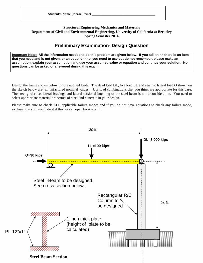
Preliminary Examination- Design Question Important Note: All the information needed to do this problem are given below. If you still think there is an item that you need and is not given, or an equation that you need to use but do not remember, please make an assumption, explain your assumption and use your assumed value or equation and continue your solution. No questions can be asked or answered during this exam. Design the frame shown below for the applied loads. The dead load DL, live load LL and seismic lateral load Q shown on the sketch below are all unfactored nominal values. Use load combinations that you think are appropriate for this case. The steel girder has lateral bracings and lateral-torsional buckling of the steel beam is not a consideration. You need to select appropriate material properties of steel and concrete in your design.
Please make sure to check ALL applicable failure modes and if you do not have equations to check any failure mode, explain how you would do it if this was an open book exam.
30 ft.
DL=3,000 kips
Rectangular R/C Column to be designed
LL=100 kips
24 ft.
Q=30 kips
Steel I-Beam to be designed. See cross section below.
1 inch thick plate (height of plate to be calculated) PL 12”x1”
University of California Department of Civil and Environmental Engineering Fall Semester 2013 Structural Engineering, Mechanics and Materials
Preliminary Examination
Structural Engineering Design
Some of the questions below are conceptual and open ended in nature. If you do not feel you have enough information to answer the question, you may make any reasonable assumption needed so long as you explain your thinking clearly. 1. Consider the seismic detailing of a weightless girder that is part of a reinforced
concrete moment resisting frame. The frame is to be designed to behave in a highly ductile manner, and may be subjected to earthquakes significantly (say 8 times) greater than it can withstand elastically. The girder is 30 feet long, and 30 inches deep.
For this problem, vertical gravity loads, and the effects of horizontal earthquake forces should be considered, but vertical earthquake effects should be ignored.
The figure to the right shows the nominal moment capacities of the girder at the ends and middle. The moments are based on nominal strengths of materials. Moments are shown on the face corresponding to yielding of the tension reinforcement on that side of the beam.
The vertical gravity load shown at the middle of the beam has already been adjusted to account for all code related load factors for combinations related to earthquake effects.
a. Conceptually describe (with sketches) the deformed shape of the member if plastic hinges form (i) only at the ends of the girder, or (ii) at other locations during lateral seismic displacement of the building?
b. Briefly describe why one might prefer to have plastic hinging only near the ends of the member.
c. For the specific beam shown, where do you expect the girder to form plastic hinges during a very large earthquake? Show calculations to justify your answer.
d. Based on these calculations, make sketches to illustrate how you would detail the member. That is, you do not need to compute specific bar sizes or dimensions, but just schematically indicate locations where you would place longitudinal reinforcement, and the basic type, location and detailing of transverse reinforcement along the girder.
e. Compute the maximum shear force that should be considered in the design of the girder? Where does this shear occur?
[If you believe you are not familiar enough with reinforced concrete to do this problem, you may consider the same problem but considering it to be constructed in steel. For part d, identify special detailing requirements that would be needed at various points along the beam.]
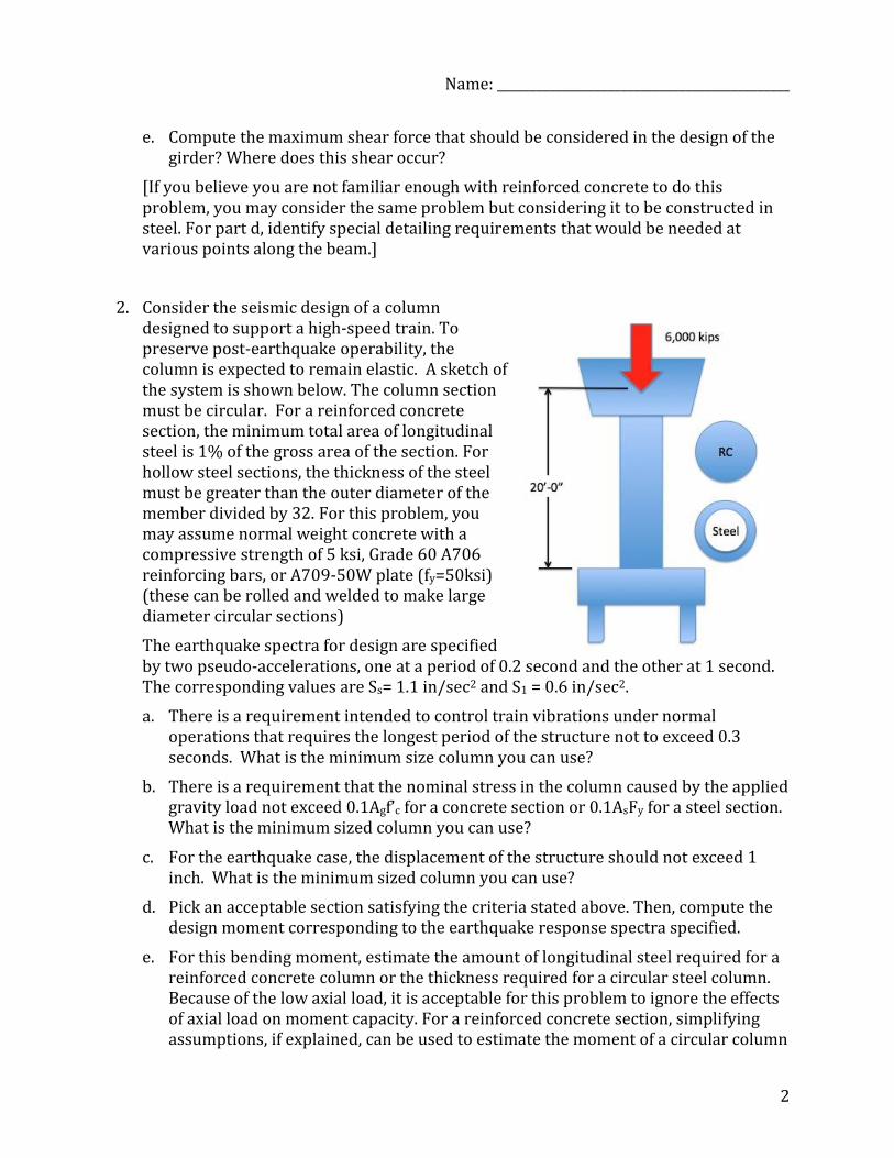
2. Consider the seismic design of a column designed to support a high-speed train. To preserve post-earthquake operability, the column is expected to remain elastic. A sketch of the system is shown below. The column section must be circular. For a reinforced concrete section, the minimum total area of longitudinal steel is 1% of the gross area of the section. For hollow steel sections, the thickness of the steel must be greater than the outer diameter of the member divided by 32. For this problem, you may assume normal weight concrete with a compressive strength of 5 ksi, Grade 60 A706 reinforcing bars, or A709-50W plate (fy=50ksi) (these can be rolled and welded to make large diameter circular sections)
The earthquake spectra for design are specified by two pseudo-accelerations, one at a period of 0.2 second and the other at 1 second. The corresponding values are Ss= 1.1 in/sec2 and S1 = 0.6 in/sec2.
a. There is a requirement intended to control train vibrations under normal operations that requires the longest period of the structure not to exceed 0.3 seconds. What is the minimum size column you can use?
b. There is a requirement that the nominal stress in the column caused by the applied gravity load not exceed 0.1Agf’c for a concrete section or 0.1AsFy for a steel section. What is the minimum sized column you can use?
c. For the earthquake case, the displacement of the structure should not exceed 1 inch. What is the minimum sized column you can use?
d. Pick an acceptable section satisfying the criteria stated above. Then, compute the design moment corresponding to the earthquake response spectra specified.
e. For this bending moment, estimate the amount of longitudinal steel required for a reinforced concrete column or the thickness required for a circular steel column. Because of the low axial load, it is acceptable for this problem to ignore the effects of axial load on moment capacity. For a reinforced concrete section, simplifying assumptions, if explained, can be used to estimate the moment of a circular column
having many distributed longitudinal reinforcing bars. Draw a sketch of your section showing the basic design features.
f. While the column is expected to remain elastic for this level of shaking, it is possible that larger earthquakes might occur. Thus, capacity design methods should be considered. Describe briefly how you would use capacity design concepts to compute other design forces and detail the column and foundation. These elements are not to be designed. Only explain how you would approach this problem, given the design of the column you have obtained in part e.
Reference: For a circular section in terms of the outer and inner RADII (Ro and Ri), the area is π(Ro2-Ri2), moment of inertia is π(Ro4-Ri4)/4, and plastic section modulus is π(Ro3-Ri3)/48.
University of California at Berkeley Structural Engineering Mechanics and Materials
Department of Civil and Environmental Engineering Fall Semester 2012
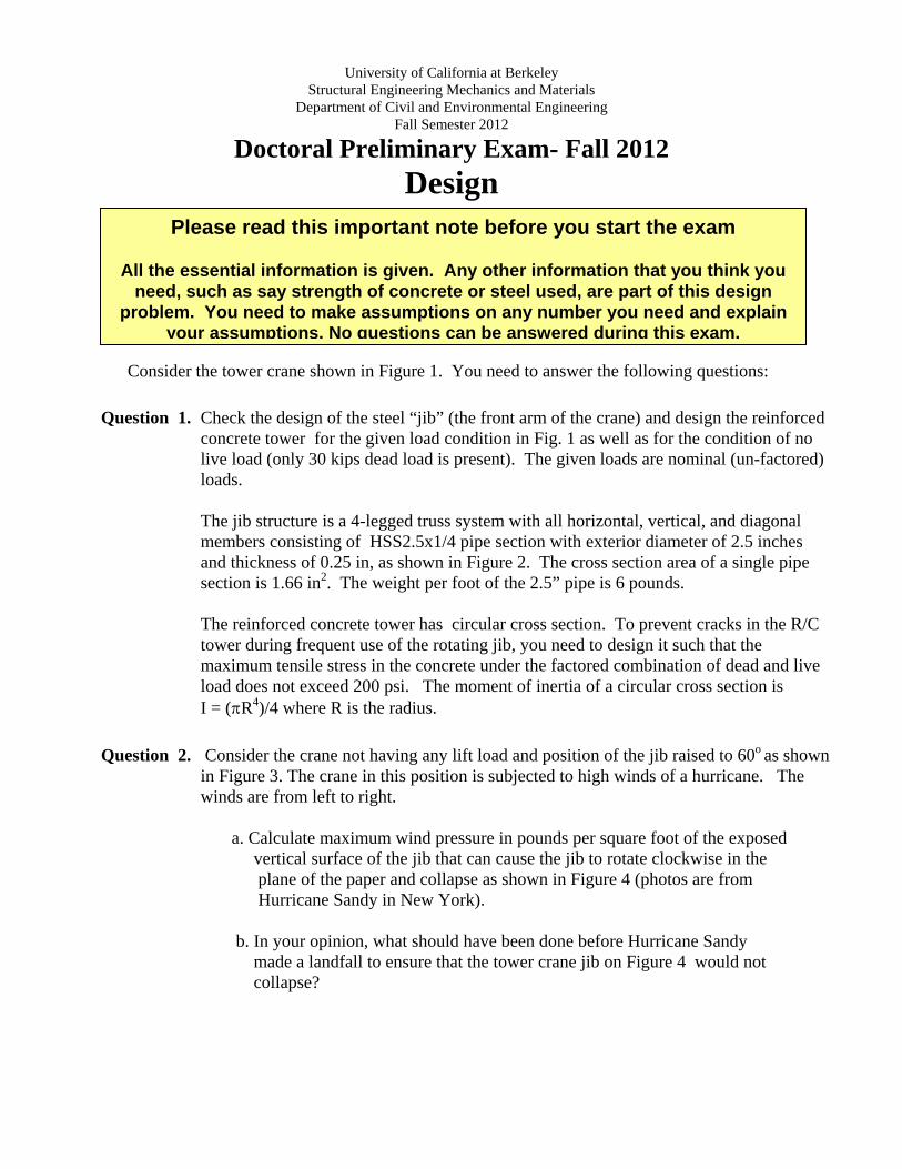
Doctoral Preliminary Exam- Fall 2012 Design
______________________________ Consider the tower crane shown in Figure 1. You need to answer the following questions:
Question 1. Check the design of the steel “jib” (the front arm of the crane) and design the reinforced concrete tower for the given load condition in Fig. 1 as well as for the condition of no live load (only 30 kips dead load is present). The given loads are nominal (un-factored) loads. The jib structure is a 4-legged truss system with all horizontal, vertical, and diagonal members consisting of HSS2.5x1/4 pipe section with exterior diameter of 2.5 inches and thickness of 0.25 in, as shown in Figure 2. The cross section area of a single pipe section is 1.66 in2. The weight per foot of the 2.5” pipe is 6 pounds. The reinforced concrete tower has circular cross section. To prevent cracks in the R/C tower during frequent use of the rotating jib, you need to design it such that the maximum tensile stress in the concrete under the factored combination of dead and live load does not exceed 200 psi. The moment of inertia of a circular cross section is I = (R4)/4 where R is the radius.
Question 2. Consider the crane not having any lift load and position of the jib raised to 60o as shown in Figure 3. The crane in this position is subjected to high winds of a hurricane. The winds are from left to right. a. Calculate maximum wind pressure in pounds per square foot of the exposed vertical surface of the jib that can cause the jib to rotate clockwise in the plane of the paper and collapse as shown in Figure 4 (photos are from Hurricane Sandy in New York). b. In your opinion, what should have been done before Hurricane Sandy made a landfall to ensure that the tower crane jib on Figure 4 would not collapse?
Please read this important note before you start the exam
All the essential information is given. Any other information that you think you need, such as say strength of concrete or steel used, are part of this design
problem. You need to make assumptions on any number you need and explain your assumptions. No questions can be answered during this exam.
Figure 1 for Question 1
10 ft.
65 ft.
60 ft.
30 kips
7 ft.
Steel Jib to be checked
R/C Tower to be designed
5 kips
Figure 2- Details of Steel Jib
All truss members are HSS2.5x1/4: Area=1.66 in2 External Diameter = 2.5 in. Thickness= 0.25 in. Fy= yield stress= 80 ksi Weight per foot= 6 pounds per foot