SITE DEVELOPMENT CONSIDERATIONS ........................................................... 14 Site Grading ...................................................................................................... 14 Buried Utilities ................................................................................................... 15 Underdrain Systems ......................................................................................... 16
FOUNDATION AND FLOOR SYSTEM CONCEPTS .............................................. 17
CLASSIC HOMES FOREST LAKES SUBDIVISION (FILINGS 5, 6 AND 7) CTL|T PROJECT NO. CS18916-105
TABLE OF CONTENTS – Page 2
REFERENCES
FIG. 1 – LOCATION OF EXPLORATORY BORINGS
FIG. 2 – SITE GEOLOGY
FIG. 3 – ENGINEERING GEOLOGIC CONSIDERATIONS
FIG. 4 – ALTERNATE 1 UNDERDRAIN TRENCH DETAILS
FIG. 5 – ALTERNATE 2 UNDERDRAIN TRENCH DETAILS
APPENDIX A – SUMMARY LOGS OF EXPLORATORY BORINGS
APPENDIX B – LABORATORY TEST RESULTS TABLE B-1: SUMMARY OF LABORATORY TESTING
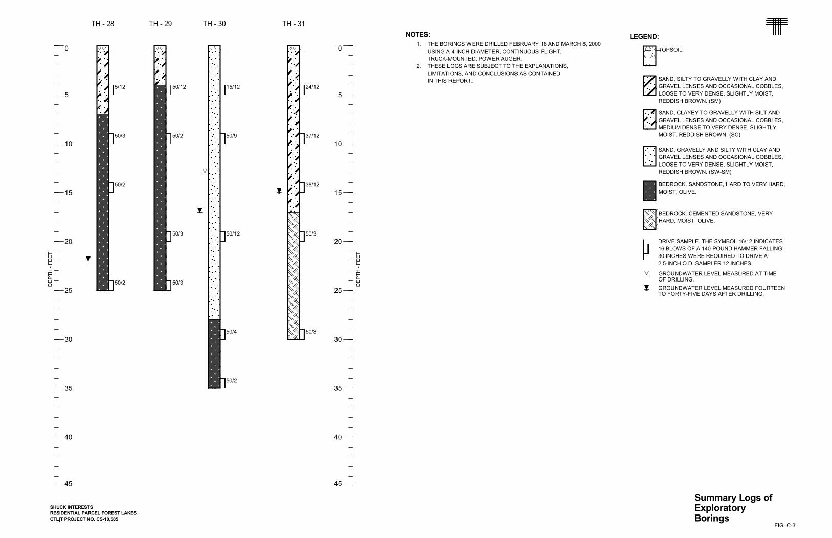
APPENDIX C – SUMMARY LOGS OF EXPLORATORY BORINGS (CTL|T JOB NO. CS-10,585; DATED AUGUST 15, 2001)
APPENDIX D – GUIDELINE SITE GRADING SPECIFICATIONS FOREST LAKES SUBDIVISION (FILINGS 5, 6 AND 7) EL PASO COUNTY, COLORADO
CLASSIC HOMES FOREST LAKES SUBDIVISION (FILINGS 5, 6 AND 7) CTL|T PROJECT NO. CS18916-105
1
SCOPE
This report presents the results of our Geologic Hazards Evaluation and Prelimi-
nary Geotechnical Investigation for Filings 5, 6 and 7 of the Forest Lakes Subdivision in
El Paso County, Colorado. The investigated parcel is planned for development of sin-
gle-family residential lots. Our purpose was to evaluate the parcel for the occurrence of
geologic hazards that may impact development of the property, and to provide prelimi-
nary geotechnical design concepts. This report includes a summary of subsurface and
groundwater conditions found in our exploratory borings, a description of our engineer-
ing analysis of the geologic conditions at the site, and our opinion of the potential influ-
ence of the geologic hazards on the planned structures and other site improvements. A
debris flow/mudflow analysis was prepared by our firm for Filings 5, 6 and 7 under a
separate cover. The scope of our services is described in our proposal (CS-18-0033)
dated March 29, 2018.
The report was prepared based on conditions interpreted from field reconnais-
sance of the site, conditions found in our exploratory borings, results of laboratory tests,
engineering analysis, and our experience. Observations made during grading or con-
struction may indicate conditions that require revision or re-evaluation of some of the
preliminary criteria presented in this report. The criteria presented are for the develop-
ment as described. Revision in the scope of the project could influence our recommen-
dations. If changes occur, we should review the development plans and the effect of the
changes on our preliminary design criteria. Evaluation of the property for the possible
presence of potentially hazardous materials (Environmental Site Assessment) was
beyond the scope of this investigation. Assessment of the site for the potential for wild-
fire hazards, corrosive soils, erosion problems, or flooding is also beyond the scope of
this investigation.
The following section summarizes the report. A more complete description of the
conditions found at the site, our interpretations, and our recommendations are included
in the report.
CLASSIC HOMES FOREST LAKES SUBDIVISION (FILINGS 5, 6 AND 7) CTL|T PROJECT NO. CS18916-105
2
SUMMARY
1. We did not identify geologic hazards that we anticipate will preclude de-velopment of the project as planned. The conditions we identified include shallow groundwater and potential for erosion, flooding and debris flow. Slopes within and near the development areas appear to be stable and the construction of the proposed single-family homes should not negative-ly impact slope stability. Collapsible soils were not identified in this study and given the particle size distribution and fines content of samples, would not be expected. Regional geologic conditions that impact the site include seismicity and radioactivity. We believe each of these conditions can be mitigated with engineering design and construction methods commonly employed in this area.
2. The near-surface soils encountered in the twenty-four exploratory borings drilled during this investigation and our 2001 study consisted of 4 feet to over 50 feet of natural, sand and gravel soils with occasional clay lenses. The near-surface soils were underlain by sandstone bedrock.
3. At the time of drilling, groundwater was encountered in eight of the explor-atory borings at depths of 8 to 26 feet below the existing ground surface. When water levels were checked again following the completion of drilling operations, water was measured in eleven of the borings at depths of 6 to 26 feet. The shallowest groundwater was encountered along North Beaver Creek. Groundwater levels will vary with seasonal precipitation and land-scaping irrigation.
4. In our opinion, site grading and utility installation across the site can be accomplished using conventional, heavy-duty construction equipment.
5. We anticipate spread footing foundations and slab-on-grade floors will be appropriate for the dwellings constructed at this site. Some of the soil and bedrock may be expansive when wetted. If expansive soil and/or bedrock occurs, sub-excavation of a zone of expansive material from beneath spread footing foundations and reworking the soil as low-swelling, mois-ture-conditioned fill may be appropriate. Our widely-spaced borings and laboratory test results suggest most of the residential sites can be devel-oped successfully using shallow foundations and slab-on-grade basement floors without soil improvement.
6. Irrigation of landscaping should be minimized to reduce problems associ-ated with expansive soils. Overall plans should provide for the rapid con-veyance of surface runoff to the storm sewer system and centralized drainage channels.
CLASSIC HOMES FOREST LAKES SUBDIVISION (FILINGS 5, 6 AND 7) CTL|T PROJECT NO. CS18916-105
3
SITE CONDITIONS
The investigated parcel of land is situated west of the intersection of Forest
Lakes Drive and Mesa Top Drive (portions of Sections 28 and 29, Township 11 South,
Range 67 West of the 6th Principal Meridian), El Paso County, Colorado. The revised,
overall development plan (dated November 30, 2018) is shown in Fig. 1.
Filings 5, 6 and 7 are situated within a broad valley between two east-to-west
trending ridges. The ground surface within the portion of the parcel that is to be devel-
oped with single-family, residential housing generally slopes downward to the east and
southeast at grades of between about 5 and 10 percent. A local mesa dominates the
western portion of the parcel. The sides of the mesa are considerably steeper and will
not be disturbed during development of the subdivision. Beaver Creek and North Bea-
ver Creek converge in the eastern third of the property. Vegetation on the site consists
of mostly grasses, weeds, pine trees, scrub oak, and deciduous trees and bushes. The
property is currently being used as pastureland for cattle. The land to the north and
south of the parcel is developed with widely-spaced, single-family residences. Phase 1
of the subdivision is situated to the east.
PROPOSED DEVELOPMENT
We understand the parcel is to be developed with single-family, residential dwell-
ing lots. Paved access roads will be constructed in association with the planned devel-
opment. We anticipate the residences will be one and two-story, wood-frame structures
with basement areas and attached, multi-automobile garages. We anticipate the dwell-
ings will be serviced by a centralized sanitary sewer collection system and potable wa-
ter distribution system.
PREVIOUS INVESTIGATION
Our firm prepared a Geologic Hazards Evaluation and Preliminary Geotechnical
Investigation for the Forest Lakes Master Development Plan (Job No. CS-10,585; report
dated August 15, 2001) that included the parcel presented in this study. Thirty-nine
CLASSIC HOMES FOREST LAKES SUBDIVISION (FILINGS 5, 6 AND 7) CTL|T PROJECT NO. CS18916-105
4
exploratory borings were drilled in association with the 2001 investigation. Fourteen of
the borings were located within the boundaries of Filings 5, 6 and 7 and were reviewed
as part of this study. Subsurface conditions encountered in the earlier borings were
similar to the materials found in the ten borings drilled during this investigation.
SUBSURFACE INVESTIGATION
Subsurface conditions at the site were investigated by drilling ten supplemental
exploratory borings (TH-101 through TH-110) and reviewing the subsurface conditions
found in fourteen borings drilled during our 2001 study. The locations of the twenty-four
borings are shown in Fig. 1. Graphical logs of the conditions found in our recent ex-
ploratory borings, the results of field penetration resistance tests, and some laboratory
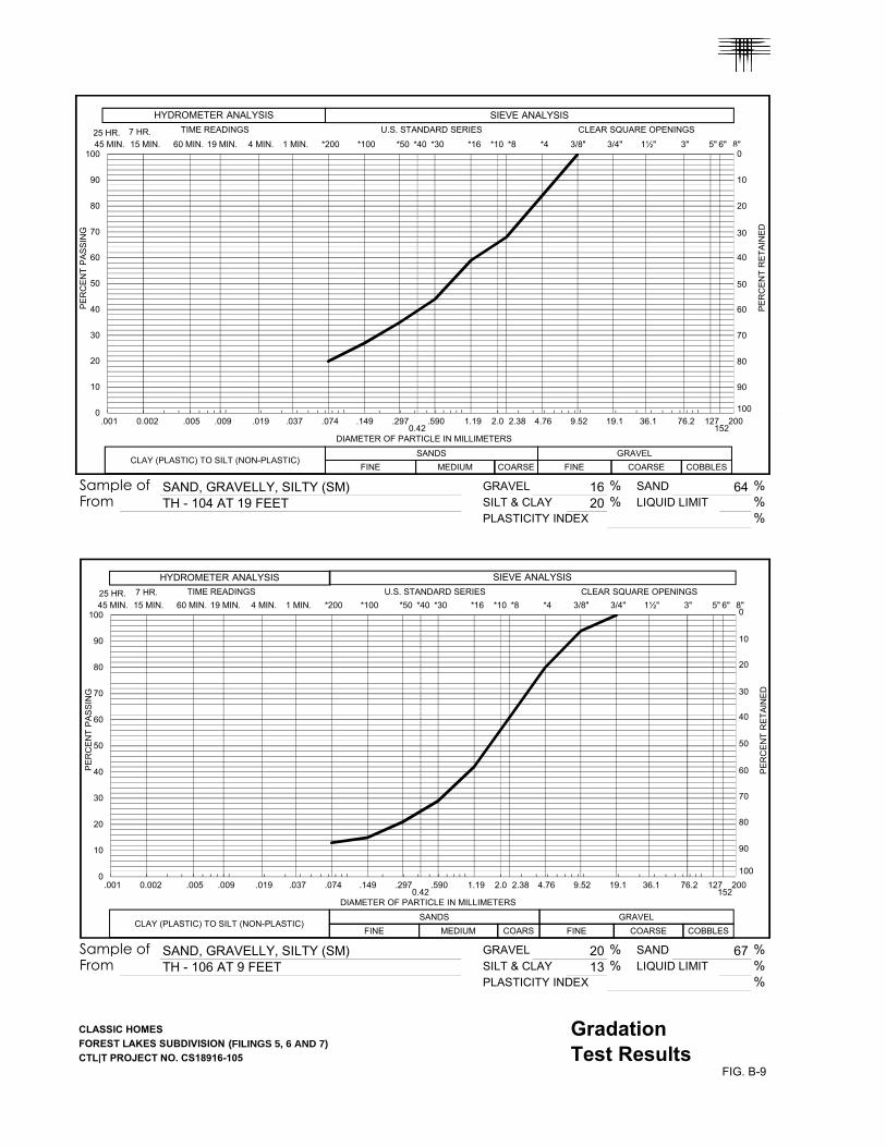
data are presented in Appendix A. Swell-consolidation and gradation test results are
presented in Appendix B. Laboratory test data are summarized in Table B-1. Graphical
logs of the borings drilled during the 2001 study, the results of field penetration re-
sistance tests, and some laboratory data are presented in Appendix C.
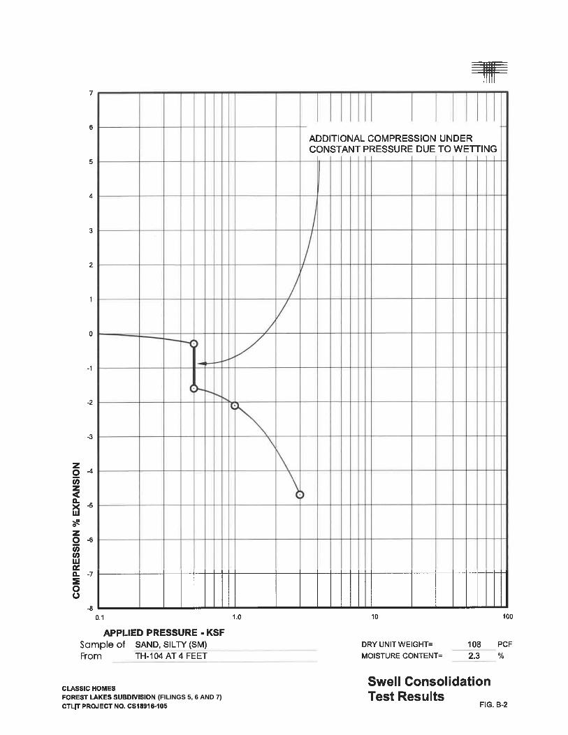
Soil and bedrock samples obtained during this study were returned to our labora-
tory and visually classified. Laboratory testing was then assigned to representative
samples. Testing included moisture content and dry density, swell-consolidation, grada-
tion analysis, and water-soluble sulfate content tests. The swell test samples were wet-
ted under an applied pressure that approximated the overburden pressure (the weight
of overlying soil and bedrock).
SUBSURFACE CONDITIONS
The near-surface soils encountered in the twenty-four exploratory borings drilled
during this investigation and our 2001 study consisted of 4 feet to over 50 feet of natu-
ral, sand and gravel soils with occasional clay lenses. The near-surface soils were un-
derlain by sandstone bedrock. Some of the pertinent engineering characteristics of the
soils and bedrock encountered and groundwater conditions are discussed in the follow-
ing paragraphs.
CLASSIC HOMES FOREST LAKES SUBDIVISION (FILINGS 5, 6 AND 7) CTL|T PROJECT NO. CS18916-105
5
Natural Sands and Gravels
The predominant soils encountered at the ground surface in each of the borings
consisted of clean to silty or clayey to very clayey sand with variable amounts of gravel.
Layers of very sandy, slightly silty to silty gravel with cobbles were found to be interbed-
ded with the predominant sands. The granular soil layer encountered in the borings
extended to depths of 4 feet to over 50 feet below the existing ground surface. The sand
was medium dense to very dense and the gravel was dense to very dense based on the
results of field penetration resistance tests. Occasional layers of sandy to very sandy
clay were found to be interbedded with the predominant sand. Samples of the sand and
gravel tested in our laboratory contained 4 to 37 percent clay and silt-sized particles
(passing the No. 200 sieve). The sampling device eliminated any particles greater than
about 1-1/2 inches in diameter. Our experience indicates the sands are non-expansive
or exhibit generally low measured swell values when wetted. Two samples of the very
clayey sand that were subjected to swell-consolidation testing exhibited low measured
swell values of 0.1 and 1.1 percent when wetted. Based on the particle size distribu-
tions, the silt and clay fines contents, and the natural dry densities of the samples, the
compression behavior of the sand samples is believed to be the result of sample dis-
turbance and is not representative of a material that is prone to collapse.
Bedrock
Silty sandstone bedrock was encountered in all but three of the borings, underly-
ing the near-surface soils, at depths of 4 to 29 feet below the existing ground surface.
The bedrock was hard to very hard based on the results of field penetration resistance
tests and was poorly to well-cemented. Three samples of the sandstone subjected to
swell-consolidation testing exhibited low measured swell values of 0 to 0.4 percent
when wetted. Samples of the sandstone tested in our laboratory contained 22 to 49
percent clay and silt-sized particles (passing the No. 200 sieve).
Groundwater
At the time of drilling, groundwater was encountered in eight of the exploratory
borings at depths of 8 to 26 feet below the existing ground surface. When water levels
CLASSIC HOMES FOREST LAKES SUBDIVISION (FILINGS 5, 6 AND 7) CTL|T PROJECT NO. CS18916-105
6
were checked again following the completion of drilling operations, water was measured
in eleven of the borings at depths of 6 to 26 feet. The shallowest groundwater was en-
countered along North Beaver Creek. Groundwater levels will vary with seasonal precip-
itation and landscaping irrigation.
SITE GEOLOGY
Geologic conditions for Forest Lakes (Filings 5, 6 and 7) were evaluated through
the review of published geologic maps, field reconnaissance, and exploratory borings.
As discussed earlier, our Project No. CS-10,585 included Filings 5, 6 and 7. Our report
dated August 15, 2001 was reviewed and is updated for this current study. Information
from these sources was used to produce our interpretation of site geology (Fig. 2). A list
of references is included at the end of this report.
The planned, single-family residential development shown in Fig. 1 is situated
generally on uplands west of the confluence of North Beaver Creek and Beaver Creek.
Slopes within proposed development areas are typically gentle to moderate to the east.
A local mesa dominates the west portion of the parcel and contains steeper slopes that
will not be developed. The North Beaver Creek drainage gradient flattens along the
north border of the parcel. Past floods have left abandoned channels and debris depos-
its. The main Beaver Creek channel along the south side is at a lower slope, is more
defined, and shows less evidence for geologically recent overbank flows. The parcel
has been used for agriculture in the past. An excerpt of the 1994 USGS topographic
map of the Palmer Lake Quadrangle is reproduced below, with the project area outlined
in red.
CLASSIC HOMES FOREST LAKES SUBDIVISION (FILINGS 5, 6 AND 7) CTL|T PROJECT NO. CS18916-105
7
Excerpt from 1994 USGS Topographic Map of the Palmer Lake Quadrangle.
Excerpt from June 2017 Google Earth aerial photography showing the Filings 5, 6 and 7 development area. Note man-made pits just west of the confluence of North Beaver and Beaver Creek.
The locality is at the foot of the Front Range of the Rocky Mountains, less than
½-mile east of the Rampart Range Fault, an inactive reverse fault that places Pre-
Cambrian crystalline metamorphic and igneous rocks against much younger sedimen-
tary rocks of the Late Cretaceous and Eocene Dawson Formation, which underlie the
subject site. Geologic processes of the last several million years have carved drainages
and divides, leaving alluvial fan and colluvial-slopewash deposits chiefly composed of
sand and gravel. An excerpt from the 2007 “Geologic Map of the Palmer Lake Quad-
rangle” by Colorado Geological Survey is presented below.
CLASSIC HOMES FOREST LAKES SUBDIVISION (FILINGS 5, 6 AND 7) CTL|T PROJECT NO. CS18916-105
8
Most of the site contains 4 to more than 50 feet of medium dense to very dense,
reddish sand and gravel alluvial soil over hard to cemented sandstone bedrock. Hill
slopes on the lone mesa and along the Beaver Creeks may expose slopewash colluvi-
um over bedrock. Bedrock is from the Eocene-aged Facies Unit 3 of the Dawson For-
mation, dominated by poorly to well-cemented sandstone. Although our borings did not
encounter any, claystone may be present. The poorly-cemented sandstone is easily
erodible. The material readily weathers into residual soil. The following sections discuss
the mapped units.
Excerpt from the 2007 “Geologic Map of the Palmer Lake Quadrangle” by Colorado Geological Survey. Site area shown outlined in red. Our field observations generally concur with CGS’ mapping. Our borings show the Dawson Formation (Map Symbol TKda3) is overlain by 4 to more than 50 feet of slopewash colluvium or stream alluvium.
Surficial Deposits
Our borings encountered 4 to more than 50 feet of silty and clayey sand and
gravel soil. We believe that for the purposes of engineering geologic evaluation of this
site, the surficial soils can be considered as being Alluvial Fan (Map Units Qaf1, Qaf2,
and Qg1, Qg2 and Qg3) or Slopewash Colluvium (Map Unit Qc). These soils are geolog-
ically-recent, Pleistocene and Holocene-age. The dominant stratum is reddish-brown,
silty and clayey sand with gravel in the Qaf2 alluvial fan deposit. This stable, middle fan
is persistent in the region and has been eroded by North and South Beaver Creeks.
Their younger active alluvial fans are mapped as Qaf1. The areas mapped as Qaf1 con-
CLASSIC HOMES FOREST LAKES SUBDIVISION (FILINGS 5, 6 AND 7) CTL|T PROJECT NO. CS18916-105
9
tain scattered cobble-boulder fields from debris flow events in the geologically recent
past. Where North Beaver Creek passes along the north border and into the north por-
tion of the property, the Qaf1 area exhibits eroded, active and abandoned channels
typical of geologically recent flows. Older, higher Quaternary gravel fans are off the
parcel to the north and south. An isolated remnant covers the mesa on the west part of
the parcel. Colluvium (Qc) forms on the hillsides and between terraces due to slope-
wash and gravity and is similar to the alluvial soils, but may contain clay from residual
weathering of the underlying Dawson Formation.
Our previous report in 2001 described an ancient landslide east of the Rampart
Fault that may have encroached on the west border of the site. Indeed, our borings TH-
25 (from 2001) and TH-102 from the current study encountered about 20 or more feet
more soil than nearby boreholes, but the soil was similar to that encountered in other
parts of the Qaf2 fan deposit, rather than material that might be expected with an an-
cient landslide in the Dawson Formation. The current CGS map shows the area as Qc3,
old colluvium with remnant or lag boulder deposits. The off-site slopes appear stable
and are probably underlain at relatively shallow depth by the Dawson Formation, weak-
ly-cemented sandstone.
Bedrock
Below soil, we encountered firm to very hard, poorly to well-cemented sandstone
bedrock from the Eocene-age Facies Unit 3 of the Dawson Formation (Map Symbol
TKda3). Exposures were not visible, but available literature suggests the Dawson For-
mation exhibits a gentle dip toward the east.
GEOLOGIC HAZARDS AND ENGINEERING CONSTRAINTS
Colorado Geological Survey prepared their review comments for the Forest
Lakes Phase II PUD Amendment and Preliminary Plan in a letter dated February 6,
2018. They asked for an update of our 2001 investigation and to address debris flow
and debris flood, shallow groundwater, collapsible soils, potentially unstable slopes, and
erosion hazards to the Phase II lots. These are discussed in this section.
CLASSIC HOMES FOREST LAKES SUBDIVISION (FILINGS 5, 6 AND 7) CTL|T PROJECT NO. CS18916-105
10
We did not identify geologic hazards that we believe will preclude development of
the project as planned. The conditions we identified include shallow groundwater and
potential for erosion, flood and debris flow. Slopes within and near development areas
appear to be stable and the development of homes should not negatively impact slope
stability. Collapsible soils were not identified in this study and given the particle size
distribution and fines content of samples, would not be expected. Regional geologic
conditions that impact the site include seismicity and radioactivity. These issues do not
pose hazards or constraints to development if avoided or mitigated using normally em-
ployed methods. We believe each of these conditions can be mitigated with engineering
design and construction methods commonly employed in this area. These conditions
are discussed in greater detail in the sections that follow.
Engineering Geologic Mapping
The engineering geology classification from Robinson (1977) was considered
and areas were mapped as described below and shown in Fig. 3. The other issues are
site-wide concerns and are not depicted in Fig. 3.
Map Unit “2A” depicts stable alluvium, colluvium and bedrock on gentle to moder-
ate slopes of 5 to 12 percent. Most of the lots surrounding the lone mesa lie in ar-
eas within this classification. These areas are low risk for problems due to geolog-
ic hazards.
Map Unit “3B” depicts expansive and potentially expansive soil and bedrock on
flat to moderate slopes of 0 to 12 percent. Some lots along the north border of the
property and in the eastern portion of the site lie within this classification. Our bor-
ings revealed expansive soil and bedrock risk is nil or low over the site. These ar-
eas are low risk for problems due to geologic hazards.
Map Unit “4A” depicts potentially unstable colluvium and bedrock on moderate to
steep slopes of 12 to 24 percent. These areas are on the lone mesa and other
site locations and are avoided for the current development plan. The mesa
hillslope did not exhibit signs of instability.
CLASSIC HOMES FOREST LAKES SUBDIVISION (FILINGS 5, 6 AND 7) CTL|T PROJECT NO. CS18916-105
11
Map Unit “7A” depicts physiographic flood plain where erosion and deposition
presently occur and is generally subject to recurrent flooding. Site evidence sug-
gests debris flow risk along the northeast side of the lone mesa. Some planned
lots lie within the area we believe may be in active flood plains. Mitigation can
consist of avoidance or channel improvements to convey the design flow.
Expansive Soil and Bedrock
Site soils are predominantly silty and clayey sand with gravel with less than 30
percent fines. Swell potential in a few cohesive samples was about 1 percent or less,
which is considered low. Weakly to well-cemented sandstone bedrock was found in our
borings. Site soils and bedrock are expected to be predominantly non-expansive. Some
of the soil and bedrock may be expansive when wetted. Issues associated with the
expansive soil and bedrock can be mitigated through engineered foundations and floor
systems, possibly in conjunction with ground modification such as sub-excavation and
reworking the soil as low-swelling, moisture-conditioned fill. Current data implies most
sites will be able to successfully use shallow foundations and slab-on-grade basement
floors without soil improvement.
Flood, Debris Flow and Erosion
Site evidence for flooding and debris flow has been observed by our personnel
and others, particularly along North Beaver Creek adjacent to the lone mesa. Concur-
rent to this Geologic Hazards Evaluation and Preliminary Geotechnical Investigation,
CTL|Thompson, Inc. performed analyses of the potential for flooding, debris flow, and
mudflow along the drainageways of North Beaver Creek, South Beaver Creek, Hell
Creek, and Beaver Creek. A discussion of our observations and methodology, as well
as our opinions and recommendations, are presented in a separate report.
The subject parcel contains drainages that are subject to flooding and that exhibit
moderate to steep slopes. Site soils are sandy and susceptible to the effects of erosion.
Maintaining vegetative cover and providing engineered surface drainage will reduce the
potential for erosion. The project Civil Engineer should design the site to arrest
downcutting and prevent flood damage to improvements.
CLASSIC HOMES FOREST LAKES SUBDIVISION (FILINGS 5, 6 AND 7) CTL|T PROJECT NO. CS18916-105
12
Shallow Groundwater
We noted groundwater was shallow (depths of 6 to 7.5 feet) in four of our borings
(TH-105, 107, 108 and 109) located along the north fork of Beaver Creek. Other areas
of the site have groundwater depths exceeding about 15 feet. Mitigation for groundwater
usually consists of raising grades or keeping basements at least 3 and preferably 5 feet
above the water. To the extent channel improvements in Beaver Creek lower the eleva-
tion, it is possible the groundwater level will drop as well.
Collapsible Soils
Our 2001 report had a few loose sand samples at a 4-foot depth and described
compression of up to 7 percent under conditions of loading and wetting. Our current
study found no loose sand samples and of the few samples that were fine enough to
test, very little compression was noted. We tested three samples to evaluate their Atter-
berg Limits and found two to be non-plastic and one had a Plasticity Index of 11 with 37
percent silt and clay fines. The site soils are not expected to be collapsible because of
their particle size gradation (they have significant gravel and low fines content) and high
in-place density. We believe the compression potential measured in a few samples in
2001 is due to the extreme difficulty in preparing granular specimens for testing that
represent the actual soil matrix condition.
Unstable Slopes
Other than a few steeply-eroded stream banks outside planned development ar-
eas, there appear to be no unstable, steep slopes that affect development.
Economic Minerals and Underground Mines
While the site does contain sand and gravel deposits, we doubt permitting for
mining of the material is feasible, considering the surrounding land uses. Energy fuels
such as uranium, oil and gas may or not be present. Two oil and gas prospect wells are
mapped by CGS less than ½-mile southwest of the site. We do not know the status of
these wells. No record of underground mining was encountered.
CLASSIC HOMES FOREST LAKES SUBDIVISION (FILINGS 5, 6 AND 7) CTL|T PROJECT NO. CS18916-105
13
Seismicity
This area, like most of central Colorado, is subject to a degree of seismic activity.
Geologic evidence indicates that movement along some Front Range faults has oc-
curred during the last two million years (Quaternary). This includes the Rampart Range
Fault, which is located less than a half mile west of the site. We believe the soils on the
property classify as Site Class D (stiff soil profile) according to the 2015 International
Building Code (2015 IBC).
Radon and Radioactivity
We believe no unusual hazard exists from naturally occurring sources of radioac-
tivity on this site. However, the materials found in our borings can be associated with
the production of radon gas and concentrations in excess of EPA guidelines can occur.
Radon tends to collect in below-grade, residential areas due to limited outside air ex-
change and interior ventilation. Passive and active mitigation procedures are commonly
employed in this region to effectively reduce the buildup of radon gas. Measures that
can be taken after a structure is enclosed during construction include installing a blower
connected to the foundation drain (if present) and sealing the joints and cracks in con-
crete floors and foundation walls. If the occurrence of radon is a concern, we recom-
mend the structures be tested after they are enclosed, and mitigation systems installed
to reduce the risk.
Low-level gamma radiation levels were measured in the cuttings from our explor-
atory borings using a LUDLUM Micro R Meter (Model 19). The meter provides readings
of low-level gamma radiation in terms of micro R/Hr (micro Roentgens per hour). Back-
ground readings ranged between 18 and 21 micro R/Hr. Readings on the drill cuttings
ranged between 18 and 21 micro R/Hr. The “background” level of low-level gamma
radiation in this area generally ranges from 15 to 20 micro R/Hr with the level of concern
being established at about twice background. This would imply remediation should be
performed for materials which exceed about 30 to 40 micro R/Hr at this site. Our read-
ings were lower than the action level.
CLASSIC HOMES FOREST LAKES SUBDIVISION (FILINGS 5, 6 AND 7) CTL|T PROJECT NO. CS18916-105
14
SITE DEVELOPMENT CONSIDERATIONS
From an engineering point-of-view, the more significant conditions impacting
construction are the occurrence of shallow groundwater and potential for erosion, flood-
ing and debris flow. The following sections discuss the impact of these conditions on
development and possible methods of mitigation.
Site Grading
No grading plans were available for our review at the time of this study. We antic-
ipate comparatively shallow cuts and fills (less than 10 feet) will be necessary to
achieve the desired building pad elevations for most of the area that will be developed.
The presence of shallow, hard to very hard, sandstone bedrock in the southwestern
portion of the site may influence basement excavation and construction of utility lines.
The sandstone is this area appears to be generally poorly cemented. We believe site
grading can likely be accomplished using conventional, heavy-duty earthmoving equip-
ment. We recommend grading plans consider long-term cut and fill slopes no steeper
than 3:1 (horizontal to vertical). This ratio considers that no seepage of groundwater
occurs. If groundwater seepage does occur, a drain system and flatter slopes may be
appropriate.
Comparatively shallow groundwater (less than 10 feet below the existing ground
surface) was encountered along North Beaver Creek. We recommend site grading cuts
be limited in this area and that final grades be raised as much as possible to reduce the
impact of the groundwater on basement construction and utility installation.
On-site evidence of flooding and debris flow has been observed, particularly
along the north fork of Beaver Creek adjacent to the mesa. A combination of channel
improvements and energy dissipation structures with debris storage capacity may be
needed to allow development of the planned homes along Beaver Creek. These topics
are discussed in more detail in our debris flow/mudflow analysis report. The project Civil
Engineer will need to consider these issues when preparing development design plans.
CLASSIC HOMES FOREST LAKES SUBDIVISION (FILINGS 5, 6 AND 7) CTL|T PROJECT NO. CS18916-105
15
Vegetation and organic materials should be removed from the ground surface in
areas to be filled. Soft or loose soils, if encountered, should be stabilized or removed to
stable material prior to placement of fill. Organic soils should be wasted in landscaping
areas. If insufficient landscaping areas are planned, topsoil can be mixed with clean fill
soils at a ratio of 15:1 (fill:topsoil) and placed as fill deeper than 8 feet below final grade.
Where the natural slopes are steeper than 20 percent (5:1, horizontal to vertical)
and fill is to be placed, horizontal benches must be cut into the hillside prior to fill
placement. The benches must be at least 12 feet wide or 1-1/2 times the width of the
compaction equipment and be provided at a vertical spacing of not more than 5 feet
(minimum of two benches). Larger bench widths may be required.
The ground surface in areas to receive fill should be scarified, moisture condi-
tioned and compacted. The properties of the fill will affect the performance of founda-
tions, slabs-on-grade, and pavements. We recommend grading fill composed of the on-
site sands and sandstone be placed in thin, loose lifts, moisture conditioned to within 2
percent of optimum moisture content, and compacted to at least 95 percent of maximum
modified Proctor dry density (ASTM D 1557). Natural clay and claystone incorporated in
grading fills should be placed at high moisture content to help mitigate potential swell.
Clay and claystone fill should be moisture conditioned to between 1 and 4 percent
above optimum moisture content and compacted in thin, loose lifts to at least 95 percent
of maximum standard Proctor dry density (ASTM D 698). Placement and compaction of
the grading fill should be observed and tested by our representative during construction.
Guideline specifications for site grading are presented in Appendix C.
Buried Utilities
Over most of the site, we believe utility trench excavation can be accomplished
using heavy-duty track hoes. The bedrock encountered in our borings was medium hard
to very hard, but predominantly poorly cemented. The bedrock formation could include
some layers of somewhat more cemented materials. Rock buckets and rock teeth may
be needed where utility excavations extend well into the bedrock formation and the
CLASSIC HOMES FOREST LAKES SUBDIVISION (FILINGS 5, 6 AND 7) CTL|T PROJECT NO. CS18916-105
16
bedrock is cemented. Utility contractors should be made aware of this possibility and
anticipate slower rates of pipeline installation in the very hard bedrock.
Excavations for utilities should be braced or sloped to maintain stability and
should meet applicable local, state, and federal safety regulations. The contractor
should identify the soils encountered in trench excavations and refer to Occupational
Safety and Health Administration (OSHA) standards to determine appropriate slopes.
We anticipate the near-surface sand soils and grading fill, and bedrock will classify as
Type C and Type B materials, respectively. Temporary excavations in Type C and Type
B materials require a maximum slope inclination of 1.5:1 and 1:1 (horizontal to vertical),
respectively, unless the excavation is shored or braced. Where groundwater seepage
occurs, flatter slopes will likely be required. Excavations deeper than 20 feet should be
designed by a professional engineer.
Water and sewer lines are usually constructed beneath paved roads. Compac-
tion of trench backfill will have a significant effect on the life and serviceability of pave-
ments. We recommend trench backfill be moisture conditioned and compacted in ac-
cordance with El Paso County specifications. Personnel from our firm should observe
and test the placement and compaction of the trench backfill during construction.
Underdrain Systems
Underdrains incorporated into the design of sanitary sewer systems can provide
a positive gravity outlet for individual, below-grade foundation drains, if desired. Where
no groundwater is encountered in sanitary sewer excavations, “passive” underdrains
may be used. The drain pipe should consist of smooth wall, rigid PVC pipe placed at a
minimum slope of 0.5 percent. An “active” section of smooth, perforated or slotted, rigid
PVC pipe should be placed for a minimum distance of one pipe length downstream of
manholes. The perforated pipe should be encased in at least 6 inches of free-draining
gravel, separated from the surrounding trench backfill by geotextile fabric. Seepage
collars should be constructed at the manhole locations to force water flowing through
pipe bedding into the underdrain. The seepage collars can be constructed of concrete
or clay.
CLASSIC HOMES FOREST LAKES SUBDIVISION (FILINGS 5, 6 AND 7) CTL|T PROJECT NO. CS18916-105
17
If high moisture conditions or groundwater is encountered in the sanitary sewer
trench, we recommend an active underdrain system with perforated or slotted pipe for
these areas. Active underdrains could help to lower the shallow groundwater elevation
found in portions of the development. A cutoff collar should be constructed around the
sewer pipe and underdrain pipe immediately downstream of the point where the under-
drain pipe exits the sewer trench or changes from active to passive. Solid pipe should
be used down-gradient of this cutoff collar to the point of discharge. The underdrain
should be maintained at least 3 to 5 feet below the lowest nearby foundation elevation.
Conceptual drain details are presented in Figs. 4 and 5.
As-built plans for the underdrain system should be prepared including location,
elevations, and cleanouts. The entity responsible for maintenance of the underdrain
system should retain the as-built plans for future reference.
FOUNDATION AND FLOOR SYSTEM CONCEPTS
We anticipate spread footing foundations and slab-on-grade floors will be appro-
priate for the dwellings constructed at this site. Some of the soil and bedrock may be
somewhat expansive when wetted. If expansive soil and/or bedrock occurs, sub-
excavation of a zone of the expansive material from beneath spread footing foundations
and reworking the soil as low-swelling, moisture-conditioned fill may be appropriate.
This approach should allow for the installation of spread footing foundations, possibly
designed utilizing a minimum deadload, and slab-on-grade basement floors. The results
of our widely-spaced borings and laboratory testing suggest most of the residences
within Filings 5, 6 and 7 will be able to be constructed using shallow foundations and
slab-on-grade basement floors without soil improvement being necessary. Soils and
foundation investigation reports prepared after completion of site grading should ad-
dress appropriate foundation systems and floor system alternatives on a lot-by-lot basis.
PAVEMENTS
Natural sands, sandstone, and granular grading fill are expected to be the pre-
dominant pavement subgrade materials. These materials exhibit generally good sub-
CLASSIC HOMES FOREST LAKES SUBDIVISION (FILINGS 5, 6 AND 7) CTL|T PROJECT NO. CS18916-105
18
grade support for pavements. Sandy clay and/or claystone bedrock may be encoun-
tered at pavement subgrade elevations in some areas. From a pavement standpoint,
the clay and claystone provide poor subgrade support characteristics, compared to the
granular, natural soils, sandstone, and grading fill. Pavements supported by expansive
clay materials will likely require thicker sections. The clayey subgrade soils could be
removed to a depth of approximately 2 feet beneath pavements and replaced with
granular soils. For the granular materials, we anticipate composite asphalt concrete and
aggregate base course pavement sections on the order of 4 inches of asphalt over 6 to
7 inches of base course may be needed for the local streets. This pavement thickness
may not be sufficient for construction traffic and some maintenance and repair work
may be needed prior to completion of the project. A subgrade investigation and pave-
ment design should be performed after site grading and utility installation are complete.
CONCRETE
Concrete in contact with soils can be subject to sulfate attack. We measured the
water-soluble sulfate concentration in three samples from the site at less than 0.1 per-
cent. Sulfate concentrations of less than 0.1 percent indicate Class 0 exposure to sul-
fate attack for concrete in contact with the subsoils, according to ACI 201.2R-01, as
published in the 2008 American Concrete Institute (ACI) Manual of Concrete Practice.
For this level of sulfate concentration, the ACI indicates Type I cement can be used for
concrete in contact with the subsoils. Superficial damage may occur to the exposed
surfaces of highly permeable concrete, even though sulfate levels are relatively low. To
control this risk and to resist freeze-thaw deterioration, the water-to-cementitious mate-
rial ratio should not exceed 0.50 for concrete in contact with soils that are likely to stay
moist due to surface drainage or high water tables. Concrete subjected to freeze-thaw
cycles should be air entrained.
SURFACE DRAINAGE AND IRRIGATION
The performance of structures, flatwork, and roads within the subdivision will be
influenced by surface drainage. When developing an overall drainage scheme, consid-
eration should be given to drainage around each structure and pavement area. Drain-
CLASSIC HOMES FOREST LAKES SUBDIVISION (FILINGS 5, 6 AND 7) CTL|T PROJECT NO. CS18916-105
19
age should be planned such that surface runoff is directed away from foundations and is
not allowed to pond adjacent to or between residences or over pavements. Ideally,
slopes of at least 6 inches in the first 10 feet should be planned for the areas surround-
ing the houses, where possible. Roof downspouts and other water collection systems
should discharge well beyond the limits of all backfill around the structures. Proper
control of surface runoff is also important to prevent the erosion of surface soils. Con-
centrated flows should not be directed over unprotected slopes. Permanent overlot
slopes should be seeded or mulched to reduce the potential for erosion. Backfill soils
behind the curb and gutter adjacent to streets and in utility trenches within individual lots
should be compacted. If surface drainage between preliminary development and con-
struction phases is neglected, performance of the roadways, flatwork, and foundations
may be compromised.
RECOMMENDED FUTURE INVESTIGATIONS
Based on the results of this study, we recommend the following investigations
and services be provided by our firm:
1. Construction materials testing and observation services during site devel-opment and construction.
2. Individual lot Soils and Foundation Investigations for foundation design.
3. Subgrade Investigation and Pavement Design for on-site pavements.
LIMITATIONS
The recommendations and conclusions presented in this report were prepared
based on conditions disclosed by our exploratory borings, geologic reconnaissance,
engineering analyses, and our experience. Variations in the subsurface conditions not
indicated by the borings are possible and should be expected.
We believe this report was prepared with that level of skill and care ordinarily
used by geologists and geotechnical engineers practicing under similar conditions. No
warranty, express or implied, is made.
CLASSIC HOMES FOREST LAKES SUBDIVISION (FILINGS 5, 6 AND 7) CTL|T PROJECT NO. CS18916-105
REFERENCES
1. Colorado Geological Survey, Results of the 1987-88 EPA Supported Radon
Study in Colorado, with a Discussion on Geology, Colorado Geological Survey Open File Report 91-4 (1991).
2. Federal Emergency Management Agency, Flood Insurance Rate Maps, Map
Number 08041C0260F, Panel 260 of 1300, effective date March 17, 1997 and Map Number 08041C0270F, Panel 270 of 1300, effective date March 17, 1997.
3. International Building Code (2015 IBC). 4. Kirkham, R.M. & Rogers, W.P. (1981). Earthquake Potential in Colorado. Colora-
do Geological Survey, Bulletin 43. 5. Robinson and Associates, Inc. (1977). El Paso County, Colorado - Potential
Geologic Hazards and Surficial Deposits, Environmental and Engineering Geo-logic Maps and Tables for Land Use, Maps 1A and 1B.
6. State of Colorado, Division of Mined Land Reclamation (April 1985). Prepared by
Dames and Moore. Colorado Springs Subsidence Investigation.
7. Keller, John W., Morgan, Matthew L., Thorson, Jon P., Lindsay, Neil R., and Barkmann, Peter E. Geologic Map of the Palmer Lake Quadrangle, El Paso County, Colorado, Colorado Geological Survey (2007).
8. Topographic Map of the Palmer Lake Quadrangle, El Paso County, Colorado, United States Geological Survey (1994).
TH-25
TH-24
TH-26
TH-22TH-23
TH-31
TH-32
TH-19
TH-30
TH-27
TH-29
TH-28
TH-20
TH-101
TH-102
TH-103
TH-104
TH-105
TH-106
TH-107
TH-108
TH-109
TH-110
TH-21
7370
7300
7350
7250
7200
7150
7150
720073
00
7350
7100
7090
7080
7070 7060
7050 7040
7030
7020
7110
7120
7130
7140
7150
7160
7170
7180
7190
7200
7210
7220
7230
7240
7250
7260
7270
7280
7290
7160
7150
7140
7130
7120
71107100
7090
7010
7000
6990
6980
6980
7300
7250
7200
7150
71307120
7110
7100 7090
7080
FIG. 1
Location ofExploratory Borings
0 400'
NOTE:BASE DRAWING DATED NOVEMBER 30, 2018WAS PROVIDED BY NES, INC.
APPROXIMATE LOCATION OF EXPLORATORYBORING DRILLED DURING THIS STUDY.
LEGEND:
TH-101
EXISTING TOPOGRAPHY
PROJECT BOUNDARY
APPROXIMATE LOCATION OF EXPLORATORYBORING FROM CTL|THOMPSON JOB NO. CS-10,585.
TH-19
VICINITY MAP(NOT TO SCALE)
HAY CREEK RD.
LAKES DR.
DOOLITTLE RD.LIN
DB
ER
GH
RD
.
BAPTIST RD.
FOREST LAKES DR.
MESA TOP DR. FOREST
SITEI-25
AR
NO
LD
AV
E.
TH-25
TH-24
TH-26
TH-22TH-23
TH-31
TH-32
TH-19
TH-30
TH-27
TH-29
TH-28
TH-20
TH-101
TH-102
TH-103
TH-104
TH-105
TH-106
TH-107
TH-108
TH-109
TH-110
TH-21
7370
7300
7350
7250
7200
7150
7150
720073
00
7350
7100
7090
7080
7070 7060
7050 7040
7030
7020
7110
7120
7130
7140
7150
7160
7170
7180
7190
7200
7210
7220
7230
7240
7250
7260
7270
7280
7290
7160
7150
7140
7130
7120
71107100
7090
7010
7000
6990
6980
6980
6970
7300
7250
7200
7150
71307120
7110
7100 7090
7080
0 400'
SCALE: 1" = 400'
200'
FIG. 3
Engineering GeologicConsiderations
NOTES:1. BASE DRAWING DATED NOVEMBER
30, 2018 WAS PROVIDED BY NES, INC.2. ALL BOUNDARIES SHOWN SHOULD
BE CONSIDERED APPROXIMATE.THEY ARE BASED UPON ASUBJECTIVE INTERPRETATION OFPUBLISHED MAPS, AERIALPHOTOGRAPHS AND AN INITIALFIELD RECONNAISSANCE. CHANGESIN THE MAPPED BOUNDARIESSHOWN ARE POSSIBLE AND SHOULDBE EXPECTED WITH MORE DETAILEDWORK AND FURTHER INFORMATION.ALL INTERPRETATIONS ANDCONDITIONS SHOWN AREPRELIMINARY AND FOR INITIALLAND-USE PLANNING ONLY.
3. MAP LEGEND IS MODIFIED FROMCHARLES S. ROBINSON &ASSOCIATES, INC., GOLDEN,COLORADO, DATED 1977.
APPROXIMATE LOCATION OF EXPLORATORYBORING DRILLED DURING THIS STUDY.
LEGEND:
TH-101
EXISTING TOPOGRAPHY
PROJECT BOUNDARY
APPROXIMATE LOCATION OF EXPLORATORYBORING FROM CTL|THOMPSON JOB NO. CS-10,585.
TH-19
ENGINEERING CONTACTS
STABLE ALLUVIUM, COLLUVIUM, AND BEDROCKON GENTLE TO MODERATE SLOPES OF 5 TO 12PERCENT. MOST OF THE LOTS SURROUNDINGTHE LONE MESA LIE WITHIN THISCLASSIFICATION. THESE AREAS ARE LOW RISKFOR PROBLEMS DUE TO GEOLOGIC HAZARDS.
ENGINEERING UNITS AND (MODIFIERS)
2A
4A
4A
4A
4A
4A
4A
4A
4A
4A
7A
7A
7A
3B
3B
3B
3B
2A
2A
2A 2A
EXPANSIVE AND POTENTIALLY EXPANSIVE SOILAND BEDROCK ON FLAT TO MODERATE SLOPESOF 0 TO 12 PERCENT. SOME LOTS IN THE NORTHAND EAST PORTIONS OF THE DEVELOPMENT LIEIN AREAS WITHIN THIS CLASSIFICATION. OURBORINGS REVEALED EXPANSIVE SOIL ANDBEDROCK RISK IS NIL OR LOW OVER THIS SITE.THESE AREAS ARE LOW RISK FOR PROBLEMSDUE TO GEOLOGIC HAZARDS.
3B
POTENTIALLY UNSTABLE COLLUVIUM ANDBEDROCK ON MODERATE TO STEEP SLOPES OF12 TO 24 PERCENT. THESE AREAS ARE ON THELONE MESA AND ARE AVOIDED FOR THECURRENT DEVELOPMENT PLAN. THE MESAHILLSLOPE DID NOT EXHIBIT SIGNS OFINSTABILITY.
4A
ROUGH APPROXIMATION OF PRE-DEVELOPMENTPHYSIOGRAPHIC FLOOD PLAIN WHERE EROSIONAND DEPOSITION PRESENTLY OCCUR AND ISGENERALLY SUBJECT TO RECURRENTFLOODING. ACTUAL FLOOD PLAIN FROMDRAINAGE STUDY SHOWN ON PUD/PRELIMINARYPLAN. SITE EVIDENCE SUGGESTS THERE ISDEBRIS FLOW RISK ALONG THE NORTHEASTSIDE OF THE LONE MESA. SOME PLANNED LOTSLIE WITHIN THE AREA WE BELIEVE MAY BE INACTIVE FLOOD PLAINS. MITIGATION CANCONSIST OF AVOIDANCE OR CHANNELIMPROVEMENTS TO CONVEY THE DESIGN FLOW.
7A
7A
7A
7A
NOTE:· POINT OF DISCHARGE TO PUBLIC SYSTEM REQUIRED.· UNDERDRAIN SERVICE LINE CONNECTIONS SHALL BE 3" SCH 40.
GENERAL NOTES:1. MINIMUM UNDERDRAIN SIZE OF MAINLINE PIPE TO BE SIX (6") INCHES.2. TO BE READ IN CONJUNCTION WITH COLORADO SPRINGS UTILITIES WASTEWATER
CHAPTER 13 - UNDERDRAINS.3. BEDDING MATERIAL SPECIFICATIONS CLASS I, II OR III FOR PIPE SLOPE GREATER THAN
1.04 PERCENT FOR SLOPE OF 1.04 PERCENT OR FLATTER.
ACTIVE UNDERDRAIN PIPE PASSIVE UNDERDRAIN PIPE
TO BE IN CONJUCTION WITH*TYPICAL TRENCH BEDDING
DETAIL WITH MATERIALZONES* CHAPTER 2.
COMPACTED BACKFILL
TO BE IN CONJUCTION WITH*TYPICAL TRENCH BEDDING
DETAIL WITH MATERIALZONES* CHAPTER 2.
COMPACTED BACKFILL
ENGINEERING FABRICMIRAFI 180N OR EQUAL
GRANULAR FILL 3/4-INCHROCK CONSOLIDATED WITHPLATE TAMPER
BEDDING PER CHAPTER 2
ACTIVE UNDERDRAINPERFORATED PVC, SDR 35OR SCH 40, 6-INCH MINIMUM.
12-INCH
12-INCH FABRICOVERLAP
SANITARY SEWER
BEDDING PER CHAPTER 2
SANITARY SEWER
BEDDING PER CHAPTER 2
PASSIVE UNDERDRAINSOLID PVC, SDR 35 OR SCH40, 6-INCH MINIMUM.
(ACTIVE RELIEF SECTION 10 FEET DOWNSTREAM OF EACH MANHOLE)
NOTE:· POINT OF DISCHARGE TO PUBLIC SYSTEM REQUIRED.· UNDERDRAIN SERVICE LINE CONNECTIONS SHALL BE 3" SCH 40.
SANITARY SEWER
BEDDING PER CHAPTER 2
PASSIVE UNDERDRAINSOLID PVC, SDR 35 OR SCH40, 6-INCH MINIMUM.
(ACTIVE RELIEF SECTION 10 FEET DOWNSTREAM OF EACH MANHOLE)
SANITARY SEWER
BEDDING PER CHAPTER 2
ACTIVE UNDERDRAINPERFORATED PVC, SDR 35OR SCH 40, 6-INCH MINIMUM.
GRANULAR FILL 3/4-INCHROCK CONSOLIDATED WITHPLATE TAMPER
ACTIVE UNDERDRAIN PIPE PASSIVE UNDERDRAIN PIPE
12-INCH 12-INCH
12-INCH FABRICOVERLAP
GENERAL NOTES:1. MINIMUM UNDERDRAIN SIZE OF MAINLINE PIPE TO BE SIX (6") INCHES.2. TO BE READ IN CONJUNCTION WITH COLORADO SPRINGS UTILITIES WASTEWATER
CHAPTER 13 - UNDERDRAINS.3. BEDDING MATERIAL SPECIFICATIONS CLASS I, II OR III FOR PIPE SLOPE GREATER THAN
1.04 PERCENT FOR SLOPE OF 1.04 PERCENT OR FLATTER.
NOTES:1. THE BORINGS WERE DRILLED APRIL 11, 2018 USING A 4-INCH DIAMETER, CONTINUOUS-FLIGHT AUGER AND A CME-55, TRUCK-MOUNTED DRILL RIG.2. THESE LOGS ARE SUBJECT TO THE EXPLANATIONS, LIMITATIONS, AND CONCLUSIONS AS CONTAINED IN THIS REPORT.3. WC - INDICATES MOISTURE CONTENT. (%) DD - INDICATES DRY DENSITY. (PCF) SW - INDICATES SWELL WHEN WETTED UNDER ESTIMATED OVERBURDEN PRESSURE. (%) COM - INDICATES COMPRESSION WHEN WETTED UNDER ESTIMATED OVERBURDEN PRESSURE. (%) LL - INDICATES LIQUID LIMIT. (%) (NV : NO VALUE) PI - INDICATES PLASTICITY INDEX. (%) (NP : NON-PLASTIC) -200 - INDICATES PASSING NO. 200 SIEVE. (%) SS - INDICATES WATER-SOLUBLE SULFATE CONTENT. (%)
SAND, CLEAN TO SILTY, WITH GRAVELLYLAYERS AND COBBLES, MEDIUM DENSE TOVERY DENSE, SLIGHTLY MOIST TO WET, REDBROWN, LIGHT BROWN. (SP, SP-SM, SW-SM, SM)
GROUNDWATER LEVEL MEASURED SEVENDAYS AFTER DRILLING.
DRIVE SAMPLE. THE SYMBOL 20/12 INDICATES20 BLOWS OF A 140-POUND HAMMER FALLING30 INCHES WERE REQUIRED TO DRIVE A2.5-INCH O.D. SAMPLER 12 INCHES.
BEDROCK. SANDSTONE, SILTY, VERY HARD,SLIGHTLY MOIST TO MOIST, LIGHT BROWN, REDBROWN, WITH WELL-CEMENTED LAYERS.
SAND, CLAYEY TO VERY CLAYEY, MEDIUMDENSE TO DENSE, MOIST TO VERY MOIST, REDBROWN, WITH GRAVELLY LAYERS. (SC)
INDICATES REFUSAL TO PRACTICAL AUGERDRILLING USING A CME-55, TRUCK-MOUNTEDDRILL RIG.
27/12WC=3.2DD=112COM=1.1
22/12WC=10.5DD=118SS=<0.1
50/3
50/12WC=11.6DD=120COM=0.1LL=27 PI=11-200=37
50/3
TH - 105
21/12WC=1.6DD=105
50/9WC=5.3DD=126-200=13
50/5
50/5WC=5.4-200=4
TH - 106
50/3
50/7WC=11.5DD=119-200=14
50/4
50/4
50/2
TH - 107
21/12WC=4.5DD=103COM=2.2LL=NV PI=NP-200=21
50/9WC=9.0DD=120-200=8
50/12WC=7.1DD=119-200=13
50/0
50/0
50/3
TH - 108
32/12WC=1.9DD=112-200=13
50/9WC=4.2DD=112COM=0.1
50/4WC=7.2DD=129SS=<0.1
50/4
50/2
TH - 109
44/12WC=1.2DD=114-200=5
50/8WC=6.1DD=126-200=15
50/0
TH - 110
GRAVEL, VERY SANDY, SLIGHTLY SILTY TOSILTY, WITH COBBLES, DENSE TO VERY DENSE,SLIGHTLY MOIST TO WET, RED BROWN. (GP-GM,GW-GM, GM)
(FILINGS 5, 6 AND 7)
CLASSIC HOMES FOREST LAKES SUBDIVISION (FILINGS 5, 6 AND 7) CTL|T PROJECT NO. CS18916-105
APPENDIX B
LABORATORY TEST RESULTS TABLE B-1: SUMMARY OF LABORATORY TESTING
SAND, SILTY TO GRAVELLY WITH CLAY ANDGRAVEL LENSES AND OCCASIONAL COBBLES,LOOSE TO VERY DENSE, SLIGHTLY MOIST,REDDISH BROWN. (SM)
0 TOPSOIL.
5
10
15
20
25
30
35
40
45
DE
PT
H -
FE
ET
5/12
50/3
50/2
50/2
TH - 28
50/12
50/2
50/3
50/3
TH - 29
15/12
50/9
50/12
50/4
50/2
TH - 30
24/12
37/12
38/12
50/3
50/3
TH - 31
1. THE BORINGS WERE DRILLED FEBRUARY 18 AND MARCH 6, 2000 USING A 4-INCH DIAMETER, CONTINUOUS-FLIGHT, TRUCK-MOUNTED, POWER AUGER.2. THESE LOGS ARE SUBJECT TO THE EXPLANATIONS, LIMITATIONS, AND CONCLUSIONS AS CONTAINED IN THIS REPORT.
GROUNDWATER LEVEL MEASURED FOURTEENTO FORTY-FIVE DAYS AFTER DRILLING.
GUIDELINE SITE GRADING SPECIFICATIONS FOREST LAKES SUBDIVISION (FILINGS 5, 6 AND 7)
EL PASO COUNTY, COLORADO
1. DESCRIPTION This item consists of the excavation, transportation, placement and com-
paction of materials from locations indicated on the plans, or staked by the Civil Engineer, as necessary to achieve preliminary pavement and building pad eleva-tions. These specifications also apply to compaction of materials that may be placed outside of the project. 2. GENERAL
The Geotechnical Engineer will be the Owner's representative. The Ge-otechnical Engineer will approve fill materials, method of placement, moisture contents and percent compaction. 3. CLEARING JOB SITE
The Contractor shall remove all trees, brush and rubbish before excavation or fill placement is begun. The Contractor shall dispose of the cleared material to provide the Owner with a clean, neat appearing job site. Cleared material shall not be placed in areas to receive fill or where the material will support structures of any kind. 4. SCARIFYING AREA TO BE FILLED
All topsoil, vegetable matter, and existing fill shall be removed from the ground surface upon which fill is to be placed. The surface shall then be plowed or scarified until the surface is free from ruts, hummocks or other uneven features that would prevent uniform compaction by the equipment to be used. 5. PLACEMENT OF FILL ON NATURAL SLOPES
Where natural slopes are steeper than 20 percent (5:1, horizontal to verti-cal) and fill placement is required, horizontal benches shall be cut into the hillside. The benches shall be at least 12 feet wide or 1-1/2 times the width of the compac-tion equipment and be provided at a vertical spacing of not more than 5 feet (min-imum of two benches). Larger bench widths may be required by the Geotechnical Engineer. Fill shall be placed on completed benches as outlined within this specifi-cation. 6. COMPACTING AREA TO BE FILLED
After the foundation for the fill has been cleared and scarified, it shall be disced or bladed until it is free from large clods, brought to a workable moisture content and compacted. 7. FILL MATERIALS
Fill soils shall be free from vegetable matter or other deleterious substances and shall not contain rocks or lumps having a diameter greater than six (6) inches. Fill materials shall be obtained from cut areas shown on the plans or staked in the field by the Civil Engineer or imported to the site.
8. MOISTURE CONTENT For fill material classifying as CH or CL, the fill shall be moisture treated to between 1 and 4 percent above optimum moisture content as determined by ASTM D 698 if it is to be placed within 15 feet of the final grade. For deep cohe-sive fill (greater than 15 feet below final grade) it shall be moisture conditioned to within ±2 percent of optimum. Soils classifying as SM, SC, SW, SP, GP, GC and GM shall be moisture treated to within 2 percent of optimum moisture content as determined by ASTM D 1557. Sufficient laboratory compaction tests shall be made to determine the optimum moisture content for the various soils encountered in borrow areas.
The Contractor may be required to add moisture to the excavation materials in the borrow area if, in the opinion of the Geotechnical Engineer, it is not possible to obtain uniform moisture content by adding water on the fill surface. The Con-tractor may be required to rake or disc the fill soils to provide uniform moisture content throughout the soils.
The application of water to embankment materials shall be made with any type of watering equipment approved by the Geotechnical Engineer, which will give the desired results. Water jets from the spreader shall not be directed at the embankment with such force that fill materials are washed out.
Should too much water be added to any part of the fill, such that the materi-al is too wet to permit the desired compaction to be obtained, all work on that section of the fill shall be delayed until the material has been allowed to dry to the required moisture content. The Contractor will be permitted to rework wet material in an approved manner to hasten its drying. 9. COMPACTION OF FILL AREAS
Selected fill material shall be placed and mixed in evenly spread layers. Af-ter each fill layer has been placed, it shall be uniformly compacted to not less than the specified percentage of maximum density. Granular fill placed less than 15 feet below final grade shall be compacted to at least 95 percent of maximum dry densi-ty as determined in accordance with ASTM D 1557. Cohesive fills placed less than 15 feet below final grade shall be compacted to at least 95 percent of maximum dry density as determined in accordance with ASTM D 698. For deep, cohesive fill (to be placed 15 feet or deeper below final grade), the material shall be compacted to at least 98 percent of maximum standard Proctor dry density (ASTM D 698). Granular fill placed more than 15 feet below final grade shall be compacted to at least 95 percent of maximum modified Proctor dry density (ASTM D 1557). Deep fills shall be placed within 2 percent of optimum moisture content. Fill materials shall be placed such that the thickness of loose materials does not exceed 10 inches and the compacted lift thickness does not exceed 6 inches.
Compaction, as specified above, shall be obtained using sheepsfoot rollers, multiple-wheel pneumatic-tired rollers, or other equipment approved by the Ge-otechnical Engineer for soils classifying as claystone, CL, CH or SC. Granular fill shall be compacted using vibratory equipment or other equipment approved by the
Geotechnical Engineer. Compaction shall be accomplished while the fill material is at the specified moisture content. Compaction of each layer shall be continuous over the entire area. Compaction equipment shall make sufficient trips to ensure that the required density is obtained.
10. COMPACTION OF SLOPES
Fill slopes shall be compacted by means of sheepsfoot rollers or other suit-able equipment. Compaction operations shall be continued until slopes are stable, but not too dense for planting, and there is no appreciable amount of loose soil on the slopes. Compaction of slopes may be done progressively in increments of 3 to 5 feet in height or after the fill is brought to its total height. Permanent fill slopes shall not exceed 3:1 (horizontal to vertical).
11. DENSITY TESTS
Field density tests will be made by the Geotechnical Engineer at locations and depths of his/her choosing. Where sheepsfoot rollers are used, the soil may be disturbed to a depth of several inches. Density tests will be taken in compacted material below the disturbed surface. When density tests indicate the density or moisture content of any layer of fill or portion thereof is below that required, the particular layer or portion shall be reworked until the required density or moisture content has been achieved. The criteria for acceptance of fill shall be: A. Moisture:
The allowable ranges for moisture content of the fill materials specified above in "Moisture Content" are based on design considerations. The moisture shall be controlled by the Contractor so that moisture content of the compacted earth fill, as determined by tests performed by the Geotechnical Engineer, shall be within the limits given. The Geotechnical Engineer will inform the Contractor when the placement moisture is less than or exceeds the limits specified above and the Contractor shall immediately adjust the procedures as necessary to maintain placement moisture content within the specified limits. B. Density:
1. The average dry density of all material shall not be less than the dry density specified.
2. No more than 20 percent of the material represented by the samples
tested shall be at dry densities less than the dry density specified.
3. Material represented by samples tested having a dry density more than 2 percent below the specified dry density will be rejected. Such rejected materials shall be reworked until a dry density equal to or greater than the specified dry density is obtained.
12. SEASONAL LIMITS
No fill material shall be placed, spread or rolled while it is frozen, thawing, or during unfavorable weather conditions. When work is interrupted by heavy precipitation, fill operations shall not be resumed until the Geotechnical Engineer
indicates the moisture content and density of previously placed materials are as specified. 13. NOTICE REGARDING START OF GRADING
The Contractor shall submit notification to the Geotechnical Engineer and owner advising them of the start of grading operations at least three (3) days in advance of the starting date. Notification shall also be submitted at least three days in advance of any resumption dates when grading operations have been stopped for any reason other than adverse weather conditions. 14. REPORTING OF FIELD DENSITY TESTS
Density tests made by the Geotechnical Engineer, as specified under “Den-sity Tests” above, will be submitted progressively to the Owner. Dry density, mois-ture content and percent compaction will be reported for each test taken.
REMOVED TWO LOTS DUE TO WETLANDS ENCROACHMENT OF ADJACENT DETENTION POND. CUL-DE-SAC SHIFTED TO WEST ACCORDINGLY.
AutoCAD SHX Text
ADDED TWO LOTS DUE TO REMOVED LOTS TO THE WEST
AutoCAD SHX Text
SHIFTED LOTS AND POND TO THE EAST DUE TO FINAL DESIGN CONSTRAINTS
AutoCAD SHX Text
REVISED LOT CONFIGURATION DUE TO SHIFT IN POND AND OUTFALL PIPE AND ADDITIONAL OF SWQ IN TRACT F
AutoCAD SHX Text
NO OTHER CHANGES PROPOSED AT THIS TIME TO THE WEST OF TIMBER TREK WAY CUL-DE-SAC.
AutoCAD SHX Text
EXISTING FOREST LAKES FILING 1
AutoCAD SHX Text
JOB NO.
AutoCAD SHX Text
SHEET OF
AutoCAD SHX Text
NO.
AutoCAD SHX Text
REVISION
AutoCAD SHX Text
DATE
AutoCAD SHX Text
DESIGNED BY
AutoCAD SHX Text
DRAWN BY
AutoCAD SHX Text
CHECKED BY
AutoCAD SHX Text
PREPARED UNDER MY DIRECT SUPERVISION FOR AND ON BEHALF OF
AutoCAD SHX Text
CLASSIC CONSULTING ENGINEERS AND SURVEYORS, LLC
AutoCAD SHX Text
DATE
AutoCAD SHX Text
CALL UTILITY LOCATORS
AutoCAD SHX Text
48 HOURS BEFORE YOU DIG,
AutoCAD SHX Text
UTILITY NOTIFICATION CENTER OF COLORADO
AutoCAD SHX Text
IT'S THE LAW
AutoCAD SHX Text
THE LOCATIONS OF EXISTING UNDERGROUND UTILITIES ARE SHOWN IN AN APPROXIMATE WAY ONLY. THE CONTRACTOR SHALL DETERMINE THE EXACT LOCATION OF ALL EXISTING UTILITIES BEFORE COMMENCING WORK. THE CONTRACTOR SHALL BE FULLY RESPONSIBLE FOR ANY AND ALL DAMAGES WHICH MIGHT BE CAUSED BY HIS FAILURE TO EXACTLY LOCATE AND PRESERVE ANY AND ALL UNDERGROUND UTILITIES.
AutoCAD SHX Text
811
AutoCAD SHX Text
REVIEW:
AutoCAD SHX Text
SCALE
AutoCAD SHX Text
(H) 1"=
AutoCAD SHX Text
(V) 1"=
AutoCAD SHX Text
(719)785-0799(Fax)
AutoCAD SHX Text
Colorado Springs, Colorado 80903
AutoCAD SHX Text
619 N. Cascade Avenue, Suite 200
AutoCAD SHX Text
(719)785-0790
AutoCAD SHX Text
DATE
AutoCAD SHX Text
1175.50
AutoCAD SHX Text
1
AutoCAD SHX Text
1
AutoCAD SHX Text
FOREST LAKES FILINGS 5,6,7
AutoCAD SHX Text
OVERALL LAYOUT - LOT CHANGES
AutoCAD SHX Text
PUD AMENDMENT
AutoCAD SHX Text
MAL
AutoCAD SHX Text
MAL
AutoCAD SHX Text
100'
AutoCAD SHX Text
N/A
AutoCAD SHX Text
KYLE R. CAMPBELL, COLORADO P.E. #29794
AutoCAD SHX Text
09/03/19
AutoCAD SHX Text
N
AutoCAD SHX Text
0
AutoCAD SHX Text
SCALE: 1" =
AutoCAD SHX Text
100'
AutoCAD SHX Text
100
AutoCAD SHX Text
100
AutoCAD SHX Text
50
AutoCAD SHX Text
200
AutoCAD SHX Text
LEGEND: APPROVED PUD LOT LAYOUT PUD AMENDMENT LAYOUT


![Wetted Mobile Packed Bed [Compatibility Mode]](https://static.documents.pub/doc/80x56/577c77921a28abe0548ca292/wetted-mobile-packed-bed-compatibility-mode.jpg)


