Figure 1: Site Vicinity Map Figure 2: Borehole Location Plan Figures 2A – 2D: Engineering Geology Sheets Appendix A Legend and Borehole Logs Appendix B: Laboratory Test Results Appendix C: Preliminary Retaining Wall Concepts
Preliminary Geotechnical Investigation – Retaining Wall Structures US 6 Bridge over Garrison Street
Lakewood, Colorado
RockSol Project No. 329.02 2 July 3, 2014
1.0 PROJECT PURPOSE AND DESCRIPTION
This report documents the geotechnical engineering investigation performed by RockSol Consulting Group, Inc. (RockSol) to assist with the bridge replacement of the existing three-span bridge structure, identified as the US 6 over Garrison Bridge (Structure No. F-16-ER). The new bridge structure is proposed as a single-span bridge over Garrison Street that will be slightly wider and longer than the existing bridge structure to accommodate wider shoulders within US 6 and to allow for new 8 foot wide sidewalks and 4 foot wide bike lanes along northbound and southbound Garrison Street. Planned improvements will also include correcting the vertical curve deficiency on US 6 by raising the grade for US 6 to the east and west of Garrison and possibly lowering the bridge clearance over Garrison Street. As part of the widening and lengthening of the new bridge structure, new retaining wall systems are proposed in the northwest, northeast, southwest and southeast quadrants of the interchange.
The existing connection ramp configurations and tie in grades to US 6 are proposed to remain the same. Proposed construction phasing will include the construction of a temporary bridge to the south of the existing bridge structure and the construction of temporary retaining wall systems at the southwest and southeast quadrants of the overpass to allow westbound traffic to shift into the existing eastbound US 6 lanes while the westbound bridge section is removed and replaced.
Based on the as built plans ((1) Federal Aid Project No. F012-2(8), dated 1963; 2) Federal Aid Project No. U 006-6(2), dated 1972; and 3) Federal Aid Project NH 0062-011, dated 1999) provided by CDOT for the existing bridge structures, the original eastbound bridge structure (Structure No. F-16-ER) and westbound bridge structure (Structure No. F-16-EQ) foundation systems consist of steel piles at each abutment and treated timber piles at the pier locations. Six treated timber piles, approximately 12 inches in diameter, were driven at a batter angle of 2H:12V and connected with a pile cap at each column location. A median bridge structure was then constructed in 1973 between the existing eastbound and westbound bridge structures utilizing a steel pile foundation system at each column location and at the abutments.
The scope of work for this geotechnical investigation included:
• Preparing a drilling program to perform a subsurface investigation and implementing the program to collect soil samples for laboratory testing.
• Performing laboratory tests and analyzing the data. • Preparing a geotechnical report presenting the field and laboratory data obtained,
geological hazards, and preliminary geotechnical recommendations for the proposed retaining walls.
The subsurface investigation program was conducted to obtain information on the subsurface soil, groundwater, and bedrock conditions for the proposed retaining walls. Surface and groundwater hydrology, hydraulic engineering, and environmental studies including contaminant characterization were not included in RockSol’s scope of work. Foundation recommendations for the US 6 Bridge over Garrison Street were provided by RockSol under separate cover.
Preliminary Geotechnical Investigation – Retaining Wall Structures US 6 Bridge over Garrison Street
Lakewood, Colorado
RockSol Project No. 329.02 3 July 3, 2014
2.0 PROJECT SITE CONDITIONS
The project is located in southern portion of Section 3 and the northern portion of Section 10 of Township 4 South, Range 69 West. Garrison Street is located west of Wadsworth Boulevard and east of Kipling Street in Lakewood, Colorado (see Figure 1, Site Vicinity Map). The existing US 6 bridge carries three lanes of traffic in each direction over Garrison Street and is approximately 90 feet in width. US 6 is presently surfaced with flexible pavement. The existing US 6 approach embankments are approximately 20 feet in height at the bridge abutments. Concrete slope paving (approximate 2H:1V slope) is present at each abutment with embankment side slopes of approximately 3H:1V to 4H:1V. Two existing cast-in-palce (CIP) retaining wall systems are located at the northwest and southeast quadrants of the interchange. The retaining wall located in the northwest quadrant ranges in exposed height from less than 1 foot to approximately 12 feet. The retaining wall located in the southeast quadrant ranges in exposed height from approximately 3 feet to 20 feet. Embankment slopes of approximately 3H:1V to 4H:1V are present in the northeast and southwest quadrants of the interchange.
A mix of commercial and residential development borders the project area. Topography at the site generally consists of flat to mild slopes with a general trend of decreasing elevation to the north and east. Lakewood Gulch is located approximately 1,500 feet to the north and McIntyre Gulch is located approximately 1,800 feet to the south.
3.0 SUBSURFACE EXPLORATION
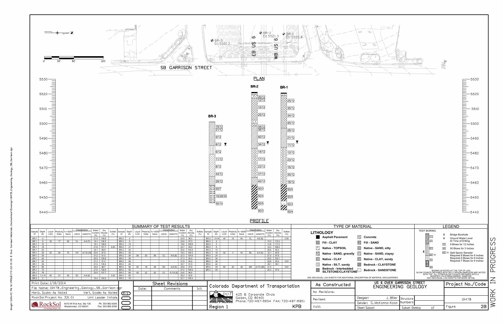
In August and September 2013, RockSol drilled 13 boreholes to evaluate the subsurface conditions for the US 6 over Garrison Bridge Replacement project. The borehole locations are identified as BR-1 through BR-6, RW-1 through RW-5 and PV-1 through PV-2, as shown on Figure 2, Borehole Location Plan and Figures 2A through 2D, Engineering Geology Sheets. Boreholes BR-1 through BR-6 were drilled at the approximate location of the proposed bridge structure, Boreholes RW-1 through RW-5 were drilled to assist with retaining wall foundation recommendations, and Boreholes PV-1 and PV-2 were drilled to assist with pavement thickness recommendations. The boreholes were located by field survey provided by the project surveyor (HKS). Horizontal and vertical locations were then provided to RockSol for inclusion on the Borehole Location Plan and on the borehole logs.
Truck mounted CME-45 and CME-55 drill rigs were used for drilling and sampling. The boreholes were advanced using 4-inch outside diameter solid stem augers and 8 inch outside diameter hollow stem augers to maximum depths ranging from approximately 10 feet to 80 feet below existing grades. The boreholes were logged in the field by a representative of RockSol with the depth to groundwater noted at the time of drilling. A monitoring well was drilled and installed near Borehole BR-4 for the project environmental team (Pinyon Environmental). Except for the monitoring well, the boreholes were backfilled at the completion of drilling and groundwater level checks. Boreholes drilled within existing pavement were patched with concrete and asphalt patch mixes.
Subsurface materials were sampled and resistance of the soil to penetration of the sampler was performed using modified California barrel and standard split spoon samplers. The modified California barrel sampler has an outside diameter of approximately 2.5 inches and an inside diameter of 2 inches. The standard split spoon sampler used had an outside diameter of 2 inches and an inside diameter of 1⅜-inches. Brass tube liners were used with the modified California barrel sampler. Brass tube liners are not used with the standard split spoon sampler.
Preliminary Geotechnical Investigation – Retaining Wall Structures US 6 Bridge over Garrison Street
Lakewood, Colorado
RockSol Project No. 329.02 4 July 3, 2014
Penetration Tests were performed at selected intervals using both a standard rope-cathead lift system and an automatic lift system. Both hammer lift systems used a hammer weighing 140 pounds and falling 30 inches. The standard split spoon sampling method is the Standard Penetration Test (SPT) described by ASTM Method D-1586. Penetration Tests were performed using the modified California barrel sampler with a standard hammer weighing 140 pounds falling 30 inches per ASTM D3550. The modified California Barrel sampling method is similar to the SPT test with the difference being the sampler dimensions and the number of 6-inch intervals driven with the hammer. Correlation of blow counts obtained from a modified California sampler to blow counts obtained from a standard split spoon sampler is not available. However, it is RockSol’s experience that blow counts obtained with the modified California sampler tend to be slightly greater than a standard split spoon sampler. Penetration resistance values (blow counts) were recorded for each sampling event. Blow counts, when properly evaluated, indicate the relative density or consistency of the soils.
Depths at which the samples were taken, the type of sampler used, and the blow counts that were obtained are shown on the Boring Logs for each borehole. Individual Borehole Logs are included in Appendix A. Engineering Geology Sheets for the project are included in Figures 2A through 2D.
4.0 LABORATORY TESTING
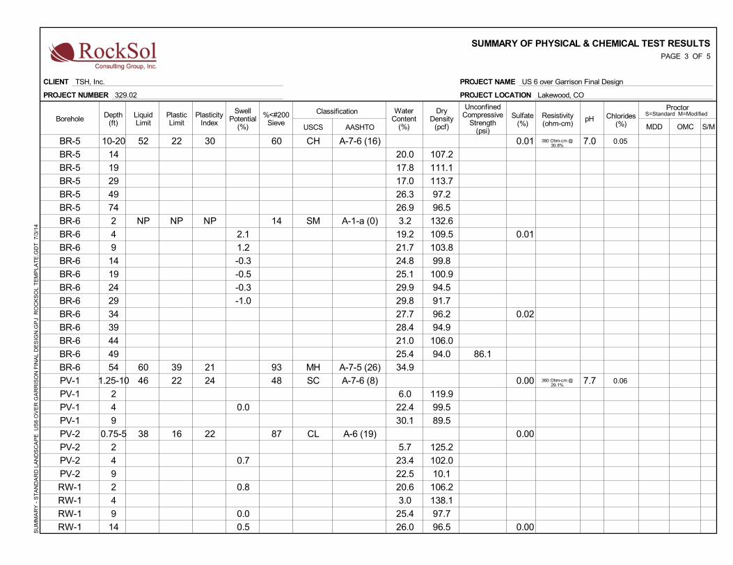
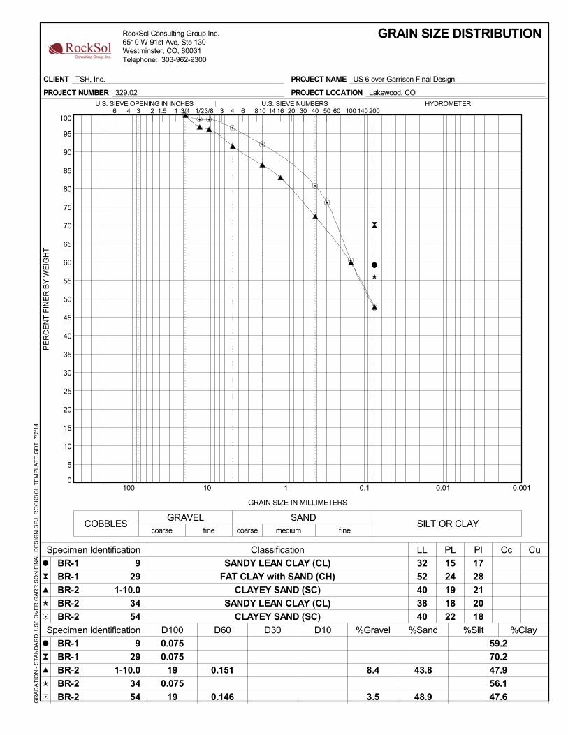
Soil samples retrieved from the borehole locations were examined by the project geotechnical engineer in the RockSol laboratory. Selected samples were tested and classified according to the Unified Soil Classification System (USCS). The following laboratory tests were performed in accordance with the American Society for Testing and Materials (ASTM), American Association of State Highway and Transportation Officials (AASHTO), and current local practices:
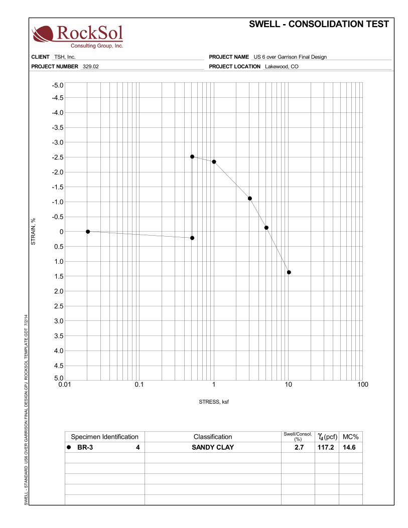
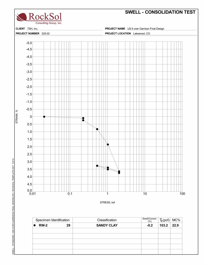
• Natural Moisture Content (ASTM D-2216) • Percent Passing No. 200 Sieve (ASTM D-1140) • Liquid and Plastic Limits (ASTM D-4318) • Dry Density (ASTM D-2937) • Gradation (ASTM C-117 and C-136) • Water Soluble Sulfate Content (CDOT CP-L 2103) • Soil Classification (ASTM D-2487, ASTM D-2488, and AASHTO M145) • Swell Test (ASTM D-4546) • Water Soluble Chloride Content (AASHTO T291-91) • Standard Test Method for pH of Soils (ASTM D4972-01) • Soil Resistivity (ASTM G187 - Soil Box) • Unconfined Compressive Strength Test (ASTM D2166)
Laboratory test results were used to characterize the engineering properties of the subsurface material. For soil classification, RockSol conducted sieve analyses and Atterberg Limits tests.Swell tests were used to determine the swell or consolidation characteristics of the subsurface materials. Lab testing was also performed on selected samples to determine the water soluble sulfate content of subsurface materials to assist with cement type recommendations. Laboratory test results are presented in Appendix B and are also summarized on the Borehole Logs presented in Appendix A.
Preliminary Geotechnical Investigation – Retaining Wall Structures US 6 Bridge over Garrison Street
Lakewood, Colorado
RockSol Project No. 329.02 5 July 3, 2014
5.0 SUBGRADE CHARACTERIZATION
Subsurface conditions generally consist of silty to clayey sand and sandy clay fill material within the US 6 approach embankments at Garrison Street and native soils consisting of silty to clayey sand and sandy clay overlying sedimentary bedrock. The sedimentary bedrock consisted of claystone with sandstone layers in parts. Groundwater was encountered at depths ranging from 14 feet to 37 feet below existing grades during drilling operations. Descriptions of the surface and subsurface conditions encountered in the boreholes are provided below and are also summarized on the Borehole Logs presented in Appendix A.
Roadway Pavement
Flexible pavement (asphalt) was encountered at the ground surface at eight borehole locations. Where flexible roadway pavement was encountered on US 6, the thickness generally ranged from 6.0 inches to 9.5 inches. At Boreholes BR-1, BR-2, BR-5, PV-1, and RW-2 approximately 4.0 inches to 8.5 inches of flexible asphalt pavement was noted overlying 7.5 inches to 10.5 inches of rigid pavement. Aggregate base course material was not noted below the pavement sections. The pavement core recovered at Borehole BR-5 included a layer of asphalt pavement, 8¼ inches in thickness, over 8½ inches rigid pavement, which was over a layer of asphalt pavement approximately 3¼ inches in thickness.
Topsoil
Topsoil was encountered at the ground surface at four borehole locations. The topsoil encountered was lightly organic sandy silt which supported a sparse covering of grasses and weeds. A topsoil thickness of approximately 3 inches to 6 inches was estimated based on field observations.
Fill Material
Beneath the pavement and topsoil, subsurface conditions encountered generally consisted of fill material to approximate depths ranging from 3 feet to 24 feet below existing grades and appears to be associated with the roadway embankment for US 6 over Garrison and the entrance and exit ramps for US 6. Fill material was not noted in Borehole BR-3. The fill material encountered generally consisted of medium stiff to very stiff sandy clay with gravel in parts. In Boreholes BR-2, BR-6, PV-1, and PV-2, fill material consisting of silty to clayey sand with gravel was encountered. A 2-foot layer of concrete debris was encountered at borehole location BR-2 at an approximate elevation of 5,502 feet, near the bottom of the embankment fill material.
Based on laboratory test results, the fill material encountered predominantly classified as A-6 soils by the American Association of State Highway and Transportation Officials (AASHTO) soil classification system. A-7-6 soils were also encountered. A summary of laboratory test results with soil classifications is presented in Appendix B.
Native Soils
Native soils encountered below the fill material or ground surface consisted of loose to dense silty to clayey sand with gravel in parts and stiff to hard sandy clay extending to elevations ranging from 5,455 feet to 5,460 feet where sedimentary bedrock was encountered.
Bedrock
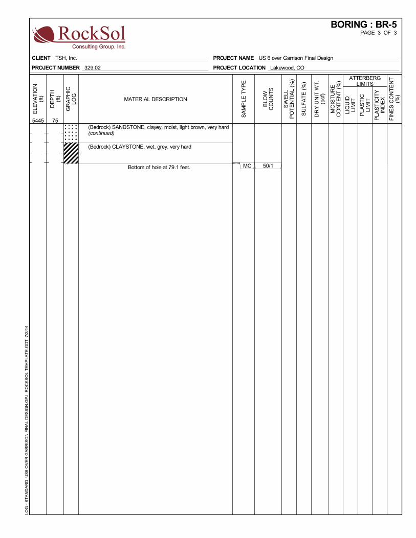
Sedimentary bedrock was encountered beneath the native soils in Boreholes BR-1 through BR-6 and RW-5 at elevations ranging from 5,455 feet to 5,461 feet during drilling operations. The bedrock generally consisted of very hard claystone. Very hard clayey sandstone and siltstone
Preliminary Geotechnical Investigation – Retaining Wall Structures US 6 Bridge over Garrison Street
Lakewood, Colorado
RockSol Project No. 329.02 6 July 3, 2014
bedrock layers were also noted in Boreholes BR-1 through BR-6. Bedrock was not noted to the maximum depths drilled (approximately 10 feet to 50 feet) at Boreholes PV-1, PV-2 and RW-1 through RW-4.
Groundwater
Groundwater was encountered in 11 boreholes at elevations ranging from 5,479 feet to 5,493 feet (approximate depths ranging from 14 feet to 37 feet below existing grades) during drilling operations. Groundwater was not encountered to the maximum depths drilled (approximately 10 feet below existing grades) at Boreholes PV-1 and PV-2.
A summary of the bedrock and groundwater elevations encountered is presented in Table 1. The approximate groundwater and bedrock elevations are rounded to the nearest one-half foot and are based on the depth to groundwater and bedrock noted during drilling and sampling operations and the ground surface elevations provided by the project surveyor.
Based on the groundwater elevations presented in Table 1, there appears to be a decreasing gradient predominately to the east. Based on the bedrock elevations presented in Table 1, the bedrock surface elevation appears to be decreasing in the northeast direction.
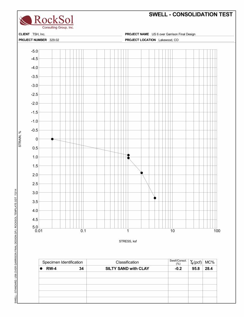
Expansive Soil Discussion Swell potential in the subgrade soils obtained within the upper 5 feet below existing and proposed pavement grades ranged from 0.0 percent (swell) to 1.8 percent (swell), when tested with a 200 pound per square foot (psf) surcharge, with the average swell less than 1 percent.
Swell potential in the subgrade soils obtained at a depth greater than 5 feet below existing and proposed grades ranged from -1.0 percent (consolidation) to 1.4 percent (swell), when tested with a 200-psf to 1,000-psf surcharge.
Based on the swell test data, the subgrade soils appear to possess a low swell potential and low consolidation potential. Based on our understanding of the proposed improvements for this project, it is RockSol’s opinion that special earthwork requirements for swell mitigation is not deemed necessary for this project.
Sulfate Resistance Discussion Cementitious material requirements for concrete in contact with site soils or groundwater are based on the percentage of water soluble sulfate in either soil or groundwater that will be in
Preliminary Geotechnical Investigation – Retaining Wall Structures US 6 Bridge over Garrison Street
Lakewood, Colorado
RockSol Project No. 329.02 7 July 3, 2014
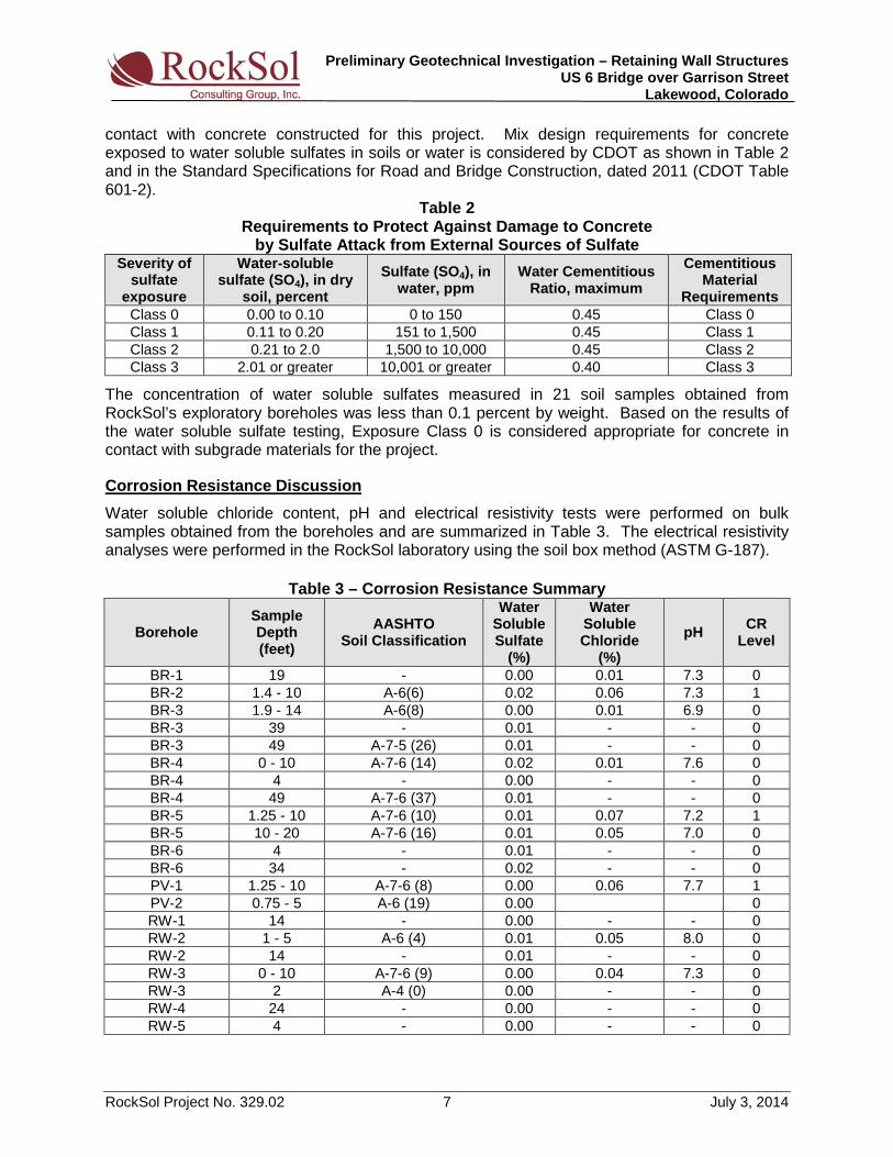
contact with concrete constructed for this project. Mix design requirements for concrete exposed to water soluble sulfates in soils or water is considered by CDOT as shown in Table 2 and in the Standard Specifications for Road and Bridge Construction, dated 2011 (CDOT Table 601-2).
Table 2 Requirements to Protect Against Damage to Concrete
by Sulfate Attack from External Sources of Sulfate Severity of
sulfate exposure
Water-soluble sulfate (SO4), in dry
soil, percent Sulfate (SO4), in
water, ppm Water Cementitious
Ratio, maximum Cementitious
Material Requirements
Class 0 0.00 to 0.10 0 to 150 0.45 Class 0 Class 1 0.11 to 0.20 151 to 1,500 0.45 Class 1 Class 2 0.21 to 2.0 1,500 to 10,000 0.45 Class 2 Class 3 2.01 or greater 10,001 or greater 0.40 Class 3
The concentration of water soluble sulfates measured in 21 soil samples obtained from RockSol’s exploratory boreholes was less than 0.1 percent by weight. Based on the results of the water soluble sulfate testing, Exposure Class 0 is considered appropriate for concrete in contact with subgrade materials for the project.
Corrosion Resistance Discussion Water soluble chloride content, pH and electrical resistivity tests were performed on bulk samples obtained from the boreholes and are summarized in Table 3. The electrical resistivity analyses were performed in the RockSol laboratory using the soil box method (ASTM G-187).
Preliminary Geotechnical Investigation – Retaining Wall Structures US 6 Bridge over Garrison Street
Lakewood, Colorado
RockSol Project No. 329.02 8 July 3, 2014
Of the three variables (water soluble sulfate, water soluble chloride, and pH) that are used in determining the CR level, the water soluble chloride content appears to be the predominant component affecting the CR level selection. The water soluble sulfate and pH components do not appear to contribute to an elevated CR level selection. The CDOT CR levels attributed to tests performed on samples obtained from each borehole are presented in Table 3 of this report. CDOT CR levels range from CR0 to CR6 with CR0 being the lowest level. The current CDOT Pipe Materials Selection Policy can be accessed at the following link: http://www.coloradodot.info/business/designsupport/design-docs/cdot_pipe_selection_policy/view.
In addition, seven electrical resistivity analyses were performed in the RockSol laboratory using the soil box method (ASTM G-187). Electrical resistivity testing was performed on bulk samples obtained within the upper 10 feet at borehole locations BR-2, BR-4, BR-5, PV-1, RW-2, RW-3 and was performed on bulk samples obtained within the upper 10 feet to 20 feet at Borehole BR-5. Based on the laboratory electrical resistivity test results (all seven less than 1,000 Ohm-cm), an aggressive corrosion condition for steel pipe and reinforcement bars is indicated for the project site based on criteria presented in Table 3.9 of FHWA report FHWA0-IF-3-017, Geotechnical Engineering Circular No.7 – Soil Nail Walls. The Geotechnical Engineering Circular No.7 – Soil Nail Walls document can be accessed at the following link:
http://isddc.dot.gov/OLPFiles/FHWA/016917.pdf.
6.0 GEOLOGICAL SETTING The project site is located between two gulches, Lakewwod Gulch and McIntyre Gulch, and approximately 3 miles south of the southern limits of the geologic floodplain of Clear Creek. Based on the 1979 USGS Geologic Map of the Greater Denver Area, Front Range Urban Corridor by Donald E. Trimble and Michael N. Machette (see Image 1 – Site Geology Map below, modified by RockSol), the site is underlain by Verdos Alluvium (Qvl) generally consisting of boulder cobble gravel and artificial fill material (af) associated with the bridge approach embankments. Post-Piney and Piney Creek Alluvium (Qp), Loess (Ql) and Broadway Alluvium (Qb) soil deposits are mapped to the south and north of the US 6 and Garrison interchange and generally consist of sands, gravels, silts, clays, and minor amounts of cobbles and boulders deposited by existing and historic stream flows.
Preliminary Geotechnical Investigation – Retaining Wall Structures US 6 Bridge over Garrison Street
Lakewood, Colorado
RockSol Project No. 329.02 9 July 3, 2014
Bedrock units are not mapped within the interchange area but the Denver Formation (Tkda) is mapped at or near the surface approximately ½ mile to the east. Based on information presented in the USGS geologic map and information obtained in the RockSol boreholes drilled for this investigation, the sedimentary bedrock encountered in the boreholes appear to be consistant with the Denver Formation. The Denver Formation generally consists of claystone, sandstone, siltstone, and conglomerate.
7.0 PRELIMINARY RETAINING WALL RECOMMENDATIONS New retaining wall structures associated with the bridge replacement are proposed along US6 at the northwest, northeast, southwest and southeast quadrants of the Garrison Street interchange. Retaining walls will be required to retain fill material at the US 6 bridge over Garrison Street approach embankment locations. Based on our understanding and discussions with the retaining wall design team, a cast-in-place (CIP) reinforced concrete cantilever retaining wall system is being considered for the four proposed wall locations, which will incorporate a shallow footing foundation system. Maximum retaining wall heights are anticipated between 10 to 19 feet for single retaining wall systems. Descriptions of the proposed retaining wall systems for this project are presented in Table 4. Estimated retaining wall heights, location and bottom of wall footing elevations are based on the untitled drawing provided by CH2M HILL on December 31, 2013, included in Appendix C of this report.
Table 4 – Proposed Retaining Wall Summary Wall
Identification/ Apprx. Station No.
Approximate Wall Length (ft)
Approximate Wall Height (ft)
Approximate Bottom Wall Elevation (ft)
Corresponding RockSol Boreholes
NW Quadrant – 102+35 to 110+15 780 2 to 19 5,500 to 5,516 BR-1, PV-1, RW-1 and RW-2
NE Quadrant – 112+00 to 116+16 416 10 to 19 5,498 to 5,499 BR-4 and BR-5 (Note 1)
SW Quadrant – 108+56 to 110+03 150 18 5,501 BR-2, BR-3 and RW-3 (Note 1)
SE Quadrant – 111+81 to 120+35 855 3 to 18 5,493 to 5,501 BR-5, BR-6, RW-4, RW-5 and
PV-2 Note 1: Wall locations NE and SW were added subsequent to RockSol’s field exploration. Additional boreholes are recommended for final design.
Design of the retaining walls is by the Load and Resistance Factor Design (LRFD) method. Based on conditions encountered in our borings and on our geotechnical evaluation, preliminary LRFD nominal and factored bearing resistances presented in Table 5 are recommended for the Retaining Walls NW, NE, SW, and SE footing foundation systems. A resistance factor of 0.45 is used to determine the factored bearing resistance for LRFD strength limit state evaluation.
Table 5 – Preliminary Bearing Resistances Recommend for Footing Foundations
Structure Location
Strength Limit State (LRFD) Service Limit State (LRFD)
Nominal Resistance
(ksf)
Factored Resistance
(ksf) Service Bearing Resistance (LRFD)
(ksf)
NW Quadrant – 102+35 to 110+15 10.6 4.8 3.0 NE Quadrant – 112+00 to 116+16 10.6 4.8 3.0 SW Quadrant – 108+56 to 110+03 8.1 3.6 2.5 SE Quadrant – 111+81 to 120+35 10.6 4.8 3.0
Preliminary Geotechnical Investigation – Retaining Wall Structures US 6 Bridge over Garrison Street
Lakewood, Colorado
RockSol Project No. 329.02 10 July 3, 2014
Drainage of retained soil behind all walls is recommended. Surface water infiltration of wall backfill zones may occur. Positive internal and external surface drainage to eliminate hydrostatic pressure is recommended. A minimum embedment of 3 feet is recommended for shallow footing foundation systems.
The design and construction criteria presented below should be observed for CIP reinforced concrete cantilever retaining wall footings. These construction details should be considered when preparing project documents.
1. Retaining wall footings shall be placed on undisturbed existing soils/bedrock and/or properly compacted structural fill.
2. The retaining wall footings should be provided with adequate soil cover above their
bearing elevation for frost protection. Placement of foundations at least 36 inches below the exterior grade is recommended.
3. The lateral resistance of retaining wall footings can be achieved through combination
of the sliding resistance of the footing on the foundation materials and passive earth pressure against the side of the footing or lateral resistance key. Footings should be cast neatly against undisturbed soil.
4. Care should be taken when excavating the retaining wall foundations to avoid
disturbing the supporting materials. 5. A representative of the geotechnical engineer should observe all footing excavations
prior to concrete placement.
Cantilevered retaining structures can be expected to deflect sufficiently to mobilize the full active earth pressure condition. Estimated ultimate (unfactored) earth pressure coefficients for vertical wall facing, a wall/backfill interface friction angle of zero degrees and using imported CDOT Class 1 Structure Backfill material or CDOT Class 6 Aggregate Base Course material are presented in Table 6A.
Note 1: For horizontal backslope. Note 2: For 4 (H): 1(V) backslope.
Test results should be provided by the contractor prior to construction for the proposed wall backfill material indicating compliance with CDOT specifications for Class 1 or Class 6 gradation
Preliminary Geotechnical Investigation – Retaining Wall Structures US 6 Bridge over Garrison Street
Lakewood, Colorado
RockSol Project No. 329.02 11 July 3, 2014
and the effective friction angle indicated in Table 6A. The equivalent fluid pressures recommended above does not include hydrostatic pressure from water build-up behind the wall which must be superimposed to calculate loads unless a “behind the wall” drainage system is be included in the retaining wall. The lateral earth pressures in Table 6A do not include surcharge loadings such as traffic, construction equipment or fill stockpiles at or near the top of walls.
Compacted fill placed behind the retaining wall should be a granular material such as CDOT Class 1 structure backfill or CDOT Class 6 aggregate base course. Wall backfill should be compacted with light weight, hand operated equipment. The lateral earth pressure values provided in this report assume light weight hand operated compaction equipment will be used to compact backfill within 5 feet of the inside wall face.
For the evaluation of sliding, we anticipate that wall foundations will be constructed on existing clay soils. Per AAHSTO LRFD Section 10.6.3.4, for footings that rest on clay subgrade, the sliding resistance may be taken as the lesser of: 1) The cohesion of the clay, or; 2) Where footings are supported on at least 6.0 inches of compacted granular material, one-half the normal stress on the interface between the footing and soil. If passive resistance is included as part of the shear resistance required for resisting sliding, passive pressures may be estimated by AASHTO LRFD Equation 3.11.5.4-1. Consideration should be given to possible future removal of the soil in front of the wall foundation.
An estimated ultimate (unfactored) passive earth pressure coefficient for material in front of the wall foundation toe is presented in Table 6B. If passive resistance is included, a resistance factor of 0.5 for passive resistance is recommended, per AASHTO LRFD Table 10.5.5.2.2-1.
Passive Lateral Earth Pressure Coefficient (kp) Total
Unit Weight (γ) pcf
Effective Friction Angle
(φ′)
Undrained Shear
Strength Su (ksf) (Note 3)
Horizontal Foreslope (Note 1)
4 (H): 1 (V Foreslope (Note 2)
with shear key
w/o shear key
NW, NE, SW, and western portion of SE
Clay 2.20 1.46 120 28 1.4 1.4
Eastern portion of SE Sand 3.26 2.07 125 32 - -
Note 1: Based on horizontal slope at the bottom of the wall. Note 2: Based on a 4 horizontal to 1 vertical descending slope away from the bottom of the wall. Note 3: With shear key, soil on soil sliding resistance in front of shear key. Without shear key, soil on concrete sliding resistance.
8.0 SEISMICITY DISCUSSION
RockSol boreholes terminated at depths less than 100 feet below the ground surface and shear wave velocity testing was not performed. Based on the subsurface conditions encountered and using the Method B procedure of AASHTO Table C3.10.3.1-1, it is RockSol’s opinion that AASHTO Seismic Site Class D is appropriate for design of the US6 Bridge over Garrison Street structure. Soil conditions necessary for Site Class E and F were not encountered by RockSol. Shear wave
Preliminary Geotechnical Investigation – Retaining Wall Structures US 6 Bridge over Garrison Street
Lakewood, Colorado
RockSol Project No. 329.02 12 July 3, 2014
velocity testing would be necessary to determine if Site Class C conditions, or higher, are present. Seismic design parameters for Seismic Site Class D are discussed below.
Seismic design parameters were obtained from the 2007 United States Geological Survey (USGS) Seismic Design Parameters CD (Version 2.10) using the AASHTO Earthquake Motion Parameters Program. The values provided are for a 7 percent probability of exceedance in 75 years. Interpolated values for Peak Ground Acceleration Coefficient (PGA), Spectral Acceleration Coefficient at Period 0.2 sec (Ss), and Spectral Acceleration Coefficient at Period 1.0 sec (S1) were obtained using the latitude and longitude for the bridge structure.
The seismic acceleration coefficients obtained (data based on 0.05 degree grid spacing) are presented in Table 7.
Table 7 – Seismic Acceleration Coefficients
Location (Latitude°/Longitude°)
Peak Ground Acceleration
(PGA)
Spectral Acceleration
Coefficient - Ss (Period 0.2 sec)
Spectral Acceleration
Coefficient - S1 (Period 1.0 sec)
US6 Bridge over Garrison Street (39.725486°/-105.100224°) 0.061 0.130 0.034
The acceleration coefficients are then used to obtain Site Factors Fpga, Fa, and Fv based on the defined Site Class as shown in Tables 3.10.3.2-1, 3.10.3.2-2, and 3.10.3.2-3 of the AASHTO LRFD. A summary of the Site Factor values are shown in Table 8.
Table 8 – Seismic Site Factor Values
Bridge Location Fpga (at zero-period on acceleration spectrum)
Fa (for short period range of acceleration spectrum)
Fv (for long period range of acceleration spectrum)
US6 Bridge over Garrison Street 1.60 1.60 2.40
Seismic Performance Zone determination is based on the value of the Acceleration Coefficient, SD1, as determined by Eq. 3.10.4.2-6 of the AASHTO LRFD (SD1 = Fv×S1).
Table 9 outlines the Seismic Zone determination and Acceleration Coefficient obtained for the proposed US 6 bridge structure over Garrison Street.
Table 9 – Seismic Performance Zone
Bridge Location Acceleration Coefficient (SD1)
Seismic Zone (1)
US6 Bridge over Garrison Street 0.083 1
Note (1): Seismic Zone 1 is assigned when SD1 ≤ 0.15.
9.0 EMBANKMENT AND SITE GRADING
Where fill material is to be placed on existing slopes steeper than 4 (H):1 (V), benching must be performed to tie the new fill into the existing slope per 2011 CDOT Standard Specifications for Road and Bridge Construction (CSSRBC), Section 203. Benching into the existing slopes shall allow sufficient bench width to accommodate placing and compaction equipment to operate in a horizontal orientation.
Preliminary Geotechnical Investigation – Retaining Wall Structures US 6 Bridge over Garrison Street
Lakewood, Colorado
RockSol Project No. 329.02 13 July 3, 2014
9.1 Material Specifications
The following material specifications are presented for earthwork on the project.
1. Soil Embankment: As stated in the 2011 CSSRBC, Section 203.03, material shall be soil predominately of materials smaller than No. 4 sieve in diameter, with a maximum particle size of less than 6 inches in diameter recommended. Soil embankment shall be constructed with moisture and density control. It is anticipated that material excavated from the proposed cut slopes may be reused as embankment material; however, additional testing will need to be performed to confirm Project specifications.
2. Retaining Wall Backfill: Shall consist of granular material meeting CDOT Structure Backfill (Class 1) requirements presented in the 2011 CSSRBC Section 703.08 or CDOT Class 6 Aggregate Base Course presented in Section 703.03 of the 2011 CSSRBC.
3. Unsuitable Material: Vegetation, brush, sod, trash, and other deleterious substances
shall not be placed in embankment, excavation backfill, or structural backfill.
9.2 Compaction Specifications Compaction of fill materials should be achieved near optimum moisture content. A representative of the geotechnical engineer should observe and test fill placement operations. The minimum compaction recommended for specific applications is presented in Table 10.
Table 10 –Compaction Specifications AASHTO
Classification Minimum Relative Compaction
(Percentage of MDD), % Moisture Content
(Deviation from OMC) A-1, A-2-4, A-2-5,
A-3, 95% of AASHTO T180 -2 to +2
A-2-6, A-2-7, A-4, A-5, A-6 and A-7 95% of AASHTO T99 -2 to +2
9.3 Subgrade Preparation Prior to construction of foundations and embankments the underlying subgrade should be properly prepared by removal of all organic matter (topsoil), debris, loose material, and any deleterious material identified by the Project Engineer followed by scarification, moisture conditioning and recompaction. Unless otherwise specified, the minimum depth of scarification, moisture conditioning and re-compaction in all cases shall be 6 inches and compacting to a minimum of 95 percent of maximum dry density (MDD) as determined by AASHTO T99 (standard proctor) and moisture conditioned to within 2 percent of Optimum Moisture Content (OMC). Cobbles greater than 6 inches in diameter, if encountered, should be removed from the scarification zone.
10.0 OTHER DESIGN AND CONSTRUCTION CONSIDERATIONS Proper construction practices, in accordance with CDOT Standard Specifications for Road and Bridge Construction, should be followed during site preparation, earthwork, excavations, and embankment and retaining wall construction for the suitable long term performance of the proposed improvements. Excavation support should be provided to maintain onsite safety and
Preliminary Geotechnical Investigation – Retaining Wall Structures US 6 Bridge over Garrison Street
Lakewood, Colorado
RockSol Project No. 329.02 14 July 3, 2014
the stability of excavations and slopes. Excavations shall be constructed in accordance with local, state and federal regulations including OSHA guidelines. The contractor must provide a competent person to determine compliance with OSHA excavation requirements. For preliminary planning, existing fill material and native soils may be considered as OSHA Type C soils.
The actual subsurface conditions between boring locations may vary from the information obtained at specific boring locations and described in this report.
Surface drainage patterns may be altered during construction and surface drainage must be controlled to prevent excessive moisture infiltration into the subgrade soils at all retaining wall locations during and after construction. Concrete paved surface drainage swales are recommended at the top of all retaining walls and slopes to catch and transport surface drainage away from the walls and slopes.
Environmentally contaminated material, if encountered, should be characterized and removed under the direction of the project environmental consultant. Design and construction plans should be reviewed and onsite construction should be observed by the professional engineers.
11.0 LIMITATIONS This geotechnical field investigation was conducted in general accordance with the scope of work. The geotechnical practices are similar to that used in the Colorado Front Range area with similar soil conditions and our understanding of the proposed work. This report has been prepared by RockSol for use by the Colorado Department of Transportation exclusively for the project described in this report. The report is based on our exploratory boreholes and does not take into account variations in the subsurface conditions that may exist between boreholes. Additional investigation is required to address such variation. If during construction activities, materials or water conditions appear to be different from those described herein, RockSol should be advised at once so that a re-evaluation of the recommendations presented in this report can be made. RockSol is not responsible for liability associated with interpretation of subsurface data by others.
mckanna-koon 11:1
8:3
7
AM
M:\
PR
OJE
CT
S\
321.0
1 U
S 6
Over
Garris
on\
Materials
_Geotechnic
al\
Dra
win
gs\
194
78_
Site_
Vicinity.d
gn
Sheet Subset:
Detailer:
Designer:
Project No./Code1/6/2014Print Date:
Horiz. Scale:
19478_Site_Vicinity.dgnFile Name:
Westminster, CO 80031
6510 W 91st Ave, Ste 130
0
Figure
J. Biller
19478
S. McKanna-Koon
AS NOTED
SITE VICINITY MAP
US 6 OVER GARRISON STREET
IMAGE COURTESY OF THE U.S. GEOLOGICAL SURVEY, JUNE 2009, FORT LOGAN, COLORADO QUADRANGLE, 2011
Location
Site
Approximate
1000 2000 3000
(FEET, APPROXIMATE SCALE) 1
100'0' 50' 200'
R. LEPRO
S. MCKANNA-KOON
2
BOREHOLE LOCATION PLAN
WB US6
EB US6
NB
GA
RRIS
ON
ST
SB
GA
RRIS
ON
ST
106
+00
107
+00
108
+00
109
+00
111+00
112
+00
113
+00
114
+00
116
+00
117
+00
118
+00
119
+00
104
+3
0
PP
5RB GPC CP
N 690187.84
E 113217.24
EL 5493.45
PP
5RB GPC CP
N 689768.80
E 114079.30
EL 5494.55
PP
PP
5RB GPC CP
N 689890.96
E 114027.72
EL 5496.14
N 689890.99
E 114027.71
EL 5496.24
5RB GPC CP
N 689925.87
E 113286.28
EL 5498.03
PP
CHIS X
N 689723.70
E 113687.69
EL 5499.39
PP
CHIS X
N 689665.06
E 113201.91
EL 5502.24
TOTAL STATION OBS
MAG NAIL & WASHER
N 689915.67
E 113000.90
EL 5502.67
PP
BM
PP
3.5"AC CDOT CNT MON. ML PST 4.005093
N 689687.42
E 112840.22
EL 5507.37
5RB GPC CP
N 689877.56
E 112574.19
EL 5511.10
105
+00
110
+00
115
+00
Numbers
Structure
No Revisions:
Revised:
Void:
Detailer:
Designer:
Subset Sheets:
Init.CommentsDate:
Sheet Revisions As Constructed12/16/2013Print Date:
File Name:
Vert. Scale:
of
Horiz. Scale:
19478_BoreholeLocationPlan.dgn
Project No./Code
R-X
Unit Leader
mckanna-koon 2:4
7:5
8
PM
M:\
PR
OJE
CT
S\
321.0
1 U
S 6
Over
Garris
on\
Materials
_Geotechnic
al\
Dra
win
gs\
194
78_
Borehole
Locatio
nPla
n.d
gn
Phone:720-497-6954 FAX:720-497-6951
Colorado Department of Transportation
Region 1
425 B Corporate Circle
Golden, CO 80401
KPB Sheet Subset:
19478
WO
RK IN
PR
OG
RE
SS
Fax: 303-962-9350
Ph: 303-962-9300
Westminster, CO 80031
6510 W 91st Ave, Ste 130
As Noted As Noted
Figure
RockSol Project No. 321.01
US 6 OVER GARRISON STREET
El: 5497.8
BR-4
El: 5504.8
RW-3
El: 5501.2
BR-3
El: 5501.1
BR-6
El: 5498.1
PV-2
El: 5499.5
RW-5
El: 5521.3
BR-2El: 5520.4
BR-5
El: 5516.4
RW-4
El: 5514.0
RW-1El: 5518.9
RW-2
El: 5513.3
PV-1 El: 5520.8
BR-1
5505
5505
5510
55105510
5510
5515
55155515
5515
5515
5520
E 112574.19
EL 5511.10
Numbers
Structure
No Revisions:
Revised:
Void: Sheet Subset:
Detailer:
Designer:
Subset Sheets:
Init.CommentsDate:
R-X
Sheet Revisions As Constructed11/13/2013Print Date:
Horiz. Scale:
19478_Engineering_Geology_West_US6.dgn
Vert. Scale: As Noted
Unit Leader Initials
File Name:
mckanna-koon 4:4
7:2
9
PM
M:\
PR
OJE
CT
S\
321.0
1 U
S 6
Over
Garris
on\
Materials
_Geotechnic
al\
Dra
win
gs\
194
78_
Engin
eerin
g_
Geolo
gy_
West_
US6.d
gn
Project No./Code
Fax: 303-962-9350
Ph: 303-962-9300
Westminster, CO 80031
6510 W 91st Ave, Ste 130
of
TYPE OF MATERIAL LEGENDSUMMARY OF TEST RESULTS
SEE INDIVIDUAL LOG SHEETS FOR ADDITIONAL DESCRIPTION OF MATERIAL ENCOUNTERED
(ft)
Depth
Limit
Liquid
Index
Plasticity
Sieve
%< #200
AASHTO(%)
Content
Water
(%)
Density
Dry
(%)
Sulfate
ID
Sample
USCS
Classification
(ft)
Depth
Limit
Liquid
Index
Plasticity
Sieve
%< #200
AASHTO(%)
Content
Water
(%)
Density
Dry
(%)
Sulfate
ID
Sample
USCS
Classification
(ft)
Depth
Limit
Liquid
Index
Plasticity
Sieve
%< #200
AASHTO(%)
Content
Water
(%)
Density
Dry
(%)
Sulfate
ID
Sample
USCS
Classification TEST BORING
9 Blows for 12 Inches
50 Blows for 3 Inches
11/12
6/12
28/12
8/6/7
50/6
50/8
At Time of Drilling
Ground Water Level
50/3
9/12
8/6/7
Bridge Borehole
Required 7 Blows for 6 Inches
Required 6 Blows for 6 Inches
Required 8 Blows for 6 Inches
Split Spoon Sampler
SEE INDIVIDUAL LOG SHEETS FOR MORE DETAILMODIFIED CALIFORNIA BARREL SAMPLER
WITH "SS". ALL OTHER BLOW COUNTS OBTAINED WITH A BLOW COUNTS OBTAINED WITH SPLIT SPOON SAMPLERS ARE NOTED
BORING ID NOTED AT THE TOP OF LOG
SS
SS
B
PROFILE
PLAN
WO
RK IN
PR
OG
RE
SS
19478Phone:720-497-6954 FAX:720-497-6951
Colorado Department of Transportation
Region 1
425 B Corporate Circle
Golden, CO 80401
KPB
J. Biller
S. McKanna-Koon
Figure
As Noted
RockSol Project No. 321.01
US 6 OVER GARRISON STREET
5500
5490
5480
5530
5520
62/12
26/12
19/12
PV-1PV-1PV-1PV-1PV-1PV-1
14/12
50/12
16/12
10/12
14/12
6/12
7/12
RW-1RW-1RW-1RW-1RW-1RW-1
RW-2RW-2RW-2RW-2RW-2RW-2
19/12
50/5
18/12
30/12
25/12
15/12
10/12
14/12
14/12
20/12
28/12
17/12
12/12
12/12
12/12
13/12
RW-3RW-3RW-3RW-3RW-3RW-3
5470
5510
5500
5490
5480
5530
5520
5470
5510
60'0' 30' 120'
LITHOLOGY
Asphalt Pavement Concrete
Fill - CLAY Fill - SAND
Native - TOPSOIL Native - SAND, silty
Native - SAND, gravelly Native - SAND, clayey
Native - CLAY Native - CLAY, sandy
Native - SILT, sandy Bedrock - CLAYSTONE
Bedrock - Interbedded
SILTSTONE/CLAYSTONEBedrock - SANDSTONE
105
+00
110
+00
110+00105+00
RW-1 14 26.0 96.5 0.00
RW-1 19 29.1 92.3
RW-1 24 37.4 85.1
RW-1 29 30.2 90.3
RW-2 1-5 38 18 44 SC A-6 (4) 0.01
RW-2 2 18.6 108.9
RW-2 4 17.3 110.7
RW-2 9 31 16 30 SC A-2-6 (1) 11.4 111.6
PV-1 1.25-10 46 24 48 SC A-7-6 (8) 0.00
PV-1 2 6.0 119.9
PV-1 4 22.4 99.5
PV-1 9 30.1 89.5
RW-1 2 20.6 106.2
RW-1 4 3.0 138.1
RW-1 9 25.4 97.7
19.7 108.8
RW-3 9 18.7 107.2
RW-3 14 40 17 38 SC A-6 (2) 25.9 97.7
RW-3 19 27.3 97.2
RW-3 24 30.7 96.0
RW-2 14 14.5 111.9
RW-2 19 47 27 76 CL A-7-6 (20) 20.4 105.4
RW-2 24 17.9 105.4
RW-2 29 22.9 103.2
RW-2 39 24.6 99.7
RW-3 0-10 43 23 54 CL A-7-6 (9)
RW-3 2 NP NP 47 SM A-4 (0) 10.1 117.8
RW-3 4
0.01
0.00
0.00
ENGINEERING GEOLOGY
2A
WB US 6
EB US 6
El: 5513.3
PV-1 El: 5514.0
RW-1El: 5518.9
RW-2
El: 5504.8
RW-3
5500
55005505
5510
5515
5520
5R
B
GP
C
CP
N 690187.8
4
E 113217.2
4
EL 54
93.4
5PP
PP
CHIS
X
N 689665.0
6
E 113201.9
1
EL 5502.2
4
BM
Numbers
Structure
No Revisions:
Revised:
Void: Sheet Subset:
Detailer:
Designer:
Subset Sheets:
Init.CommentsDate:
R-X
Sheet Revisions As Constructed1/16/2014Print Date:
Horiz. Scale:
19478_Engineering_Geology_SB_Garrison.dgn
Vert. Scale: As Noted
Unit Leader Initials
File Name:
dknig
ht 5:0
4:4
2
PM
M:\
PR
OJE
CT
S\
321.0
1 U
S 6
Over
Garris
on\
Materials
_Geotechnic
al\
Dra
win
gs\
194
78_
Engin
eerin
g_
Geolo
gy_
SB_
Garris
on.d
gn
Project No./Code
Fax: 303-962-9350
Ph: 303-962-9300
Westminster, CO 80031
6510 W 91st Ave, Ste 130
of
TYPE OF MATERIAL LEGENDSUMMARY OF TEST RESULTS
SEE INDIVIDUAL LOG SHEETS FOR ADDITIONAL DESCRIPTION OF MATERIAL ENCOUNTERED
(ft)
Depth
Limit
Liquid
Index
Plasticity
Sieve
%< #200
AASHTO(%)
Content
Water
(%)
Density
Dry
(%)
Sulfate
ID
Sample
USCS
Classification
(ft)
Depth
Limit
Liquid
Index
Plasticity
Sieve
%< #200
AASHTO(%)
Content
Water
(%)
Density
Dry
(%)
Sulfate
ID
Sample
USCS
Classification
(ft)
Depth
Limit
Liquid
Index
Plasticity
Sieve
%< #200
AASHTO(%)
Content
Water
(%)
Density
Dry
(%)
Sulfate
ID
Sample
USCS
Classification TEST BORING
9 Blows for 12 Inches
50 Blows for 3 Inches
11/12
6/12
28/12
8/6/7
50/6
50/8
At Time of Drilling
Ground Water Level
50/3
9/12
8/6/7
Bridge Borehole
Required 7 Blows for 6 Inches
Required 6 Blows for 6 Inches
Required 8 Blows for 6 Inches
Split Spoon Sampler
SEE INDIVIDUAL LOG SHEETS FOR MORE DETAILMODIFIED CALIFORNIA BARREL SAMPLER
WITH "SS". ALL OTHER BLOW COUNTS OBTAINED WITH A BLOW COUNTS OBTAINED WITH SPLIT SPOON SAMPLERS ARE NOTED
BORING ID NOTED AT THE TOP OF LOG
SS
SS
B
PROFILE
WO
RK IN
PR
OG
RE
SS
19478Phone:720-497-6954 FAX:720-497-6951
Colorado Department of Transportation
Region 1
425 B Corporate Circle
Golden, CO 80401
KPB
J. Biller
S. McKanna-Koon
Figure
As Noted
RockSol Project No. 321.01
US 6 OVER GARRISON STREET
5470
5460
5450
5500
5490
5440
5480
60'0' 30' 120'
ENGINEERING GEOLOGY
2B
El: 5520.8
BR-1El: 5521.3
BR-2
El: 5501.2
BR-3
PLAN5530
5520
5510
SB GARRISON STREET
WB
US 6
EB
US 6
5470
5460
5450
5500
5490
5440
5480
5530
5520
5510
LITHOLOGY
Asphalt Pavement Concrete
Fill - CLAY Fill - SAND
Native - TOPSOIL Native - SAND, silty
Native - SAND, gravelly Native - SAND, clayey
Native - CLAY Native - CLAY, sandy
Native - SILT, sandy Bedrock - CLAYSTONE
Bedrock - Interbedded
SILTSTONE/CLAYSTONEBedrock - SANDSTONE
BR-1BR-1BR-1BR-1BR-1BR-1BR-2BR-2BR-2BR-2BR-2BR-2
BR-3BR-3BR-3BR-3BR-3BR-3
BR-1 4 21.4 104.8
BR-1 9 32 17 59 CL A-6 (7) 18.1 108.5
BR-1 14 19.1 109.8
BR-1 19 21.8 101.7 0.00
BR-1 24 24.1 99.9
BR-1 29 52 28 70 CH A-7-6 (19) 25.9 97.6
BR-1 34 31.2 91.5
BR-1 44 25.5 100.8
BR-1 54 31.3 91.0
BR-1 59 21.5 109.5
BR-1 69 33.2 86.7
BR-1 74 21.0 102.9
BR-1 79 20.9 107.7
BR-2 1.4-10 40 21 48 SC A-6 (6) 0.02
BR-2 2 15.4 103.2
BR-2 4 24.9 98.2
BR-2 9 23.9 97.0
BR-2 14 19.6 109.9
BR-2 21 24.7 99.0
BR-2 24 20.6 104.8
BR-2 29 19.2 109.3
BR-2 34 38 20 56 CL A-6 (8) 22.3 104.9
BR-2 39 31.3 90.0
BR-2 44 31.8 90.6
BR-2 49 30.7 91.9
BR-2 54 40 18 48 SC A-6 (5) 25.8 97.8
BR-2 59 21.0 106.9
BR-2 64 46 22 52 CL A-7-6 (8) 24.6 96.6
BR-2 69 26.2 93.8
BR-2 79 22.7 100.4
BR-3 1.9-14 40 15 64 CL A-6 (8) 0.00
BR-3 2 15.3 110.3
BR-3 4 14.6 117.2
BR-3 9 16.4 108.4
BR-3 14 28.6 94.2
BR-3 19 32 3 54 ML A-4 (0) 33.1 90.9
BR-3 24 27.3 97.6
BR-3 34 25.5 102.1
BR-3 39 29.8 93.4 0.01
BR-3 44 28.1 98.1
BR-3 49 59 22 92 MH A-7-5 (26) 31.5 0.01
BR-3 54 25.3 97.0
25/12
30/12
34/12
40/12
28/12
21/12
11/12
12/12
23/12
16/12
35/12
18/12
50/5
50/5
50/3
50/4
20/12
12/12
15/12
25/12
34/12
36/12
40/12
34/12
14/12
17/12
22/12
37/12
40/12
50/3
50/4
50/5
50/3
15/12
21/12
9/12
8/12
6/12
11/12
8/12
44/12
28/12
50/7
18/28/30
50/10
5495
5500
5505
5510
5515
5520
5520
5R
B
GP
C
CP
N 689925.8
7
E 113286.2
8
EL 54
98.0
3
PP
Numbers
Structure
No Revisions:
Revised:
Void: Sheet Subset:
Detailer:
Designer:
Subset Sheets:
Init.CommentsDate:
R-X
Sheet Revisions As Constructed11/15/2013Print Date:
Horiz. Scale:
19478_Engineering_Geology_NB_Garrison.dgn
Vert. Scale: As Noted
Unit Leader Initials
File Name:
mckanna-koon 12:1
1:3
9
PM
M:\
PR
OJE
CT
S\
321.0
1 U
S 6
Over
Garris
on\
Materials
_Geotechnic
al\
Dra
win
gs\
194
78_
Engin
eerin
g_
Geolo
gy_
NB_
Garris
on.d
gn
Project No./Code
Fax: 303-962-9350
Ph: 303-962-9300
Westminster, CO 80031
6510 W 91st Ave, Ste 130
of
TYPE OF MATERIAL LEGENDSUMMARY OF TEST RESULTS
SEE INDIVIDUAL LOG SHEETS FOR ADDITIONAL DESCRIPTION OF MATERIAL ENCOUNTERED
(ft)
Depth
Limit
Liquid
Index
Plasticity
Sieve
%< #200
AASHTO(%)
Content
Water
(%)
Density
Dry
(%)
Sulfate
ID
Sample
USCS
Classification
(ft)
Depth
Limit
Liquid
Index
Plasticity
Sieve
%< #200
AASHTO(%)
Content
Water
(%)
Density
Dry
(%)
Sulfate
ID
Sample
USCS
Classification
(ft)
Depth
Limit
Liquid
Index
Plasticity
Sieve
%< #200
AASHTO(%)
Content
Water
(%)
Density
Dry
(%)
Sulfate
ID
Sample
USCS
Classification TEST BORING
9 Blows for 12 Inches
50 Blows for 3 Inches
11/12
6/12
28/12
8/6/7
50/6
50/8
At Time of Drilling
Ground Water Level
50/3
9/12
8/6/7
Bridge Borehole
Required 7 Blows for 6 Inches
Required 6 Blows for 6 Inches
Required 8 Blows for 6 Inches
Split Spoon Sampler
SEE INDIVIDUAL LOG SHEETS FOR MORE DETAILMODIFIED CALIFORNIA BARREL SAMPLER
WITH "SS". ALL OTHER BLOW COUNTS OBTAINED WITH A BLOW COUNTS OBTAINED WITH SPLIT SPOON SAMPLERS ARE NOTED
BORING ID NOTED AT THE TOP OF LOG
SS
SS
B
PROFILE
WO
RK IN
PR
OG
RE
SS
19478Phone:720-497-6954 FAX:720-497-6951
Colorado Department of Transportation
Region 1
425 B Corporate Circle
Golden, CO 80401
KPB
J. Biller
S. McKanna-Koon
Figure
As Noted
RockSol Project No. 321.01
US 6 OVER GARRISON STREET
5470
5460
5450
5500
5490
5440
5480
60'0' 30' 120'
LITHOLOGY
Asphalt Pavement Concrete
Fill - CLAY Fill - SAND
Native - TOPSOIL Native - SAND, silty
Native - SAND, gravelly Native - SAND, clayey
Native - CLAY Native - CLAY, sandy
Native - SILT, sandy Bedrock - CLAYSTONE
Bedrock - Interbedded
SILTSTONE/CLAYSTONEBedrock - SANDSTONE
ENGINEERING GEOLOGY
2C
PLAN5530
5520
5510
NB GARRISON STREET
WB
US 6
EB
US 6
5470
5460
5450
5500
5490
5440
5480
5530
5520
5510
22/12
25/12
10/12
10/12
12/12
13/12
15/12
22/12
32/12
50/10
50/12
50/3
50/5
BR-4BR-4BR-4BR-4BR-4BR-4
37/12
18/12
23/12
12/12
9/12
13/12
12/12
13/12
33/12
50/9
50/10
17/19/21
50/4
BR-6BR-6BR-6BR-6BR-6BR-6
BR-5 1.25-10 46 27 52 CL A-7-6 (10) 0.01
BR-5 4 26.7 97.3
BR-5 9 22.6 103.5
BR-5 -20
BR-5 14 20.0 107.2
BR-5 19 17.8 111.1
BR-5 29 17.0 113.7
BR-5 49 26.3 97.2
BR-5 74 26.9 96.5
BR-6 2 NP 14 SM A-1-a (0) 3.2 132.6
BR-6 4 19.2 109.5 0.01
BR-6 9 21.7 103.8
BR-6 14 24.8 99.8
BR-6 19 25.1 100.9
BR-5 10-20 52 30 60 CH A-7-6 (16) 0.01
BR-4 0-10 46 24 66 CL A-7-6 (14) 0.02
BR-4 2 13.6 91.8
BR-4 4 19.8 108.2 0.00
BR-4 9 21.5 100.7
BR-4 14 39 14 44 SC A-6 (3) 30.1 98.0
BR-4 19 29.0 96.9
BR-4 24 35.6 88.1
BR-4 29 41 18 47 SC A-7-6 (5) 29.6 95.6
BR-4 34 24.0 104.1
BR-4 39 26 2 20 SM A-1-b (0) 19.9 110.1
BR-4 44 22.1 108.8
BR-4 49 61 32 98 CH A-7-6 (37) 30.7 92.0 0.01
BR-4 54 22.6 103.1
BR-4 59 18.2 108.1
BR-4 74 26.9 96.5
BR-6 24 29.9 94.5
BR-6 29 29.8 91.7
BR-6 34 27.7 96.2 0.02
BR-6 39 28.4 94.9
BR-6 44 21.0 106.0
BR-6 49 25.4 94.0
BR-6 54 60 21 93 MH A-7-5 (26) 34.9
19/12
31/12
30/12
48/12
43/12
28/12
30/12
50/1
50/3
50/1
BR-5BR-5BR-5BR-5BR-5BR-5
El: 5501.1
BR-6
El: 5520.4
BR-5
El: 5497.8
BR-4
5495
5495
5500
5500
5500
5500
5500
5505 5505
5505
5510
5510
5515
5515
5520
5RB GPC CP
N 689768.80
E 114079.30
EL 5494.55
PP
CHIS X
N 689723.70
E 113687.69
EL 5499.39
Numbers
Structure
No Revisions:
Revised:
Void: Sheet Subset:
Detailer:
Designer:
Subset Sheets:
Init.CommentsDate:
R-X
Sheet Revisions As Constructed11/13/2013Print Date:
Horiz. Scale:
19478_Engineering_Geology_East_US6.dgn
Vert. Scale: As Noted
Unit Leader Initials
File Name:
mckanna-koon 10:3
5:0
8
PM
M:\
PR
OJE
CT
S\
321.0
1 U
S 6
Over
Garris
on\
Materials
_Geotechnic
al\
Dra
win
gs\
194
78_
Engin
eerin
g_
Geolo
gy_
East_
US6.d
gn
Project No./Code
Fax: 303-962-9350
Ph: 303-962-9300
Westminster, CO 80031
6510 W 91st Ave, Ste 130
of
TYPE OF MATERIAL LEGENDSUMMARY OF TEST RESULTS
SEE INDIVIDUAL LOG SHEETS FOR ADDITIONAL DESCRIPTION OF MATERIAL ENCOUNTERED
(ft)
Depth
Limit
Liquid
Index
Plasticity
Sieve
%< #200
AASHTO(%)
Content
Water
(%)
Density
Dry
(%)
Sulfate
ID
Sample
USCS
Classification
(ft)
Depth
Limit
Liquid
Index
Plasticity
Sieve
%< #200
AASHTO(%)
Content
Water
(%)
Density
Dry
(%)
Sulfate
ID
Sample
USCS
Classification
(ft)
Depth
Limit
Liquid
Index
Plasticity
Sieve
%< #200
AASHTO(%)
Content
Water
(%)
Density
Dry
(%)
Sulfate
ID
Sample
USCS
Classification TEST BORING
9 Blows for 12 Inches
50 Blows for 3 Inches
11/12
6/12
28/12
8/6/7
50/6
50/8
At Time of Drilling
Ground Water Level
50/3
9/12
8/6/7
Bridge Borehole
Required 7 Blows for 6 Inches
Required 6 Blows for 6 Inches
Required 8 Blows for 6 Inches
Split Spoon Sampler
SEE INDIVIDUAL LOG SHEETS FOR MORE DETAILMODIFIED CALIFORNIA BARREL SAMPLER
WITH "SS". ALL OTHER BLOW COUNTS OBTAINED WITH A BLOW COUNTS OBTAINED WITH SPLIT SPOON SAMPLERS ARE NOTED
BORING ID NOTED AT THE TOP OF LOG
SS
SS
B
PROFILE
PLAN
WO
RK IN
PR
OG
RE
SS
19478Phone:720-497-6954 FAX:720-497-6951
Colorado Department of Transportation
Region 1
425 B Corporate Circle
Golden, CO 80401
KPB
J. Biller
S. McKanna-Koon
Figure
As Noted
RockSol Project No. 321.01
US 6 OVER GARRISON STREET
5480
5470
5460
5510
5500
5450
5490
60'0' 30' 120'
LITHOLOGY
Asphalt Pavement Concrete
Fill - CLAY Fill - SAND
Native - TOPSOIL Native - SAND, silty
Native - SAND, gravelly Native - SAND, clayey
Native - CLAY Native - CLAY, sandy
Native - SILT, sandy Bedrock - CLAYSTONE
Bedrock - Interbedded
SILTSTONE/CLAYSTONEBedrock - SANDSTONE
115+00
ENGINEERING GEOLOGY
2D
120
+00
115
+00
WB US 6
EB US 6
50/6
29/12
32/12
PV-2PV-2PV-2PV-2PV-2PV-2
15/12
24/12
40/12
22/6
31/12
30/12
44/12
30/12
69/11
27/12
31/12
RW-4RW-4RW-4RW-4RW-4RW-4
11/12
11/12
14/12
11/12
11/12
15/12
8/12
6/12
51/12
RW-5RW-5RW-5RW-5RW-5RW-5
5520
5480
5470
5460
5510
5500
5450
5490
5520
RW-4 2 17.8 112.7
RW-4 4 37 18 49 SC A-6 (5) 19.6 107.5
RW-4 9 9.4 112.6
RW-4 14 18.6 100.7
RW-4 19 34 9 27 SM A-2-4 (0) 16.0 110.0
RW-4 24 17.7 106.6 0.00
RW-4 29 7.7 116.5
RW-4 34 28.4 95.8
RW-4 49 31.9 90.7
RW-5 2 27.9 96.8
RW-5 4 19.2 104.3 0.00
RW-5 9 36 8 54 ML A-4 (3) 15.5 104.9
RW-5 14 21.8 99.9
RW-5 19 19.0 109.5
RW-5 39 26.3 100.6
RW-4 24 17.7 106.6 0.00
RW-4 29 7.7 116.5
RW-4 34 28.4 95.8
RW-4 39 29.1 98.4
RW-4 44 30.8 89.5
PV-2 0.75-5 38 22 87 CL A-6 (19) 0.00
PV-2 2 5.7 125.2
PV-2 4 23.4 102.0
PV-2 9 22.5 10.1
El: 5516.4
RW-4
El: 5499.5
RW-5
El: 5498.1
PV-2
Preliminary Geotechnical Investigation – Retaining Wall Structures US 6 Bridge over Garrison Street
Lakewood, Colorado
RockSol Project No. 329.02 July 3, 2014
Appendix A Legend and Individual Borehole Logs
CLIENT TSH, Inc.
PROJECT NUMBER 329.02
PROJECT NAME US 6 over Garrison Final Design
PROJECT LOCATION Lakewood, CO
LITHOLOGY
SAMPLE TYPE
GROUND WATER LEVEL NOTED AT THE TIME OF DRILLING
MODIFIED CALIFORNIA SAMPLER2.5" O.D. AND 2" I.D.WITH BRASS LINERS INCLUDED
SPLIT SPOON SAMPLER2" O.D. AND 1 3/8" I.D.NO LINERS
15/12 Indicates 15 blows of a 140 pound hammer falling 30 inches was required to drivethe sampler 12 inches.
50/11 Indicates 50 blows of a 140 pound hammer falling 30 inches was required to drivethe sampler 11 inches.
5,5,5 Indicates 5 blows, 5 blows, 5 blows of a 140 pound hammer falling 30 inches wasrequired to drive the sampler 18 inches.
LEGEND
Asphalt Pavement
Fill - CLAY Fill - SAND
Native - SAND, silty
Native - SAND, gravelly Native - SAND, clayey
Native - CLAY Native - CLAY, sandy
PR
OJE
CT
LE
GE
ND
US
6 O
VE
R G
AR
RIS
ON
FIN
AL
DE
SIG
N.G
PJ
RO
CK
SO
L T
EM
PLA
TE
.GD
T 7
/2/1
4
Concrete Pavement
TOPSOIL
Bedrock - CLAYSTONE Bedrock - SANDSTONE
1.8
0.00
104.8
108.5
109.8
101.7
99.9
97.6
91.5
21.4
18.1
19.1
21.8
24.1
25.9
31.2
59.2
70.2
32
52
15
24
17
28
MC
MC
MC
MC
MC
MC
MC
25/12
30/12
34/12
40/12
28/12
21/12
11/12
Asphalt Pavement, approximately 5"Concrete Pavement, approximately 10.25"(Fill) CLAY, sandy with gravel in parts, moist, grey and brown,very stiff to hard
(US 6 Embankment)
(Native) CLAY, sandy, very moist to wet, light brown, very stiffto stiff
DRILLING CONTRACTOR Dakota Drilling
COMPLETED 9/17/13
NOTES
LOGGED BY J. Biller GROUND WATER LEVELS:
DRILLING CONTRACTOR Dakota Drilling
DATE STARTED 9/17/13 COMPLETED 9/17/13
NOTES
LOGGED BY J. Biller
DATE STARTED 9/17/13
HOLE SIZE 4"
WATER DEPTH 34.0 ft on 9/17/13
DRILLING METHOD Solid Stem Auger
NORTH 689860.5 EAST 113161.6
GROUND ELEVATION 5520.8 ft
BORING LOCATION: US6 WB Outside Shoulder West of Garrison
ATTERBERGLIMITS
SW
ELL
PO
TE
NT
IAL
(%)
SU
LFA
TE
(%
)
DR
Y U
NIT
WT
.(p
cf)
MO
IST
UR
EC
ON
TE
NT
(%
)
FIN
ES
CO
NT
EN
T(%
)
LIQ
UID
LIM
IT
PLA
ST
ICLI
MIT
PLA
ST
ICIT
YIN
DE
X
GR
AP
HIC
LOG
ELE
VA
TIO
N(f
t)
5521
5516
5511
5506
5501
5496
5491
5486
DE
PT
H(f
t)
0
5
10
15
20
25
30
35
SA
MP
LE T
YP
E
BLO
WC
OU
NT
S
MATERIAL DESCRIPTION
PAGE 1 OF 3BORING : BR-1
CLIENT TSH, Inc.
PROJECT NUMBER 329.02
PROJECT NAME US 6 over Garrison Final Design
PROJECT LOCATION Lakewood, CO
LOG
- S
TA
ND
AR
D U
S6
OV
ER
GA
RR
ISO
N F
INA
L D
ES
IGN
.GP
J R
OC
KS
OL
TE
MP
LAT
E.G
DT
7/2
/14
100.8
91.0
109.5
86.7
102.9
25.5
31.3
21.5
33.2
21.0
MC
MC
MC
MC
MC
MC
MC
MC
12/12
23/12
16/12
35/12
18/12
50/5
50/5
50/3
(Native) CLAY, sandy, very moist to wet, light brown, very stiffto stiff (continued)
(Native) SAND, silty to slightly clayey, wet, light brown,medium dense
(Bedrock) CLAYSTONE, silty, slightly moist, brown and grey,very hard
Asphalt Pavement approximately 7.5"Concrete Pavement approximately 9.5"
(Fill) SAND, silty to slightly clayey, moist, brown, mediumdense
(Fill) CLAY, with sand to sandy, very moist, brown and grey,stiff to very stiff
(US 6 Embankment)
Concrete Debris
(Fill) CLAY, sandy, moist, brown, hard
(Native) CLAY, sandy, moist, brown, hard
DRILLING CONTRACTOR Dakota Drilling
COMPLETED 9/16/13
NOTES
LOGGED BY J. Biller GROUND WATER LEVELS:
DRILLING CONTRACTOR Dakota Drilling
DATE STARTED 9/16/13 COMPLETED 9/16/13
NOTES
LOGGED BY J. Biller
DATE STARTED 9/16/13
HOLE SIZE 4"
WATER DEPTH 35.0 ft on 9/16/13
DRILLING METHOD Solid Stem Auger
NORTH 689813.7 EAST 113159.5
GROUND ELEVATION 5521.3 ft
BORING LOCATION: EB US 6, Lane 1, West Side of Garrison
ATTERBERGLIMITS
SW
ELL
PO
TE
NT
IAL
(%)
SU
LFA
TE
(%
)
DR
Y U
NIT
WT
.(p
cf)
MO
IST
UR
EC
ON
TE
NT
(%
)
FIN
ES
CO
NT
EN
T(%
)
LIQ
UID
LIM
IT
PLA
ST
ICLI
MIT
PLA
ST
ICIT
YIN
DE
X
GR
AP
HIC
LOG
ELE
VA
TIO
N(f
t)
5521
5516
5511
5506
5501
5496
5491
5486
DE
PT
H(f
t)
0
5
10
15
20
25
30
35
SA
MP
LE T
YP
E
BLO
WC
OU
NT
S
MATERIAL DESCRIPTION
PAGE 1 OF 2BORING : BR-2
CLIENT TSH, Inc.
PROJECT NUMBER 329.02
PROJECT NAME US 6 over Garrison Final Design
PROJECT LOCATION Lakewood, CO
LOG
- S
TA
ND
AR
D U
S6
OV
ER
GA
RR
ISO
N F
INA
L D
ES
IGN
.GP
J R
OC
KS
OL
TE
MP
LAT
E.G
DT
7/2
/14
1.4
90.0
90.6
91.9
97.8
106.9
96.6
93.8
100.4
31.3
31.8
30.7
25.8
21.0
24.6
26.2
22.7
47.6
51.8
40
46
22
24
18
22
MC
MC
MC
MC
MC
MC
MC
MC
MC
14/12
17/12
22/12
37/12
40/12
50/3
50/4
50/5
50/3
(Native) SAND, silty to clayey, moist to wet, brown, mediumdense to dense
(Native) CLAY, sandy, very moist, brown, hard
(Bedrock) CLAYSTONE, sandy in parts, very moist, brown,and grey, very hard
Bottom of hole at 79.3 feet.
ATTERBERGLIMITS
SW
ELL
PO
TE
NT
IAL
(%)
SU
LFA
TE
(%
)
DR
Y U
NIT
WT
.(p
cf)
MO
IST
UR
EC
ON
TE
NT
(%
)
FIN
ES
CO
NT
EN
T(%
)
LIQ
UID
LIM
IT
PLA
ST
ICLI
MIT
PLA
ST
ICIT
YIN
DE
X
GR
AP
HIC
LOG
ELE
VA
TIO
N(f
t)
5481
5476
5471
5466
5461
5456
5451
5446
DE
PT
H(f
t)
40
45
50
55
60
65
70
75
SA
MP
LE T
YP
E
BLO
WC
OU
NT
S
MATERIAL DESCRIPTION
PAGE 2 OF 2BORING : BR-2
CLIENT TSH, Inc.
PROJECT NUMBER 329.02
PROJECT NAME US 6 over Garrison Final Design
PROJECT LOCATION Lakewood, CO
LOG
- S
TA
ND
AR
D U
S6
OV
ER
GA
RR
ISO
N F
INA
L D
ES
IGN
.GP
J R
OC
KS
OL
TE
MP
LAT
E.G
DT
7/2
/14
2.7
2.7
-0.3
-0.7
-0.4
0.00110.3
117.2
108.4
94.2
90.9
97.6
102.1
15.3
14.6
16.4
28.6
33.1
27.3
25.5
63.8
54.4
40
32
25
29
15
3
MC
MC
MC
MC
MC
MC
MC
MC
15/12
21/12
9/12
8/12
6/12
11/12
8/12
44/12
Topsoil, SILT, sandy, slightly moist, light brown, soft,approximately 3"(Native) CLAY, sandy to very sandy with clayey sand in parts,moist to very moist to wet, brown, stiff to medium stiff
(Native) SILT, sandy and clayey in parts, wet, brown, loose
(Native) SAND, clayey, wet, brown, medium dense
DRILLING CONTRACTOR Dakota Drilling
COMPLETED 9/3/13
NOTES Bottom of Embankment at west side of US 6 bridge over Garrison
LOGGED BY J. Biller GROUND WATER LEVELS:
DRILLING CONTRACTOR Dakota Drilling
DATE STARTED 9/3/13 COMPLETED 9/3/13
NOTES Bottom of Embankment at west side of US 6 bridge over Garrison
LOGGED BY J. Biller
DATE STARTED 9/3/13
HOLE SIZE 4"
WATER DEPTH 16.0 ft on 9/3/13
DRILLING METHOD Solid Stem Auger
NORTH 689715.1 EAST 113174.9
GROUND ELEVATION 5501.2 ft
BORING LOCATION: South West Corner of US 6 and Garrison
ATTERBERGLIMITS
SW
ELL
PO
TE
NT
IAL
(%)
SU
LFA
TE
(%
)
DR
Y U
NIT
WT
.(p
cf)
MO
IST
UR
EC
ON
TE
NT
(%
)
FIN
ES
CO
NT
EN
T(%
)
LIQ
UID
LIM
IT
PLA
ST
ICLI
MIT
PLA
ST
ICIT
YIN
DE
X
GR
AP
HIC
LOG
ELE
VA
TIO
N(f
t)
5501
5496
5491
5486
5481
5476
5471
5466
DE
PT
H(f
t)
0
5
10
15
20
25
30
35
SA
MP
LE T
YP
E
BLO
WC
OU
NT
S
MATERIAL DESCRIPTION
PAGE 1 OF 2BORING : BR-3
CLIENT TSH, Inc.
PROJECT NUMBER 329.02
PROJECT NAME US 6 over Garrison Final Design
PROJECT LOCATION Lakewood, CO
LOG
- S
TA
ND
AR
D U
S6
OV
ER
GA
RR
ISO
N F
INA
L D
ES
IGN
.GP
J R
OC
KS
OL
TE
MP
LAT
E.G
DT
7/2
/14
0.01
0.01
93.4
98.1
97.0
29.8
28.1
31.5
25.3
92.059 37 22
MC
MC
SS
MC
28/12
50/7
18/28/30
50/10
(Native) SAND, clayey, wet, brown, medium dense(continued)
(Bedrock) CLAYSTONE with INTERBEDED SILTSTONE,silty to sandy in parts, moist, grey brown, very hard
Bottom of hole at 54.8 feet.
ATTERBERGLIMITS
SW
ELL
PO
TE
NT
IAL
(%)
SU
LFA
TE
(%
)
DR
Y U
NIT
WT
.(p
cf)
MO
IST
UR
EC
ON
TE
NT
(%
)
FIN
ES
CO
NT
EN
T(%
)
LIQ
UID
LIM
IT
PLA
ST
ICLI
MIT
PLA
ST
ICIT
YIN
DE
X
GR
AP
HIC
LOG
ELE
VA
TIO
N(f
t)
5466
5461
5456
5451
DE
PT
H(f
t)
35
40
45
50
SA
MP
LE T
YP
E
BLO
WC
OU
NT
S
MATERIAL DESCRIPTION
PAGE 2 OF 2BORING : BR-3
CLIENT TSH, Inc.
PROJECT NUMBER 329.02
PROJECT NAME US 6 over Garrison Final Design
PROJECT LOCATION Lakewood, CO
LOG
- S
TA
ND
AR
D U
S6
OV
ER
GA
RR
ISO
N F
INA
L D
ES
IGN
.GP
J R
OC
KS
OL
TE
MP
LAT
E.G
DT
7/2
/14
1.1
0.02
0.00
91.8
108.2
100.7
98.0
96.9
88.1
95.6
104.1
13.6
19.8
21.5
30.1
29.0
35.6
29.6
24.0
66.2
44.3
47.4
46
39
41
22
25
23
24
14
18
MC
MC
MC
MC
MC
MC
MC
MC
22/12
25/12
10/12
10/12
12/12
13/12
15/12
22/12
Topsoil, CLAY, sandy, moist, brown, soft, approximately 3" inthickness (Fill) CLAY, sandy, moist, brown, very stiff
(Native) CLAY, sandy, slightly moist to moist, brown, very stiffto stiff
(Native) SAND, silty to clayey, wet, brown, medium dense
(Native) CLAY, sandy with silty SAND in parts, moist to verymoist, brown to dark brown, very stiff
(Native) SAND, silty to clayey with clay and gravel in parts,wet, brown, very stiff to dense
DRILLING CONTRACTOR Dakota Drilling
COMPLETED 9/4/13
NOTES
LOGGED BY J. Biller GROUND WATER LEVELS:
DRILLING CONTRACTOR Dakota Drilling
DATE STARTED 9/4/13 COMPLETED 9/4/13
NOTES
LOGGED BY J. Biller
DATE STARTED 9/4/13
HOLE SIZE 4"
WATER DEPTH 14.5 ft on 9/4/13
DRILLING METHOD Solid Stem Auger
NORTH 689930.7 EAST 113335.7
GROUND ELEVATION 5497.8 ft
BORING LOCATION: North East Corner of 6th and Garrison
ATTERBERGLIMITS
SW
ELL
PO
TE
NT
IAL
(%)
SU
LFA
TE
(%
)
DR
Y U
NIT
WT
.(p
cf)
MO
IST
UR
EC
ON
TE
NT
(%
)
FIN
ES
CO
NT
EN
T(%
)
LIQ
UID
LIM
IT
PLA
ST
ICLI
MIT
PLA
ST
ICIT
YIN
DE
X
GR
AP
HIC
LOG
ELE
VA
TIO
N(f
t)
5498
5493
5488
5483
5478
5473
5468
5463
DE
PT
H(f
t)
0
5
10
15
20
25
30
35
SA
MP
LE T
YP
E
BLO
WC
OU
NT
S
MATERIAL DESCRIPTION
PAGE 1 OF 2BORING : BR-4
CLIENT TSH, Inc.
PROJECT NUMBER 329.02
PROJECT NAME US 6 over Garrison Final Design
PROJECT LOCATION Lakewood, CO
LOG
- S
TA
ND
AR
D U
S6
OV
ER
GA
RR
ISO
N F
INA
L D
ES
IGN
.GP
J R
OC
KS
OL
TE
MP
LAT
E.G
DT
7/2
/14
0.01
110.1
108.8
92.0
103.1
108.1
96.5
19.9
22.1
30.7
22.6
18.2
26.9
20.4
97.6
26
61
24
29
2
32
MC
MC
MC
MC
MC
32/12
50/10
50/12
50/3
50/5
(Native) SAND, silty to clayey with clay and gravel in parts,wet, brown, very stiff to dense (continued)
(Bedrock) CLAYSTONE, sandy silty in parts, very moist,brown and grey, very hard
(Bedrock) SANDSTONE, clayey, slightly moist, light brown,very hard
(Bedrock) CLAYSTONE, silty in parts, slightly moist, olivebrown grey, very hard
Bottom of hole at 59.5 feet.
ATTERBERGLIMITS
SW
ELL
PO
TE
NT
IAL
(%)
SU
LFA
TE
(%
)
DR
Y U
NIT
WT
.(p
cf)
MO
IST
UR
EC
ON
TE
NT
(%
)
FIN
ES
CO
NT
EN
T(%
)
LIQ
UID
LIM
IT
PLA
ST
ICLI
MIT
PLA
ST
ICIT
YIN
DE
X
GR
AP
HIC
LOG
ELE
VA
TIO
N(f
t)
5463
5458
5453
5448
5443
DE
PT
H(f
t)
35
40
45
50
55
SA
MP
LE T
YP
E
BLO
WC
OU
NT
S
MATERIAL DESCRIPTION
PAGE 2 OF 2BORING : BR-4
CLIENT TSH, Inc.
PROJECT NUMBER 329.02
PROJECT NAME US 6 over Garrison Final Design
PROJECT LOCATION Lakewood, CO
LOG
- S
TA
ND
AR
D U
S6
OV
ER
GA
RR
ISO
N F
INA
L D
ES
IGN
.GP
J R
OC
KS
OL
TE
MP
LAT
E.G
DT
7/2
/14
0.3
0.01
0.01
97.3
103.5
107.2
111.1
113.7
26.7
22.6
20.0
17.8
17.0
52.2
60.2
46
52
19
22
27
30
MC
MC
MC
MC
MC
19/12
31/12
30/12
48/12
43/12
Asphalt Pavement, approximately 8.25"Concrete Pavement approximately 8.5"Asphalt Pavement, approximately 3.25"(Fill) CLAY, sandy, organics in parts, very moist, grey andbrown, very stiff to hard
(US 6 Embankment)
(Native) CLAY, sandy, moist, brown, hard
DRILLING CONTRACTOR Dakota Drilling
COMPLETED 10/1/13
NOTES
LOGGED BY J. Biller GROUND WATER LEVELS:
DRILLING CONTRACTOR Dakota Drilling
DATE STARTED 9/16/13 COMPLETED 10/1/13
NOTES
LOGGED BY J. Biller
DATE STARTED 9/16/13
HOLE SIZE 4"
WATER DEPTH 37.0 ft on 9/16/13
DRILLING METHOD Solid Stem Auger
NORTH 689815.1 EAST 113326.9
GROUND ELEVATION 5520.4 ft
BORING LOCATION: EB US6, Lane 1, East Side of Garrison
ATTERBERGLIMITS
SW
ELL
PO
TE
NT
IAL
(%)
SU
LFA
TE
(%
)
DR
Y U
NIT
WT
.(p
cf)
MO
IST
UR
EC
ON
TE
NT
(%
)
FIN
ES
CO
NT
EN
T(%
)
LIQ
UID
LIM
IT
PLA
ST
ICLI
MIT
PLA
ST
ICIT
YIN
DE
X
GR
AP
HIC
LOG
ELE
VA
TIO
N(f
t)
5520
5515
5510
5505
5500
5495
5490
5485
DE
PT
H(f
t)
0
5
10
15
20
25
30
35
SA
MP
LE T
YP
E
BLO
WC
OU
NT
S
MATERIAL DESCRIPTION
PAGE 1 OF 3BORING : BR-5
CLIENT TSH, Inc.
PROJECT NUMBER 329.02
PROJECT NAME US 6 over Garrison Final Design
PROJECT LOCATION Lakewood, CO
LOG
- S
TA
ND
AR
D U
S6
OV
ER
GA
RR
ISO
N F
INA
L D
ES
IGN
.GP
J R
OC
KS
OL
TE
MP
LAT
E.G
DT
7/2
/14
97.2
96.5
26.3
26.9
MC
MC
MC
MC
28/12
30/12
50/1
50/3
(Native) CLAY, sandy, moist, brown, hard (continued)
(Native) SAND, silty to clayey, wet, brown, medium dense
(Bedrock) SANDSTONE, clayey, moist, light brown, very hard
ATTERBERGLIMITS
SW
ELL
PO
TE
NT
IAL
(%)
SU
LFA
TE
(%
)
DR
Y U
NIT
WT
.(p
cf)
MO
IST
UR
EC
ON
TE
NT
(%
)
FIN
ES
CO
NT
EN
T(%
)
LIQ
UID
LIM
IT
PLA
ST
ICLI
MIT
PLA
ST
ICIT
YIN
DE
X
GR
AP
HIC
LOG
ELE
VA
TIO
N(f
t)
5485
5480
5475
5470
5465
5460
5455
5450
5445
DE
PT
H(f
t)
35
40
45
50
55
60
65
70
75
SA
MP
LE T
YP
E
BLO
WC
OU
NT
S
MATERIAL DESCRIPTION
PAGE 2 OF 3BORING : BR-5
CLIENT TSH, Inc.
PROJECT NUMBER 329.02
PROJECT NAME US 6 over Garrison Final Design
PROJECT LOCATION Lakewood, CO
LOG
- S
TA
ND
AR
D U
S6
OV
ER
GA
RR
ISO
N F
INA
L D
ES
IGN
.GP
J R
OC
KS
OL
TE
MP
LAT
E.G
DT
7/2
/14
MC 50/1
(Bedrock) SANDSTONE, clayey, moist, light brown, very hard(continued)
(Native) CLAY, sandy to very sandy, silty sandy in parts, moistto very moist, brown and grey, very stiff
DRILLING CONTRACTOR Dakota Drilling
COMPLETED 9/3/13
NOTES
LOGGED BY J. Biller GROUND WATER LEVELS:
DRILLING CONTRACTOR Dakota Drilling
DATE STARTED 9/3/13 COMPLETED 9/3/13
NOTES
LOGGED BY J. Biller
DATE STARTED 9/3/13
HOLE SIZE 4"
WATER DEPTH 18.0 ft on 9/3/13
DRILLING METHOD Solid Stem Auger
NORTH 689747.7 EAST 113325.9
GROUND ELEVATION 5501.1 ft
BORING LOCATION: South East Corner at US 6 and Garrison
ATTERBERGLIMITS
SW
ELL
PO
TE
NT
IAL
(%)
SU
LFA
TE
(%
)
DR
Y U
NIT
WT
.(p
cf)
MO
IST
UR
EC
ON
TE
NT
(%
)
FIN
ES
CO
NT
EN
T(%
)
LIQ
UID
LIM
IT
PLA
ST
ICLI
MIT
PLA
ST
ICIT
YIN
DE
X
GR
AP
HIC
LOG
ELE
VA
TIO
N(f
t)
5501
5496
5491
5486
5481
5476
5471
5466
DE
PT
H(f
t)
0
5
10
15
20
25
30
35
SA
MP
LE T
YP
E
BLO
WC
OU
NT
S
MATERIAL DESCRIPTION
PAGE 1 OF 2BORING : BR-6
CLIENT TSH, Inc.
PROJECT NUMBER 329.02
PROJECT NAME US 6 over Garrison Final Design
PROJECT LOCATION Lakewood, CO
LOG
- S
TA
ND
AR
D U
S6
OV
ER
GA
RR
ISO
N F
INA
L D
ES
IGN
.GP
J R
OC
KS
OL
TE
MP
LAT
E.G
DT
7/2
/14
94.9
106.0
94.0
28.4
21.0
25.4
34.9 93.360 39 21
MC
MC
MC
SS
MC
33/12
50/9
50/10
17/19/21
50/4
(Native) CLAY, sandy to very sandy, silty sandy in parts, moistto very moist, brown and grey, very stiff (continued)
(Native) CLAY, weathered claystone, silty in parts, moist, greyand brown, hard
(Bedrock) SANDSTONE, clayey, moist, light brown, very hard
(Bedrock) CLAYSTONE with INTERBEDED SILTSTONE,silty in parts, moist to very moist, brown, very hard
Bottom of hole at 59.3 feet.
ATTERBERGLIMITS
SW
ELL
PO
TE
NT
IAL
(%)
SU
LFA
TE
(%
)
DR
Y U
NIT
WT
.(p
cf)
MO
IST
UR
EC
ON
TE
NT
(%
)
FIN
ES
CO
NT
EN
T(%
)
LIQ
UID
LIM
IT
PLA
ST
ICLI
MIT
PLA
ST
ICIT
YIN
DE
X
GR
AP
HIC
LOG
ELE
VA
TIO
N(f
t)
5466
5461
5456
5451
5446
DE
PT
H(f
t)
35
40
45
50
55
SA
MP
LE T
YP
E
BLO
WC
OU
NT
S
MATERIAL DESCRIPTION
PAGE 2 OF 2BORING : BR-6
CLIENT TSH, Inc.
PROJECT NUMBER 329.02
PROJECT NAME US 6 over Garrison Final Design
PROJECT LOCATION Lakewood, CO
LOG
- S
TA
ND
AR
D U
S6
OV
ER
GA
RR
ISO
N F
INA
L D
ES
IGN
.GP
J R
OC
KS
OL
TE
MP
LAT
E.G
DT
7/2
/14
0.0
0.00
119.9
99.5
89.5
6.0
22.4
30.1
47.646 22 24
MC
MC
MC
62/12
26/12
19/12
Asphalt Pavement, approximately 7.25"Concrete Pavement, approximately 7 1/8"(Fill) SAND, silty to clayey with gravel, moist, brown, verydense
(Native) CLAY, sandy, very moist to moist, brown, very stiff
Bottom of hole at 10.0 feet.
DRILLING CONTRACTOR Dakota Drilling
COMPLETED 9/17/13
NOTES
LOGGED BY J. Biller GROUND WATER LEVELS:
DRILLING CONTRACTOR Dakota Drilling
DATE STARTED 9/17/13 COMPLETED 9/17/13
NOTES
LOGGED BY J. Biller
DATE STARTED 9/17/13
HOLE SIZE 4"
WATER DEPTH None Encountered on 9/17/13
DRILLING METHOD Solid Stem Auger
NORTH 689853.7 EAST 112576.0
GROUND ELEVATION 5513.3 ft
BORING LOCATION: WB US6 Shoulder 600' West of Garrison Bridge
ATTERBERGLIMITS
SW
ELL
PO
TE
NT
IAL
(%)
SU
LFA
TE
(%
)
DR
Y U
NIT
WT
.(p
cf)
MO
IST
UR
EC
ON
TE
NT
(%
)
FIN
ES
CO
NT
EN
T(%
)
LIQ
UID
LIM
IT
PLA
ST
ICLI
MIT
PLA
ST
ICIT
YIN
DE
X
GR
AP
HIC
LOG
ELE
VA
TIO
N(f
t)
5513
5508
5503
DE
PT
H(f
t)
0
5
10
SA
MP
LE T
YP
E
BLO
WC
OU
NT
S
MATERIAL DESCRIPTION
PAGE 1 OF 1BORING : PV-1
CLIENT TSH, Inc.
PROJECT NUMBER 329.02
PROJECT NAME US 6 over Garrison Final Design
PROJECT LOCATION Lakewood, CO
LOG
- S
TA
ND
AR
D U
S6
OV
ER
GA
RR
ISO
N F
INA
L D
ES
IGN
.GP
J R
OC
KS
OL
TE
MP
LAT
E.G
DT
7/2
/14
0.7
0.00
125.2
102.0
10.1
5.7
23.4
22.5
86.638 16 22
MC
MC
MC
50/6
29/12
32/12
Asphalt Pavement, Approximately 7.5"(Fill) SAND, gravel, moist, black and dark brown, dense
(Native) CLAY, with sand to sandy, moist, grey and brown,very stiff
Bottom of hole at 10.0 feet.
DRILLING CONTRACTOR Dakota Drilling
COMPLETED 10/1/13
NOTES
LOGGED BY J. Biller GROUND WATER LEVELS:
DRILLING CONTRACTOR Dakota Drilling
DATE STARTED 10/1/13 COMPLETED 10/1/13
NOTES
LOGGED BY J. Biller
DATE STARTED 10/1/13
HOLE SIZE 4"
WATER DEPTH None Encountered on 10/1/13
DRILLING METHOD Solid Stem Auger
NORTH 689778.7 EAST 113990.9
GROUND ELEVATION 5498.1 ft
BORING LOCATION: Shoulder US 6 EB
ATTERBERGLIMITS
SW
ELL
PO
TE
NT
IAL
(%)
SU
LFA
TE
(%
)
DR
Y U
NIT
WT
.(p
cf)
MO
IST
UR
EC
ON
TE
NT
(%
)
FIN
ES
CO
NT
EN
T(%
)
LIQ
UID
LIM
IT
PLA
ST
ICLI
MIT
PLA
ST
ICIT
YIN
DE
X
GR
AP
HIC
LOG
ELE
VA
TIO
N(f
t)
5498
5493
5488
DE
PT
H(f
t)
0
5
10
SA
MP
LE T
YP
E
BLO
WC
OU
NT
S
MATERIAL DESCRIPTION
PAGE 1 OF 1BORING : PV-2
CLIENT TSH, Inc.
PROJECT NUMBER 329.02
PROJECT NAME US 6 over Garrison Final Design
PROJECT LOCATION Lakewood, CO
LOG
- S
TA
ND
AR
D U
S6
OV
ER
GA
RR
ISO
N F
INA
L D
ES
IGN
.GP
J R
OC
KS
OL
TE
MP
LAT
E.G
DT
7/2
/14
0.8
0.0
0.5
0.6
0.00
106.2
138.1
97.7
96.5
92.3
85.1
90.3
20.6
3.0
25.4
26.0
29.1
37.4
30.2
MC
MC
MC
MC
MC
MC
MC
14/12
50/12
16/12
10/12
14/12
6/12
7/12
Asphalt Pavement, approximately 9.25"(Fill) CLAY and SAND, sandy, silty to gravelly, very moist,grey, stiff to very hard
(Native) CLAY, sandy to silty, moist to wet, dark grey andbrown, very stiff to stiff
(Native) SAND, silty, very moist to wet, brown, loose
Bottom of hole at 30.0 feet.
DRILLING CONTRACTOR Dakota Drilling
COMPLETED 9/19/13
NOTES
LOGGED BY J. Biller GROUND WATER LEVELS:
DRILLING CONTRACTOR Dakota Drilling
DATE STARTED 9/19/13 COMPLETED 9/19/13
NOTES
LOGGED BY J. Biller
DATE STARTED 9/19/13
HOLE SIZE 4"
WATER DEPTH 21.0 ft on 9/19/13
DRILLING METHOD Solid Stem Auger
NORTH 689858.9 EAST 112762.2
GROUND ELEVATION 5514.0 ft
BORING LOCATION: WB US6 Shoulder 400' West of Garrison
ATTERBERGLIMITS
SW
ELL
PO
TE
NT
IAL
(%)
SU
LFA
TE
(%
)
DR
Y U
NIT
WT
.(p
cf)
MO
IST
UR
EC
ON
TE
NT
(%
)
FIN
ES
CO
NT
EN
T(%
)
LIQ
UID
LIM
IT
PLA
ST
ICLI
MIT
PLA
ST
ICIT
YIN
DE
X
GR
AP
HIC
LOG
ELE
VA
TIO
N(f
t)
5514
5509
5504
5499
5494
5489
5484
DE
PT
H(f
t)
0
5
10
15
20
25
30
SA
MP
LE T
YP
E
BLO
WC
OU
NT
S
MATERIAL DESCRIPTION
PAGE 1 OF 1BORING : RW-1
CLIENT TSH, Inc.
PROJECT NUMBER 329.02
PROJECT NAME US 6 over Garrison Final Design
PROJECT LOCATION Lakewood, CO
LOG
- S
TA
ND
AR
D U
S6
OV
ER
GA
RR
ISO
N F
INA
L D
ES
IGN
.GP
J R
OC
KS
OL
TE
MP
LAT
E.G
DT
7/2
/14
0.5
0.7
0.0
-0.2
0.01
0.01
108.9
110.7
111.6
111.9
105.4
105.4
103.2
18.6
17.3
11.4
14.5
20.4
17.9
22.9
43.9
29.8
76.1
38
31
47
20
15
20
18
16
27
MC
MC
MC
MC
MC
MC
MC
MC
19/12
50/5
18/12
30/12
25/12
15/12
10/12
14/12
Asphalt Pavement approximately 4"Concrete Pavement, approximately 7.5"(Fill) CLAY, sandy, very moist, brown, very stiff to hard
Hit concrete at approximately 5' and stopped drilling. Boreholelocation offset 5 feet northwest and drilled 9/19/2013.(Fill) SAND, silty to clayey with gravel, very sandy with siltysand, moist, dark grey and brown, medium dense to hard
(Native) CLAY, sandy to silty with silty sand in parts, verymoist to wet, brown, very stiff
DRILLING CONTRACTOR Dakota Drilling
COMPLETED 9/19/13
NOTES
LOGGED BY J. Biller GROUND WATER LEVELS:
DRILLING CONTRACTOR Dakota Drilling
DATE STARTED 9/17/13 COMPLETED 9/19/13
NOTES
LOGGED BY J. Biller
DATE STARTED 9/17/13
HOLE SIZE 4"
WATER DEPTH None Encountered on 9/17/13
DRILLING METHOD Solid Stem Auger
NORTH 689860.4 EAST 112982.7
GROUND ELEVATION 5518.9 ft
BORING LOCATION: WB US6 Shoulder 200' West of Garrison Bridge
ATTERBERGLIMITS
SW
ELL
PO
TE
NT
IAL
(%)
SU
LFA
TE
(%
)
DR
Y U
NIT
WT
.(p
cf)
MO
IST
UR
EC
ON
TE
NT
(%
)
FIN
ES
CO
NT
EN
T(%
)
LIQ
UID
LIM
IT
PLA
ST
ICLI
MIT
PLA
ST
ICIT
YIN
DE
X
GR
AP
HIC
LOG
ELE
VA
TIO
N(f
t)
5519
5514
5509
5504
5499
5494
5489
5484
DE
PT
H(f
t)
0
5
10
15
20
25
30
35
SA
MP
LE T
YP
E
BLO
WC
OU
NT
S
MATERIAL DESCRIPTION
PAGE 1 OF 2BORING : RW-2
CLIENT TSH, Inc.
PROJECT NUMBER 329.02
PROJECT NAME US 6 over Garrison Final Design
PROJECT LOCATION Lakewood, CO
LOG
- S
TA
ND
AR
D U
S6
OV
ER
GA
RR
ISO
N F
INA
L D
ES
IGN
.GP
J R
OC
KS
OL
TE
MP
LAT
E.G
DT
7/2
/14
99.7 24.6MC 14/12
(Native) CLAY, sandy to silty with silty sand in parts, verymoist to wet, brown, very stiff (continued)
Bottom of hole at 40.0 feet.
ATTERBERGLIMITS
SW
ELL
PO
TE
NT
IAL
(%)
SU
LFA
TE
(%
)
DR
Y U
NIT
WT
.(p
cf)
MO
IST
UR
EC
ON
TE
NT
(%
)
FIN
ES
CO
NT
EN
T(%
)
LIQ
UID
LIM
IT
PLA
ST
ICLI
MIT
PLA
ST
ICIT
YIN
DE
X
GR
AP
HIC
LOG
ELE
VA
TIO
N(f
t)
5484
5479
DE
PT
H(f
t)
35
40
SA
MP
LE T
YP
E
BLO
WC
OU
NT
S
MATERIAL DESCRIPTION
PAGE 2 OF 2BORING : RW-2
CLIENT TSH, Inc.
PROJECT NUMBER 329.02
PROJECT NAME US 6 over Garrison Final Design
PROJECT LOCATION Lakewood, CO
LOG
- S
TA
ND
AR
D U
S6
OV
ER
GA
RR
ISO
N F
INA
L D
ES
IGN
.GP
J R
OC
KS
OL
TE
MP
LAT
E.G
DT
7/2
/14
1.4
-0.1
-0.4
0.00
0.00 117.8
108.8
107.2
97.7
97.2
96.0
10.1
19.7
18.7
25.9
27.3
30.7
54.3
46.9
38.2
43
NP
40
20
NP
23
23
NP
17
MC
MC
MC
MC
MC
MC
MC
20/12
28/12
17/12
12/12
12/12
12/12
13/12
Topsoil, SAND, gravelly, slightly moist, brown, loose,approximately 6"(Fill) CLAY, sandy with gravel in parts, moist, dark brown,very stiff
(Native) CLAY, sandy, moist, brown, very stiff
(Native) SAND, silty to clayey with gravel, sandy with clay inparts, silty to clayey, very moist to wet, medium dense
Bottom of hole at 30.0 feet.
DRILLING CONTRACTOR Dakota Drilling
COMPLETED 9/4/13
NOTES
LOGGED BY J. Biller GROUND WATER LEVELS:
DRILLING CONTRACTOR Dakota Drilling
DATE STARTED 9/4/13 COMPLETED 9/4/13
NOTES
LOGGED BY J. Biller
DATE STARTED 9/4/13
HOLE SIZE 4"
WATER DEPTH 14.0 ft on 9/4/25013
DRILLING METHOD Solid Stem Auger
NORTH 689717.4 EAST 112929.2
GROUND ELEVATION 5504.8 ft
BORING LOCATION: Off ramp form EB 6th to Garrison
ATTERBERGLIMITS
SW
ELL
PO
TE
NT
IAL
(%)
SU
LFA
TE
(%
)
DR
Y U
NIT
WT
.(p
cf)
MO
IST
UR
EC
ON
TE
NT
(%
)
FIN
ES
CO
NT
EN
T(%
)
LIQ
UID
LIM
IT
PLA
ST
ICLI
MIT
PLA
ST
ICIT
YIN
DE
X
GR
AP
HIC
LOG
ELE
VA
TIO
N(f
t)
5505
5500
5495
5490
5485
5480
5475
DE
PT
H(f
t)
0
5
10
15
20
25
30
SA
MP
LE T
YP
E
BLO
WC
OU
NT
S
MATERIAL DESCRIPTION
PAGE 1 OF 1BORING : RW-3
CLIENT TSH, Inc.
PROJECT NUMBER 329.02
PROJECT NAME US 6 over Garrison Final Design
PROJECT LOCATION Lakewood, CO
LOG
- S
TA
ND
AR
D U
S6
OV
ER
GA
RR
ISO
N F
INA
L D
ES
IGN
.GP
J R
OC
KS
OL
TE
MP
LAT
E.G
DT
7/2
/14
0.1
-0.3
-0.2
0.00
112.7
107.5
112.6
100.7
110.0
106.6
116.5
95.8
17.8
19.6
9.4
18.6
16.0
17.7
7.7
28.4
48.8
27.1
37
34
19
25
18
9
MC
MC
MC
MC
MC
MC
MC
MC
15/12
24/12
40/12
22/6
31/12
30/12
44/12
30/12
Asphalt Pavement, approximately 7.75"(Fill) CLAY, sandy with trace gravel, moist, grey and darkbrown, very stiff
Concrete rubble encountered between 16' and 19'
(Native) CLAY, sandy, gravelly, moist, brown, very stiff