Professional Service Industries, Inc. 1211 W. Cambridge Circle Drive Kansas City, Kansas 66103 913/310-1600 Fax 913/310-1601 November 19, 2014 Cornerstone association 201 S. 19 th Street, Suite 100 Omaha, Nebraska 68102 Phone: 913-831-1415 Attn: Mr. James Hughes Re: Preliminary Geotechnical Engineering Services Report Mixed Use Building Missouri Avenue and Grand Boulevard Kansas City, Missouri PSI Project Number 3381025-1 Dear Mr. Hughes: Thank you for choosing Professional Service Industries, Inc. (PSI) as your consultant for the referenced Multi Use Building project in Kansas City, Missouri. Per your authorization, PSI has completed a preliminary geotechnical engineering study for the referenced project. The results of the study are discussed in the accompanying report, three copies of which are enclosed. Should there be questions pertaining to this report, please contact our office at (913) 310-1600. PSI would be pleased to continue providing geotechnical services throughout the implementation of the project, and we look forward to working with you and your organization on this and future projects. Respectfully submitted, PROFESSIONAL SERVICE INDUSTRIES, INC. Scott Brown, P.E. Kelly E. Rotert, P.E., DBIA Department Manager Vice President Geotechnical Services Distribution: (3 hard copies, 1 copy via email)
Transcript
Professional Service Industries, Inc. 1211 W. Cambridge Circle Drive Kansas City, Kansas 66103 913/310-1600 Fax 913/310-1601
November 19, 2014 Cornerstone association 201 S. 19th Street, Suite 100 Omaha, Nebraska 68102 Phone: 913-831-1415 Attn: Mr. James Hughes Re: Preliminary Geotechnical Engineering Services Report
Mixed Use Building Missouri Avenue and Grand Boulevard Kansas City, Missouri PSI Project Number 3381025-1
Dear Mr. Hughes: Thank you for choosing Professional Service Industries, Inc. (PSI) as your consultant for the referenced Multi Use Building project in Kansas City, Missouri. Per your authorization, PSI has completed a preliminary geotechnical engineering study for the referenced project. The results of the study are discussed in the accompanying report, three copies of which are enclosed. Should there be questions pertaining to this report, please contact our office at (913) 310-1600. PSI would be pleased to continue providing geotechnical services throughout the implementation of the project, and we look forward to working with you and your organization on this and future projects. Respectfully submitted, PROFESSIONAL SERVICE INDUSTRIES, INC.
Scott Brown, P.E. Kelly E. Rotert, P.E., DBIA Department Manager Vice President Geotechnical Services Distribution: (3 hard copies, 1 copy via email)
Preliminary Geotechnical Services Report
PSI Report Number: 3381025-1 November 19, 2014
Multi Use Building
Missouri Avenue and Grand Boulevard
Kansas City, Missouri
_____________________________________________________________________________________________________________ Professional Service Industries, Inc. 1211 W. Cambridge Circle Drive Kansas City, Kansas 66103 913/310-1600 Fax 913/310-1601
TABLE OF CONTENTS
Page No.
PROJECT INFORMATION .............................................................................................................. 2
Project Authorization ...................................................................................................................... 2 Project Description .......................................................................................................................... 2 Purpose and Scope of Services ................................................................................................... 3
SITE AND SUBSURFACE CONDITIONS ..................................................................................... 3
Site Location and Description ....................................................................................................... 3 Subsurface Conditions ................................................................................................................... 8 Water Level Measurements ........................................................................................................ 10
Drilling and Sampling Procedures ................................................................................................ 1 Field Tests and Measurements .................................................................................................... 1 Laboratory Testing Program ......................................................................................................... 1
Appendix - Topographic Map
Site Vicinity Map Boring Location Plan Boring Logs General Notes Drilled, Field and Lab testing Procedures Laboratory Data
2
Cornerstone Associates, LLC Professional Service Industries, Inc. Proposed Multi-Use Building PSI Project Number 3381025-1
PROJECT INFORMATION Project Authorization
The following table summarizes, in chronological order, the Project Authorization History for the services performed and represented in this report by Professional Service Industries, Inc. (PSI).
PROJECT TITLE: MULTI-USE BUILDING- KANSAS CITY, MO
Document and Reference Number
Date Requested/Provided By
Request for Proposal 10/23/2014 Tim Homburg of NSPJ Architects
PSI Proposal Number:
338137082R 10/29/2014 Scott Brown and Kelly Rotert of PSI
Revisions to Scope of Work
10/29/2014 Tim Homburg of NSPJ Architects
Notice to Proceed
10/30/2014James Hughes of Cornerstone Associates, LLC
Project Description
PSI understands that a geotechnical exploration is being requested to investigate the proposed location of a new multi-level mixed use structure to be constructed at Grand Boulevard and Missouri Avenue in Kansas City, Missouri. The lower level parking structure portion of the building will be a cast-in-place concrete structure and will have 4 to 5 levels of the proposed building above it. PSI understands that the lower level of the parking structure will be constructed near the existing street elevation. PSI understands that the residential/office levels that will be constructed on top of the proposed parking levels will be wood framed. The following table lists the material and information provided for this project:
DESCRIPTION OF MATERIAL PROVIDER/SOURCE DATE
Missouri & Grand Preliminary Drawing Tim Homburg of NSPJ Architects
10/3/2014
The following table lists the structural loads and site features that are required for or are the design basis for the conclusions of this report:
STRUCTURAL LOAD/PROPERTY REQUIREMENT/REPORT BASIS BUILDING R* B*
Preliminary Maximum Column Loads 750 kips X
Preliminary Settlement Tolerances 1 inch total, ¾ inch differential X GRADING
Planned grade variations at site Up to 4 feet X *“R” = Requirement indicates specific design information was supplied.
“B” = Report Basis indicates specific design information was not supplied; therefore, this report is based on this parameter.
3
Cornerstone Associates, LLC Professional Service Industries, Inc. Proposed Multi-Use Building PSI Project Number 3381025-1
The preliminary geotechnical recommendations presented in this report are based on the available project information, building location, and the subsurface materials described in this report. If the noted information is incorrect, please inform PSI in writing so that we may amend the recommendations presented in this report if appropriate and if desired by the client. PSI will not be responsible for the implementation of its recommendations when it is not notified of changes in the project. Purpose and Scope of Services
The purpose of this preliminary study was to explore the subsurface conditions within the site to evaluate and provide preliminary recommendations/geotechnical concerns for site preparation and grading and for design of foundation systems for the proposed construction. PSI’s contracted scope of services included drilling 6 soil test borings at the site to depths of about 50 feet below the ground surface, select laboratory testing, and preparation of this geotechnical report. This report briefly outlines the testing procedures, presents available project information, describes the site and subsurface conditions, and presents recommendations regarding the following:
A discussion of subsurface conditions encountered including recommended soil properties, site location plan, boring location plan, boring logs, site profiles, and laboratory data.
Grading procedures for site development. Foundation types, depths, preliminary allowable bearing capacities. Preliminary Comments regarding geotechnical factors that will impact construction and
performance of the proposed construction. The scope of services did not include an environmental assessment for determining the presence or absence of wetlands, or hazardous or toxic materials in the soil, bedrock, surface water, groundwater, or air on, below, or around this site. Any statements in this report or on the boring logs regarding odors, colors, and unusual or suspicious items or conditions are strictly for informational purposes. PSI’s scope also did not provide any service to investigate or detect the presence of moisture, mold or other biological contaminants in or around any structure, or any service that was designed or intended to prevent or lower the risk of the occurrence or the amplification of the same. Client should be aware that mold is ubiquitous to the environment with mold amplification occurring when building materials are impacted by moisture.
SITE AND SUBSURFACE CONDITIONS Site Location and Description
The proposed site is located on southeast corner of intersection of E. Missouri Avenue and Grand Boulevard and about 1500 feet south of the Missouri River in Kansas City, Missouri. The property is bordered by E. Missouri Avenue to the north, E. Independence Avenue to the south, Oak Street to the east, and Grand Boulevard to the west. At the time of drilling, the west portion of the site was covered with gravel surface, patches of asphalt and concrete boulder. The east portion of the site was covered with grass and a loading dock was present towards the northeast portion of the site as shown in figure 1. An existing structure was present at the southeast portion of the site at the time of drilling activities. This structure was a one-story structure as show in figure 1. The site latitude and longitude are approximately 39.1077 and -94.5791, respectively.
4
Cornerstone Associates, LLC Professional Service Industries, Inc. Proposed Multi-Use Building PSI Project Number 3381025-1
Figure 1. Aerial Image of site, Google EarthTM (2014)
Figure 2. Gravel surface (Facing Southwest)
Loading dock
5
Cornerstone Associates, LLC Professional Service Industries, Inc. Proposed Multi-Use Building PSI Project Number 3381025-1
Figure 3. Existing building (Facing South)
Figure 4. Existing Loading Dock (Facing East)
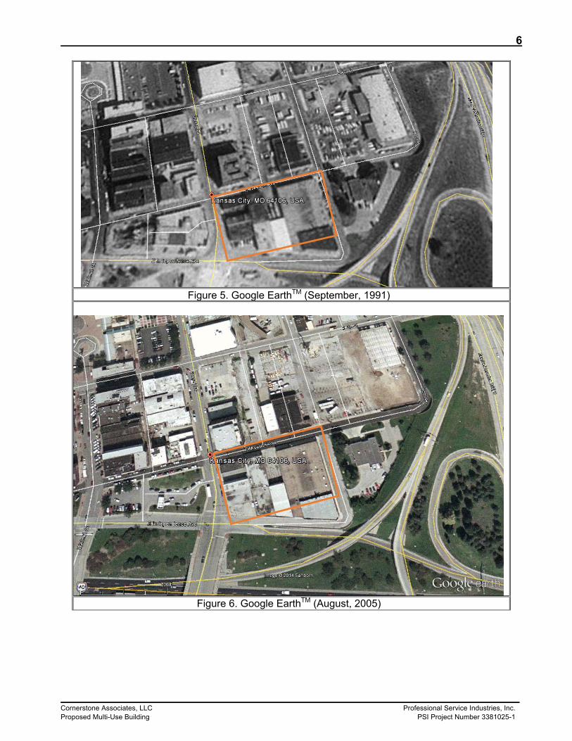
History of Site Based on historical images obtained from Google EarthTM , the site was previously occupied with a multiple structures on the east and portions as shown in figures 5 and 6. The structures were demolished circa 2007 and 2008. Figures 5 through 8 show the time line of the site from 1991 to 2014.
6
Cornerstone Associates, LLC Professional Service Industries, Inc. Proposed Multi-Use Building PSI Project Number 3381025-1
Figure 5. Google EarthTM (September, 1991)
Figure 6. Google EarthTM (August, 2005)
7
Cornerstone Associates, LLC Professional Service Industries, Inc. Proposed Multi-Use Building PSI Project Number 3381025-1
Figure 7. Google EarthTM (March 2008)
Figure 8. Google EarthTM (May, 2014)
8
Cornerstone Associates, LLC Professional Service Industries, Inc. Proposed Multi-Use Building PSI Project Number 3381025-1
Subsurface Conditions
The site subsurface conditions were explored with 6 preliminary soil test borings that were drilled within the proposed building area to an approximate depth of 50 feet below existing ground surface. Boring B-1 was offset and drilled at 3 locations due to shallow refusal at about 7 feet in all three boreholes as shown in the boring location plan attached to the appendix of this report. The boring locations and depths were suggested by PSI and reviewed with the client prior to drilling. The client reduced the number of borings from 8 to 6 and declined 15 feet of rock coring. PSI personnel staked the borings in the field by measuring distances from available surface features. West Portion of Site (Borings B-1, B-2, B-4, and B-5) The west portion of the site was covered with gravel surface with thickness ranging from 3 to 4 inches. The gravel surface was underlain by undocumented rubble fill that consisted of clayey materials, gravel, sand, bricks, concrete and organic soil that extended to depths ranging from 7 to 16 feet below existing grade. The standard penetration N-values within these undocumented fill materials indicate variability in material and presence of soft zone and voids. The undocumented fill materials were underlain by fine-grained soils that extended to near the terminal depth of boring. Shale materials were encountered towards the bottom of the bore holes that were generally stiff. Based on results of Atterberg limits and visual classification, these soils were classified as low plasticity clay (CL) and high plasticity clay (CH) in accordance with the Unified Soil Classification System (USCS).
Figure 9. Rubble fill encountered at boring B-5
9
Cornerstone Associates, LLC Professional Service Industries, Inc. Proposed Multi-Use Building PSI Project Number 3381025-1
East Portion of Site (Borings B-3 and B-6) The east portion of the site was covered with an organic layer with thickness ranging from 5 to 6 inches. At boring B-6, the organic layer was underlain by undocumented fill that consisted of clayey materials, bricks, and organic soil that extended to depths ranging from 17 feet below existing grade. At boring B-3, the undocumented fill consisted of clay soils that extended to an approximate depth of 10 feet. The standard penetration N-values within these undocumented fill materials indicate wide variability in material, moisture contents and the presence of soft zones and voids. The undocumented fill materials were underlain by fine-grained soils that extended to the terminal depth of boring. The stiffness of the fine-grained soils increased with depths and shale materials were encountered towards the bottom of the bore holes. In addition, trace of sand, gravel and organic soils were encountered at depths ranging from 34 to 35 feet. Based on results of Atterberg limits and visual classification, these soils were classified as low plasticity clay (CL) and high plasticity clay (CH) in accordance with the Unified Soil Classification System (USCS). The following table briefly summarizes the range of results from the field and laboratory testing programs. Please refer to the attached boring logs and laboratory data sheets for more specific information:
MULTI USE BUILDING-KANSAS CITY, MISSOURI SOIL STRATA TYPE A
ppro
xim
ate
Dep
ths
(ft.)
RANGE OF PROPERTY VALUES
Sta
ndar
d P
enet
ratio
n, N
60
Moi
stur
e C
onte
nt, %
Dry
Uni
t W
eigh
t, pc
f
Unc
onfin
ed
Com
pres
sive
S
tren
gth,
Qu
(tsf
)
Liqu
id L
imit,
%
Pla
stic
Lim
it, %
West Portion Borings B-1, B-2, B-4 and B-5 Undocumented/rubble fill ½-16 4-SSR 4-28 94 --- 43 24 Low Plasticity Clay 8½-47 WOH-10 23-34 93 0.3 37 22 Medium to High Plasticity Clay
35-50 8-27 16-24 --- --- --- ---
East Portion Borings B-3 and B-6 Undocumented/rubble fill ½-17 8-36 17-28 98 0.8 33-35 22-23 Low Plasticity Clay 10-36 8-30 12-23 104 1.6 47 22 High Plasticity Clay 35-50 10-30 17-25 --- --- --- ---
SSR= split spoon refusal WOH=weight of hammer
Auger refusal materials were encountered at boring B-1 at an approximate depth of 7 feet. PSI offset boring B-1 10 and 25 feet south and still achieved auger refusal at about 7 feet on concrete material. Auger refusal materials were not encountered within the remaining borings. Refusal is a designation applied to materials that cannot be further penetrated by the power auger with ordinary effort and is normally indicative of a very hard or very dense material, such as boulders or gravel lenses or the upper surface of bedrock. Split spoon refusal materials were encountered within the undocumented/rubble fill at boring B-5 at an approximate depth of 15 feet. Split spoon refusal materials are defined as materials that cannot be penetrated with a standard split spoon using ordinary effort (greater than 50 blows per 6 inches). The above subsurface description is of a generalized nature to highlight the major subsurface stratification features and material characteristics. The boring logs included in the Appendix should be
10
Cornerstone Associates, LLC Professional Service Industries, Inc. Proposed Multi-Use Building PSI Project Number 3381025-1
reviewed for specific information at individual boring locations. These records include soil descriptions, stratifications, penetration resistances, and locations of the samples and laboratory test data. The stratifications shown on the boring logs represent the conditions only at the actual boring locations. Variations may occur and should be expected between boring locations. The stratifications represent the approximate boundary between subsurface materials and the actual transition may be gradual. Water level information obtained during field operations is also shown on these boring logs. The samples that were not altered by laboratory testing will be retained for sixty (60) days from the date of this report and then will be discarded.
Water Level Measurements
Free water was observed in the borings and was measured at depths between 18 and 34 feet. However, it should be noted that saturated soils were generally identified during laboratory analysis at depths as shallow as 18 feet below the ground surface. The water level measurements presented in this report are the levels that were measured at the time of PSI’s field activities.
There are 3 primary preliminary geotechnical characteristics at this site, which will affect the selection and performance of the foundations for this structure. The following summarizes those concerns: 1. The shear strength and compressibility of the upper soils will control the behavior of the proposed
structure. 2. Existing undocumented urban fill materials of variable consistency were encountered within the
project area. 3. Demolition and removal of the existing loading dock structure. PSI believes that a concrete structure
is possibly buried at the western portion of the site. Shear Strength and Compressibility of Soil
The primary geotechnical property controlling the bearing capacity and compressibility of the soils bearing the applied loads is the shear strength of the soil. PSI anticipates that an engineering fill placed as recommended in the final report would have a minimum shear strength ranging from 1,200 to 1,500 psf. The undrained shear strengths of the cohesive soils are presented in the following table:
Depth of Soil Soil Type Range of Shear Strength 1 to 16 feet Undocumented/rubble fill 500 to 1,800 psf 16 to 35 feet Low plasticity clay 900 to 1,800 psf 35 to 50 feet Medium to High Plasticity Clay 1,500 to 2,500 psf
Existing Undocumented Fill
The presence of undocumented/rubble urban fill introduces a construction risk due to the potential for excessive and/or non-uniform settlement. Fill is defined as follows: Fill; Man placed soil is called fill, and the process of placing it is termed filling. One of the most common problems of earth construction is the wide variability of the source soil, termed borrow. An essential part of the geotechnical engineering report is to provide guidance for the placement of fill from a borrow source in a manner that achieves the design parameters for the project being
11
Cornerstone Associates, LLC Professional Service Industries, Inc. Proposed Multi-Use Building PSI Project Number 3381025-1
constructed. Fill is further classified by the placement process. The following lists various terms applied to fill placement practices:
1. Uncontrolled Fill; fill material that consists of soil and/or non-soil materials that has been placed in a manner that does not produce consistent density, uniform moisture content at time of placement, and in general materials of durable physical characteristics is termed an uncontrolled fill.
2. Undocumented Fill; fill material composed of soil that has not been observed by a geotechnical engineer or qualified technician under the direction of a geotechnical engineer during the actual fill placement process with physical measurements of lift thickness, dry density, moisture content at time of placement, location of tests and fill soils placed, and the methodology of placement with types of placement equipment is termed undocumented fill.
3. Engineered Fill; fill material that is placed to have specific shear strength, permeability, consolidation, or other physical parameter(s) specific to the end use of the man placed soil material. Applications include, but are not limited to, retaining wall backfill, pond and landfill liners, embankments, dams, and bridge abutments.
4. Rubble Fill; fill material composed of inconsistent materials that consist of large concrete boulders and fines. The material could be difficult to compact due to the consistency of the material. The presence of voids within the material can lead to settlement due to fine migration.
Generally, the fill materials varied in consistency and extended to depths ranging from 1 to 16 feet below ground surface. Based on soil encountered at the building borings, the standard penetration “N” values varied from weight of hammer to split spoon refusal at depths ranging from 1 to 16 feet which introduces a construction risk and potential of differential settlement.
Rubble fill shall be addressed as an undocumented and uncontrolled fill. The preferred manner and often the most likely solution to dealing with this type of material is removal and replacement. If removal of the material is not possible or feasible for some reason, the next most probable solution would be to install deep foundations and “bridge” the rubble fill. PSI suggest exploring the fill materials by a series of test pits that covers a large area of the site to obtain better knowledge of the contents of the fill materials. Test pits are typically performed using a bucket excavator that excavates a relatively larger volume as compared to traditional drilling methods. The test pits are able to be viewed in the field showing the localized macro-structure of the soil profile which cannot always be observed using traditional drilling methods due to sample size limitations. Test pits will assist in identifying the variability of the rubble fill and aid the owner in assessing their risks.
Based on PSI’s exploration at building borings and on the standard penetration “N” values, and moisture contents the fill material encountered appears to be inconsistent and possibly placed in uncontrolled manner. The owner must accept the elevated risk of non-uniform or excessive settlement if the entire or portions of the structures are supported by these materials. PSI preliminarily recommends the following options to support the structure due to fill at site:
1. Support the building on a deep foundation system consisting of deep foundation system that
extends through undocumented fill/ rubble fill and bear on native underlying soil/rock depending on final design wall and column loads.
2. For floor slab, PSI recommends that the 5 to 10 feet of fill to be removed to a minimum of 5 feet outside the building foot print and replaced in a controlled manner and should be observed and documented by a representative of the geotechnical engineer depending on
12
Cornerstone Associates, LLC Professional Service Industries, Inc. Proposed Multi-Use Building PSI Project Number 3381025-1
final floor slabs design loads. Removal of Existing Structures
PSI recommends removing the existing loading dock structure and the possible buried concrete structures. The excavations created during the demolition work should be backfilled with structural fill as recommended in the Site Preparation section of this report. Also, existing utilities that interfere with the proposed construction should be properly abandoned in-place or removed and the trenches backfilled with structural fill. It is important that the demolition of existing structures be performed with close observation and testing. Slabs and pavements might be supported on the new fill placed in the demolition excavations. The demolition contractor should be aware of the project requirements for backfilling so that later removal of these fill materials and replacement under controlled conditions is not necessary upon building construction.
PRELIMINARY GEOTECHNICAL RECOMMENDATIONS The following preliminary geotechnical related recommendations have been developed on the basis of the subsurface conditions encountered and PSI’s limited understanding of the proposed development. When final design loads, grading and other details in the project criteria are known, a review must be made by PSI to determine what modifications to our recommendations will be required. Site Preparation
It should be planned to have all vegetation, roots, asphalt, concrete, demolition debris, soft, organic, frozen, or unsuitable soils in the construction areas be stripped from the site and either wasted or stockpiled for later use in non-structural areas. A representative of the geotechnical engineer should evaluate and document the required depth of removal at the time of construction. PSI recommended overexcavating 5 feet of existing fill and replace with structural fill within the floor slab. If fill is not removed, the client must accept risk of potential settlement due to fine migration and compression of soft soils. Existing fill can be hauled off site or could be sorted and sorted material could be used as structural fill provided it meets criteria mentioned below. After stripping to the proposed subgrade level, as required, the building area should be planned to be proof-rolled with a loaded tandem axle dump truck or similar heavy rubber tired vehicle (typically with an axial load greater than nine (9) tons). Soils that are observed to rut or deflect excessively (typically greater than one (1) inch) under the moving load should be undercut and replaced with properly compacted low plasticity fill material. After subgrade preparation and observation have been completed, new fill placement required to establish final design grade may begin. Low-plasticity structural fill materials placed beneath the lightly loaded structural features or slabs should be free of organic or other deleterious materials and have a maximum particle size of less than three (3) inches. Low-plasticity soils are defined as having a liquid limit less than forty-five (45) and plasticity index less than twenty-five (25). The on-site high plasticity clay soils are suitable for use as structural fill to within 1 foot below the final grade for new pavements and 2 feet below the final subgrade for lightly loaded structures and building slabs. If high plasticity fat clays are utilized as fill, they should have a liquid limit no greater than seventy-five (75) and a plasticity index no greater than forty-five (45). A representative of PSI should be on-site to observe, test, and document the
13
Cornerstone Associates, LLC Professional Service Industries, Inc. Proposed Multi-Use Building PSI Project Number 3381025-1
placement of the fill. If the fill is too dry, water should be uniformly applied and thoroughly mixed into the soil by disking or scarifying. Close moisture content control will be required to achieve the recommended degree of compaction. Fill should be planned to be placed in maximum loose lifts of eight (8) inches and compacted to at least 95% of the materials’ standard Proctor maximum dry density, and within a range of the optimum moisture content as designated in the table below, as determined in general accordance with ASTM procedures. Each lift of compacted-engineered fill should be tested and documented by a representative of the geotechnical engineer prior to placement of subsequent lifts. The edges of compacted fill should extend a minimum of five (5) feet beyond the building footprint, or a distance equal to the depth of fill beneath the footings, whichever is greater. The measurement should be taken from the outside edge of the footing to the toe of the excavation prior to sloping. The fill placed should be planned to be tested and documented by a geotechnical technician and directed by a geotechnical engineer to evaluate the placement of fill material. It should be noted that the geotechnical engineer of record can only certify the testing that is performed and the work observed by that engineer or staff in direct report to that engineer. The fill should be evaluated in accordance with the following table:
MATERIAL TESTED PROCTOR
TYPE MIN % DRY DENSITY
PLACEMENT MOISTURE CONTENT
RANGE
FREQUENCY OF TESTING *1
Structural Lean Clay Fill* (Cohesive)
Standard 95% -1 to +3 % 1 per 2,500 ft2 of fill placed / lift
Structural Fat Clay Fill* (Cohesive)
Standard 95% 0 to +3% 1 per 2,500 ft2 of fill placed / lift
Structural Fill (Granular)* Standard 95% -2 to +2 % 1 per 2,500 ft2 of fill placed / lift
Random Fill (non load bearing)
Standard 90% -3 to +3 % 1 per 6,000 ft2 of fill placed / lift
Utility Trench Backfill Standard 95% -1 to +2 % 1 per 150 lineal foot / lift
*Structural Fill is defined as fill beneath or supporting any improvements on site such as foundation, slabs, pavements, etc. *1 Minimum 3 per lift.
The test frequency for the laboratory reference should be one laboratory Proctor or Relative Density test for every 25 field density tests for each material used on the site. If the borrow or source of fill material changes, a new reference moisture/density test should be performed. Tested fill materials that do not achieve either the required dry density or moisture content range shall be recorded, the location noted, and reported to the Contractor and Owner. A re-test of that area should be performed after the Contractor performs remedial measures.
14
Cornerstone Associates, LLC Professional Service Industries, Inc. Proposed Multi-Use Building PSI Project Number 3381025-1
Preliminary Foundation Recommendations
Due to the preliminarily high anticipated design loads and low bearing capacity of the upper soil layers, deep foundations are initially recommended for this structure. PSI has provided the following preliminary recommendations for a deep foundation system consisting of drilled piers. The borings within the building areas extended to an approximate depth of 50 feet below existing grade and refusal materials were not encountered. The following preliminary recommendations are based on the deeper soils being consistent with material encountered in bottom of the preliminary drilled borings. The table below presents the parameters used in the preliminary design of the preliminary allowable capacity of the deep foundation system based on the borings completed to date.
SOIL TYPE APPROXIMATE DEPTHS (FT)
ALLOWABLE BEARING CAPACITY (PSF)
ALLOWABLE SKIN FRICTION (PSF)
Fill 0-16 NA NA Low Plasticity Clay 16-26 NA 550 to 600
Low Plasticity Clay 26-35 2,000 to 3,500 550 to 600
Medium to High Plasticity Clay
35-50 4,500 to 7,500 800 to 1,000
Due to the high anticipated design load, PSI recommends further investigation by drilling additional final borings and rock coring within the proposed building area to determine depth and characteristics of deeper soils and rock. PSI recommend to perform further investigation at the proposed possible piers location after the design is completed and the design loads are confirmed. Based on the measured water elevations and anticipated permeability, it is likely that the piers will be constructed below ground water table, therefore; PSI recommends planning on a wet method of construction. Pier installation and depths should be observed a representative of the geotechnical engineer to document the construction conforms to the specifications and recommendations provided in the final report. Preliminary Floor Slab Recommendations
The floor slab can be grade supported on a minimum 5 to 10 feet of properly compacted low plasticity structural fill provide the owner is willing to accept the risk associated with undocumented fill. Proof-rolling, as discussed earlier in this report, should be accomplished to identify soft or unstable soils that should be removed from the floor slab area prior to fill placement and/or floor slab construction. These soils should be replaced with properly compacted structural fill as described earlier in this report. Grade supported slab structures in unheated areas shall have a minimum of 24 inches of non-frost susceptible materials to a depth of 36 inches below the exterior grade with at least 24 inches below the bottom of the slab or perimeter footings.
15
Cornerstone Associates, LLC Professional Service Industries, Inc. Proposed Multi-Use Building PSI Project Number 3381025-1
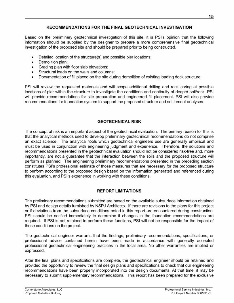
RECOMMENDATIONS FOR THE FINAL GEOTECHNICAL INVESTIGATION Based on the preliminary geotechnical investigation of this site, it is PSI’s opinion that the following information should be supplied by the designer to prepare a more comprehensive final geotechnical investigation of the proposed site and should be prepared prior to being constructed.
Detailed location of the structure(s) and possible pier locations; Demolition plan; Grading plan with floor slab elevations; Structural loads on the walls and columns; Documentation of fill placed on the site during demolition of existing loading dock structure;
PSI will review the requested materials and will scope additional drilling and rock coring at possible locations of pier within the structure to investigate the conditions and continuity of deeper soil/rock. PSI will provide recommendations for site preparation and engineered fill placement. PSI will also provide recommendations for foundation system to support the proposed structure and settlement analyses.
GEOTECHNICAL RISK The concept of risk is an important aspect of the geotechnical evaluation. The primary reason for this is that the analytical methods used to develop preliminary geotechnical recommendations do not comprise an exact science. The analytical tools which geotechnical engineers use are generally empirical and must be used in conjunction with engineering judgment and experience. Therefore, the solutions and recommendations presented in the geotechnical evaluation should not be considered risk-free and, more importantly, are not a guarantee that the interaction between the soils and the proposed structure will perform as planned. The engineering preliminary recommendations presented in the preceding section constitutes PSI’s professional estimate of those measures that are necessary for the proposed structure to perform according to the proposed design based on the information generated and referenced during this evaluation, and PSI’s experience in working with these conditions.
REPORT LIMITATIONS The preliminary recommendations submitted are based on the available subsurface information obtained by PSI and design details furnished by NSPJ Architects. If there are revisions to the plans for this project or if deviations from the subsurface conditions noted in this report are encountered during construction, PSI should be notified immediately to determine if changes in the foundation recommendations are required. If PSI is not retained to perform these functions, PSI will not be responsible for the impact of those conditions on the project. The geotechnical engineer warrants that the findings, preliminary recommendations, specifications, or professional advice contained herein have been made in accordance with generally accepted professional geotechnical engineering practices in the local area. No other warranties are implied or expressed. After the final plans and specifications are complete, the geotechnical engineer should be retained and provided the opportunity to review the final design plans and specifications to check that our engineering recommendations have been properly incorporated into the design documents. At that time, it may be necessary to submit supplementary recommendations. This report has been prepared for the exclusive
16
Cornerstone Associates, LLC Professional Service Industries, Inc. Proposed Multi-Use Building PSI Project Number 3381025-1
use of Cornerstone Associates for the specific application to the proposed Multi Use Building located near Missouri Avenue and Grand Boulevard in Kansas City, Missouri.
17
Cornerstone Associates, LLC Professional Service Industries, Inc. Proposed Multi-Use Building PSI Project Number 3381025-1
Appendix
Cornerstone Associates, LLC Professional Service Industries, Inc. Proposed Multi-Use Building PSI Project Number 3381025-1
Topographic Map
Missouri Avenue and Grand BoulevardKansas City, Missouri
Drawn By:AR
USGS Topographic MapDate: 1991 Date:
11/18/2014
PSI Project No.: 3381025Site Vicinity Map
Multi Use Building
Professional Service Industries, Inc.
N
Cornerstone Associates, LLC Professional Service Industries, Inc. Proposed Multi-Use Building PSI Project Number 3381025-1
Grading, limestone cobbles and concreterubble, stiffAuger refusal at 7 feet.
CL
25
4
7
PROJECT NO.: 338-1025PROJECT: Mixed Use Building
Dep
th,
(fee
t)
STRENGTH, tsf
AdditionalRemarks
US
CS
Cla
ssifi
catio
n
0
Qp
Sam
ple
Typ
e
2.0
0
Moi
stur
e, %
MoistureMATERIAL DESCRIPTION
STANDARD PENETRATIONTEST DATA
N in blows/ft
Qu
Sam
ple
No.
Gra
phic
Log
50
PL
Ele
vatio
n (f
eet)
LL
4.0
25
Rec
over
y (in
ches
)
N/A
While Drilling
Upon Completion
Delay
830
825
LATITUDE:LONGITUDE:
LOCATION: Missouri Ave and Grand Blvd
not observed
not observed feet
Wa
ter
REMARKS:
DRILLER: KP
Professional Service Industries, Inc.1211 W. Cambridge Circle DriveKansas City, KS 66103Telephone: (913) 310-1600 Kansas City, MO
SP
T B
low
s p
er
6-i
nch
(S
S)
SAMPLING METHOD: SS
DATE STARTED: 11/13/14
BENCHMARK: N/A
The stratification lines represent approximate boundaries. The transition may be gradual. Sheet 1 of 1
DRILL COMPANY: TSI, Inc
STATION: N/A OFFSET: 25' SE
LOGGED BY: DMWCOMPLETION DEPTH 7.0 ft DRILL RIG: CME-45
DRILLING METHOD: Hollow Stem AugerELEVATION: 832 ft
REVIEWED BY: AR
EFFICIENCY N/A See Boring Location PlanHAMMER TYPE: Automatic BORING LOCATION:
0
5
DATE COMPLETED: 11/13/14 BORING B-01
1
2
3
4
5
6
7
8
9
10
11
12
15
7
10
18
18
18
18
18
18
18
18
18
17-20-19N=39
2-4-17N=21
8-19-11N=30
5-5-5N=10
5-4-6N=10
1-3-4N=7
2-2-3N=5
3-3-3N=6
2-4-4N=8
5-9-11N=20
5-9-14N=23
6-9-12N=21
GRAVEL - 4 inchesFILL - LOW PLASTICITY CLAY, WITHBRICK, GRAVEL AND ASPHALT RUBBLE -dark brown, moist, very stiffLow plasticity clay, with rubble, dark brown
Grading, dark gray clay, firmGrading, brick rubble
Grading, low plasticity clay, with trace brick,dark grayGrading, with organics and concrete rubblebrown and dark brown,LOW PLASTICITY CLAY - brown, moist,firm
Grading, with trace gravel
HIGH PLASTICITY SANDY CLAY - brown,moist, stiff
Grading, sandy, gray brown, very stiff
Grading, shaley, gray
Boring terminated at 50 feet.
CL
CL
CH
28
21
18
19
23
23
25
25
2421
22
18
PROJECT NO.: 338-1025PROJECT: Mixed Use Building
Dep
th,
(fee
t)
STRENGTH, tsf
AdditionalRemarks
US
CS
Cla
ssifi
catio
n
0
Qp
Sam
ple
Typ
e
2.0
0
Moi
stur
e, %
MoistureMATERIAL DESCRIPTION
STANDARD PENETRATIONTEST DATA
N in blows/ft
Qu
Sam
ple
No.
Gra
phic
Log
50
PL
Ele
vatio
n (f
eet)
LL
4.0
25
Rec
over
y (in
ches
)
N/A
While Drilling
Upon Completion
Delay
835
830
825
820
815
810
805
800
795
790
LATITUDE:LONGITUDE:
LOCATION: Missouri Ave and Grand Blvd
N/A
28 feet
Wa
ter
REMARKS:
DRILLER: KP
Professional Service Industries, Inc.1211 W. Cambridge Circle DriveKansas City, KS 66103Telephone: (913) 310-1600 Kansas City, MO
SP
T B
low
s p
er
6-i
nch
(S
S)
SAMPLING METHOD: SS
DATE STARTED: 11/10/14
BENCHMARK: N/A
The stratification lines represent approximate boundaries. The transition may be gradual. Sheet 1 of 1
DRILL COMPANY: TSI, Inc
STATION: N/A OFFSET: N/A
LOGGED BY: DMWCOMPLETION DEPTH 50.0 ft DRILL RIG: CME-45
DRILLING METHOD: Hollow Stem AugerELEVATION: 836 ft
REVIEWED BY: AR South Portion of Site
EFFICIENCY N/A See Boring Location PlanHAMMER TYPE: Automatic BORING LOCATION:
LOW PLASTICITY CLAY - brown, moist,stiffLow plasticity clay, brown
Grading, with trace gravel
Grading, sandy, with gravel, and organics,very stiff
HIGH PLASTICITY SANDY CLAY - brown,moist, very stiff
Grading, shaley, gray
Boring terminated at 50 feet.
CL
CL
CH
17
21
18
21
23
23
19
22
19
25
18
18
LL = 35PL = 22
LL = 47PL = 22
DD = 104 pcfSat.=97%Qu = 1.6 tsf
PROJECT NO.: 338-1025PROJECT: Mixed Use Building
Dep
th,
(fee
t)
STRENGTH, tsf
AdditionalRemarks
US
CS
Cla
ssifi
catio
n
0
Qp
Sam
ple
Typ
e
2.0
0
Moi
stur
e, %
MoistureMATERIAL DESCRIPTION
STANDARD PENETRATIONTEST DATA
N in blows/ft
Qu
Sam
ple
No.
Gra
phic
Log
50
PL
Ele
vatio
n (f
eet)
LL
4.0
25
Rec
over
y (in
ches
)
N/A
While Drilling
Upon Completion
Delay
835
830
825
820
815
810
805
800
795
790
LATITUDE:LONGITUDE:
LOCATION: Missouri Ave and Grand Blvd
N/A
34 feet
Wa
ter
REMARKS:
DRILLER: KP
Professional Service Industries, Inc.1211 W. Cambridge Circle DriveKansas City, KS 66103Telephone: (913) 310-1600 Kansas City, MO
SP
T B
low
s p
er
6-i
nch
(S
S)
SAMPLING METHOD: SS
DATE STARTED: 11/11/14
BENCHMARK: N/A
The stratification lines represent approximate boundaries. The transition may be gradual. Sheet 1 of 1
DRILL COMPANY: TSI, Inc
STATION: N/A OFFSET: N/A
LOGGED BY: DMWCOMPLETION DEPTH 50.0 ft DRILL RIG: CME-45
DRILLING METHOD: Hollow Stem AugerELEVATION: 837 ft
REVIEWED BY: AR Southeast Portion of Site
EFFICIENCY N/A See Boring Location PlanHAMMER TYPE: Automatic BORING LOCATION:
0
5
10
15
20
25
30
35
40
45
50
DATE COMPLETED: 11/11/14 BORING B-06
>>
Cornerstone Associates, LLC Professional Service Industries, Inc. Proposed Multi-Use Building PSI Project Number 3381025-1
General Notes
GENERAL NOTES
SAMPLE IDENTIFICATION
SOIL PROPERTY SYMBOLS
SFA:
HSA:
M.R.:
R.C.:H.A.:P.A.:
DescriptionFlat:
Elongated:Flat & Elongated:
DescriptionAngular:
Subangular:
Subrounded:
Rounded:
Criteria Particles with width/thickness ratio > 3Particles with length/width ratio > 3Particles meet criteria for both flat andelongated
Descriptive TermTrace:
With:Modifier:
Size Range Over 300 mm (>12 in.)75 mm to 300 mm (3 in. to 12 in.)19 mm to 75 mm (¾ in. to 3 in.)4.75 mm to 19 mm (No.4 to ¾ in.)2 mm to 4.75 mm (No.10 to No.4)0.42 mm to 2 mm (No.40 to No.10)0.075 mm to 0.42 mm (No. 200 to No.40)0.005 mm to 0.075 mm<0.005 mm
Component Boulders:Cobbles:
Coarse-Grained Gravel:Fine-Grained Gravel:
Coarse-Grained Sand:Medium-Grained Sand:
Fine-Grained Sand:Silt:
Clay:
SS:
ST:BS:PM:
CPT-U:
ANGULARITY OF COARSE-GRAINED PARTICLESRELATIVE DENSITY OF COARSE-GRAINED SOILS
The Unified Soil Classification System (USCS), AASHTO 1988 and ASTM designations D2487 and D-2488 areused to identify the encountered materials unless otherwise noted. Coarse-grained soils are defined as havingmore than 50% of their dry weight retained on a #200 sieve (0.075mm); they are described as: boulders,cobbles, gravel or sand. Fine-grained soils have less than 50% of their dry weight retained on a #200 sieve;they are defined as silts or clay depending on their Atterberg Limit attributes. Major constituents may be addedas modifiers and minor constituents may be added according to the relative proportions based on grain size.
Standard "N" penetration: Blows per foot of a 140 pound hammer falling 30 inches on a 2-inch O.D.Split-Spoon.A "N" penetration value corrected to an equivalent 60% hammer energy transfer efficiency (ETR)Unconfined compressive strength, TSFPocket penetrometer value, unconfined compressive strength, TSFMoisture/water content, %Liquid Limit, %Plastic Limit, %Plasticity Index = (LL-PL),%Dry unit weight, pcfApparent groundwater level at time noted
Criteria Particles have sharp edges and relatively planesides with unpolished surfacesParticles are similar to angular description, but haverounded edgesParticles have nearly plane sides, but havewell-rounded corners and edgesParticles have smoothly curved sides and no edges
N:
N60:Qu:Qp:
w%:LL:PL:PI:
DD:, ,
Solid Flight Auger - typically 4" diameter flights,except where noted.Hollow Stem Auger - typically 3¼" or 4¼ I.D.openings, except where noted.Mud Rotary - Uses a rotary head with Bentoniteor Polymer SlurryDiamond Bit Core SamplerHand AugerPower Auger - Handheld motorized auger
GRAIN-SIZE TERMINOLOGY PARTICLE SHAPE
GENERAL NOTES
QU - TSF N - Blows/foot Consistency
0 - 22 - 44 - 8
8 - 1515 - 3030 - 50
50+
Criteria Absence of moisture, dusty, dry to the touchDamp but no visible waterVisible free water, usually soil is below water table
RELATIVE PROPORTIONS OF SAND AND GRAVEL % Dry Weight < 15%15% to 30%>30%
SCALE OF RELATIVE ROCK HARDNESS ROCK BEDDING THICKNESSESConsistency
Criteria Alternating layers of varying material or color withlayers at least ¼-inch (6 mm) thickAlternating layers of varying material or color withlayers less than ¼-inch (6 mm) thickBreaks along definite planes of fracture with littleresistance to fracturingFracture planes appear polished or glossy,sometimes striated
Criteria Greater than 3-foot (>1.0 m)1-foot to 3-foot (0.3 m to 1.0 m)4-inch to 1-foot (0.1 m to 0.3 m)1¼-inch to 4-inch (30 mm to 100 mm)½-inch to 1¼-inch (10 mm to 30 mm)1/8-inch to ½-inch (3 mm to 10 mm)1/8-inch or less "paper thin" (<3 mm)
Void Diameter <6 mm (<0.25 in)6 mm to 50 mm (0.25 in to 2 in)50 mm to 600 mm (2 in to 24 in)>600 mm (>24 in)
ROCK QUALITY DESCRIPTIONRQD Value
90 -10075 - 9050 - 7525 -50
Less than 25
Size Range >4.76 mm2.0 mm - 4.76 mm0.42 mm - 2.0 mm0.075 mm - 0.42 mm<0.075 mm
Rock generally fresh, joints stained and discolorationextends into rock up to 25 mm (1 in), open joints maycontain clay, core rings under hammer impact.
Rock mass is decomposed 50% or less, significantportions of the rock show discoloration andweathering effects, cores cannot be broken by handor scraped by knife.
Rock mass is more than 50% decomposed, completediscoloration of rock fabric, core may be extremelybroken and gives clunk sound when struck byhammer, may be shaved with a knife.
Rock Mass DescriptionExcellent
GoodFairPoor
Very Poor
DEGREE OF WEATHERINGSlightly Weathered:
Weathered:
Highly Weathered:
Criteria Cohesive soil that can be broken down into smallangular lumps which resist further breakdownInclusion of small pockets of different soilsInclusion greater than 3 inches thick (75 mm)Inclusion 1/8-inch to 3 inches (3 to 75 mm) thickextending through the sampleInclusion less than 1/8-inch (3 mm) thick
Very SoftSoft
Firm (Medium Stiff)Stiff
Very StiffHard
Very Hard
CLEAN SANDS
(LITTLE OR NO FINES)
SANDS WITHFINES
LIQUID LIMITLESS THAN 50
LIQUID LIMITGREATER THAN 50
HIGHLY ORGANIC SOILS
GRAVELAND
GRAVELLYSOILS
(APPRECIABLEAMOUNT OF FINES)
(APPRECIABLEAMOUNT OF FINES)
(LITTLE OR NO FINES)
FINEGRAINED
SOILS
SANDAND
SANDYSOILS
SILTSAND
CLAYS
SILTSAND
CLAYS
MORE THAN 50%OF MATERIAL ISLARGER THANNO. 200 SIEVE
SIZE
MORE THAN 50%OF MATERIAL ISSMALLER THANNO. 200 SIEVE
SIZE
MORE THAN 50%OF COARSEFRACTION
PASSING ON NO.4 SIEVE
MORE THAN 50%OF COARSEFRACTION
RETAINED ON NO.4 SIEVE
NOTE: DUAL SYMBOLS ARE USED TO INDICATE BORDERLINE SOIL CLASSIFICATIONS
OH
CH
MH
OL
CL
ML
SC
SM
SP
COARSEGRAINED
SOILS
SW
TYPICALDESCRIPTIONS
WELL-GRADED GRAVELS, GRAVEL -SAND MIXTURES, LITTLE OR NOFINES
POORLY-GRADED GRAVELS,GRAVEL - SAND MIXTURES, LITTLEOR NO FINES
SILTY GRAVELS, GRAVEL - SAND -SILT MIXTURES
LETTERGRAPHSYMBOLSMAJOR DIVISIONS
SOIL CLASSIFICATION CHART
PT
GC
GM
GP
GW
CLAYEY GRAVELS, GRAVEL - SAND -CLAY MIXTURES
WELL-GRADED SANDS, GRAVELLYSANDS, LITTLE OR NO FINES
POORLY-GRADED SANDS,GRAVELLY SAND, LITTLE OR NOFINES
SILTY SANDS, SAND - SILTMIXTURES
CLAYEY SANDS, SAND - CLAYMIXTURES
INORGANIC SILTS AND VERY FINESANDS, ROCK FLOUR, SILTY ORCLAYEY FINE SANDS OR CLAYEYSILTS WITH SLIGHT PLASTICITY
Cornerstone Associates, LLC Professional Service Industries, Inc. Proposed Multi-Use Building PSI Project Number 3381025-1
Drill, Field and Lab Testing Procedures
Drilling and Sampling Procedures
The soil borings were performed with a truck-mounted rotary head drill rig. Borings were advanced using 3¼-inch inside diameter hollow-stem augers. Representative samples were obtained employing split-spoon and thin-wall tube sampling procedures in general accordance with ASTM procedures.
Field Tests and Measurements
Penetration Tests and Split-Barrel Sampling of Soils
During the sampling procedure, Standard Penetration Tests (SPT) were performed at regular intervals (2½-foot intervals to 10 feet and 5-foot intervals thereafter) to obtain the standard penetration value (N) of the soil. The results of the standard penetration test indicate the relative density and comparative consistency of the soils, and thereby provide a basis for estimating the relative strength and compressibility of the soil profile components. The split-barrel sampler provides a soil sample for identification purposes and for laboratory tests appropriate for soil obtained from a sampler that may produce large shear strain while obtaining the sample. Thin-Walled (Shelby) Tube Geotechnical Sampling of Soils
Thin-walled tube samples are utilized to obtain a relatively undisturbed specimen suitable for laboratory tests of structural properties or other tests that might be influenced by soil properties. A relatively undisturbed sample is obtained by pressing a thin-walled metal tube (typically an outside diameter 3 inches) into the in-situ soil, removing the soil-filled tube, and sealing the ends to reduce the soil disturbance or moisture loss. These samples may be utilized in the laboratory to obtain the following information or perform the following tests: Unconfined Compressive Strength (qu), Laboratory Determination of Water Content, Wet and Dry Density, Percent Saturation, and Atterberg Limits Water Level Measurements
Water level observations were attempted during and upon completion of the drilling operation using a 100-foot tape measure. The depths of observed water levels in the boreholes are noted on the boring logs presented in the appendix of this report. In the borings where water was unable to be observed during the field activities, in relatively impervious soils, the accurate determination of the groundwater elevation may not be possible even after several days of observation. Seasonal variations, temperature and recent rainfall conditions may influence the levels of the groundwater table and volumes of water will depend on the permeability of the soils.
Laboratory Testing Program
In addition to the field investigation, a supplemental laboratory-testing program was conducted to determine additional engineering characteristics of the foundation materials necessary in analyzing the behavior of the soils as it relates to the construction of the proposed structures. The laboratory testing program is as follows:
Cornerstone Associates, LLC Professional Service Industries, Inc. Proposed Multi-Use Building PSI Project Number 3381025-1
Laboratory Determination of Water (Moisture) Content of Soil by Mass
The water content is a significant index property used in establishing a correlation between soil behavior and its index properties. The water content is used in expressing the phase relationship of air, water, and solids in a given volume of material. In fine grained cohesive soils, the behavior of a given soil type often depends on its water content. The water content of a soil along with its liquid and plastic limits as determined by Atterberg Limit testing, is used to express its relative consistency or liquidity index. Atterberg Limits
The Atterberg Limits are defined by the liquid limit (LL) and plastic limit (PL) states of a given soil. These limits are used to determine the moisture content limits where the soil characteristics changes from behaving more like a fluid on the liquid limit end to where the soil behaves more like individual soil particles on the plastic limit end. The liquid limit is often used to indicate if a soil is a low or high plasticity soil. The plasticity index (PI) is difference between the liquid limit and the plastic limit. The plasticity index is used in conjunction with the liquid limit to assess if the material will behave like a silt or clay. The material can also be classified as an organic material by comparing the liquid limit of the natural material to the liquid limit of the sample after being oven-dried. Unconfined Compressive Strength of Cohesive Soil (qu)
The primary purpose of the unconfined compressive strength test is to obtain the undrained compressive strength of soils that possess sufficient cohesion to permit testing in the unconfined state. Unconfined compressive strength (qu) is the compressive stress at which an unconfined cylindrical specimen of soil will fail in a simple compression test. In this test method, unconfined compressive strength is taken as the maximum load obtained per unit area or the load per unit area at 15% axial strain, whichever is obtained first during the performance of a test. For the unconfined compressive strength test, the shear strength (su) is calculated to be half of the compressive stress at failure. Grain Size Analysis
The purpose of determining the grain or particle size distribution of a sample is to classify and characterize the density of materials, determine the packing arrangement of the particles and estimate the shear strength and permeability of the soil matrix. To determine the grain size of coarse particles, sieves of varying opening sizes are used. Hydrometer analysis is used to determine the grain size of materials finer than sand sized particles. In addition to classification, the grain size distribution is an important for use in filter design between two materials, estimating the permeability of a soil, and liquefaction and swell potential of a soil.
Cornerstone Associates, LLC Professional Service Industries, Inc. Proposed Multi-Use Building PSI Project Number 3381025-1
Laboratory Data
0
10
20
30
40
50
60
0 20 40 60 80 100
LL
PSI Job No.:Project:Location:
338-1025Mixed Use BuildingMissouri Ave and Grand BlvdKansas City, MO
Fines
PLASTICITY
INDEX
CL
1.5
14.0
1.5
4.0
19.0
19
15
10
13
25
43
37
33
35
47
PI
CH
CL-ML
Classification (*Visual)
ML
Boring Depth (ft) PL
LIQUID LIMIT
MH
Low plasticity clay, with rubble, dark brown
Low plasticity clay, brown
Low plasticity clay, brown
Low plasticity clay, brown
Low plasticity clay, brown
B-02
B-02
B-03
B-06
B-06
Professional Service Industries, Inc.
1211 W. Cambridge Circle Drive
Kansas City, KS 66103
Telephone: (913) 310-1600
Fax: (913) 310-1601
ATTERBERG LIMIT RESULTS
24
22
23
22
22
0
5
10
15
20
25
30
35
40
45
50
55
60
65
70
75
80
85
90
95
100
0.0010.010.1110100
2
Clay Size < 0.002 mm
COBBLES
14
Specimen Identification
Specimen Identification
PI Cc
D10
41 3/4 100 140
U.S. SIEVE OPENING IN INCHES
3
D60
12.5
200
fine
GRAIN SIZE DISTRIBUTION
20 301.5
coarse medium
29.0
Classification
D100
50
67.4
6
Cu
fine
SANDSILT OR CLAY
GRAVEL
1/23/8
HYDROMETER
3
GRAIN SIZE IN MILLIMETERS
PE
RC
EN
T F
INE
R B
Y W
EIG
HT
40
U.S. SIEVE NUMBERS
4
B-03
LL PL
6 810
%Gravel %Sand %Silt %Clay
B-03
60
coarse
D30
29.0
16
32.40.2
Project:PSI Job No.:Location:
Mixed Use Building338-1025Missouri Ave and Grand BlvdKansas City, MO
Professional Service Industries, Inc.
1211 W. Cambridge Circle Drive
Kansas City, KS 66103
Telephone: (913) 310-1600
Fax: (913) 310-1601
>>>>>>
0
500
1,000
1,500
2,000
2,500
3,000
3,500
0 2 4 6 8 10 12 14
ST
RE
SS
, psf
Boring
UNCONFINED COMPRESSION TESTS
9.0
14.0
44.0
29.0 3131B-06
Depth
Boring Depth (pcf) MC%Qu
(psf)
B-03
B-03
B-04
(pcf) MC%
1671
2146
616
Qu(psf)
PSI Job No.:Project:Location:
338-1025Mixed Use BuildingMissouri Ave and Grand BlvdKansas City, MO