Preliminary Investigation of the Microstructure and Mechanical Behaviour of 2024 Aluminium Alloy Friction Spot Welds * 1 Sergio T. Amancio-Filho 1;2 , Ana P. C. Camillo 3; * 2 , Luciano Bergmann 1 , Jorge F. dos Santos 1 , Sebastia ˜o E. Kury 3 and Nelson G. A. Machado 3 1 Helmholtz-Zentrum Geesthacht, Institute of Materials Research, Materials Mechanics, Solid State Joining Processes, Max-Planck-St. 1, D-21502 Geesthacht, Germany 2 Helmholtz-Zentrum Geesthacht, Institute of Materials Research, Materials Mechanics, Advanced Polymer-Metal Hybrid Structures, Max-Planck-St. 1, D-21502 Geesthacht, Germany 3 Federal University of Sao Carlos (UFSCar), Departamento de Engenharia de Materials (DEMa), Rodovia Washington Luiz km 235, 13565-905 Sa ˜o Carlos-SP, Brazil Friction Spot Welding (FSpW) is a new solid-state joining process able to produce similar and dissimilar overlap connections in different classes of materials. Advantages of this new technique are: short production cycles, high performance joints, absence of filler materials and good surface finishing supported by material refilling in the spot area. Although few authors have addressed the microstructural and mechanical behavior of friction spot welds of Aluminum alloys, there is still a lack of a systematic evaluation on the process-properties relationship. In this work the AA2024-T3 alloy (rolled sheets) was selected for the welding procedure. Design of Experiment and Analyses of Variance techniques were employed to evaluate joint shear strength under static loading. Sound joints with elevated shear strength were achieved and the influence of the main process parameters on joint strength evaluated. [doi:10.2320/matertrans.L-MZ201126] (Received October 2, 2010; Accepted February 2, 2011; Published May 1, 2011) Keywords: aluminum alloys, friction spot welding, friction stir welding, full factorial design, friction welding 1. Introduction Friction Spot Welding (FSpW) is a new solid-state joining process developed and patented by GKSS Forschungszen- trum GmbH 1) to weld lightweight metals and thermoplastics. The principles of the technique are presented in Fig. 1. There are two process variants, the Sleeve-Plunge (SP) and the Pin- Plunge (PP) operation modus. 2) In both variants the joining partners are initially fixed in the welding machine (Fig. 1(A)). Sleeve and pin start to rotate in the same direction under a pre-set speed. Following that, either the sleeve (in the SP modus, Fig. 1(B)) or the pin (in the PP modus, Fig. 1(E)) is forced against the upper joining partner generating frictional heat. A volume of plasticized metal is formed around the rotating tool piece. In the SP variant (Fig. 1(B)), the pin is concomitantly retracted during sleeve plunging; it creates a cavity to where the plasticized metal will flow in. When a pre-determine plunge depth is reached, the sleeve is retracted backwards and the pin towards to their original position (Fig. 1(C)); this will force the plasticized metal entrapped in the formed cavity to refill the key-hole left by the sleeve. By the end of the welding cycle the tool is retracted and the joint formed (Fig. 1(D)). In the PP modus (Fig. 1(E)) the tool cavity is resultant from the retraction of sleeve while the pin is inserted into the joining partners. The other steps are equal to the SP modus. Welds obtained through the SP modus are larger then the PP modus welds, leading to stronger joints. 3) On the other hand the Pin-plunge variant is easier to perform since it demands less power associated with lower frictional forces. 4) The FSpW is able to produce similar and dissimilar overlap connections in different classes of materials, such as aluminum, magnesium, steel and thermoplastics. The FSpW (also known as Refill Friction Stir Spot Welding) was conceived aiming to avoid or decrease some limitations usually observed at other spot-like joining technologies, such as found at FSSW, such as weight penalty, difficult of automation, requirement for sealants and corrosion problems in mechanical fastening 5–8) and the presence of a key-hole a limitation found in the Friction Stir Spot Welding. Other advantages of this solid-state welding technology are absence of defects associated with conventional fusion welding techniques such as Resistance Spot (RSW) and Laser Spot Welding (LSW). For instance the fusion welding of high strength aluminum alloys is limited by the presence of the oxide/hydroxide which has higher melting temperatures and lower thermal conductivity than the metal substrate. In this case higher thermal energies are required to break up the oxide layer to melt down the substrate; this can induce alloy elements evaporation leading to properties degradation. Furthermore hydrogen cracking can take place during welding consolidation. 2) FSpW also consumes less energy in comparison to other fusion welding processes. Moreover, friction spot welds have good surface finishing (absence of key-holes or large weld beads) resulting in improved mechanical behavior. 9) Design of Experiments (DOE) is a powerful statistical tool often in industrial process optimization and analysis. The most popular DOE approaches used in welding were addressed by Benyounis and Olabi. 10) Designs commonly used are the Central Composite Design (CCD), the Response Surface Method (RSM), the Full-Factorial Design (FFD) and the Taguchi Method. The FFD is frequently selected for welding processes due to its short computational time regular experimental domain, * 1 The Paper Contains Partial Overlap with the ICAA12 Proceedings by USB under the Permission of the Editorial Committee. * 2 Graduate Student, Federal University of Sao Carlos (UFSCar) Materials Transactions, Vol. 52, No. 5 (2011) pp. 985 to 991 Special Issue on Aluminium Alloys 2010 #2011 The Japan Institute of Light Metals
Transcript
Preliminary Investigation of the Microstructure and Mechanical Behaviour
of 2024 Aluminium Alloy Friction Spot Welds*1
Sergio T. Amancio-Filho1;2, Ana P. C. Camillo3;*2, Luciano Bergmann1,Jorge F. dos Santos1, Sebastiao E. Kury3 and Nelson G. A. Machado3
1Helmholtz-Zentrum Geesthacht, Institute of Materials Research, Materials Mechanics, Solid State Joining Processes,Max-Planck-St. 1, D-21502 Geesthacht, Germany2Helmholtz-Zentrum Geesthacht, Institute of Materials Research, Materials Mechanics, Advanced Polymer-Metal Hybrid Structures,Max-Planck-St. 1, D-21502 Geesthacht, Germany3Federal University of Sao Carlos (UFSCar), Departamento de Engenharia de Materials (DEMa),Rodovia Washington Luiz km 235, 13565-905 Sao Carlos-SP, Brazil
Friction Spot Welding (FSpW) is a new solid-state joining process able to produce similar and dissimilar overlap connections in differentclasses of materials. Advantages of this new technique are: short production cycles, high performance joints, absence of filler materials and goodsurface finishing supported by material refilling in the spot area. Although few authors have addressed the microstructural and mechanicalbehavior of friction spot welds of Aluminum alloys, there is still a lack of a systematic evaluation on the process-properties relationship. In thiswork the AA2024-T3 alloy (rolled sheets) was selected for the welding procedure. Design of Experiment and Analyses of Variance techniqueswere employed to evaluate joint shear strength under static loading. Sound joints with elevated shear strength were achieved and the influence ofthe main process parameters on joint strength evaluated. [doi:10.2320/matertrans.L-MZ201126]
(Received October 2, 2010; Accepted February 2, 2011; Published May 1, 2011)
Friction Spot Welding (FSpW) is a new solid-state joiningprocess developed and patented by GKSS Forschungszen-trum GmbH1) to weld lightweight metals and thermoplastics.The principles of the technique are presented in Fig. 1. Thereare two process variants, the Sleeve-Plunge (SP) and the Pin-Plunge (PP) operation modus.2) In both variants the joiningpartners are initially fixed in the welding machine(Fig. 1(A)). Sleeve and pin start to rotate in the samedirection under a pre-set speed. Following that, either thesleeve (in the SP modus, Fig. 1(B)) or the pin (in the PPmodus, Fig. 1(E)) is forced against the upper joining partnergenerating frictional heat. A volume of plasticized metal isformed around the rotating tool piece. In the SP variant(Fig. 1(B)), the pin is concomitantly retracted during sleeveplunging; it creates a cavity to where the plasticized metalwill flow in. When a pre-determine plunge depth is reached,the sleeve is retracted backwards and the pin towards to theiroriginal position (Fig. 1(C)); this will force the plasticizedmetal entrapped in the formed cavity to refill the key-hole leftby the sleeve. By the end of the welding cycle the tool isretracted and the joint formed (Fig. 1(D)).
In the PP modus (Fig. 1(E)) the tool cavity is resultantfrom the retraction of sleeve while the pin is inserted intothe joining partners. The other steps are equal to the SPmodus. Welds obtained through the SP modus are largerthen the PP modus welds, leading to stronger joints.3) Onthe other hand the Pin-plunge variant is easier to performsince it demands less power associated with lower frictionalforces.4)
The FSpW is able to produce similar and dissimilaroverlap connections in different classes of materials, such asaluminum, magnesium, steel and thermoplastics. The FSpW(also known as Refill Friction Stir Spot Welding) wasconceived aiming to avoid or decrease some limitationsusually observed at other spot-like joining technologies, suchas found at FSSW, such as weight penalty, difficult ofautomation, requirement for sealants and corrosion problemsin mechanical fastening5–8) and the presence of a key-hole alimitation found in the Friction Stir Spot Welding. Otheradvantages of this solid-state welding technology are absenceof defects associated with conventional fusion weldingtechniques such as Resistance Spot (RSW) and Laser SpotWelding (LSW). For instance the fusion welding of highstrength aluminum alloys is limited by the presence of theoxide/hydroxide which has higher melting temperatures andlower thermal conductivity than the metal substrate. In thiscase higher thermal energies are required to break up theoxide layer to melt down the substrate; this can induce alloyelements evaporation leading to properties degradation.Furthermore hydrogen cracking can take place duringwelding consolidation.2) FSpW also consumes less energyin comparison to other fusion welding processes. Moreover,friction spot welds have good surface finishing (absence ofkey-holes or large weld beads) resulting in improvedmechanical behavior.9)
Design of Experiments (DOE) is a powerful statistical tooloften in industrial process optimization and analysis. Themost popular DOE approaches used in welding wereaddressed by Benyounis and Olabi.10) Designs commonlyused are the Central Composite Design (CCD), the ResponseSurface Method (RSM), the Full-Factorial Design (FFD) andthe Taguchi Method.
The FFD is frequently selected for welding processes dueto its short computational time regular experimental domain,
*1The Paper Contains Partial Overlap with the ICAA12 Proceedings by
USB under the Permission of the Editorial Committee.*2Graduate Student, Federal University of Sao Carlos (UFSCar)
Materials Transactions, Vol. 52, No. 5 (2011) pp. 985 to 991Special Issue on Aluminium Alloys 2010#2011 The Japan Institute of Light Metals
the possibility of modeling responses (weld properties), highaccuracy and easy understanding. The FFD is most adequatein situations where a reduced number of parameters can beselected. In welding this scenario can be found when theinitial trials were able to allow the identification of the mostimportant process parameters, such as for FSpW. Casalino11)
successfully applied a FFD to analyze the influence ofprocessing on the weld penetration in MIG-CO2 welds. Olabiet al.12) used a 3k FFD, RSM and Taguchi designs in order tominimize the residual stresses in laser welded structures.Lakshminarayanan and Balasubramanian13) applied Taguchidesigns in order to investigate the influence of rotationalspeed, welding speed and axial force on the tensile propertiesof Al-Zn-Mg alloys. Hunt et al.14) were able to design a L-18Taguchi orthogonal array model for the investigation of thefriction stir stitch welded (an alternative spot welding processbased on the FSW) AA 6022-T4 alloy. They investigated theinfluence of 8 different factors on the weld shear strength.Their resulted pointed out that RS, JT and plunge depth had astrong influence in the weld performace. Oberembt et al.15)
carried out a preliminary statistical investigation of the PP-modus FSpW in Al 6061 alloys based on a 2k-1 Half-FractionFactorial. They investigated the influence of 7 differentprocess parameters (factors) in the lap shear tensile weldstrength and in the metallurgical changes during welding.They concluded that the welding parameters mostly influ-encing the weld strength are plunge depth, pin retract rate anddwell time. From our current knowledge there are no studiespublished addressing the SP-modus of the FSpW.
The aim of the present work was to investigate theinfluence of the rotational speed and joining time on thestrength of overlap welds on AA 2024-T3 alloy produced byFriction Spot Welding. A 3k Full Factorial Design wasselected for this purpose and the average lap shear strength ofthe joints taken as the main response. Analysis of variancewas performed to evaluate the statistical confidence of thedesigned model. Finally examples of the microstructuralchanges and failure mechanisms of the spot welds werediscussed in order to illustrate the main characteristics of thejoints investigated in this study.
2. Materials and Methods
2.1 AA 2024-T3 alloy2 mm rolled sheets were used to produce overlap joints for
lap shear testing. AA 2024-T3 alloy is a ternary Al-Cu-Mg
alloy, normally used in fuselages and other aircraft struc-tures.16) This alloy exhibits poor weldability by fusionprocesses but has been shown to be successfully welded byFSpW.2) The rolled sheets exhibit medium to good stresscorrosion resistance and good tensile strength (425 MPa).16,17)
Figure 2 presents the microstructure of the AA 2024-T3 alloyparallel to the rolling direction.
2.2 Microstructural analysis and mechanical testingMetallographic sections were extracted from the center
of the spot weld in the rolling direction. Specimens wereembedded in epoxy resin and prepared through metallo-graphic specimen preparation procedures. Polished speci-mens were etched with Kroll reagent (96 mL distilled H2O,6 mL HNO3 and 2 mL HF) for macrostructural character-ization and with Barker (200 mL distilled H2O, 5 g fluoboricacid 35%) for microstructural analysis under polarizedreflective light.
Tensile tests of base material and lap shear testing ofoverlap joints were carried out in a universal testing machineequipped with a 100 kN load cell, using a traverse speed of2 mm/min at room temperature. Specimen geometry for thetensile testing of base material was in accordance with EN89518) and for lap shear tensile testing of welds the DIN ENISO 14273 standard19) (see Fig. 3).
2.3 Welding procedure and design of experimentsapproach
Overlap spot welds were produced in a commerciallyavailable friction spot welding equipment (RPS 100, Harms-Wende, Germany). Threaded FSpW tools (fabricated out of
Fig. 2 Microstructural aspects of the as-received AA 2024-T3 alloy base
material (Barker, 200X).
Fig. 1 Scheme of the FSpW process: (A) to (D) the Sleeve-Plunge Variant and (E) to (G) the Pin-Plunge Variant.
986 S. T. Amancio-Filho et al.
UHB Marax ESR steel, material DIN 1.6358, see Fig. 3)were pre-heated to 150�C prior to weld, a procedure adoptedin order to try to approach real production conditions.Optimized welding set-up pressure of 2.8 bar, sleeve plungeof 2.5 mm (0.5 mm plunging in the inferior plate) wereselected from a preliminary work20) and kept constant, whilevarying the rotation speed (1900, 2400 and 2900 rpm) andjoining time (4.8, 5.8 and 6.8 s). Dwell time was not used inthis study.
A three-level full-factorial design of experiments (3k) withtwo factors (RS and JT) was selected for the evaluation of theUltimate Lap Shear Strength (ULSS) of the weld, with threereplicates. Table 1 summarizes the 32-full factorial designused in this work.
3. Results and Discussions
3.1 Microstructural features of AA 2024-T3 alloy over-lap joints
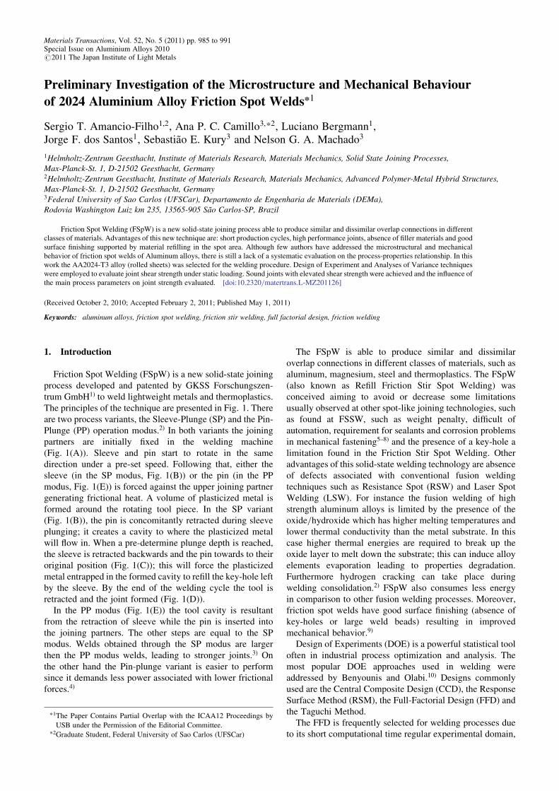
The typical microstructure of a AA 2024-T3 alloy soundjoint (1900 rpm, 4.8 s, 2.5 mm plunge) can be observed inFig. 4. Figure 4(A) presents the cross-section of this jointprior to etching. Contrary to other works, such as by Tieret al.21) and Silva et al.9) overlap joints produced in this studydid not present a well defined bond ligament, typical ofaluminum friction spot connections. This suggests thepresence of an improved material mixing observed in therange of the studied welding parameters.
The transition between the Thermo-Mechanically AffectedZone, TMAZ (characterized by a 90 degree rotation of thebase material grains due to tool stirring22)) and the Stir Zone,SZ (the region in the center of the spot with fine dynamicrecrystallized grains, originated by the high shear rates andprocess temperature22)) can be observed in Fig. 4(B) and4(D). From Fig. 4(C) the absence of refilling defects and asharp transition between the very fine grain structure of theStir Zone and the partially recrystallized grains of the TMAZ
can be seen by optical contrast (non-etched specimen). Thepresence of the so-called ‘‘hook’’ characterized by thedeviation of the non-welded interface line is presented inFig. 4(E). The hook is usually characterized by an upwardshifting of the interface line in the TMAZ followed by adownward shifting in the SZ occasioned b the re-filling of theplasticized material in the spot weld. In the current study jointhook presents an accentuated downward shifting pattern,probably due to an improved material mixing related to theoptimized profile of the tools selected in this work. Part ofthe bonding ligament line was reveled by etching and canbe seen in Fig. 4(F) (indicated by a white arrow). This factand the presence of very fine grains produced by dynamicrecrystallization in the SZ (see Fig. 4(G)) additionallyconfirms that material mixing was improved by adequateprocessing temperatures and shear deformation rates.
Dynamic recrystallization is a typical metallurgical phe-nomena found in FSpW9) and other friction-based weldingprocesses, such as friction stir welding23) and friction stir spotwelding of aluminum alloys.24) Friction welded AA 2024alloy can experiences dynamic recrystallization at processtemperatures starting at about 50% of the alloy meltingtemperature (502–638�C16,17)) and high shear rates associatedwith rotational speeds varying from 500 to 2900 rpm.9)
In order to avoid damage of the thermocouples, processtemperatures were measured with �5 mm type K thermo-couples inserted in the HAZ of the spot welds (at 16 mm fromthe spot center and placed into the upper plate at 1 mm fromthe top surface). Maximum temperature varied within 345–398�C,20) which is approximately 50–60% of the meltingpoint of the AA 2024 alloy. Therefore average temperatureand shear deformation rates in the SZ were probably highenough to support dynamic recrystallization leading to grainrefinement in comparison to the base material (compareFigs. 2 with 4(B) and 4(D)).
3.2 Joint failure behavior under shear loadingTwo typical fracture behaviors observed in this study are
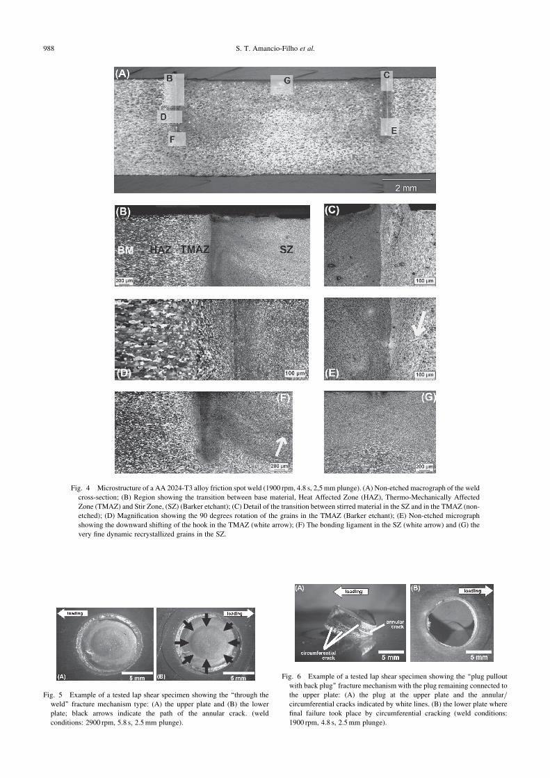
present in Figs. 5 and 6. The first mechanism (Fig. 5) wasdescribed as the ‘‘through the weld’’ fracture (TW) by Allenet al.24) This mechanism is usually associated with cata-strophic brittle fracture of the joint. Joint fails suddenly withcrack path taking place through the SZ parallel to the overlapinterface. In other types of spot welds24) this fracture type isrejected because joint shear strength is normally low. In thecase of the current joints, this sort of fracture has resulted inhigh strength and intermediate ductility (see Fig. 7). This wasalso observed by Rosendo.21) Due to the imposed stress fieldsaround the spot an annular crack (see black arrows inFig. 5(B)) will nucleate in the region near to the beginning ofthe interface shifting of the hook (a region of moderatebonding strength) and propagate to center of the stir zone in aplan parallel to the plates’ interface at the bonding ligament.
The second fracture mechanism observed is the ‘‘plugpullout with back plug’’ (PB) fracture type with the plugremaining partially connected to the upper plate24) (Fig. 6).This is a typical failure modus found in sound aluminumfriction spot joints.3) Joint exhibiting this mechanism fails ina ductile manner prior to final fracture. Shear strength is highas well as the fracture toughness of the joint, which is
Fig. 3 Scheme of the FSpW-tools used in this work.
Table 1 32-full factorial design of experiments used to evaluate FSpW
Preliminary Investigation of the Microstructure and Mechanical Behaviour of 2024 Aluminium Alloy Friction Spot Welds 987
Fig. 4 Microstructure of a AA 2024-T3 alloy friction spot weld (1900 rpm, 4.8 s, 2,5 mm plunge). (A) Non-etched macrograph of the weld
cross-section; (B) Region showing the transition between base material, Heat Affected Zone (HAZ), Thermo-Mechanically Affected
Zone (TMAZ) and Stir Zone, (SZ) (Barker etchant); (C) Detail of the transition between stirred material in the SZ and in the TMAZ (non-
etched); (D) Magnification showing the 90 degrees rotation of the grains in the TMAZ (Barker etchant); (E) Non-etched micrograph
showing the downward shifting of the hook in the TMAZ (white arrow); (F) The bonding ligament in the SZ (white arrow) and (G) the
very fine dynamic recrystallized grains in the SZ.
Fig. 6 Example of a tested lap shear specimen showing the ‘‘plug pullout
with back plug’’ fracture mechanism with the plug remaining connected to
the upper plate: (A) the plug at the upper plate and the annular/
circumferential cracks indicated by white lines. (B) the lower plate where
final failure took place by circumferential cracking (weld conditions:
1900 rpm, 4.8 s, 2.5 mm plunge).
Fig. 5 Example of a tested lap shear specimen showing the ‘‘through the
weld’’ fracture mechanism type: (A) the upper plate and (B) the lower
plate; black arrows indicate the path of the annular crack. (weld
conditions: 2900 rpm, 5.8 s, 2.5 mm plunge).
988 S. T. Amancio-Filho et al.
characterized by a large area underneath the force versusdisplacement graph (Fig. 7). Annular cracks nucleate alongwith circumferential cracks usually at the TMAZ in the hookportion. However annular crack propagation does not followthe bonding ligament path as in the case of TW failure;overall bonding ligament strength in this case is high enoughto induce the nucleation of the circumferential cracking,normally at the tip of the annular crack. Circumferentialcracks will propagate in a perpendicular plan through thethickness of the plates (Fig. 6(A)). Final joint failure takesplace around the spot as shown in Fig. 6(B). Both annularand circumferential cracks occur in regions subjected totensile stresses. For a complete description of failuresmechanisms in FSpW connections please refer to.22)
3.3 Influence of the welding parameters on the jointstrength
The 32-FFD was selected in this work for evaluating allinteractions and main factors without aliasing concerns.Furthermore this study served as a base for the selection ofoptimized joints for a complementary investigation on thecorrosion properties (to be published in a separate manu-script).
The Analysis of Variance for the general linear modeldesigned in this work is given in Table 2 for an � ¼ 0:05 (oran interval of confidence of 95%). Low p-values (p < 0:05)and high T-values for the RS and JT as well as for the secondgrade interaction RS�JT indicate that the model is statisti-cally coherent. This is additionally confirmed by the goodcorrelation coefficient R2 ¼ 0:98. However RS seems to havethe lowest influence on the response ULSS (p-value is near tothe p ¼ 0:05). This can be observed by the contribution ofthe RS of about 1.2% in comparison the contribution of themodel error of about 2.2%.
The main effect for the mean ULSS is presented in Fig. 8.If on one hand the reduced contribution of the RS on ULSS isrepresented by the flatter curve profile (Fig. 8(A)), on theother hand the importance of the JT to the ULSS is confirmedonce more by the steep increase in ULSS with JT (Fig. 8(B)).Although the effect of the RS on joint strength is notremarkable, plots of Fig. 8 suggests increasing both factors in
order to achieve stronger joints in the investigated range ofwelding parameters. However increases in JT at values aboveintermediate levels (JT > 5:8 s) seems to be prejudicial tojoint strength.
The first order interaction between RS and JT in terms ofthe mean ULSS is shown in Fig. 9. Since the curves for the1900 rpm and 2400 rpm are quite parallel those plots donot show any remarkable interaction within 4.8 to 6.8 s.Nevertheless RS and JT appears to interact at higher valuesof RS (the curve for 2900 rpm substantially deviates fromthe behavior of 1900 and 2400 rpm at 4.8 and 6.8 s). It is
Fig. 7 Example of force vs. displacement curve observed during the lap
shear testing of joints failing by TW and PB mechanisms. The curve for
the TW specimens is correspondent to the joint in Fig. 5. The curve for the
PB specimen is relative to the joint in Fig. 6.
Table 2 Analysis of variance for the response ultimate lap shear strength.
Fig. 8 Main effect plots of rotational speed (A) and joining time (B) on the
mean ultimate lap shear strength (ULSS). The horizontal reference line is
referred to the average value of all observations in all factor levels in the
experiment (avg. ULSS = 9.0 kN). The points in (A) and (B) are the
means of ULSS at the various levels of each factor (calculated from
Table 3).
Fig. 9 Effects of the interaction between rotational speed and joining time
on the mean ultimate lap shear strength (ULSS).
Preliminary Investigation of the Microstructure and Mechanical Behaviour of 2024 Aluminium Alloy Friction Spot Welds 989
probably associated with the changes in the heat input regimerelated to variations in the frictional heating. It can be betterunderstood for the lower and upper JT-values. At 4.8 s anincreases in RS will lead to higher values in ULSS because ofmore heat is being generate by friction; this was observed bySu et al.25) in friction stir spot welding, in which heatgeneration is similar to the FSpW. They modeled that RS,Torque and Joining Time are directly proportional to heatinput. In this way larger welds can be created with theselection of larger rotation speeds at constant time andjoining forces. At larger JT-values, heating efficiency isalready large; further increases in RS can lead to a decreasein Torque associated with a decrease in the plasticizedmaterial viscosity (occasioned by the increase in temper-ature). Therefore a drop in the heating generation efficiencycan take place due to the slipping of the tool and theplasticized metal. This is a common phenomenon observedin friction stir welding known sometimes as the slip/sticktransition.26) Decreases in heat generation will lead to smallerwelded areas and consequently weaker welds as it wasobserved for increases in RS at the highest JT-values (6.8 s).The geometrical changes of the investigated spot welds werediscussed elsewhere.27) Finally, Figs. 8 and 9 indicate that thehighest weld strengths with can be achieved when workingwith intermediate RS and JT .
Table 3 presents the average experimental results for theaverage ULSS in this study. The ULSS varied from about6 kN (Condition 1–1900 rpm and 4.8 s) to 10 kN (Condition6–2400 rpm and 6.8 s) with a standard deviation of 0.1 kN.The highest standard deviation values of 0.6 and 0.3 kN wereobserved respectively for Condition 8 (2900 rpm and 5.8 s)and Condition 9. All friction spot welds investigated in thiswork presented higher average ULSS in comparison tosimilar welds produced by resistance spot welding (RSW).28)
Nevertheless, current average performance of 10 kN for AA2024-T3 alloy friction spot welds are still bellow the desiredstrength observed for 9 mm diameter riveted joints (19 kN29)).This is an indication that the FSpW of AA 2024-T3 alloyshould be further optimized on one hand if rivetingsubstitution is aspired; on the other hand FSpW coulddirectly substitute RSW of 2 mm thick plates AA 2024-T3alloy, considering that its current average ULSS is two timeshigher.
4. Conclusions
The following conclusions were driven from the currentanalysis of the full factorial design results for AA 2024-T3alloy spot welds:(1) The microstructure of the friction spot welds displayed
typical metallurgical features observed in other materi-als welded by FSpW. The welded area is mainlycomposed of very fine dynamically recrystallized grainsin the stir zone as a result of high shear rate and processtemperatures (see Section 3.1).
(2) Lap shear testing specimens investigated in this workpresented two types of failure mechanisms: ‘‘throughthe weld’’ fracture and ‘‘plug pullout with back plug’’fracture. While former mechanism is usually associatedwith catastrophic brittle failure, the later is related toductile failure. Both mechanisms resulted in highULSS. Nevertheless joints failing through ‘‘plug pulloutwith back plug’’ mechanism presented higher fracturetoughness (higher ductility) than joints failing by‘‘through the weld fracture.
(3) The generated 32 full factorial model resulted in a highlevel of statistical confidence for the investigatedresponse ULSS (low p-values, high T-values and goodcoefficient of correlation). Although both first orderfactors (RS and JT) and the second order interactionRS�JT influence the behavior of the ULSS, RS doesnot substantially changes the ULSS; JT and the RS�JT
interaction are the most important factors affecting thejoint strength of the specimens tested in this weldingparameters range.
(4) The analysis of the main effect and interaction plots ofthe designed model indicated that increases in RS willslightly increase ULSS while JT will improve thisresponse within 4.8 s to 5.8 s, and depreciate it atsome extent at 6.8 s. Furthermore, JT does not stronglyinteract with RS within the range of RS varying from1900 to 2400 rpm (curves follow a parallel pattern).This is not true for the joints produced with the highestRS of 2900 rpm, where curve deviates from thestandard behavior. At the lowest JT (4.8 s), increasingRS will lead to stronger joints due to the elevation inthermal energy generation, causing the enlargement ofthe welded area. Nevertheless at the highest JT (6.8 s),where heating efficiency is already elevate, increasesin RS will depreciate the frictional regime due to anincrease in the temperature of the plasticized metal.Material viscosity and frictional performance will bereduced due to tool slippage. As a consequence lessthermal energy is produced during the welding result-ing in smaller welded areas and reduction in theULSS.
(5) Stronger joints with lower standard deviation wereproduced when welding with intermediate JT (5.8 s)and RS (2400 rpm).
Acknowledgments
The authors would like to acknowledge the financialsupport provided by Helmholtz Association, Germany.
Table 3 Summary of the 3k-full factorial design conditions and their
average ultimate lap shear strengths.
ConditionRotational
Speed [rpm]
Joining Time
[s]
Average ULSS
[kN]
Standard
Deviation [kN]
1 1900 4.8 6.2 0.1
2 1900 5.8 9.9 0.2
3 1900 6.8 10.3 0.1
4 2400 4.8 7.0 0.1
5 2400 5.8 10.1 0.2
6 2400 6.8 10.1 0.1
7 2900 4.8 8.8 0.1
8 2900 5.8 9.8 0.6
9 2900 6.8 8.9 0.3
990 S. T. Amancio-Filho et al.
REFERENCES
1) C. Schilling and J. F. dos Santos: International Patent WO/2001/
036144, May 2005.
2) A. M. Silva, M. A. D. Tier, T. S. Rosendo, F. D. Ramos, C. C. P.
Mazzaferro, J. A. E. Mazzaferro, L. A. Bergmann, T. R. Strohaecker
and J. F. dos Santos: Buletin de Informare Documentara (I.S.I.M.) 3
(2007) 36–44.
3) T. S. Rosendo, A. M. Silva, M. A. D. Tier, F. D. Ramos, J. A. E.
Mazzaferro, C. C. P. Mazzaferro, J. F. dos Santos and T. R.
Strohaecker: Proc. XXXIII CONSOLDA—Congresso Nacional de
Soldagem, Caxias do Sul, Brazil, (October 2007).
4) J. W. Arbegast: Proc. Int. Seminar on Friction based Spot Welding
Processes, Geesthacht, Germany, (March 2007).
5) J. Varis: J. Mater. Sci. Tech. 172 (2006) 130–138.
6) L. Han, K. W. Young, A. Chrysantou and J. M. O’Sullivan: Mater.
Design 27 (2006) 1108–1113.
7) Y. S. Yang and S. H. Lee: J. Mater. Sci. Technol. 94 (1999) 151–
156.
8) Y. Zhou, S. Fukomoto, J. Peng, C. Ji and L. Brown: J. Mater. Sci.
Technol. 20 (2004) 1226–1232.
9) A. M. Silva, M. A. D. Tier, T. S. Rosendo, F. D. Ramos, J. A. E.
Mazzaferro, C. C. P. Mazzaferro, S. T. R. Strohaecker and J. F. dos
Santos: SAE Technical Paper Series, 7ATC-103 (2007).
10) K. Y. Benyounis and A. G. Olabi: Adv. Eng. Software 39 (2008) 483–
496.
11) G. Casalino: J. Mater. Process. Technol. 191 (2007) 106–110.
12) A. G. Olabi, G. Casalino, K. Y. Benyounis and A. Rotondo: Mater.
Design 28 (2007) 2295–2302.
13) A. K. Lakshminarayanan and V. Balasubramanian: Trans. Non-ferrous
Met. Soc. China 18 (2008) 548–554.
14) F. Hunt, H. Badarinarayan and K. Okamoto: SAE Technical Paper
Series, 2006-01-0970 (2006).
15) C. Oberembt, C. Allen, W. Arbegast and A. Patnaik: Proc. TMS 2007,
Annual Conference of The Minerals, Metals & Materials Society,
Friction Stir Welding and Processing IV (2007) pp. 359–368.
16) ASM International: Handbook of Aluminium & Aluminium Alloys 3rd
ed., USA (1996) p. 59.
17) ASM International: Handbook of Aluminium & Aluminium Alloys 3rd
ed., USA (1996) pp. 73–74.
18) European Standard: EN DIN 895—Qualitatssicherung in der
Schweißtechnik, Querzugversuch, Germany, (1995).
19) German Standard: DIN EN ISO 14273, Specimen dimensions and
procedure for shear testing resistance spot, seam and embossed
projection welds, Germany, (2000).
20) A. P. C. Camillo: Estudo das propriedades mecanicas e de resistencia a
corrosao da solda ponto por friccao (FSpW) em ligas de aluminio,
Internship Report, (Federal University of Sao Carlos (UFSCar), Brazil,
June 2009).
21) M. Tier, T. S. Rosendo, C. A. W. Olea, C. C. P. Mazzaferro, F. D.
Ramos, M. Bayer and J. F. dos Santos: Proc. 7th Int. Symp. on Friction
Stir Welding, Awaji Island, Japan, (May 2008).
22) T. S. Rosendo: PhD-thesis, (Federal University of Rio Grande do Sul
(UFRGS), October 2009).
23) S. T. Amancio-Filho, S. Sheikhi, J. F. dos Santos and C. Bolfarin:
J. Mater. Process. Technol. 206 (2008) 132–142.
24) C. D. Allen and W. J. Abergast: Proc. SAE International Congress,
Detroit, MI, (2005).
25) P. Su, A. Gerlich, T. H. North and G. J. Bendzsak: Sci. Tech. Weld.
Joining 11 (2006) 163–169.
26) H. B. Schmidt and J. H. Hattel: Scr. Mater. 58 (2008) 332–337.
27) A. P. C. Camillo: Internal Report, (GKSS Research Center, Geesthacht
Germany, January 2009).
28) Society of Automotive Engineering: Standard SAE AMS-W-6858—
Welding: Resistance, Spot and Seam, USA, (2000).
29) MIL Military Handbook: MIL-HDBK-5H—Metallic Materials and
Elements for Aerospace Vehicle Structures, Ch. 8 (1998) pp. 8–11.
Preliminary Investigation of the Microstructure and Mechanical Behaviour of 2024 Aluminium Alloy Friction Spot Welds 991


![Weld Metal Solidification-2-Microstructure Within Grains[1]](https://static.documents.pub/doc/80x56/55157aa24a7959f1028b5208/weld-metal-solidification-2-microstructure-within-grains1.jpg)


