ORNL/TM-2016/527 Preliminary Mark-18A (Mk-18A) Target Material Recovery Program Product Acceptance Criteria Sharon Robinson Bradley Patton September 2016 Approved for public release. Distribution is unlimited.
Transcript
ORNL/TM-2016/527
Preliminary Mark-18A (Mk-18A) Target Material Recovery Program Product Acceptance Criteria
Sharon Robinson Bradley Patton September 2016
Approved for public release. Distribution is unlimited.
DOCUMENT AVAILABILITY Reports produced after January 1, 1996, are generally available free via US Department of Energy (DOE) SciTech Connect. Website http://www.osti.gov/scitech/ Reports produced before January 1, 1996, may be purchased by members of the public from the following source: National Technical Information Service 5285 Port Royal Road Springfield, VA 22161 Telephone 703-605-6000 (1-800-553-6847) TDD 703-487-4639 Fax 703-605-6900 E-mail [email protected] Website http://www.ntis.gov/help/ordermethods.aspx Reports are available to DOE employees, DOE contractors, Energy Technology Data Exchange representatives, and International Nuclear Information System representatives from the following source: Office of Scientific and Technical Information PO Box 62 Oak Ridge, TN 37831 Telephone 865-576-8401 Fax 865-576-5728 E-mail [email protected] Website http://www.osti.gov/contact.html
This report was prepared as an account of work sponsored by an agency of the United States Government. Neither the United States Government nor any agency thereof, nor any of their employees, makes any warranty, express or implied, or assumes any legal liability or responsibility for the accuracy, completeness, or usefulness of any information, apparatus, product, or process disclosed, or represents that its use would not infringe privately owned rights. Reference herein to any specific commercial product, process, or service by trade name, trademark, manufacturer, or otherwise, does not necessarily constitute or imply its endorsement, recommendation, or favoring by the United States Government or any agency thereof. The views and opinions of authors expressed herein do not necessarily state or reflect those of the United States Government or any agency thereof.
PRELIMINARY MARK-18A (Mk-18A) TARGET MATERIAL RECOVERY PROGRAM PRODUCT ACCEPTANCE CRITERIA
Sharon Robinson Bradley Patton
Date Published: September 2016
Prepared by OAK RIDGE NATIONAL LABORATORY
Oak Ridge, TN 37831-6283 managed by
UT-BATTELLE, LLC for the
U.S. DEPARTMENT OF ENERGY under contract DE-AC05-00OR2275
iii
CONTENTS
LIST OF FIGURES ...................................................................................................................................... v LIST OF TABLES ........................................................................................................................................ v ACRONYMS AND INITIALISMS ........................................................................................................... vii ACKNOWLEDGMENTS ........................................................................................................................... ix 1. INTRODUCTION ................................................................................................................................ 1 2. TARGET INVENTORY ...................................................................................................................... 3 3. METHODOLOGY AND EVALUATIONS ......................................................................................... 5
3.2.1 Am/Cm/Ln Oxide Material ............................................................................................ 7 3.2.2 Plutonium Rich Material .............................................................................................. 13
4. PRELIMINARY TRANSPORT AND ACCEPTANCE CRITERIA ................................................. 21 4.1 CRITERIA FOR AM/CM/LN MATERIAL ............................................................................. 21
5. SUMMARY AND CONCLUSIONS ................................................................................................. 25 6. REFERENCES ................................................................................................................................... 27 APPENDIX A. ESTIMATED COMPOSITION OF MK-18A TARGETS ............................................. A-1 APPENDIX B. MK-18A TYPE A PACKAGE EVALUATION – DOSE CALCULATIONS ............... B-1 APPENDIX C. MK-18A TYPE A PACKAGE EVALUATION - TEMPERATURE AND
PRESSURE CALCULATIONS ....................................................................................................... C-1 APPENDIX D. SPECIAL FORM PRESSURIZATION CALCULATION ............................................. D-1 APPENDIX E. MK-18A PLUTONIUM RICH MATERIAL CALCULATIONS ................................... E-1
v
LIST OF FIGURES
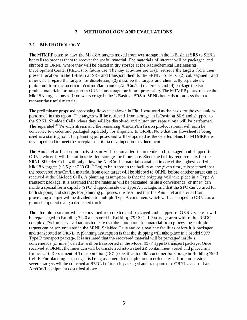
Fig. 1. Preliminary flowsheet for recovering Mk-18A material. .................................................................. 6 Fig. 2. Proposed Modified S300 Type A container for Mk-18A Am/Cm/Ln oxide shipments .................... 8 Fig. 3. Proposed Model 9977 Type B cask for Mk-18A plutonium oxide shipments. ............................... 14
LIST OF TABLES
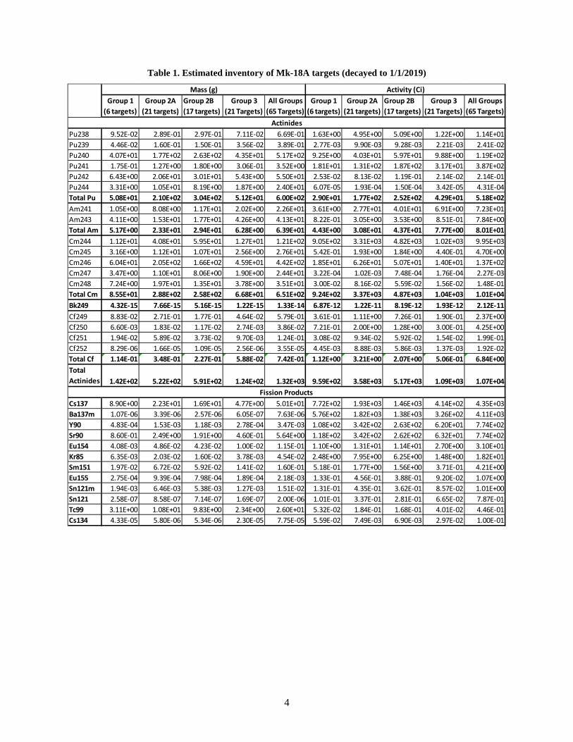
Table 1. Estimated inventory of Mk-18A targets (decayed to 1/1/2019) ...................................................... 4 Table 2. Maximum amount of Am/Cm/Ln material allowed in Type A package in special form ............... 9 Table 3. Estimated dose rates for one-third of a Group 1 Mk-18A target in Type A package in
special form ............................................................................................................................. 10 Table 4. Maximum amount of Am/Cm/Ln material allowed in Building 7920 LAA ................................ 12 Table 5. Transportation, unloading, and storage factors impacting Am/Cm/Ln material shipments ......... 13 Table 6. Minimum Actinide Content Envelop Recommended for Model 9977 Type B cask .................... 15 Table 7. Maximum amount of Pu material allowed in Building 7920 laboratory area ............................... 16 Table 8. Maximum amount of Pu material allowed in Building 7930 Cell F ............................................. 17 Table 9. Transportation, unloading, and storage factors impacting plutonium-rich material
shipments ................................................................................................................................. 19 Table 10. Transportation, unloading, and storage acceptance criteria for Am/Cm/Ln material ................. 21 Table 11. Transportation, unloading, and storage acceptance criteria for plutonium rich material ............ 22
vii
ACRONYMS AND INITIALISMS
DOE U.S. Department of Energy DOT U.S. Department of Transportation EMIS electromagnetic isotope separation FEM fissionable equivalent mass HDPE high-density polyethylene IAEA International Atomic Energy Agency IHE inhalation hazard equivalent LAA Limited Access Area MCNP Monte Carlo N-Particle (computer code) MTMRP Mk-18A Target Material Recovery Program ORIGEN-S Oak Ridge Isotope Generation in Scale (computer code) ORNL Oak Ridge National Laboratory REDC Radiochemical Engineering Development Center SAR Safety Analysis Report SARP Safety Analysis Report for Packaging SCALE Standardized Computer Analyses for Licensing Evaluation (computer code) SFC special form capsule SRNL Savannah River National Laboratory SRS Savannah River Site TRITON Time-Dependent Operation for Neutronic Depletion (computer code)
ix
ACKNOWLEDGMENTS
This work was funded by the Department of Energy National Nuclear Security Administration NA-532 Office of Nuclear Materials Integration. The work was performed by a team from Oak Ridge National Laboratory (ORNL) in conjunction with Savannah River National Laboratory/Savannah River Site (SRNL/SRS). The authors thank the many people who provided input to our analyses, including Ron Brunson, Juan Carbajo, Mike Green, Don Foster, Dan Ilas, Angie McGee, Andy Sounders, and Robin Taylor of ORNL; Sylvia McGhee of TetraTech; and Nicholas Bridges of SRNL.
1
1. INTRODUCTION
The U.S. Department of Energy (DOE) manages an inventory of materials that contains a range of long-lived radioactive isotopes that were produced from the 1960s through the 1980s by irradiating targets in production nuclear reactors at the Savannah River Site (SRS). One reactor was operated in a high-flux mode to produce heavy isotopes for defense purposes, DOE programmatic use, scientific research, and industrial and medical applications. In this reactor, eighty-six Mk-18A (Mk-18A) targets were subjected to long-term high neutron fluxes 47 years ago. Twenty-one targets of these were processed to recover 244Pu, heavy curium (i.e., curium rich in 246-248Cm), and 252Cf. The plutonium fraction, which was rich in 244Pu, was electromagnetically enriched in the Oak Ridge National Laboratory (ORNL) calutrons to produce gram quantities of 244Pu. This high-purity 244Pu was portioned out to scientists for basic research and for nuclear nonproliferation safeguards programs. The recovered tails (designated as FP-33) contain 244Pu isotopic purities below 20% and are stored at ORNL. The processing of these 21 Mk-18A targets provided the supply of 244Pu and heavy curium in use today. The remaining 65 unprocessed targets are currently in a storage pool at SRS; they contain the world’s remaining supply of unseparated 244Pu and heavy curium.
Plutonium-244 is not present in nature and is not produced in defense production or the commercial market place. Its characteristics make it irreplaceable for quantitative nuclear forensic analysis. It provides the capability to perform high-precision analysis in support of U.S. nonproliferation objectives. In addition to the 244Pu, the heavy curium in the Mk-18A targets is an attractive long-term feedstock for the production of 252Cf and other heavy elements. Although alternative feedstocks for heavy element production are available, they are less attractive than heavy curium contained in the Mk-18A targets.
The Mk-18A Target Material Recovery Program (MTMRP) was established in 2015 to preserve the unique materials in the 65 remaining Mk-18A targets for future use. This program utilizes existing capabilities at SRS and Savannah River National Laboratory (SRNL) to process targets, recover materials from them, and to package the recovered materials for shipping to ORNL. It also utilizes existing capabilities at ORNL to receive and store the recovered materials, and to provide any additional processing of the recovered materials or residuals required to prepare them for future beneficial use. The MTMRP is presently preparing for the processing of these valuable targets which is expected to begin in ~2019. As part of the preparations for operations, this report documents the preliminary acceptance criteria for the plutonium and heavy curium materials to be recovered from the Mk-18A targets at SRNL for transport and storage at ORNL. These acceptance criteria were developed based on preliminary concepts developed for processing, transporting, and storing the recovered Mk-18A materials. They will need to be refined as these concepts are developed in more detail.
3
2. TARGET INVENTORY
Eighty-six Mk-18A targets were irradiated in a high-neutron-flux mode in the K-Reactor at SRS from August 1969 to November 1970 and then irradiated in a low-flux mode until 1979. Upon removal from the reactor, 21 targets were processed at ORNL in 1972–73 to recover 252Cf, heavy curium, and plutonium. The remaining 65 targets were placed in water basin storage in the Receiving Basin for Offsite Fuels until 2001 when they were moved to their present storage location in L-Basin at SRS. The targets have been stored in their original irradiated form doubly contained in aluminum J-cans in the L-Basin at SRS since 2001.
The high neutron irradiation resulted in Mk-18A targets with unique contents. The isotopic composition of the Mk-18A targets in storage at SRS is shown in Table 1. Of particular interest are the high concentrations of 244Pu and heavy curium. The majority (>80%) of the existing global inventory of 244Pu is contained in the 65 Mk-18A targets stored at SRS. The total inventory in the Mk-18A targets is about 24 g of 244Pu in several hundred grams of plutonium, primarily 240Pu. The Mk-18A targets also contain ~650 g of heavy curium, which is ~80% of the nation’s heavy curium inventory. They also contain other valuable high-Z isotopes (e.g., 242Pu, 243Am).
The isotopic content of the 65 Mk-18A targets has been estimated by modeling the irradiation history of the Mk-18A targets in the K-Reactor using several code sequences: a Monte Carlo code developed by ORNL known as KENO, Transport Rigor Implemented with Time-Dependent Operation for Neutronic Depletion (TRITON), Oak Ridge Isotope Generation in Scale (ORIGEN-S) contained within the Standardized Computer Analyses for Licensing Evaluation (SCALE) v6.1 code package, and Monte Carlo N-Particle (MCNP) (Branney et al. 2015). The model was refined to estimate the actual data for the 21 targets processed at ORNL in the 1970s (Robinson et al. 2016) and nondestructive analysis data taken in 2015 on targets stored in the L-Basin (Branney et al. 2015). The model results compared reasonably well with these data and previous modeling results. The results were also used to estimate the isotopic contents for three subsets of targets defined by Bigford based on the irradiation history of the targets (2003). These groups included:
• Subset 1 - Six targets with high 242Pu inventory that received the most time in the active core region containing 120 g initial (prior to irradiation) 242Pu and 1.4 g 244Cm per target in 2020
• Subset 2 - 38 targets with 242Pu inventory similar to Group 1, but with more residence time in the outer zones of the reactor. This group was further divided based on their location in the reactor: – Group 2A (21 targets) - 110 g initial 242Pu and 1.6 g 244Cm per target in 2020 – Group 2B (17 targets) - 108 g initial 242Pu and 2.6 g 244Cm per target in 2020
• Subset 3 - 21 targets with residence time by reactor zone identical to Group 2, but with significantly lower 242Pu initial inventory: 6 - 32 g initial 242Pu and 0.1 - 0.8 g 244Cm per target in 2020
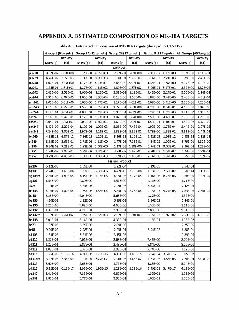
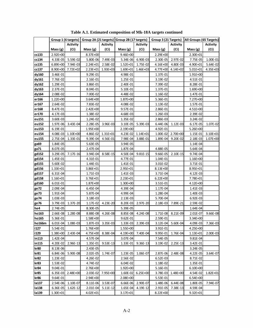
These four groups of targets were evaluated separately for each acceptance criterion to assess the impact of variability of isotopic content on the criteria. The estimated compositions are given in Appendix A, and a summary of the inventory is given in Table 1.
4
Table 1. Estimated inventory of Mk-18A targets (decayed to 1/1/2019)
The MTMRP plans to have the Mk-18A targets moved from wet storage in the L-Basin at SRS to SRNL hot cells to process them to recover the useful material. The materials of interest will be packaged and shipped to ORNL where they will be placed in dry storage at the Radiochemical Engineering Development Center (REDC) for future use. The key activities are to (1) retrieve the targets from their present location in the L-Basin at SRS and transport them to the SRNL hot cells; (2) cut, segment, and otherwise prepare the targets for dissolution; (3) dissolve the targets and chemically separate the plutonium from the americium/curium/lanthanide (Am/Cm/Ln) materials; and (4) package the two product materials for transport to ORNL for storage for future processing. The MTMRP plans to have the Mk-18A targets moved from wet storage in the L-Basin at SRS to SRNL hot cells to process them to recover the useful material.
The preliminary proposed processing flowsheet shown in Fig. 1 was used as the basis for the evaluations performed in this report. The targets will be retrieved from storage in L-Basin at SRS and shipped to the SRNL Shielded Cells where they will be dissolved and plutonium separations will be performed. The separated 244Pu -rich stream and the remaining Am/Cm/Ln fission product stream will each be converted to oxides and packaged separately for shipment to ORNL. Note that this flowsheet is being used as a starting point for planning purposes and will be updated as the detailed plans for MTMRP are developed and to meet the acceptance criteria developed in this document.
The Am/Cm/Ln fission products stream will be converted to an oxide and packaged and shipped to ORNL where it will be put in shielded storage for future use. Since the facility requirements for the SRNL Shielded Cells will only allow the Am/Cm/Ln material contained in one of the highest loaded Mk-18A targets (~3.5 g or 280 Ci 244Cm) to be stored in the facility at any given time, it is assumed that the recovered Am/Cm/Ln material from each target will be shipped to ORNL before another target can be received at the Shielded Cells. A planning assumption is that the shipping will take place in a Type A transport package. It is assumed that the material will be packaged inside a convenience (or inner) can inside a special form capsule (SFC) shipped inside the Type A package, and that the SFC can be used for both shipping and storage. For planning purposes, it is assumed that the Am/Cm/Ln material from processing a target will be divided into multiple Type A containers which will be shipped to ORNL as a ground shipment using a dedicated truck.
The plutonium stream will be converted to an oxide and packaged and shipped to ORNL where it will be repackaged in Building 7920 and stored in Building 7930 Cell F storage area within the REDC complex. Preliminary evaluations indicate that the plutonium rich material from processing multiple targets can be accumulated in the SRNL Shielded Cells and/or glove box facilities before it is packaged and transported to ORNL. A planning assumption is that the shipping will take place in a Model 9977 Type B transport package. It is assumed that the recovered material will be packaged inside a convenience (or inner) can that will be transported in the Model 9977 Type B transport package. Once received at ORNL, the inner can will be transferred into a steel 2R containment vessel and placed in a former U.S. Department of Transportation (DOT) specification 6M container for storage in Building 7930 Cell F. For planning purposes, it is being assumed that the plutonium rich material from processing several targets will be collected at SRNL before it is packaged and transported to ORNL as part of an Am/Cm/Ln shipment described above.
6
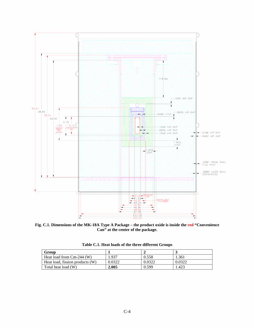
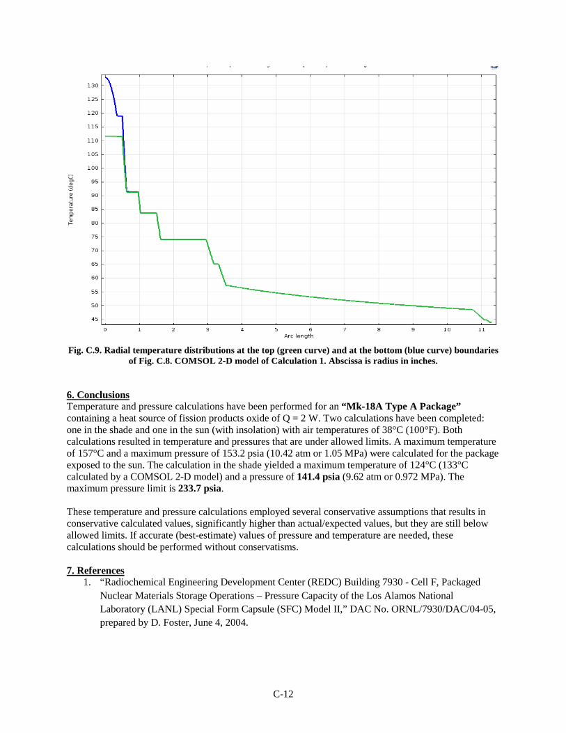
Fig. 1. Preliminary flowsheet for recovering Mk-18A material.
7
The requirements for (1) shipping materials in the Type A container in special form and Model 9977 Type B container, (2) receipt and staging the shipping containers at the proposed ORNL facilities, (3) unloading the shipping containers at the proposed ORNL facilities (and repackaging the plutonium rich material), and (4) storage of the materials in the proposed locations at ORNL were each reviewed. Purity requirements for potentially using the materials as feedstocks by programs outside the scope of the MTMRP were also considered. Each group of targets described in Section 2 was evaluated against all these requirements. The most restrictive requirements for these steps in the processing flowsheet were used to identify the preliminary acceptance criteria listed in Section 4.
3.2 EVALUATIONS
3.2.1 Am/Cm/Ln Oxide Material
The four groups of Mk-18A targets having the compositions shown in Table 1 were evaluated. It is assumed that 85% of the cesium will be removed in the caustic dissolution step at SRNL and all of the plutonium will be removed in the plutonium separation step shown in Fig. 1 prior to being converted to an oxide and packaged for shipping. Based on historical knowledge from operations at ORNL REDC, calculations used to scope the acceptance criteria assumed that the oxide powder will have a bulk density of 1.8 g/cc and a water content of ≤0.5 wt %. Note that these calculations will need to be repeated before the final acceptance criteria are developed, and these values may change as additional information becomes available.
3.2.1.1 Am/Cm/Ln Oxide Transport
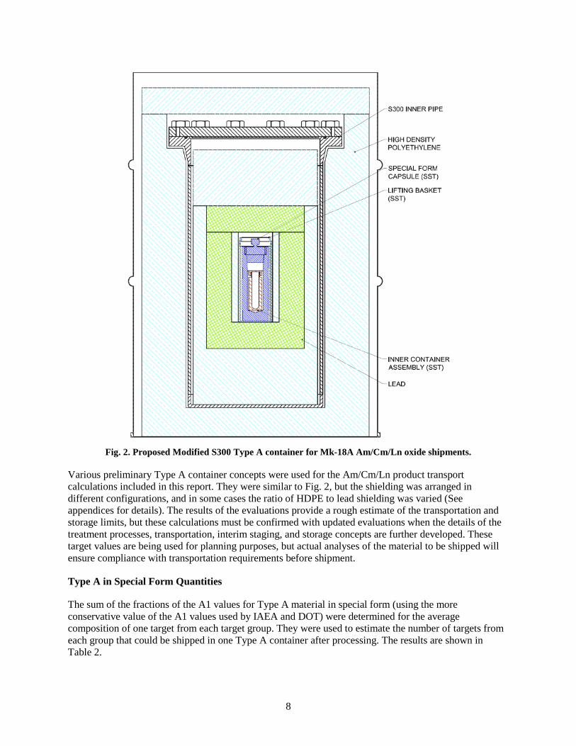
Type A containers, such as the S100 and S300, have been used to ship sealed and leaking sources and oxide powders containing alpha-emitting isotopes in special form. The general design concept for these containers is being used to design a new Type A package that will contain both gamma and neutron shielding for the Mk-18A Am/Cm/Ln material. A concept for a Modified S300 Type A container is shown in Fig. 2. It is envisioned that the unit will contain ~2.4 in. of lead shielding and ~5.4 in. high-density polyethylene (HDPE) shielding plus a 0.5-in. HDPE removable sleeve. The cavity of the container will be ~4.5 in. diameter (without the HDPE sleeve) and 8.5 in. high. It will accommodate a 2.5-in.-OD by 7-in.-tall SFC and is expected to reduce a radiation dose of ~5,000 R on the surface of the SFC to below dose limits for exclusive use domestic ground shipments. For domestic shipments, 49 CFR 173.476 allows DOE shippers to “self-certify” the special form capsule’s compliance with the development of a safety analysis in accordance with the applicable transportation regulations without a DOT International Atomic Energy Agency (IAEA) Certificate of Competent Authority being issued. It is assumed that the Type A container and the Model III SFC will be self-certified for a new content envelop that exceeds the acceptance criteria developed in this document.
8
Fig. 2. Proposed Modified S300 Type A container for Mk-18A Am/Cm/Ln oxide shipments.
Various preliminary Type A container concepts were used for the Am/Cm/Ln product transport calculations included in this report. They were similar to Fig. 2, but the shielding was arranged in different configurations, and in some cases the ratio of HDPE to lead shielding was varied (See appendices for details). The results of the evaluations provide a rough estimate of the transportation and storage limits, but these calculations must be confirmed with updated evaluations when the details of the treatment processes, transportation, interim staging, and storage concepts are further developed. These target values are being used for planning purposes, but actual analyses of the material to be shipped will ensure compliance with transportation requirements before shipment.
Type A in Special Form Quantities
The sum of the fractions of the A1 values for Type A material in special form (using the more conservative value of the A1 values used by IAEA and DOT) were determined for the average composition of one target from each target group. They were used to estimate the number of targets from each group that could be shipped in one Type A container after processing. The results are shown in Table 2.
9
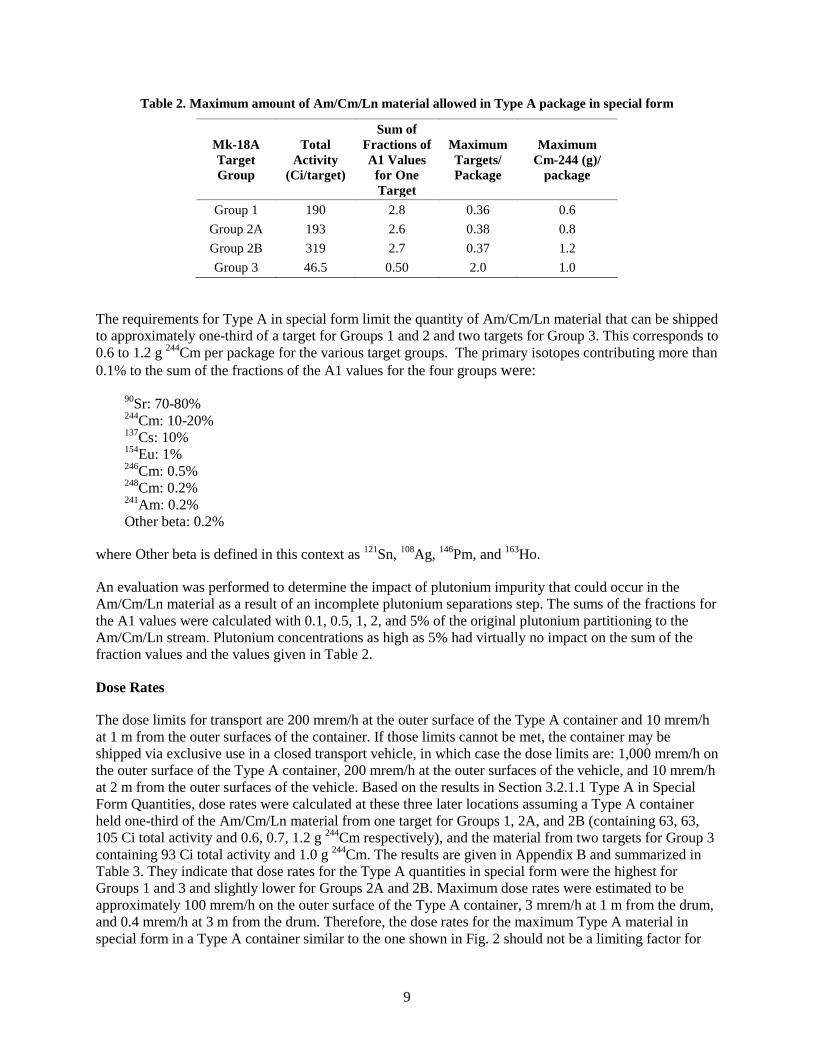
Table 2. Maximum amount of Am/Cm/Ln material allowed in Type A package in special form
Mk-18A Target Group
Total Activity
(Ci/target)
Sum of Fractions of A1 Values
for One Target
Maximum Targets/ Package
Maximum Cm-244 (g)/
package
Group 1 190 2.8 0.36 0.6 Group 2A 193 2.6 0.38 0.8 Group 2B 319 2.7 0.37 1.2 Group 3 46.5 0.50 2.0 1.0
The requirements for Type A in special form limit the quantity of Am/Cm/Ln material that can be shipped to approximately one-third of a target for Groups 1 and 2 and two targets for Group 3. This corresponds to 0.6 to 1.2 g 244Cm per package for the various target groups. The primary isotopes contributing more than 0.1% to the sum of the fractions of the A1 values for the four groups were:
where Other beta is defined in this context as 121Sn, 108Ag, 146Pm, and 163Ho.
An evaluation was performed to determine the impact of plutonium impurity that could occur in the Am/Cm/Ln material as a result of an incomplete plutonium separations step. The sums of the fractions for the A1 values were calculated with 0.1, 0.5, 1, 2, and 5% of the original plutonium partitioning to the Am/Cm/Ln stream. Plutonium concentrations as high as 5% had virtually no impact on the sum of the fraction values and the values given in Table 2.
Dose Rates
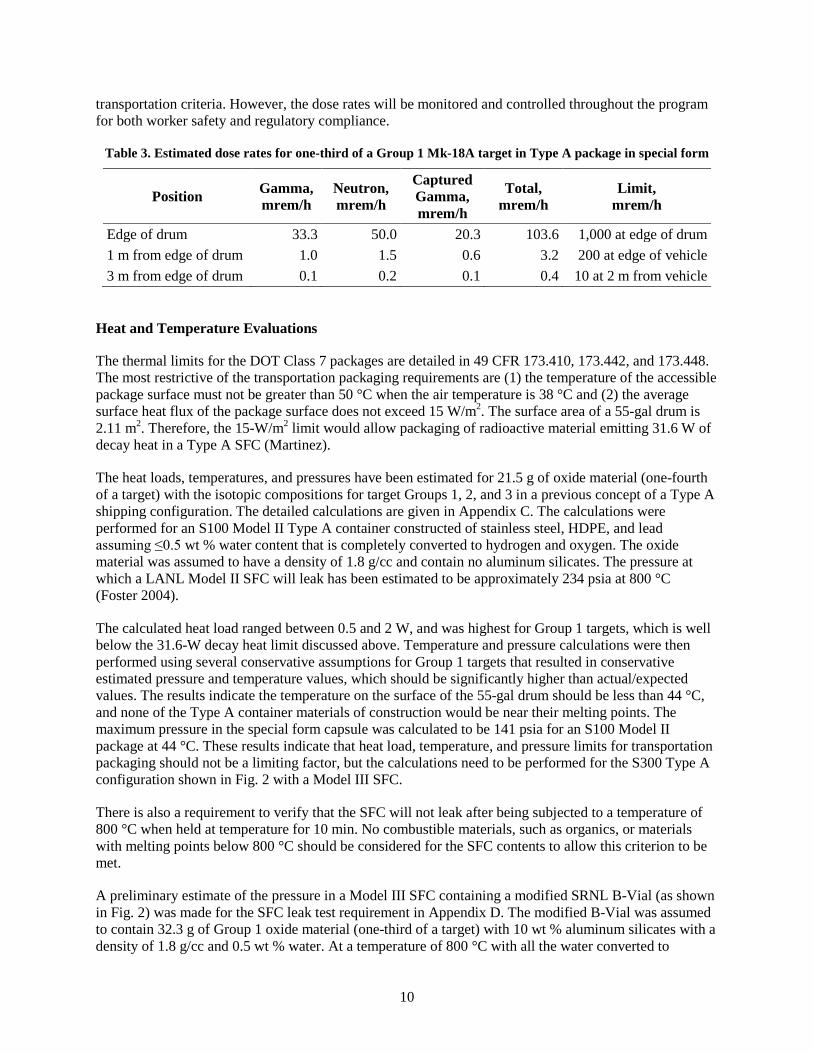
The dose limits for transport are 200 mrem/h at the outer surface of the Type A container and 10 mrem/h at 1 m from the outer surfaces of the container. If those limits cannot be met, the container may be shipped via exclusive use in a closed transport vehicle, in which case the dose limits are: 1,000 mrem/h on the outer surface of the Type A container, 200 mrem/h at the outer surfaces of the vehicle, and 10 mrem/h at 2 m from the outer surfaces of the vehicle. Based on the results in Section 3.2.1.1 Type A in Special Form Quantities, dose rates were calculated at these three later locations assuming a Type A container held one-third of the Am/Cm/Ln material from one target for Groups 1, 2A, and 2B (containing 63, 63, 105 Ci total activity and 0.6, 0.7, 1.2 g 244Cm respectively), and the material from two targets for Group 3 containing 93 Ci total activity and 1.0 g 244Cm. The results are given in Appendix B and summarized in Table 3. They indicate that dose rates for the Type A quantities in special form were the highest for Groups 1 and 3 and slightly lower for Groups 2A and 2B. Maximum dose rates were estimated to be approximately 100 mrem/h on the outer surface of the Type A container, 3 mrem/h at 1 m from the drum, and 0.4 mrem/h at 3 m from the drum. Therefore, the dose rates for the maximum Type A material in special form in a Type A container similar to the one shown in Fig. 2 should not be a limiting factor for
10
transportation criteria. However, the dose rates will be monitored and controlled throughout the program for both worker safety and regulatory compliance.
Table 3. Estimated dose rates for one-third of a Group 1 Mk-18A target in Type A package in special form
Position Gamma, mrem/h
Neutron, mrem/h
Captured Gamma, mrem/h
Total, mrem/h
Limit, mrem/h
Edge of drum 33.3 50.0 20.3 103.6 1,000 at edge of drum 1 m from edge of drum 1.0 1.5 0.6 3.2 200 at edge of vehicle 3 m from edge of drum 0.1 0.2 0.1 0.4 10 at 2 m from vehicle
Heat and Temperature Evaluations
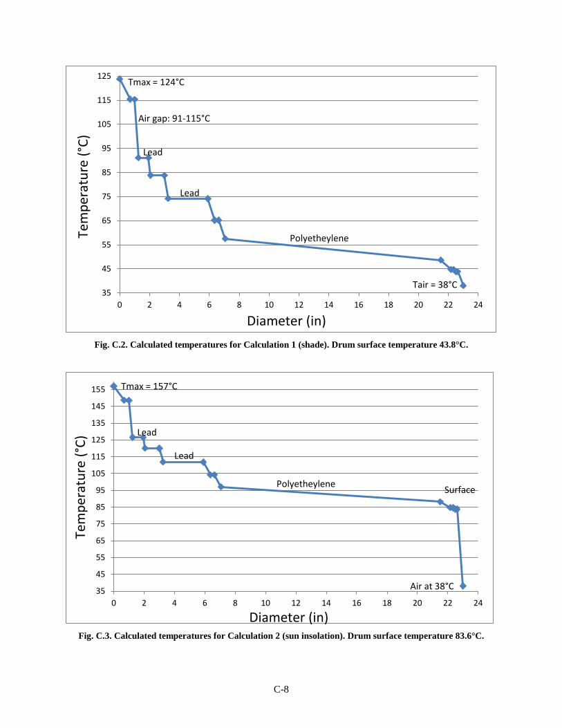
The thermal limits for the DOT Class 7 packages are detailed in 49 CFR 173.410, 173.442, and 173.448. The most restrictive of the transportation packaging requirements are (1) the temperature of the accessible package surface must not be greater than 50 °C when the air temperature is 38 °C and (2) the average surface heat flux of the package surface does not exceed 15 W/m2. The surface area of a 55-gal drum is 2.11 m2. Therefore, the 15-W/m2 limit would allow packaging of radioactive material emitting 31.6 W of decay heat in a Type A SFC (Martinez).
The heat loads, temperatures, and pressures have been estimated for 21.5 g of oxide material (one-fourth of a target) with the isotopic compositions for target Groups 1, 2, and 3 in a previous concept of a Type A shipping configuration. The detailed calculations are given in Appendix C. The calculations were performed for an S100 Model II Type A container constructed of stainless steel, HDPE, and lead assuming ≤0.5 wt % water content that is completely converted to hydrogen and oxygen. The oxide material was assumed to have a density of 1.8 g/cc and contain no aluminum silicates. The pressure at which a LANL Model II SFC will leak has been estimated to be approximately 234 psia at 800 °C (Foster 2004).
The calculated heat load ranged between 0.5 and 2 W, and was highest for Group 1 targets, which is well below the 31.6-W decay heat limit discussed above. Temperature and pressure calculations were then performed using several conservative assumptions for Group 1 targets that resulted in conservative estimated pressure and temperature values, which should be significantly higher than actual/expected values. The results indicate the temperature on the surface of the 55-gal drum should be less than 44 °C, and none of the Type A container materials of construction would be near their melting points. The maximum pressure in the special form capsule was calculated to be 141 psia for an S100 Model II package at 44 °C. These results indicate that heat load, temperature, and pressure limits for transportation packaging should not be a limiting factor, but the calculations need to be performed for the S300 Type A configuration shown in Fig. 2 with a Model III SFC.
There is also a requirement to verify that the SFC will not leak after being subjected to a temperature of 800 °C when held at temperature for 10 min. No combustible materials, such as organics, or materials with melting points below 800 °C should be considered for the SFC contents to allow this criterion to be met.
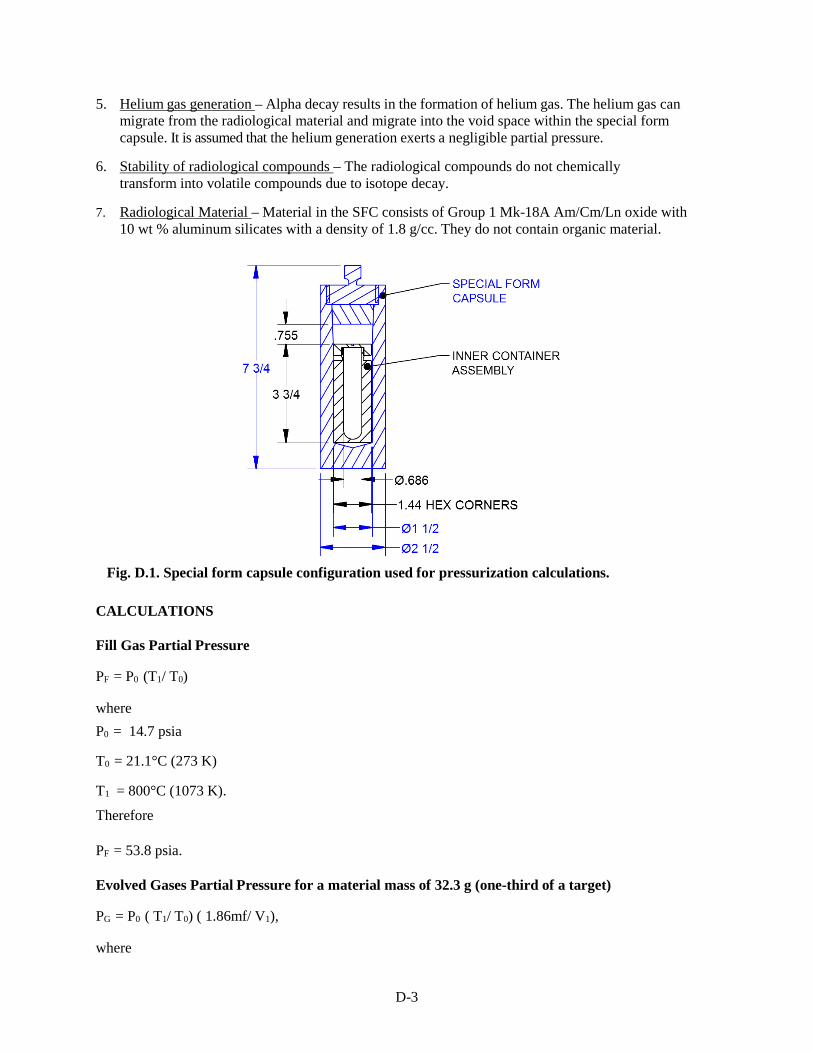
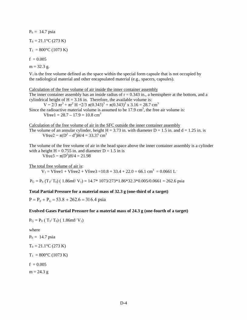
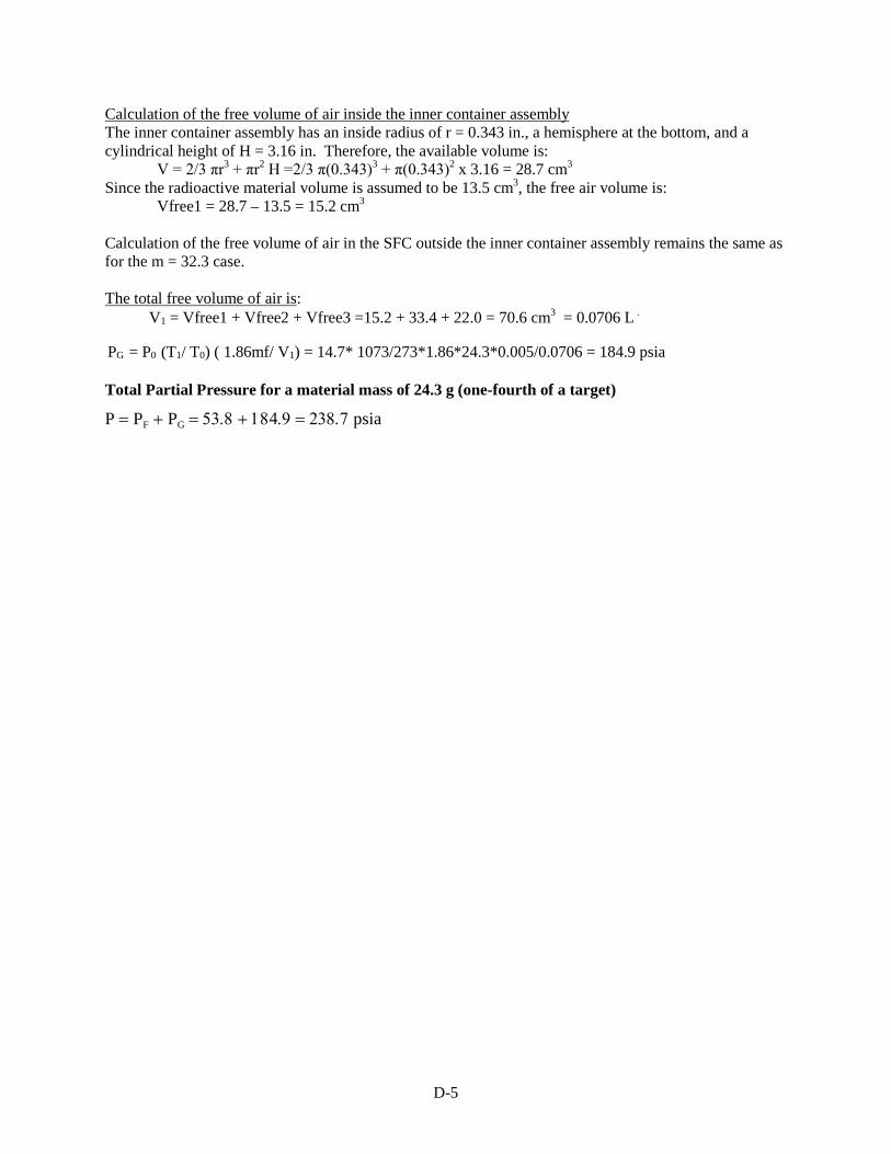
A preliminary estimate of the pressure in a Model III SFC containing a modified SRNL B-Vial (as shown in Fig. 2) was made for the SFC leak test requirement in Appendix D. The modified B-Vial was assumed to contain 32.3 g of Group 1 oxide material (one-third of a target) with 10 wt % aluminum silicates with a density of 1.8 g/cc and 0.5 wt % water. At a temperature of 800 °C with all the water converted to
11
hydrogen and oxygen, the pressure was calculated to be 316 psia. If the B-Vial contains 24 g (one-fourth a target), the pressure is estimated to be 239 psia. More detailed studies need to be performed with the final S300 Type A configuration, but this calculation indicates that the SFC leak criteria when heated to 800 °C could possibly be a limiting factor for transportation acceptance criteria. It also indicates the volume of material in the B-Vial will significantly impact these criteria. Reductions in the inert materials will increase the ability to meet the requirement by reducing the occupied volume.
3.2.1.2 Unloading/Storage Requirements
The proposed interim staging location at the REDC for the Type A packages received at ORNL from SRNL containing the Am/Cm/Ln material is a radiological facility. Preliminary evaluations indicate that a Type A package with the contents in special form can be stored in a radiological facility with no restrictions above meeting the Type A in special form criteria (DOE 1997).
The proposed storage location for the Am/Cm/Ln materials is the hot cell and/or storage pits in the Building 7920 hot cell facility at REDC. The proposed unloading plan for the Am/Cm/Ln materials is for the Type A container to be unloaded in the Limited Access Area (LAA) of Building 7920. The SFC will be removed semi-remotely and transferred into the hot cell or storage pit, and the empty Type A container will be returned to SRNL for reuse after verification that contamination limits have been met.
Dose rate calculations (see Appendix B) performed for the Type A container concept described in Section 3.2.1.1 indicate that shielding will be required to transfer the SFC from the Type A container into the hot cell. Preliminary evaluations indicate that a shield bell with 1.3-in. lead shielding and 7.23 in. HDPE shielding will reduce the dose rates to ~300 mrem/h on the outer surface of the shield, 10 mrem/h at 1 m from the shield, and 1.4 mrem/h at 3 m from the shield for an SFC containing one-third of a target from Groups 1 and 2 and two targets from Group 3. This corresponds to 0.6 to 1.2 g 244Cm per package for the various target groups. These dose levels will meet the facility requirements for worker dose for intermittent operations and should not be a limiting acceptance criterion.
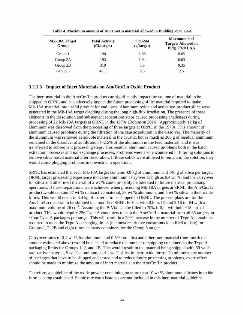
The Safety Analysis Report (SAR) for Building 7920 (ORNL, Jan. 2016) limits the quantity of radioisotopes in the LAA to 1.8 g (150 Ci) 244Cm inhalation hazard equivalents (IHE). To accommodate other activities in the facility, it is estimated that ~1.2 g (100 Ci) 244Cm from Mk-18A materials can be accommodated in the LAA at any given point in time. Table 4 compares the composition of the four target groups to this limit and indicates that approximately one third of the material from one target from Group 2B, two-thirds of a target from Groups 1 and 2A, and 2.5 targets from Group 3 could be contained in a shipment. Comparing these limits to the maximum amount of material that could be put into one package under the Type A special form requirements (Table 2), the Type A packaging requirements will be more restrictive than the Building 7920 unloading limits except for Group 2B, where they will be very similar. The results also indicate that no more than one Type A package should be located in the Building 7920 LAA at any given time. Therefore, interim staging of the multiple Type A packages expected to be received from SRNL in each shipment will be required.
12
Table 4. Maximum amount of Am/Cm/Ln material allowed in Building 7920 LAA
Mk-18A Target Group
Total Activity (Ci/target)
Cm-244 (g/target)
Maximum # of Targets Allowed in
Bldg. 7920 LAA Group 1 190 1.86 0.65
Group 2A 193 1.94 0.63 Group 2B 319 3.5 0.35 Group 3 46.5 0.5 2.5
3.2.1.3 Impact of Inert Materials on Am/Cm/Ln Oxide Product
The inert material in the Am/Cm/Ln product can significantly impact the volume of material to be shipped to ORNL and can adversely impact the future processing of the material required to make Mk-18A material into useful product for end users. Aluminum oxide and activation-product silica were generated in the Mk-18A target cladding during the long high-flux irradiation. The presence of these elements in the dissolution and subsequent separations steps caused processing challenges during processing of 21 Mk-18A targets at ORNL in the 1970s (Robinson 2016). Approximately 12 kg of aluminum was dissolved from the processing of three targets at ORNL in the 1970s. This amount of aluminum caused problems during the filtration of the caustic solution in the dissolver. The majority of the aluminum was removed as soluble material in the caustic, but as much as 300 g of residual aluminum remained in the dissolver after filtration (~2.5% of the aluminum in the feed material), and it was transferred to subsequent processing steps. This residual aluminum caused problems both in the batch extraction processes and ion exchange processes. Problems were also encountered in filtering solutions to remove silica-based material after dissolution. If these solids were allowed to remain in the solution, they would cause plugging problems in downstream operations.
SRNL has estimated that each Mk-18A target contains 4.8 kg of aluminum and 148 g of silica per target. ORNL target processing experience indicates aluminum carryover as high as 0.4 wt %, and the carryover for silica and other inert material of 2 wt % could probably be tolerated in future material processing operations. If these separations were achieved when processing Mk-18A targets at SRNL, the Am/Cm/Ln product would contain 67 wt % radioactive material, 28 wt % aluminum, and 5 wt % silica in their oxide forms. This would result in 8.4 kg of material to be shipped to ORNL. The present plans are for the Am/Cm/Ln material to be shipped in a modified SRNL B-Vial with 0.8 in. ID and 3.16 in. IH with a maximum volume of 26 cm3. Assuming the B-Vial can be filled to 70% full, it will hold ~18 cm3 of product. This would require 256 Type A containers to ship the Am/Cm/Ln material from all 65 targets, or ~four Type A packages per target. This will result in a 30% increase in the number of Type A containers required to meet the Type A packaging limits (the most restrictive constraints identified to date) for Groups 1, 2, 2B and eight times as many containers for the Group 3 targets.
Carryover rates of 0.1 wt % for aluminum and 0.5% for silica and other inert material (one-fourth the amount estimated above) would be needed to reduce the number of shipping containers to the Type A packaging limits for Groups 1, 2, and 2B. This would result in the material being shipped with 89 wt % radioactive material, 9 wt % aluminum, and 1 wt % silica in their oxide forms. To minimize the number of packages that have to be shipped and stored and to reduce future processing problems, every effort should be made to minimize the amount of inert materials in the Am/Cm/Ln product.
Therefore, a guideline of the oxide powder containing no more than 10 wt % aluminum silicates in oxide form is being established. Stable rare earth isotopes are not included in this inert material guideline.
13
3.2.1.4 Added Chemical Impurities
The hot cell equipment at ORNL Building 7920 was designed to process hydrochloric acid and nitric acid based solutions. Zircaloy-2 was selected as the material of construction for the dissolver and much of the accessory piping. Hydrofluoric acid cannot be used in the system since it is highly corrosive to the Zircaloy-2 equipment, even in amounts as small as parts per million. Therefore, no fluorides shall be added to the Am/Cm/Ln material during processing at SRNL.
3.2.1.5 Factors Controlling Am/Cm/Ln Material Acceptance Criteria
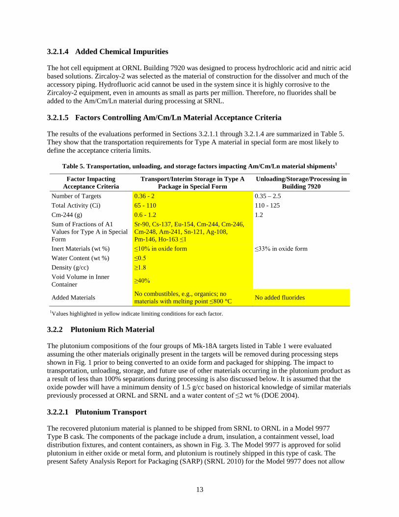
The results of the evaluations performed in Sections 3.2.1.1 through 3.2.1.4 are summarized in Table 5. They show that the transportation requirements for Type A material in special form are most likely to define the acceptance criteria limits.
Table 5. Transportation, unloading, and storage factors impacting Am/Cm/Ln material shipments1
Factor Impacting Acceptance Criteria
Transport/Interim Storage in Type A Package in Special Form
Unloading/Storage/Processing in Building 7920
Number of Targets 0.36 - 2 0.35 – 2.5 Total Activity (Ci) 65 - 110 110 - 125 Cm-244 (g) 0.6 - 1.2 1.2 Sum of Fractions of A1 Values for Type A in Special Form
Inert Materials (wt %) ≤10% in oxide form ≤33% in oxide form Water Content (wt %) ≤0.5 Density (g/cc) ≥1.8 Void Volume in Inner Container ≥40%
Added Materials No combustibles, e.g., organics; no materials with melting point ≤800 °C No added fluorides
1Values highlighted in yellow indicate limiting conditions for each factor.
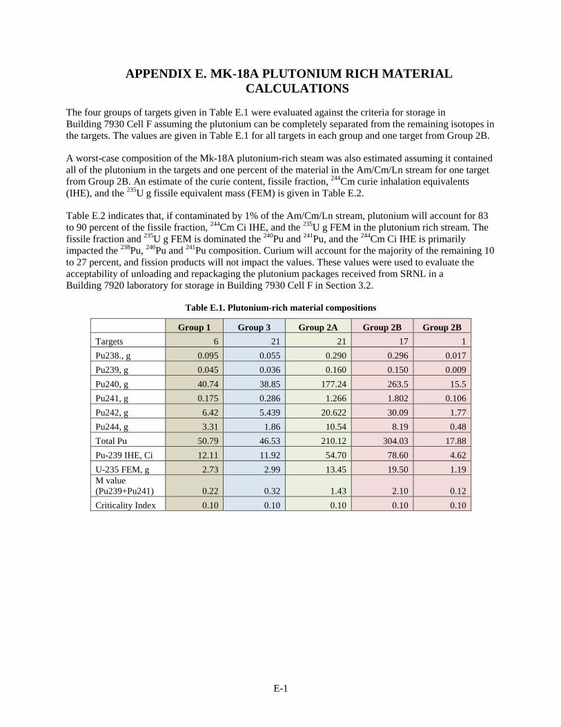
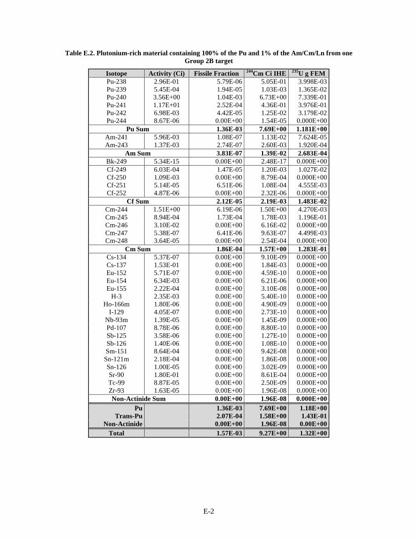
3.2.2 Plutonium Rich Material
The plutonium compositions of the four groups of Mk-18A targets listed in Table 1 were evaluated assuming the other materials originally present in the targets will be removed during processing steps shown in Fig. 1 prior to being converted to an oxide form and packaged for shipping. The impact to transportation, unloading, storage, and future use of other materials occurring in the plutonium product as a result of less than 100% separations during processing is also discussed below. It is assumed that the oxide powder will have a minimum density of 1.5 g/cc based on historical knowledge of similar materials previously processed at ORNL and SRNL and a water content of ≤2 wt % (DOE 2004).
3.2.2.1 Plutonium Transport
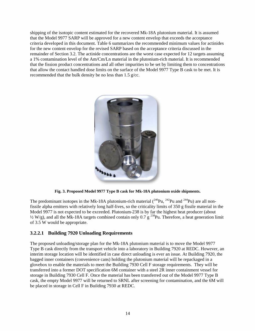
The recovered plutonium material is planned to be shipped from SRNL to ORNL in a Model 9977 Type B cask. The components of the package include a drum, insulation, a containment vessel, load distribution fixtures, and content containers, as shown in Fig. 3. The Model 9977 is approved for solid plutonium in either oxide or metal form, and plutonium is routinely shipped in this type of cask. The present Safety Analysis Report for Packaging (SARP) (SRNL 2010) for the Model 9977 does not allow
14
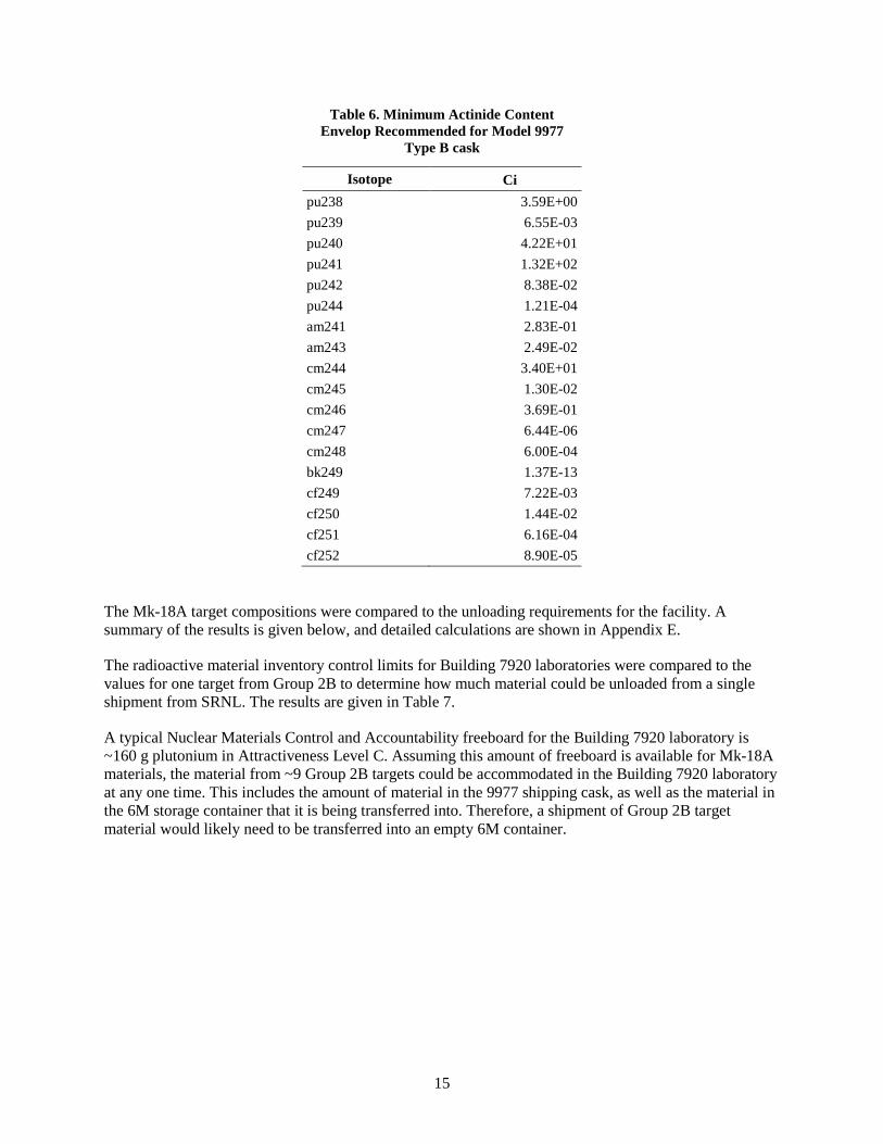
shipping of the isotopic content estimated for the recovered Mk-18A plutonium material. It is assumed that the Model 9977 SARP will be approved for a new content envelop that exceeds the acceptance criteria developed in this document. Table 6 summarizes the recommended minimum values for actinides for the new content envelop for the revised SARP based on the acceptance criteria discussed in the remainder of Section 3.2. The actinide concentrations are the worst case expected for 12 targets assuming a 1% contamination level of the Am/Cm/Ln material in the plutonium-rich material. It is recommended that the fission product concentrations and all other impurities to be set by limiting them to concentrations that allow the contact handled dose limits on the surface of the Model 9977 Type B cask to be met. It is recommended that the bulk density be no less than 1.5 g/cc.
Fig. 3. Proposed Model 9977 Type B cask for Mk-18A plutonium oxide shipments.
The predominant isotopes in the Mk-18A plutonium-rich material (240Pu, 242Pu and 244Pu) are all non-fissile alpha emitters with relatively long half-lives, so the criticality limits of 350 g fissile material in the Model 9977 is not expected to be exceeded. Plutonium-238 is by far the highest heat producer (about ½ W/g), and all the Mk-18A targets combined contain only 0.7 g 238Pu. Therefore, a heat generation limit of 3.5 W would be appropriate.
3.2.2.1 Building 7920 Unloading Requirements
The proposed unloading/storage plan for the Mk-18A plutonium material is to move the Model 9977 Type B cask directly from the transport vehicle into a laboratory in Building 7920 at REDC. However, an interim storage location will be identified in case direct unloading is ever an issue. At Building 7920, the bagged inner containers (convenience cans) holding the plutonium material will be repackaged in a glovebox to enable the materials to meet the Building 7930 Cell F storage requirements. They will be transferred into a former DOT specification 6M container with a steel 2R inner containment vessel for storage in Building 7930 Cell F. Once the material has been transferred out of the Model 9977 Type B cask, the empty Model 9977 will be returned to SRNL after screening for contamination, and the 6M will be placed in storage in Cell F in Building 7930 at REDC.
15
Table 6. Minimum Actinide Content Envelop Recommended for Model 9977
The Mk-18A target compositions were compared to the unloading requirements for the facility. A summary of the results is given below, and detailed calculations are shown in Appendix E.
The radioactive material inventory control limits for Building 7920 laboratories were compared to the values for one target from Group 2B to determine how much material could be unloaded from a single shipment from SRNL. The results are given in Table 7.
A typical Nuclear Materials Control and Accountability freeboard for the Building 7920 laboratory is ~160 g plutonium in Attractiveness Level C. Assuming this amount of freeboard is available for Mk-18A materials, the material from ~9 Group 2B targets could be accommodated in the Building 7920 laboratory at any one time. This includes the amount of material in the 9977 shipping cask, as well as the material in the 6M storage container that it is being transferred into. Therefore, a shipment of Group 2B target material would likely need to be transferred into an empty 6M container.
16
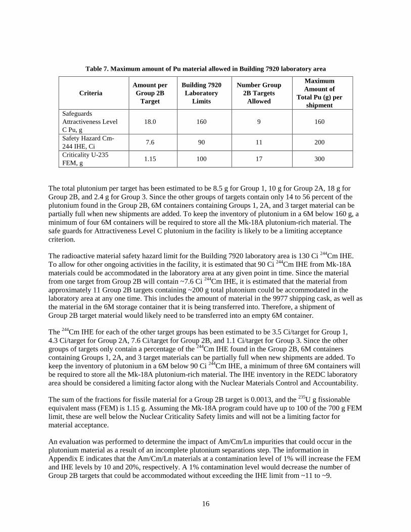
Table 7. Maximum amount of Pu material allowed in Building 7920 laboratory area
Criteria Amount per Group 2B
Target
Building 7920 Laboratory
Limits
Number Group 2B Targets
Allowed
Maximum Amount of
Total Pu (g) per shipment
Safeguards Attractiveness Level C Pu, g
18.0 160 9 160
Safety Hazard Cm-244 IHE, Ci 7.6 90 11 200
Criticality U-235 FEM, g 1.15 100 17 300
The total plutonium per target has been estimated to be 8.5 g for Group 1, 10 g for Group 2A, 18 g for Group 2B, and 2.4 g for Group 3. Since the other groups of targets contain only 14 to 56 percent of the plutonium found in the Group 2B, 6M containers containing Groups 1, 2A, and 3 target material can be partially full when new shipments are added. To keep the inventory of plutonium in a 6M below 160 g, a minimum of four 6M containers will be required to store all the Mk-18A plutonium-rich material. The safe guards for Attractiveness Level C plutonium in the facility is likely to be a limiting acceptance criterion.
The radioactive material safety hazard limit for the Building 7920 laboratory area is 130 Ci 244Cm IHE. To allow for other ongoing activities in the facility, it is estimated that 90 Ci 244Cm IHE from Mk-18A materials could be accommodated in the laboratory area at any given point in time. Since the material from one target from Group 2B will contain ~7.6 Ci 244Cm IHE, it is estimated that the material from approximately 11 Group 2B targets containing ~200 g total plutonium could be accommodated in the laboratory area at any one time. This includes the amount of material in the 9977 shipping cask, as well as the material in the 6M storage container that it is being transferred into. Therefore, a shipment of Group 2B target material would likely need to be transferred into an empty 6M container.
The 244Cm IHE for each of the other target groups has been estimated to be 3.5 Ci/target for Group 1, 4.3 Ci/target for Group 2A, 7.6 Ci/target for Group 2B, and 1.1 Ci/target for Group 3. Since the other groups of targets only contain a percentage of the 244Cm IHE found in the Group 2B, 6M containers containing Groups 1, 2A, and 3 target materials can be partially full when new shipments are added. To keep the inventory of plutonium in a 6M below 90 Ci 244Cm IHE, a minimum of three 6M containers will be required to store all the Mk-18A plutonium-rich material. The IHE inventory in the REDC laboratory area should be considered a limiting factor along with the Nuclear Materials Control and Accountability.
The sum of the fractions for fissile material for a Group 2B target is 0.0013, and the 235U g fissionable equivalent mass (FEM) is 1.15 g. Assuming the Mk-18A program could have up to 100 of the 700 g FEM limit, these are well below the Nuclear Criticality Safety limits and will not be a limiting factor for material acceptance.
An evaluation was performed to determine the impact of Am/Cm/Ln impurities that could occur in the plutonium material as a result of an incomplete plutonium separations step. The information in Appendix E indicates that the Am/Cm/Ln materials at a contamination level of 1% will increase the FEM and IHE levels by 10 and 20%, respectively. A 1% contamination level would decrease the number of Group 2B targets that could be accommodated without exceeding the IHE limit from ~11 to ~9.
17
Curium-244 is the only significant contributor. A 0.2% contamination level would decrease the number of targets that could be in the Building 7920 laboratory area at one time by only 4%, having essentially no impact on the number of targets that could be shipped. Purification of plutonium from mixed oxides by anion exchange has shown that 0.04 to 0.2% of the other isotopes could be expected to be in the plutonium product (Kyser and King 2012). Therefore, contaminants in the plutonium-rich material should not be a limiting factor for accepting the material at ORNL, but the Am/Cm/Ln contamination level in the plutonium-rich material will need to be determined prior to packaging and shipment.
3.2.2.2 Building 7930 Cell F Storage Requirements
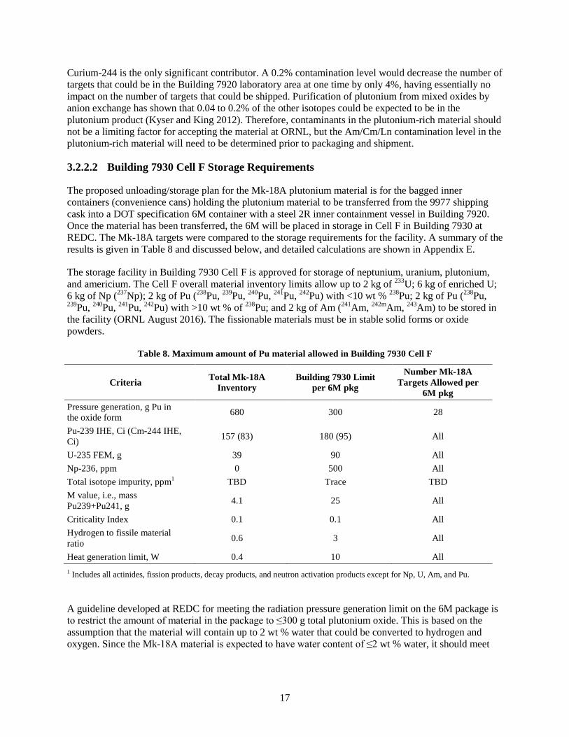
The proposed unloading/storage plan for the Mk-18A plutonium material is for the bagged inner containers (convenience cans) holding the plutonium material to be transferred from the 9977 shipping cask into a DOT specification 6M container with a steel 2R inner containment vessel in Building 7920. Once the material has been transferred, the 6M will be placed in storage in Cell F in Building 7930 at REDC. The Mk-18A targets were compared to the storage requirements for the facility. A summary of the results is given in Table 8 and discussed below, and detailed calculations are shown in Appendix E.
The storage facility in Building 7930 Cell F is approved for storage of neptunium, uranium, plutonium, and americium. The Cell F overall material inventory limits allow up to 2 kg of 233U; 6 kg of enriched U; 6 kg of Np (237Np); 2 kg of Pu (238Pu, 239Pu, 240Pu, 241Pu, 242Pu) with <10 wt % 238Pu; 2 kg of Pu (238Pu, 239Pu, 240Pu, 241Pu, 242Pu) with >10 wt % of 238Pu; and 2 kg of Am (241Am, 242mAm, 243Am) to be stored in the facility (ORNL August 2016). The fissionable materials must be in stable solid forms or oxide powders.
Table 8. Maximum amount of Pu material allowed in Building 7930 Cell F
Criteria Total Mk-18A Inventory
Building 7930 Limit per 6M pkg
Number Mk-18A Targets Allowed per
6M pkg Pressure generation, g Pu in the oxide form 680 300 28
Pu-239 IHE, Ci (Cm-244 IHE, Ci) 157 (83) 180 (95) All
U-235 FEM, g 39 90 All Np-236, ppm 0 500 All Total isotope impurity, ppm1 TBD Trace TBD M value, i.e., mass Pu239+Pu241, g 4.1 25 All
Criticality Index 0.1 0.1 All Hydrogen to fissile material ratio 0.6 3 All
Heat generation limit, W 0.4 10 All 1 Includes all actinides, fission products, decay products, and neutron activation products except for Np, U, Am, and Pu.
A guideline developed at REDC for meeting the radiation pressure generation limit on the 6M package is to restrict the amount of material in the package to ≤300 g total plutonium oxide. This is based on the assumption that the material will contain up to 2 wt % water that could be converted to hydrogen and oxygen. Since the Mk-18A material is expected to have water content of ≤2 wt % water, it should meet
18
this criterion. Since the Building 7930 unloading/repackaging criteria will limit the total plutonium per container to 160 Ci, this guideline will not be a limiting factor for acceptance of the material.
As shown in Table 8, the plutonium-rich material is expected to easily meet the Cell F storage criteria for 239Pu IHE, 235U FEM, the M value (mass of 239Pu plus 241Pu), criticality index, hydrogen to fissile material ratio, and head generation. All the targets could be processed and shipped at one time, and they would be well below these Cell F storage criteria.
Any 236Np will be limited to trace quantities, i.e., ≤500 ppm by weight. The Mk-18A material should not contain 236Np, so this criterion should not be an issue.
Cell F is approved for storage of Np, U, Am, and Pu. Therefore, they are included in the 239Pu IHE inventory in Table 8. All other radioisotopes are limited by the total impurities being present in “trace quantities.” The term “trace quantity” is not defined in the SAR, but a guideline that is being used for all other actinides, fission products, decay products, and neutron activation products is for their total and should be limited to ≤100 ppm. Purification of plutonium from mixed oxides by anion exchange has shown that impurity levels on the order of <0.01% can be expected for many isotopes, but values of up to 0.2 % are not uncommon (Kyser and King 2012). Therefore, it may be technically difficult to achieve these limits. This is an area that will need to be addressed in more detail as part of the MTMRP development efforts, and the definition of “trace quantity” needs to be clarified in a future revision of the Building 7930 SAR.
The inner container, or convenience can, may consist of a single sealed metal container or multiple nested containers, at least one of which must be a sealed metal container. The maximum size of the inner shipping container that can fit into a 2R is 4.25 in. OD by 14 in. high, twice the height of a standard ORNL isotope storage can. In addition, 25% free volume in the 2R must be maintained. One way to assure this is to reduce the maximum height of the convenience can or material loaded into the container to 10.5 in. Another option is to ship smaller convenience cans such that the void volume requirement can be met by ORNL during transfer into the 2R. In addition, plastics are not allowed to be in contact with the fissionable material in storage containers in Cell F.
3.2.2.3 Impact of Contaminants on Pu Oxide Material
The inner containers containing the plutonium material will be stored in 6M packages with steel 2R inner containment vessels. It is estimated that all of the plutonium product could fit into one ORNL isotope storage can filled to 70%. This assumes the plutonium product is 100% pure, but it indicates that volume should not be a limiting factor.
Inert material in the Mk-18A plutonium product stream is not likely to be an issue because inert materials should not be present in the product from the ion exchange step used to separate the plutonium from the Am/Cm/Ln stream.
It is assumed that the plutonium material recovered from Mk-18A targets will be enriched at some point in the future to meet the needs of end users and is most likely to be performed by electromagnetic isotope separation (EMIS). An initial step in the EMIS process is to dissolve the oxide powder. The MTMRP product should be converted to an oxide at a low temperature (650 to 750 °C) so that the material will not be extremely difficult to dissolve in the future.
EMIS technology is based on a mass separation. Therefore, any element having isotopes with the same mass of 244Pu, such as 244Cm, would negatively impact the efficiency of the EMIS enrichment process. In addition, other radioisotopes in the plutonium material could impact whether steps in the EMIS process
19
could be carried out in glove boxes and a low radiological hazard category facility. Therefore, purified PuO2 is the preferred feed for enrichment to avoid potential constraints for future processing of the material. Purification of plutonium from mixed oxides by anion exchange has shown that impurity levels on the order of <0.01% can be expected for many isotopes, but values of up to 0.2% are not uncommon (Kyser and King 2012). Therefore, it may be technically difficult to achieve very low contaminant levels that may be desired for a future EMIS facility. This is an area that should be addressed in more detail as part of the MTMRP development efforts.
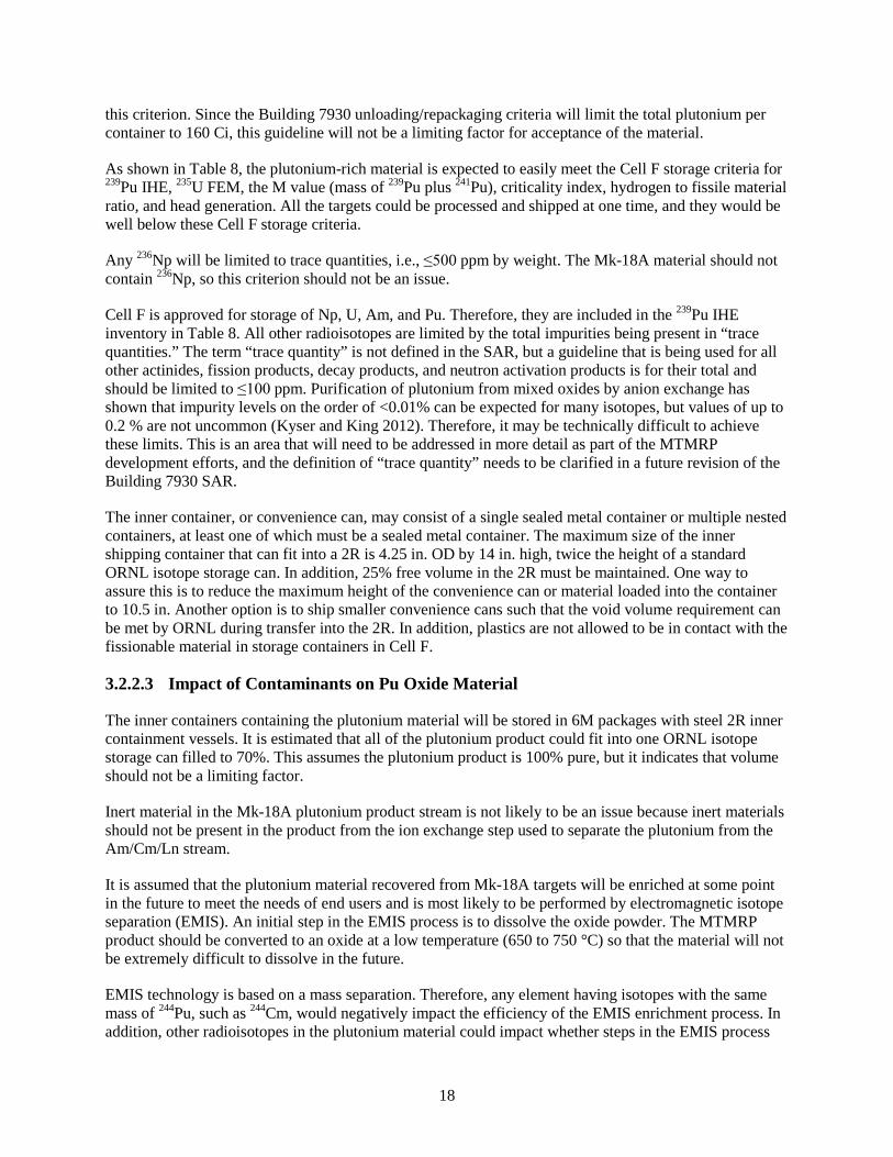
3.2.2.4 Factors Controlling Am/Cm/Ln Material Acceptance Criteria
The results of the evaluations performed in Sections 3.2.2.1 through 3.2.2.4 are summarized in Table 9. Assuming the SARP for the 9977 cask is modified to accommodate the Mk-18A contents so that it will no longer be a limiting factor, the inventory limits for the Building 7920 laboratory area where the cask will be unloaded will define the acceptance criteria for the amount of plutonium that can be put in one shipment from SRNL to ORNL. The storage requirements in Building 7930 Cell F will limit the amount of each isotope other than plutonium that can be present in the plutonium-rich material.
Table 9. Transportation, unloading, and storage factors impacting plutonium-rich material shipments1,2
Factor Impacting Acceptance Criteria
Unloading in Building 79203 Storage in Building 7930 Future Processing
Requirements Total Pu (g) 160 264 Cm-244 IHE (Ci) 90 95 U-235 FEM (g) 100 90 Np-236 (ppm) 500
Total isotope impurity, ppm 1004 As low as practice to reduce shielding and
safety design requirements Hydrogen to fissile material ratio 3
Water Content (wt%) ≤2 Void Volume5 (vol%) ≥25 Drying Temperature (°C) ≤750 1Values highlighted in yellow indicate limiting conditions for each criterion. 2Assuming the SARP and certificate of compliance for the 9977 cask will be approved for a new content envelop that exceeds the acceptance criteria established for unloading/storage at ORNL. 3Assuming the plutonium stream contains less than 0.2% of the Am/Cm/Ln material. 4 Includes all actinides, fission products, decay products, and neutron activation products except for Np, U, Am, and Pu. 5Building 7930 2R storage container requires 25% voids. Requirement can be met by SRNL when filling convenience cans or by ORNL during repackaging
21
4. PRELIMINARY TRANSPORT AND ACCEPTANCE CRITERIA
4.1 CRITERIA FOR AM/CM/LN MATERIAL
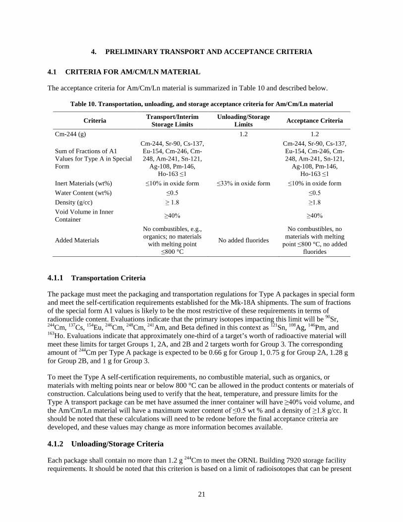
The acceptance criteria for Am/Cm/Ln material is summarized in Table 10 and described below.
Table 10. Transportation, unloading, and storage acceptance criteria for Am/Cm/Ln material
Criteria Transport/Interim Storage Limits
Unloading/Storage Limits Acceptance Criteria
Cm-244 (g) 1.2 1.2
Sum of Fractions of A1 Values for Type A in Special Form
Inert Materials (wt%) ≤10% in oxide form ≤33% in oxide form ≤10% in oxide form Water Content (wt%) ≤0.5 ≤0.5
Density (g/cc) ≥ 1.8 ≥1.8 Void Volume in Inner Container ≥40% ≥40%
Added Materials
No combustibles, e.g., organics; no materials
with melting point ≤800 °C
No added fluorides
No combustibles, no materials with melting
point ≤800 °C, no added fluorides
4.1.1 Transportation Criteria
The package must meet the packaging and transportation regulations for Type A packages in special form and meet the self-certification requirements established for the Mk-18A shipments. The sum of fractions of the special form A1 values is likely to be the most restrictive of these requirements in terms of radionuclide content. Evaluations indicate that the primary isotopes impacting this limit will be 90Sr, 244Cm, 137Cs, 154Eu, 246Cm, 248Cm, 241Am, and Beta defined in this context as 121Sn, 108Ag, 146Pm, and 163Ho. Evaluations indicate that approximately one-third of a target’s worth of radioactive material will meet these limits for target Groups 1, 2A, and 2B and 2 targets worth for Group 3. The corresponding amount of 244Cm per Type A package is expected to be 0.66 g for Group 1, 0.75 g for Group 2A, 1.28 g for Group 2B, and 1 g for Group 3.
To meet the Type A self-certification requirements, no combustible material, such as organics, or materials with melting points near or below 800 °C can be allowed in the product contents or materials of construction. Calculations being used to verify that the heat, temperature, and pressure limits for the Type A transport package can be met have assumed the inner container will have ≥40% void volume, and the Am/Cm/Ln material will have a maximum water content of ≤0.5 wt % and a density of ≥1.8 g/cc. It should be noted that these calculations will need to be redone before the final acceptance criteria are developed, and these values may change as more information becomes available.
4.1.2 Unloading/Storage Criteria
Each package shall contain no more than 1.2 g 244Cm to meet the ORNL Building 7920 storage facility requirements. It should be noted that this criterion is based on a limit of radioisotopes that can be present
22
in the ORNL unloading/storage facility and is derived from an estimate of the amount of material that could likely be in the facility from other projects at any given time. The composition of each Mk-18A shipment must be approved by the appropriate ORNL personnel prior to transport from SRNL to ensure adequate inventory space in the receiving facility.
The material will be shipped as an oxide powder containing no more than 10 wt % aluminum silicates in oxide form. Stable rare earth isotopes are not included in this inert material guideline. Inert materials in the Am/Cm/Ln product should be minimized as much as practical below these limits to avoid unnecessary increases in the number of shipments and containers requiring storage at ORNL. Reduction in the amount of inert materials and stable rare earths would also make it easier to meet the Type A in special form transportation limits described above.
No added fluorides will be accepted in the Am/Cm/Ln materials.
SRNL shall perform characterization of the product in each Type A package to meet transportation requirements and ORNL acceptance criteria and place a tamper indicating device on each shipping container. ORNL will accept the SRNL characterization as long as the tamper indicating device is intact upon receipt and it meets a characterization plan that has been concurred by ORNL to ensure adequate characterization has been done to meet the acceptance criteria.
4.2 CRITERIA FOR PLUTONIUM RICH MATERIAL
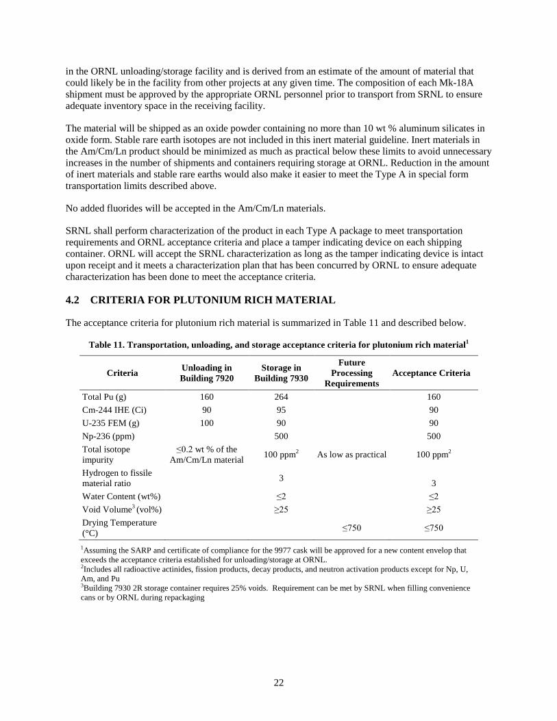
The acceptance criteria for plutonium rich material is summarized in Table 11 and described below.
Table 11. Transportation, unloading, and storage acceptance criteria for plutonium rich material1
Criteria Unloading in Building 7920
Storage in Building 7930
Future Processing
Requirements Acceptance Criteria
Total Pu (g) 160 264 160 Cm-244 IHE (Ci) 90 95 90 U-235 FEM (g) 100 90 90 Np-236 (ppm) 500 500 Total isotope impurity
≤0.2 wt % of the Am/Cm/Ln material 100 ppm2 As low as practical 100 ppm2
Hydrogen to fissile material ratio 3
3 Water Content (wt%) ≤2 ≤2 Void Volume3 (vol%) ≥25 ≥25 Drying Temperature (°C) ≤750 ≤750
1Assuming the SARP and certificate of compliance for the 9977 cask will be approved for a new content envelop that exceeds the acceptance criteria established for unloading/storage at ORNL. 2Includes all radioactive actinides, fission products, decay products, and neutron activation products except for Np, U, Am, and Pu 3Building 7930 2R storage container requires 25% voids. Requirement can be met by SRNL when filling convenience cans or by ORNL during repackaging
23
4.2.1 Transportation Criteria
The package must meet the packaging and transportation regulations for the Model 9977 Type B transport cask. It is assumed that the present SARP and certificate of compliance will be modified for the Mk-18A contents so that transportation requirements will not be limiting factors for acceptance of the Mk-18A plutonium shipments as discussed in Section 3.2.2.1.
4.2.2 Unloading/Storage Criteria
The inner container, or convenience can, may consist of a single sealed metal container or multiple nested containers, at least one of which must be a sealed metal container. The maximum size of the inner shipping container allowed is 4.25 in. OD by 14 in. high. In addition, 25% free volume must be maintained in the ORNL storage container. Plastics are not allowed to be in contact with the fissionable material in ORNL storage containers. SRNL facility requirements presently do not allow the use of sealed containers, and they use plastic bags for contamination control. If the inner containers received from SRNL do not meet the ORNL storage criteria for plastics and/or sealed containers, the inner containers from SRNL will be repackaged at ORNL in a glove box prior to being loaded into the ORNL storage container. SRNL shipping containers should be designed to minimize repackaging at ORNL to the extent practical.
The contents must be an oxide powder with a maximum water content of ≤2 wt %.
Each package shall contain no more than 160 g total plutonium, 90 Ci 244Cm IHE, 90 g 235U FEM, and ≤500 ppm 236Np. All other radioactive actinides, fission products, decay products, and neutron activation products in a convenience container will in total be ≤100 ppm. It should be noted that several of these criteria are based on limits of radioisotopes that can be present in the ORNL facilities and are derived from estimates of the amount of material that could likely be in the facilities from other projects at any given time. The composition of each Mk-18A shipment must be approved by the appropriate ORNL personnel prior to transport from SRNL to ensure that adequate inventory space is available in the ORNL receiving facility.
SRNL shall perform characterization of the product in each Type B package to meet transportation requirements and ORNL acceptance criteria and, a tamper indicating device will be placed on each shipping container. ORNL will accept the SRNL characterization as long as the tamper indicating device is intact upon receipt and it meets a characterization plan that has been concurred by ORNL to ensure adequate characterization has been done to meet the acceptance criteria.
4.2.3 Future Processing Requirements
It is assumed that the plutonium material recovered from Mk-18A targets will be enriched in the future to meet the needs of end users and that the separation is most likely to be performed by EMIS technology. An initial step in the EMIS process is to dissolve the oxide powder. The MTMRP product should be converted to an oxide at a low temperature (650–750 °C) so that the material will not be extremely difficult to dissolve in the future. A purified PuO2 is the preferred feed for enrichment to avoid potential problems for future processing of the material. Any element having isotopes with the same mass of 244Pu, such as 244Cm, would negatively impact the efficiency of the EMIS enrichment process. In addition, other radioisotopes in the plutonium material could impact whether steps in the EMIS process could be carried out in glove boxes and in a low radiological hazard category facility. Therefore, impurities in the plutonium stream should be minimized as much as is practical.
25
5. SUMMARY AND CONCLUSIONS
This document establishes initial preliminary acceptance criteria based on calculations performed using the present proposed concepts for (1) processing conditions of targets at SRNL, (2) shipping containers for transport of materials between SRNL and ORNL, (3) staging/storage locations at ORNL, and (4) future material processing operations to be performed at ORNL. The acceptance criteria provide information to support planning of processing, packaging, and shipping of the Mk-18A. They are the results of the evaluations based on preliminary information. These evaluations should be updated when the details of the treatment processes, transportation, interim staging, and storage concepts are further developed, and the acceptance criteria may need to be updated accordingly.
For the Am/Cm/Ln material, the radionuclide content of transport/storage packages is likely to be limited by the Type A special form content requirements which indicate that approximately one-third of a target’s worth of radioactive material will meet these limits for target Groups 1, 2A, and 2B and 2 targets worth for Group 3. The corresponding amount of 244Cm per Type A package is expected to be 0.66 g for Group 1, 0.75 g for Group 2A, 1.28 g for Group 2B, and 1 g for Group 3. Inert material in the Am/Cm/Ln product will increase the volume of material above the amount needed to meet Type A special form transportation requirements, thereby increasing the number of packages that must be packaged, shipped, and stored. Inert materials in the Am/Cm/Ln product should be minimized as much as practical to avoid unnecessary increases in the number of shipments and containers requiring storage at ORNL.
For the plutonium material, the radionuclide content of the packages is likely to be limited by the unloading and storage requirements at ORNL facilities. Each shipping package will be limited to 160 g total plutonium, 90 Ci 244Cm IHE, 90 g 235U FEM, and 500 ppm 236Np. All other radioactive actinides, fission products, decay products, and neutron activation products in a convenience container will total ≤100 ppm. This criterion may be very challenging to meet technically and is an area that will need to be addressed in more detail as part of the MTMRP development efforts.
These ORNL unloading and storage requirements will be the controlling acceptance criteria for the plutonium rich material assuming the content envelop for the Model 9977 Type B shipping container is modified to be less restrictive than these criteria.
This document will need to be updated to reflect new information as new details on the treatment processes, transportation packages, interim staging, and storage concepts are developed. Future action items needed to finalize the Mk-18A acceptance criteria include:
• Refine estimates of the water content of the plutonium and Am/Cm/Ln materials.
• Refine estimates of the density of the plutonium and Am/Cm/Ln materials.
• Refine estimates of impurities in the product materials, both radioisotopes and inert material.
• Finalize the design of the Type A package for Am/Cm/Ln material.
• Recalculate radiological dose, heat, pressure, and temperature for the final Type A container.
• Certify the SFC.
• Develop the new contents envelop for the Model 9977 Type B container.
26
• Obtain approval from regulators on the proposed changes to the content envelop for the Model 9977 Type B container.
• Refine the acceptance criteria for the limiting factors for unloading and storage of the plutonium-rich material.
• Revise the Building 7930 SAR to clarify impurity limits for storage in Cell F.
• Develop a characterization plan to ensure that the acceptance criteria are met.
• Revise the acceptance criteria document to incorporate this additional information.
27
6. REFERENCES
W. Bickford, Estimation of Fission Products in the Mark-18A OH Targets, OBU-OPD-2003-0043, Savannah River Company, September 16, 2003.
S. Branney, C. Verst, N. Bridges, Mark-18A Target Irradiation Model and Non-Destructive Analysis, SNRL-TR-2015-00316, Revision 0, Savannah River National Laboratory, December 2015.
D. Foster, Radiochemical Engineering Development Center (REDC) Building 7930 – Cell F Packaged Nuclear Material Storage Operations – Pressure Capacity of the Los Alamos National Laboratory (LANL) Special Form Capsule (SFC) Model II, ORNL/7930/DAC/04-05, UT-Battelle, LLC, Oak Ridge National Laboratory, June 2004.
E. Kyser and W. King, HB-Line Anion Exchange Purification of AFS-2 Plutonium for MOX, SRNL-STI-2012-00233, Revision 0, Savannah River National Laboratory, April 2012.
D. Martinez, et al., Development and Certification of a Special Form Capsule (Model III) for Sealed Sources to Facilitate Transportation and Storage as Special Form Material, http://osrp.lanl.gov.
U.S. Department of Energy, Hazard Categorization and Accident Analysis Techniques for Compliance with DOE Order 5480.23, Nuclear Safety Analysis Reports, DOE-STD-1027-92, September 1997.
U.S. Department of Energy, Stabilization, Packaging, and Storage of Plutonium-Bearing Materials, DOE-STD-3013-2004, April 2004, pg. 26.
U.S. Department of Energy, Revision 12 to DOE CoC USA/9977/B(M)F-96, July 2012.
S. Robinson, D. Benker, B. Patton, Clarice Phelps, Mark-18A (Mk-18A) Target Processing at Oak Ridge National Laboratory, ORNL/TM-2015/577R1, UT-Battelle, LLC, Oak Ridge National Laboratory, May 2016.
Savannah River National Laboratory, Safety Analysis Report for Packaging Model 9977 Addendum 5 Justification for Training Sources Contents, S-SARA-G-00009, Revision 2, May 2010.
Oak Ridge National Laboratory, Safety Analysis Report, Radiochemical Engineering Development Center, Building 7920, ORNL/7920/SAR Revision 8, UT-Battelle, LLC, January 2016.
Oak Ridge National Laboratory, Safety Analysis Report, Radiochemical Engineering Development Center, Building 7930, ORNL/7930/SAR Revision 8, UT-Battelle, LLC, August 2016.
Group 1 (6 targets) Group 2A (21 targets) Group 3 (21 Targets) All Groups (65 Targets)
B-1
APPENDIX B. MK-18A TYPE A PACKAGE EVALUATION – DOSE CALCULATIONS
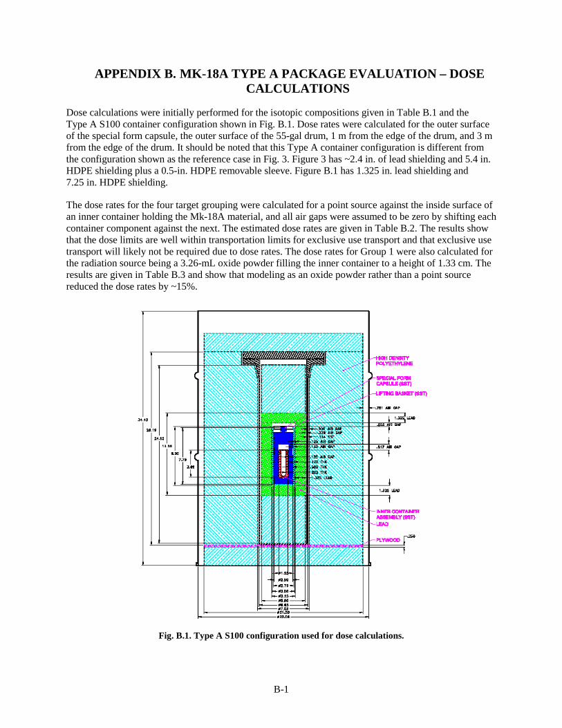
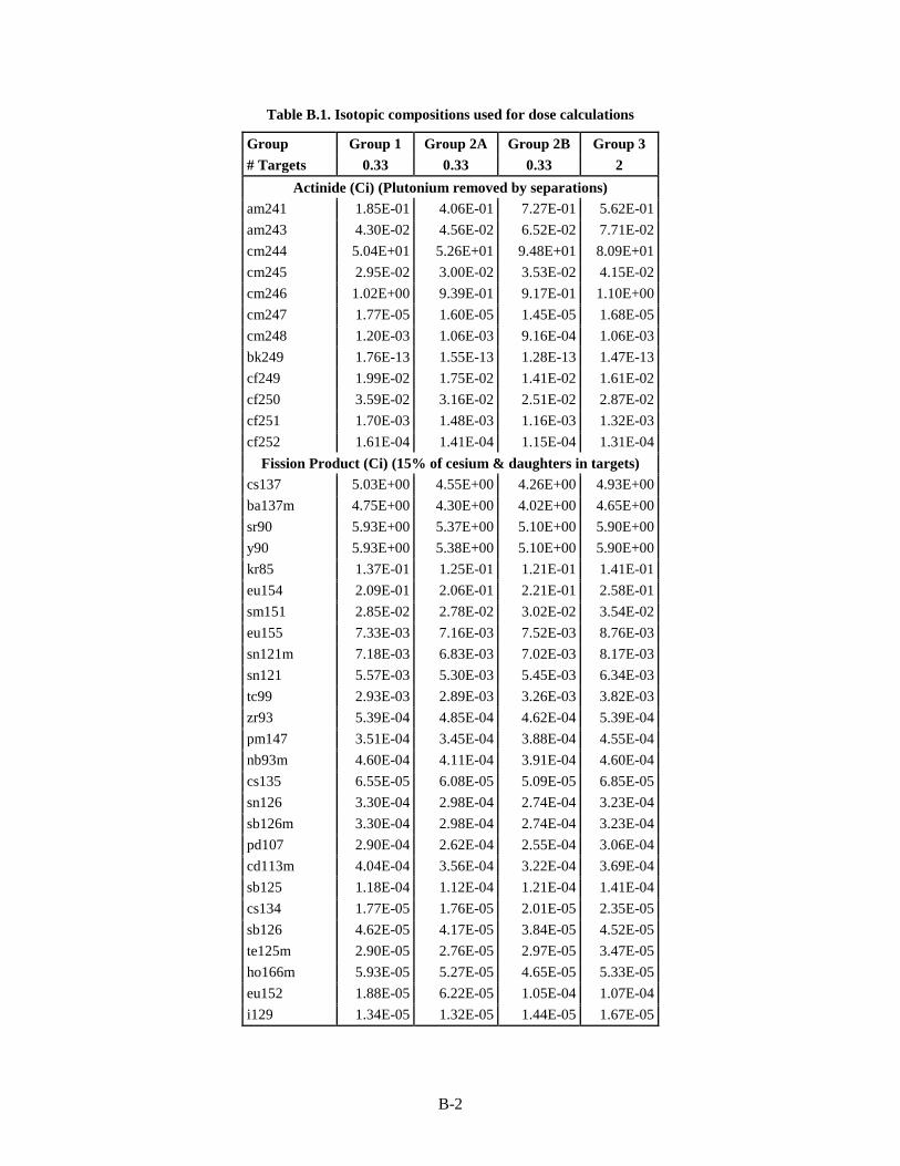
Dose calculations were initially performed for the isotopic compositions given in Table B.1 and the Type A S100 container configuration shown in Fig. B.1. Dose rates were calculated for the outer surface of the special form capsule, the outer surface of the 55-gal drum, 1 m from the edge of the drum, and 3 m from the edge of the drum. It should be noted that this Type A container configuration is different from the configuration shown as the reference case in Fig. 3. Figure 3 has ~2.4 in. of lead shielding and 5.4 in. HDPE shielding plus a 0.5-in. HDPE removable sleeve. Figure B.1 has 1.325 in. lead shielding and 7.25 in. HDPE shielding.
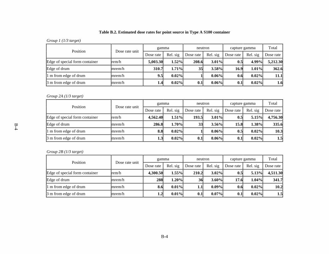
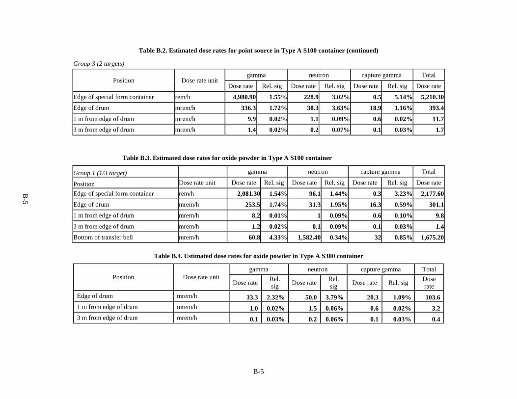
The dose rates for the four target grouping were calculated for a point source against the inside surface of an inner container holding the Mk-18A material, and all air gaps were assumed to be zero by shifting each container component against the next. The estimated dose rates are given in Table B.2. The results show that the dose limits are well within transportation limits for exclusive use transport and that exclusive use transport will likely not be required due to dose rates. The dose rates for Group 1 were also calculated for the radiation source being a 3.26-mL oxide powder filling the inner container to a height of 1.33 cm. The results are given in Table B.3 and show that modeling as an oxide powder rather than a point source reduced the dose rates by ~15%.
Fig. B.1. Type A S100 configuration used for dose calculations.
B-2
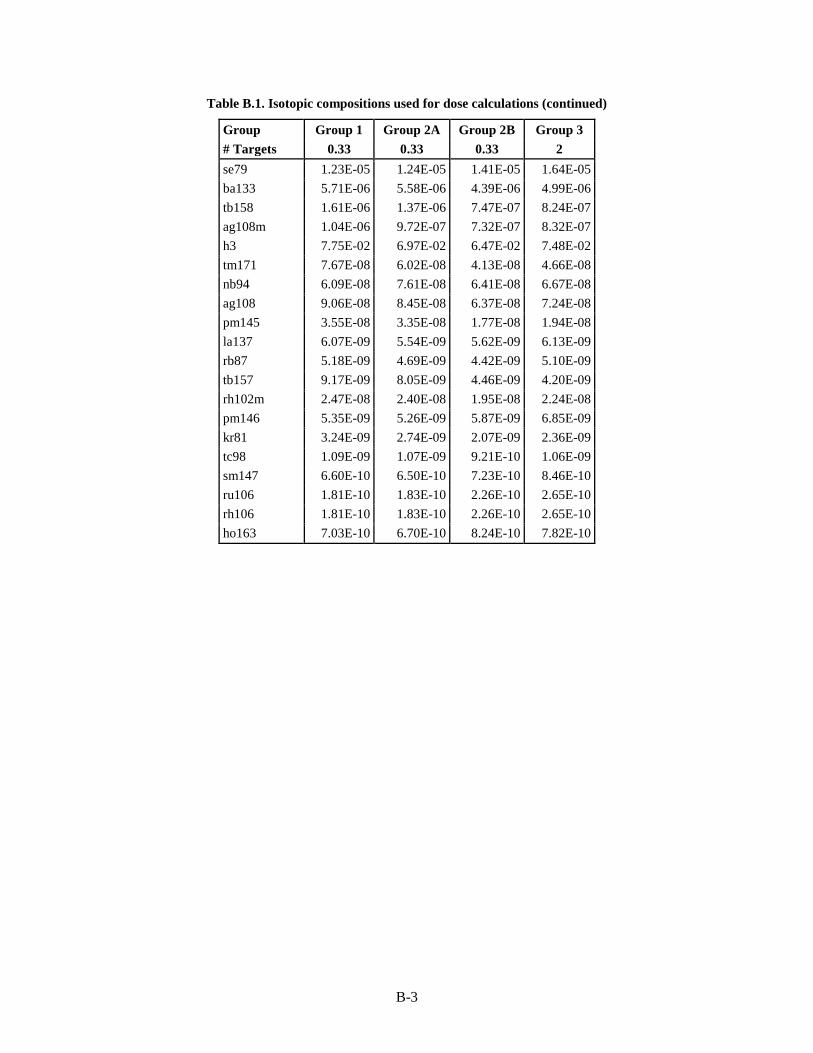
Table B.1. Isotopic compositions used for dose calculations
Group Group 1 Group 2A Group 2B Group 3 # Targets 0.33 0.33 0.33 2
Table B.2. Estimated dose rates for point source in Type A S100 container
Group 1 (1/3 target)
Position Dose rate unit gamma neutron capture gamma Total
Dose rate Rel. sig Dose rate Rel. sig Dose rate Rel. sig Dose rate
Edge of special form container rem/h 5,003.30 1.52% 208.6 3.01% 0.5 4.99% 5,212.30 Edge of drum mrem/h 310.7 1.71% 35 3.58% 16.9 1.01% 362.6
1 m from edge of drum mrem/h 9.5 0.02% 1 0.06% 0.6 0.02% 11.1 3 m from edge of drum mrem/h 1.4 0.02% 0.1 0.06% 0.1 0.02% 1.6
Group 2A (1/3 target)
Position Dose rate unit gamma neutron capture gamma Total
Dose rate Rel. sig Dose rate Rel. sig Dose rate Rel. sig Dose rate
Edge of special form container rem/h 4,562.40 1.51% 193.5 3.01% 0.5 5.15% 4,756.30
Edge of drum mrem/h 286.8 1.70% 33 3.56% 15.8 1.38% 335.6 1 m from edge of drum mrem/h 8.8 0.02% 1 0.06% 0.5 0.02% 10.3
3 m from edge of drum mrem/h 1.3 0.02% 0.1 0.06% 0.1 0.02% 1.5
Group 2B (1/3 target)
Position Dose rate unit
gamma neutron capture gamma Total
Dose rate Rel. sig Dose rate Rel. sig Dose rate Rel. sig Dose rate
Edge of special form container rem/h 4,300.50 1.55% 210.2 3.02% 0.5 5.13% 4,511.30 Edge of drum mrem/h 288 1.20% 36 3.60% 17.6 1.04% 341.7
1 m from edge of drum mrem/h 8.6 0.01% 1.1 0.09% 0.6 0.02% 10.2
3 m from edge of drum mrem/h 1.2 0.01% 0.1 0.07% 0.1 0.02% 1.5
B-5
B-5
Table B.2. Estimated dose rates for point source in Type A S100 container (continued)
Group 3 (2 targets)
Position Dose rate unit gamma neutron capture gamma Total
Dose rate Rel. sig Dose rate Rel. sig Dose rate Rel. sig Dose rate
Edge of special form container rem/h 4,980.90 1.55% 228.9 3.02% 0.5 5.14% 5,210.30 Edge of drum mrem/h 336.3 1.72% 38.3 3.63% 18.9 1.16% 393.4
1 m from edge of drum mrem/h 9.9 0.02% 1.1 0.09% 0.6 0.02% 11.7 3 m from edge of drum mrem/h 1.4 0.02% 0.2 0.07% 0.1 0.03% 1.7
Table B.3. Estimated dose rates for oxide powder in Type A S100 container
Group 1 (1/3 target) gamma neutron capture gamma Total
Position Dose rate unit Dose rate Rel. sig Dose rate Rel. sig Dose rate Rel. sig Dose rate
Edge of special form container rem/h 2,081.30 1.54% 96.1 1.44% 0.3 3.23% 2,177.60 Edge of drum mrem/h 253.5 1.74% 31.3 1.95% 16.3 0.59% 301.1
1 m from edge of drum mrem/h 8.2 0.01% 1 0.09% 0.6 0.10% 9.8
3 m from edge of drum mrem/h 1.2 0.02% 0.1 0.09% 0.1 0.03% 1.4 Bottom of transfer bell mrem/h 60.8 4.33% 1,582.40 0.34% 32 0.85% 1,675.20
Table B.4. Estimated dose rates for oxide powder in Type A S300 container
Position Dose rate unit gamma neutron capture gamma Total
Dose rate Rel. sig Dose rate Rel.
sig Dose rate Rel. sig Dose rate
Edge of drum mrem/h 33.3 2.32% 50.0 3.79% 20.3 1.09% 103.6 1 m from edge of drum mrem/h 1.0 0.02% 1.5 0.06% 0.6 0.02% 3.2 3 m from edge of drum mrem/h 0.1 0.03% 0.2 0.06% 0.1 0.03% 0.4
B-6
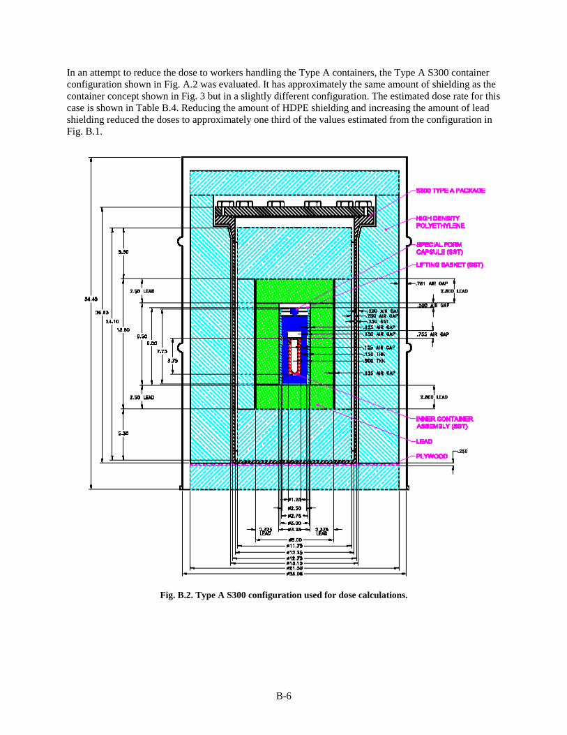
In an attempt to reduce the dose to workers handling the Type A containers, the Type A S300 container configuration shown in Fig. A.2 was evaluated. It has approximately the same amount of shielding as the container concept shown in Fig. 3 but in a slightly different configuration. The estimated dose rate for this case is shown in Table B.4. Reducing the amount of HDPE shielding and increasing the amount of lead shielding reduced the doses to approximately one third of the values estimated from the configuration in Fig. B.1.
Fig. B.2. Type A S300 configuration used for dose calculations.
C-1
APPENDIX C. MK-18A TYPE A PACKAGE EVALUATION - TEMPERATURE AND PRESSURE CALCULATIONS
Thermal Hydraulic and Irradiation Engineering Reactor and Nuclear Systems Division
Oak Ridge National Laboratory March 2015
C-2
1. Purpose, Calculation Methodology, and Assumptions 1. The purpose of this calculation is to estimate the maximum pressure and temperature inside a
“Modified Model II-2 Special Form Capsule” containing a Curium/lanthanide fission product oxide inside a “Convenience Can”
2. The maximum allowable pressure for the “Capsule” is 219 psig (233.7 psia), value taken from Ref. 1 (Sheet 3 of 3, Section 4. Conclusions). There are four pressure limits in Ref. 1: 219 psig, 328 psig, 504 psig and 2268 psig – the lowest, most conservative value has been selected. Reference 2, page 5, states another pressure limit of 318 psi – the previous value of 219 psig has been kept for conservatism.
3. The Curium/lanthanide fission product oxide to be loaded inside the “Convenience Can” consists of a quarter of a target with a mass of oxide material of 21.5 g, a volume of 12 cm3, with 0.5% weight water content, and a density of 1.8 g/cm3 (values from Ref. 3).
4. There are three different compositions of this product oxide (three different groups) – their heat loads are calculated in Section 2.
5. The “Special Form Capsule” is located inside a “S100 Type A Pipe Container” which is located inside a “S100 Type A 55 gal” drum together with different lead and polyethylene shields and with dimensions described in Section 3 and shown in Fig. 1 (from Ref. 4).
6. The empty spaces (gaps between containers and shields) and inside the Capsule and the Can are filled with air.
7. It is assumed that if the pressure inside the “Convenience Can” is higher than the pressure inside the “Special Form Capsule”, the “Convenience Can” will leak into the “Special Form Capsule” and both pressures will equalize.
8. For pressure calculations, the free volumes inside the “Convenience Can” and inside the “Special Form Capsule” will be added and considered as a single volume.
9. The total amount of water in the product oxide will decompose by radiolysis into hydrogen and oxygen gases that will contribute to the total pressure inside the “Special Form Capsule.” Also, the helium gas generation from α-decay was assumed to be negligible.
10. The total pressure, PT, inside the “Special Form Capsule” is the summation of two components, one from heating the fill gas (air), named Pa, and the other component from the hydrogen and oxygen generated from the water by radiolysis, named P2: PT = Pa + P2 [1]
11. The initial temperature of all the components in the package is assumed to be To = 20°C (68°F) 12. The initial pressure inside all the components is assumed to be atmospheric Po = 1 atm (101 kPa
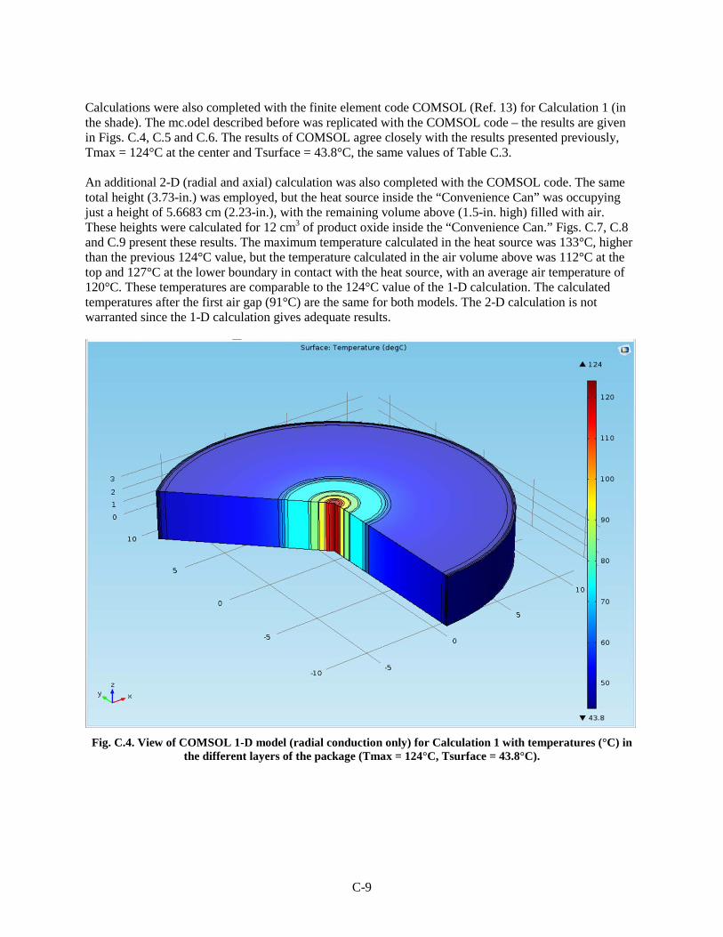
or 14.7 psia) 13. The fill gas pressure component (Pa) will be calculated assuming the gas is ideal, as a product of
the initial pressure (Po) and the ratio of the final (Tf) to the initial absolute temperatures (To): Pa = Po (Tf/To) [2]
14. The second pressure component due to the hydrogen/oxygen generation will be calculated as follows (per Appendix B of Ref. 5):
a) calculate moles of hydrogen (GH) and oxygen (GO) generated from the water: GT = GH + GO = mf/18 + 0.5mf/18 = 1.5mf/18 [3] with, m = total mass of material (g), and f = fraction of water (no units) b) calculate the total volume ,VT, occupied by these moles, GT, with 1 mole = 22.4 L at 1 atm (14.7 psia) and 0°C (273 K): VT = 22.4 GT [4]
C-3
c) calculate the free volume, Vfree, (in L) inside the “Special Form Capsule” – only
in a section 3.73-in high and add the free volume inside the “Convenience Can” d) correct for volumes and final absolute temperature (Tf) as follows: P2 = Po (VT/Vfree)(Tf/273) [5]
15. The free volume of air inside the “Capsule” is calculated in a cylinder 3.73-in high. This is also conservative, as there is more air inside this cylinder, some above the “Convenience Can” and some below the bottom lead shield (Fig. 1), where there is a small conical volume. The total height of the open space inside this capsule is 4.13-in, plus the conical volume at the bottom.
16. To calculate the temperature of each component in the system, only radial conduction is considered, and only a cylinder 3.73-in high (which is the height of the “Convenience Can”) is considered. This is a very conservative assumption since heat will be conducted radially through the complete height of the cylinder (34-in high) and also axially through the top and the bottom surfaces of the drum. The calculated temperatures with this assumption will be higher (and therefore, conservative) than the actual temperatures.
17. For the calculation with insolation on the drum side walls, it is assumed that the insolation is removed by radiation only. Since convection will also take place, this assumption is conservative as it will result in a larger surface temperature and larger ΔT (surface minus air temperature difference).
2. Calculation of the heat load There are three different Groups of product oxide – the activity in curies of the isotopes for the three different Groups (each consisting in ¼ of a target) was given on Excel file Isotopeinventory.xlsx provided as Attachment C.1. Group 1 has the higher activity – 59.1 curies, followed by group 3 with 40.4 curies, and finally by group 2 with 17 curies. To calculate the heat load for each isotope, the following formula is used: Q (W) = A (curies) x 3.7x 10¹⁰ dis/s /curie x q (Mev/dis) x 1.602177x10⁻¹³ (J/dis) [6] The list of conversion factors “q” is taken from Ref. 6 (Column “q” of Table). The calculation of the heat load for each isotope and the total heat load for the three Groups (all the isotopes added plus the fission products) is on Excel file. The total heat load for each group is summarized in Table C.1. Group 1 has the highest heat load, with 2.005 W. The majority of the heat load is from Cm-244, with a contribution of 1.937 W for Group 1. Since the isotope activities from Attachment C.1 were calculated in September 2012, and the shipping of this package will take place after the year 2020, the activities of these isotopes at the future date will be lower than the activities calculated in 2012, and their heat loads will be lower as well. The heat load of Group 1 will be less than 2 W – a conservative value of 2 W has been used in these calculations. The half-life of Cm-244 is 18.1 years. 3. Geometry The geometry of this Type A package is given in Fig. C.1. Table C.2 shows the radial dimensions of the different components of the package (inches). Axial dimensions are also given in Fig. C.1, but they are not used in these calculations since heat conduction in the axial directions (to the top and to the bottom) is not considered (Assumption 16 of Section 1).
C-4
Fig. C.1. Dimensions of the MK-18A Type A Package – the product oxide is inside the red “Convenience Can” at the center of the package.
Table C.1. Heat loads of the three different Groups
Group 1 2 3 Heat load from Cm-244 (W) 1.937 0.558 1.361 Heat load, fission products (W) 0.0322 0.0322 0.0322 Total heat load (W) 2.005 0.599 1.423
C-5
Table C.2. Geometry of the Type A package – Radial dimensions (inches)
Component d (in.) D (in.) Thickness (in.) Material Product oxide 0 0.686 0.343 powder Convenience can 0.686 1 0.157 Stainless steel Gap 1 1 1.25 0.125 air shield 1.25 1.937 0.3435 lead Gap2 1.937 2.062 0.0625 Air Capsule 2.062 3 0.469 Stainless steel Gap 3 3 3.25 0.125 Air shield 3.25 5.9 1.325 Lead Gap 4 5.9 6.357 0.2285 Air Pipe S100 6.357 6.625 0.134 Stainless steel Gap 5 6.625 7.06 0.2175 Air Shield 7.06 21.5 7.22 polyethylene Gap 6 21.5 22.18 0.34 Air Liner 22.18 22.352 0.086 Plastic Gap 7 22.352 22.5 0.074 Air Drum wall 22.5 22.61811 0.059055 Carbon steel
4. Boundary Conditions for Temperature Calculations Two temperature calculations have been completed, one in the shade, the other one with the package in the sun. These calculations follow 10 CFR 71 (Ref. 7), as required by the US NRC for transportation of radioactive material. Code of Federal Regulations Title 49 for Transportation, 49 CFR 173.442 (Ref. 8), also states the same temperature limits in the shade for the design of a package of Class 7. The two calculations are:
1. Steady state in the shade with air temperature of T = 38°C (100°F) (from 10 CFR 71.43g or from 49 CFR 173.442). The NRC acceptance criterion is that the resulting temperature of the package surface is under 50°C (122°F) for nonexclusive use shipment, or 85°C (185°F) for exclusive use shipment.
2. Steady state in the sun with air temperature of T = 38°C (100°F) and with insolation of 775 W/m2 on top surfaces, and 388 W/m2 on sides surfaces (from 10 CFR 71.71). This is one of the conditions for testing. The NRC acceptance criterion is that every component calculated temperature is below its temperature limit (no damage to any component from heat) and does not limit the temperature of the surface.
A convective heat transfer coefficient of h = 2 W/m2/°C is used on the outside surface of the package. This is a low, conservative value for natural convection heat transfer on a vertical wall of a cylinder. This value is estimated using the following equation (from Ref. 9):
h = 1.42(ΔT/L)0.25 [7] with, L = 34 in = 0.86 m (the total height of the drum, Fig. 1), ΔT = Tn – Tair = 4°C (an assumed value), Tn the temperature of the outside surface of the drum, and Tair, the air temperature. The calculated value of h is:
h = 2.1 W/m2/°C [8] A conservative value of h = 2 W/m2/°C is used in these calculations. The ΔT calculated in the next Section (see Table C.3) is more than 4°C: ΔT = 43.8 – 38 = 5.8°C If the ΔT = 5.8°C is used in Eq. [7], a larger value of h will be calculated.
C-6
5. Temperature and Pressure Calculations Only radial conduction is considered and only in a cylindrical slice 3.73-in high (Assumption 16 of Section 1). There is an exact analytical solution for radial conduction in cylindrical geometry (Ref. 10): Q = 2πRnL h (Tn – Tair) = 2πkn L (Tn – Tn-1)/ln (Rn/Rn-1) = …. = 4πk1 L (To – T1) [9] with, Q = heat to be removed (in this case Q = 2 W) Rn = radius of layer n, outside surface of the last layer, the drum (m) L = height of the cylinder = 3.73 in = 0.094742 m h = air convective heat transfer coefficient = 2 W/(m2 °C) Tn = temperature of the surface of radius Rn (outside surface of the drum) (°C) Tair = air temperature = 38°C kn = thermal conductivity of the material in layer n, W/(m °C) Tn, Tn-1 = outside and inside temperatures of layer n (°C) To = center (maximum) or inside temperature of layer 1, with heat generation (°C) T1 = outside temperature of layer 1 or inside temperature of layer 2 (°C) The second term of Equation [9] is the heat transfer by convection to air on the outside surface of the drum; the next term is the heat conduction through a layer (layer n) of material; and the last term is the heat conduction in the center volume (layer 1), where the oxide product is located and heat is generated. There are multiple layers for these heat conduction calculations - from outside to inside (Section 3, Geometry) are: drum wall, air, liner, air, polyethylene, air, stainless steel , air, lead, air, stainless steel, air, lead, air, stainless steel, and oxide product at the center. Calculation of the free volume of air inside the “Convenience Can.” The “Convenience Can” has an inside radius of r = 0.343-in, a hemisphere at the bottom, and a cylindrical height of H = 3.121-in, therefore, the available volume is: V = 2/3 πr3 + πr2 H = 1.385 cm3 + 18.903 cm3 = 20.2881 cm3 [10] Since the target volume is 12 cm3, (Section 1, paragraph 3), the free air volume is: Vfree1 = 20.2881 – 12 = 8.288 cm3 [11] Calculation of the free volume of air in the “Capsule,” outside the “Convenience Can.” Volume of an annular cylinder, H = 3.73-in high (Assumption 15 of Section 1), with diameters, D = 1.25-in and d = 1-in (Fig. 1): Vfree2 = π(D2 – d2)H/4 = 27.0036 cm3 [12] The total free volume of air in both containers is: Vfreetotal = Vfree1 + Vfree2 = 8.288 + 27.0036 = 35.2917 cm3 = 0.0352917 L [13]
The amount of water in the target (0.5% by weight of 21.5 g, Section 1, paragraph 3) mwater = 21.5x0.005 = 0.1075 g [14] The thermal conductivity of the polyethylene shield is (Ref. 11): kp = 2.92 Btu-in/(ft2-hr-°F) = 0.42 W/(m°C) [15] The same value was assumed for the thermal conductivity of the liner. The thermal conductivity of the target oxide powder was assumed to be 0.2 W/m°C. This value was based on the values of Ref. 12 for Curium oxide, k = 1.6 W/(m K), with a density of 10.56 g/cm3. Since the density of the target powder is 1.8 g/cm3 (Section 1, paragraph 3), and correcting for densities: kCm = 1.6x(1.8/11) = 0.27 W/(m K) [16] A conservative value of 0.2 W/(m K) is used.
C-7
Temperature dependent thermal conductivities are used for carbon steel (the drum wall), stainless steel (pipe, capsule and can), lead, and air in the different gaps. For Calculation 2 with insolation of q = 388 W/m2 on the drum side walls, it is assumed that the insolation is removed by radiation only (Assumption 17 of Section 1). The following equation is used: q = σ(Tn
4 – Tair4) [17]
with σ, Stefan-Boltzman constant for radiation, 5.673x10⁻⁸ W/(m2-K4), Tn, temperature of the drum surface (K), and Tair, temperature of the air = 38 + 273.1 = 311.1 K. Equation [17] yields a value of Tn = 356.73 K = 83.6°C – this is the temperature of the surface of the drum. The internal heat load of 2 W will be removed by convection, which will be larger than in Calculation 1 when the surface temperature was only a few degrees (5.8°C) over the air temperature. The total pressure inside the “Capsule” is calculated per Equations [1], [2] and [5]. The maximum calculated temperature inside the “Convenience Can,” is used for the pressure calculations. The results are summarized in Table C.3. Pa is the component of the pressure due to heating the fill gas (air), and P2 is the component of the pressure due to the radiolysis of the water present in the target. The total calculated pressure for either calculation is below the limit of 233.7 psia (Section 1, paragraph 2). The calculated drum surface temperature for Calculation 1 (in the shade) is 43.8°C, which is under 50°C as required by NRC 10 CFR 71.43g (Section 4). All the calculated temperatures are below each component temperature limit; the polyethylene maximum calculated temperature is 97.5°C for Calculation 2. The maximum temperatures for the different components are: Carbon steel melting temperature: 1425°C Stainless steel melting temperature: 1510°C Lead melting temperature: 327°C Polyethylene melting temperature: 130°C Plywood burning temperature: 350-600°C Curium oxide material: 2275°C (Ref. 12).
Table C.3. Temperature and Pressure Calculations
Calculation Tsurface (°C) Tmax (°C) Pa (psia) P2 (psia) PT (psia) 1. Shade 43.8 123.8 19.9 121.5 141.4 2. Sun (insolation) 83.6 157 21.6 131.6 153.2 Figures C.2 and C.3 show the radial temperature distribution for these two calculations. The largest ΔTs are calculated through the air gaps, in particular for the first air gap.
C-8
Fig. C.2. Calculated temperatures for Calculation 1 (shade). Drum surface temperature 43.8°C.
Fig. C.3. Calculated temperatures for Calculation 2 (sun insolation). Drum surface temperature 83.6°C.
35
45
55
65
75
85
95
105
115
125
0 2 4 6 8 10 12 14 16 18 20 22 24
Tmax = 124°C
Lead
Lead
Polyetheylene
Tair = 38°C
Diameter (in)
Tem
pera
ture
(°C)
Air gap: 91-115°C
35
45
55
65
75
85
95
105
115
125
135
145
155
0 2 4 6 8 10 12 14 16 18 20 22 24
Diameter (in)
Tem
pera
ture
(°C)
Lead
Lead
Polyetheylene
Air at 38°C
Tmax = 157°C
Surface
C-9
Calculations were also completed with the finite element code COMSOL (Ref. 13) for Calculation 1 (in the shade). The mc.odel described before was replicated with the COMSOL code – the results are given in Figs. C.4, C.5 and C.6. The results of COMSOL agree closely with the results presented previously, Tmax = 124°C at the center and Tsurface = 43.8°C, the same values of Table C.3. An additional 2-D (radial and axial) calculation was also completed with the COMSOL code. The same total height (3.73-in.) was employed, but the heat source inside the “Convenience Can” was occupying just a height of 5.6683 cm (2.23-in.), with the remaining volume above (1.5-in. high) filled with air. These heights were calculated for 12 cm3 of product oxide inside the “Convenience Can.” Figs. C.7, C.8 and C.9 present these results. The maximum temperature calculated in the heat source was 133°C, higher than the previous 124°C value, but the temperature calculated in the air volume above was 112°C at the top and 127°C at the lower boundary in contact with the heat source, with an average air temperature of 120°C. These temperatures are comparable to the 124°C value of the 1-D calculation. The calculated temperatures after the first air gap (91°C) are the same for both models. The 2-D calculation is not warranted since the 1-D calculation gives adequate results.
Fig. C.4. View of COMSOL 1-D model (radial conduction only) for Calculation 1 with temperatures (°C) in
the different layers of the package (Tmax = 124°C, Tsurface = 43.8°C).
C-10
Fig. C.5. COMSOL 1-D model calculated radial temperatures for Calculation 1.
Fig. C.6. Radial temperature distribution for Calculation 1 (1-D). Abscissa is radius (inches).
C-11
c.
Fig. C.7. COMSOL 2-D model for Calculation 1. Heat source is the lower part of center volume.
Fig. C.8. Radial temperatures for 2-D model. Heat source is the lower part of center volume.
C-12
Fig. C.9. Radial temperature distributions at the top (green curve) and at the bottom (blue curve) boundaries
of Fig. C.8. COMSOL 2-D model of Calculation 1. Abscissa is radius in inches.
6. Conclusions Temperature and pressure calculations have been performed for an “Mk-18A Type A Package” containing a heat source of fission products oxide of Q = 2 W. Two calculations have been completed: one in the shade and one in the sun (with insolation) with air temperatures of 38°C (100°F). Both calculations resulted in temperature and pressures that are under allowed limits. A maximum temperature of 157°C and a maximum pressure of 153.2 psia (10.42 atm or 1.05 MPa) were calculated for the package exposed to the sun. The calculation in the shade yielded a maximum temperature of 124°C (133°C calculated by a COMSOL 2-D model) and a pressure of 141.4 psia (9.62 atm or 0.972 MPa). The maximum pressure limit is 233.7 psia. These temperature and pressure calculations employed several conservative assumptions that results in conservative calculated values, significantly higher than actual/expected values, but they are still below allowed limits. If accurate (best-estimate) values of pressure and temperature are needed, these calculations should be performed without conservatisms. 7. References
1. “Radiochemical Engineering Development Center (REDC) Building 7930 - Cell F, Packaged Nuclear Materials Storage Operations – Pressure Capacity of the Los Alamos National Laboratory (LANL) Special Form Capsule (SFC) Model II,” DAC No. ORNL/7930/DAC/04-05, prepared by D. Foster, June 4, 2004.
C-13
2. “Development and Certification of a Special Form Capsule for Sealed Sources to Facilitate Transportation and Storage as Special Form Material”, Report LA-UR-02-433, prepared by Danny A. Martinez et al, (2002).
3. E-mail from Sharon M. Robinson to Juan J. Carbajo, “Type A container,” dated January 12, 2015.
4. E-mail from Sharon M. Robinson to Juan J. Carbajo, “Type A container,” dated January 9, 2015 5. “Sealed Source Safety Analysis for the Encapsulation of Monsanto Research Corporation Source
Pu8-Be-3210 Special Form Capsule,” prepared by L. W. Perkins, Report ORNL/SFC/SSSA-002, Rev.1, January 2007.
6. "ENDF/B-VII.1 Nuclear Data for Science and Technology: Cross Sections, Covariances, Fission Product Yields and Decay Data," Nucl. Data Sheets, 112, 2887-2996 (2011).
7. Code of Federal Regulations, Title 10, U.S. NRC Regulations, Part 71, Packaging and transportation of radioactive material, Web site, http://www.nrc.gov/reading-rm/doc-collections/cfr/part071/
8. Code of Federal Regulations, Title 49, Transportation, Part 173 – Shippers- General Requirements for Shipments and Packaging, Web site, http://www.ecfr.gov/cgi-bin/text-idx?SID=d18a23f8585acff65e1d96857c024a38&node=se49.2.173_1442&rgn=div8
9. J. P. Holman, “Heat Transfer,” McGraw-Hill Book Co., 1976 10. M. M. El-Wakil, “Nuclear Heat Transport,” International Textbook Company, 1971. 11. E-mail from Sharon M. Robinson to Juan J. Carbajo, “Information for Mk-18A Type A package
calculations,” dated December 22, 2014. 12. R. L. Gibby et al, “The Thermal Diffusivity, Thermal Conductivity and Transformation
Temperatures of Curium Sesquioxide,” Journal of Nuclear Materials 34, 299-306, 1970. 13. COMSOL Multiphysics computer code, COMSOL Inc., Web site, http://www.comsol.com
Attachment C.1. List of isotopes estimated for Mk-18A targets
Mk-18A Actinides from Origen Run 9/26/12 email from Brad Patton
Isotope
Group 3 Curies per quarter target
Group 2 Curies per quarter target
Group 1 Curies per quarter target
Average Curies per quarter target
TL207 8.65E-18 4.49E-18 1.40E-17 1.04E-17
TL208 1.37E-17 7.43E-18 2.57E-17 1.87E-17
TL209 2.87E-16 6.16E-16 2.17E-15 1.49E-15
PB209 1.33E-14 2.85E-14 1.00E-13 6.91E-14
PB210 8.18E-14 7.02E-14 2.46E-13 1.74E-13
PB211 8.67E-18 4.50E-18 1.40E-17 1.05E-17
PB212 3.81E-17 2.07E-17 7.14E-17 5.20E-17
PB214 3.93E-13 3.37E-13 1.18E-12 8.35E-13
BI210 8.19E-14 7.02E-14 2.46E-13 1.74E-13
BI211 8.67E-18 4.50E-18 1.40E-17 1.05E-17
BI212 3.81E-17 2.07E-17 7.14E-17 5.20E-17
BI213 1.33E-14 2.85E-14 1.00E-13 6.91E-14
BI214 3.93E-13 3.37E-13 1.18E-12 8.35E-13
PO210 8.19E-14 7.02E-14 2.46E-13 1.74E-13
PO211 2.43E-20 1.26E-20 3.93E-20 2.93E-20
PO212 2.44E-17 1.33E-17 4.58E-17 3.33E-17
PO213 1.30E-14 2.79E-14 9.82E-14 6.76E-14
PO214 3.93E-13 3.37E-13 1.18E-12 8.35E-13
PO215 8.67E-18 4.50E-18 1.40E-17 1.05E-17
PO216 3.81E-17 2.07E-17 7.14E-17 5.20E-17
PO218 3.93E-13 3.37E-13 1.18E-12 8.35E-13
AT217 1.33E-14 2.85E-14 1.00E-13 6.91E-14
RN219 8.67E-18 4.50E-18 1.40E-17 1.05E-17
RN220 3.81E-17 2.07E-17 7.14E-17 5.20E-17
RN222 3.93E-13 3.37E-13 1.18E-12 8.35E-13
FR221 1.33E-14 2.85E-14 1.00E-13 6.91E-14
FR223 1.20E-19 6.21E-20 1.93E-19 1.44E-19
RA223 8.67E-18 4.50E-18 1.40E-17 1.05E-17
RA224 3.81E-17 2.07E-17 7.14E-17 5.20E-17
RA225 1.33E-14 2.85E-14 1.00E-13 6.91E-14
RA226 3.93E-13 3.37E-13 1.18E-12 8.35E-13
RA228 4.95E-17 2.65E-17 9.16E-17 6.67E-17
AC225 1.33E-14 2.85E-14 1.00E-13 6.91E-14
AC227 8.67E-18 4.50E-18 1.40E-17 1.04E-17
AC228 4.95E-17 2.65E-17 9.16E-17 6.67E-17
TH227 8.55E-18 4.44E-18 1.38E-17 1.03E-17
TH228 3.81E-17 2.07E-17 7.14E-17 5.20E-17
C-15
Isotope
Group 3 Curies per quarter target
Group 2 Curies per quarter target
Group 1 Curies per quarter target
Average Curies per quarter target
TH229 1.33E-14 2.85E-14 1.00E-13 6.91E-14
TH230 8.39E-11 7.19E-11 2.52E-10 1.78E-10
TH231 1.77E-13 9.18E-14 2.86E-13 2.13E-13
TH232 9.73E-17 5.06E-17 1.75E-16 1.28E-16
TH234 1.91E-12 9.93E-13 3.24E-12 2.39E-12
PA231 4.06E-17 2.11E-17 6.57E-17 4.90E-17
PA233 2.94E-07 5.91E-07 2.08E-06 1.44E-06
PA234M 1.91E-12 9.93E-13 3.24E-12 2.39E-12
PA234 2.49E-15 1.29E-15 4.21E-15 3.11E-15
U233 1.58E-11 3.29E-11 1.16E-10 7.99E-11
U234 5.61E-07 4.81E-07 1.68E-06 1.19E-06
U235 1.77E-13 9.18E-14 2.86E-13 2.13E-13
U236 1.63E-07 8.01E-08 2.77E-07 2.03E-07
U237 8.47E-06 1.51E-05 5.36E-05 3.70E-05
U238 1.91E-12 9.93E-13 3.24E-12 2.39E-12
U240 2.00E-06 4.20E-07 1.94E-06 1.46E-06
NP237 2.94E-07 5.91E-07 2.08E-06 1.44E-06
NP239 1.18E-02 6.11E-03 1.90E-02 1.42E-02
NP240M 2.00E-06 4.20E-07 1.94E-06 1.46E-06
PU238 0.00E+00 0.00E+00 0.00E+00 0.00E+00
PU239 0.00E+00 0.00E+00 0.00E+00 0.00E+00
PU240 0.00E+00 0.00E+00 0.00E+00 0.00E+00
PU241 0.00E+00 0.00E+00 0.00E+00 0.00E+00
PU242 0.00E+00 0.00E+00 0.00E+00 0.00E+00
PU243 0.00E+00 0.00E+00 0.00E+00 0.00E+00
PU244 0.00E+00 0.00E+00 0.00E+00 0.00E+00
AM241 4.31E-02 8.33E-02 2.94E-01 2.03E-01
AM243 1.18E-02 6.11E-03 1.90E-02 1.42E-02
AM245 3.94E-16 3.75E-17 1.97E-16 1.64E-16
CM242 1.65E-22 1.42E-22 4.96E-22 3.51E-22
CM244 3.89E+01 1.60E+01 5.54E+01 4.11E+01
CM245 5.53E-03 2.45E-03 8.92E-03 6.52E-03
CM246 7.70E-01 1.67E-01 7.39E-01 5.57E-01
CM247 8.90E-06 1.99E-06 8.87E-06 6.65E-06
CM248 1.25E-03 1.86E-04 9.31E-04 7.20E-04
BK249 2.72E-11 2.59E-12 1.36E-11 1.13E-11
CF249 1.28E-02 2.29E-03 1.09E-02 8.29E-03
CF250 4.06E-02 4.64E-03 2.18E-02 1.80E-02
CF251 1.29E-03 1.84E-04 6.11E-04 5.36E-04
C-16
Isotope
Group 3 Curies per quarter target
Group 2 Curies per quarter target
Group 1 Curies per quarter target
Average Curies per quarter target
CF252 1.13E-03 3.72E-05 3.57E-04 3.25E-04
TOTAL 4.04E+01 1.70E+01 5.91E+01 4.38E+01
Top 7 fission products from Origen run decayed to 1/1/12
KR 85
0.09840775
SR 90
3.305423077
Y 90
3.305423077
CD113M
0.131074308
CS137
1.977540769
BA137M
1.870828654
EU154
0.035692308
CS134
7.91057E-06
Ru106
1.71596E-09
Sb125
0.000248927
Eu155
0.004488846
D-1
APPENDIX D. SPECIAL FORM PRESSURIZATION CALCULATION
CALCULATIONAL METHODS For ideal gases, the pressure of a mixture of gases can be determined as the sum of the partial pressures of the individual gases. There are three gas sources that require consideration in a sealed source capsule: (1) the capsule fill gas; (2) any gases evolved during storage in the sealed source capsule through radiolysis, chemical reactions, or desorption; and (3) helium produced by alpha decay of the contained radioactive species. The helium gas generation is assumed to be negligible in this calculation. The combined effect is expressed as:
P = PF + PG
where
P = Total internal pressure (lb/in.2)
PF = Fill gas partial pressure (lb/in.2) PG = Evolved gases partial pressure (lb/in.2) Fill Gas Partial Pressure Since the gases evaluated in this document are assumed to be ideal, the appropriate equation for determining the fill gas pressure as a function of temperature is expressed as:
PF = P0 (T1/ T0)
where
PF = Fill gas partial pressure at test conditions (lb/in.2)
P0 = Pressure at which the capsule was loaded and sealed (lb/in.2)
T0 = Temperature at which the capsule was loaded and sealed (K)
T1 = Temperature at test conditions (K) Evolved Gases Partial Pressure During the operational life of the sealed source, evolved gases can be produced which contribute to the overall pressure within the source. Evolved gases include:
• Hydrogen and oxygen produced from decomposition of absorbed water
• Vaporization/sublimation of material
• Chemical reactions (oxidation, combustion, depolymerization, reactions)
• Physical-chemical changes due to radiological decay (e.g., daughter product forms a compound that is chemically more volatile than the parent isotope chemical compound)
For this calculation, the gas produced from decomposition of absorbed water was assumed to be the primary contributor to gas generation, and the other sources were assumed to be
D-2
negligible. Conservatively, it is assumed that all absorbed water has undergone decomposition and all generated hydrogen and oxygen is available to exert a partial pressure. Since the gases evaluated in this document are assumed to be ideal, the appropriate equation for determining the evolved gas partial pressure as a function of temperature and volume is expressed as:
P0 = Pressure at which the capsule was loaded and sealed (lb/in.2)
T0 = Temperature at which the capsule was loaded and sealed (K)
T1 = Temperature at test conditions (K) V1 = Free volume in the special form capsule (L)
V0 = Volume of hydrogen and oxygen evolved at standard temperature and pressure (L) A mole of gas has a volume of 22.4 L at standard temperature and pressure, and the moles of hydrogen (GH) and oxygen (GO) generated from the water is:
GT = GH + GO = mf/18 + 0.5mf/18 = 1.5mf/18
with m = total mass of material (in g) and f = fraction of water (no units) and 18 being the molecular weight of water.
Therefore, V0 = 22.4(1.5mf/18) = 1.86mf and
PG = P0 (T1/ T0) ( 1.86mf/ V1). ASSUMPTIONS 1. Special form capsule configuration – The special form capsule is assumed to have a
configuration shown in Fig. D.1. It is assumed to be a Model III SFC containing an inner container assembly assumed to be a modified SRNL B-Vial (as shown in Fig. 2).
2. Loading conditions – The special form capsule is assumed to be loaded at 21.1°C (T0) under ambient (air) conditions of 14.7 psia (P0).
3. Test conditions– The final temperature is assumed to be 800°C (T1), the temperature specified in 49 CFR 173.469 for the SFC leak test (DOT 2005).
4. Moisture content – The moisture content of the oxide material is assumed to be ≤0.5 wt % of the radiological material mass. All moisture contained within the radiological specimen is assumed to be converted into molecular hydrogen and molecular oxygen.
D-3
5. Helium gas generation – Alpha decay results in the formation of helium gas. The helium gas can migrate from the radiological material and migrate into the void space within the special form capsule. It is assumed that the helium generation exerts a negligible partial pressure.
6. Stability of radiological compounds – The radiological compounds do not chemically transform into volatile compounds due to isotope decay.
7. Radiological Material – Material in the SFC consists of Group 1 Mk-18A Am/Cm/Ln oxide with 10 wt % aluminum silicates with a density of 1.8 g/cc. They do not contain organic material.
Fig. D.1. Special form capsule configuration used for pressurization calculations. CALCULATIONS Fill Gas Partial Pressure
PF = P0 (T1/ T0)
where P0 = 14.7 psia
T0 = 21.1°C (273 K)
T1 = 800°C (1073 K).
Therefore PF = 53.8 psia. Evolved Gases Partial Pressure for a material mass of 32.3 g (one-third of a target)
PG = P0 ( T1/ T0) ( 1.86mf/ V1),
where
D-4
P0 = 14.7 psia
T0 = 21.1°C (273 K)
T1 = 800°C (1073 K)
f = 0.005 m = 32.3 g. V1 is the free volume defined as the space within the special form capsule that is not occupied by the radiological material and other encapsulated material (e.g., spacers, capsules). Calculation of the free volume of air inside the inner container assembly The inner container assembly has an inside radius of r = 0.343 in., a hemisphere at the bottom, and a cylindrical height of H = 3.16 in. Therefore, the available volume is: V = 2/3 πr3 + πr2 H =2/3 π(0.343)3 + π(0.343)2 x 3.16 = 28.7 cm3 Since the radioactive material volume is assumed to be 17.9 cm3, the free air volume is: Vfree1 = 28.7 – 17.9 = 10.8 cm3 Calculation of the free volume of air in the SFC outside the inner container assembly The volume of an annular cylinder, height H = 3.73 in. with diameter D = 1.5 in. and d = 1.25 in. is Vfree2 = π(D2 – d2)H/4 = 33.37 cm3
The volume of the free volume of air in the head space above the inner container assembly is a cylinder with a height H = 0.755 in. and diameter D = 1.5 in is Vfree3 = π(D2)H/4 = 21.98 The total free volume of air is: V1 = Vfree1 + Vfree2 + Vfree3 =10.8 + 33.4 + 22.0 = 66.1 cm3 = 0.0661 L .
PG = P0 (T1/ T0) ( 1.86mf/ V1) = 14.7* 1073/273*1.86*32.3*0.005/0.0661 = 262.6 psia Total Partial Pressure for a material mass of 32.3 g (one-third of a target)
P = PF + PG = 53.8 + 262.6 = 316.4 psia Evolved Gases Partial Pressure for a material mass of 24.3 g (one-fourth of a target)
PG = P0 ( T1/ T0) ( 1.86mf/ V1)
where P0 = 14.7 psia
T0 = 21.1°C (273 K)
T1 = 800°C (1073 K)
f = 0.005 m = 24.3 g
D-5
Calculation of the free volume of air inside the inner container assembly The inner container assembly has an inside radius of r = 0.343 in., a hemisphere at the bottom, and a cylindrical height of H = 3.16 in. Therefore, the available volume is: V = 2/3 πr3 + πr2 H =2/3 π(0.343)3 + π(0.343)2 x 3.16 = 28.7 cm3 Since the radioactive material volume is assumed to be 13.5 cm3, the free air volume is: Vfree1 = 28.7 – 13.5 = 15.2 cm3 Calculation of the free volume of air in the SFC outside the inner container assembly remains the same as for the m = 32.3 case. The total free volume of air is: V1 = Vfree1 + Vfree2 + Vfree3 =15.2 + 33.4 + 22.0 = 70.6 cm3 = 0.0706 L .
PG = P0 (T1/ T0) ( 1.86mf/ V1) = 14.7* 1073/273*1.86*24.3*0.005/0.0706 = 184.9 psia Total Partial Pressure for a material mass of 24.3 g (one-fourth of a target)
P = PF + PG = 53.8 + 184.9 = 238.7 psia
E-1
APPENDIX E. MK-18A PLUTONIUM RICH MATERIAL CALCULATIONS
The four groups of targets given in Table E.1 were evaluated against the criteria for storage in Building 7930 Cell F assuming the plutonium can be completely separated from the remaining isotopes in the targets. The values are given in Table E.1 for all targets in each group and one target from Group 2B.
A worst-case composition of the Mk-18A plutonium-rich steam was also estimated assuming it contained all of the plutonium in the targets and one percent of the material in the Am/Cm/Ln stream for one target from Group 2B. An estimate of the curie content, fissile fraction, 244Cm curie inhalation equivalents (IHE), and the 235U g fissile equivalent mass (FEM) is given in Table E.2.
Table E.2 indicates that, if contaminated by 1% of the Am/Cm/Ln stream, plutonium will account for 83 to 90 percent of the fissile fraction, 244Cm Ci IHE, and the 235U g FEM in the plutonium rich stream. The fissile fraction and 235U g FEM is dominated the 240Pu and 241Pu, and the 244Cm Ci IHE is primarily impacted the 238Pu, 240Pu and 241Pu composition. Curium will account for the majority of the remaining 10 to 27 percent, and fission products will not impact the values. These values were used to evaluate the acceptability of unloading and repackaging the plutonium packages received from SRNL in a Building 7920 laboratory for storage in Building 7930 Cell F in Section 3.2.
Table E.1. Plutonium-rich material compositions
Group 1 Group 3 Group 2A Group 2B Group 2B Targets 6 21 21 17 1 Pu238., g 0.095 0.055 0.290 0.296 0.017 Pu239, g 0.045 0.036 0.160 0.150 0.009 Pu240, g 40.74 38.85 177.24 263.5 15.5 Pu241, g 0.175 0.286 1.266 1.802 0.106 Pu242, g 6.42 5.439 20.622 30.09 1.77 Pu244, g 3.31 1.86 10.54 8.19 0.48 Total Pu 50.79 46.53 210.12 304.03 17.88 Pu-239 IHE, Ci 12.11 11.92 54.70 78.60 4.62 U-235 FEM, g 2.73 2.99 13.45 19.50 1.19 M value (Pu239+Pu241) 0.22 0.32 1.43 2.10 0.12 Criticality Index 0.10 0.10 0.10 0.10 0.10
E-2
Table E.2. Plutonium-rich material containing 100% of the Pu and 1% of the Am/Cm/Ln from one Group 2B target