+ All Categories
Home > Documents > Preliminary Neutronic Studies for the Liquid-Salt-Cooled Very High

Preliminary Neutronic Studies for the Liquid-Salt-Cooled Very High

Date post: 03-Feb-2022
Category:
Upload: others
View: 2 times
Download: 0 times
Share this document with a friend
42
Argonne National Laboratory is managed by The University of Chicago for the U. S. Department of Energy Preliminary Neutronic Studies for the Liquid-Salt-Cooled Very High Temperature Reactor (LS-VHTR) ANL-GenIV-052 prepared by Nuclear Engineering Division Argonne National Laboratory
Transcript

Argonne National Laboratory is managed by The University of Chicago for the U. S. Department of Energy

Preliminary Neutronic Studies for the Liquid-Salt-Cooled Very High Temperature Reactor (LS-VHTR)

ANL-GenIV-052

prepared by Nuclear Engineering DivisionArgonne National Laboratory

Disclaimer

This report was prepared as an account of work sponsored by an agency of the United States Government. Neither the United States

Government nor any agency thereof, nor The University of Chicago, nor any of their employees or officers, makes any warranty, express

or implied, or assumes any legal liability or responsibility for the accuracy, completeness, or usefulness of any information, apparatus,

product, or process disclosed, or represents that its use would not infringe privately owned rights. Reference herein to any specific

commercial product, process, or service by trade name, trademark, manufacturer, or otherwise, does not necessarily constitute or imply

its endorsement, recommendation, or favoring by the United States Government or any agency thereof. The views and opinions of

document authors expressed herein do not necessarily state or reflect those of the United States Government or any agency thereof,

Argonne National Laboratory, or The University of Chicago.

About Argonne National Laboratory Argonne is managed by The University of Chicago for the U.S. Department of Energy under contract W-31-109-Eng-38. The Laboratory’s main facility is outside Chicago, at 9700 South Cass Avenue, Argonne, Illinois 60439. For information about Argonne and its pioneering science and technology programs, see www.anl.gov.

Availability of This ReportThis report is available, at no cost, at http://www.osti.gov/bridge. It is also available on paper to U.S. Department of Energy and its contractors, for a processing fee, from:

U.S. Department of Energy

Office of Scientific and Technical Information

P.O. Box 62

Oak Ridge, TN 37831-0062

phone (865) 576-8401

fax (865) 576-5728

[email protected]

Argonne National Laboratory is managed by The University of Chicago for the U. S. Department of Energy

Preliminary Neutronic Studies for the Liquid-Salt-Cooled Very High Temperature Reactor (LS-VHTR)

ANL-GenIV-052

by T.K. Kim, T.A. Taiwo, and W.S. YangNuclear Engineering Division, Argonne National Laboratory

August 31, 2005

iii

Table of Contents

Page

Abstract ...............................................................................................................................1

1.0 INTRODUCTION........................................................................................................3

2.0 LIQUID-SALT-COOLED VHTR CORE AND FUEL ELEMENT DESIGN............5

3.0 COMPUTATION METHODS AND MODEL VERIFICATION .............................9

3.1 Estimation of Core Reactivity and Cycle Length ................................................9

3.2 Deterministic Lattice Codes and Models...........................................................12

3.3 Lattice Code Verification by Comparison to Monte Carlo Results...................14

4.0 DISCHARGE BURNUP AND REQUIRED URANIUM ENRICHMENT..............17

5.0 MAXIMUM POWER DENSITY ..............................................................................20

6.0 INVESTIGATION OF THE COOLANT VOID REACTIVITY COEFFICIENT....23

6.1 Impact of Fuel Burnup on the Coolant Void Reactivity Coefficient .................23

6.2 Reduction of the CVRC with Burnable Poisons................................................25

6.3 Spectrum Effect on the Coolant Void Reactivity Coefficient ...........................28

7.0 CONCLUSIONS .......................................................................................................32

REFERENCES...........................................................................................................34

iv

List of Tables

Page

Table 1. Comparison of Helium-Cooled VHTR and LS-VHTR Design Data ...............7

Table 2. Comparison of kinf Values for Fuel Element at Cold State .............................16

Table 3. Double Heterogeneity Effect ..........................................................................16

Table 4. Cycle Length and Discharge Burnup...............................................................17

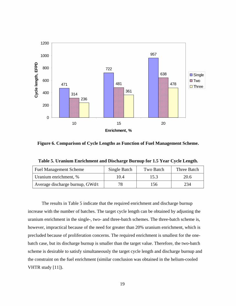
Table 5. Uranium Enrichment and Discharge Burnup for 1.5 Year Cycle Length .......19

Table 6. Sensitivity Results of Maximum Power Density .............................................21

Table 7. Comparison of Void Reactivity Coefficients (pcm/%void) ............................24

Table 8. Comparison of Liquid-Salt-Cooled VHTR Design Data ................................28

Table 9. Normalized Reaction Rate Variations and CVRCs .........................................30

v

List of Figures

Page

Figure 1. Radial Layouts of Helium-Cooled VHTR and LS-VHTR Cores ...................6

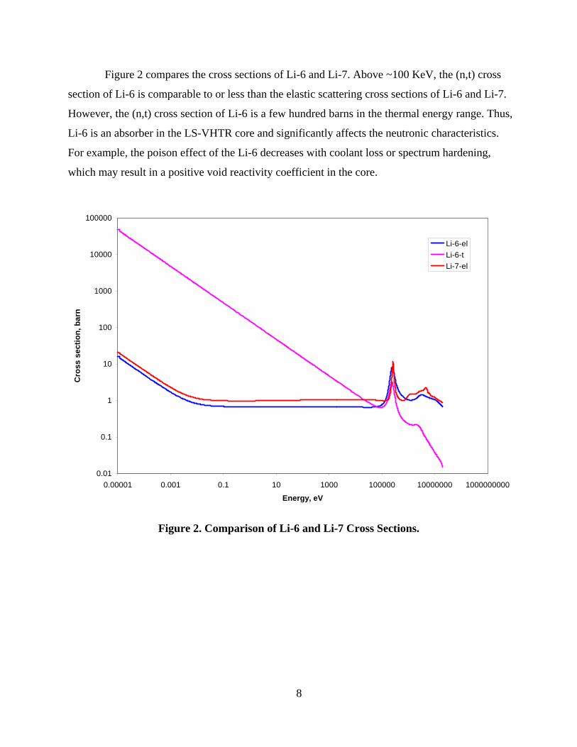
Figure 2. Comparison of Li-6 and Li-7 Cross Sections ................................................8

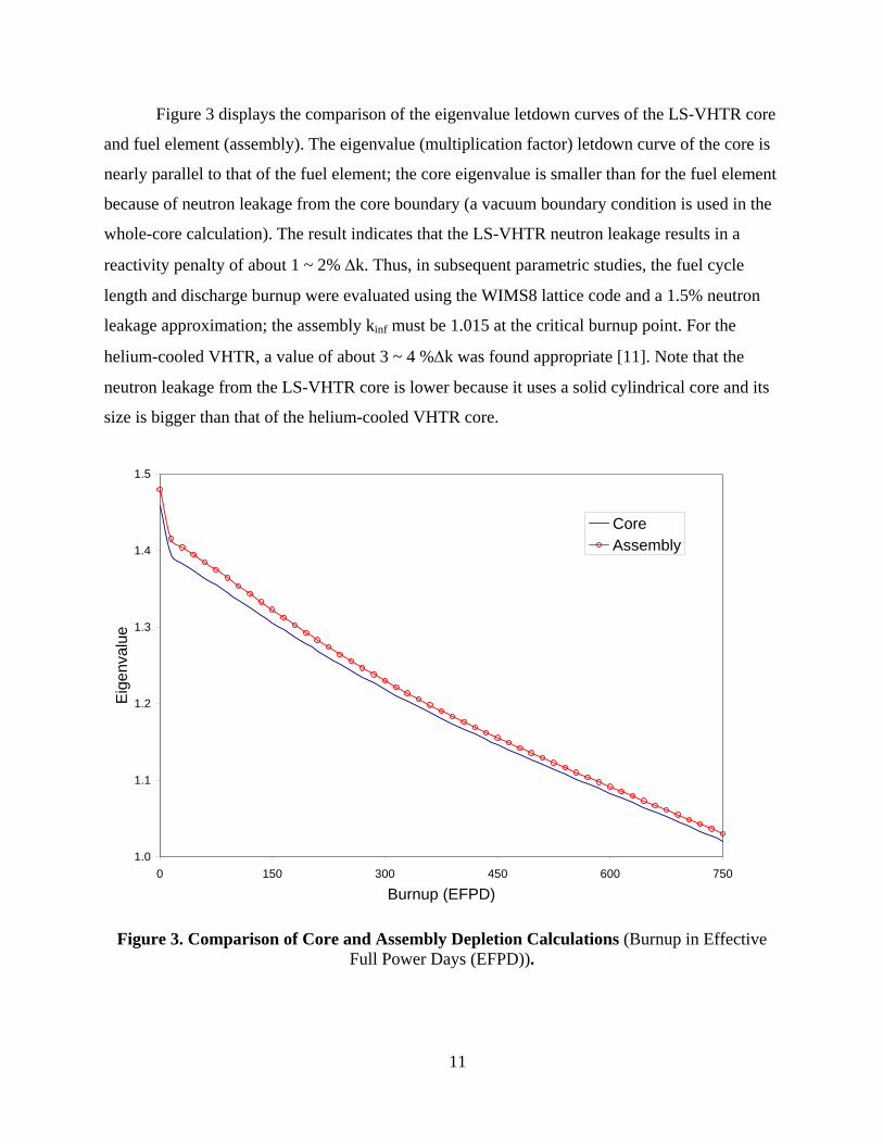
Figure 3. Comparison of Core and Assembly Depletion Calculations ........................11

Figure 4. WIMS8 Procedure for VHTR Full-Assembly Calculation...........................14

Figure 5. Cycle Length as Function of Packing Fraction and Uranium Enrichment ...18

Figure 6. Comparison of Cycle Lengths as Function of Fuel Management Scheme...19

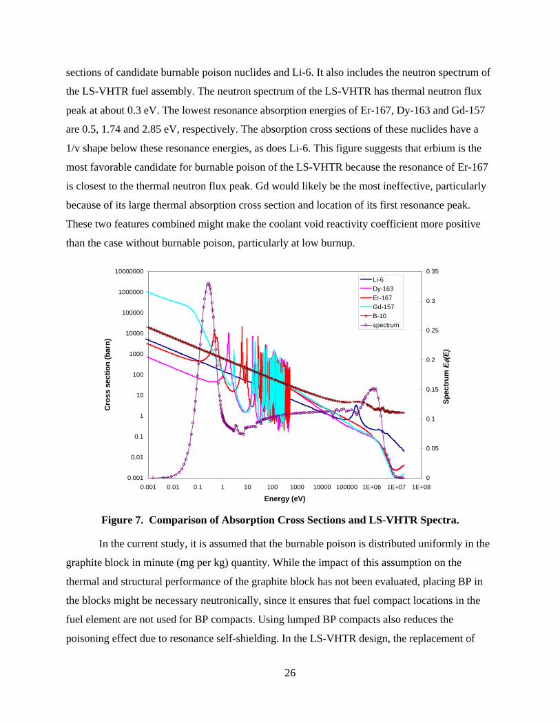
Figure 7. Comparison of Absorption Cross Sections and LS-VHTR Spectra .............26

Figure 8. Impact of Burnable Poisons on CVRC .........................................................27

Figure 9. Comparison of Spectra of Un-Voided States................................................29

Figure 10. Spectra of Un-Voided and Voided States of Large Coolant Hole Case .......31

vi

1

Abstract

Preliminary neutronic studies have been performed in order to provide guidelines to the design of a liquid-salt cooled Very High Temperature Reactor (LS-VHTR) using Li2BeF4 (FLiBe) as coolant and a solid cylindrical core. The studies were done using the lattice codes (WIMS8 and DRAGON) and the linear reactivity model to estimate the core reactivity balance, fuel composition, discharge burnup, and reactivity coefficients. An evaluation of the lattice codes revealed that they give very similar accuracy as the Monte Carlo MCNP4C code for the prediction of the fuel element multiplication factor (kinf) and the double heterogeneity effect of the coated fuel particles in the graphite matrix.

The loss of coolant from the LS-VHTR core following coolant voiding was found to result in a positive reactivity addition, due primarily to the removal of the strong neutron absorber Li-6. To mitigate this positive reactivity addition and its impact on reactor design (positive void reactivity coefficient), the lithium in the coolant must be enriched to greater than 99.995% in its Li-7 content. For the reference LS-VHTR considered in this work, it was found that the magnitude of the coolant void reactivity coefficient (CVRC) is quite small (less than $1 for 100% voiding). The coefficient was found to become more negative or less positive with increase in the lithium enrichment (Li-7 content). It was also observed that the coefficient is positive at the beginning of cycle and becomes more negative with increasing burnup, indicating that by using more than one fuel batch, the coefficient could be made negative at the beginning of cycle. It might, however, still be necessary at the beginning of life to design for a negative CVRC value. The study shows that this can be done by using burnable poisons (erbium is a leading candidate) or by changing the reference assembly design (channel dimensions) in order to modify the neutron spectrum.

Parametric studies have been performed to attain targeted cycle length of 18 months and discharge burnup greater than 100 GWd/t with a constraint on the uranium enrichment (less than 20% to support non-proliferation goals). The results show that the required uranium enrichment and discharge burnup increase with the number of batches. The three-batch scheme is, however, impractical because the required uranium enrichment is greater than 20%. The required enrichment is smallest for the one-batch case, but its discharge burnup is smaller than the target value. Therefore, the two-batch scheme is desirable to satisfy simultaneously the target cycle length and discharge burnup. It was additionally shown that to increase the core power density to 150% of the reference core value, the required uranium enrichment is less than 20% in the single-batch scheme. This higher power density might not be achievable in the two- or three-batch schemes because the fuel enrichment would exceed 20%.

2

3

1. INTRODUCTION

The gas-cooled, graphite-moderated Very High Temperature Reactor (VHTR) is a

leading candidate for the Next Generation Nuclear Power Plant (NGNP). Both helium-cooled

prismatic-block and pebble-bed designs have been considered. [1] Recently, a liquid-salt

(molten-salt) cooled version of the prismatic-block type VHTR, the LS-VHTR, has been

proposed to improve the system economy for the NGNP. This latter concept preserves most of

the attributes of the helium-cooled VHTR such as use of coated particle fuels dispersed in a

graphite matrix, a passively safe reactor system, and a high thermal efficiency derived from a

Brayton power cycle. [2]

A liquid-salt coolant has many favorable properties compared to helium that translate into

advantages for the LS-VHTR. The advantages include lower operating pressure, higher power

density, better heat removal properties, and reduced shielding requirements for external

components. [2] These generally result in improved system safety and the potential for cost

reduction. The disadvantages of the LS-VHTR arise from potential material compatibility issues,

tritium production, activation of the molten salt, higher corrosion rates, chemical hazard (Be

release or HF production from fluoride and tritium), possibility of a positive void reactivity

coefficient, and a relatively high coolant melting temperature.

Work is ongoing at U.S. national laboratories (ANL, INL, ORNL, and SNL) to design a

viable LS-VHTR system that could be used for electricity and/or hydrogen production. This

work is being led by ORNL and is being done in parallel to R&D activities for the helium-cooled

VHTR. The effort would allow the LS-VHTR to be developed to a stage that ensures a fair

comparison of its performance and attributes to those of the helium-cooled VHTR. An aspect of

this national effort is reactor physics studies to provide guidelines to the LS-VHTR design,

particularly as relates to reactor designs and safety issues. Parametric studies have been

performed at ANL to investigate potential values for some of the pertinent core design and

performance parameters. The parameters that have been considered in the study include (1) the

maximum power density possible from a neutronics viewpoint, (2) favorable coolant void

reactivity coefficient (CVRC) from a core safety viewpoint, and (3) estimates of the fuel design

parameters to ensure that cycle length and burnup requirements are met. The results of that study

4

are summarized in this report. It is planned that the findings of this study would be combined

with those from the other laboratories into a single report to be compiled and edited by ORNL.

In Section 2, the characteristics of the LS-VHTR core and fuel element are briefly

described. The lattice physics tools and models employed in this study are discussed in Section 3.

The results of sensitivity and parametric studies are summarized in Sections 4 to 6. The required

enrichment and the neutronically feasible maximum power density for different fuel

management schemes are discussed. The trends in the CVRC and approaches for making it more

negative are also presented. Finally, the conclusions from the work are provided in Section 7.

5

2. LIQUID-SALT-COOLED VHTR CORE AND FUEL ELEMENT DESIGN

The core design of the LS-VHTR borrows significantly from that of the helium-cooled

block-type VHTR design and as such, the LS-VHTR design is derived mainly by replacing the

helium gas coolant with liquid-salt coolant. Thus, the primary LS-VHTR design parameters [3]

have been derived from a previous helium-cooled block-type VHTR point design [1] and the

General Atomics design for the Gas Turbine-Modular Helium Reactor (GT-MHR) [4]. Based on

the findings of the preliminary studies performed in FY 2004, [5] Li2BeF4 (FLiBe) has been

considered a reference liquid salt coolant for the current study. Due to the better heat transport

capability of FLiBe, the LS-VHTR can be operated near atmospheric pressure and would allow a

solid cylindrical core rather than the annular core of the helium-cooled VHTR, which was

determined from a passive decay heat removal perspective. The reference LS-VHTR core was

obtained by loading fuel columns into the inner reflector region of the VHTR. The total power

and power density of the reference LS-VHTR are 2400 MWt and 10.2 MW/m3, respectively,

compared to 600 MWt and 6.6 MW/m3, for the helium-cooled VHTR. [1]

The layouts of the helium-cooled VHTR and the reference LS-VHTR are compared in

Figure 1. The helium-cooled VHTR core has 102 fuel columns located in rings 6, 7, and 8, while

the inner reflector region contains fuel columns in the LS-VHTR core. Thus, the total number of

fuel columns increases to 265 in the latter core. The height of the active core is kept the same as

that of the helium-cooled VHTR (i.e., 7.93 m). Similarly to the helium-cooled VHTR, each fuel

column contains 10 axial fuel elements. Each fuel element contains holes for fuel and burnable

compacts, and full-length channels for coolant flow. Both cores have removable columns in rings

9 and 10. Beyond the outer removable columns are the permanent side reflectors.

The design parameters of the helium-cooled VHTR and LS-VHTR are compared in

Table 1. The same fuel element data for the helium-cooled VHTR have been assumed for the

LS-VHTR, except for the diameter of the coolant hole. The axial dimension of the fuel and

graphite elements is 79.3 cm. The principal fuel element structural material is H-451 graphite

(density is 1.74 g/cm3) in the form of a right hexagonal prism, with a flat-to-flat width of 36 cm.

The standard fuel element contains a regular pattern of fuel and coolant channels. The pitch of

the coolant hole or fuel compact is 1.8796 cm. Similarly to the helium-cooled VHTR, the

LS-VHTR fuel is contained in coated fuel particles (TRISO) which are dispersed in graphite

6

compacts and are in turn contained in holes in the fuel elements. For this study, the fuel form,

kernel size, and thicknesses of coating materials are kept the same as for the helium-cooled

VHTR, but the pertinent enrichment and packing fraction were derived. The fuel form is

assumed as uranium oxy-carbide (UC0.5O1.5). This fuel form has been considered for the NGNP

because it minimizes kernel migration at high temperature. A fuel compact has a diameter of

1.245 cm and a height of 4.93 cm. The fuel element contains 216 fuel compacts and 108 coolant

holes. In this work, the lumped burnable absorber rods have not been modeled; in one study,

however, it was assumed that burnable poison is smeared homogeneously with the graphite

matrix. Based on the reasoning that the heat transport capability of the molten salt is much better

than that of the helium gas, the size of the coolant channel is decreases from 1.584 cm to 0.953

cm, relative to the helium-cooled VHTR. Finally it is assumed that the Li-enrichment is 99.995%

(weight percent of Li-7 in total Li).

Figure 1. Radial Layouts of Helium-Cooled VHTR (Left) and Reference LS-VHTR (Right) Cores.

7

Table 1. Comparison of Helium-Cooled VHTR and LS-VHTR Design Data.

Helium Cooled VHTR LS-VHTR

Core power, MWt 600 2400

Core power density, MW/m3 6.6 10.2

Active height, cm 793 793

Coolant He Li2BeF4

Fuel element

- width across flats, cm - height, cm - density, g/cm3 - fuel rod channel OD, cm - coolant channel DO, cm - pitch between fuel holes, cm

36.0 79.3 1.74 1.27

1.5875 1.8796

36.0 79.3 1.74 1.27 0.953 1.8796

Fuel compact

- kernel - 1st coating - 2nd coating - 3rd coating - 4th coating

425 μm, UC0.5O1.5, 10.50 g/cm3 Carbon buffer, 100 μm thickness, 1.0 g/cm3 Inner pyretic carbon, 35 μm thickness, 1.90 g/cm3 SiC, 35 μm thickness, 3.2 g/cm3 Outer pyretic carbon, 35 μm thickness, 1.87 g/cm3

Coolant temperature (inlet/outlet, oC) 900 / 1000 900 / 1000

Average temperatures for core calculations (oC) - fuel - graphite - coolant

1027 977 927

1027 977 927

The FLiBe coolant considered in the reference LS-VHTR design has three light elements.

The beryllium (Be) and fluoride (F) each have only one naturally occurring isotope, Be-9 and

F-19, respectively. Lithium (Li) however has two naturally occurring isotopes, Li-6 (7.5%) and

Li-7 (92.5%). For all the Be, F, and Li isotopes, except Li-6, the elastic scattering cross section is

dominant, with a magnitude of a few barns at the thermal energy of 0.0253 eV (Li-7 = 1.0b,

Be=6.2b and F=3.7b). Conversely, Li-6 has a large absorption cross section at thermal energy

(941.1 b) due to the (n,t) reaction.

8

Figure 2 compares the cross sections of Li-6 and Li-7. Above ~100 KeV, the (n,t) cross

section of Li-6 is comparable to or less than the elastic scattering cross sections of Li-6 and Li-7.

However, the (n,t) cross section of Li-6 is a few hundred barns in the thermal energy range. Thus,

Li-6 is an absorber in the LS-VHTR core and significantly affects the neutronic characteristics.

For example, the poison effect of the Li-6 decreases with coolant loss or spectrum hardening,

which may result in a positive void reactivity coefficient in the core.

Figure 2. Comparison of Li-6 and Li-7 Cross Sections.

0.01

0.1

1

10

100

1000

10000

100000

0.00001 0.001 0.1 10 1000 100000 10000000 1000000000

Energy, eV

Cro

ss s

ectio

n, b

arn

Li-6-elLi-6-tLi-7-el

9

3. COMPUTATION METHODS AND MODEL VERIFICATION

While more robust and detailed capabilities have been used at ANL for the previous

calculations for the helium-cooled, prismatic block-type VHTR, a simplified approach was used

to expedite the calculations for this project, given the short duration of the project.

The calculations done for this study have mostly used the lattice codes WIMS8 [7] and

DRAGON [8] and the linear reactivity model (LRM) [6] to represent the LS-VHTR core.

WIMS8 and DRAGON allow treatment of the double heterogeneity effect of the coated fuel

particles in the graphite matrix during assembly-level calculations. Prior to the final calculations,

the performance of the codes were evaluated by comparing the code results with those obtained

using the Monte Carlo code MCNP4C [9].

The LRM assumes that the core reactivity behavior with burnup (keff let-down) is linear

and can be predicted using a series of unit assembly calculations. The approach is particularly

useful for getting estimates of the enrichment requirements and fuel compositions with burnup.

In this regard, estimates of the required fuel enrichment can be obtained for the critical burnup

states (see below). The LRM cannot, however, be used for accurately estimating the core power

peaks. The key assumption of the model was verified by comparing the multiplication factor

variation with burnup of a unit fuel element (assembly) calculation to that of a whole-core

calculation, and the core leakage impact on the reactivity was estimated.

In the following sections, the linear reactivity model and the two lattice codes and models

are briefly discussed. The results from the codes are then presented and compared to those from

MCNP4C runs for a numerical benchmark based on the reference LS-VHTR assembly design.

3.1 Estimation of Core Reactivity and Cycle Length

If the assumption of a linear relationship between the core excess reactivity and burnup is

acceptable, the linear reactivity model can be used to predict the reactivity behavior of various

multi-batch fuel management schemes. [6] In our approach, assembly-level calculations with

reflective boundary conditions were utilized to model the performance of a reactor loaded

entirely with LS-VHTR fuel and reflector assemblies. In order to represent the whole-core state

10

adequately with an assembly-level calculation, however, the effect of neutron leakage through

the core boundary was estimated from a whole-core calculation (see below in this paragraph).

The linear reactivity model [6] assumes that the burnup-dependent excess reactivity

varies linearly with burnup. With this assumption, a relationship can be derived to link the

discharge burnup to the core critical burnup (the core average burnup at the end of cycle (EOC)).

Ref. 6 gives the relationship between the core critical burnup ( cB ) and the assembly discharge

burnup ( dB ) as,

dc Bn

nB2

1+= , (1)

where n denotes the number of fuel management batches.

In a three-batch core with a cycle burnup of 33.3 GWd/t, the discharge burnup is 100

GWd/t, and according to Equation 1, the critical burnup is 66.67 GWd/t.

In order to confirm the adequacy of the linear reactivity model and to derive an estimate

for the core leakage to be used in the model, a whole-core WIMS8/DIF3D/REBUS-3 [10]

depletion model of the reference LS-VHTR core was developed and used. The determination of

the leakage effect and the verification of the LRM were then done by comparing the results of

the whole-core model to that of the WIMS8 assembly calculation using a reflective boundary

condition. The initial fuel composition of both cases is the same.

For the WIMS8/DIF3D/REBUS-3 calculations, a 23-group cross section file containing

data for different burnup points was generated at the core average temperatures (fuel, graphite

and coolant temperatures are 1300, 1250, and 1200 K, respectively) using the WIMS8 code. The

REBUS-3 code solves the whole-core depletion problem using the DIF3D nodal option as the

flux solver. Each fuel element is explicitly modeled as a burn-zone; there are 2,560 burn zones

with 256 radial and 10 axial zones. A simplified lumped fission products (LFP) model, which

was developed for previous helium-cooled VHTR core analysis [11] was used in order to save

computation time.

11

Figure 3 displays the comparison of the eigenvalue letdown curves of the LS-VHTR core

and fuel element (assembly). The eigenvalue (multiplication factor) letdown curve of the core is

nearly parallel to that of the fuel element; the core eigenvalue is smaller than for the fuel element

because of neutron leakage from the core boundary (a vacuum boundary condition is used in the

whole-core calculation). The result indicates that the LS-VHTR neutron leakage results in a

reactivity penalty of about 1 ~ 2% Δk. Thus, in subsequent parametric studies, the fuel cycle

length and discharge burnup were evaluated using the WIMS8 lattice code and a 1.5% neutron

leakage approximation; the assembly kinf must be 1.015 at the critical burnup point. For the

helium-cooled VHTR, a value of about 3 ~ 4 %Δk was found appropriate [11]. Note that the

neutron leakage from the LS-VHTR core is lower because it uses a solid cylindrical core and its

size is bigger than that of the helium-cooled VHTR core.

1.0

1.1

1.2

1.3

1.4

1.5

0 150 300 450 600 750

Burnup (EFPD)

Eig

enva

lue

CoreAssembly

Figure 3. Comparison of Core and Assembly Depletion Calculations (Burnup in Effective Full Power Days (EFPD)).

12

3.2 Deterministic Lattice Codes and Models

The WIMS8 code provides an extensive software package for neutronics calculations.[7]

The code employs an open structure that permits the linking of various methods to create a

calculational scheme for a given thermal reactor design. These could range from simple

homogeneous cells to complex whole-core calculations. Most generally, however, the lattice

capabilities of the code are used for reactor analysis. Geometries are available for analyzing

PWR, BWR, VVER, AGR, RBMK, CANDU, other reactor core designs, storage pools, and

experiments.

Methods for the neutron flux solution in WIMS8 include collision probability (1-D or

2-D), method of characteristics, Sn method (1-D or 2-D), diffusion theory, and hybrid methods.

The code also provides an integrated Monte Carlo method (MONK) for the purpose of internal

validation. WIMS8 is supplied with 69- and 172-group libraries based on the validated JEF2.2

nuclear data. It is noted that the WIMS8 code has the PROCOL module that provides a

capability for calculating the collision probabilities of particulate fuel in an annular geometry

that could be used in flux solvers to model the double heterogeneity effect of that fuel form.

The DRAGON code has a collection of models for simulating the neutronic behavior of

a unit cell or a fuel lattice in a nuclear reactor.[8] The typical functionalities found in most

modern lattice codes are contained in DRAGON. These include interpolation of microscopic

cross sections supplied by means of standard libraries; resonance self-shielding calculations in

multidimensional geometries; multigroup and multidimensional neutron flux calculations which

can take into account neutron leakage; transport-transport or transport-diffusion equivalence

calculations; and modules for editing condensed and homogenized nuclear properties for reactor

calculations.

The current version of the code contains three algorithms for the solution of the integral

transport equation, ranging from a simple collision probability method coupled with the interface

current method to the full collision probability method. The code also performs isotopic

depletion calculations. The code user must however supply cross sections in one of the following

standard formats: DRAGON, MATXS (TRANSX-CTR), WIMSD4, WIMS-AECL, and

APOLLO. Macroscopic cross sections can also be read by DRAGON via the input data stream.

13

At ANL, the 69- and 172-group cross section libraries created in WIMSD4-format by the

Reduced Enrichment for Research and Test Reactors (RERTR) project are used with the

DRAGON code. The depletion chains and types of fission products to be tracked by the code are

obtained from the cross section library used. For the DRAGON calculations, cross section data

for the heavy nuclides are tabulated at different temperatures (2-4 points) and all the heavy

nuclides contained in the library are treated as resonance materials.

An attractive feature of the DRAGON code is its ability to treat particulate fuel in a

graphite matrix in a full-assembly calculation. This capability has been used for modeling the

fuel assemblies of block-type, high-temperature gas-cooled thermal reactors and the pebble

elements in alternative pebble-bed concepts.

It is noted that in the DRAGON full-assembly model for VHTR hexagonal block, the

block is formed by a collection of pin-cell sized hexagons. Each pin-cell contains the fuel

compact and its surrounding block graphite. When all the fuel and coolant-hole pin-cells are

represented, the block graphite content is not totally accounted for and therefore an extra ring of

pin-cell sized hexagons is used to represent the remaining graphite. The number density of the

graphite in these peripheral cells is modified to preserve the graphite content of the assembly

block. Due to the use of the pin-cell sized hexagons, the DRAGON assembly model has jagged

boundaries, not the flat boundaries of the hexagonal block.

A distinction between the DRAGON and WIMS8 models for the VHTR assembly is that

the WIMS8 code does not provide the particulate-fuel double heterogeneity treatment at the

assembly level like DRAGON. A two-step scheme is therefore utilized in the WIMS8

calculation. In the first step, the PROCOL module is used for detailed treatment of the double

heterogeneity at the pin-cell level; other items, such as Doppler and resonance treatments are

considered. A super-cell calculation is performed at this stage. The super-cell model is prepared

by converting the hexagonal unit pin-cell to an equivalent annular cell and introducing an extra

region representing a fraction of the graphite block outside the fuel cells. The fraction is

determined such that the graphite volume in the super-cell is equal to the ratio of the graphite

block volume to the number of fuel cells. The result of the pin-cell calculation is homogenized

fuel pin-cell cross sections. These cross sections are then used in the second step, which

14

embodies the full-assembly calculation. Besides the homogenized geometry of the fuel pin-cell,

the detailed geometries of the other cells are retained in the assembly calculation. The full-

assembly calculation is performed using the CACTUS module of the WIMS8 code. A schematic

of the two-step procedure is provided in Figure 4.

3.3 Lattice Code Verification by Comparison to Monte Carlo Results

Previous study has been performed to evaluate the performance of the WIMS8 and

DRAGON code models for the analysis of the helium-cooled VHTR. The study demonstrated

that the codes are capable of calculating lattice parameters of interest very accurately compared

to Monte Carlo reference solutions in the range of interest. [12] While the helium-cooled VHTR

Figure 4. WIMS8 Procedure for VHTR Full-Assembly Calculation.

Fuel compact

Coolant

Graphite

Buffer

PROCOLgenerate

resonance XS

Assignment of XS toeach location

CACTUS or PERSEUSsolve transport equation

15

and the liquid-salt cooled VHTR employ the same assembly design, the different characteristics

of the coolants suggest the need for further verification of the performance of the lattice codes.

The performances of the deterministic lattice codes WIMS8 and DRAGON for analyzing

the LS-VHTR fuel element have been evaluated by comparing results from the codes to those

from the Monte Carlo code MCNP4C. The MCNP4C calculations for the fuel assembly were

performed using the ENDF/B-VI nuclear data library distributed with the code. The calculations

were for the cold state (293oK) and have been performed without S(α,β) data for the light

nuclides in the liquid-salt coolant because the data do not exist currently in both the MCNP4C

and the deterministic codes. In the WIMS8 and DRAGON calculations, the 172 group transport

equations were solved.

In this study, the packing fraction, uranium enrichment and coolant-hole diameter are

25%, 10% and 0.953 cm respectively; the values suggested for the reference LS-VHTR design.

A lithium enrichment value of 99.995% was used. Results from the study are summarized in

Tables 2 and 3. In addition to the traditional element eigenvalue, an estimate of the double

heterogeneity effect was also obtained. This effect was determined by taking the difference in the

multiplication factor (kinf) values derived from calculations using the spatially heterogeneous and

homogeneous compact models. In the heterogeneous model the coated fuel particles are

explicitly represented in the compact. On the other hand, in the homogeneous model, the

compositions of the coated fuel particles are smeared with those of the graphite matrix using

volume weighting. In the latter model, the self-shielding effect of the fuel at the particle level is

not represented.

Table 2 summarizes the eigenvalues calculated by the WIMS8 and DRAGON lattice

codes and the MCNP4C Monte-Carlo code. The WIMS8 and DRAGON codes calculated fuel

element kinf values that are within 100 pcm and 200 pcm, respectively, of those from MCNP4C

calculations. (The reactivity differences were computed using Δρ = Δk/k1k2.) Components of

these differences come from the different nuclear data files used in the calculations (e.g., JEF2.2

for WIMS8). These differences are similar to those observed during the NGNP sensitivity study

performed in FY 2004 [12].

16

Table 2. Comparison of kinf Values for Fuel Element at Cold State.

Compact model Li Enrichment Code Eigenvalue Difference from

reference, pcm Δρ MCNP4C 1.53861 ± 0.00067 a) Reference WIMS8 1.53756 -44 Heterogeneous 99.995 %

DRAGON 1.53832 -12 MCNP4C 1.47886 ± 0.00075 Reference WIMS8 1.47681 -94 Homogeneous 99.995 %

DRAGON 1.48216 151 a) 1.53867 ± 0.00075 with MCNP5

The deterministic and Monte Carlo codes predicted very similar values for the double

heterogeneity effect in the LS-VHTR fuel element (difference in kinf from calculations using the

smeared and explicit heterogeneous fuel compact models). The MCNP4C calculation predicted a

value of 2.6%Δρ and the two lattice codes give a deviation of about 0.1%Δρ for these cases (see

Table 3). These are surprisingly small differences. For comparison, an earlier MCNP4C

calculation for the helium-cooled VHTR fuel element gave a value of 2.3%Δρ for the double

heterogeneous effect.

Table 3. Double Heterogeneity Effect (Δρ).

Code Lithium Enrichment (%Li-7 Content) Double Heterogeneity Effect,%Δρ

MCNP4C 99.995 2.6

WIMS8 99.995 2.7

DRAGON 99.995 2.5

Assembly power distributions have not been compared in this verification effort. The

reason is two-fold. First, assembly power distributions have not been used to derive any other

value used in the current study. Additionally, given the similarity in trends between the lattice

kinf values obtained in this evaluation and those previously obtained for the helium-cooled VHTR,

it is expected that very good agreement in power distribution would be obtained, based on the

previous finding for the helium-cooled VHTR [12].

17

4. DISCHARGE BURNUP AND REQUIRED URANIUM ENRICHMENT

Parametric studies have been performed for the LS-VHTR, in order to ensure that the

constraint on the fuel enrichment will be met for an assumed target cycle length of 18 months

and target discharge burnup greater than 100 GWd/t, similarly to those used in recent helium-

cooled VHTR studies. [11] The linear reactivity model developed and discussed in Section 3.1

was used for the study. In this study, the reactor capacity factor and Li-enrichment were assumed

to be 90% and 99.995%, respectively. The kernel diameter was fixed as 425 μm.

First, the cycle length and discharge burnup were evaluated as a function of uranium

enrichment, packing fraction, Li-enrichment, and number of batches. Results from this study are

summarized in Table 4. The cycle lengths obtained for the single-batch cases are plotted in

Figure 5.

Table 4. Cycle Length and Discharge Burnup (LRM with 1.5%Δk Leakage Approximation). Single batch Three batch Uranium

enrichment (%)

Lithium Enrichment

(%) Packing fraction

Specific power density

(W/g HM)

Cycle length

(EFPD)

Discharge burnup

(GWd/t)

Cycle length

(EFPD)

Discharge burnup

(GWd/t) 0.10 396 200 79 100 120 0.20 198 422 83 211 127 10.0 99.995 0.30 132 472 62 236 96 0.10 396 313 124 156 187 0.20 198 644 127 322 194 99.995 0.30 132 731 96 366 148 15.0

99.990 0.20 198 632 125 316 188 0.10 396 420 166 210 251 0.20 198 853 169 427 256 20.0 99.995 0.30 132 983 130 492 198

The overall trends of the LS-VHTR are similar to those for the helium-cooled VHTR [11];

the cycle length increases with uranium enrichment and packing fraction, and the optimum

packing fraction was observed around 25% (see Figure 5). Additionally, the discharge burnup

increases with increase in the number of batches, but the cycle length decreases. The cycle length

is observed to increase with increase in the lithium enrichment; increasing the lithium

enrichment from 99.99% to 99.995% results in an increase of the cycle length by 12 EFPD

(~1.9%) (see the case with an enrichment of 15% and packing fraction of 0.20).

18

0

200

400

600

800

1000

1200

0.10 0.15 0.20 0.25 0.30

Packing fraction

Cyc

le le

ngth

(EFP

D)

E-10%E-15%E-20%

Figure 5. Cycle Length as Function of Packing Fraction and Uranium Enrichment

The cycle lengths of the LS-VHTR as a function of the fuel management scheme (i.e.,

number of batches) and uranium enrichment are plotted in Figure 6. Generally, the cycle length

increases as the uranium enrichment increases, but decreases with increase in the batch size. To

utilize the uranium resources effectively, a high discharge burnup is desirable. By increasing the

batch size, it is possible to increase the discharge burnup; however, the cycle length could

become smaller than the target cycle length. In this study, the target cycle length is assumed to

be 1.5 years. The required uranium enrichment to obtain the target cycle length and the

corresponding discharge burnup were estimated using the data of Figure 6 and the results are

provided in Table 5. In the calculations, the reactor capacity factor and the core power density

were assumed as 90% and 10.2 MW/m3, respectively. A lithium enrichment of 99.995% was

used.

19

471

722

957

314

481

638

236

361

478

0

200

400

600

800

1000

1200

10 15 20

Enrichment, %

Cyc

le le

ngth

, EFP

D

SingleTwoThree

Figure 6. Comparison of Cycle Lengths as Function of Fuel Management Scheme.

Table 5. Uranium Enrichment and Discharge Burnup for 1.5 Year Cycle Length.

Fuel Management Scheme Single Batch Two Batch Three Batch Uranium enrichment, % 10.4 15.3 20.6 Average discharge burnup, GWd/t 78 156 234

The results in Table 5 indicate that the required enrichment and discharge burnup

increase with the number of batches. The target cycle length can be obtained by adjusting the

uranium enrichment in the single-, two- and three-batch schemes. The three-batch scheme is,

however, impractical because of the need for greater than 20% uranium enrichment, which is

precluded because of proliferation concerns. The required enrichment is smallest for the one-

batch case, but its discharge burnup is smaller than the target value. Therefore, the two-batch

scheme is desirable to satisfy simultaneously the target cycle length and discharge burnup and

the constraint on the fuel enrichment (similar conclusion was obtained in the helium-cooled

VHTR study [11]).

20

5. MAXIMUM POWER DENSITY

The better heat transfer property of the FLiBe liquid-salt coolant compared to the helium

coolant is a reason why a solid cylindrical core configuration is being considered for the

LS-VHTR. A solid core is attractive since it allows the increase of the core power level at a fixed

power density and hence the potential for better plant economy, relative to an annular core

design. The good thermal property of FLiBe would also provide an opportunity to increase the

power density. The power density of the reference LS-VHTR is about 50% higher than that of

the helium-cooled VHTR (10.2 versus 6.6 MW/m3). The increase in power density for a fixed

power level improves the economy by reducing the reactor size, but it increases the fuel

depletion rate and thus reduces the cycle length for a fixed fuel loading. A neutronic sensitivity

study has been performed to determine the maximum power density of the LS-VHTR that meets

the cycle length and discharge burnup goals within the constraints on uranium enrichment

(<20%), though core thermal and safety performance would also impact the final value. The

thermal and safety calculations for the LS-VHTR are being performed by INL and would be

reported in a separate deliverable report.

Various power densities were obtained by changing the total number of fuel columns.

The power densities evaluated in this study were obtained by decreasing the number of fuel rings

from 10 (reference value) to 8 rings. The numbers of fuel columns in the cases with 10, 9, and 8

rings are 265, 211, and 169, respectively; note that for cases in which all the rings have no

vacancies, the total number of columns in the core is 3N(N-1)+1, where N is the number of rings.

The cases with 10 and 9 rings are assumed to have six vacant fuel columns (see Figure 1 for the

10-ring case). Note that in the sensitivity calculations performed for this work, it is assumed that

all core columns contain fuel elements only (i.e., no control elements have been modeled).

Additionally, for the calculations, the lithium enrichment and packing fraction are assumed to be

99.995% and 25%, respectively.

The linear reactivity model discussed in Section 3.1 was used in the study. The targeted

cycle length for the study is 18 months. The WIMS8 model developed for the reference core was

modified to reflect the change in the specific power (power density) level resulting from the

decrease of the fuel loading (fuel elements). With this new specific power, the WIMS8 code is

used to determine the enrichment that gives a cycle length of 18 months.

21

The results of the maximum power density study are provided in Table 6. For the purpose

of comparison, the results for the two-batch helium-cooled VHTR core having a power level of

600 MWt and a power density of 6.6 MW/m3 is included in the table. The results indicate that a

higher enrichment is required to increase the power density of the LS-VHTR from the reference

value of 10.2 MW/m3. The constraint on the fuel enrichment (less than 20% for proliferation

reasons) and the targeted discharge burnup (greater than 100 GWd/t) define the neutronic bounds

for the acceptable power density.

Table 6. Sensitivity Results of Maximum Power Density.

Parameter VHTR LS-VHTR Power, MWt 600 2400 Total number of fuel columns 102 265 211 169 Power density, MW/m3 6.6 10.2 12.8 15.9 Specific Power Density, MW/t 103 158 199 248

Enrichment, % 10.4 13.0 16.3 Single-batch Burnup, GWd/t 78 98 122 Enrichment, % 14.0 15.3 19.5 24.7 Two-batch Burnup, GWd/t 100 156 196 244 Enrichment, % 20.6 26.2 33.1 Three-batch Burnup, GWd/t 234 293 366

Note: The case with 265 fuel columns and a power density of 10.2 MW/m3 is the reference LS-VHTR core.

With the single-batch fuel management scheme, only the case with a power density of

15.9 MW/m3 (of the three cases evaluated) meets the targeted cycle length and discharge burnup

and the constraint on the enrichment simultaneously. With the use of higher number of batches,

the discharge burnup is greater than 100 GWd/t for all the cases. However, only for the two-

batch fuel management cases using power densities of 10.2 MW/m3 (reference) and 12.8 MW/m3

is the enrichment limit met. Using higher number of batches or power densities results in a

higher enrichment requirement. It is noted that discrete values of power densities have been used

in this study and that a more detailed study would be required to determine the exact boundaries

of the design space that meets the core design requirements and constraints. However, higher

power densities have not been considered because preliminary thermal and safety calculations

indicate that it would be difficult to retain the passive safety attributes of the core with a much

higher power density than the reference value.

22

Taken as a whole, the results show that neutronically, the reference power density can be

increased by over 50% (from 10.2 to 15.9 MW/m3) when the single-batch fuel management

scheme is employed. This is equivalent to 2.4 times the value for the helium-cooled VHTR

design. Increasing the number of batches is detrimental because of the increase in the enrichment

requirement (could be more than 20%).

23

6. INVESTIGATION OF THE COOLANT VOID REACTIVITY COEFFICIENT

Fundamental reasoning suggests that the removal of the liquid-salt coolant by voiding

would result in a positive reactivity addition. A major contributor to this is the strong absorption

of neutrons by the (n,t) reaction in Li-6. The Li-6 also contributes a positive reactivity

component following the hardening of the neutron spectrum with voiding because of the 1/v

trend in the (n,t) cross section. While the impact of a positive coolant void reactivity coefficient

would have to be quantified by evaluating credible accidents involving coolant voiding, it is

desirable, however that the coefficient be negative in order to meet any stringent regulatory or

plant administrative limits on this parameter.

Previous studies performed in FY 2004 by a team led by ORNL indicated that this

positive reactivity addition could be mitigated by enriching the lithium in the coolant to greater

than 99.99% in its Li-7 content. [5] It was additionally found that of the liquid salts considered at

that time, the FLiBe coolant resulted in the lowest coolant void reactivity coefficient. To provide

additional insights into the coolant void reactivity coefficient (CVRC), this parameter has been

further evaluated in this study. Our study focused on the variation of the CVRC with burnup,

with the use of burnable poison, and the impact of geometry variation on its value. These studies

and the results obtained are discussed in the following sections.

6.1 Impact of Fuel Burnup on the Coolant Void Reactivity Coefficient

Coolant void reactivity coefficients (CVRCs) have been calculated as a function of

burnup for the reference fuel-element design, using the deterministic lattice codes WIMS8 and

DRAGON. The burnup-dependent CVRC were obtained by branch calculations at the burnup

points of interest using full voiding of the coolant to derive the 100% voiding reactivity effect.

The result is then normalized to the reactivity change per percent voiding. Since the CVRC is

meaningful only for the operating condition, Monte Carlo calculations have not been performed

because we presently do not have cross sections at the elevated temperature conditions of the LS-

VHTR; it is beyond the scope of the current effort to generate such cross sections. For the

assembly CVRC study, an assembly fuel enrichment of 15% and fuel packing fraction of 25%

were used. Variation of the lithium enrichment (from the reference value of 99.995% to 99.99%)

was utilized to evaluate the impact of this parameter on the reactivity coefficient result.

24

Results of the study are summarized in Table 7. Noticeable differences are observed in

the CVRC values calculated by the WIMS8 and DRAGON codes. The differences between the

two codes were also found to become larger with burnup. The reason for these differences has

not been completely investigated in the current study. It is however probably due to differences

in basic cross section data (JEF2.2 for WIMS8 and ENDF/B-VI for DRAGON) and differences

in material compositions at burnup points arising from different solution methodology and code

data. It is noted that the magnitude of the differences is actually small, the largest difference

being about 600 pcm over 100% voiding for the case with lithium enrichment of 99.99% and

about 300 pcm over 100% voiding for the case with lithium enrichment of 99.995%. The results

also show that the magnitude of the positive CVRC is small, being less than $1 per 100%

voiding (assuming a delayed neutron fraction value of 600 to 700 pcm). Further evaluations of

the differences with burnup, however, need to be performed.

Table 7. Comparison of Void Reactivity Coefficients, (pcm/%void).

Case with Li enrichment of 99.99% Case with Li enrichment of 99.995%

Burnup (GWd/t) WIMS8 DRAGON WIMS8 DRAGON

0.0 3.6 5.4 0.2 1.5

15.0 3.0 2.9 -0.4 -0.2

30.0 1.6 0.4 -1.8 -2.4

45.0 0.6 -2.0 -3.0 -4.2

60.0 -0.2 -4.2 -4.0 -6.1

90.0 -1.0 -7.1 -5.3 -8.6

Additionally, the results indicate that the WIMS8 and DRAGON codes give similar

trends for the CVRC. It is observed that the coefficient is positive at the beginning of cycle and

decreases with increasing burnup. At a burnup between 15 and 20 GWd/t, the fuel element

CVRC becomes negative in the case using a lithium enrichment of 99.995%. This suggests that

by using more than one fuel batch, the coefficient could be made negative. This has to be

confirmed in future studies with whole-core models. It is expected that the unit element CVRC

values presented in Table 7 are actually more positive (i.e. higher) than those that would be

obtained from whole-core calculations, because neutron leakage tends to reduce the CVRC.

25

Furthermore, the results show that the CVRC is dependent on the lithium enrichment. The

coolant void reactivity coefficient for the 99.99% lithium enrichment case is more positive than

that for the case with a lithium enrichment of 99.995%.

The reduction of the CVRC value with burnup is due to the decrease in the neutron

absorption in lithium arising from the competition with other absorbers (fission products) created

as part of the fission process. It is also noted that the spectrum hardens with burnup which further

enhances the reduction. The decrease of the CVRC with increasing lithium enrichment results

primarily from the reduction of the neutron absorption in Li-6. Clearly, one approach to reduce

the CVRC is to increase the lithium enrichment. This could however be costly.

6.2 Reduction of the CVRC with Burnable Poisons

The results presented in Section 6.1 show that the CVRC is reduced with increase in the

Li-7 content (Li enrichment) of the FLiBe liquid-salt coolant and with burnup. The trend with

burnup suggests that the void reactivity coefficient of a multi-batch core could be negative at the

beginning and throughout the equilibrium cycle. This trend does not however preclude the fact

that a solution must be found for the coolant void reactivity coefficient of the initial core.

Burnable poisons have therefore been suggested as a means of ensuring a negative void

reactivity coefficient for the LS-VHTR. Generally, burnable poisons are used in reactor designs

to compensate the excess reactivity (reduce the control rod worth requirements) and to suppress

core power peaks. In the helium-cooled VHTR, the control of power peaks using burnable

absorber is very important because high power values would develop otherwise at the interface

between the core and the inner reflector. This power peak suppression role is less important in

the LS-VHTR because of the use of the solid cylindrical core. However, a burnable poison could

prove useful for reducing the CVRC and hence the performance of typical burnable poison (BP)

has been evaluated in this study.

From physics reasoning, the introduction of the BPs provides competition for neutron

absorption in lithium and thus reduces the impact of the loss of coolant (primarily Li-6 effect) on

the void reactivity coefficient. A burnable poison having appropriately located thermal

absorption resonances could make the void reactivity coefficient negative following neutron

spectral hardening arising from the coolant voiding. Figure 7 is a plot of the absorption cross

26

sections of candidate burnable poison nuclides and Li-6. It also includes the neutron spectrum of

the LS-VHTR fuel assembly. The neutron spectrum of the LS-VHTR has thermal neutron flux

peak at about 0.3 eV. The lowest resonance absorption energies of Er-167, Dy-163 and Gd-157

are 0.5, 1.74 and 2.85 eV, respectively. The absorption cross sections of these nuclides have a

1/v shape below these resonance energies, as does Li-6. This figure suggests that erbium is the

most favorable candidate for burnable poison of the LS-VHTR because the resonance of Er-167

is closest to the thermal neutron flux peak. Gd would likely be the most ineffective, particularly

because of its large thermal absorption cross section and location of its first resonance peak.

These two features combined might make the coolant void reactivity coefficient more positive

than the case without burnable poison, particularly at low burnup.

0.001

0.01

0.1

1

10

100

1000

10000

100000

1000000

10000000

0.001 0.01 0.1 1 10 100 1000 10000 100000 1E+06 1E+07 1E+08

Energy (eV)

Cro

ss s

ectio

n (b

arn)

0

0.05

0.1

0.15

0.2

0.25

0.3

0.35

Spec

trum

Eφ(

E)

Li-6Dy-163Er-167Gd-157B-10spectrum

Figure 7. Comparison of Absorption Cross Sections and LS-VHTR Spectra.

In the current study, it is assumed that the burnable poison is distributed uniformly in the

graphite block in minute (mg per kg) quantity. While the impact of this assumption on the

thermal and structural performance of the graphite block has not been evaluated, placing BP in

the blocks might be necessary neutronically, since it ensures that fuel compact locations in the

fuel element are not used for BP compacts. Using lumped BP compacts also reduces the

poisoning effect due to resonance self-shielding. In the LS-VHTR design, the replacement of

27

fuel compacts with BP compacts might result in quite high uranium enrichment requirement or

the inability to meet the cycle length requirement. (It might however be necessary, for the sake of

completeness, to consider the use of BP compacts in future studies.)

In Figure 8, the void reactivity coefficients are compared for LS-VHTR fuel elements

using the different BP nuclides. In these calculations, the BP content in the graphite block is

assumed 150 ppm for the rare elements, but only 15 ppm for boron in order to have similar BP

number densities in the graphite blocks of the cases. (Note that the atomic weights of boron

isotopes are about one-tenth of those of the rare isotopes.) As expected, Gd increases the coolant

void reactivity coefficient at low burnup while other BP nuclides decrease the coolant void

reactivity coefficient, relative to the no-BP case. At low burnup, the use of erbium gives the most

negative void reactivity coefficient, compared to the other candidates. The competition with

fission product nuclides and other irradiation products (e.g., plutonium and minor actinides) is

the reason why Dy appears attractive at high burnup. However, since the BPs burn out quickly,

the void reactivity coefficients for the cases are comparable to the no-BP case after a burnup of

15 GWd/t.

-8.0

-6.0

-4.0

-2.0

0.0

2.0

4.0

6.0

8.0

10.0

12.0

0.0 15.0 30.0 45.0 60.0 90.0

Burnup (GWd/t)

Void

Rea

ctiv

ity C

oeffi

cien

t (pc

m/%

void

) No BPErGdDyB

Figure 8. Impact of Burnable Poisons on CVRC.

28

6.3 Spectrum Effect on the Coolant Void Reactivity Coefficient

The use of neutron spectrum variation to make the void reactivity coefficient more

negative has been evaluated. The spectrum was changed by varying the fuel-to-moderator ratio

(i.e., increasing the diameter of the coolant hole or increasing the total number of fuel pins). The

changes in the design parameters and the results are summarized in Table 8. These variations in

core parameters would affect the thermal hydraulic and safety characteristics of the reactor. At

this point, however, only the impacts on the neutronics characteristics have been evaluated to

provide guidelines for the void reactivity coefficient as a function of neutron spectrum. The

primary design data of the three cases are fairly the same except for the total number of fuel pins

(as well as coolant holes) and coolant hole diameter. The total number of fuel pins is increased to

234 (the total number of coolant holes decreases to 90) in the many-fuel-pin case and the

diameter of the coolant hole in the large-coolant-hole case is increased to that of the diameter of

the current helium-cooled VHTR design.

Table 8. Comparison of Liquid-Salt-Cooled VHTR Design Data.

Case Reference case

Many fuel pins

Large coolant hole

Core power, MWt 2400 2400 2400

Total number of fuel pins in assembly 216 234 216

Total number of coolant holes in assembly 108 90 108

Fuel rod channel OD, cm 1.27 1.27 1.27

Coolant channel OD, cm 0.953 0.953 1.5875

Pitch between fuel holes, cm 1.8796 1.8796 1.8796

Specific power density, W/g 158 146 158

Kernel diameter, μm 425 425 425

Packing Fraction, % 25 25 25

Initial kinf 1.4749 1.4549 1.4335

Reactivity swing, %Δρ 30.8 29.9 28.9

Discharge burnup of two-batch core, GWD/t 156 144 138

Cycle length of two-batch core, EFPD 494 494 435

29

The spectra of the three cases are compared in Figure 9. The increase in the total number

of fuel pins or the change to a larger coolant-hole diameter results in a reduction of the thermal

flux and an increase in the epithermal flux. Since Li and F-19 have resonances at ~250 keV and

~27 keV respectively, the resonance effects of the coolant constituents are observed for the large

coolant hole case. The spectrum changes affect the core neutronic performance and

characteristics as indicated by the results provided in Table 8. For the large coolant-hole case,

the initial kinf and the cycle length decrease compared to those of the reference case (435 EDPD

versus 494 EFPD) because the poison effect of the coolant increased. For the many fuel pin case,

the initial kinf and discharge burnup decrease compared to those of the reference case, but the

cycle length is similar due to the smaller specific power density.

0.00

0.05

0.10

0.15

0.20

0.25

0.30

0.35

1.0E-03 1.0E-02 1.0E-01 1.0E+00 1.0E+01 1.0E+02 1.0E+03 1.0E+04 1.0E+05 1.0E+06 1.0E+07

Energy (eV)

Nor

mal

ized

Eφ(

E)

ReferenceLarge holeMany pins

Figure 9. Comparison of Spectra of Un-Voided States.

The fuel-element CVRC and reaction rate variations are summarized in Table 9. The

reaction rates have been normalized to the corresponding total reaction rate of the un-voided

state. The neutron production rate of U-235 decreases with coolant voiding while the neutron

production rate of U-238 increases by the same magnitude. Thus, the total neutron production

rate is unchanged. The total neutron absorption rate is dependent on the fuel element designs.

30

The normalized neutron absorption rates of the heavy metal and graphite increase with coolant

voiding, while that of the coolant decreases. Thus, the balance of the neutron absorption rates of

the coolant and other materials determines the sign of the void reactivity coefficients.

Table 9. Normalized Reaction Rate Variations and CVRCs.

Reference case Many fuel pins Larger coolant hole

Absorption Production Absorption Production Absorption Production

Change of reaction rate due to coolant voiding (%) at 0 GWd/t Burnup

Graphite 0.02 0.01 0.04 Coolant -0.89 -0.68 -2.38

U235 0.10 -0.03 0.09 -0.03 0.36 -0.09 U238 0.75 0.03 0.66 0.03 2.47 0.09

Total -0.02 0.00 0.09 0.00 0.49 0.00

Void reactivity coefficient (pcm/% voided)

0 GWd/t 0.2 -0.5 -3.2

15 GWd/t -0.4 -1.1 -5.6

30 GWd/t -1.8 -2.4 -10.7

60 GWd/t -4.0 -4.6 -19.1

90 GWd/t -5.3 -5.9 -25.0

For the reference case, the total neutron absorption rate decreases with coolant voiding

because coolant poison effect is larger than those of other materials. Thus, the void reactivity of

the reference case is positive. For the many fuel pin case, the CVRC is negative because the total

absorption rate increases slightly. For the large hole case, the neutron absorption rate changes

more significantly. In particular, the absorption rate of U-238 increases and it is larger than the

coolant poison effect (2.47 versus 2.38). Thus, the void reactivity coefficient becomes more

negative compared to the other cases. The increase of the U-238 absorption rate can be

understood when the spectra of the un-voided and voided cases are compared (see Figure 10);

the spectrum hardening due to coolant voiding increases the U-238 resonance capture.

In conclusion, these results show that a more negative void reactivity coefficient can be

obtained by hardening of the neutron spectrum, relative to the reference design.

31

0.00

0.05

0.10

0.15

0.20

0.25

0.30

0.35

1.0E-03 1.0E-02 1.0E-01 1.0E+00 1.0E+01 1.0E+02 1.0E+03 1.0E+04 1.0E+05 1.0E+06 1.0E+07

Energy (eV)

Nor

mal

ized

Eφ(

E)

Large holeLarge hole-void

Figure 10. Spectra of Un-Voided and Voided States of Large Coolant Hole Case.

32

7. CONCLUSIONS

Preliminary neutronic evaluations for the LS-VHTR have been performed using the

deterministic lattice codes (WIMS8 and DRAGON) and the linear reactivity model to evaluate

core reactivity balance, fuel composition with burnup, discharge burnup and the coolant void

reactivity coefficient. First, the performance of the lattice codes was investigated by comparing

the code results to those obtained using the Monte Carlo code, MCNP4C. It was found that the

codes predict very similar eigenvalue and fuel double heterogeneity effect.

The cycle length and discharge burnup were evaluated as a function of uranium

enrichment, packing fraction, Li-enrichment, and number of batches. The overall trends of these

parameters for the LS-VHTR were found similar to those of the helium-cooled VHTR; the cycle

length increases with uranium enrichment and packing fraction, and the optimum packing

fraction was observed around 25%. The cycle length increases slightly when the Li-enrichment is

increased from 99.99% to 99.995%.

The required uranium enrichment to obtain the target cycle length (18 months) and the

corresponding discharge burnup were determined from parametric studies. The results indicate

that the required uranium enrichment and discharge burnup increase with the number of batches.

The three-batch scheme is, however, impractical because the required uranium enrichment is

greater than 20%, which is precluded because of proliferation concerns. The required enrichment

is smallest for the one-batch fuel management scheme, but its discharge burnup is smaller than

the target value (100 GWd/t). Therefore, the two-batch scheme is desirable to satisfy

simultaneously the target cycle length and discharge burnup and the enrichment (similar

conclusion was obtained in the helium-cooled VHTR study).

The maximum power density of the LS-VHTR was investigated for the single-, two-, and

three-batch schemes. A higher enrichment is necessary to increase the power density of the

LS-VHTR. To increase the power density to 150 % of the reference core, the required uranium

enrichment is less than 20% in the single-batch fuel management scheme, while it is impractical

to increase the power density to this level in the two- or three-batch schemes because the

enrichment would exceed 20%.

33

The coolant void reactivity coefficient (CVRC) of the LS-VHTR was evaluated as

function of burnup, burnable poison type, and spectrum hardening. It was found that the CVRC

becomes more negative with burnup, suggesting that with a multi-batch core the coefficient

could be negative at the beginning of cycle. In any case, since the CVRC might be positive at the

beginning of life, it was necessary to investigate approaches for reducing the magnitude of the

coefficient. Therefore burnable poisons and spectrum hardening were investigated for this

purpose. Among the several candidate burnable poisons, erbium makes the CVRC more negative

at zero burnup. This is because of the proximity of the erbium absorption cross section resonance

peak to the neutron spectrum peak in the low energy range. Modification of the fuel element

dimension (spectral change) was another approach that was found to reduce the CVRC. It was

observed that a larger coolant hole compared to that of the reference LS-VHTR design makes the

CVRC more negative because a harder spectrum increases the absorption rate in

U-238. There is however a penalty on the cycle length due to the poisoning effect of the coolant.

34

REFERENCES

1. P. E. MacDonald et al., “NGNP Preliminary Point Design – Results of Initial Neutronics and Thermal-Hydraulic Assessment,” INEEL/EXT-03-00870 Rev. 1, Idaho National Engineering and Environmental Laboratory, September 2003.

2. C. W. Forsberg, “Brayton Power Cycles and High-Temperature Salt-Cooled Reactors,” ANS Transactions 92, 231 (2005).

3. D. T. Ingersoll, et al, “Core Physics Issues for the LS-VHTR; LS-VHTR Neutronics Coordination Meeting,” January 6, 2005, Oak Ridge National Laboratory. Also by private communication (e-mail) transmitting a set of reference data for the LS-VHTR (January 2005).

4. Potter, and A. Shenoy, “Gas Turbine-Modular Helium Reactor (GTMHR) Conceptual Design Description Report,” GA Report 910720, Revision 1, General Atomics, July 1996.

5. D. T. Ingersoll et al., “Status of Preconceptual Design of the Advanced High-Temperature Reactor (AHTR),” Oak Ridge National Laboratory, ORNL/TM-2004/104, May 2004.

6. M. J. Driscoll, et al, The Linear Reactivity Model for Nuclear Fuel Management, American Nuclear Society, 1990.

7. “WIMS – A Modular Scheme for Neutronics Calculations,” User’s Guide for Version 8, ANSWER/WIMS(99)9, The ANSWERS Software Package, AEA Technology.

8. G. Marleau, et al, “A User Guide for DRAGON,” Technical report IGE-174 Rev. 4, Ecole Polytechnique de Montréal, September 1998 (1998).

9. “MCNP – A General Monte Carlo N-Particle Transport Code,” Version 4C, Los Alamos National Laboratory, LA-13709-M (1993).

10. B. J. Toppel, “A User’s Guide to the REBUS-3 Fuel Cycle Analysis Capability,” ANL-83-2, Argonne National Laboratory (1983).

11. T. K. Kim, W. S. Yang, T. A. Taiwo, and H. S. Khalil, “Whole-Core Depletion Studied in Support of Fuel Specification for the Next Generation Nuclear Plant (NGNP),” Argonne National Laboratory Gen IV Report, July 30, 2004.

12. T. K. Kim, W. S. Yang, M. A. Smith, T. A. Taiwo, and H. S. Khalil, “Assessment of Monte Carlo and Deterministic Codes for Next Generation Nuclear Plant (NGNP) Core Modeling,” Argonne National Laboratory Gen IV Report, April 15, 2004.


Recommended